


BUILT-IN DISHWASHER
INSTALLATIONINSTRUCTIONS
INSTRUCTIONS D’INSTALLATION DU LAVE-
VAISSELLEENCASTRÉ
Table of Contents/Table des matières............................................................................. |
2 |
IMPORTANT:
Save for local electrical inspector’s use.
Installer: Leave installation instructions with the homeowner.
Homeowner: Keep installation instructions for future reference.
IMPORTANT :
Conserver pour consultation par l’inspecteur local des installations électriques.
Installateur : Remettre les instructions d’installation au propriétaire.
Propriétaire : Conserver les instructions d’installation pour référence ultérieure.
W10212195A
TABLE OF CONTENTS
DISHWASHER SAFETY............................................................................... |
2 |
INSTALLATION REQUIREMENTS ............................................................. |
3 |
Tools and Parts......................................................................................... |
3 |
Location Requirements............................................................................. |
3 |
Electrical Requirements ............................................................................ |
4 |
Water Supply Requirements..................................................................... |
5 |
Drain Requirements .................................................................................. |
5 |
INSTALLATION INSTRUCTIONS ............................................................... |
5 |
Prepare Cabinet Opening—Existing Utility Hookups............................... |
5 |
Prepare Cabinet Opening—No Existing Utility Hookups......................... |
6 |
Prepare Dishwasher ................................................................................. |
9 |
Make Electrical Connections—Power Supply Cord Method ................ |
10 |
Adjust Leveler Legs ................................................................................ |
11 |
Choose Mounting Options ..................................................................... |
12 |
Install Dishwasher................................................................................... |
13 |
Connect Dishwasher to Water Supply ................................................... |
14 |
Make Electrical Connections—Direct Wire Method .............................. |
14 |
Attach Dishwasher to Cabinet................................................................ |
15 |
Complete Installation.............................................................................. |
17 |
TABLE DES MATIÈRES
SÉCURITÉ DU LAVE-VAISSELLE ............................................................ |
19 |
EXIGENCES D’INSTALLATION ................................................................ |
20 |
Outillage et composants......................................................................... |
20 |
Exigences d'emplacement ..................................................................... |
20 |
Spécifications électriques....................................................................... |
21 |
Spécifications de l’alimentation en eau.................................................. |
22 |
Exigences d’évacuation.......................................................................... |
22 |
INSTRUCTIONS D’INSTALLATION ......................................................... |
23 |
Préparation de l’ouverture d'encastrement du placard— |
|
Moyens de raccordement préexistants.................................................. |
23 |
Préparation de l’ouverture d’encastrement du placard— |
|
Sans moyens de raccordement préexistants ....................................... |
23 |
Préparation du lave-vaisselle ................................................................. |
27 |
Raccordement électrique— |
|
Méthode avec cordon d’alimentation électrique ................................... |
28 |
Ajuster la hauteur des pieds ................................................................... |
29 |
Choix des options de montage .............................................................. |
30 |
Installation du lave-vaisselle................................................................... |
31 |
Raccordement du lave-vaisselle à l’alimentation en eau....................... |
32 |
Raccordement électrique—Méthode de raccordement direct.............. |
33 |
Fixation du lave-vaisselle au placard ..................................................... |
34 |
Achever l’installation............................................................................... |
35 |
DISHWASHER SAFETY
Your safety and the safety of others are very important.
We have provided many important safety messages in this manual and on your appliance. Always read and obey all safety messages.
This is the safety alert symbol.
This symbol alerts you to potential hazards that can kill or hurt you and others.
All safety messages will follow the safety alert symbol and either the word “DANGER” or “WARNING.” These words mean:
 DANGER
 WARNING
You can be killed or seriously injured if you don't immediately follow instructions.
You can be killed or seriously injured if you don't follow instructions.
All safety messages will tell you what the potential hazard is, tell you how to reduce the chance of injury, and tell you what can happen if the instructions are not followed.
2
 WARNING
Tip Over Hazard Do not use dishwasher until completely installed.
Do not push down on open door.
Doing so can result in serious injury or cuts.
You need to:
■Slowly open dishwasher door while someone grasps the rear of the dishwasher. Remove shipping materials. Close dishwasher door. Latch the dishwasher door closed.
■Observe all governing codes and ordinances.
■Install this dishwasher as specified in these instructions.
■Have everything you need to properly install dishwasher.
■Contact a qualified installer to ensure that dishwasher is installed to meet all electrical and plumbing national and local codes and ordinances.
INSTALLATION REQUIREMENTS
Tools and Parts
Gather the required tools and parts before starting installation. Read and follow the instructions provided with any tools listed here.
Tools Needed
■Pliers
■Phillips screwdriver
■Flat-blade screwdriver
■³⁄ " and ¼" nut drivers or hex sockets
■Measuring tape or ruler
■10" adjustable wrench (opens to 1¹⁄ " [2.9 cm])
■Utility knife
■Flashlight
■Shallow pan
■Bath towel
Parts Needed
■90º elbow fitting with ³⁄ " N.P.T. external threads on one end
NOTE: The other end must fit your water supply line.
■UL-listed/CSA-approved twist-on wire connectors sized to connect household wiring to 16-gauge wiring
■Plumber’s tape or pipe joint compound
■Copper tubing (³⁄ " O.D. suggested) or flexible braided water supply line
NOTES:
■Wood block
■⁄ " open-end wrench
■Level
■Cordless drill
(new installations only)
■¹⁄ ", ³⁄ " and 1½" hole saw bits
(new installations only)
■Small tubing cutter (new installations only)
■Wire stripper
(new installations only)
■Direct Wire Connection Only: UL-listed/CSA- approved conduit connector to fit ⁄ " (2.2 cm) hole
(see “Electrical Requirements”)
■Power Supply Cord Connection: UL-listed power supply cord kit (Part Number 4317824) marked for use with dishwashers
(see “Electrical Requirements”)
■Parts available for purchase in plumbing supply stores.
■Check local codes.
■Check existing electrical supply. See “Electrical Requirements.”
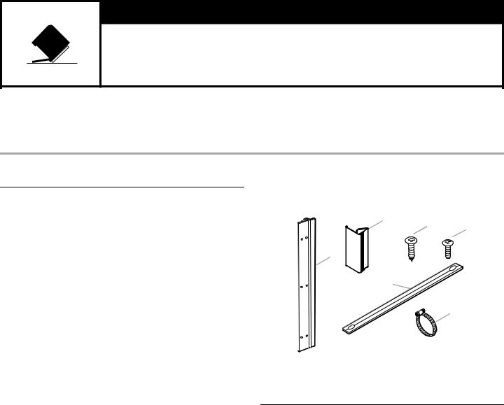
Parts Supplied
Check that all parts are included.
A |
|
B |
C |
|
|
E |
|
D |
|
|
F |
A. Sound seals (on some models) (2) |
D. Toekick panel seal |
B. Countertop mounting screws (2) |
(on some models) |
C. Mounting screws (8) |
E. Mounting strips (2) |
|
F. Large drain hose clamp |
Location Requirements
IMPORTANT: Observe all governing codes and ordinances. Failure to meet codes and ordinances could lead to fire or electrical shock.
Proper installation is your responsibility.
■Grounded electrical supply required
■Contact a qualified installer to ensure that the dishwasher is installed to meet all electrical and plumbing national and local codes and ordinances.
■Install the dishwasher as specified in these instructions.
■Have everything you need to properly install dishwasher.
■Keep water lines leading to the dishwasher from freezing to avoid damage to the dishwasher. Damage from freezing is not covered by the warranty.
■This dishwasher is manufactured for indoor use only.
■Do not run drain lines, water lines or electrical wiring where they can interfere with or contact the dishwasher motor or legs.
■The location where the dishwasher will be installed must provide clearance between motor and flooring. Motor should not touch the floor.
■Do not install dishwasher over carpeted flooring.
3
Minimum Clearances
Check location where the dishwasher will be installed. The location must provide:
■Easy access to water, electricity and drain.
■Convenient access for loading and unloading dishes. Corner locations require 2" (5.1 cm) minimum clearance between the side of the dishwasher door and the wall or cabinet.
■A minimum of 25⁄" (65.1 cm) is required in front of the dishwasher to allow the door to open fully.
C
B
A D
A. 2" (5.1 cm) minimum clearance |
C. Countertop |
for door opening |
D. 25⁄" (65.1 cm) minimum |
B.Dishwasher
■Square opening for proper orientation.
■Cabinet front perpendicular to floor.
■If the dishwasher will be left unused for a period of time or in a location where it may be subject to freezing, have it winterized by authorized service personnel.
Electrical Requirements
 WARNING
Electrical Shock Hazard
Plug into a grounded 3 prong outlet.
Do not remove ground prong.
Do not use an adapter.
Do not use an extension cord.
Failure to follow these instructions can result in death, fire, or electrical shock.
GROUNDING INSTRUCTIONS
■For a grounded, cord-connected dishwasher:
The dishwasher must be grounded. In the event of a malfunction or breakdown, grounding will reduce the risk of electric shock by providing a path of least resistance for electric current. The dishwasher is equipped with a cord having an equipment-grounding conductor and a grounding plug. The plug must be plugged into an appropriate outlet that is installed and grounded in accordance with all local codes and ordinances.
WARNING: Improper connection of the equipment-grounding conductor can result in a risk of electric shock. Check with a qualified electrician or service representative if you are in doubt whether the dishwasher is properly grounded. Do not modify the plug provided with the dishwasher; if it will not fit the outlet, have a proper outlet installed by a qualified electrician.
■For a permanently connected dishwasher:
The dishwasher must be connected to a grounded metal, permanent wiring system, or an equipmentgrounding conductor must be run with the circuit conductors and connected to the equipmentgrounding terminal or lead on the dishwasher.
SAVE THESE INSTRUCTIONS
It is the customer's responsibility:
■To contact a qualified electrical installer.
■To assure that the electrical installation is adequate and in conformance with National Electrical Code, ANSI/NFPA 70 - latest edition, and all local codes and ordinances.
4
Requirements:
■120-volt, 60 Hz, AC-only, 15or 20-amp fused electrical supply
■Copper wire only, 2 wire with ground
Recommended:
■Time-delay fuse or circuit breaker
■Separate circuit
Direct Wire Connection
■Use flexible, armored or nonmetalic sheathed, copper wire with grounding wire that meets the wiring requirements for your home and local codes and ordinances.
■Use a UL-listed/CSA-approved conduit connector.
Power Supply Cord Connection
Use Power Supply Cord Kit (Part Number 4317824) marked for use with dishwashers. Kit contents include:
■Voltex, Inc., UL-listed 16-gauge 3-wire power supply cord with a 3 prong grounding plug
■Neer C-500 ⁄" strain relief
■3 wire connectors
■Grommet (Part Number 302797)
Follow the kit instructions for installing the power supply cord.
NOTE: Power supply cord must plug into a mating, grounded 3 prong outlet, located in the cabinet next to the dishwasher opening. Outlet must meet all local codes and ordinances.
IMPORTANT: If you plan to install a garbage disposal, an additional separate 120-volt, 60 Hz, AC-only, 15or 20-amp fused electrical supply is required.
Water Supply Requirements
■A hot water line with 20-120 psi (138-862 kPa) water pressure.
■120°F (49°C) water temperature at dishwasher.
■³⁄" O.D. copper tubing with compression fitting or flexible braided water supply line.
NOTE: ½" minimum plastic tubing is not recommended.
■90º elbow with ³⁄" N.P.T. external pipe threads on one end.
IMPORTANT: Do not solder within 6" (15.2 cm) from water inlet valve.
Drain Requirements
■Use the new drain hose supplied with your dishwasher. NOTE: If a longer drain hose is required:
■Use a new drain hose with maximum length of 12 ft (3.7 m) that meets all current AHAM/IAPMO test standards.
■Use a new drain hose that is resistant to heat and detergent.
■Use a new drain hose that fits the 1" (2.5 cm) drain connector on the dishwasher.
■Connect drain hose to waste tee or disposal inlet above drain trap in house plumbing.
■Connect drain hose to house plumbing 20" (50.8 cm) minimum above the floor.
NOTE: It is recommended that the drain hose either be looped up and securely fastened to the underside of the counter, or be connected to an air gap.
■Use a drain air gap if the drain hose is connected to house plumbing lower than 20" (50.8 cm) above the subfloor or floor.
Drain Air Gap
■Use ½" (1.3 cm) minimum I.D. drain line fittings.
■If required, the drain air gap should be installed in accordance with the drain air gap installation instructions. When connecting the drain air gap, a rubber hose (not provided) will be needed to connect to the waste tee or disposer inlet.
NOTE: Do not connect drain lines from other devices to the dishwasher drain hose.
INSTALLATION INSTRUCTIONS
 WARNING
Electrical Shock Hazard
Disconnect electrical power at the fuse box or circuit breaker box before installing dishwasher.
Failure to do so can result in death or electrical shock.
1.Disconnect power.
2.Turn off water supply.
Prepare Cabinet Opening—
Existing Utility Hookups
Follow the steps in this section if you are installing the dishwasher in an existing cabinet opening with utility hookups.
1.Check that the water supply line reaches to the front left-hand side of the opening where the water connection will be made.
2.Check that the direct wire reaches to the front right-hand side of the opening where the electrical connection will be made.
A
6" (15.2 cm)
B
A. Water supply line
B. Direct wire
3. If the existing utilities extend to the locations shown, see “Install Drain Hose.”
4. If the utilities do not extend to the locations shown, see “Prepare Cabinet Opening—No Existing Utility Hookups.”
5
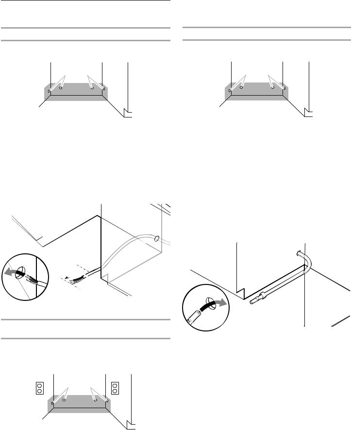
Prepare Cabinet Opening—No Existing
Utility Hookups
Install Electrical Connection—Direct Wire Method
1.Drill a ³⁄ " (1.9 cm) hole in the right-hand cabinet side or the rear of the opening.
A B
A.Optional locations
B.Preferred locations
2.If the cabinet is wood, sand the hole until smooth. If the cabinet is metal, cover the hole with a grommet (not provided).
3.Route the wire from the power supply through the cabinet hole. The wire must extend to the front right-hand side of the cabinet opening.
4.Tape the wire to the floor in the area shown. This will keep the wire from moving when the dishwasher is moved into the cabinet opening.
A 
A. 6" (15.2 cm)
Install Electrical Connection—Power Supply Cord
Method
NOTE: A mating, grounded 3 prong outlet is required in a cabinet next to the dishwasher opening.
1.Drill a 1¹⁄ " (3.8 cm) hole in the cabinet side or the rear of the opening.
A B
A.Optional locations
B.Preferred locations
2.If the cabinet is wood, sand hole until smooth. If the cabinet is metal, cover the hole with a grommet (Part Number 302797) included with power supply cord kit. See “Electrical Requirements.”
Install Water Line
1.Drill a ¹⁄ " (1.3 cm) hole in the left-hand cabinet side or the rear of opening.
A B
A.Preferred locations
B.Optional locations
2.Measure the overall length of the water line (copper tubing or flexible braided water supply line) required.
3.Attach the water line (copper tubing or flexible braided water supply line) to the hot water supply line in compliance with local codes and ordinances.
NOTE: The hot water supply line should have a manual shutoff valve.
4.Slowly route the water line (copper tubing or flexible braided water supply line) through the hole in the cabinet.
NOTE: Copper tubing will bend and kink easily.
The water line (copper tubing or flexible braided water supply line) should be far enough into the cabinet opening to connect to the dishwasher inlet on the front left-hand side of the dishwasher.
6
5.Turn on the water shutoff valve. Run water into a shallow pan to flush the water line (copper tubing or flexible braided water supply line) of particles that may clog the inlet valve.
6. Turn off the water shutoff valve.
Install Drain Hose
IMPORTANT: Always use a new drain hose even when installing a new replacement dishwasher.
■Drill a 1¹⁄ " (3.8 cm) diameter hole in the cabinet wall on the side of the opening closest to the sink.
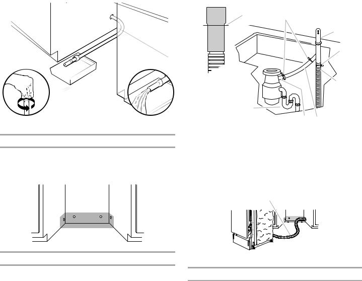
Connect Drain Hose to Air Gap—Waste Disposer
1.Remove the waste disposer knockout plug. Cut the end of the drain hose, if needed.
NOTE: Do not cut the ribbed section.
2.Attach the drain hose to the air gap with the large drain hose clamp (provided).
NOTE: If the drain hose was cut, use 1¹⁄ " to 2" (3.8 to 5 cm) screw-type clamp (not provided).
3.Use a rubber hose connector (not provided) with screw-type clamps (not provided) to connect the air gap to the waste disposer inlet above the drain trap and at least 20" (50.8 cm) above the floor.
A
B
C
D
|
|
E |
H |
|
|
|
G |
F |
A. Drain hose—cut here, if needed |
E. Drain hose |
|
B. Screw-type clamps |
F. Rubber hose connector |
|
C. Air gap |
(not provided) |
|
D. Large drain hose clamp |
G. Disposer inlet |
|
(provided) |
H. Drain trap |
|
4.Insert the drain hose through the hole cut in the cabinet and to the front and center of the opening where the drain connection will be made.
A
A. Drain hose
Connect Drain Hose to Air Gap—No Waste Disposer
1.Cut the end of the drain hose, if needed. NOTE: Do not cut the ribbed section.
2.Attach the drain hose to the air gap with the large drain hose clamp (provided).
NOTE: If the drain hose was cut, use 1¹⁄ " to 2" (3.8 to 5 cm) screw-type clamp (not provided).
7
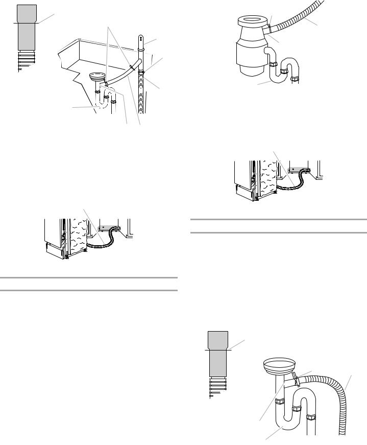
3.Use a rubber hose connector (not provided) with screw-type clamps (not provided) to connect the air gap to the waste tee above the drain trap and at least 20" (50.8 cm) above the floor.
A
H
A.Drain hose—cut here, if needed
B.Screw-type clamps (not provided)
C.Air gap
D.Large drain hose clamp (provided)
B
C
D

 E
E
GF
E.Drain hose
F.Rubber hose connector (not provided)
G.Waste tee
H.Drain trap
4.Insert the drain hose through the hole cut in the cabinet and to the front and center of the opening where the drain connection will be made.
A
A. Drain hose
Connect Drain Hose to Waste Disposer—No Air Gap
1.Remove the waste disposer knockout plug. NOTE: Do not cut the end of the drain hose.
2.Attach the drain hose to the waste disposer inlet with the large drain hose clamp (provided).
This connection must be before the drain trap and at least 20" (50.8 cm) above the floor.
NOTE: It is recommended that the drain hose be looped up and securely fastened to the underside of the counter.
C
D
A. Large drain hose clamp (provided) |
C. Disposer inlet |
B. Drain hose |
D. Drain trap |
3.Insert the drain hose through the hole cut in the cabinet and to the front and center of the opening where the drain connection will be made.
A
A. Drain hose
Connect Drain Hose—No Waste Disposer or Air Gap
1.Cut the end of the drain hose, if needed. NOTE: Do not cut the ribbed section.
2.Attach the drain hose to the waste tee with the large drain hose clamp (provided).
NOTES:
■If the drain hose was cut, use 1¹⁄" to 2" (3.8 to 5 cm) screw-type clamp (not provided).
■This connection must be before the drain trap and at least 20" (50.8 cm) above the floor.
■It is recommended that the drain hose be looped up and securely fastened to the underside of the counter.
A
B C
E
D
A. Drain hose—cut here, if needed |
D. Drain trap |
B. Large drain hose clamp (provided) |
E. Waste tee |
C. Drain hose |
|
8

Prepare Dishwasher
 WARNING
Tip Over Hazard
Do not use dishwasher until completely installed. Do not push down on open door.
Doing so can result in serious injury or cuts.
 WARNING
Excessive Weight Hazard
Use two or more people to move and install dishwasher.
Failure to do so can result in back or other injury.
1.Fold insulation down over back and sides of dishwasher (on some models).
3.Using a ¹⁄" hex socket, nut driver or Phillips screwdriver, remove the 4 screws attaching the toekick panel and lower panel to the dishwasher.
NOTE: Do not remove the tech sheet from the access panel.
4.Remove both panels and set aside on a covered surface.
5.Apply plumber’s tape or pipe joint compound to the 90º elbow fitting and connect the fitting to the water inlet valve.
2.Using 2 or more people, place the dishwasher on its back on a piece of cardboard.
NOTE: If the door panel will be used as a work table, place a towel over it to avoid damage to the door panel.
6.Tighten the 90º elbow fitting until snug.
NOTE: Elbow should face to the rear of the dishwasher.
A


B
A.Water inlet valve
B.Elbow
9
Prepare Terminal Box
1.Using a ¹⁄" hex-head socket, nut driver or Phillips screwdriver, remove the terminal box cover. Lay the cover aside.
2.Install a UL-listed/CSA-approved conduit connector (may be provided in power supply cord kit [Part Number 4317824]). Check that screwheads are facing to the left when tightening the conduit nut.
NOTE: If your dishwasher will be connected by the direct wire connection, please see “Adjust Leveler Legs.”
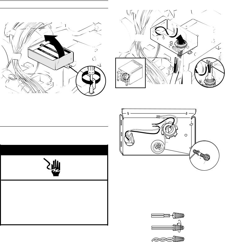
Make Electrical Connections—Power
Supply Cord Method
 WARNING
Electrical Shock Hazard
Electrically ground dishwasher.
Connect ground wire to green ground connector in terminal box.
Do not use an extension cord.
Failure to follow these instructions can result in death, fire, or electrical shock.
The power supply cord and connections must comply with the National Electrical Code, Section 422 and/or local codes and ordinances. Install the power supply cord according to the installation instructions included with the power supply cord kit.
1.Route the power supply cord so that it does not touch the dishwasher motor or the lower part of the dishwasher tub.
2.Pull the power supply cord through the conduit connector in the terminal box.
3.Remove the green grounding screw and place the screw through the ring terminal of the green ground wire. Reattach and tighten the green grounding screw.
A
 A
A

 B
B
C
A.Green ground wire
B.Washer
C.Green grounding screw
4.Using UL-listed/CSA approved twist-on connectors sized to connect the power supply cord to 16-gauge dishwasher wire, connect the white wire from the power supply cord to the white wire on the terminal box.
10
5.Using UL-listed/CSA approved twist-on connectors sized to connect power supply cord to 16-gauge dishwasher wire, connect the black wire from the power supply cord to the black wire on the terminal box.
6.Tighten the conduit connector screws to secure the power supply cord.
Adjust Leveler Legs
1. Measure the cabinet opening height.
7.Insert tabs on the left-hand side of the terminal box cover.
8.Using a ¹⁄ " nut driver and previously removed screw, reinstall the terminal box cover with the wires inside terminal box.
9. Check that no wires are pinched by the cover.
NOTE: Do not plug power supply cord into outlet until instructed.
23⁄" - 24 |
³⁄" |
|
|
|
|
|
|||||
(60.6 |
cm - |
|
|
|
|
|
|||||
|
|
62 |
cm) |
|
|
||||||
|
|
|
|
|
|
||||||
|
|
|
|
|
|
|
|
|
|||
24" |
cm) |
33 |
¹⁄ |
"*- |
|
|
|
||||
(61 |
(85. |
1 |
|
35" |
|
||||||
|
|
|
|
|
|||||||
|
|
|
|
|
|
|
|
cm |
- |
|
|
|
|
|
|
|
|
|
|
|
|
88.9 |
cm) |
|
|
|
|
|
|
|
|
|
|
|
|
2.Adjust the dishwasher leg height according to the following chart. Turn both of the leveler legs to the same height.
Height |
Adjusted Leg Height |
Adjusted Leg |
|
(H) |
Height (X) |
(H) |
Height (X) |
33¹⁄ " (85.1 cm) |
0" |
34³⁄ " (87.4 cm) |
⁄ " (2.2 cm) |
|
|
|
|
33 ⁄ " (85.4 cm) |
¹⁄ " (0.3 cm) |
34¹⁄ " (87.7 cm) |
1" (2.5 cm) |
|
|
|
|
33³⁄ " (85.7 cm) |
¹⁄ " (0.6 cm) |
34 ⁄ " (88 cm) |
1¹⁄ " (2.8 cm) |
|
|
|
|
33 ⁄ " (86 cm) |
³⁄ " (1 cm) |
34³⁄ " (88.3 cm) |
1¹⁄ " (3.1 cm) |
|
|
|
|
34" (86.4 cm) |
¹⁄ " (1.3 cm) |
34 ⁄ " (88.6 cm) |
1³⁄ " (3.5 cm) |
|
|
|
|
34¹⁄ " (86.7 cm) |
⁄ " (1.6 cm) |
35" (88.9 cm) |
1¹⁄ " (3.8 cm) |
|
|
|
|
34¹⁄ " (87 cm) |
³⁄ " (1.9 cm) |
|
|
|
|
|
|
X |
1" |
2" |
11
 Loading...