


RSS307
Amana RSS307, RSS352-OF, RSS353-OF, RSS354-OF, RSS355-OF Service Manual
...
Service
RST and RSS
Gas Ranges
Models and manufacturing numbers
in this manual see page 2A.
Service Manual for
Caloric
®
This manual is to be used by qualified appliance
technicians only. Amana does not assume any
responsibility for property damage or personal injury
for improper service procedures done by an
unqualified person.
RC231002
Revision 3
May 1998

INDEX
General Information. ............................................................................................. 3 - 6
Installation Instructions.......................................................................................... 7 - 20
Safe Operating Procedures ................................................................................... 21 - 23
Operation And Service Procedure
Electronic Clock Timer (Slide in Models) ......................................................... 24 - 31
Electronic Range Control (Two Piece Control) ................................................ 32 - 45
Electronic Range Control (One Piece Control) ................................................ 46 - 55
Automatic Electronic Timer .............................................................................. 56 - 59
Cook And Off Clock Timer ............................................................................... 60 - 64
Clock Timer - Mechanical ................................................................................ 65 - 66
Automatic Electronic Timer (Solid State) ......................................................... 67 - 69
Bake And Broil Ignitors, Electric Gas Valve ..................................................... 70
Selector Switch, Oven Thermostat .................................................................. 71
Spark Module, Spark Switch ............................................................................ 72
Door Latch Mechanism, Latch Switch ............................................................. 73
Troubleshooting Guide .......................................................................................... 74 - 84
Disassembly Procedures....................................................................................... 85 - 99
Upper Oven Operation And Service Procedures .................................................. 100 - 106
Wiring Diagrams and Schematics ......................................................................... 107 - 123
REPLACE MANUAL 56397 AND 56074 WITH THIS MANUAL, RC231002.
REV. 1 - ADDED RSS MODELS TO MANUAL.
REV. 2 - ADDED RST382UK, P1141228N; RST388UWW, P1141246N; and RST399UL/W, P1132642N.
RC231002 Rev. 3 2

MODEL AND MANUFACTURING NUMBERS
MODEL M/N
RSS307
RSS307-OF
RSS343
RSS352-OF
RSS353-OF
RSS354-OF
RSS355-OF
RSS356UL P1141233N, P1141234N, P1130975N
RSS356UW P1141233N, P1141234N, P1130975N
RSS358UL P1130875N, P1141226N, P1130974N
RSS358UL P1141231N
RSS358ULG P1141218N, P1141226NLG, P1141232N
RSS358ULGCO P1141219N
RSS358UW P1130875N
RSS358UW/L P1141231N
RSS358UWG P1141218N, P1141226NWG, P1141232N
RSS358UWGCO P1141219N
RSS359
RSS359-OF
RSS361
RSS361-OF
RSS363
RSS363-OF
RSS369
RSS369-OF
RSS380
RSS380-OF
RST307
RST308UK P1130723N, P1130725N, P1130727N
RST308UW P1130723N, P1130725N, P1130727N
RST308UL P1130723N, P1130725N, P1130727N
RST308UWW P1130724N, P1130725N
RST308UWW1 P1130726N, P1130728N
RST309
RST354
RST359
RST361
RST362
RST365
RST369
RST376
RST378UL P1141203N
RST378UW P1141203N
RST380
RST381
RST382UK P1141220N, P1141228N
RST387
RST388UWW P1141221N, P1141229N, P1141246N
RST3997UL/W P1132635N, P1132642N, P1132621N, P1132622N
2A RC231002 Rev. 3
IMPORTANT INFORMATION
Great pride and workmanship go into every product to provide our Customers with the highest possible quality. We
realize, however, that during its lifetime the product may require service. The information contained in this manual is
intended for use by a qualified service technician who is familiar with the safety procedures required in the repair and
who is equipped with the proper tools and testing instruments.
REPAIRS COVERED IN THIS MANUAL THAT ARE MADE BY UNQUALIFIED PERSONS CAN RESULT IN
HAZARDS DUE TO IMPROPER ASSEMBLY OR ADJUSTMENTS SUBJECTING INEXPERIENCED PERSONS
MAKING SUCH REPAIRS TO THE RISK OF INJURY OR ELECTRICAL SHOCK WHICH CAN BE SERIOUS OR
EVEN FATAL.
IMPORTANT NOTE TO CONSUMER
IF YOU PERFORM SERVICE ON YOUR OWN PRODUCT, YOU MUST ASSUME RESPONSIBILITY FOR ANY
PERSONAL INJURY OR PROPERTY DAMAGE WHICH MAY RESULT. AMANA WILL NOT BE RESPONSIBLE
FOR ANY INJURY OR PROPERTY DAMAGE ARISING FROM IMPROPER SERVICE AND/OR SERVICE
PROCEDURES.
In order to locate an authorized service agency. please consult your telephone book or the dealer from whom you
purchased this product. If you require further assistance, please contact:
CUSTOMER RELATIONS DEPT. OR 1-319-622-5511
AMANA, IOWA 52204 CALL and ask for the
Customer Relations Department
Users of Caloric products outside of the United States and Canada should contact:
EXPORT CUSTOMER RELATIONS DEPARTMENT
AMANA REFRIGERATION, INC.
AMANA, IOWA 52204, USA
TELEX: 4330076 AMANA
CABLE: "AMANA", AMANA, IOWA, USA
RECOGNIZE SAFETY SYMBOLS, WORDS AND LABELS
DANGER - Immediate hazards which WILL result in
severe personal injury or death.
WARNING - Hazards or unsafe practices which COULD
result in severe personal injury or death.
CAUTION - Hazards or unsafe practices which COULD
result in minor personal injury or product or property
damage.
RC231002 Rev. 3 3
GENERAL INFORMATION
F
r
e
e
o
V
V
V
GENERAL INFORMATION
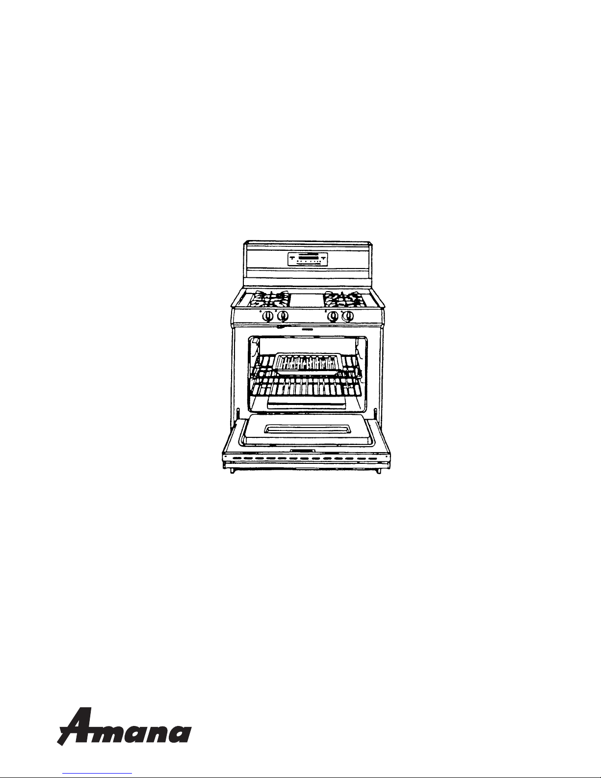
This manual provides you with complete instructions and
suggestions for handling, installing, and servicing Caloric
Self-Cleaning Gas Ranges.
This manual is based on information gained through
experience and careful testing. This information, if followed carefully, will assure the customer of proper unit
operation with a minimum of servicing requirements, thus
insuring the maximum benefits of clean, modern cooking.
Unless the unit is properly installed and carefully explained, the customer will not receive the utmost advantages that gas cooking provides.
Feel free at all times, to call Caloric to discuss any
problems which may not be fully understood.
Refer to the Parts Catalog when replacement parts are
needed.
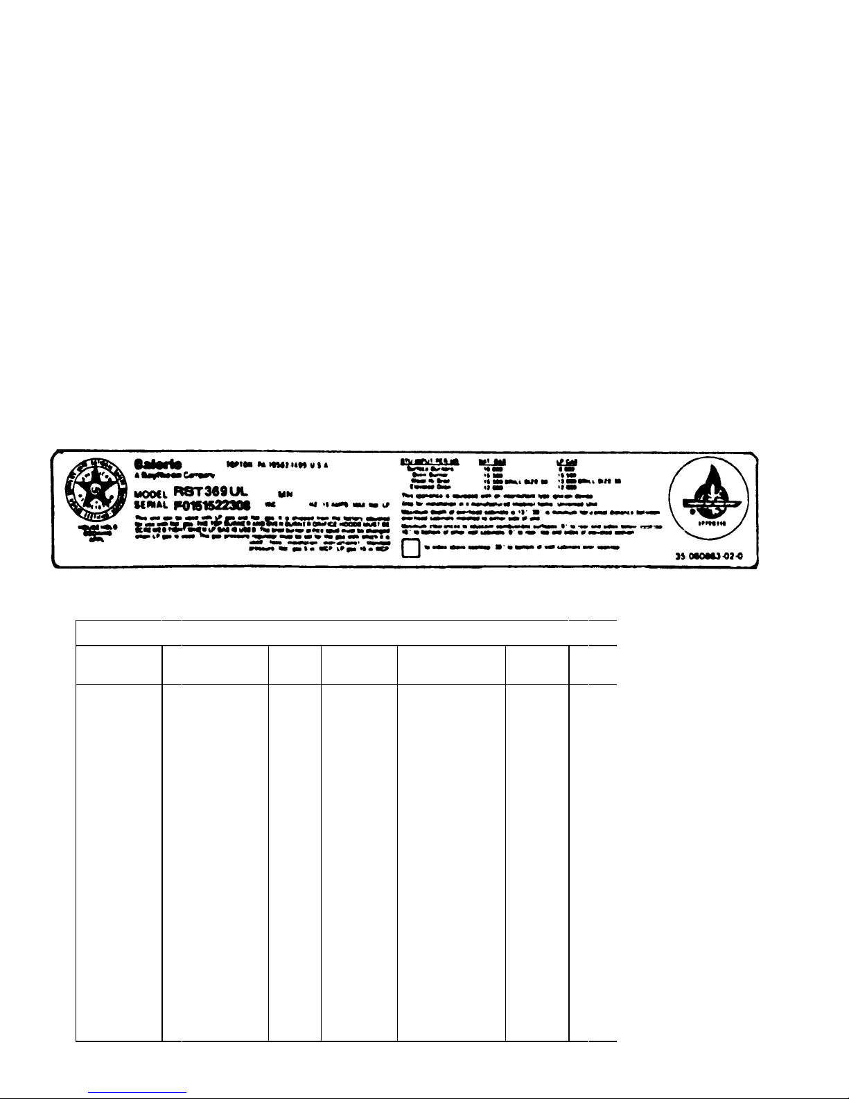
MODEL IDENTIFICATION
The correct model number, manufacturing number (MN or
P), and serial number should be known prior to ordering
parts so that incorrect shipments and delays can be
avoided. (See Rating Label example.)
The rating label is located in the burner box of the unit and
can be observed by raising the main top. The rating label
on sealed burner units is located on the front frame behind
the storage drawer.
The wiring diagram is located on the bottom of the storage
drawer assembly.
E
Electric
R
Gas
T
Trash
Compactor
H
Vent Hood
Microwave
M
CALORIC MODEL DESCRIPTION BREAKDOWN
R S T 3 8 O
PRODUCT
LINE
PRODUCT TYPE SERIES
C
Convertible
H
High Boil
J
Hi-Broil w/ Cont.
Cleaning Panels
Upper Oven
Microwave
K
Lower-Self
Cleaning
Low boil
Low Boil w/
L
Cont. Cleaning
M
Panels
Portable
Self-Clean
P
Cook Top
S
Under-Counter
T
Wall Oven
U
Wall Oven w/
W
Cont. Cleaning
X
Panels
Self-Cleaning
Wall Oven
Y
MicroCombination
R
D
S
T01
2
3
4
6
WIDTH
ON TOP
No Width
Required
15" - 18"
20" - 18"
30" - 35"
40" - 42"
36"
BACKGUARD FEATURE
0
No Backguard
1
Plain Rail/
Laminated Top
Plain Rail/
2
Cutting Board
4" Backguard
3
w/Auto-Timer
Special
4
Designation
Standard
5
Deluxe
6
Backguard
Special
7
Designation
Deluxe
8
Backguard
Double Decker
9
Varible N
Natu
L
Bottl
U
Univ
X
Exp
1
115
2
230
8
208
RC231002 Rev. 3 4

GENERAL INFORMATION
RECEIVING
Inspect unit thoroughly at time of delivery. Report any
visible damage to the carrier immediately. If the damage
is "concealed" and not discovered until after delivery has
been accepted, make a "concealed damage report" to the
carrier. "Concealed damage report" forms may be obtained from the carrier's agent.
This procedure must be followed: All shipments, i.e.,
complete range or parts, are shipped at the buyer's risk.
Manufacturer's responsibility ends when the consignment
is accepted by the carrier in "good order". Manufacturer
will give every assistance on damage claims by supplying
any necessary supporting papers, such as invoices or bills
of lading. It must be understood that this assistance does
not imply acceptance of responsibility for settlement of
such claims. Claims for loss or damage cannot be deducted from the invoice or payment of the invoice cannot
be withheld pending adjustment of claims. Do not return
any unit or parts for credit without written consent.
CARE AND HANDLING OF PORCELAIN ENAMEL
1. Porcelain enamel is glass that has been fused onto a
metal surface. Because it is glass, however, it cannot
be guaranteed.
It is impossible to make perfect color match in commercial enamel, and occasional variations must be
expected. Minor imperfections are not just causes for
complaint or rejection.
Porcelain will not stand heavy, sharp blows from
cooking utensils or any other object.
soon as cool enough using dry cloth. If not cleaned,
there may be noticeable smoke, odor, or visible dirt
the next time the unit is used.
3. Crazing - Craze is the name given to the small hair
line marks which are sometimes found in enameled
surfaces after use. They look like little cracks, but
they are not. The enamel around them will never chip
or peel off due to these marks. As we cannot
guarantee enamel against crazing or discoloration,
the customer should be informed as to the proper care
of enamel.
To the customer, any mark is a defect, as they do not
understand enamel. They are afraid the enamel will
peel or crack off leaving a rusty spot. This is not true
as craze marks will never peel or crack. A craze mark
is simply a place where the outer coat of enamel has
separated. The dark color that appears in the crack
is dust that catches in the opening.
To service a craze complaint, it is best to use the
following: Explain crazing to the customer using as
an illustration the effect of hot water in a cold glass it cracks. Compare it to the hairlines in dishes and
cups due to continued heating and cooling. If the
customer can be made to understand that the enamel
will never come off, the customer will be satisfied.
One point to remember with service calls on crazing
is to take care of it immediately. The longer the
customer has to wait, the worse it appears to her.
While this is true of all service work, it is especially
true of crazing complaints. Make it a point to go out
the same day the complaint is received.
In cleaning enamel, soap and water will usually
suffice. Remove any discoloration promptly, but do
not apply cold water to a hot surface.
Fruit juices, vegetable acids, sour milk, or strong
mineral acids may discolor or etch enamel.
2. Cleaning Broiler Pan
For simplest method of cleaning, it is recommended
that broiler pan be submerged in warm water immediately after use. Use a stiff brush, if necessary.
Reheating broiler pan after it has been used without
cleaning will result in fats and greases burning on and
becoming much more difficult to remove.
NOTE: After the food has been removed from the
oven or broiler, and the unit has been turned off, leave
the oven and broiler door open for a few minutes to dry
out the interior. If food has cooked over or grease has
spattered the interior, clean the parts thoroughly as
CARE AND HANDLING OF CHROME, GLASS, OR
METAL FINISH
To keep the stainless, chrome, or glass finishes "looking
new" wash with soap and water, rinse, then dry with a clean
cloth. If a polish is necessary, only the highest quality
chrome cleaning compounds are recommended.
Finger marks and smears may easily be removed with a
mild cleaner such as glass wax and simonize cleaner.
Such agents should be used sparingly. Never use ordinary
steel wool as it may leave a film of iron which will rust and
discolor creating the illusion that the finish is rusting.
Never use harsh, gritty cleaners which can "age" or damage the porcelain and/or polished metal trim.
Never use strong chemical oven cleaners in a self-clean
oven. They are unnecessary and their residues can
produce noxious odors during self-clean, with oven temperatures of 900°F. or more.
5 RC231002 Rev. 3

GENERAL INFORMATION
SPECIFICATIONS - Burner Ratings - RST
Non Sealed Nat 10,000 BTU/HR
Top Burner LP 7,000 BTU/HR
Sealed Top Nat 9,000 BTU/HR
Burner LP 7,000 BTU/HR
Cast Sealed RST/RSS
Top Burner
Large (3) Nat 9,000 BTU/HR
LP 8,000 BTU/HR
Small (1) Nat 7,000 BTU/HR
LP 6,000 BTU/HR
Oven Burner Nat 15,500 BTU/HR
Lower LP 15,000 BTU/HR
Broil Nat 15,500 BTU/HR
Burner LP 13,000 BTU/HR
Oven Burner Nat 12,000 BTU/HR
Upper LP 12,000 BTU/HR
BURNER ORIFICE SIZES - Universal Models
SPECIFICATIONS - Burner Ratings - RSS
NON SEALED
Top Burner Nat 10,000 BTU/HR
Top Burner LP 8,000 BTU/HR
Oven Burner Nat 15,5000 BTU/HR
Lower LP 15,500 BTU/HR
Broil Nat 15,500 BTU/HR
Burner LP 13,000 BTU/HR
Non Sealed Top Burners are equipped with #54 double
coaxial orifices and universal pin.
Sealed Top Burners are equipped with a 4-#54 orifice
spud for natural gas and separately packed 4-#68 orifice
spud to convert to LP gas.
or
beginning October 22, 1990 at serial number F0430127550
the venturi type top burners are equipped with #54 double
coaxial orifices and universal pin.
Cast Sealed Top Burners are equipped with 3-#54 double
coaxial orifices with universal pins and 1-#56 double
coaxial orifice with universal pin.
Lower Oven Burner is equipped with a #50 double coaxial
orifice and universal pin.
Broil Burner is equipped with a #54 orifice spud and
separately packed orifice spud to convert to LP gas.
Upper Oven Burner is equipped with a #52 double coaxial
orifice and universal pin.
ELECTRICAL REQUIREMENTS
These ranges should be connected to a separate 115 volt,
60 cycle AC three-wire "U" ground receptacle, parallel
slots.
RC231002 Rev. 3 6
INSTALLATION INSTRUCTIONS
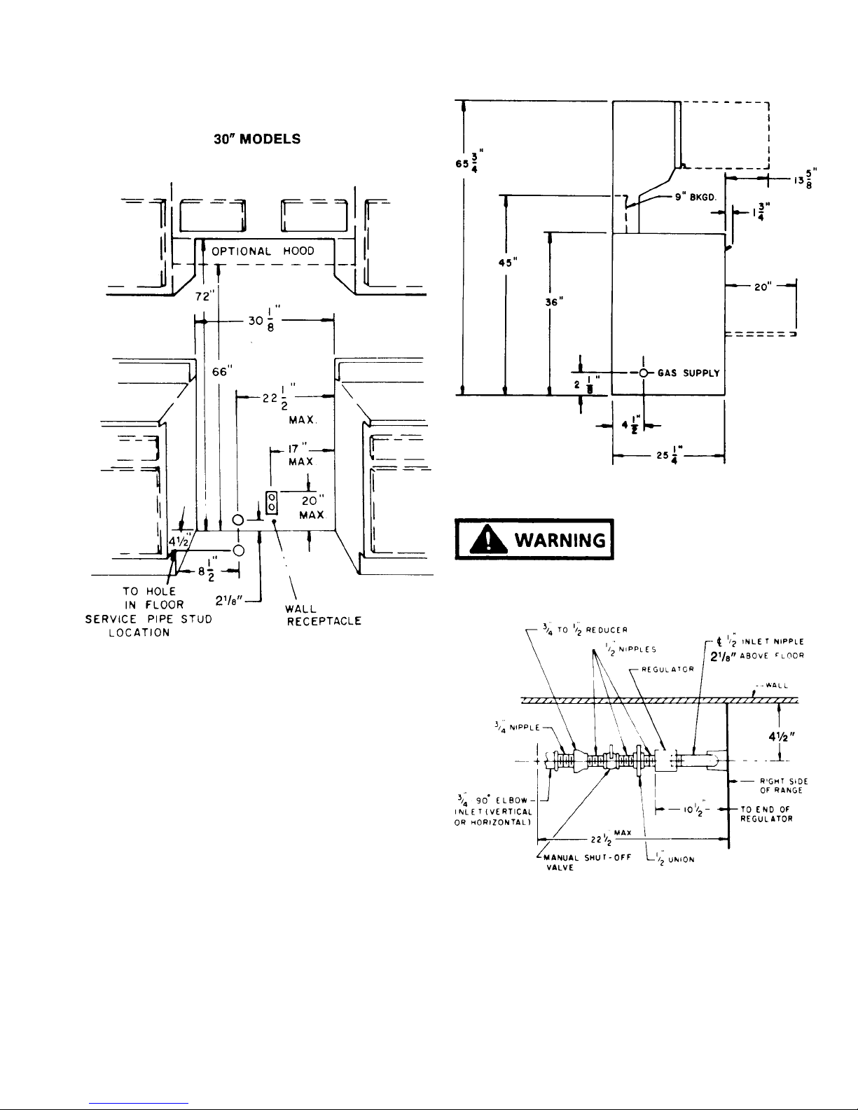
SUGGESTED LOCATION OF SERVICE PIPE - REAR
WALL OR FLOOR
FIGURE 1
UNIVERSAL MODELS (Nat or LP Gas)
The regulator is factory adjusted for natural gas with a
supply line pressure of not less than 6-inches water column
pressure (W.C.P.). With the regulator adjusted for liquefied petroleum (LP) gas, the minimum supply pressure is
11 inches W.C.P. For conversion procedure to LP gas see
the section on regulators and LP conversion procedures.
Cabinet Installation opening for gas slide-in range. See
Page 10.
FIGURE 2
FIRE OR EXPLOSION
HAZARD
THE MAXIMUM GAS SUPPLY PRESSURE FOR THESE
MODELS MUST NOT EXCEED 14-INCHES W.C.P.
Top View
Figure 3
7 RC231002 Rev. 3
INSTALLATION INSTRUCTIONS
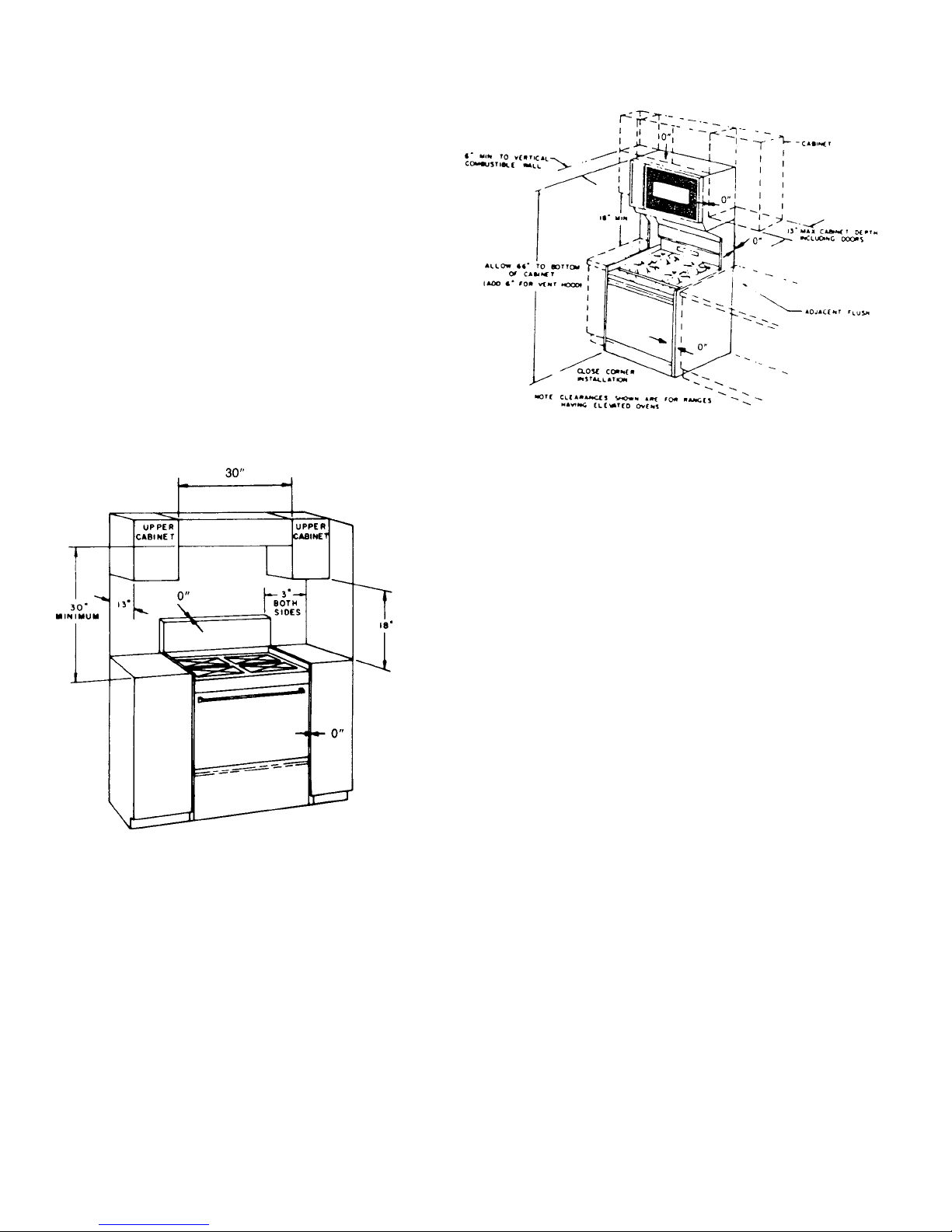
INSTALLATION
Location
The location of the range should be selected so proper
illumination, freedom from drafts, and convenience to
other appliances in the kitchen are obtained. Carefully
level the range, using the leveling legs provided. The
range must be level in order to assure uniform cooking and
baking. A level or a large pan of water placed on an oven
rack or on top of range can be used to level the unit. The
range is to be installed flush to rear wall, and may be
installed flush to side base cabinets. Spacing to vertical
side wall above cooking surface 3" (as shown in Figure 2),
6" (as shown in Figure 3), for ranges with elevated ovens.
Minimum distance to horizontal combustible surface above
cooking surface is 30" and must be the width of the range.
Maximum depth of cabinets installed above the range is
13".
Ranges With Elevated Ovens
Figure 5
It is the responsibility of the installer to comply with the
installation clearances specified on the rating plate
attached to the appliance.
Single Ovens
Figure 4
NOTE: Clearance specified to combustible construction
(walls and materials) are based on a temperature rise of
wood structures resulting from appliance operation. These
clearances are suitable for walls of studding, lath and
plaster, or other types of combustible materials which have
a density of 20 pounds per cubic foot or more. No
evaluation of the clearances required has been made for
installations adjacent to low density cellulose, fiber board,
and similar materials which have a density of less than 20
pounds per cubic foot; nor to plastic tiles, or sheeting.
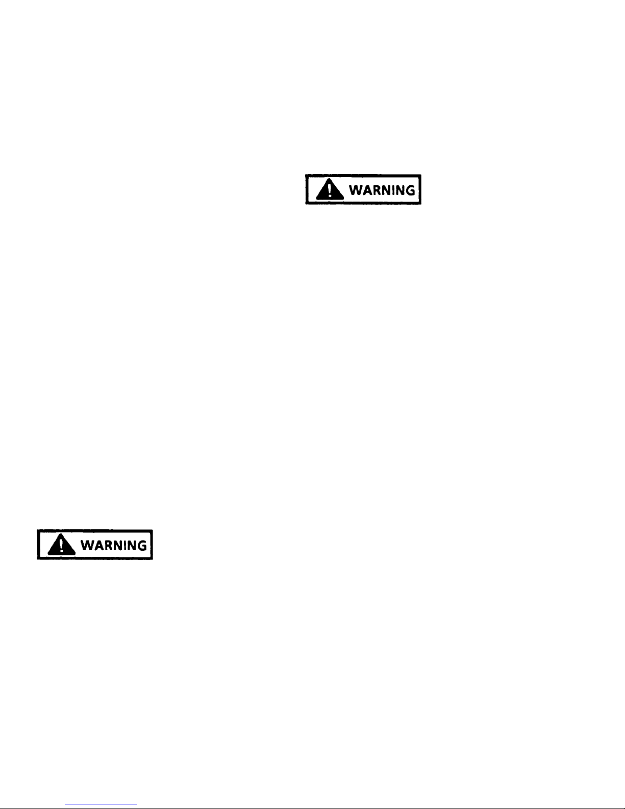
SECURE RANGE TO HOUSE STRUCTURE
For safety consideration means have been provided for
this range, except one having an elevated oven, to be
secured to th house wall behind the range, METHOD 1#
(see Figure 5A). If the wall behind the range is solid wood
or a vertical stud is available, a wood screw or lag bolt of
sufficient length may be employed to secure the range. If
the wall behind the range is not solid such as paneling or
dry wall (sheet rock) construction use of a Molly Bolt is
required. The anchor portion of the Molly Bolt should be of
sufficient lenght to hold it securely to the building material.
The thicker the material, the longer the anchor portion
must be.
RC231002 Rev. 3 8

INSTALLATION INSTRUCTIONS
Figure 5A
IN MOBILE HOMES:
Any installtion in a mobile home must conform with the
Manufactured Home Consutruction and Safety Standards.
Title 24CFR, Part 32-80 (in Canada, CSA standard Z240,4-
1) or when such standard is not applicable, with the local
codes.
For mobile home installation it is necessary to use alternate METHOD #2 (see Figure 5A) to secure range to floor.
See rating label to determine if range can be used in this
application.
ANY OPENINGS IN THE WALL BEHIND THE RANGE
OR THE FLOOR UNDER THE RANGE MUST BE SEALED.
Where local codes permit, a TEMPORARY CONNEC-
TION may be made to properly ground a two-prong wall
receptacle by the use of an adaptor which is available at
most local hardware stores.
An adaptor plug can temporarily be used (see Figure 4)
preferably with polarized male blades. If an unpolarized
adaptor plug must be used, determine which is the "hot"
side and ground. Place an identifying mark on the adaptor
to assure proper polarization in the future.
Figure 6
ATTACHING THE ADAPTOR GROUND WIRE TO THE
WALL RECEPTACLE COVER SCREW DOES NOT
GROUND THE APPLIANCE UNLESS THE COVER
SCREW IS GROUNDED THROUGH THE HOUSE
WIRING.
If there is any doubt as to whether the wall receptacle is
properly grounded, the customer should have it checked
by a qualified electrician.
DO NOT, UNDER ANY CIRCUMSTANCES, CUT OR
REMOVE THE THIRD (GROUND) PRONG FROM THE
POWER PLUG.
ELECTRICAL CONNECTIONS
FIRE OR EXPLOSION
HAZARD
FOR GROUNDING - THIS APPLIANCE MUST BE
ELECTRICALLY GROUNDED IN ACCORDANCE WITH
LOCAL CODES, OR, IN THE ABSENCE OF LOCAL
CODES, WITH THE NATIONAL ELECTRIC CODE, ANSI/
NFPA NO. 70-1990. FAILURE TO FOLLOW THESE
INSTRUCTIONS MAY RESULT IN ELECTRIC SHOCK,
PERSONAL INJURY OR DEATH.
The power cord on this appliance is equipped with a threeprong (grounding) plug which mates with standard threeprong (grounding) receptacles.
Where a standard two-prong wall receptacle is encountered, it is the personal responsibility and obligation
of the customer to have it replaced with a properly grounded
three-prong wall receptacle.
9 RC231002 Rev. 3
INSTALLATION INSTRUCTIONS
CONNECTING TO GAS SUPPLY LINE
Access to connection is behind bottom storage drawer.
The pressure regulator has a 1/2" female pipe thread. It is
recommended that a 1/2" close nipple, a union and shutoff valve, be assembled into the regulator. This places the
assembly for each connection to the gas supply and access
to the shut-off valve as illustrated in Figure 1.
The gas supply pipe to the range should be 3/4" rigid pipe
then reduced to 1/2" pipe at the pressure regulator. If a long
run of fuel is required, a larger size pipe may be required.
With the liquified petroleum (LP) gases, the size of the
piping or tubing can be 1/2" minimum. LP gas suppliers
usually determine the size and material used on the
system. We do not recommend that flexible connectors be
used in connecting our appliance to the gas supply, unless
American Gas Association approved. Poorly designed
connectors can be a source of gas leak. Even when AGA
approved flexible connectors are used the customer should
be cautioned against kinking or damaging the connector
when moving the range for cleaning or any reason. This
could cause a gas leak.
A shut-off valve should be installed in the line supplying
gas to the range. Check local building codes and utility
requirements. (See Figure 1 for details.)
A suitable pipe thread sealing material should be used,
which is approved for use with LP gases.
Caloric ranges are designed for easy connection between
the supply line and the inlet fitting. However, all strains
must be removed from the supply and fuel lines so the
range will be level and in line.
Use two (2) wrenches when connecting to the regulator.
burner valves should be closed and the gas supply turned
on. All connections in the gas supply line and in the range
should be tested with soap suds for any leaks. If a leak is
present, bubbles will appear. The leak should be corrected
by tightening the joint, or unscrewing it completely and
applying additional dope. Any connections which may
have been disturbed should be tested for leaks.
FIRE OR EXPLOSION
HAZARD
A LIGHTED MATCH OR FLAME SHOULD NEVER BE
USED WHEN TESTING FOR LEAKS. ALL FITTINGS
AND CONNECTIONS HAVE BEEN TIGHTENED AND
TESTED AT THE FACTORY. IF A LEAK IS DETECTED,
TIGHTEN THE FITTING, DO NOT USE PIPE DOPE ON
FACTORY FITTINGS.
The gas supply pipe to the range should be 3/4" rigid pipe
then reduced to 1/2" pipe at the pressure regulator. If a long
run of fuel line is required, a larger size pipe may be
required. With liquefied petroleum (LP) gases, the size of
the piping or tubing can be 1/2" minimum. LP gas suppliers
usually determine the size and material used on the
system. We do not recommend that flexible connectors be
used in connecting our appliance to the gas supply, unless
American Gas Association approved. Poorly designed
connectors can be a source of gas leak. Even when AGA
approved flexible connectors are used the customer should
be cautioned against kinking or damaging the connector
when moving the range for cleaning or any reason. This
could cause a gas leak.
A shut-off valve should be installed in the line supplying
gas to the range. Check local building codes and utility
requirements.
A suitable pipe thread sealing material should be used,
which is approved for use with LP gases.
FIRE OR EXPLOSION HAZARD - LEAK TEST
COMPONENTS AFTER CONNECTION.
THE REGULATOR IS DIE CAST AND WILL CRACK,
RESULTING IN A GAS LEAKAGE AND POSSIBLE FIRE
OR EXPLOSION, IF YOU MAKE THE CONNECTION
TOO TIGHT.
The stack on the regulator must be in vertical position. BE
SURE to use pipe dope to seal connections.
Be sure the shut-off valve is open between the inlet nipple
and gas valve.
TEST FOR GAS LEAKS
After the final gas connection has been made, all the top
RC231002 Rev. 3 10
Caloric ranges are designed for easy connection between
the supply line and the inlet fitting. However, all strains
must be removed from the supply and fuel lines so the
range will be level and in line.
INSTALLATION INSTRUCTIONS
3. From the right rear edge of the prepared cutout,
measure the distance "A" and mark a point. Repeat
this procedure for the left hand side, then draw a
straight line between these points. (See Figure A.)
Figure 8
4. Place the bracket with the inside edge against the
straight line and the end against the cabinet side.
(See Figure C.) If you do not have cabinets on both
sides of the range, it will be necessary to measure the
width of the range (W) and place the bracket at the
appropriate location. (See Figure D.) Mark two (2)
hole locations.
INSTALLATION INSTRUCTIONS FOR ANTI-TIP
BRACKET
To Install Anti-Tip Bracket, Carefully Follow these
Instructions:
1. Prepare counter cutout per range Installation Instructions.
2. Measure the distance from the range leveling leg
shaft to the rear most projection of the range. (See
Figure A). This will be referred to as distance "A".
Figure 7
Figure 9
5. If mounting into wood flooring, drill two (2) 3/32" holes
as marked. If mounting into concrete, using a masonry drill bit, drill two (2) 3/16" holes and insert plastic
anchors. Position bracket and mount using supplied
screws.
6. Turn the leveling legs out approximately 1/4". The
range may now be pushed into position. Remove the
storage drawer and check that the leg has engaged
the mounting bracket. If it has not, the bracket must
be relocated to ensure engagement of the leveling leg
into the bracket. If the range is moved from its original
mounting location, the bracket must be removed and
used for the new mounting location.
Figure 10
11 RC231002 Rev. 3
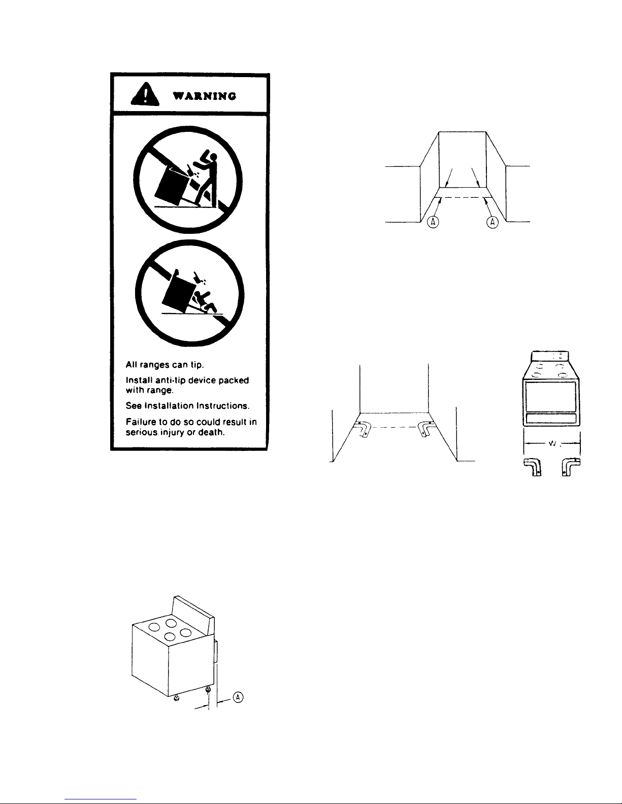
INSTALLATION INSTRUCTIONS
CABINET INSTALLATION OPENING FOR GAS
SLIDE-IN RANGE
A. Cabinet cutout must be prepared as shown in Figure
11. Never install a range over kitchen carpeting.
Figure 11
LO BACK RAIL SLIDE-IN MODEL
B. For electric and gas connection specifications refer to
instructions for installing automatic pilotless ignition
gas range.
C. On post formed (moulded) tops, shave the front
corner of cabinet opening flush with countertop in
area which will be underneath front corners of range
top (3/8"). (See Figure 12.)
Figure 12
D. On countertops with front metal trim, cut metal trim
back 3/8" from front corner of opening. (See Figure
--.)
and turned fully counterclockwise, the electrode between the flash tubes will start sparking and continue
as long as the knob is held in this position. After the
burner ignites, move the knob to the "ON" position of
the valve. At this time the sparking will cease. There
are no standing pilots that have to be lighted or
adjusted.
2. Top Burner Adjustment
The air shutter (see Figure 5) should be adjusted to a
proper flame. Loosen the air shutter lock screw and
adjust the air shutter so the flame has an inner cone
of bluish-green and an outer mantle of dark blue. The
flame should be soft in character. Tighten the lock
screw when the adjustment is complete.
Figure 14
NATURAL GAS BURNER ADJUSTMENT
Models with Sealed Top Burners (Below Serial
Number F0430127550)
1. Top Burners
Whenever a top burner gas valve knob is depressed
and turned fully counterclockwise, the electrode built
into the burner cap will start sparking and continue as
long as the knob is held in this position. After the
burner lights, move the knob to the "HI" position of the
valve. At this time the sparking will cease. There are
no standing pilots that have to be lighted or adjusted.
2. Top Burner Adjustment
No gas input adjustment is necessary as the burner is
equipped with a fixed orifice. There is no shutter to
adjust.
Figure 13
ADJUSTMENTS AND LP CONVERSION
NATURAL GAS BURNER ADJUSTMENT
Models Without Sealed Top Burners
1. Top Burners
Whenever a top burner gas valve knob is depressed
RC231002 Rev. 3 12
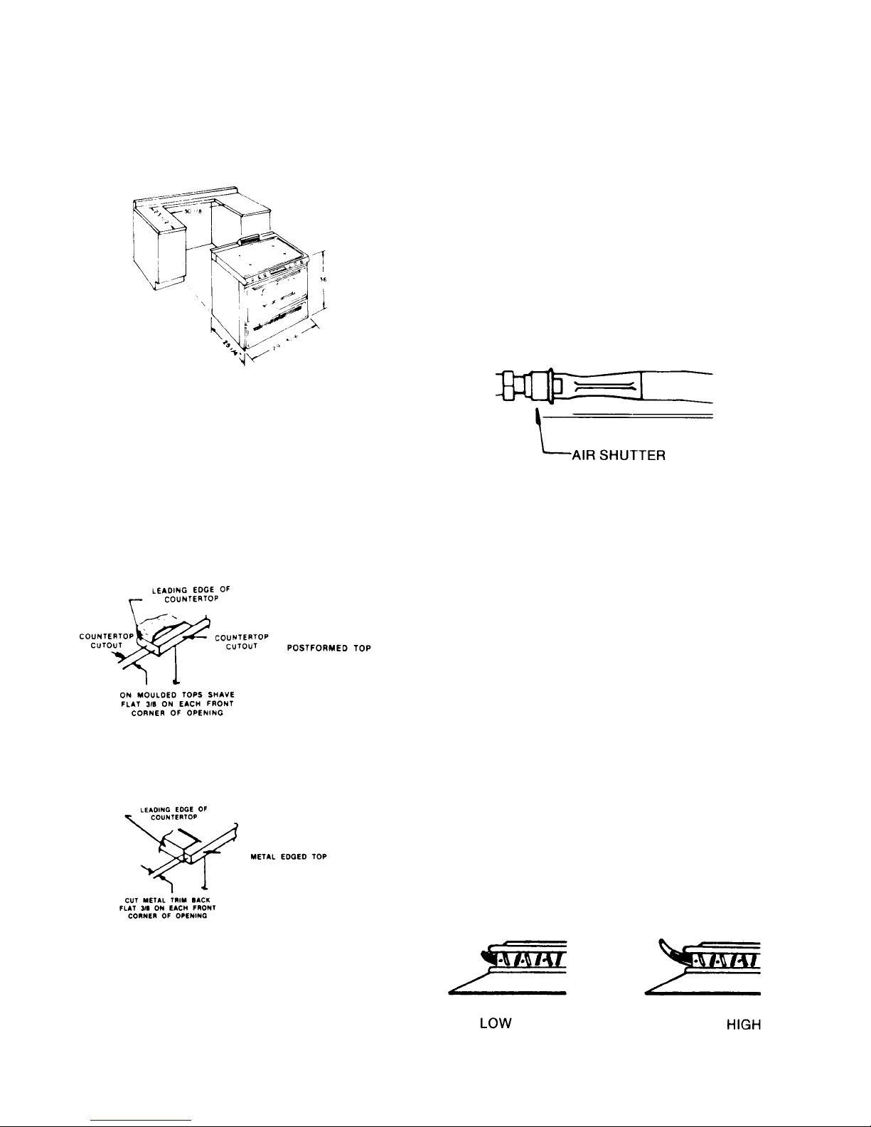
Low burner flame may be adjusted by turning adjustment screw in center of valve stem. Normally, the low
flame should be adjusted to the minimum steady blue
flame. Check the adjustment by turning from high to
low several times to see that the burner does not go
out.
Figure 15
Top Burner Setting
OR

INSTALLATION INSTRUCTIONS
Models with Sealed Top Burners (Above Serial
Number F0430127550)
The air shutters (see Figure 6) should be adjusted for a
proper flame. Adjust the air shutter so that the flame has
an inner cone of bluish-green and an outer mantle of dark
blue. The flame should be soft in character. To adjust the
air shutter to close the opening to decrease the air or
enlarge the opening for more air. Tighten the lock screw
when the adjustment is complete.
Low burner flame may be adjusted by turning adjustment
screw in center of valve stem. Normally, the low flame
should be adjusted to the minimum steady blue flame
(approximately 1/4" flame length). Check the adjustment
by turning from high to low several times to see that the
burner does not go out.
Figure 17
LOWER OVEN BURNER - RST
The appearance of properly adjusted oven burner flame is
a bluish-green inner cone and a dark blue mantle. The
flame characteristics should be clean and soft with no
yellow tips. Blowing or lifting of the flame should not occur.
Figure 16
Models with Cast Top Burners
The air shutters (See Figure 7) should be adjusted for a
proper flame. Adjust the air shutter so the flame has an
inner cone of bluish-green and an outer mantle of dark
blue.
For Access to the Air Shutters:
Lift off four (4) burner caps. Remove one (1) screw at each
burner body. Pull each burner body upwards and disconnect the ignition wire at the electrode. Remove one (1) flat
headed screw at each burner and lift off main top. Remove
plenum box covers (when so equipped).
To Adjust the Air Shutter:
Loosen the lock screw. Move the air shutter to close the
opening to decrease the air or enlarge the opening for more
air. Tighten the lock screw when the adjustment is complete.
Low burner flame may be adjusted by turning adjustment
screw in center of valve stem. Normally, the low flame
should be adjusted to the minimum steady blue flame
(approximately 1/4" flame length). Check the adjustment
by turning from high to low several times to see that the
burner does not go out. (See Figure 8.)
1. An electric ignitor is used to light the burner. DO NOT
attempt to insert any object into the opening of the protective shield surrounding the ignitor coil. Do not attempt to
clean this area.
2. The burner flame should be 1/2" long when the air
shutter is correctly adjusted. (See Figure 8.) The air
shutter is located at the lower right of the access area,
above the gas valve. To adjust the air shutter, loosen the
lock screw. Move the air shutter to close the opening to
decrease the air or enlarge the opening for more air.
Tighten the lock screw when the adjustment is complete.
Figure 18
UPPER OVEN BURNER ADJUSTMENT - RST
The burner flames should be 3/8" long when the air shutter
is correctly adjusted. The air shutter is located at the left
side of the upper oven burner. To adjust the air shutter,
loosen the lock screw. Move the air shutter to close the
opening to decrease the air or enlarge the opening to
increase the air. Tighten the lock screw when the adjustment is complete.
13 RC231002 Rev. 3
INSTALLATION INSTRUCTIONS
BROIL BURNER
Burner Adjustment
1. No gas input adjustment is necessary as the infrared
burner is equipped with a fixed orifice. There is no air
shutter to adjust.
2. An electric ignitor is used to light the burner. DO NOT
attempt to insert any object into the openings of the
protective shield surrounding the ignitor coil. Do not
attempt to clean this area.
3. The burner may have a hazy or fuzzy appearance
when in operation. This haze may be 3/8" thick
maximum and is normal for this type of burner.
UPPER OVEN FLAME CHARACTERISTIC
ADJUSTMENT
The appearance of a properly adjusted gas flame is one
having an inner cone of bluish-green and an outer mantle
of dark blue. The length of the inner cone flame will be
about 3/8" when correctly adjusted. (See Figure 9.) Flame
characteristics should be clean but soft.
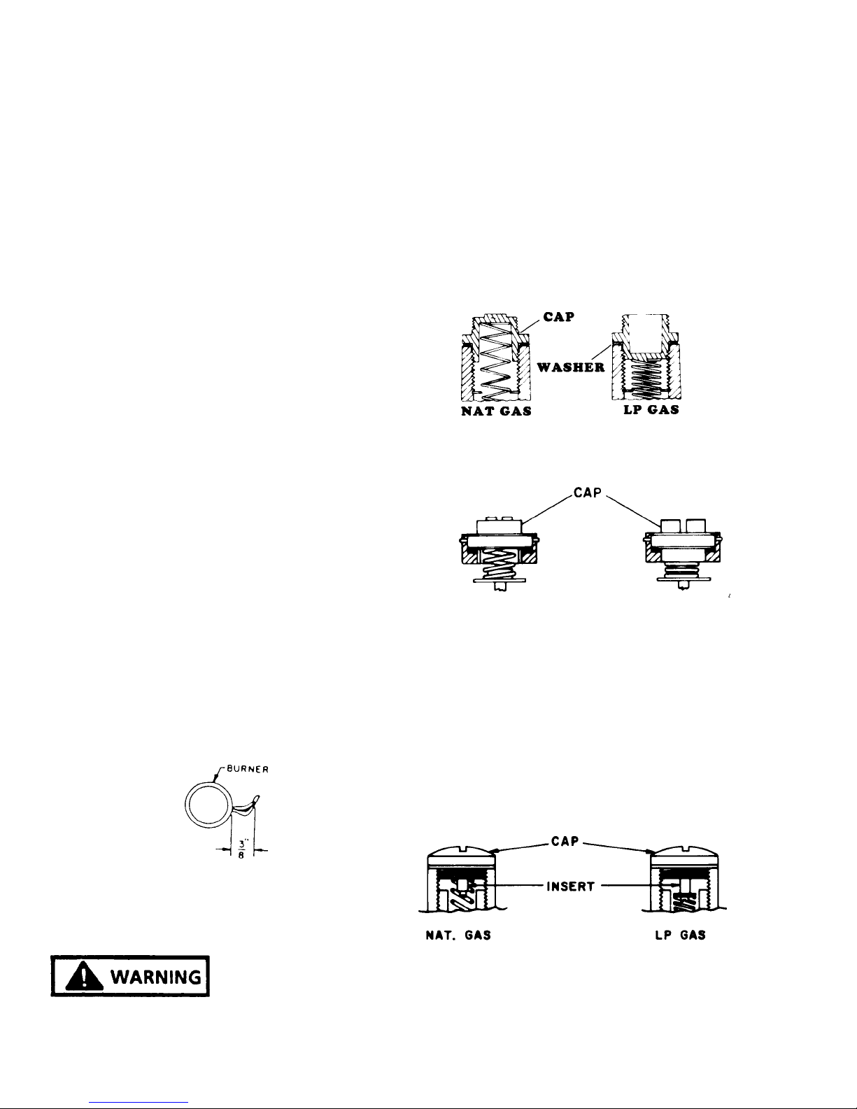
PRESSURE REGULATOR (On Range)
Remove the cap marked "Nat" and reverse it to read "LP".
Be sure not to disturb or remove the spring beneath the
cap. Also make sure the fiber washer is between the cap
and the body of the regulator. See Figure 10 for the
correction position of the cap.
Remove the cap with the screwdriver slot and replace
upside down. This plug will then have the marking "LPG10".
Be sure not to disturb or remove the spring beneath this
plug. See Figure 11 for correct position of plug.
Figure 20
OR
1. An electric ignitor is used to light the burner. DO NOT
attempt to insert any object into the openings of the
protective shield surrounding the ignitor coil. Do not
attempt to clean this area.
2. Oven Burner Adjustment
The burner flame should be 3/8" long when the air
shutter is correctly adjusted. (See Figure 9).
The air shutter is located at the left side of the upper oven
burner. To adjust the air shutter loosen the lock screw.
Move the air shutter to close the opening to decrease the
air or enlarge the opening to increase the air. Tighten the
lock screw when the adjustment is complete.
Figure 19
LP CONVERSION
Figure 21
OR
Remove the cap with the screwdriver slot. Remove the
black insert marked "Nat" from the cap. (This is a tight fit
in the cap.) Reverse this insert and carefully push it firmly
into the hole in the cap. The marking "LP" will now be
showing on the insert. Be sure the insert is pressed into the
shoulder. Also, be sure not to disturb the spring in the body
of the regulator.
Replace the cap in the body of the regulator and tighten.
See Figure 12 for the correct position of the insert.
NATURAL TO LP GAS CONVERSION
FIRE OR EXPLOSIION
HAZARD
THIS UNIVERSAL RANGE IS PREADJUSTED FOR
OPERATION ON "NATURAL" GAS AS SHIPPED FROM
THE FACTORY. TO USE THE APPLIANCE ON LP GAS,
YOU MUST DO THE FOLLOWING:
RC231002 Rev. 3 14
Figure 22
Remove the cap with screwdriver slot. Carefully remove
the spring and washer (washer will be at bottom of spring).
Reverse so that washer is at top of spring and reinstall
spring and washer.
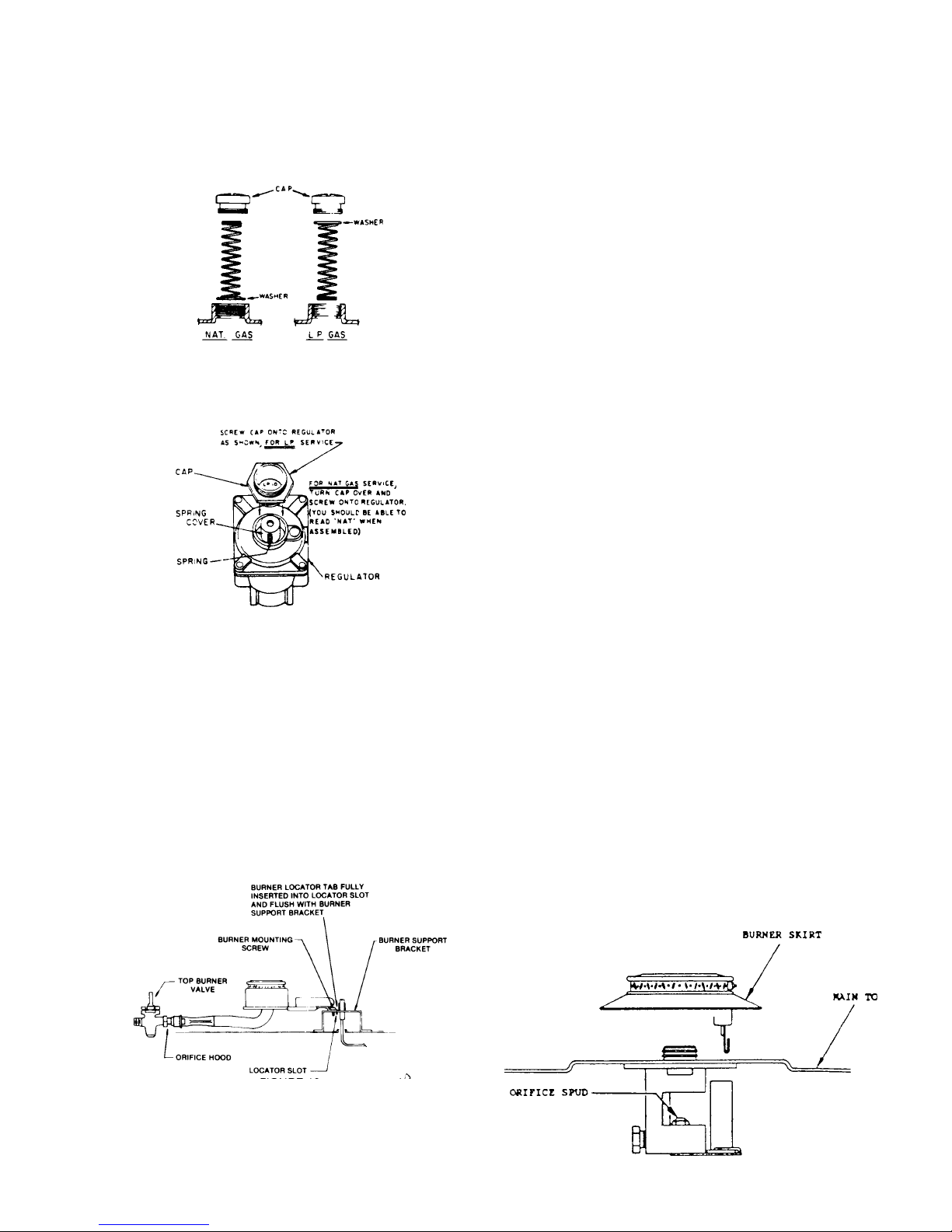
INSTALLATION INSTRUCTIONS
Remove the cap in the body of the regulator, over the
washer and spring, and tighten cap. See Figure 13 for the
correct position of the washer and spring.
Figure 23
OR
Figure 24
FLAME APPEARANCE
The air shutter (see Figure 17) should be adjusted for a
proper flame. Adjust the shutter so the flame has an inner
cone of bluish-green and an outer mantle of dark blue. The
flame should be soft in character.
NOTE: On LP gas a slight yellow tip will be visible on top
burner flames, but will not affect burner performance.
MODELS WITH SEALED TOP BURNERS
NOTE: Sealed Top Burner Models with Serial Number
Date Codes F006 through F009 are for use on Natural Gas
only and are not field convertible for use on LP gas.
TOP BURNER ADJUSTMENT (Below Serial Number
F0430127550)
ORIFICES
Universal Models (Natural or LP) are shipped from the
factory orificed for Natural Gas. IF THEY ARE TO BE
USED ON LP GAS, the burner orifice spuds must be
changed. They will be found wired to the inlet pipe behind
the storage drawer. The proper orifice for use on Bottled
(LP) Gas is red colored and stamped #68 (drill size). BE
SURE to use proper burner spud for the gas in use. Rewire
the Natural Gas orifice spuds to the inlet pipe for future
conversion.
MODELS WITHOUT SEALED TOP BURNERS
TOP BURNER ADJUSTMENT
ORIFICES
Remove four (4) top burners by removing the mounting
screws and lifting out of bracket. Then turn down the orifice
hoods onto the pins being careful not to drive pin into the
valve or to distort the hole through the center of the pin.
Reinstall the top burners and mounting screws. (See
Figure 15.)
FIGURE 25
Nat. Gas LP Gas
Burner Spud 54 68
(Red colored for
identification)
TO CONVERT
Remove four (4) top burners by pulling upwards. (See
Figure 26.) Remove the two (2) flat headed screws at each
burner and lift off main top. Replace the burner orifice
spuds using a 5/16" nut driver. Reinstall maintop and
burners. To replace the burners, position the ignitor over
the hole at the rear of each burner opening and push the
burner down onto the burner base until the skirt contacts
the maintop.
15 RC231002 Rev. 3
Figure 26

INSTALLATION INSTRUCTIONS
BURNER ADJUSTMENT
No gas input adjustment is necessary as the burner are
equipped with fixed orifices. There are no shutters to
adjust. NOTE: On LP gas a slight yellow tip will be visible
on top burner flames, but will not affect burner performance.
OR
TOP BURNER ADJUSTMENT (Above Serial Number
F0430127550)
TO CONVERT
Lift off four (4) burner caps. (See Figure 27.) Remove one
(1) screw at each burner body. Pull each burner body
upwards and disconnect the ignition wire at the electrode.
Mark wires for identification on reassembly. Remove one
(1) flat headed screw at each burner and lift off main top.
Remove plenum box covers (when equipped). Remove
two (2) screws from each venturi mounting bracket and
remove venturi assemblies.
Turn the orifice hoods onto the pins. The orifices should be
turned snug onto the pins careful not to drive pin into the
valve or distort the hole through the center of the pin.
Reinstall the burner bodies and caps.
Remove one (1) flat headed screw at each burner and lift
off main top.
Remove plenum box covers. Remove two (2) screws from
each venturi mounting bracket and remove venturi assemblies.
Turn the orifice hoods onto the pins. The orifice should be
turned snug onto the pins careful not to drive pin into the
valve or distort the hole through the center of the pin.
Reinstall the burner bodies and caps.
The air shutters should be adjusted for a proper flame.
Adjust the air shutter so that the flame has an inner cone
of bluish-green and an outer mantle of dark blue. The
flame should be soft in character. To adjust the air shutter,
loosen the lock screw. Move the air shutter to close the
opening to decrease the air or enlarge the opening for more
air. Tighten the lock screw when the adjustment is complete. Reinstall the plenum box covers, main top and main
top burners in reverse order of removal. NOTE: On LP
gas a slight yellow tip will be visible on top burner
flames, but will not affect burner performance.
Figure 27
MODELS WITH CAST BURNERS
TO CONVERT
Lift off four (4) burner caps. (See Figure 28.) Remove one
(1) screw at each burner body. Pull each burner body
upwards and disconnect the ignition wire at the electrode.
RC231002 Rev. 3 16
Figure 28
OVEN BURNER (Upper and Lower Oven) (RST)
ORIFICES
Turn down the orifice hood onto the pin. The orifice should
be turned snug onto the pin being careful not to drive pin
into the valve or to distort the hole through the center of the
pin.
LOWER OVEN FLAME CHARACTERISTIC
ADJUSTMENT
The appearance of a properly adjusted oven burner flame
is a bluish-green inner cone and a dark blue mantle. The
flame characteristics should be clean and soft with no
yellow tips. Blowing or lifting of the flame should not occur.
The burner flame should be 1/2" long when the air shutter
is correctly adjusted. (See Figure 18.)
An electric ignitor is used to light the burner. DO NOT
attempt to insert any object into the openings of the
protective shield surrounding the ignitor coil. Do not
attempt to clean this area.
INSTALLATION INSTRUCTIONS
found under the plate in the center of the burner box. BE
SURE to use the proper burner spud for the gas in use.
Reinsert Nat. Gas orifice in burner box with louvers facing
to rear of unit.
Nat. Gas LP Gas
Burner Spud 50 58
(Silver colored for identi-
Figure 29
fication)
The air shutter is located in the lower access area. To
adjust the air shutter, loosen the lock screw. Move the air
shutter to close the opening to decrease the air or enlarge
the opening for more air. Tighten the lock screw when the
adjustment is complete.
OVEN BURNER (RSS)
1. Orifices
Turn down the orifice hood onto the pin. The orifice
should be turned snug onto the pin being careful not
to drive pin into the valve or to distort the hole through
the center of the pin.
2. Low Oven Flame Characteristic Adjustment
a. The appearance of a properly adjusted oven burner
flame is a bluish-green inner cone and a dark blue
mantle. The flame characteristics should be clean
and soft with no yellow tips. Blowing or lifting of the
flame should not occur. The burner flame should be
1/2" long when the air shutter is correctly adjusted.
b. An electric ignitor is used to light the burner. DO
NOT attempt to insert any object into the openings of
the protective shield surrounding the ignitor. Do not
attempt to clean this area.
MODELS WITH SEALED TOP BURNERS
Universal models (Nat. or LP) are shipped from the factory
orificed for Nat. Gas. IF THEY ARE TO BE USED ON LP
GAS, the burner orifice spud must be changed. This will be
found wired to the inlet pipe behind the storage drawer.
The proper orifice for use on Bottled (LP) gas is silver
colored (Nickel plated) and stamped #58 (drill size). BE
SURE to use the proper burner spud for the gas in use.
Rewire the Natural Gas orifice spuds to the inlet pipe for
future conversion.
TO CONVERT
Remove oven door and storage drawer. Shut off valve on
gas line that runs from the pressure regulator to the gas
valve.
Remove the two (2) screws fastening the broiler burner to
the oven tank at front of burner. Remove the burner by
pulling front end down to expose the burner orifice spud in
the rear wall. Be careful not to break the ignitor. Lay the
burner aside carefully with the screen side up. Replace the
burner orifice spud using a 5/16" nut driver. Reverse the
procedure to reinstall the burner.
BURNER ADJUSTMENT
c. The air shutter is located in the lower accessed
area. To adjust the air shutter, loosen the lock screw.
Move the air shutter to close the opening to decrease
the air shutter to close the opening to decrease the air
or enlarge the opening for more air. Tighten the lock
screw when the adjustment is complete.
ULTRA-RAY® BROILER BURNER
An electric ignitor is used to light the burner. DO NOT
attempt to insert any object into the openings of the
protective shield surrounding the ignitor element. Do not
attempt to clean this area.
MODELS WITHOUT SEALED TOP BURNERS
Universal models (Nat or LP) are shipped from the factory
orifices for Nat gas. IF THEY ARE TO BE USED ON LP
GAS, the burner orifice spud must be changed. This will be
No gas input adjustment is necessary as the infrared
burner is equipped with a fixed orifice. There is no shutter
to adjust.
The burner may have a hazy or fuzzy appearance when in
operation. This haze may be 3/8" thick, maximum and is
normal for this type of burner.
RANGE FEATURE CHECKOUT
Check all range features, including lights, clocks, etc. for
proper operation.
17 RC231002 Rev. 3

INSTALLATION INSTRUCTIONS
CHECKOUT PROCEDURE OF CLEAN CYCLE
OPERATION - RSS (WITH MECHANICAL TIMER;
FOR OTHER MODELS FOLLOW TIMER
INSTRUCTIONS)
REMOVE OVEN RACKS, BROILER PAN AND GRID.
MAINTENANCE INSTRUCTIONS
1. Keep appliance clear and free from combustible
materials, gasoline, cleaning fluids, and other flammable vapors and liquids.
A. Set the range clock to the correct time of day. (If not
set properly).
B. Push the turn the start dial on the backguard to the
approximate time of day until set stem pops out.
C. To establish length of clean time, turn the stop dial 1
1/2 hours to 2 hours ahead of start time. On electronic
clock models push clean button on timer for 3-hour
clean time.
D. Close and latch oven door, moving the latch arm to
the far right. (clean position).
E. Turn the oven heat control, on control panel, clock-
wise to "CLEAN" position. Then, turn selector switch
to the "CLEAN" setting.
F. A 15-20 second delay should occur, and the oven
indicator light should then come on.
G. After the cycle begins, the oven should reach a
temperature in excess of normal broiling (approximately 700°). The "CLEAN" indicator light should
come on, and the terminal lock system should lock
and secure the oven door.
H. Turn selector switch from "CLEAN" to "OFF" and heat
control to "OFF".
I. When oven temperature has lowered to approxi-
mately 700° or less, the lock system should unlock the
oven door allowing the latch handle to move freely.
2. Gas burners need sufficient air to operate. Objects
should not be placed in front of or on maintop rear of
range while in use. This could obstruct the air flow
needed for combustion and vent for flue products.
BURNER CLEANING -
The burner heads are made of aluminum and should not be
subjected to scouring or abrasive pads. Never not be
subjected to scouring or abrasive pads. Never use steel
wool or oven cleaners on the burner heads or they will dull
and not regain their original luster.
To clean the burners, remove the burner grates and push
the main top towards the rear of the range until the front
tabs are free. Then raise the main top and remove or
engage the main top support. This will support the main top
while the burners are removed for cleaning.
Before attempting to remove the burners, be certain the
four (4) burner mounting screws which retain the burners to
the burner supports are removed. If the screws are still
secured, they can be removed with a Phillips screwdriver.
To remove the burners, release the burner head brackets
from the burner support, lift up and pull towards the rear of
the range.
To replace the burners slip the Venturi (long, thin end) over
the burner orifice and then position the burner locating
brackets into the burner support channel. Reinstall the
burner mounting screws.
DEFECTS
Any defects or faulty or damaged parts must be reported
immediately and steps taken to correct them through
normal dealer service channels.
POWER FAILURE
In the event of a power failure, safe manual lighting of the
top burners is possible. To do this, hold a lighted match at
the desired burner head (the part projecting above the
main top), turn the top burner control knob to the light
position.
The flame height can now be adjusted to the desired size.
The broil and oven burners cannot be operated during a
power failure and no attempt should be made to do so.
RC231002 Rev. 3 18
Wiping the burners following each use will remove spillover
deposits and grease spatters before these soils get a
chance to harden on the surface. Burnt soil can be cleaned
by soaking the burners in warm water and a dishwashing
liquid detergent such as "Dove" or "Lux". A dishcloth or
nonabrasive pad (such as Dobie pad) should be used to rub
the burner caps after the soaking period. Be sure the
burners are dry, as water lodged in the burner parts might
cause an uneven flame or interfere with automatic lighting.
If stains still remain after soaking, you can soak any heavily
soiled burners in a solution of two tablespoons of "Dip-it"
per quart of water. Use a large pan and enough water so
the cap and base part of the burner assembly can be
completely immersed; bring water to a boil, remove vessel
from burner, and add measured amount of "Dip-it". Immerse the burner in the hot solution and soak for 20

INSTALLATION INSTRUCTIONS
minutes, no longer. Be sure the liquid completely covers
the cap and base portion of the assembly. After 20
minutes, remove burner, cool slightly and rinse thoroughly
with cold water. Be sure hands are protected to prevent
burns from hot water. Be sure all the solution is completely
rinsed off both the inside and outside of the burner. If some
stains still remain, rub with a "Dobie" pad.
The burner may then be left to dry at room temperature or
be placed in the oven at 170° for 1/2 hour. BE SURE TO
PROTECT YOUR HANDS WHEN REMOVING DRIED
BURNERS FORM THE OVEN.
Figure 31
NOTE: These thermostats (Robertshaw) have a cement
coating over the adjusting screw. Evidence of attempts to
adjust these thermostat nullifies the warranty.
UNIVERSAL GAS ORIFICES
With the exception of the Broiler Burner and Sealed Top
Burner, orifices for these models are of the coaxial type.
They contain a double coaxial orifice hood and universal
pin. The hood orifice is sized for Natural Gas (6 inches
water column pressure). The pin orifice is sized for LP Gas
(11 inches water column pressure).
The orifice is adjusted for Natural gas as shipped from the
factory. It must be adjusted for use on LP gas. This
requires that the orifice hood be screwed or turned down
approximately two (2) turns onto the pin. The hood should
be turned down snug but not tight to the point where it
damages or distorts the pin. (See Figure 19.)
When set up for Natural Gas, gas flows around the pin and
through the orifice of the hood which is sized for Natural
Gas. When the hood is screwed down for LP gas, the gas
flow is only through the hollow pin which is sized for LP gas.
For Thermostat Calibration on models with the Electronic Range Control (ERC), see section on ERC
Operating and Testing Procedures.
When making any temperature adjustments, a reliable test
instrument should be used to accurately determine the
oven temperature.
A reliable test instrument of the thermocouple type is
preferred which will allow temperature readings with the
door closed.
Position the thermocouple clip of the test instrument on the
center of the oven rack that is positioned in the center of the
oven cavity. The thermocouple of the test instrument
should be "weighted" or "loaded" in order to represent more
closely the average cooking temperature of the oven
versus the on-off cycling of the thermostat with the full rate
gas valve. The procedure for loading a thermocouple is
illustrated in Figure 20.
Figure 30 - Universal Orifice
OVEN THERMOSTAT KNOB ADJUSTMENT
Models without electronic Range Control (ERC)
Cooking recipes are written to take into consideration that
oven thermostats have manufacturing tolerances, and
may not provide an average temperature exactly on the
thermostat setting. If the temperature average reading is
beyond the ±25° tolerance range, a limited adjustment can
be made with the adjustable skirt on the knob. The
adjusting screw on the thermostat is sealed and no adjustment can or should be attempted. The rear of the adjustable skirt shown here is self-explanatory.
Figure 32 - "Loading" A Thermocouple
An 8 1/2 x 11-inch piece of aluminum foil should be folded
five (5) times, doubling the thickness with each fold. After
the fifth fold, place the thermocouple in the center of the
aluminum piece as shown and fold once more. Finally, fold
the sides so the foil clings to the thermocouple. The loaded
thermocouple will then provide temperature readings on
the thermometer that more closely resemble the mean or
average temperature of the oven as it cycles on and off
above and below the temperature setting.
With all the controls properly set for "Bake", turn the oven
thermostat to 350°.
19 RC231002 Rev. 3
INSTALLATION INSTRUCTIONS
After the oven has cycled for 25 to 30 minutes, note the
temperature that the oven cycles ON and OFF. For
example, at 350° setting the oven cycles between 335° and
355°. This provides a mean or average temperature of
345°F., well within the ±25°F specification.
GAS PRESSURE
Correct ignition and operation of the burners are dependent
upon adequate gas pressure. The regulator is designed to
provide pressure of approximately six (6) inches water
column pressure (WCP) for natural gas and approximately
eleven (11) inches for WCP for liquid propane (LP) gas,
provided the universal type gas regulator and gas valves
have been correctly set up for the type gas employed.
These pressures therefore require that the minimum supply
pressure to the regulator must be at least six (6) inches
WCP for natural gas and eleven (11) inches WCP for LP
gas, with maximum pressure not to exceed fourteen (14)
inches WCP.
MEASURING GAS PRESSURE
Equipment for measurement of gas pressure varies from
pressure meters and gauges to the relatively simply and
most commonly used manometer. If it is used, follow the
directions supplied with the unit. The following informations
covers the use of a manometer.
zero level.
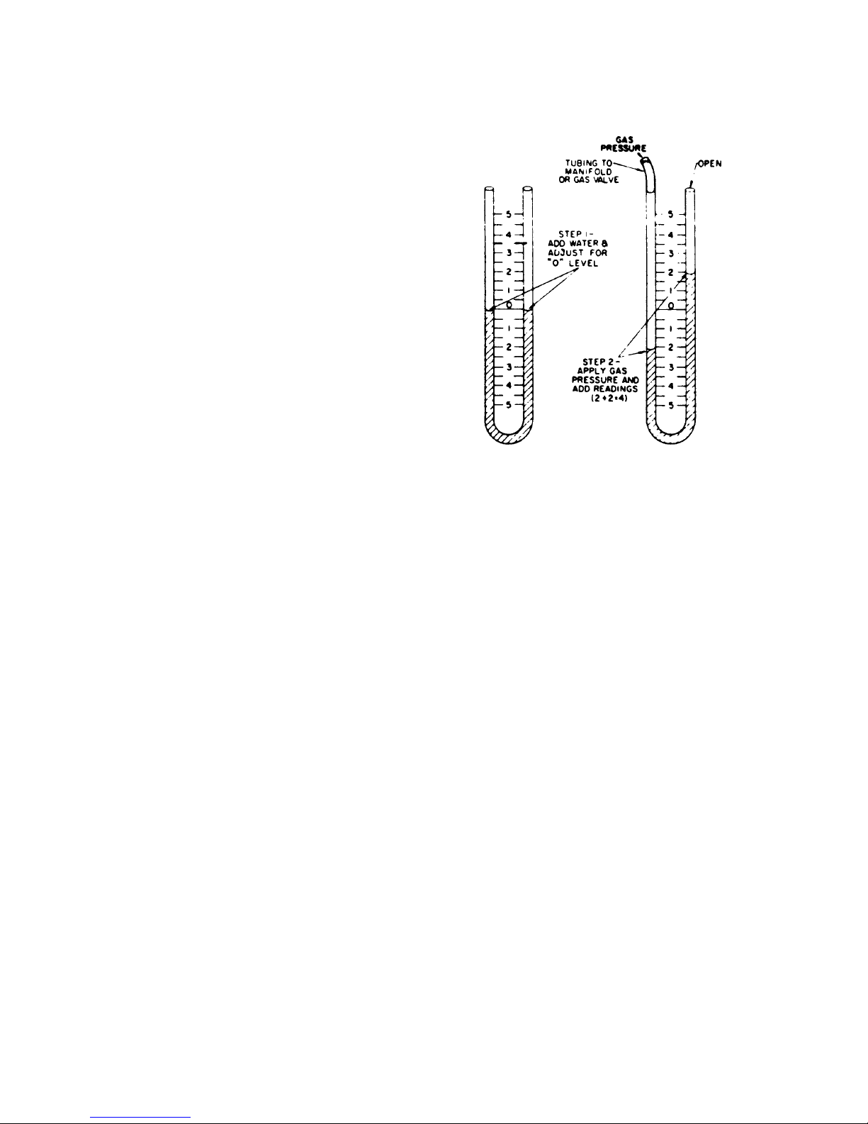
Figure 33 - The Mannometer
A manometer is simply a U-shaped tube of clear plastic or
glass (see illustration). A scale in inches is located between
the two (2) legs of the "U". In use, the tube is filled with
sufficient water to achieve a level at "0" inches. One end
of the tube is connected to the range manifold or gas valve
orifice while the other end of the tube or leg is open. When
gas pressure is applied, the water on the gas side of the tube
is pushed down and the water in the other leg rises up
against the atmospheric pressure on the open end. The
sum of the readings below the zero level and above the
level will provide the gas pressure in inches water column,
or the water column height which the gas pressure will
support against the atmospheric pressure on top of the
water column. The manometer therefore indicates gas
pressure in inches water column. This conforms with the
gas specifications for gas appliances which are given as
inches WCP or inches water column pressure.
USING THE MANOMETER
The usual procedure for taking the pressure reading is to
connect the tubing to one of the gas valve orifice hoods and
turn on the valve. A full load reading should be taken by
turning on all of the top burners and the oven burner to
assure that the pressure under a full load is adequate.
Figure 33 shows four (4) inches water column pressure
(WCP), two (2) inches above and two (2) inches below the
RC231002 Rev. 3 20
SAFE OPERATING PROCEDURES
SAFETY PRECAUTIONS READ BEFORE OPERATING
THE RANGE.
are easily hit. UTENSIL HANDLES SHOULD BE
TURNED INWARD AND NOT EXTEND OVER ADJACENT SURFACE BURNERS to minimize burns,
ignition of flammable materials, and spillage due to
unintentional contact with the utensil.
Accidents are always tragic, especially because so many
of them could have been prevented with a little care and
judgement. Here are some basic good practices to follow
for safe use of the gas range.
1. Be sure the range is installed by a qualified technician
and is properly grounded.
2. Never use the range for warming or heating the room.
This warning is based on safety considerations.
3. Wear proper apparel - loose fitting or hanging
garments should never be worn when operating the
range.
4. Do not repair or replace any part unless specifically
recommended in the manual. All other servicing
should be referred to a qualified service technician.
5. Flammable materials should not be stored near the
range.
6. Do not use water on grease fires. Smother fire or
flame or use dry chemical (such as baking soda) or
foam type extinguisher.
7. Use only dry potholders. Moist or damp potholders on
hot surfaces may result in burns from steam. Do not
use a towel or other bulky cloth.
8. Children should not be left alone or unattended in
area when the range is in use. They should never be
allowed to sit or stand on any part of the range.
9. Select utensils large enough to properly contain food
and avoid boil-overs or spillovers. This will both save
cleaning and prevent hazardous accumulations of
food, since heavy splattering or spillovers left on a
range can ignite. Pan size is especially important in
deep-fat frying.
12. Never leave range burners at high heat settings. Boilover causes smoking and greasy spillovers that may
ignite.
13. Clean range with caution. If a wet sponge or cloth is
used to wipe spills on a hot cooking area, be careful
to avoid steam burns. Some cleansers can produce
noxious fumes if applied to hot surfaces.
14. Do not touch surface area near burner units and
burner caps. During and after use, these areas may
be hot enough to cause burns. Avoid contact with
these areas by clothing or other flammable materials
until they have had sufficient time to cool.
15. Do not heat unopened food containers - build-up of
pressure may cause container to burst and result in
injury.
16. Do not store items of interest to children in
cabinets above the range. Children climbing on
the range to reach items could be seriously injured.
17. GREASE - Grease is flammable and should be
handled carefully. Never leave any cooking operation unattended. Let fat cool before attempting to
handle it. Wipe spillovers immediately.
18. Burner flame should be adjusted so that they do not
extend beyond the edge of the utensil. This warning
is based on safety considerations.
19. Never sit, step, or stand on any part of the range or
injury may result.
10. TYPE OF UTENSILS - Avoid pans that are unstable
and easily tipped. In choosing pans, look for easily
grasped handles that will stay cool. Pans that are too
heavy when filled with food can also be a hazard. If
pan handles twist and cannot be tightened, discard
the pan.
11. HANDLES - Always turn pan handles to the side or
back of the range - not out into the room where they
21 RC231002 Rev. 3
SAFE OPERATING PROCEDURES
OPERATING INSTRUCTIONS
SAFETY TIPS
Some "common sense" rules to remember:
· Always be certain that the oven parts are cool before
touching them when hands are not protected by a
potholder.
· Always use a dry potholder, never a moist one, nor a
trailing cloth, to avoid possible burns from steam.
· Pulling out oven racks is a convenience when lifting
heavy foods, but caution should be used against
possible burns from touching hot surface.
· For your safety, never use the range as a space
heater.
· Do not heat unopened containers such as jars, cans,
etc., in the oven. The build-up of pressure may cause
the container to burst and can cause serious personal
harm or damage the range.
· Do not use aluminum foil on the racks or oven bottom.
This will hinder heat circulation.
· Do not use aluminum foil on the racks or oven bottom
when cleaning. The self-cleaning feature makes this
unnecessary.
· Do not attempt to clean the oven or broiler burner
ignitor assembly. The ignitors are electrically operated and the danger of electric shock is present.
· Do not place baking utensils directly on the oven
bottom.
· Do not use disposable or substitute broiler pans. The
broiler pan and grid provided with the range have
been scientifically designed to keep drippings cool so
they will not become hot enough to ignite.
· Always remove the broiler pan and grid from the oven
when baking and roasting. A possible fire hazard
could exist if a soiled pan and grid are left in the oven.
Also, any drippings on the grid will become baked on
and will be very difficult to remove.
· Never cover the broiler grid with aluminum foil. It may
trap grease and cause it to smoke. If desired, place
a sheet of aluminum foil to line the broiler pan
underneath the broiler grid to ease clean up. (A cup
of water placed in the broiler pan will also minimize
clean up.)
· Never use the range as storage space.
· Never store flammable items in the storage drawer.
all broiling is done with a fast, searing heat, no temperature
selection is used except with certain recipes). The burner
lights automatically in 50 - 60 seconds. During the broil
cycle the burner will cycle on and off. For programming
information on models with the Electronic Range Control,
see Section III, Operation and Troubleshooting, ERC
Control.
Things to Remember:
CLOSE THE DOOR COMPLETELY FOR ALL BROILING.
Ultra-Ray® consumes most smoke and spatter. Kitchen
stays cleaner, cooler.
DO NOT PRE-HEAT THE BROILER BEFORE USING.
BAKING
For best results preheat the oven first. Turn the selector
dial to "Manual" and the thermostat dial to the desired
temperature. The oven will light automatically. Allow the
oven to heat to temperature, approximately fifteen (15)
minutes. For programming information on models with the
Electronic Range Control, see Section III, Operation and
Troubleshooting, ERC Control.
The range is equipped with tilt proof oven racks with
automatic stops. The oven racks are removable and can
be inserted at various levels. They can be pulled to the
"STOP" position without danger of tipping. To remove the
racks, pull to the stop position, raise the forward edge, and
lift. Reverse the procedure to install racks. One or both
oven racks can be used during baking.
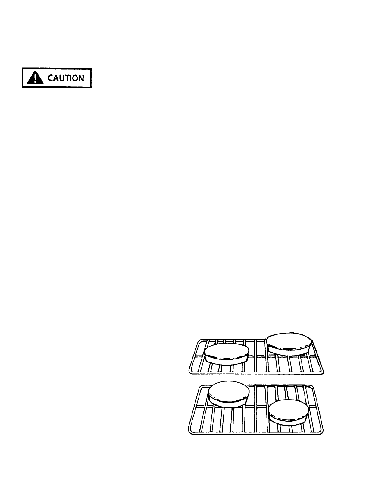
Always keep in mind that heated air in the oven must be
allowed to circulate freely. Leave at least 1 1/2" between
utensils and between utensils and the oven walls. For
example, never place one cake layer directly over another
- stagger them within the oven.
BROILING
The Ultra-Ray® Broiler
To use the Ultra-Ray® broiler, set the selector dial to
"Manual" and the temperature control dial to "Broil" (since
RC231002 Rev. 3 22
FIGURE 34

SAFE OPERATING PROCEDURES
OPERATING THE TOP BURNERS
MODELS WITHOUT SEALED BURNERS
The top burners of some models are equipped with Tri-Set
top burner valves. These valves provide flame adjustment
for any size flame which is desired as well as "click"
positions for "LO", "MED", and "HI" settings. Depress the
knob and turn the knob counterclockwise as far as it will go.
When the burner lights, turn the knob back to the desired
flame height.
The "HI" position provides a flame which will bring water to
a full boil quickly. This is the "full on" position of the valve.
If the burner flame is turned down, an audible "click" can be
heard as the valve reaches the "MEDIUM" position. This
flame is sufficient to keep water boiling in a covered pan.
When the flame is turned down lower, a second "click" can
be heard. This is a very low or "Keep Warm" flame setting
which is the "LO" position on the valve. The low flame
provides a warming heat to keep food which is already
cooked ready to serve.
The low burner flame may be adjusted by turning adjustment screw in center of valve stem. Normally, the low
flame should be adjusted to the minimum steady blue
flame. Check the adjustment by turning from high to low
several times to see that the burner does not go out.
NOTE: When adjusting the low burner flame, the valve
stem should be held in the "LOW" position.
The Tri-Set valves are equipped with metered, fixed
orifices, and the low setting cannot be adjusted. As there
are air shutters, the burner flames can be adjusted in
accordance with the Adjustment and Calibration Instructions.
The HI-LOW valves on other models are similar but
without the "click" stops.
TOP BURNERS
The top burners consists of a burner and integral cap, a
flash tube and support, a gas delivery tube including
venturi and an adjustment air shutter. These burners are
designed for trouble free operation with a minimum of
parts.
MODELS WITH SEALED BURNERS
The top burners of these models are equipped with Tri-Set
top burner valves. These valves provide flame adjustment
for any size flame which is desired as well as "click"
positions for "LO", "MED", and "HI" settings.
Whenever a top burner gas valve knob is depressed and
turned fully counterclockwise, the electrode built into the
burner cap will start sparking and continue as long as the
knob is held in this position. After the burner lights, move
the knob to the "HI" position of the valve. At this time the
sparking will cease. There are no standing pilots that have
to be lighted or adjusted.
23 RC231002 Rev. 3
OPERATION AND SERVICE PROCEDURES
(SLIDE IN MODELS)
ELECTRONIC CLOCK/TIMER
The Clock/Timer offers a time-of-day clock with a PM
designation, a Minute Timer with up to nine (9) hours and
fifty-nine (59) minutes, and cook and stop functions. The
clock and timer are set up with up and down variable speed
"slew" entry.
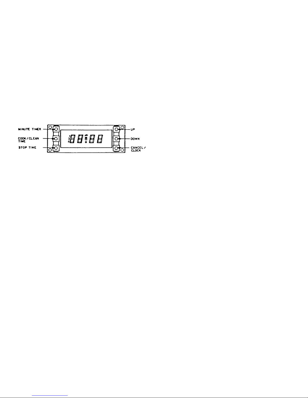
The display board consists of a vacuum fluorescent display
(VFD) with pushbutton entry. There are six (6) pushbuttons:
"MINUTE TIMER", "COOK/CLEAN TIME", "STOP TIME",
"UP" and "DOWN" and "CANCEL/CLOCK". The "UP" and
"DOWN" pushbuttons are for time setting.
Figure 56 - Electronic Clock/Timer
The Clock/Timer is a digital clock with a minute timer and
automatic control cooking cycle. The clock is set via the
function setting and slew controls. When power is connected to the unit, or a power failure of longer than three (3)
seconds occur, the display will show "12:00" flashing at the
rate of 1/2 second ON and 1/2 second OFF.
Setting the Time-of-Day
To Set the Minute Timer:
1. Display the "MINUTE TIMER" button. The timer will
display "0:00".
2. Press the "UP" button until the desired time period is
displayed, and release the "UP" button.
The minute timer is now programmed. After approximately five (5) seconds the timer display will revert
back to the Time-of-Day while continuing to count
down the programmed time. An alarm will sound
when the timer reaches "0:00". Press the "MINUTE
TIMER" button to silence the alarm. To check the
remaining time in the program, simply press the
"MINUTE TIMER" button.
The Minute Timer can also be used when the Clock/
Timer is programmed for a Timed Bake or Self-Clean
operation. NOTE: The Minute Timer does not control
oven operation.
SETTING TIMER FOR TIMED BAKE (Bake Cycle
Only)
SEMI-AUTOMATIC OPERATION
Oven starts at once and shuts off at the end of the cooking
cycles.
The clock setting is achieved by depressing the "CANCEL/
CLOCK" pushbutton first. Then key in the desired time of
day by using the "UP" and "DOWN" pushbutton keys. The
clock has a PM designation on the VFD for the PM time
setting.
The Clock/Timer also incorporates military timing capabilities. In order to change from the standard AM/PM clock
operation to military time clock operation or vice versa,
simultaneously press "COOK/CLEAN TIME" button and
the "STOP TIME" button. NOTE: The "UP" and "DOWN"
buttons must be pressed within five (5) seconds after
selecting or pressing any timing function button ("CANCEL/CLOCK", "MINUTE TIMER", "COOK/CLEAN TIME",
"STOP TIME"). If the "UP" and "DOWN" buttons are not
pressed within the five (5) second period, incorrect or no
programming will occur.
Setting the Minute Timer
The minute timer can be used for precisely time baking or
broiling operations in the oven. It can be used for timing
from one (1) minute up to nine (9) hours and fifty-nine (59)
minutes.
1. Turn selector switch knob to "AUTO".
2. Turn oven control knob to the desired baking temperature.
3. Press the "STOP TIME" button. The display will show
"0:00".
4. Press the "UP" button to set the desired stop time, and
then release the "UP" button. After approximately
five (5) seconds, the display reverts back to the Timeof-Day, "AUTO" appears on the left of the display
along with the oven indicator in the center of the
display signifying that the timed bake cooking cycle
has started. When the desired stop time is reached,
the oven indicator light goes out and an alarm will
sound for approximately ten (10) seconds. The oven
will automatically shut off. "AUTO" will continue to
blink ON and OFF indicating that the clock timer was
set for an automatic timed function and is completed.
5. Turn the selector switch to "MANUAL", oven control
to the OFF position and press the "CANCEL/CLOCK"
button.
RC231002 Rev. 3 24

OPERATION AND SERVICE PROCEDURES
(SLIDE IN MODELS)
DELAYED TIME BAKE
Oven starts at a later time and shuts off at the end of the
cooking cycle.
1. Turn selector switch knob to "AUTO".
2. Turn oven control knob to the desired baking temperature.
3. Press "COOK/CLEAN TIME" button. The display will
show "0:00".
4. Press the "UP" button to set the desired length of
baking time. EXAMPLE: To time bake for three (3)
hours press and hold the "UP" button until "3:00"
appears on the display, then release the UP button.
5. Press the "STOP TIME" button.
6. Press the "UP" button to set the desired stop time. To
have the time bake cycle finish at five o-clock (5:00),
press and hold the "UP" button until "5:00" appears on
the display, then release the "UP" button. After
approximately five (5) seconds, the display reverts
back to the Time-of-Day and "AUTO" appears on the
left of the display indicating that the Clock/Timer is
programmed for an automatic timed function. The
clock will automatically calculate the start time. When
the starting time is reached, the oven indicator in the
center of the display will come on indicating that the
timed bake cycle has started.
When the stop time is reached, the oven indicator
turns off and an alarm will sound for approximately
ten (10) seconds. The oven will automatically turn off
and AUTO will continue to blink ON and OFF indicating that the Clock/Timer was set for an automatic
timed mode and it is completed.
7. Turn the selector switch to "MANUAL", the oven
control to the OFF position, and press the "CANCEL/
CLOCK" button.
SETTING THE TIME FOR SELF-CLEAN
4. Press the "COOK/CLEAN TIME" button. The display
will show "0:00".
5. Press the "UP" button to set the desired length of the
clean time. EXAMPLE: To self-clean the oven for
three (3) hours, press and hold the UP button until
"3:00" appears on the display, then release the "UP"
button.
After approximately five (5) seconds, the display
reverts back to the Time-of-Day and "AUTO" appears
on the left of the display along with the oven indicator
in the center of the display signifying that the clean
cycle has started.
The oven indicator light on the control panel will come
on and cycle ON and OFF with the thermostat.
6. At the end of the clean cycle the oven indicator light
and oven indicator (clock) will turn OFF, and an alarm
will sound for approximately ten (10) seconds. The
oven will automatically turn off and "AUTO" will
continue to blink ON and OFF indicating that the
Clock/Timer was set for an automatic timed mode
and it is now completed.
7. Turn the selector switch to "MANUAL", the oven
control to "OFF" and press the "CLOCK/CANCEL"
button.
8. The oven door can be opened approximately 30
minutes after the completion of the clean cycle. Do
not attempt to open the oven door latch until approximately thirty (30) minutes have elapsed, otherwise
the door lock mechanism may be damaged.
If the door will not open, wait five (5) minutes and try
again.
TO START SELF-CLEAN LATER:
1. Turn the selector switch knob to the "AUTO" position.
2. Turn the oven control counterclockwise until it stops
("CLEAN" - turn to "STOP" position).
TO START SELF-CLEAN NOW:
1. Turn the Selector switch knob to the "AUTO" position.
2. Turn the oven control counterclockwise until it stops
("CLEAN - TURN TO STOP" position).
3. Move the latch lever to the right hand (self-clean)
position. The clean indicator will now come on.
3. Move the latch lever to the right hand ("SELF-CLEAN")
position. The clean indicator will now come on.
4. Press the "COOK/CLEAN" button.
5. Press the "UP" button to set the length of time desired
to self-clean the oven. For example, to self-clean up
to three (3) hours, press and hold the "UP" button until
"3:00" appears on the display, then release the "UP"
button.
25 RC231002 Rev. 3
OPERATION AND SERVICE PROCEDURES
(SLIDE IN MODELS)
TO AVOID THE RISK OF ELECTRIC SHOCK, PERSONAL INJURY OR DEATH DISCONNECT POWER
BEFORE SERVICING, UNLESS TESTING REQUIRES IT.
6. Press the "STOP TIME" button.
7. Press the "UP" button to set the desired stop time of
the self-clean cycle. For example, to have the selfclean end at 4 o'clock, press and hold the "UP" button
until "4:00" appears on the display, then release the
"UP" button. After approximately five (5) seconds,
the display will revert back to the Time-of-Day and
"AUTO" will appear on the left of the display indicating
the "CLOCK/TIMER" is programmed for an automatic timed operation. The clock will automatically
calculate the start time of the self-clean cycle. In
other words, a three (3) hour self-clean cycle would
begin at one (1) o'clock and end at four (4) o'clock.
When the start time of the self-clean cycle is reached,
the oven indicator in the center of the display will
come on and the clean cycle will begin.
The oven indicator light on the control panel will come
on and cycle ON and OFF with the thermostat. When
the stop time is reached, the oven indicator turns off
and an alarm will sound for approximately ten (10)
seconds. The oven will automatically turn off and
"AUTO" will continue to blink on and off indicating the
Clock/Timer was set for an automatic timed mode
and it is not completed.
8. After the clean cycle turn the selector switch to
"MANUAL", the oven control to "OFF", and press the
"CLOCK/CANCEL" button.
9. The oven door can be opened approximately thirty
(30) minutes after the completion of the clean cycle.
Do not attempt to open the oven door latch until
approximately thirty (30) minutes have elapsed, otherwise the door lock mechanism may be damaged.
DO NOT FORCE THE LATCH HANDLE.
If the oven door will not open, wait five (5) minutes and
try again.
CLOCK/TIMER TESTING PROCEDURES
P.C. BOARD TESTING - NO POWER TO UNIT
3. Attach the ohmmeter leads to the P.C. board L1 (TB1)
and N (TB2) terminals. A resistance reading of
approximately one hundred (100) ohms should be
indicated. If zero (0) or infinite ohms is indicated, the
P.C. board must be replaced.
4. Attach one (1) meter lead to the transformer ground
terminal and the other meter lead to the L1 (TB1)
terminal. Infinite ohms should be indicated. If zero
(0) or a low ohms reading is indicated, replace the
P.C. board.
5. Remove the meter lead from the L1 (TB1) terminal
and attach it to the N (TB2) terminal. Infinite ohms
should again be indicated. If zero (0) or a low ohms
reading is indicated, replace the P.C. board.
6. Attach the ohmmeter leads to the K1 relay contact
terminals TB4 and TB5. An infinite ohms reading
should be indicated. If a zero (0) or a low ohms
reading is indicated, replace the P.C. board.
7. Attach the ohmmeter leads to the K1 relay contact
terminals TB6 and TB7. Infinite ohms should be
indicated. If a zero (0) or low ohms reading is
indicated, replace the P.C. board.
8. Set the ohmmeter to the RX1 ohms scale and zero the
meter. Attach the meter leads to pins two (2) and
fourteen (14) at the P.C. board J2 20 pin plug block.
A resistance reading of approximately two (2) to three
(3) ohms should be indicated. If an infinite ohms
reading is indicated, replace the P.C. board.
K1 RELAY CONTACT TESTING
1. Shut off power to the range.
2. Remove the wire leads from the P.C. board terminals
TB4, TB5, TB6, and TB7. Wrap the wire lead terminal
ends with electrical tape to reduce the possibility of
electrical shock or a short circuit to the range.
3. Set an ohmmeter to the RX1 scale and connect the
meter leads to P.C. board terminals TB4 and TB5.
1. Shut off power to the range and remove the P.C.
board.
2. Set ohmmeter to RX10 scale.
RC231002 Rev. 3 26
4. Turn on the power to the range and set the clock for
the correct time of day. Contact TB4 - TB5 should be
open (infinite ohms).
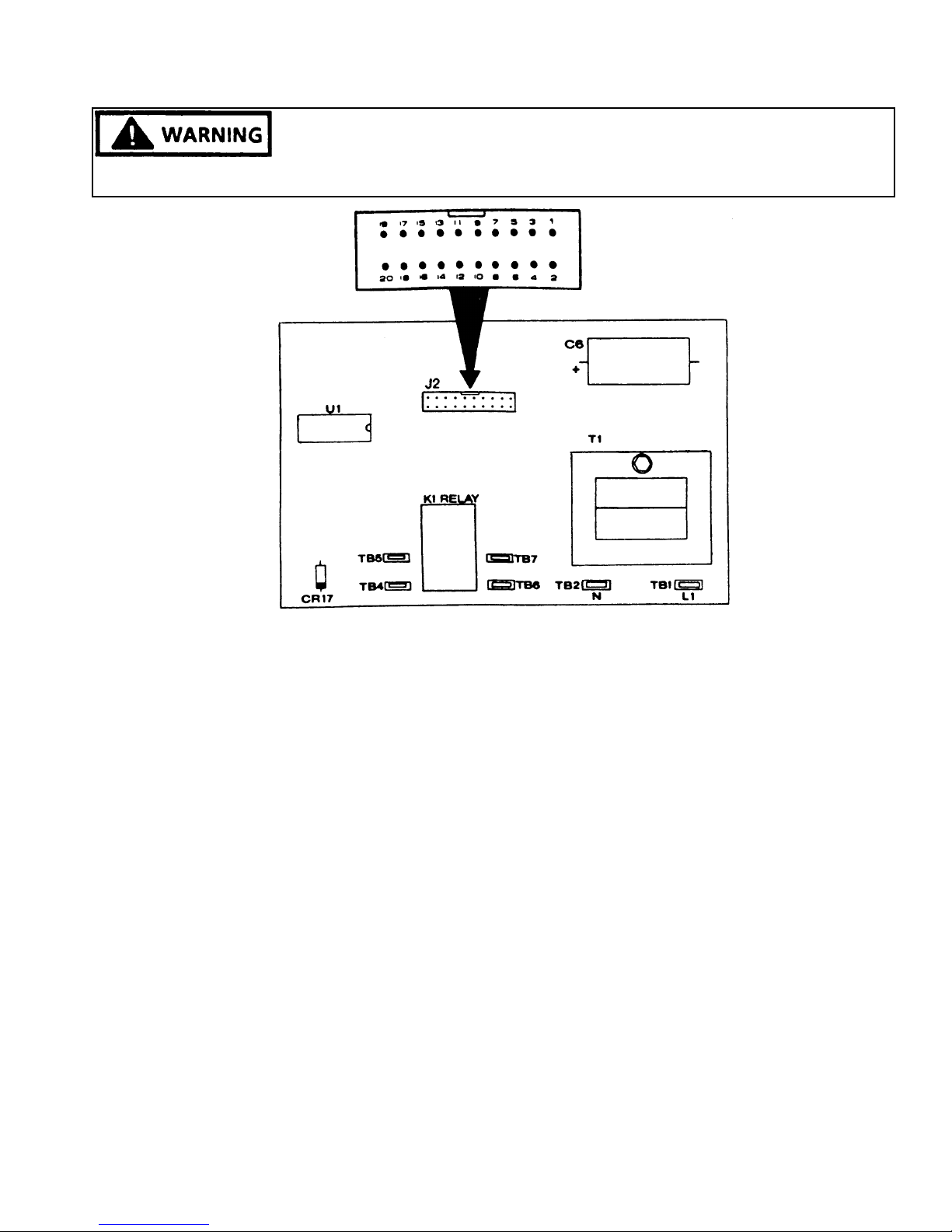
OPERATION AND SERVICE PROCEDURES
(SLIDE IN MODELS)
TO AVOID THE RISK OF ELECTRIC SHOCK, PERSONAL INJURY OR DEATH DISCONNECT POWER
BEFORE SERVICING, UNLESS TESTING REQUIRES IT.
Figure 57 - Clock/Timer P.C. Board
5. Set the Cook/Clean time for one (1) minute by pressing the "COOK/CLEAN TIME" button ("0:00" will be
displayed) and then pressing the "UP" button one
time ("0:01" should be displayed). After a short delay
the TB4 - TB5 contact should close (zero ohms),
"AUTO" and the oven indicator symbol should appear
on the left and center of the display, and the Time-ofDay will appear on the digital display. When the one
(1) minute Cook/Clean time elapses, the TB4 - TB5
contact should open (infinite ohms), an alarm will
sound for approximately ten (10) seconds and the
oven indicator symbol in the center of the display will
turn off. "AUTO" will continue to blink ON and OFF
to indicate that the Clock/Timer was programmed for
a timed operation. Press the "CANCEL/CLOCK"
button to turn off the blinking "AUTO" display.
6. Press the "STOP TIME" button and enter the stop
time for two (2) minutes past the time of day. EX-
AMPLE: Set the Time-of-Day to 12:00.
Press the "STOP TIME" button (the display will
continue to show the Time-of-Day), then press the
"UP" button until "12:02" is displayed.
After a short delay, contact TB4 - TB5 should close
(continuity) and the display will show the Time-of-Day
along with the oven indicator in the center of the
display and "AUTO" on the left of the display.
When the stop time is reached, the TB4 - TB5 contact
should open (infinite ohms), the oven indicator in the
center of the display turns off, and an alarm will sound
approximately ten (10) seconds. "AUTO" will continue to flash ON and OFF to designate that the Clock/
Timer was programmed for a timing function. Press
the "CANCEL/CLOCK" button to turn off the flashing
"AUTO" display.
7. Connnect the ohmmeter leads to terminals TB6 and
TB7 and repeat Steps 4 - 6 to test the other K1 relay
contact.
CLOCK P.C. BOARD VOLTAGE TESTS
Extreme caution must be taken when performing any live
voltage tests to avoid the possibility of electrical shock or
damage to the range components and/or testing equipment.
1. Shut off power to the range and disconnect the wire
leads from the P.C. board terminals L1 (TB1) and N
(TB2) to check the input voltage. Using a voltmeter
27 RC231002 Rev. 3
OPERATION AND SERVICE PROCEDURES
(SLIDE IN MODELS)
TO AVOID THE RISK OF ELECTRIC SHOCK, PERSONAL INJURY OR DEATH DISCONNECT POWER
BEFORE SERVICING, UNLESS TESTING REQUIRES IT.
set to read 120 VAC or higher, attach the meter leads
to the L1 and N wire leads and turn on power to the
range. A voltage reading of approximately 120 VAC
should be indicated. If no voltage is indicated, check
the range wiring. If 120 VAC is indicated shut off
power to the range and reconnect L1 and N wire leads
to the P.C. board terminals.
2. Disconnect the 20 pin ribbon cable connector from
the P.C. board J2 connector and turn on the power to
the range. Check for voltages at the following pins at
the J2 connector. (See Figure 28.)
PINS VOLTAGE
2-18 -25 to -35 VDC
6-18 -7 to -9 VDC
8-18 -7 to -9 VDC
10-18 -7 to -9 VDC
14-18 -25 to -35 VDC
15-18 -25 to -35 VDC
2-14 2.0 to 3.6 VDC
DISPLAY BOARD TESTING
Shut off power to the range and remove the display board
from the control panel (refer to Disassembly Procedures).
The function switches and diodes on the display board can
be checked at the J1 connector. Install the clock control
buttons into the display board switch housings. Refer to
Figure 30 for the correct pin number identification.
1. To check the "MINUTE TIMER" switch and CR3
diode, connect an ohmmeter (set to RX10 or higher)
to pins 8 and 17 at the display board J1 connector and
press the minute timer button. Reverse the ohmmeter leads and again press the "MINUTE TIMER"
button. On reading should indicate infinite ohms and
the other reading should indicate low ohms (the diode
conduction resistance and closed minute timer switch).
If a zero (0), low or infinite ohms reading is indicated
with the meter leads connected in both directions, the
display board should be replaced.
2. To check the "COOK/CLEAN TIME" switch and the
CR5 diode, connect the ohmmeter leads to pins 10
and 16 at the display board J1 connector and press
the "COOK/CLEAN TIME" button. Reverse the meter
leads and again press the "COOK/CLEAN TIME"
button. One reading should indicate infinite ohms
and the other reading should indicate low ohms (the
diode conduction resistance and closed "COOK/
RC231002 Rev. 3 28
CLEAN TIME" switch). If a zero, low, or infinite ohms
reading is indicated with the meter leads connected in
both directions, the display board should be replaced.
3. To check the "STOP TIME" switch and the CR5
diode, connect the ohmmeter leads to Pins 6 and 16
at the display board J1 connector and press the
"STOP TIME" button. Reverse the meter leads and
again press the "STOP TIME" button. One (1)
reading should indicate infinite ohms and the other
reading should indicate low ohms (the diode conduction resistance and closed STOP TIME switch). If a
zero (0), low or infinite ohms reading is indicated with
the meter leads connected in both directions, the
display board should be replaced.
4. To check the "UP" switch and the CR4 diode, connect
the ohmmeter leads to Pins 8 and 20 at the display
board J1 connector and press the "UP" button. Reverse the meter leads and again press the "UP"
button. One reading should indicate infinite ohms
and the other reading should indicate low ohms (the
diode conduction resistance and closed "UP" switch).
If a zero (0), low, or infinite ohms reading is indicated
with the meter leads connected in both directions, the
display board should be replaced.
5. To check the "DOWN" switch and the CR4 diode,
connect the ohmmeter leads to Pins 6 and 20 at the
display board J1 connector and press the "DOWN"
button. Reverse the meter leads and again press the
"DOWN" button. One reading should indicate infinite
ohms and the other reading should indicate low ohms
(the diode conduction resistance and closed "DOWN"
switch). If a zero (0), low, or infinite ohms reading is
indicated with the meter leads connected in both
directions, the display board should be replaced.
6. To check the "CLOCK/CANCEL" switch and the CR2
and CR4 diodes, connect the ohmmeter leads to Pins
10 and 20 at the display board J1 connector and press
the "CLOCK/CANCEL" button. Reverse the meter
leads and again press the "CLOCK/CANCEL" button.
One reading should indicate infinite ohms and the
other reading should indicate low ohms (CR2 and
CR4 diode conduction resistance and closed "CLOCK/
CANCEL" switch). If a zero (0), low, or infinite ohms
reading is indicated with meter leads connected in
both directions, the display board should be replaced.
7. The CR1 diode can be checked by connecting the

OPERATION AND SERVICE PROCEDURES
(SLIDE IN MODELS)
ohmmeter leads to Pins 10 and 17 at the display board
J1 connector and then reversing the ohmmeter leads.
One reading should indicate infinite ohms and the
other reading should indicate low ohms (CR1 diode
conduction resistance). If a zero (0), or infinite ohms
reading is indicated with the meter leads connected in
both directions, the display board should be replaced.
P.C. BOARD/DISPLAY BOARD
INTERCONNECT CABLE
The 20 pin ribbon cable that connects the Clock/Timer P.B.
board to the display board can be checked for continuity
using an ohmmeter set to the low ohms scale. Refer to
Figure 29 and 30 for correct pin identification. If an open
wire is indicated in the ribbon cable, the cable should be
replaced.
The information on Page 54 pertains to the 20 wire ribbon
cable which connects the P.C. board to the display board.
A switch was added to each wire of the ribbon cable to
demonstrate the results if that switch/wire opened. This
information may be useful in diagnosing and repairing
some display/control problems on the digital clock/timer.
Figure 58 - Display Board
Figure 59 - Display Board - Rear View
29 RC231002 Rev. 3
 Loading...