


PGA60C0902*
Amana PGA60C0902*, PGB24C0452, PGB24C0702, PGB24C0902, PGB30C0702 Service Instructions Manual
...
Service
Instructions
PHB**C, PHD**C PACKAGE HEAT PUMPS
PGA**C, PGB**C, PGD**C P ACKAGE GAS
& PCC**C P ACKAGE COOLERS
Models listed on
Page 6
®
to Goodman Company, L.P. All rights reserved. Copyright © 1999-2007 Goodman Company, L.P.
is a trademark of Maytag Corporation and is used under license
This manual is to be used by qualified, professionally trained HVAC
technicians only. Goodman does not assume any responsibility for
property damage or personal injury due to improper service
procedures or services performed by an unqualified person.
RS6300003 Rev. 1
January 2007

INDEX
IMPORT ANT INFORMA TION ........................................................................................................ 4
PRODUCT IDENTIFICATION ........................................................................................................ 6
ACCESSORIES............................................................................................................................. 9
LIGHTING INSTRUCTIONS ........................................................................................................ 13
PRODUCT DESIGN .................................................................................................................... 19
ELECTRICAL WIRING ................................................................................................................ 20
LINE VOL TAGE WIRING ............................................................................................................ .20
GAS SUPPLY AND PIPING......................................................................................................... 21
SYSTEM OPERATION ................................................................................................................24
SCHEDULED MAINTENANCE ................................................................................................... 30
SERVICING ................................................................................................................................. 31
S-1 CHECKING VOLTAGE..............................................................................................................35
S-2 CHECKING WIRING.................................................................................................................35
S-3 CHECKING THERMOSTAT, WIRING, AND ANTICIPATOR .................................................... 35
S-3A Thermostat and Wiring ............................................................................................................35
S-3B Cooling Anticipator...................................................................................................................35
S-4 CHECKING TRANSFORMER AND CONTROL CIRCUIT......................................................36
S-6 CHECKING TIME DELAY RELAY ............................................................................................ 37
S-7 CHECKING CONTACTOR AND/OR RELAYS ......................................................................... 37
S-8 CHECKING CONTACTOR CONTACTS..................................................................................37
S-9 CHECKING FAN RELAY CONTACTS ..................................................................................... 37
S-15 CHECKING CAPACITOR .........................................................................................................37
S-15A Resistance Check ....................................................................................................................38
S-15B Capacitance Check ..................................................................................................................38
S-16 CHECKING FAN AND BLOWER MOTOR............................................................................... 38
S-16B ECM/ICM Motors ......................................................................................................................39
S-16E Testing Interface Board ..........................................................................................................41
S-17 CHECKING COMPRESSOR WINDINGS ................................................................................45
S-17A Resistance Test .......................................................................................................................45
S-17B Ground Test..............................................................................................................................45
S-17D Operation Test .........................................................................................................................46
S-18 TESTING CRANKCASE HEATER ........................................................................................... 46
S-21 CHECKING REVERSING VALVE AND SOLENOID ................................................................47
S-22 REVERSING VALVE REPLACEMENT .....................................................................................47
S-24 TESTING DEFROST BOARD ..................................................................................................47
S-25 TESTING DEFROST CONTROL (30°/60°) .............................................................................49
S-50 CHECKING HEATER LIMIT CONTROL(S) ............................................................................49
S-52 CHECKING HEATER ELEMENTS ..........................................................................................49
S-53 OUTDOOR TEMPERATURE CONTROL ...............................................................................50
S-100 REFRIGERATION REPAIR PRACTICE ................................................................................... 50
S-101 LEAK TESTING ........................................................................................................................50
S-102 EVACUATION ............................................................................................................................50
S-103 CHARGING................................................................................................................................51
S-104 CHECKING COMPRESSOR EFFICIENCY .............................................................................52
S-105 THERMOSTATIC EXPANSION VALVE ....................................................................................52
2

INDEX
S-106 OVERFEEDING.........................................................................................................................52
S-107 UNDERFEEDING......................................................................................................................52
S-108 SUPERHEAT .............................................................................................................................53
S-109 CHECKING SUBCOOLING .....................................................................................................54
S-110 CHECKING EXPANSION VALVE OPERATION .......................................................................54
S-111 FIXED ORIFICE RESTRICTION DEVICES .............................................................................55
S-112 CHECKING RESTRICTED LIQUID LINE ................................................................................55
S-113 OVERCHARGE OF REFRIGERANT ........................................................................................55
S-114 NON-CONDENSABLES ...........................................................................................................55
S-115 COMPRESSOR BURNOUT ....................................................................................................55
S-200 CHECKING EXTERNAL STATIC PRESSURE ........................................................................56
S-301 TESTING AUXILIARY LIMIT.....................................................................................................57
S-302 CHECKING FLAME ROLLOUT SWITCH ................................................................................ 57
S-304 TESTING GAS VALVE...............................................................................................................58
S-306 CHECKING ORIFICES .............................................................................................................60
S-307 CHECKING GAS PRESSURE .................................................................................................. 60
S-308 CHECKING FOR DELAYED IGNITION ................................................................................... 61
S-309 CHECKING FOR FLASHBACK................................................................................................ 61
S-310 CHECKING PRESSURE CONTROL ......................................................................................61
S-311 HIGH ALTITUDE APPLICATION...............................................................................................66
S-313 TESTING IGNITION CONTROL MODULE ............................................................................66
S-314 CHECKING FLAME SENSOR .................................................................................................. 68
S-315 CHECKING HOT SURFACE IGNITER ....................................................................................70
WIRING DIAGRAMS.................................................................................................................... 71
3

IMPORTANT INFORMATION
Pride and workmanship go into every product to provide our customers with quality products. It is possible, however,
that during its lifetime a product may require service. Products should be serviced only by a qualified service technician
who is familiar with the safety procedures required in the repair and who is equipped with the proper tools, parts, testing
instruments and the appropriate service manual. REVIEW ALL SERVICE INFORMATION IN THE APPROPRIATE
SERVICE MANUAL BEFORE BEGINNING REPAIRS.
IMPORTANT NOTICES FOR CONSUMERS AND SERVICERS
RECOGNIZE SAFETY SYMBOLS, WORDS AND LABELS
WARNING
T
O PREVENT THE RISK OF PROPERTY DAMAGE, PERSONAL INJURY, OR DEATH,
DO NOT STORE COMBUSTIBLE MATE RIALS OR USE GASOLINE OR OTHER
FLAMMABLE LIQUIDS OR VAPORS IN THE VICINITY OF THIS APPLIANCE.
WARNING
G
OODMAN WILL NOT BE RESPONSIBLE FOR ANY INJURY OR PROPERTY DAMAGE ARISING FROM IMPROPER SERVICE OR SERVICE PROCEDURES.
I
F YOU INSTALL OR PERFORM SERVICE ON THIS UNIT, YOU ASSUME RESPONSIBILITY FOR ANY PERSONAL INJURY OR PROPERTY DAMAGE WHICH
MAY RESU LT.
M
ANY JURISDICTIONS REQU IRE A LICENSE TO INSTALL OR SERVICE HEATING AND AIR CONDITIONING EQUIPMEN T.
WARNING
HIGH VOLTAGE
ISCONNECT
D
INSTALLING THIS UNIT.
BE PRES ENT.
DAMAG E, PERS ONAL INJ URY OR DEATH.
POWER BEFORE SERVICING OR
ALL
MULTIPLE POWER SOURCES MAY
AILURE TO DO SO MAY CAUSE PROPERTY
F
To locate an authorized servicer, please consult your telephone book or the dealer
from whom you purchased this product. For further assistance, please contact:
CONSUMER INFORMATION LINE - AMANA® BRAND PRODUCTS TOLL FREE
1-877-254-4729 (U.S. only)
email us at: hac.consumer.affairs@amanahvac.com
fax us at: (931) 438- 4362
(Not a technical assistance line for dealers.)
(Not a technical assistance line for dealers.)
Your telephone company will bill you for the call.
4
Outside the U.S., call 1-931-433-6101.

IMPORTANT INFORMATION
SAFE REFRIGERANT HANDLING
While these items will not cover every conceivable situation, they should serve as a useful guide.
WARNING
REFRIGERANTS ARE HEAVIER THAN AIR. THEY CAN "PUSH OUT" THE
OXYGEN IN YOUR LUNGS OR IN ANY ENCLOSED SPACE.
POSSIBLE DI FFICULTY IN BREATHING OR DEATH:
•
EVER PURGE REFRIGERANT INTO AN ENCLOSED ROOM OR SPACE. BY
N
LAW, ALL REFRIGERANTS MUST BE RECLAI MED.
•
F AN INDOOR LEAK IS SUSPECTED, THOROUGHLY VENTILATE THE AREA
I
BEFORE BEGINNI NG WORK .
•
LIQUID REFRIGERANT CAN BE VERY COLD. TO AVOID POS SIBLE FROST-
BITE OR BLINDNESS, AVOID CONTACT WITH REFRIGERANT AND WEAR
GLOVES AND GOGGLES.
SKIN OR EYES, SEEK MEDI CAL HELP IMMEDIATELY.
A
•
LWAYS FOLLOW
AS POISONOUS GAS WILL BE PRODUCED.
I
F LIQUID REFRIGERANT DOES CONTAC T YOUR
EPA
REGULATIONS. NEVER BURN REFRIGERAN T,
TO AVOID
WARNING
TO AVOID POSSIBLE EXPLOSION:
EVER APPLY FLAME OR ST EAM TO A REFRIGERANT CY LINDER. IF YOU
•
N
MUST HEAT A CYLINDE R FOR FASTER CHARGING , PARTIALLY IMMERSE
IT IN WARM WATER.
NEVER FILL A CYLINDE R MORE THAN 80% FULL OF LIQ UID REFRIGERANT.
•
NEVER ADD ANYTHING OTHER THAN R-22 TO AN R-22 CYLINDER OR
•
R-410A TO AN R-410A CYLINDER . THE SERVICE EQUIPMENT USED MUST
BE LISTED OR CERTIF IED FOR THE TYPE OF REF RIGERANT USED.
TORE CYLINDERS IN A CO OL, DRY PLACE. NEVER USE A CYLIND ER
•
S
AS A PLATFORM OR A ROLLER.
WARNING
TO AVOID POSSIBLE EXPLOSION, USE ONLY RETURNABLE (NOT DISPOSABLE)
SERVICE CYLINDERS WHEN REMOVING REFRIGERANT FROM A SYSTEM.
ENSURE THE CYLINDER IS FREE OF DAMAGE WHICH COULD LEAD TO A
•
LEAK OR EX PLOS ION.
ENSURE THE HYDROST ATIC TEST DATE DOES NO T EXCEED 5 YEARS.
•
ENSURE THE PRESSURE RATING MEETS OR EXCEEDS 400 LBS.
•
WHEN IN DOUBT, DO NOT USE CYLINDER.
WARNING
WARNING
SYSTEM CONTAMINANTS, IMPROPER SERVICE PROCEDURE AND/OR PHYSICAL
ABUSE AFFECTING HERMETIC COMPRESSOR ELE CTRICAL TERMINALS MAY
CAUSE DANGEROUS SYSTEM VENTING.
The successful development of hermetically sealed refrigeration compressors has completely sealed the compressor's
moving parts and electric motor inside a common housing,
minimizing refrigerant leaks and the hazards sometimes associated with moving belts, pulleys or couplings.
Fundamental to the design of hermetic compressors is a
method whereby electrical current is transmitted to the compressor motor through terminal conductors which pass
through the compressor housing wall. These terminals are
sealed in a dielectric material which insulates them from the
housing and maintains the pressure tight integrity of the hermetic compressor. The terminals and their dielectric embedment are strongly constructed, but are vulnerable to careless compressor installation or maintenance procedures and
equally vulnerable to internal electrical short circuits caused
by excessive system contaminants.
T
O AVOID POSSIBLE INJURY, EXPLOSION OR DEATH, PRACTICE SAFE
HANDLING OF REFRIGERANTS.
In either of these instances, an electrical short between the
terminal and the compressor housing may result in the loss
of integrity between the terminal and its dielectric embedment. This loss may cause the terminals to be expelled,
thereby venting the vaporous and liquid contents of the compressor housing and system.
A venting compressor terminal normally presents no danger
to anyone, providing the terminal protective cover is properly
in place.
If, however, the terminal protective cover is not properly in
place, a venting terminal may discharge a combination of
(a ) hot lubricating oil and refrigerant
(b ) flammable mixture (if system is contaminated
with air)
in a stream of spray which may be dangerous to anyone in
the vicinity. Death or serious bodily injury could occur.
Under no circumstances is a hermetic compressor to be electrically energized and/or operated without having the terminal
protective cover properly in place.
See Service Section S-17 for proper servicing.
5

PRODUCT IDENTIFICATION
P G B 24 C 045 2 D
Product Type
Single Package
Cooling/Heating
Product Family
G - Gas/Electric
H - Heat Pump
C - Cooling
Product Series
A: 10 SEER Line
B: 11 SEER Line
C: 12 SEER Line
D: 13 SEER Line
Nominal Capacity
24: 24000 BTUH
30: 30000 BTUH
36: 36000 BTUH
42: 42000 BTUH
48: 48000 BTUH
60: 60000 BTUH
Engineering Revision
Voltage
2: 230V/60Hz/1ph
Heating Input
HEAT PUMPS
0: No heat installed
C: 10 kw heat installed
PACKAGE GAS
045: 45000 BTUH
070: 70000 BTUH
090: 90000 BTUH
115: 115000 BTUH
140: 140000 BTUH
Design Sequence
PGA60C0902*
PGA60C1152*
PGB24C0452*
PGB24C0702*
PGB24C0902*
PGB30C0702*
PGB30C0902*
PGB36C0702*
PGB36C0902*
PGB42C0902*
PGB42C1152*
PGB48C0902*
PGB48C1152*
PGB48C1402*
PGB60C0902*
PGB60C1152*
PGB60C1402*
PGD24C0452*
PGD24C0702*
PGD24C0902*
PGD30C0702*
PGD30C0902*
PGD36C0702*
PGD36C0902*
PGD42C0902*
PGD42C1152*
PGD48C0902*
PGD48C1152*
PGD48C1402*
PGD60C0902*
PGD60C1152*
PGD60C1402*
6
PHB24C02*
PHB30C02*
PHB36C02*
PHB42C02*
PHB48C02*
PHB60C02*
PHD24C02*
PHD30C02*
PHD36C02*
PHD42C02*
PHD48C02*
PHD60C02*
PHB24CC2*
PHB30CC2*
PHB36CC2*
PHD24CC2*
PHD30CC2*
PHD36CC2*
PCC24C02*
PCC30C02*
PCC36C02*
PCC42C02*
PCC48C02*
PCC60C02*

PRODUCT IDENTIFICATION
Package Gas Units
Model # Manufacturing # Description
ackage Gas (A) 10 Seer gas/elec tric units. New chass i s design with
PGA60C0902D
PGA60C1152D
PGA60C0902D
PGA60C1152D
PGA60C0902E
PGA60C1152E
PGA**C***2F
PGB**C***2D
P1217301C-P1217302C
P1220301C-1220302C
P1236201C-P1236202C
P1231901C-P1231902C
P1236309C-P1236313C
P1236408C-P1236411C
P1213601C-P1213608C
P1217201C-P1217207C
P
smaller footprint. PGA models have stronger blower perf ormance for down
shot applications .
P
ackage Gas (A) 10 Seer gas/e l ectric units. Changed from 26" fan blade to
22" fan blade to improve operating sound. PGA models have stronger blower
performance for down shot applications.
P
ackage Gas (A) 10 Seer gas/e l ectric units. Changed from Smart Valve
system to "DSI " direct spark ignition systems. PGA mode ls have stronger
blower performance for down shot applications.
P
ackage Gas (A) 10 Seer gas/el ectric units. Revised features include
alternate vendor for DSI ignition control, deletion of low voltage terminal
board (pigtail low voltage wire connections), alternate ID blower, and
alternate condenser fan/motor.
ackage Gas (B) 11 Seer gas/electri c uni ts. Ne w ch assis de si gn w ith
P
smaller footprint.
Gas Units
PGB**C***2D
PGB**C***2E
PGB**C***2E
PGD**C***2D P1204301C-P1204308C
PGD**C***2D
PGD**C***2E
PGD**C***2G
PGD**C***2G P1236522C-P1236529C
PGD**C***2X P1236530C-P1236533C
P1220201C-P1220207C
P1222201C-P1222208C
P1231701C-P1231708C
P1231801C-P1231807C
P1236401C-P1236407C
P1236301C-P1236308C
P1222301C-P1222308C
P1231402C-P1231407C
P1232001C-P1232008C
P1232101C-P1232107C
P1236501C-P1236513C
P1236514C-P1236521C
P1236608C-P1236613C
P
ackage Gas (B) 11 Seer gas/electric units. Changed from 26" fan blade to
22" fan blade to improv e operating sound.
P
ackage Gas (B) 11 Seer gas/electric units. Changed from Smart Valve
system to "DSI" direct spark ignition systems.
P
ackage Gas (B) 11 Seer gas/electric units. Upgraded with burner bracket
used on 90% gas furnaces.
P
ackage Gas (D) 13 Seer gas/electric units. New chassi s desi gn w i th
smaller footprint.
P
ackage Gas (D) 13 Seer gas/electric units. Changed from 26" fan blade to
22" fan blade to improv e operating sound.
P
ackage Gas (D) 13 Seer gas/electric units. Changed from Smart Valve
system to "DSI" direct spark ignition systems.
P
ackage Gas (D) 13 Seer gas/electr ic units. Changed from tan to new
architectrual gray/executive gray color.
P
ackage Gas (D) 13 Seer gas/electric units. Changed from TXV to Flowrator
on 2 - 3 1/2 ton models.
P
ackage Gas (D) 13 Seer gas/electric units. Introduce TXV equipped PGD
"2X" models 2 - 3 1/2 ton.
7

PRODUCT IDENTIFICATION
Model # Manufacturing # Description
ackage Heat Pump (B) 11 Seer heat pump units. New chassis design with smaller
PHB**C02D P1214402C-P1214404C
PHB**C02E P1204501C-P1214404C
PHB**C02E P1220101C-P1220106C
PHB**CC2E P1228101C-P1228103C
PHB**CC2E P1235801C-P1235803C
PHB**C02E P1235601C-P1235606C
PHB**C02E1 P1239207C-P1239212C
PHB**CC2E1 P1239904C-P1239906C
PHB**C02E1 P1239214C-P1239219C
P
footprint.
P
ackage Heat Pump (B) 11 Seer heat pump units. New chassis design with smaller
footprint. Improved heating capacity
P
ackage Heat Pump (B) 11 Seer heat pump units. Changed from 26" fan blade to
22" fan blade to improve operating sound.
P
ackage Heat Pump (B) 11 Seer heat pump units. New chassis design with smaller
footprint. With 10 K.W. factory installed heat strips.
P
ackage Heat Pump (B) 11 Seer heat pump units. Changed to Ranco Defrost
Board. Moved low pressure switch to suction side.
P
ackage Heat Pump (B) 11 Seer heat pump units. Changed to Ranco Defrost
Board. Moved low pressure switch to suction side.
P
ackage Heat Pump (B) 11 Seer heat pump units. Tubing redesigned to improve
serviceability and reduce the potential for distributor tubes rubbing and leaking.
P
ackage Heat Pump (B) 11 Seer heat pump units. Tubing redesigned to improve
serviceability and reduce the potential for distributor tubes rubbing and leaking.
P
ackage Heat Pump (B) 11 Seer heat pump units. Change to UTEC Defrost Board.
Moved low pressure switch to liquid line and changed pressure setting from 5 PSIG
to 15 PSIG. Moved ECM interface board to return air section.
Heat Pumps and Coolers
PHB**CC2E1
PHB**C02F1 P1239220C-P1239225C
HEA T PUMPS
PHB**CC2F1 P1239911C-P1239913C
PHD**C02E P1224301C-P1224305C
PHD**C02E P1235701C-P1235705C
PHD**CC2E P1228201C-P1228203C
PHD**CC2E P1235901C-P1235903C
PHD**C02E1 P1239706C-P1239710C
PHD**CC2E1 P1240004C-P1240006C
PHD**C02E1 P1239711C P
PHD**CC2E1 P1240007C
PHD**C02F1 P1239718C-P1239723C
PHD**CC2F1 P1240011C-P1240013C
P1239908C-P1239910C
P1240008C-P1240010C
P
ackage Heat Pump (B) 11 Seer heat pump units. Change to UTEC Defrost Board.
Moved low pressure switch to liquid line and changed pressure setting from 5 PSIG
to 15 PSIG. Moved ECM interface board to return air section.
P
ackage Heat Pump (B) 11 Seer heat pump units. Changed from tan to new
corporate colors.
P
ackage Heat Pump (B) 11 Seer heat pump units. Changed from tan to new
corporate colors.
P
ackage Heat Pump (D) 13 Seer heat pump units. New chassis design with smaller
footprint.
P
ackage Heat Pump (D) 13 Seer heat pump units. Changed to Ranco Defrost
Board. Moved low pressure switch to suction side.
P
ackage Heat Pump (D) 13 Seer heat pump units. New chassis design with smaller
footprint. With 10 K.W. factory installed heat strips.
P
ackage Heat Pump (D) 13 Seer heat pump units. Changed to Ranco Defrost
Board. Moved low pressure switch to suction side.
P
ackage Heat Pump (D) 13 Seer heat pump units. Tubing redesigned to improve
serviceability and reduce the potential for distributor tubes rubbing and leaking.
P
ackage Heat Pump (D) 13 Seer heat pump units. Tubing redesigned to improve
serviceability and reduce the potential for distributor tubes rubbing and leaking.
ackage Heat Pump (D) 13 Seer heat pump units. Scroll compressor.
ackage Heat Pump (D) 13 Seer heat pump units. Scroll compressor.
P
P
ackage Heat Pump (D) 13 Seer heat pump units. Changed from tan to new
corporate colors.
P
ackage Heat Pump (D) 13 Seer heat pump units. Changed from tan to new
corporate colors.
Model # Manufacturing # Description
PCC**C02E P1231101C-P1231106C
PCC**C02F P1231107-P1231112C
PCA**C02E P1234801C-P1234806C
COOLERS
PCA**C02F P1234807C-P1234811C
8
P
ackage Cooling (C) 12 Seer electric heat electric cooling units. New chassis design
with smaller footprint.
P
ackage Cooling (C) 12 Seer electric heat electric cooling units. Changed from tan
to new corporate colors.
P
ackage Cooling (A) 10 Seer electric heat electric cooling units. Changed from tan
to new corporate colors.
ackage Cooling (A) 10 Seer electric heat electric cooling units. New condenser
P
fan/motor.

ACCESSORIES
Additional Amana® brand accessories, as described below, can be purchased to fit specific application needs. Accessories
can be ordered by the following part numbers and each accessory includes its own separate instructions.
ACCESSORY PART NUMBER DESCRIPTION
Duct Transition Round RSDK01A (24-60)
Converts existing round duct connections to rectangular. Used to install
the ho rizont al duct cover kit on
heat pump units
.
Duct Transition
Over/Under
Roof Curbs
Horizontal Du ct Co ver
Kits
50°F Compressor
Lockout
Ambient Thermostat Kit ATK01
Compressor Sound
Blankets
Propane Gas Conversion
Kit
Electric He ater Kits
Single Point Wiring Kits
PDTR0U4A (Sm Chassis)
PDTR0U6A (LG Chassis)
PRC06A1
PRC07A1
PRC08A1
CHK001A
CHK002A
CHK601A (6 PACK)
LOK501A
CSB04A
CSB07A
CSB08A
CSB09A
LPTK07A
LPTK09
PHCB05C1
PHCB10C1
PHCB15C1
PHCB20C1
SPK04A
SPK05A
SPK06A
SPK07A
SPK08A
SPK09A
Converts existing side by side duct connections to over & under
ductwork. (F o r replacemen t p u r poses). Some Amana preceding unit s
had over & under ductwork. For use on
Roof top mounting/support system for package units. Must be used when
unit is installed in downflow applications. PRC06A fits
pump and coolers
is a combo roof curb adaptable to either footprint.
Block s off horizontal dis c h arge. Used for downflow ap p l ications. For use
on
all Amana® brand Packa ge Units.
Prevents mechanical cooling at ambients below 50°F. For use on
Amana® brand Package Units.
This kit controls the staging of electric heat and allows supplemental
heat to be energized only when a set outdoor temperature is reached.
This will allow the system's heat output to more closely match the
building's load. For use on
Compressor sound blankets reduce the ambient noise level of the
package units. Used in installations where extra quite operation is
desired. For use on
Converts
4.8KW 1ph - 30 Amp Circuit Breaker
9.6KW 1ph - 50 Amp Circuit Breaker
14.4KW 1ph - 30 & 50 Amp Circuit Breakers
19.2KW 1ph - 2-50 Amp Circuit Breakers
For use on
Single point wiring kit allows one electrical supply connection to power
both heater kit and package unit. For use on
package units
packa ge gas units
heat pum p and cooling package units
. PRC07A1 fits Package gas/electric units. PRC08A1
.
.
heat pump and cooling package units
all Amana® brand Package Units.
from natural gas to propane gas operation
.
all Amana
®
brand Package Units.
Package heat
all
.
.
.
heat pu m p and cool ing
9

ACCESSORIES
Accessories
PHCB**C1
SPK**A
PRC06A1
PRC07A1
PRC07A1
PDTROU4A
PDTROU6A
P1219401C-P1219406C
P1219408C-P1219412C
P1221701C-P1221706C
P1221708C-P1221712C
P1219801C-P1219803C
P9850603C-P9850604C
ackage Heat kit with Circuit Breakers. Electric heat kits include breakers
P
for electric heat only.
ingle Point power connection Kit. Kit allows for one circuit to provide
S
power supply for package heat pumps (PHB/PHD**C) and coolers
(PCC**C). Kit includes circuit breaker for compressor.
ackage Roof Curb Kit. Accessory roof curb for roof top/down discharge
P
installations. PRC06A1 is designed for package heat pumps and coolers.
PRC07A1 is designed for package gas units. PRC07A1 is a combo curb
and will adapt to either footprint.
ackage Duct TRansition Over-Under kit. Transition converts side by side
P
to over-under duct connections. Early model Amana units (EPCG, EPHO,
EP, and PHK) had over-under duct connections.
THERMOSTATS
THSMEC1H2BA Manual changeover - 2 Stage Heat
THSADC1H2BA Auto changeover - 2 Stage Hea t
THSMDC1H2BA Manual changeover - 2 Stage Heat
THSMDC1H3BA Auto changeover - 3 Stage Hea t
1213401 Electronic programmable - 1 Stage Heat, 1 Stage Cool
1213403 Electronic non-programmable - 2 Stage Heat, 1 Stage Cool
1213404 Electronic non-programmable - 2 Stage Heat, 1 Stage Cool
1213405 Electronic programmable - 2 Stage Heat, 1 Stage Cool
1213701 Electronic programmable - 1 Stage Heat, 1 Stage Cool
1214901 Electronic programmable - 2 Stage Heat, 2 Stage Cool
C5200607 Manual changeover - 1 Stage Heat, 1 Stage Cool
M0380101 Manual changeover - 1 Stage Heat, 1 Stage Cool
D6853512 Auto changeover - 1 Stage Heat, 1 Stage Cool
D6853510 Auto changeover - 2 Stage Heat, 1 Stage Cool
D9945801 Manual changeover - 2 Stage Heat, 1 Stage Cool
D9807604 Electronic programmable - 1 Stage Heat, 1 Stage Cool
1213402 Manual Changeover - Nonprogrammable Digital - 1 Stage Heat, 1 Stage Cool
1213406 Manual/Auto Changeover - 5 + 2 Programming Digital - 3 Stage Heat, 2 Stage Cool
1213407 Manual Changeover - 5 + 2 Programming Digital - 2 Stage Heat, 2 Stage Cool
1213408 Manual/Auto Changeover -7 Day Programming Digital - 1 Stage Heat, 1 Stage Cool
1213410 Manual Changeover - 5 + 2 Programming Digital - 2 Stage Heat, 1 Stage Cool
1213411 Manual Changeover - Nonprogrammable Digital - 2 Stage Heat, 2 Stage Cool
1213412 Manual/Auto Changeover - 7 Day Programming Digital - 3 Stage Heat, 2 Stage Cool
1213431 Manual/Auto Changeover - 7 Day Programming Digital - 3 Stage Heat, 2 Stage Cool
10
ACCESSORIES
5
3
1
"
42
-
3/8
"
"
19
SUPPLY
-
3/
1
6"
1
9
-3
/
1
6"
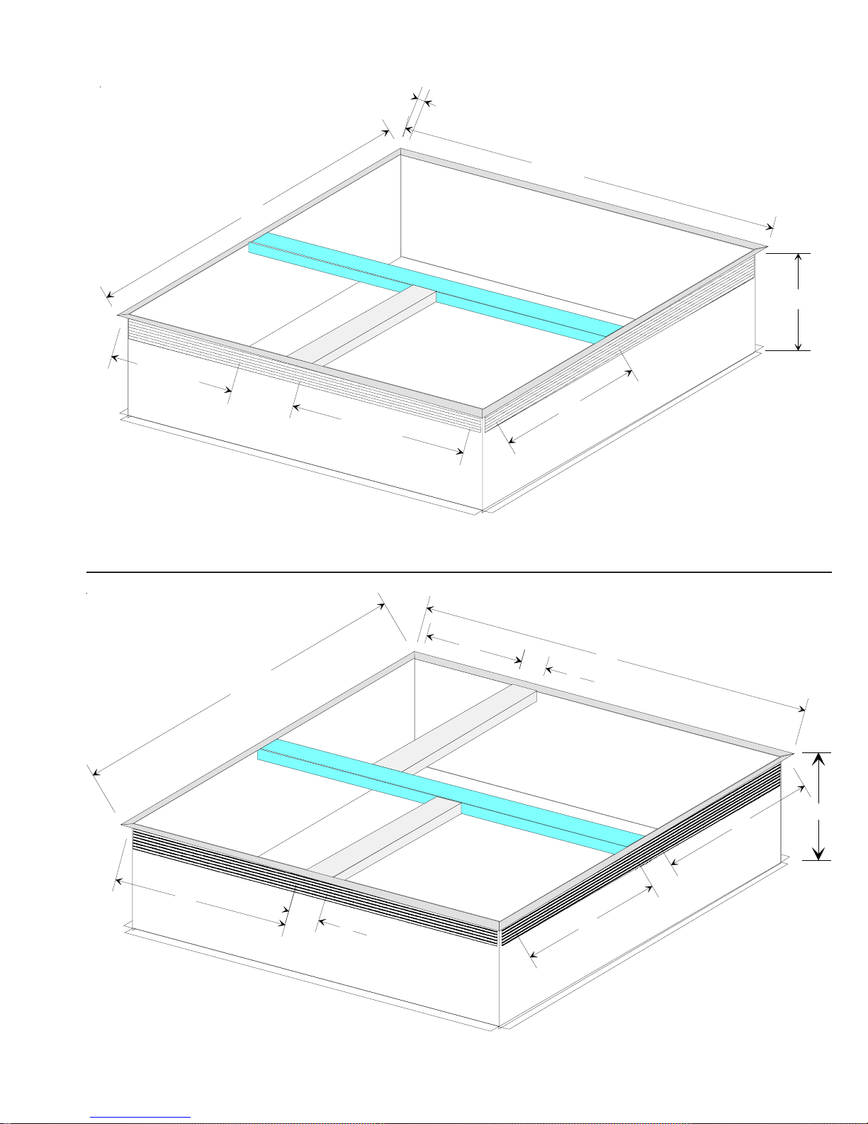
PRC06A1 ROOF CURB
"
8
/
3
-
2
4
SUPPLY
RETURN
1
2
"
"
9
1
4
7
"
2
"
14"
RETURN
2
5
"
"
5
2
"
2
"
PRC07A1 ROOF CURB
2
1
14"
11

ACCESSORIES
A
®
A
1
12
UNIT SUPPORT
47
14
42 3/8
24 3/8
2
RETURN
SUPPLY
14
14
35
INSULATED PLATFORM
PRC08A ROOF CURB
J
H
B
D
A
G
F
E
1.00"
C
OVER/UNDER DUCT TRANSITION
AMAN
BRAND
MODEL
"A" DIM "B" DIM "C" DIM "D" DIM "E" DIM "F" DIM "G" DIM "H" DIM "J" DIM
PDTROU4A 42" 26 7/16" 12" 26 1/4" 15" 6 7/8" 20 11/16" 9/16" 9/16"
PDTROU6
42" 32" 12" 39 1/2" 15" 10" 20 11/16" 1" 9/16"
Duct Transition
Over/Under
PDTROU4A
PDTROU6A
12
Converts existing side by side duct connections to over/under ductwork.
(For replacement purposes. The Amana® brand's preceding units had
over/under ducts.)

LIGHTING INSTRUCTIONS
F
O
Y
O
R
R
E
B
A
E
D
F
If you do not follow these instructions
WARNING
exactly, a fire or explosion may result causing property
damage, personal injury or loss of life.
is
T
h
A
.
w
ic
h
lig
o
t
B
.
B
E
F
a
a
e
r
c
e
b
t
t
e
s
H
A
T
W
D
D
D
m
I
h
p
f
I
a
c
C
U
.
n
o
e
s
N
e
v
e
r
,
d
n
a
h
ic
n
h
c
e
t
p
x
e
r
o
D
D
.
n
o
o
m
I
m
d
e
a
e
h
t
p
ys
m
s
e
t
li
p
p
a
n
a
o
t
u
a
h
e
h
t
t
h
O
R
E
a
g
r
o
f
so
e
s
u
a
o
le
h
t
n
D
T
O
O
tr
t
o
n
o
to
t
o
n
o
s
u
t
o
n
o
m
ia
d
e
.
e
n
o
F
a
c
u
o
y
ir
ll
f
th
e
r
u
o
y
ly
o
o
t
e
s
u
n
o
d
y
r
'
t
t
ia
F
.
n
o
lo
io
s
.
n
th
e
s
u
t
ia
te
c
ly
lia
p
e
c
n
a
a
d
n
ip
u
q
e
p
is
e
c
m
a
lig
ic
lly
a
t
y
b
ilo
p
t
h
d
n
a
O
P
E
R
N
A
T
I
o
t
e
r
u
B
s
.
e
s
is
s
h
a
g
m
e
.
lo
r
o
f
e
Y
O
S
U
F
I
lig
o
t
h
y
a
n
t
le
e
y
n
a
h
c
u
e
e
t
ll
o
n
e
h
ls
to
c
r
is
a
a
y
n
n
o
h
p
y
n
a
ll
a
c
u
o
y
ly
a
g
e
h
t
w
o
h
c
a
e
r
t
o
n
p
e
d
m
e
t
r
a
p
o
t
d
n
a
u
o
n
k
e
h
t
f
I
.
,
it
ir
a
p
e
r
te
m
t
a
r
o
e
p
p
a
lia
e
c
n
ll
lif
a
u
q
i
a
e
la
p
e
r
o
t
d
n
r
t
n
o
c
s
a
g
S
U
A
R
F
E
T
O
O
R
E
a
w
h
it
d
e
n
ilo
p
e
h
t
s
t
h
.
m
s
ll
e
a
G
m
s
ll
e
x
e
n
v
a
e
n
a
h
t
ie
r
G
M
A
E
L
L
lia
p
p
a
c
n
y
ic
s
r
h
w
c
it
t
c
e
r
u
o
y
in
s
a
g
r
lie
p
p
s
lie
p
p
u
s
s
's
r
s
s
a
g
r
u
o
y
.
t
n
n
in
r
u
h
s
t
r
o
b
w
ill n
p
t
o
ll
a
c
a
lif
a
u
q
a
p
e
r
d
e
t
p
ir
r
a
p
y
n
a
if
t
ic
v
e
s
d
r
e
e
c
r
a
p
y
n
a
w
l
ic
o
h
a
h
h
Y
P
E
N
R
A
T
I
G
ic
v
e
e
d
ig
io
it
n
n
.
t
t
o
n
D
o
y
r
t
p
p
a
e
h
ll a
t
d
n
u
o
r
lo
r
o
f
e
h
t
o
t
t
w
a
ill
ir
a
d
n
S
.
e
;
ild
u
b
in
.
g
i
e
n
a
m
fr
o
r
r
in
t
s
p
lie
p
r
g
e
h
t
in
h
s
u
ie
s
d
m
y
a
b
s
a
h
t
ic
n
h
c
e
h
t
f
o
t
e
e
b
s
b
h
g
io
.
s
n
t
c
u
,
c
s
a
l
tr
o
n
o
n
r
u
t
r
o
y
b
ic
v
e
r
e
lt
u
a
s
e
in
r
r
e
d
n
u
n
e
e
o
t
ia
n
in
p
s
tr
o
n
o
c
e
l
w
u
n
a
r
e
d
n
A
R
V
E
I
L
A
M
E
N
AVERTISSEMENT:
N
M
D
E
E
T
A
R
T
T
R
E
C
H
R
E
E
I
L
Ouiconque ne respcte pas `a
la lettre les instructions dans le present manuel risque
de declencher un incendie ou une explosion entrainant
des dommages materiels, des lesions corporelles ou la
perte de vies humaines.
m
il
e
t
s
e
r
a
p
p
a
C
t
e
A
.
i a
u
q
llu
li
e
c
n
a
's
r
o
.
b
o
n
k
e
ir
f
.
r
e
w
t
a
t
c
e
e
t
.
r
e
t
t
n
A
B
.
n
e
r
e
n
u
r
e
c
u
e
p
Q
U
C
N
.
e
q
u
S
i
p
e
r
t
n
e
d
e
N
e
D
.
d
a
c
e
t
m
e
r
to
u
to
u
a
m
m
e
'a
d
llu
d
N
m
e
d
n
a
l'e
la
c
la
m
r
e
D
N
E
T
t
u
o
t
r
n
N
A
S
u
u
o
a
t
u
e
d
r
u
e
a
g
s
z
a
g
n
o
s
s
m
'a
c
t
c
u
R
E
F
A
I
e
n
e
t
s
a
p
u
o
t
e
r
e
h
c
ilis
'u
n
t
r
e
u
a
le
e
p
p
im
r
m
e
lo
p
n
e
y
r
e
t
c
e
R
p
s
e
is
u
n
e
s
r
u
o
f
p
i
n
n
o
s
r
e
in
d
n
e
c
ie
.
s
r
e
s
s
o
t
u
o
m
ne
in
a
;
s
e
r
e
tt
e
n
a
le
e
p
p
a
r
;
r
la
r
e
c
r
o
f
e
e
e
n
u
r
e
h
c
v
r
e
s
e
s
s
u
a
m
o
c
,
u
ic
q
ie
n
a
t
u
o
t
r
e
c
m
o
m
d
n
a
r
e
V
A
le
if
o
in
a
t
e
v
E
p
o
la
'a
la
r
a
e
t
c
le
p
s
n
n
h
p
e
t
d
'u
d
i
n
u
n
iq
t
a
m
e
t
n
e
ille
e
v
s
m
e
R
F
A
I
E
L
l'a
a
e
d
p
p
r
R
le
.
if
z
n
e
r
t
d
lo
r
u
lu
p
s
le
r
iv
n
a
e
a
Y
L
S
'I
A
'a
d
llu
te
r
m
e
in
t
n
u
c
u
a
le
e
t
n
u
h
p
c
m
e
m
e
ia
d
e
t
le
t
n
a
le
e
t
p
a
r
t
le
la
t
e
.
z
a
g
d
e
r
n
o
p
e
r
n
e
e
m
la
r
e
n
r
u
ja
m
m
e
is
a
t
in
o
e
e
c
c
e
n
u
ic
n
h
c
e
t
m
t
e
n
a
o
e
t
lo
p
x
io
s
n
o
c
e
d
t
e
ir
m
e
le
p
n
e
t
in
r
u
o
lif
p
ie
a
p
u
d
ie
t
r
u
q
e
i o
t
n
'a
d
ll
if
is
it
s
o
p
e
v
la
u
n
a
E
ie
l
r
s
e
r
p
u
q
s
d
u
u
U
N
l'a
r
u
r
r
e
e
n
o
le
t
n
n
o
h
le
s
a
,
d
e
n
a
lo
p
e
e
n
,
ie
q
n
d
u
u
u
p
a
p
o
t
p
s
s
y
s
e
t
e
m
u
e
g
a
N
ille
e
.
e
s
u
lle
e
m
F
O
N
o
p
r
u
u
d
l'a
e
l.
o
s
O
E
p
a
p
u
e
t
p
r
n
a
d
u
o
f
u
d
e
u
r
in
t
s
p
le
e
p
d
e
t
t
'o
d
r
s
a
p
lif
a
ie
r
la
e
in
c
n
il
e
r
a
e
u
n
e
t
c
e
m
e
t
lo
p
s
a
p
.
t
n
e
O
C
N
T
I
N
E
R
le
e
c
e
d
l
p
e
h
c
n
a
t
e
ir
D
E
U
ie
l.
r
iq
r
le
e
t
c
s
a
b
le
is
n
e
s
r
u
is
o
v
in
n
io
s
n
t
c
er
s
le
r
'a
m
d
is
s
i
t
u
e
c
a
l
e
t
n
e
t
r
Q
.
ic
u
r
e
r
a
p
e
ie
d
n
e
.
e
'il
s
a
tie
r
a
p
r
l'a
p
p
c
e
d
e
o
d
s
e
g
n
,
r
ca
,
r
r
R
G
D
A
E
Z
;
e
u
im
t
t.
n
e
z
a
g
e
d
r
.
u
d
s
e
d
ic
v
e
z
a
g
u
d
io
n
.
t
e
f
f
e
t
la
e
d
o
e
u
q
n
u
e
p
t
lo
p
g
n
e
t
e
A
l
e
p
p
n
.
a
a
u
r
e
il
e
t
e
r
t
n
t
e
le
o
r
s
n
l
'e
.
u
a
O
P
E
R
A
.
1
S
T
O
P
R
.
d
a
S
.
2
T
.
3
T
.
4
e
d
D
o
T
.
5
"
O
W
.
6
m
s
e
h
t
in
y
if
e
n
T
.
7
u
o
c
R
.
8
T
.
9
o
p
S
.
0
1
1
1
I
.
fo
O
s
.
1
S
T
.
2
if
T
.
3
"
4
R
.
e
la
l.
e
is
b
h
t
e
u
h
u
o
f
e
u
w
f
ll
ff
e
s
O
m
s
o
r
e
h
t
e
h
t
t
n
o
r
ll
a
f
le
e
t
c
f
li
p
p
a
is
ic
v
e
n
o
t
n
r
F
F
a
f
it
ll
e
f
m
s
n
m
r
d
u
o
s
t
x
g
n
r
n
u
e
t
la
p
o
n
r
r
e
t
t
e
e
h
t
w
o
G
a
ic
v
r
T
h
t
t
e
r
u
n
v
r
e
n
r
u
F
la
p
e
is
e
c
n
a
w
ic
h
h
t
u
a
t
lig
o
h
t
y
r
t
o
c
s
a
g
e
h
io
it
.
s
n
o
p
"
m
in
)
5
(
iv
e
o
in
,
s
a
g
c
r
ll
e
,
s
a
g
S
b
a
io
n
t
a
v
o
m
s
ll
e
't
n
o
.
p
e
t
l
o
r
t
n
o
c
s
a
lo
w
c
k
is
c
e
r
e
c
s
s
e
c
c
a
ll
a
n
le
e
t
c
p
p
a
e
h
t
o
t
t
a
m
t
s
o
r
e
h
lia
p
p
a
e
c
n
t
c
r
in
t
s
e
h
t
s
A
lia
p
p
T
o
e
t
e
ch
ic
n
ia
T
U
O
R
N
m
o
r
e
h
t
e
ll
a
f
le
e
f
o
ic
o
t
is
e
g
e
h
t
c
s
a
io
it
s
o
p
F
"
r
c
e
c
t
n
o
N
S
T
N
G
T
I
f
a
s
e
h
t
lo
o
t
t
a
t
ic
p
r
w
o
ip
u
q
e
ic
m
o
t
a
p
e
h
t
t
o
r
t
n
n
k
l
D
o
o
n
t
o
t
s
e
lu
in
d
g
T
O
P
.
h
n
o
t
e
g
,
s
a
g
b
o
n
k
o
t
l.
e
n
a
p
ic
l
a
r
lia
e
c
n
d
o
t
s
e
w
ill
n
T
"
io
s
n
"
e
c
n
g
r
o
n
O
F
t
ta
s
t
tr
ic
c
a
e
p
e
b
o
r
t
n
o
D
.
n
o
c
a
l
o
c
R
I
U
in
y
t
e
w
s
e
o
t
r
e
d
e
p
lly
a
lig
ilo
b
t
c
b
o
c
r
o
f
t
le
c
r
a
r
a
e
n
llo
F
o
la
is
o
t
o
O
N
"
.
s
d
e
ir
o
p
o
t
T
o
u
d
n
a
o
c
s
a
G
F
lo
o
w
w
o
p
l
m
r
o
f
r
o
n
k
l
t
o
n
s
s
e
C
O
N
T
I
S
.
1
A
R
R
E
T
f
io
m
t
r
a
o
in
.
g
t
t
e
s
t
lia
p
p
a
e
h
t
w
ith
a
ig
n
e
h
t
s
t
h
.
d
n
a
h
y
lo
w
k
is
c
e
.
e
g
y
n
a
o
t
h
t
lo
f
e
r
o
w
in
B
"
"
l.
e
b
.
"
in
.
g
t
t
e
,
e
t
a
r
e
n
r
a
c
ll
r
u
o
y
m
n
a
p
.
y
T
O
A
S
t
t
e
s
t
s
e
h
t
o
t
r
e
.
d
e
lo
c
c
b
w
k
f
.
e
c
r
o
l.
e
n
a
p
n
o
e
v
o
b
a
n
.
e
c
n
io
it
n
n
ilo
p
.
t
o
t
n
e
T
h
.
s
a
u
o
y
f
I
.
y
t
e
f
a
s
e
h
t
R
O
M
A
"
ON
A
P
P
in
e
is
A
I
L
.
g
lia
p
p
a
e
c
n
o
t
e
G
A
A
N
E
T
B
I
P
E
O
N
N
U
E
,
L
O
M
N
A
/
R
C
H
E
OFF
M
K
I
N
C
N
I
A
R
R
D
U
A
N
G
U
A
L
N
O
B
S
H
O
P
O
N
"
"
N
O
E
la
.
2
R
C
o
.
3
C
e
.
4
llu
a
'a
d
T
o
.
5
'u
d
N
A
t
.
6
a
g
la
p
A
Z
S
"
G
A
S
E
L
T
V
E
E
I
G
A
Z
A
S
N
W
S
u
s
S
T
o
.
7
ig
a
R
e
.
8
M
.
9
R
.
0
1
1
S
.
1
i
in
e
d
u
q
.
1
R
e
C
.
2
fa
T
o
.
3
'u
d
N
.
4
R
e
E
p
u
s
io
n
t
r
o
p
r
e
h
t
le
le
g
e
r
u
l'a
r
e
p
lim
e
p
a
t
il e
e
r
a
p
t
u
a
m
e
m
o
v
llu
la
m
r
e
in
b
o
r
le
r
e
n
r
e
e
t
z
R
r
'il
u
e
e
l'a
s
a
e
r
m
t
n
o
e
n
e
c
fo
r
s
a
p
in
c
q
e
r
d
n
R
e
.
ifle
n
r
o
p
,
r
e
h
c
n
u
R
E
T
E
R
.
!
io
n
t
r
o
p
la
as
p
a
'y
n
b
o
r
le
r
e
n
r
ille
u
'u
d
n
s
e
r
t
m
t
e
p
n
e
l'a
e
p
p
r
t
t
a
r
e
h
t
le
le
g
r
il
e
n
r
a
p
p
in
io
s
n
t
u
c
r
t
a
g
l'a
e
d
p
z
lifie
o
le
u
P
O
U
e
h
t
le
le
g
r
o
l'a
lim
r
e
p
u
r
p
t
u
e
m
e
d
e
c
o
r
e
n
r
u
r
le
m
e
n
tr
n
o
e
c
fo
r
s
a
p
e
e
n
r
tt
e
E
S
M
E
I
L
.
R
!
le
u
r
e
m
ta
s
o
tio
a
t
n
m
u
t
s
iq
e
u
t
a
ille
e
u
t
e
a
.
r
m
)
5
(
a
t
u
o
t
c
e
d
r
s
P
s
a
e
p
u
s
'o
d
e
d
a
in
t
e
m
n
o
e
la
e
c
il
e
o
s
r
m
o
a
t
s
m
e
s
e
le
u
it
t
il
e
r
a
p
n
r
u
o
f
C
R
G
D
E
m
s
o
r
a
t
n
e
d
a
r
in
b
o
e
e
.
r
la
p
c
e
M
N
A
R
C
H
E
io
n
t
u
c
r
in
t
s
le
s
is
z
e
r
d
e
a
t
e
n
d
i
n
m
e
m
e
s
z
a
g
e
in
t
u
u
o
t
u
le
e
r
r
e
a
r
ie
u
d
r
u
a
g
e
r
t
p
le
s
u
t
a
t
e
s
e
t
e
is
e
s
O
A
a
t
t
tio
s
e
a
t
n
e
le
iq
u
t
e
e
et
c
t
e
t
a
m
e
r
e
p
t
la
le
t
c
e
d
iq
e
u
r
is
d
'u
n
it
s
o
p
t
n
ille
e
v
la
u
lle
e
u
n
a
m
e
l
s
n
a
d
s
e
n
e
i
s
o
p
n
io
n
t
O
"
p
s
e
la
is
s
r
u
o
l'a
e
d
p
r
u
l'
e
r
g
e
z
n
a
e
t
la
a
p
C
a
r
u
U
Z
a
n
p
o
g
p
p
r
a
p
d
r
u
e
d
o
e
n
d
B
e
p
a
t
e
e
e
t
t
e
c
e
d
s
s
a
p
,
z
a
d
e
s
le
s
n
a
e
s
o
p
n
d
u
a
e
n
'a
c
io
s
n
.
n
te
t
a
m
r
e
p
m
e
s
r
a
n
o
c
m
m
t
n
e
e
p
p
n
u
le
r
z
a
g
e
d
.
P
L
E
R
L
D
E
'A
m
e
e
p
t
la
e
iq
e
u
r
le
t
c
i
t
a
r
e
s
n
o
n
a
d
z
a
le
s
io
it
s
n
o
"
d
u
a
e
n
n
a
e
s
e
d
s
te
.
t
e
lu
p
la
s
e
r
u
l'a
il.
e
r
a
p
p
'a
d
llu
if
m
a
s
a
p
N
e
.
e
s
.
t
n
e
d
s
ig
a
u
s
A
R
R
F
F
/
ec
p
p
a
h
r
e
m
o
c
p
y
il,
e
S
i
.
z
a
g
e
t
c
u
in
s
r
e
t
s
e
t
iq
t
e
u
t
.
l'e
e
p
a
a
t
r
e
in
er
v
e
s
n
s
O
M
N
"
A
/
.
s
e
c
d
e
r
u
e
ir
s
e
iv
u
s
,
e
h
c
e
r
l'a
m
d
r
e
p
u
o
i
n
h
c
e
t
ie
c
n
'A
D
S
M
I
P
P
A
R
la
e
r
u
t
a
r
l'a
e
d
p
p
tie
e
r
'e
d
t
n
e
d
s
n
e
s
A
O
R
F
F
/
s
e
'a
c
c
.
r
u
s
e
it
r
u
c
.
e
s
s
a
b
i
u
q
e
g
r
e
t
n
e
t
ille
s
E
T
"
to
r
e
le
t
u
s
e
r
p
is
r
u
d
le
'e
c
t
s
c
,
s
a
e
it
s
r
e
u
d
u
c
e
io
s
n
.
e
s
lv
u
t
n
a
e
d
s
R
C
H
.
E
"
.
e
le
s
is
io
s
n
O
S
I
N
L
E
I
lu
p
e
r
a
.
n
s
R
.
e
s
s
a
b
s
il
'il
s
ig
a
ille
u
s
E
.
T
"
0
7
2
7
0
1
1
5
13

LIGHTING INSTRUCTIONS
F
O
R
Y
O
S
U
A
F
R
E
T
R
B
E
A
D
E
F
O
O
R
E
If you do not follow these instructions
WARNING
exactly, a fire or explosion may result causing propert y
damage, personal injury or loss of life.
T
h
is
A
.
w
h
ic
lig
o
t
B
.
B
E
F
e
a
a
r
b
e
c
t
e
t
s
H
A
T
W
D
D
D
m
I
p
f
I
a
c
C
.
o
U
e
s
N
e
r
e
v
a
h
d
n
d
,
e
t
h
n
ic
c
r
o
p
x
e
D
o
D
.
n
o
m
m
I
e
d
a
e
h
t
p
e
t
s
y
s
m
lia
a
p
p
c
n
is
e
a
a
u
to
m
h
tic
a
p
ilo
h
e
t
t
h
t
b
O
O
R
P
E
E
R
B
.
s
g
a
r
o
f
a
u
le
T
o
o
o
m
h
o
y
ll t
n
ly
u
ia
lo
u
t
ia
p
e
e
o
m
s
e
s
g
a
h
e
f
t
o
n
lo
o
r
D
O
O
F
I
Y
lig
o
t
y
r
t
n
o
t
o
lia
a
h
o
u
c
t
n
o
t
a
n
y
u
e
s
n
o
t
c
ly
e
e
d
ia
t
F
o
llo
w
n
e
.
r
t
a
n
n
o
c
o
u
p
d
e
e
ir
f
h
e
h
y
u
r
o
a
n
d
t
f
o
ls
o
I
.
t
e
s
s
a
e
r
o
t
y
r
t
n
't
o
e
c
F
o
r
n
.
io
.
n
a
p
p
h
is
t
e
s
t
q
a
ll
c
a
e
ly
t
a
n
d
e
c
n
g
a
s
n
d
a
n
y
w
q
u
e
lly
h
y
A
u
r
s
s
.
O
U
t
h
n
y
p
a
ll
h
e
t
a
e
a
r
o
t
h
e
p
a
a
r
lia
n
u
a
e
r
o
c
h
ip
a
T
e
is
a
e
h
y
c
m
t
p
k
ir
e
t
t
c
lif
p
o
a
it
d
e
p
lig
n
I
t
h
S
n
le
o
o
a
g
h
e
u
n
it
m
e
ie
la
t
n
n
h
e
p
ilo
t
s
h
t
d
.
e
ll
m
s
N
G
m
s
e
ll
o
n
e
x
h
a
n
t
ie
e
a
v
r
G
M
A
E
L
L
p
p
lia
a
n
c
y
w
h
s
c
it
ic
r
t
c
n
u
s
o
,
r
o
u
r
y
in
e
s
s
g
a
p
lie
p
r
u
p
p
lie
s
's
r
s
s
s
g
a
r
o
u
y
.
t
n
u
r
t
o
r
in
h
p
w
ill
b
t
n
o
a
ll a
c
lif
q
u
a
e
d
r
a
ir
e
p
p
t
t
p
a
r
a
if
n
y
d
t
ic
v
e
e
r
s
e
c
p
a
r
n
y
a
l
o
w
h
a
h
ic
h
Y
P
E
R
A
N
G
T
I
ig
io
n
it
n
d
ic
e
v
D
.
t
a
ll
a
o
t
t
t
a
i
r
S
e
.
;
b
u
ild
r
f
r
in
s
p
p
lie
u
h
e
t
n
h
u
s
ie
d
m
a
a
s
h
h
n
e
c
t
o
f
t
b
s
e
e
o
y
r
t
n
o
t
t
o
u
n
d
r
h
a
in
o
r
t
in
s
y
b
ic
h
e
p
p
a
h
e
flo
e
r
o
w
ill
n
d
g
.
a
m
ig
b
o
h
n
e
t
u
c
io
.
n
s
,
r
g
a
s
k
o
n
tr
o
l
c
o
r
b
y
n
u
r
t
ic
v
e
r
e
lt
u
s
e
r
e
e
ia
e
n
ir
f
a
in
u
n
n
w
r
d
e
i
o
t
n
e
p
s
n
o
r
t
o
n
c
l
u
r
n
d
e
w
a
t
A
R
V
E
I
L
A
M
E
N
AVERTISSEMENT:
N
M
D
E
E
T
T
A
R
C
T
R
E
R
H
E
E
I
L
Ouiconque ne respcte pas `a
la lettre les instructions dans le present manuel risque
de declencher un incendie ou une explosion entrainant
des dommages materiels, des lesions corporelles ou la
perte de vies humaines.
e
il
e
s
p
p
a
r
a
C
e
t
A
.
u
q
lia
e
n
c
's
r
b
.
n
o
e
.
r
e
a
t
t
c
.
e
r
n
e
t
A
B
.
e
r
u
c
e
p
Q
N
C
.
q
S
r
e
t
d
N
D
.
d
e
t
e
r
to
u
a
a
llu
i
e
m
d
'a
llu
e
r
m
t
V
A
N
T
t
o
u
t
le
if
n
r
d
d
e
u
r
o
n
e
a
z
g
a
in
s
t
r
e
'a
s
e
n
t
u
v
F
U
A
I
E
p
N
e
o
t
N
e
ilis
n
'u
t
A
e
p
p
e
m
e
n
R
p
e
s
n
r
o
u
f
S
p
e
i
in
e
n
c
e
s
p
o
u
s
e
in
a
m
a
l
u
'a
i
la
t
a
n
e
m
e
a
p
;
e
r
p
a
r
r
o
f
d
e
e
n
t
e
c
le
h
e
r
n
c
e
e
s
s
a
p
s
n
a
l'e
u
a
h
c
ic
n
ie
n
m
la
p
r
e
c
c
e
t
u
m
o
m
d
'u
n
i
u
n
m
t
o
t
e
r
D
E
a
u
t
e
g
o
s
m
c
c
R
E
a
s
c
u
r
e
le
r
lo
p
t
e
c
is
s
o
s
r
ie
d
o
u
r
n
;
r
e
t
le
p
e
e
r
c
u
n
e
s
o
c
,
u
q
u
o
t
a
n
e
iq
m
e
m
a
t
e
ille
v
la
o
a
n
e
t
h
im
e
e
n
s
e
e
e
r
a
n
e
s
F
A
I
E
L
u
l'a
d
r
e
p
p
z
R
le
e
n
if
.
t
lo
lu
p
u
s
le
u
n
iv
e
a
r
S
A
Y
L
'I
d
'a
e
r
n
t
llu
a
u
e
r
u
c
in
n
e
t
n
u
c
a
u
le
e
d
ia
te
m
e
t
le
n
t
a
y
le
le
la
r
tt
a
r
d
e
g
.
a
z
u
r
n
e
r
e
p
e
n
.
n
e
r
o
u
r
t
la
ja
m
a
is
e
o
in
c
c
e
t
s
h
e
c
t
u
n
r
n
e
t
n
e
t
a
m
la
p
lo
e
x
io
s
n
e
c
e
d
ir
v
m
m
e
le
p
e
t
u
o
p
lif
ie
ie
d
t
u
r
a
p
t
n
o
i
u
q
e
d
d
d
is
if
it
p
o
s
t
m
R
a
p
r
d
r
a
m
te
p
m
p
e
o
m
m
e
e
ic
o
o
t
n
r
t
'a
llu
e
a
g
e
v
la
u
n
a
F
E
ie
l
r
s
e
r
u
q
s
u
d
u
U
N
l'a
e
r
u
r
r
o
n
e
h
t
n
e
h
o
n
le
s
a
d
,
n
n
e
a
lo
p
e
n
e
,
ie
n
d
u
u
u
p
p
a
u
o
t
i
p
s
n
y
s
s
t
e
e
m
ille
u
s
s
p
a
N
e
e
.
e
lle
m
.
t
e
n
O
N
C
O
N
T
I
N
E
R
c
d
e
r
p
o
u
le
e
p
la
d
n
u
e
h
c
l'a
e
t
e
ir
o
l.
s
O
E
D
E
U
ie
l.
p
p
a
r
iq
e
r
u
r
e
le
t
c
p
t
a
b
le
d
a
n
s
n
is
e
u
s
r
o
u
f
le
d
u
n
v
is
o
e
in
p
t
r
p
q
e
n
a
e
te
p
in
io
n
s
t
u
c
r
t
s
e
s
le
p
e
le
r
is
d
'a
s
d
m
e
t
e
c
il
'o
d
a
u
t
d
e
r
t
e
n
t
a
s
a
lif
Q
ie
.
ic
u
e
r
e
p
a
r
r
la
in
n
d
ie
e
c
.
il s
e
r
'il a
e
ie
t
r
a
p
e
n
l'a
p
p
r
e
t
c
c
e
d
m
o
e
d
lo
s
e
g
n
,
r
r
a
c
,
r
G
D
R
E
A
Z
u
e
;
im
t
.
t
e
n
d
e
r
a
z
g
.
d
u
ic
v
e
r
d
e
s
io
n
g
a
z
d
u
e
f
t
.
e
t
f
la
e
n
q
u
o
e
p
e
u
t
lo
p
e
t
e
g
n
l
A
e
p
p
.
r
a
n
n
a
n
u
r
e
il
e
t
e
t
t
e
le
o
r
s
l'e
a
u
.
14
O
P
E
R
A
1
.
S
T
O
h
is
t
t
S
e
t
2
.
T
is
h
4
.
d
ic
e
v
D
o
n
O
F
F
"
W
a
it
6
.
s
m
e
ll f
h
e
n
t
m
in
o
r
f
o
u
y
f
I
n
t
e
x
T
n
r
u
7
.
c
u
n
o
R
la
e
p
8
.
T
n
r
u
9
.
p
o
w
1
t
S
0
.
e
t
1
1
h
e
t
f
I
.
o
llo
f
G
f
O
f
s
ic
v
r
e
T
S
.
1
e
t
t
T
r
u
.
2
n
if
e
s
r
n
T
r
u
.
3
O
F
"
R
.
4
la
p
e
th
R
e
a
d
P
!
la
b
e
l.
h
e
t
h
e
s
o
m
r
p
lia
a
p
n
e
c
w
ic
h
e
h
u
a
lig
o
t
y
r
t
o
t
io
it
s
p
o
n
.
"
i
m
5
)
(
iv
e
f
in
,
g
a
s
o
r
m
s
e
ll
g
a
s
,
io
n
a
a
t
b
o
e
m
s
o
n
't
d
.
e
p
t
s
o
r
o
n
t
c
a
s
g
lo
c
w
k
c
is
e
r
t
s
e
s
c
a
c
e
c
a
ll
e
le
n
o
c
a
p
h
e
t
o
t
e
r
a
t
m
t
e
r
h
o
s
lia
a
p
p
e
n
c
r
in
th
w
t
s
e
A
p
T
o
a
s
ic
h
n
e
c
t
e
O
T
U
R
N
m
r
o
e
h
t
e
h
ll
a
le
e
f
f
o
o
t
is
ic
v
e
c
s
a
g
e
h
t
o
p
io
it
s
F
"
r
t
n
o
c
e
c
N
S
T
N
G
T
I
a
s
e
e
f
o
lo
t
ta
t
e
q
u
is
o
m
a
t
t
th
e
h
t
D
o
n
o
o
t
e
s
n
t
lu
c
d
in
S
T
O
v
n
o
e
l
g
a
s
l
k
l
n
o
b
e
t
p
a
n
e
ic
a
r
t
l
lia
p
n
c
d
e
to
s
w
ill
n
tio
c
s
n
lia
p
e
c
n
r
o
ia
n
O
F
to
t
a
t
s
ic
a
r
t
c
p
e
b
e
o
r
t
n
o
D
o
.
n
c
c
a
l
o
R
I
U
in
y
t
w
e
ip
e
d
p
ic
lly
a
p
ilo
t
c
r
o
f
t
le
c
a
e
n
g
F
o
P
!
la
is
h
t
t
o
g
,
o
O
"
l.
.
e
d
e
ir
o
o
p
t
"
T
T
o
a
n
"
a
g
c
s
G
F
lo
w
w
o
p
l
r
o
f
r
o
n
k
l
t
o
n
s
s
e
C
O
N
T
I
S
io
n
a
a
t
e
b
o
m
o
r
f
e
s
t
s
w
ith
lig
h
h
y
b
e
.
t
o
r
h
t
a
r
llo
w
b
e
o
.
N
"
in
t
e
t
s
t
a
e
r
n
r
u
d
c
a
p
o
m
A
S
s
e
r
e
m
d
e
b
c
c
r
o
f
a
p
n
v
o
n
tin
t
g
.
a
n
ig
itio
n
n
h
t
s
t
p
ilo
.
e
t
.
a
n
d
s
g
a
a
n
y
T
e
n
h
.
lo
.
e
f
o
r
o
u
y
f
I
in
B
"
"
l.
.
g
e
,
ll
r
o
u
y
.
n
y
a
T
O
tin
t
e
s
t
e
h
t
o
t
y
e
t
a
f
s
e
h
t
R
N
O
E
B
I
M
A
N
U
E
L
O
M
N
"
/
M
A
N
K
N
O
O
"
N
I
A
A
.
g
a
p
N
P
p
C
P
I
L
E
lia
e
c
n
.
to
lo
w
k
is
c
e
.
e
l.
e
Gas Valve
On/Off
1
Contro l K nob
G
A
A
Z
T
P
E
O
N
S
,
A
R
C
H
E
"
G
N
L
I
A
V
R
R
I
D
G
U
G
U
A
A
S
L
S
H
B
O
W
P
O
S
N
"
.
2
.
3
.
4
.
5
.
6
.
7
.
A
S
E
T
8
.
9
.
E
E
1
0
A
Z
1
1
N
A
R
la
R
e
C
o
C
e
t
llu
a
'a
d
T
r
o
'u
d
N
e
e
A
t
t
a
z
g
la
p
A
R
u
s
S
'il
T
u
o
ig
a
R
e
e
M
R
.
e
S
.
l'a
i
in
s
e
d
q
u
R
E
T
E
tio
s
o
r
p
n
u
p
h
t
le
le
g
r
e
r
l'a
l
p
e
r
u
im
a
e
r
p
p
a
il
e
a
u
to
m
m
e
v
la
llu
r
e
m
o
b
i
r
le
r
n
e
e
r
n
t
o
m
e
n
e
c
o
r
f
s
p
a
e
c
r
in
n
d
q
R
le
n
if
e
r
.
p
o
u
,
h
e
r
n
c
R
E
.
T
E
R
!
io
n
t
r
p
o
la
r
p
a
s
n
a
'y
le
r
o
b
e
r
n
r
u
ille
d
'u
n
s
p
e
n
e
r
t
m
e
t
l'a
tr
e
a
p
p
t
th
le
e
le
g
r
il
e
n
a
r
p
p
in
io
n
s
u
t
c
r
t
l'a
e
d
p
z
g
a
le
a
lif
o
u
ie
P
O
R
.
1
C
.
2
fa
T
.
3
d
N
.
4
R
th
le
e
le
g
e
r
o
l'a
lim
r
e
p
u
t
u
o
'u
e
e
e
d
e
c
o
r
p
u
r
le
r
e
n
r
e
n
r
m
t
n
o
a
p
e
c
r
o
f
s
m
e
n
e
e
r
t
t
E
S
M
E
I
.
R
!
le
u
e
r
m
t
o
s
io
a
t
t
e
n
m
u
t
s
a
tiq
u
ille
e
u
a
t
n
e
.
r
5
(
m
)
u
o
t
a
t
e
d
r
c
P
s
a
s
p
e
u
s
d
'o
d
e
in
e
t
o
n
m
e
la
e
c
il
e
o
s
r
t
o
s
m
r
e
s
e
u
le
it
t
e
p
a
r
n
o
u
r
f
U
R
D
E
m
o
r
ta
n
e
d
a
r
in
b
o
e
e
.
r
p
la
c
M
N
A
R
C
H
E
r
in
le
t
s
s
L
is
e
z
d
e
e
r
la
a
a
t
le
e
n
d
'u
n
i
n
e
e
m
m
e
s
d
z
g
a
e
n
e
in
t
u
o
u
t
u
e
le
r
a
e
r
ie
u
r
r
u
d
r
e
a
z
g
a
r
t
e
p
a
le
u
e
t
s
a
t
la
a
m
p
t
e
C
s
e
e
t
il
is
u
e
s
C
O
G
A
Z
ta
s
t
io
n
t
o
s
e
g
a
t
n
e
le
e
u
tio
c
d
e
n
s
iq
t
e
e
t
e
t
c
e
m
t
iq
r
t
c
is
d
n
v
la
t
lle
u
e
a
n
l
a
n
s
itio
o
s
p
p
o
u
s
e
l'a
d
r
d
o
e
n
u
l'
e
ta
p
c
d
e
e
,
z
a
g
d
a
n
s
e
u
n
n
e
a
io
n
s
n
e
m
t
n
e
a
s
m
o
m
p
p
e
le
a
r
g
e
d
U
P
E
D
E
a
e
la
t
e
le
c
r
e
p
t
a
z
a
d
it
s
o
p
n
n
a
p
.
e
t
u
e
t
a
p
e
r
u
e
p
o
e
ille
m
s
e
n
la
r
p
p
e
u
B
e
t
t
e
p
a
le
s
p
n
d
.
p
e
r
m
t
e
n
u
r
z
a
R
L
m
iq
r
t
io
n
s
n
a
io
n
a
e
lu
p
la
e
u
r
t
d
l'a
e
e
r
p
p
a
s
d
'a
llu
if
it
m
e
u
s
p
a
N
e
.
.
e
n
t
s
e
n
a
ig
d
e
s
A
O
R
R
F
F
"
/
is
e
r
s
h
a
p
e
c
y
il,
e
a
r
o
m
c
d
e
g
a
z
r
S
.
u
r
in
d
t
s
e
s
iq
e
t
u
e
t
e
e
.
t
l'e
a
a
t
e
r
s
s
in
v
n
s
e
s
r
e
o
s
O
M
N
"
/
'a
a
a
n
.
p
u
u
'A
s
A
.
e
s
c
c
ir
e
s
d
e
u
r
t
s
iv
u
h
e
,
c
r
l'a
d
r
o
u
p
e
c
ie
c
h
n
i
e
c
t
L
'A
D
M
I
P
P
A
R
la
e
r
u
t
a
r
e
l'a
e
d
e
p
d
'e
t
tr
e
n
d
s
n
e
s
le
OF
"
F
/
A
s
e
'a
d
c
c
u
r
s
e
it
u
r
e
c
s
e
.
s
a
s
b
s
il.
i
q
u
g
e
a
e
r
e
n
t
t
s
u
ille
s
E
T
"
le
o
u
t
t
e
r
p
d
u
e
s
p
r
is
p
r
'e
c
i
io
t
c
p
e
e
d
R
e
e
.
le
e
r
m
n
S
S
E
p
pa
ie
n
s
e
R
R
,
a
s
c
le
t
s
n
d
s
lv
u
s
a
e
s
C
H
E
s
is
io
s
n
O
I
L
I
l
b
s
u
e
r
il
s
e
it
u
r
u
e
c
s
e
e
.
t
n
.
"
N
.
e
s
s
a
'il
.
ig
a
ille
u
s
.
E
T
"
.
4
0
7
2
7
0
1
1
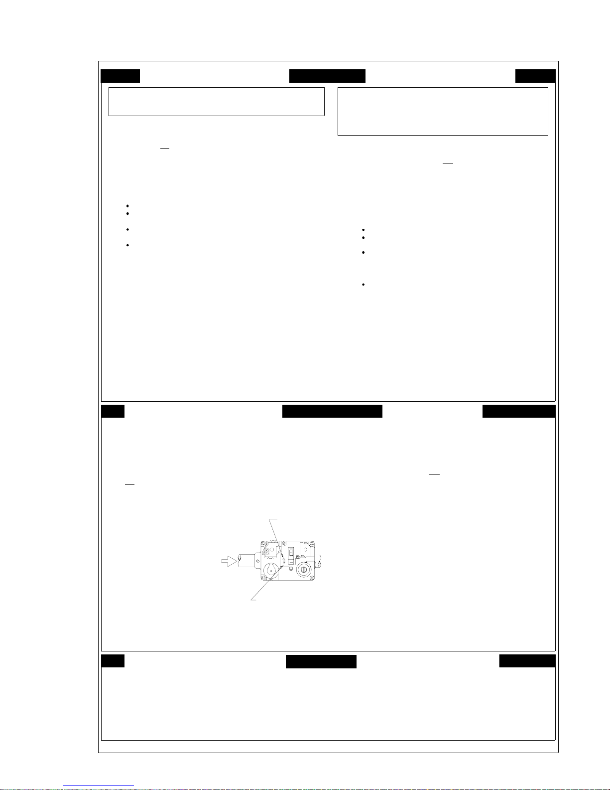
LIGHTING INSTRUCTIONS
F
O
Y
O
R
U
R
E
A
B
E
D
n
o
d
u
o
y
W
A
R
lo
p
x
e
s
n
o
s
r
e
p
a
s
i
T
h
A
.
w
a
h
it
b
u
h
e
t
B
B
E
O
F
.
e
a
r
a
b
a
u
e
c
le
t
t
e
s
H
A
W
p
If
c
U
o
e
s
C
.
N
e
r
e
v
d
,
a
n
h
h
n
e
c
t
p
x
e
r
o
D
o
n
o
D
.
m
e
m
I
a
p
h
e
t
m
e
t
s
y
s
f
I
N
IN
G
:
io
a
p
n
o
f
s
o
T
D
D
d
Im
n
d
ic
lo
t
d
p
e
r
m
y
a
n
l in
y
ju
r
d
p
lia
e
c
n
g
i
io
n
t
i
n
.
r
n
e
r
D
o
O
R
E
P
E
B
.
s
g
a
r
e
e
m
o
s
e
lo
f
e
h
t
n
D
T
O
O
tr
y
t
o
n
o
u
o
t
t
o
n
o
e
u
s
o
n
o
t
e
t
a
m
i
e
d
F
o
.
n
e
h
o
y
c
o
u
n
a
e
r
i
f
th
e
ll
a
y
y
l
h
u
r
o
s
l
o
o
t
e
s
u
t
't
o
n
t
y
r
c
r
F
o
ia
.
n
n
.
o
i
s
h
e
t
u
s
s
i
e
ly
c
t
a
a
i
ia
e
c
n
l
a
y
n
a
d
a
n
u
a
c
lt
u
s
f
o
lo
s
s
o
r
o
h
a
t
n
o
s
e
ic
v
d
e
w
e
h
g
li
o
t
y
r
t
o
t
n
N
R
G
A
I
T
s
t
o
e
m
u
r
s
h
e
is
s
a
g
a
.
r
o
Y
O
U
F
I
o
t
ll
n
a
a
ll
n
y
n
a
lig
t
h
le
e
n
y
a
h
c
n
a
e
o
n
p
h
y
a
ll
r
o
u
c
y
ly
e
h
t
w
o
a
g
y
h
a
r
c
e
t
o
m
t
r
p
a
d
e
e
s
u
p
o
d
t
n
v
e
l
h
e
t
f
.
I
e
it,
r
a
ir
e
o
p
m
e
t
t
a
o
e
r
p
if
lia
p
e
c
n
e
i
if
l
a
q
u
a
la
e
p
r
o
t
d
o
r
t
o
n
c
s
g
a
S
R
A
F
E
T
Y
F
O
O
R
E
P
E
R
N
A
G
T
I
llo
o
f
w
t
o
in
s
g
life
.
a
e
v
ic
h
a
u
h
e
h
t
t
e
m
s
n
e
ll
h
t
ie
v
r
S
M
E
a
l
p
p
r
t
c
s
ic
o
y
in
g
a
s
p
u
s
s
g
r
o
u
.
n
t
o
in
h
w
ill
r
a
l
l
a
c
e
t
p
r
d
p
y
a
n
d
s
v
e
r
a
n
e
c
w
l
h
ic
e
s
e
h
t
t
r
e
p
o
r
p
y
is
t
I
lo
t.
i
p
e
o
t
y
ic
ll
a
a
t
m
b
e
y
r
n
u
r
b
ll
n
u
o
a
r
l
l
a
to
t
e
x
f
e
h
t
n
d
a
ir
a
n
a
G
L
L
A
S
ia
e
.
n
c
h
;
c
t
w
i
in
d
il
b
u
g
r
u
o
r
f
e
r
p
li
u
p
s
a
r
y
r
in
t
's
s
r
e
li
p
r
e
p
li
p
u
s
s
g
e
h
t
n
r
u
t
in
h
u
s
p
t
o
n
u
a
q
s
ie
d
f
li
y
a
m
a
ir
p
e
t
a
r
b
h
a
s
n
ic
h
c
e
t
e
c
i
p
t
a
r
h
t
o
f
b
s
h
a
e
e
h
io
n
t
in
c
u
tr
s
d
m
a
,
e
g
a
ip
q
u
e
d
p
lig
s
t
h
h
d
.
a
n
lia
p
p
a
e
h
n
t
d
lo
r
o
w
ill
.
e
ig
n
h
a
m
o
b
t
u
c
io
.
n
s
,
l le
o
r
n
t
o
c
a
s
r
u
t
r
o
y
b
n
ic
v
e
r
e
a
n
i
u
lt
e
s
r
e
e
ia
e
n
i
f
w
a
r
d
e
u
n
n
o
in
t
n
s
p
e
l
o
r
n
t
o
c
w
a
r
d
e
n
u
te
A
R
V
A
E
I
L
s
c
e
's
r
v
.
e
r
e
r
.
r
e
t
t
c
.
r
A
V
S
S
E
le
la
t
is
u
q
r
a
r
t
n
e
p
r
o
c
C
e
A
.
u
m
a
u
d
'a
A
B
.
V
e
n
r
u
n
e
c
p
e
Q
U
N
e
C
.
q
u
S
i
é
p
r
e
n
t
d
é
N
e
D
.
d
a
e
c
t
r
e
m
o
u
t
E
R
r
t
e
n
î
r
o
a
t
n
o
t
llu
A
if
e
a
t
r
v
u
E
p
'à
la
a
e
t
le
c
p
s
n
h
n
p
e
t
M
T
I
E
u
le
in
r
s
e
t
s
c
le
e
h
c
é
d
d
i d
m
le
o
o
r
a
c
e
n
a
ll
e
p
p
'u
a
e
m
N
r
e
d
in
s
n
e
F
N
N
n
A
e
R
o
f
S
in
s
u
m
la
m
a
;
r
e
e
d
n
c
s
'e
l
i
c
i
la
c
o
c
m
a
d
s
e
d
t
p
la
o
s
e
u
r
a
e
c
n
o
e
il
is
it
d
o
s
p
n
i
t
n
t
e
m
e
q
u
le
û
u
b
r
e
l
r
T
D
E
L
E
o
t
a
u
u
t
o
t
r
u
u
.
z
a
g
e
d
r
s
z
g
a
t
n
o
'
s
t
u
m
c
c
a
u
S
R
E
A
I
s
a
p
e
t
e
n
t
r
h
e
u
c
o
t
e
a
is
r
il
e
'u
t
u
m
m
i
le
e
p
p
r
a
y
o
l
p
m
e
n
s
e
à
e
r
t
e
c
p
u
r
e
s
s
i
n
r
u
e
n
n
o
s
r
e
p
i
d
e
ie
n
c
.
s
u
o
t
u
o
e
r
s
n
a
in
;
ja
e
e
t
e
s
e
r
tt
e
n
le
p
e
a
p
r
u
m
la
e
r
c
o
r
f
u
r
h
e
x
e
e
n
d
ir
v
r
e
s
e
s
u
,
a
è
l
p
m
o
c
ié
f
a
li
u
q
n
e
u
o
t
e
r
r
p
a
t
m
q
d
e
a
n
m
N
T
E
N
M
A
R
Q
ic
u
N
tio
r
e
m
if
e
l
r
F
d
R
l
p
le
'IL
e
r
a
u
c
é
n
la
d
n
n
r
m
n
t
a
p
e
e
t
p
e
ti
u
o
T
:
le
s
n
a
d
s
n
in
d
n
e
c
n
u
e
g
a
m
r
p
d
b
m
e
u
r
u
n
t
e
e
a
c
o
l
c
o
i
a
m
s
ie
v
e
d
e
t
s
d
e
p
a
s
t
r
o
'a
g
e
a
lu
m
l
N
e
.
le
û
r
u
r
u
a
n
e
m
e
e
ll
R
E
A
I
F
ie
'a
l
r
p
a
p
l
è
s
r
p
le
if
e
n
r
u
q
s
d
lo
u
r
s
iv
n
a
u
e
u
a
A
U
Y
N
'a
d
llu
l'a
m
e
r
r
e
in
t
n
u
c
u
r
n
h
o
p
é
té
l
n
t
e
m
e
d
ia
t
é
lé
o
n
p
h
t
le
le
le
s
tr
e
t
.
a
z
g
n
p
d
o
é
r
e
a
,
le
r
r
e
le
i
v
lo
p
e
m
e
is
o
in
c
e
n
e
,
é
ic
h
q
n
e
c
ie
n
te
e
t
n
e
d
u
o
n
u
u
o
io
s
n
a
p
p
a
e
t
i
e
r
n
e
o
u
m
t
e
n
p
s
n
i
r
u
e
t
c
e
s
d
u
tè
s
y
m
p
é
t
é
t
n
o
lo
E
T
T
R
M
D
E
C
H
E
L
n
e
u
q
n
e
e
s
é
p
r
u
u
o
ie
ie
ls
r
é
,
t
m
u
h
in
a
e
e
ill
u
v
e
lu
a
m
l
i
q
u
e
n
t
a
s
p
.
t
n
O
N
C
T
é
d
u
r
p
o
p
la
n
d
u
e
l'a
t
r
e
i
d
u
l
s
.
o
O
D
E
p
a
p
ie
l
r
é
le
p
te
u
r
le
s
n
d
a
e
i
n
r
o
u
f
le
v
n
ú
d
e
in
s
io
t
c
u
r
t
le
le
p
e
p
r
is
s
d
'a
m
d
d
'o
u
ti
r
à
l
n
e
t
s
p
a
a
lif
u
ié
.
p
a
e
r
la
in
e
c
d
n
'il
s
l
a
é
té
a
p
ie
.
t
r
l'a
a
p
p
r
e
d
e
n
o
c
d
a
é
s
n
g
E
R
E
I
s
e
r
e
p
m
t
n
n
a
e
n
e
p
x
lé
s
e
d
.
s
e
e
l
I
.
e
s
e
e
r
t
IO
N
N
e
le
c
r
c
,
r
h
e
c
E
U
R
D
iq
e
u
r
t
c
im
t
b
â
d
u
r
e
s
s
i
o
in
s
.
u
d
s
n
ic
v
r
e
s
u
d
n
o
i
ff
e
t
e
c
la
e
d
r
e
t
Q
u
ic
n
o
p
e
e
r
u
r
ie
.
p
lo
g
n
e
A
l
p
e
p
e
t
l
i
e
r
e
le
ô
r
t
l'e
a
n
s
á
s
a
p
te
c
l
e
u
lo
io
s
n
io
s
s
n
t
s
E
R
,
a
r
E
G
A
Z
;
t.
e
n
a
z
g
e
s
d
e
e
g
a
z
.
t
e
e
u
q
t
é
u
n
r
t
u
.
O
P
E
N
R
A
G
T
I
N
S
T
R
I
U
1
.
S
T
O
P
!
R
t
d
e
h
t
2
S
e
.
T
u
3
.
T
4
.
h
d
e
D
o
P
5
.
u
D
o
W
6
.
s
m
t
h
in
o
n
g
a
7
P
.
u
o
t
R
8
.
e
T
9
u
.
p
o
0
.S
1
e
1
1
f
.I
o
f
O
s
e
S
.
1
u
T
.
2
s
if
P
.
3
D
R
.
4
a
la
is
b
.
l
e
s
o
th
m
r
e
h
e
t
t
f
o
f
n
r
a
ll
o
w
p
e
is
e
n
c
a
li
p
p
a
is
w
i
h
e
c
i
v
n
h
s
n
a
it
e
ll
n
e
th
e
h
t
,
s
h
s
O
"
p
la
n
r
w
e
t
t
e
h
t
llo
w
G
f
f
ic
v
r
T
t
t
e
n
r
e
s
u
n
o
p
e
u
a
h
c
o
t
y
r
t
o
t
li
h
g
o
c
a
s
g
e
h
t
e
.
c
o
r
f
o
t
in
m
5
)
(
iv
e
f
n
i
,
s
g
a
r
o
f
,
s
g
a
l
l
e
m
s
e
f
a
s
in
.
y
f
t
o
y
if
la
l
is
e
b
e
n
o
t
o
g
o
h
r
h
la
s
t
x
o
r
c
a
s
g
n
t
o
N
.
"
e
s
a
e
c
s
c
c
a
ll
le
e
t
n
c
a
h
e
p
p
t
o
t
r
e
to
t
a
t
s
o
m
r
lia
p
p
a
e
w
n
c
th
e
u
r
in
t
s
A
p
p
T
o
a
s
e
c
t
e
ic
h
n
ia
O
T
U
R
N
t
e
h
o
m
r
e
h
ll
a
e
f
f
o
le
is
ic
v
e
o
t
g
th
e
s
a
.
e
c
r
o
f
t
o
r
c
e
t
c
n
o
in
f
y
e
t
f
a
s
e
h
o
t
t
a
t
lo
w
e
s
a
h
e
p
p
t
o
t
r
ip
q
u
e
p
w
e
d
a
lly
lig
c
i
t
a
m
o
t
e
r
b
n
h
e
r
u
t
t
le
o
l
v
r
n
t
o
t
e
r
e
l
c
o
t
s
e
u
t
a
lu
c
d
r
e
a
n
in
g
S
F
o
T
llo
O
P
!
b
a
io
n
t
a
m
r
o
d
u
e
t
le
l
p
ic
r
lia
tio
c
a
li
n
s
c
b
o
c
o
e
m
s
't
n
o
.
p
e
v
r
a
e
l.
n
c
n
.
e
e
s
e
d
ir
s
d
e
o
n
ill
o
r
e
p
t
T
T
o
"
s
n
a
e
"
d
n
n
c
o
c
a
s
g
o
r
O
G
F
F
o
lo
t
ta
t
w
ic
p
r
w
o
e
t
m
fo
r
r
e
p
e
le
l
o
v
r
t
n
a
l
p
s
s
e
c
c
C
T
IO
N
S
1
.
A
R
R
m
r
o
o
i
t
a
tin
e
t
s
g
t
ia
n
l
e
.
c
i
a
n
h
t
i
t
s
h
t
e
h
n
h
a
b
y
O
F
"
F
"
a
u
n
t
o
r
th
lo
e
f
o
B
"
"
w
e
v
o
ll
G
A
S
N
E
L
I
A
R
R
G
D
U
t
t
in
g
.
e
,
a
t
n
u
r
a
u
ll
r
o
c
y
m
y
n
p
a
.
T
A
S
s
t
s
e
tt
e
th
to
e
r
.
d
e
o
t
r
e
O
"
l.
e
n
a
n
o
e
o
v
b
a
n
.
.
n
itio
g
n
.
e
r
n
u
r
b
.
d
tio
i
P
o
s
.
n
T
e
n
h
.
a
s
g
y
o
y
f
.
I
r
u
T
V
E
E
I
A
Z
O
A
P
P
L
in
.
g
a
lia
p
p
e
c
n
P
s
o
F
F
"
R
M
*
O
F
F
O
*
A
N
U
M
A
E
L
V
S
E
R
O
N
I
P
O
N
A
N
C
I
E
io
it
.
n
p
o
la
R
le
é
g
2
.
.
3
.
C
p
o
u
a
t
C
e
4
.
d
'a
u
ll
a
llu
m
P
s
o
u
5
.
s
p
o
it
n
e
t
A
t
6
.
.
z
g
a
p
la
n
c
G
A
A
O
N
E
B
T
I
A
N
U
O
N
"
/
*
M
1
3
P
C
2
N
*
G
A
L
H
O
W
T
I
S
I
Z
P
E
O
N
S
E
,
L
M
A
R
C
*
*
*
S
N
O
N
A
R
R
H
E
"
l
r
u
s
n
S
'il
P
o
7
.
s
u
it
s
p
o
R
e
m
8
.
tt
e
M
9
.
R
le
é
g
0
.
1
1
1
l'a
S
i
.
u
r
t
s
n
i
g
d
e
if
l
a
q
u
R
.
1
g
é
C
.
2
u
o
t
u
a
f
P
u
o
.
3
s
o
p
N
e
R
.
4
m
e
M
le
s
L
is
z
e
E
Ê
T
R
!
d
ie
e
u
r
r
é
u
p
s
n
o
i
t
r
le
r
h
e
t
l'a
e
r
lim
a
r
p
p
il
e
a
e
g
a
m
le
b
e
r
û
r
e
le
s
le
v
.
n
o
i
q
n
i
c
e
r
d
R
le
n
if
e
r
u
o
,
p
r
h
e
E
E
T
R
io
n
p
t
a
r
o
a
'y
s
a
p
e
le
s
le
v
.
n
o
i
n
e
e
r
e
tt
'a
p
a
p
l
e
r
r
le
h
e
t
il n
e
a
r
p
p
io
t
c
in
s
n
l'a
e
d
z
a
l
o
é
u
i
e
P
O
U
D
E
le
le
r
h
t
l'a
lim
r
e
p
d
é
c
o
p
r
le
e
s
s
io
it
.
n
c
r
o
f
s
a
p
tt
e
e
e
r
e
l
à
t
a
t
s
o
m
r
é
io
n
t
a
n
t
e
é
e
r
a
g
n
é
m
to
u
iq
m
e
u
a
t
n
u
a
m
le
r
u
d
r
e
i
c
u
n
o
m
)
5
(
e
in
t
u
u
o
u
t
a
t
u
o
t
e
l
c
d
é
r
e
r
s
P
a
s
!
à
r
e
u
s
u
r
e
i
r
é
p
d
d
'o
r
e
u
e
d
c
d
u
n
o
r
e
i
a
p
le
la
p
e
c
e
il
o
u
s
r
te
s
l
à
t
a
t
s
o
m
r
t
e
m
e
s
e
p
C
u
lé
it
.
s
e
t
i
e
e
r
p
p
a
e
t
l
n
is
e
s
r
r
u
o
f
C
R
O
U
G
A
Z
t
a
m
t
s
o
r
e
io
t
a
t
n
e
d
à
r
e
s
e
le
ie
v
c
d
u
r
.
r
e
la
p
le
e
c
n
R
C
H
E
u
r
in
t
s
e
t
t
e
c
e
m
t
a
l
tr
iq
c
e
d
t
n
a
t
n
,
e
pas
e
lle
m
d
e
l
ô
r
t
u
p
o
s
l'
e
d
r
o
n
e
u
l'é
p
a
t
c
d
e
e
,
z
g
a
ô
r
t
d
e
l
n
e
n
a
n
o
i
n
s
e
m
t
a
e
n
a
s
o
m
m
e
le
p
p
d
e
r
u
P
E
R
D
E
L
la
à
le
é
n
a
r
é
p
o
r
t
n
o
p
n
a
s
d
s
n
o
e
i
t
c
.
e
t
iq
e
t
u
é
t
r
p
é
e
la
r
u
a
t
l'a
e
d
p
p
e
u
d
é
o
t
y
s
'u
n
e
y
a
s
s
e
.
t
e
n
à
z
g
a
u
O
"
la
e
is
e
c
r
s
r
y
l,
i
e
a
r
p
a
p
z
g
a
d
e
r
e
u
d
p
ô
s
n
i
e
s
d
B
e
é
tt
e
e
tiq
u
e
a
'é
l
à
r
e
s
s
à
z
g
a
u
"
O
.
'a
s
d
é
c
c
u
.
p
g
c
e
d
a
e
tu
r
r
é
s
e
,
h
c
r
a
m
n
e
p
le
u
o
c
t
n
ic
h
c
e
t
n
u
r
.
z
a
'A
L
D
M
'A
P
P
A
R
m
e
t
tu
a
r
é
p
d
iq
e
u
r
t
e
'e
d
n
io
s
n
t
z
a
g
u
d
le
e
n
'a
d
c
u
a
r
u
s
é
it
r
u
c
é
e
s
a
s
b
s
u
l
p
l.
i
e
a
r
e
m
è
t
s
à
r
A
R
R
E
F
/
F
T
"
h
a
m
o
c
S
.
u
r
t
te
t
a
t
N
r
i
s
y
i
u
l'a
r
ie
S
I
E
e
r
l'a
r
t
à
è
c
.
/M
e
le
t
o
u
t
e
r
p
p
s
è
p
r
is
r
p
c
i
io
t
c
e
p
e
é
e
r
d
n
S
u
d
,
s
a
c
le
'e
t
s
s
n
u
iv
s
A
R
C
.
le
s
m
is
s
O
N
I
ié
it
r
u
c
é
s
e
d
é
t
n
a
.
H
E
"
io
n
IL
s
s
a
b
lu
p
la
s
re
a
p
p
ie
.
n
t
O
F
F
"
.
s
.
e
il
'il
s
A
R
R
/
E
T
"
0
2
7
7
1
7
0
1
A
M
E
N
S
E
I
15

LIGHTING INSTRUCTIONS
16
E
N
O
T
R
I
B
N
L
E
A
,
U
M
M
/
"
N
O
OFF
OFF
ON
ON
N
N
I
I
I
I
S
S
P
P
2
2
A
M
U
N
W
S
T
I
N
I
"
Z
A
G
S
O
E
P
N
"
C
R
E
H
A
S
A
G
E
L
N
T
I
E
I
R
E
V
R
A
Z
A
G
U
D
L
A
A
G
S
H
C
O
N
H
W
S
O
"
N
P
S
O
A

LIGHTING INSTRUCTIONS
F
O
Y
O
R
U
R
E
A
B
E
D
F
n
o
d
u
o
y
N
f
D
D
d
I
p
I
c
r
m
io
T
m
f
ic
d
a
p
n
R
o
on
o
h
a
u
don
lo
p
ner
r
o
o
y
ia
u
i
IN
n
l in
lia
g
i
E
gas
e
T
not
m
one
o
ll
y
s
s
s
a
ia
l
a
n
n
y
e
n
i
t
n
n
s
t
O
edi
u
he f
t
on.
e
e
n
G
m
n
.
o
h
o
o
our
't
.
ly
d
ju
t
i
O
e
t
t
.
c
ool
t
For
t
c
a
c
io
D
.
m
D
t
u
ann
t
r
h
e
a
:
y
y
r
e
n
o
P
B
e
lo
f
r
t
ouc
s
t
a
F
i
h
y
s
i
a
c
n
O
y
o
r
a
I
d
E
e
e
e
e
s
t
c
y
f
r
e
o
o
d
o
n
R
g
o
o
t
a
ly
o
ll
o
and
.
o
e
app
ll a
d
n
g
s
r
e
e
t
u
s
s
a
.
r
F
I
h
n
w
t
dep
f
I
r
o
a
v
A
lig
c
e
lo
s
t
a
y
r
th
q
t
s
u
n
ic
y
r
T
e
r
s
i
Y
n
a
ll
t
eac
o
t
pair
a
r
lia
u
o
lt
s
e
I
O
h
y
pho
h
a
e
n
a
r
c
s
o
t
N
t
h
t
y
e
r
t
e
ont
c
o
t
p
l
t
l
t
w
o
a
e
our
h
m
e
e
c
if
p
u
a
o
f
hav
h
ic
li
g
G
m
s
e
a
v
U
y
n
le
e
n
a
g
y
e
s
u
v
e
t,
i
m
i
e
ie
d
a
l
o
r
W
A
R
lo
p
e
x
s
n
o
s
r
p
e
a
s
Thi
A
.
a
w
h
it
bur
h
e
t
B
B
E
F
O
.
ea
r
a
b
aus
e
c
e
l
t
t
e
s
H
A
W
onl
U
e
s
C
.
N
e
e
v
d
,
han
h
n
e
c
t
p
x
e
r
o
not
D
o
D
.
m
e
m
I
app
h
e
t
e
t
s
y
s
S
c
s
our
n
h
c
p
f
c
o
s
life
h
s
ie
t
g
r
e
l
S
R
A
F
E
T
Y
O
O
R
E
P
E
R
N
A
G
T
I
llo
o
f
t
w
e
s
e
h
t
e
r
p
o
r
p
in
g
ty
io
s
in
d
a
n
t
tr
c
u
s
m
,
e
g
a
.
i
t
I
.
lo
t
i
p
a
e
h
a
u
t
m
o
u
b
he
t
t
ll
e
m
l
l
a
t
e
x
n
e
ll
air
han
t
r
M
E
L
L
ia
n
c
l
p
a
p
c
t
w
s
i
ic
r
b
our
y
in
a
upp
s
s
r
e
li
p
p
u
s
g
s
s
a
.
t
r
o
in
r
u
t
ll
t
o
w
n
i
u
a
q
a
l
l
a
t
a
p
e
r
e
d
par
y
a
n
t
e
c
i
v
e
r
s
a
p
any
w
h
h
ic
h
G
a
r
t
e
h
u
n
p
ir
t
ner
a
o
u
lie
's
p
li
has
e
r
t
a
t
A
.
;
u
f
s
ic
r
t
il
t
ie
m
c
o
a
und
o
h
and
S
d
r
in
p
lie
he
h
s
d
a
h
f
bee
ip
equ
ped
s
ll
b
e
n
i
r
f
s
n
th
y
b
t
s
ic
y
y
lo
f
g
o
u
r
,
r
gas
in
e
r
een
e
lig
han
w
.
m
e
ia
n
s
t
h
d
.
anc
li
app
e
h
t
r
o
l
il
a
c
io
t
c
t
r
o
ic
v
r
u
s
u
n
ont
c
nde
u
neig
n
o
u
e
lt
o
t
s
n
r
i
nde
r
e
h
's
o
r
b
.
le
l
o
v
r
t
e
y
b
n
n
e
r
i
f
a
e
w
t
a
r
in
t
pec
s
l
o
w
a
r
.
r
e
t
A
R
V
A
E
tio
m
if
l
r
le
e
a
c
n
d
m
p
e
t
E
N
r
m
e
d
e
ma
F
de
R
u
l
'IL
r
u
u
é
t
la
e
n
ner
c
a
l
e
t
pou
e
i
N
T
N
M
A
R
Q
ic
u
o
T
:
le
s
n
a
d
s
n
n
d
e
c
in
n
u
g
e
a
a
m
s
ie
v
e
d
e
t
r
p
b
r
n
a
e
t
o
c
e
d
e
o
n
d
'
s
d
c
le
s
e
m
o
r
o
l
a
û
r
A
l
n
lo
u
a
Y
'a
u
t
ia
le
gaz
r
is
in
c
e
io
t
ent
r
u
n
t
lu
n
'a
if
n
é
t
épo
le
h
t
le
I
llu
t
é
t
e
c
t
app
i
t
e
u
ppa
le
u
n
l
e
t
n
e
n
n
s
m
e
R
A
in
é
lé
r
.
le
m
ée,
é
u
r
iv
m
e
ic
s
y
p
age
r
ll
E
r
d
m
t
p
pho
o
ou
o
p
s
é
t
a
.
e
p
s
eau
U
e
hon
ent
le
n
v
p
ie
u
a
u
e
e
t
s
r
r
d
i
lo
ne
è
p
s
d
N
e
e
m
F
ie
l
è
s
u
q
N
l'a
r
r
upt
r
n
s
app
,
r
e
e
qua
n
de
n
u
i
e
r
e
e
t
c
m
lo
E
T
T
R
M
D
E
C
H
E
L
e
n
q
u
n
e
e
s
p
é
r
u
u
o
ie
ie
ls
r
é
,
t
m
u
h
in
a
e
e
ill
v
eus
lu
m
l
a
i
q
u
ent
t
pas
.
t
n
O
N
C
T
é
d
p
our
p
la
d
n
u
t
e
l'a
r
e
i
d
l
.
o
s
u
O
D
E
p
a
p
riel
é
le
u
r
e
l
s
n
d
a
e
e
s
i
n
our
f
le
o
v
n
ú
d
e
in
s
io
t
c
u
r
t
le
le
e
r
is
d
'a
s
m
d
d
'o
u
t
r
à
il
ent
t
s
p
a
lif
ié
.
Q
p
a
e
r
la
in
e
c
ndie
é
'il
é
s
t
l
a
a
p
n
ie
.
t
r
l'a
a
p
p
r
e
d
e
co
n
dan
n
gés
E
R
E
I
s
e
r
e
p
m
t
n
a
n
n
e
p
e
x
lé
s
e
d
.
s
e
s
e
l
I
.
e
e
e
r
IO
N
N
e
le
c
r
a
c
h
er
c
,
E
U
R
D
iq
ue;
r
t
c
m
e
i
bât
de
u
r
e
s
is
in
.
u
d
s
n
ic
v
r
e
s
u
d
on
i
f
f
e
t
e
c
la
e
d
r
e
u
ic
n
q
o
peu
e
r
r
.
p
lo
g
n
e
A
l
ppe
e
t
l
i
e
r
t
e
le
ô
r
t
l'e
u
a
s
á
s
a
p
te
c
l
e
u
lo
io
s
n
i
s
s
n
o
t
E
R
,
r
E
G
A
Z
.
t
n
a
z
g
s
d
e
e
g
a
z
.
t
e
e
u
t
é
u
n
r
.
I
L
A
V
S
E
S
R
E
T
M
I
n
e
a
t
e
T
t
s
t
F
'u
n
o
s
m
ane
;
her
s
a
e
i
e
c
m
s
d
t
s
r
n
i
que
r
o
gaz
s
A
e
e
ppe
e
u
i
c
s
a
app
f
e
u
n
d
e
l
D
u
r
'a
til
e
s
r
p
e
e
o
r
m
in
é
o
il
d
e
t
d
I
p
ouc
t
m
p
n
e
ndie
r
in
t
r
s
,
q
t
c
e
is
b
aut
e
c
R
a
is
l
e
i
r
ou
;
e
t
c
u
e
c
uali
o
and
s
le
s
u
ne
pos
m
r
E
s
c
s
e
e
p
c
s
s
s
e
e
ne e
r
o
u
E
r
t
c
u
h
e
c
m
a
d
p
la
o
c
t
i
n
t
e
u
e
l
û
L
E
o
r
u
.
z
a
g
t
n
o
p
u
m
u
S
E
ent
t
her
a
r
u
m
m
i
r
a
y
o
l
à
e
r
t
eur
n
ne
o
.
s
our
t
n
ja
e
e
t
s
e
r
le
r
un
m
la
r
x
d
ir
v
è
l
p
m
ié
f
par
t
qui
e
le
e
r
t
le
la
t
is
d
e
q
u
r
e
a
r
t
e
n
a
n
î
ll
e
r
o
p
r
o
c
app
C
t
e
A
.
d
'u
uni
m
o
m
a
aut
d
'a
m
u
ll
A
B
.
V
A
N
le
if
e
n
r
r
deu
o
une
a
in
t
r
e
c
n
e
v
peu
Q
U
E
N
N
n
A
e
.
r
.
r
C
D
R
f
S
in
N
pou
e
.
la
qu'à
S
m
la
i
r
e
r
a
é
p
r
e
n
t
de
e
t
le
déc
n
c
a
p
N
e
s
.
'e
l
s
dan
h
e
c
t
c
i
n
e
m
r
p
la
e
out
t
o
c
M
E
N
S
E
I
i
R
'y
i
e
p
it
p
E
t
e
m
e
s
o
d
her
E
s
o
e
c
é
i
le
p
p
s
i
r
r
r
e
n
r
enif
p
e
n
t
t
par
t
P
e
s
io
a
e
T
o
a
e
a
r
l
le
io
r
le
.
T
o
.
'a
d
ou
r
s
tt
M
le
L
is
z
e
Ê
R
!
ie
e
u
r
r
upé
s
n
h
t
l'a
lim
a
r
e
e
g
b
le
le
le
n
i
c
e
l
p
,
E
R
o
i
t
r
a
p
le
le
e
e
p
p
h
t
i
e
s
n
l'a
e
l
O
U
D
le
l'a
r
é
c
o
le
e
.
n
o
f
e
r
e
il
aut
r
r
our
n
s
n
a
e
l n
e
t
r
r
m
û
v
q
!
v
r
r
in
p
R
E
h
lim
d
le
c
e
à
t
a
t
s
o
m
io
n
t
a
n
t
e
a
ger
n
é
iq
o
m
a
t
a
m
le
r
u
d
r
e
i
o
c
u
m
)
5
(
in
u
au
o
t
t
u
o
t
e
c
d
é
ler
P
s
a
s
r
e
u
s
eur
i
r
é
p
de
d
'o
r
e
u
d
o
c
du
r
e
i
le
la
p
e
c
e
il
o
u
s
s
à
t
a
t
s
o
m
e
m
e
s
e
u
lé
it
.
s
e
t
e
per
e
l
i
n
is
s
r
r
u
o
f
C
O
U
G
A
Z
m
t
s
r
e
o
io
t
a
t
n
e
à
r
e
e
d
ie
v
d
r
u
.
r
e
la
p
e
c
n
s
d
e
é
é
u
n
uelle
n
t
u
à
n
ann
p
te
t
a
t
e
a
s
le
i
a
l
e
l
t
e
t
e
r
u
l'é
e
t
a
l
pas
C
u
P
D
t
n
o
c
n
c
c
a
,
ô
r
s
de
n
de
g
ô
r
n
o
ppe
r
à
p
o
p
s
e
e
t
t
n
n
l
pou
e
t
a
l
s
e
t
m
de
E
E
é
n
r
t
t
t
m
iq
r
t
e
m
e
ode
ape
z
e
e
o
i
m
en
m
R
L
la
le
é
t
a
u
l'
,
a
n
le
r
r
n
e
dot
pas
d
app
c
d
c
a
ô
c
p
u
p
g
ue
ent
u
r
e
p
u
.
e
r
t
n
é
m
'A
e
t
t
A
R
C
H
E
r
u
s
é
it
r
u
c
é
s
de
s
n
o
i
t
.
e
t
iq
uet
t
é
la
e
r
u
a
t
r
l'a
e
d
p
par
é
y
s
d
'u
n
y
a
s
e
s
r
e
.
à
gaz
O
"
c
e
la
is
e
r
s
c
y
l,
i
e
a
r
z
g
a
de
r
u
t
s
n
i
e
s
d
B
iq
é
e
u
t
t
t
e
t
a
'é
l
à
r
e
s
s
à
g
z
a
"
O
'a
.
d
s
é
c
c
des
e
r
u
a
t
r
é
s
u
he,
c
r
a
n
uple
o
c
r
t
n
ic
h
c
e
t
n
u
.
z
a
'A
L
D
M
I
P
P
A
R
m
tu
a
r
é
p
d
iq
e
u
r
e
l'a
'e
d
n
io
s
n
a
z
g
u
d
le
e
'a
d
c
a
u
s
c
p
F
h
.
r
t
t
N
S
r
t
t
à
o
u
e
ape
i
i
l'a
i
e
E
e
r
à
è
e
s
bas
s
u
l
l.
i
e
e
m
è
A
R
R
E
/
F
a
m
S
r
y
c
.
/M
T
"
e
l
t
o
u
t
per
p
è
p
r
is
r
p
c
i
io
t
e
é
e
r
d
m
n
S
u
d
s
,
s
a
c
le
'e
t
s
d
s
n
u
iv
s
A
R
C
.
le
s
s
s
i
O
N
I
ié
it
r
u
c
é
s
e
é
t
n
a
.
H
E
"
io
n
IL
s
b
a
lu
p
la
s
r
a
p
p
ie
n
t
e
O
F
"
.
s
e
.
s
il
e
'il
s
.
A
R
R
E
T
/
F
"
2
1
1
7
2
7
0
1
O
P
E
N
R
A
G
T
I
N
S
T
R
I
1
.
S
T
O
P
!
R
ead
2
3
4
5
6
7
8
9
1
1
1
2
3
4
la
h
is
b
t
.
.
.
.
.
.
.
.
0
1
.
.
.
.
dev
D
P
D
W
s
t
in
on
gas
P
t
R
T
pow
S
.
I
.
f
O
s
S
T
T
hen
o
f
o
S
T
if
P
D
R
e
u
r
h
is
o
u
s
o
a
m
t
u
s
"
epla
u
r
e
t
h
t
llo
f
f
r
e
e
u
s
u
o
e
t
e
he
t
v
t
r
s
n
i
not
h
not
it
h
,
h
O
n
t
e
G
T
t
n
e
p
t
c
ll
e
h
w
ic
h
n
he
o
app
e
f
s
is
g
N
on
r
a
O
h
r
o
la
f
he
t
iv
o
f
m
s
o
gas
c
t
e
app
t
s
e
e
o
v
th
c
.
l
e
o
th
m
r
e
f
a
ll
pow
e
anc
li
w
i
h
u
a
h
c
o
t
tr
y
ght
li
c
a
s
g
e
.
fo
c
r
in
m
5
)
(
e
n
i
,
gas
r
,
gas
l
l
e
f
a
in
.
y
e
t
if
y
la
l
e
b
e
n
o
t
t
x
r
n
t
o
c
.
"
e
s
c
c
a
e
a
ll
le
e
c
a
pplia
he
t
o
t
a
t
s
o
m
r
e
anc
li
h
e
u
r
in
t
s
T
A
p
p
o
e
c
t
ic
h
n
T
U
R
t
m
e
r
h
ll
a
e
f
f
le
is
ic
e
o
t
e
s
g
a
.
e
c
r
o
f
t
e
c
t
o
n
t
s
is
ont
f
s
o
s
t
t
ia
N
r
he
t
e
t
u
c
S
o
ou
l
r
o
w
c
li
o
c
b
c
o
y
e
t
f
a
s
o
t
t
a
lo
w
app
he
t
o
t
r
ip
q
u
e
p
ed
a
lly
c
i
t
a
m
o
ner
bur
th
e
le
o
l
v
r
e
l
c
o
t
s
e
t
d
u
l
ear
n
in
g
F
T
O
P
!
io
n
t
a
m
r
d
s
't
n
o
.
e
p
t
le
e
v
r
p
a
nel.
ic
c
n
.
e
ired
s
d
e
o
n
ill
o
p
t
T
o
"
io
s
n
t
a
a
n
e
"
n
c
a
s
g
o
r
n
O
F
F
lo
o
t
ta
s
t
ic
p
r
w
o
t
fo
r
e
p
e
le
l
o
r
t
n
o
a
l
e
s
c
c
U
C
T
IO
N
S
1
.
A
R
R
m
r
o
in
f
o
i
t
a
in
g
t
e
t
s
t
e
s
ia
n
l
e
.
c
an
h
t
w
i
t
s
ig
h
t
l
e
h
n
h
a
b
y
o
t
r
O
F
"
F
e
any
u
t
o
a
r
e flo
h
o
t
B
"
"
o
ll
o
w
e
v
b
o
a
l
l
e
m
G
N
I
A
R
D
t
t
e
s
in
g
.
e
,
a
t
r
e
n
T
u
r
a
ll
our
c
y
d
o
m
c
pan
.
y
G
T
A
S
w
t
e
s
tt
e
s
th
to
e
r
e
m
d
.
r
e
o
t
e
r
v
O
"
l.
e
n
a
p
s
n
o
e
o
v
b
a
n
.
.
ig
io
n
it
n
.
e
r
n
bur
.
d
io
.
n
t
P
i
o
s
"
T
hen
.
gas
o
y
f
I
.
r
u
A
S
E
L
T
V
E
R
E
I
G
U
A
Z
O
A
P
P
in
.
g
a
lia
p
p
P
F
F
"
R
O
B
A
N
U
M
O
N
"
L
N
I
A
N
C
I
L
E
e
c
n
io
it
o
s
.
n
por
a
l
R
égle
2
.
.
3
.
C
oup
app
C
e
t
4
.
d
'a
u
ll
a
llu
m
P
ous
5
.
s
p
o
it
n
e
t
A
t
6
.
.
z
g
a
p
la
n
c
G
A
N
E
T
I
E
N
E
,
L
A
R
C
M
H
/
A
N
U
M
A
L
E
V
S
E
R
O
P
O
N
A
Z
P
O
S
E
G
H
O
S
T
I
A
R
R
"
A
S
N
W
O
N
I
10.
1
a
l
r
u
s
n
S
'il
P
o
7
.
s
u
it
s
p
o
R
e
m
8
.
r
t
t
e
M
9
.
R
ler
é
g
1
l'a
S
i
.
u
r
t
s
n
i
gaz
d
e
if
l
a
q
u
R
1
.
é
g
C
2
.
o
u
t
u
a
f
P
3
o
.
u
s
o
p
N
e
R
4
.
e
m
17

LIGHTING INSTRUCTIONS
GAS
I
T
N
L
E
A
R
R
I
V
E
E
GA
Z
D
U
18
*
*
OFF
OFF
*
*
*
*
M
A
L
E
I
N
ROBIN
M
A
"
ON
ON
N
U
A
L
R SHOWN
V
E
"
O
N
N
"
U
ON/
*
*
GAS
PO
A
T
EN PO
RCH
A
*
*
*
*
Z
A
G
S
E
"
E
E
L
,
M
*
*
S

PRODUCT DESIGN
36"
Maximum
Overhang
36" Side
Clearance
for Servicing
Recommended
24" Clearance
(Condenser End)
Minimum 9" Clearance
to Combustibles
36" Clearance for
Service Required
In installations where the unit is installed above ground level and
not serviceable from the ground (Example: Roof Top installations) the installer must provide a service platform for the
service person with rails or guards in accordance with local
codes or ordinances or in their absence with the latest edition
of the National Fuel Gas Code ANSIZ223.1.
NOTE: The flue outlet hood and air inlet hood (Package Gas Units) are
packaged separately inside the unit and must be installed prior to operation.
NOTE: Units can also use roof curb (and platform for leveling, where
necessary) to utilize bottom discharge.
48" Minimum
Overhang
0" Minimum
Clearance to
Combustibles
Vinyl Coated
Canvas
Connections
Insulated
Return
Duct
Insulated
Supply
Duct
WARNING
T
O PREVENT POSSIBLE DAMAGE, THE UNIT SHOULD REMAIN IN AN UPRIGHT
POSITION DURING ALL RIGGING AND MOVING OPERATIONS.
LIFTING AND MOVING IF A CRANE IS USED, PLACE THE UNIT IN AN ADEQUATE
CABLE S LIDE.
T
O FACILITATE
IMPORTANT: If using bottom discharge with roof curb,
ductwork should be attached to the curb prior to installing
the unit.
Refer to Roof curb Installation Instructions for proper curb
installation. Curbing must be installed in compliance with
the National Roofing Contractors Association Manual.
Lower unit carefully onto roof mounting curb. While rigging
unit, center of gravity will cause condenser end to be lower
than supply air end.
Amana® brand Package Units are designed for outdoor installations only in either residential or light commercial applications.
The connecting ductwork (Supply and Return) can be connected for either horizontal or down discharge airflow.
140,000 BTU PGB gas package units and PHB60C package units are not recommended for down discharge airflow
applications. In the down discharge applications a matching Roof Curb is recommended
A return air filter must be installed behind the return air
grille(s) or provision must be made for a filter in an accessible location within the return air duct. The minimum filter
area should not be less than those sizes listed in the Specification Section. Under no circumstances should the unit
be operated without return air filters.
A 3/4" tube is provided for removal of condensate water
from the indoor coil. In order to provide proper condensate
flow, a drain trap is built into the unit. (Do not reduce the
drain line size).
Refrigerant flow control is achieved by use of restrictor orifices or thermostatic expansion valves (TXV)
Package Heat Pump models use a combination of restrictor
orifices and thermostatic expansion valves for refrigerant
flow control.
Some heat pump models also have a suction line accumulator installed between the reversing valve and the compressor. The object of the accumulator is to:
1. Provide a liquid refrigerant storage vessel during prolonged system off cycles.
2. Store excess liquid refrigerant not needed by the system while running.
3. Return oil and saturated vapor to the compressor at a
controlled rate .
4. Retain stored excess refrigerant during a sudden system pressure fluctuation such as seen in defrost cycles.
19
PRODUCT DESIGN
The single phase units use permanent split capacitors (PSC)
design compressors. Starting components are therefore not
required. A low MFD run capacitor assists the compressor
to start and remains in the circuit during operation.
The outdoor fan and indoor blower motors are single phase
capacitor type motors.
Air for condensing (cooling cycle) or evaporation (heating
cycle) is drawn through the outdoor coil by a propeller fan,
and is discharged vertically out the top of the unit. The outdoor coil is designed for .0 static. No additional restriction
(ductwork) shall be applied.
Conditioned air is drawn through the filter(s), field installed,
across the coil and back into the conditioned space by the
indoor blower.
Package Heat Pump indoor sections are designed to accept
optional components such as auxiliary electric heaters and
circuit breakers. Provisions for these components have been
made at time of manufacture.
Some models of package units use the Compliant Scroll compressor, there are a number of design characteristics which
are different from the traditional reciprocating compressor.
- Due to their design Scroll compressors are inherently more
tolerant of liquid refrigerant. NOTE: Even though the compressor section of a Scroll compressor is more tolerant
of liquid refrigerant, continued floodback or flooded start
conditions may wash oil from the bearing surfaces causing premature bearing failure.
- These Scroll compressors use white oil which is compatible with 3GS. 3GS oil may be used if additional oil is
required.
- Phase 1 Scroll compressors (ZR**K1 or ZR**K2), the compressor may run backwards (noisy operation) for 1 or 2
seconds at shutdown. This is normal and does not harm
the compressor.
- Phase 2 Scroll compressors (ZR**K3). On shutdown, the
scroll flanks will separate allowing the compressor to
equalize internally within 0.4 seconds after shutdown.
- Operating pressures and amp draws may differ from standard reciprocating compressors. This information may
be found in the "Cooling Performance Data" section.
The scroll is a simple compression concept first patented in
1905. A scroll is an involute spiral which, when matched
with a mating scroll form as shown (next page), generates a
series of crescent shaped gas pockets between the two members.
During compression, one scroll remains stationary (fixed scroll)
while the other form (orbiting scroll) is allowed to orbit (but
not rotate) around the first form.
As this motion occurs, the pockets between the two forms
are slowly pushed to the center of the two scrolls while simultaneously being reduced in volume. When the pocket
reaches the center of the scroll form, the gas, which is now
at a high pressure, is discharged out of a port located at the
center.
During compression, several pockets are being compressed
simultaneously, resulting in a very smooth process. Both
the suction process (outer portion of the scroll members)
and the discharge process (inner portion) are continuous.
ELECTRICAL WIRING
WARNING
T
O AVOID THE RISK OF ELECTRICAL SHOCK, WIRING TO THE UNIT MUST BE
PROPERL Y POLARI ZED AND GROU NDED.
WARNING
HIGH VOLTAGE
T
O AVOID ELECTRICAL SHO CK, INJURY OR DEAT H,
DISCONNECT
CHANGING ANY ELE CTRICAL WIRING TO THIS UNIT.
The units are designed for operation on 60 hertz current and
at voltages as shown on the rating plate. All internal wiring in
the unit is complete. It is necessary to bring in the power
supply to the pigtails or power block, which is located in the
junction box or circuit breaker box assembly (or compressor
contactor on package gas units) , as shown on the unit wiring diagram which is supplied with the unit. The 24V wiring
must be connected between the unit control panel and the
room thermostat.
LINE VOLTAGE WIRING
Power supply to the furnace must be N.E.C. Class 1, and
must comply with all applicable codes. The furnace must be
electrically grounded in accordance with the local codes or,
in their absence, with the latest edition of the National Electrical Code, ANSI/NFPA No. 70, or in Canada, Canadian Electrical Code, C22.1, Part 1. A fused disconnected must be
provided and sized in accordance with the unit minimum circuit ampacity.
ALL
ELECTRICAL POWER BEFORE
20
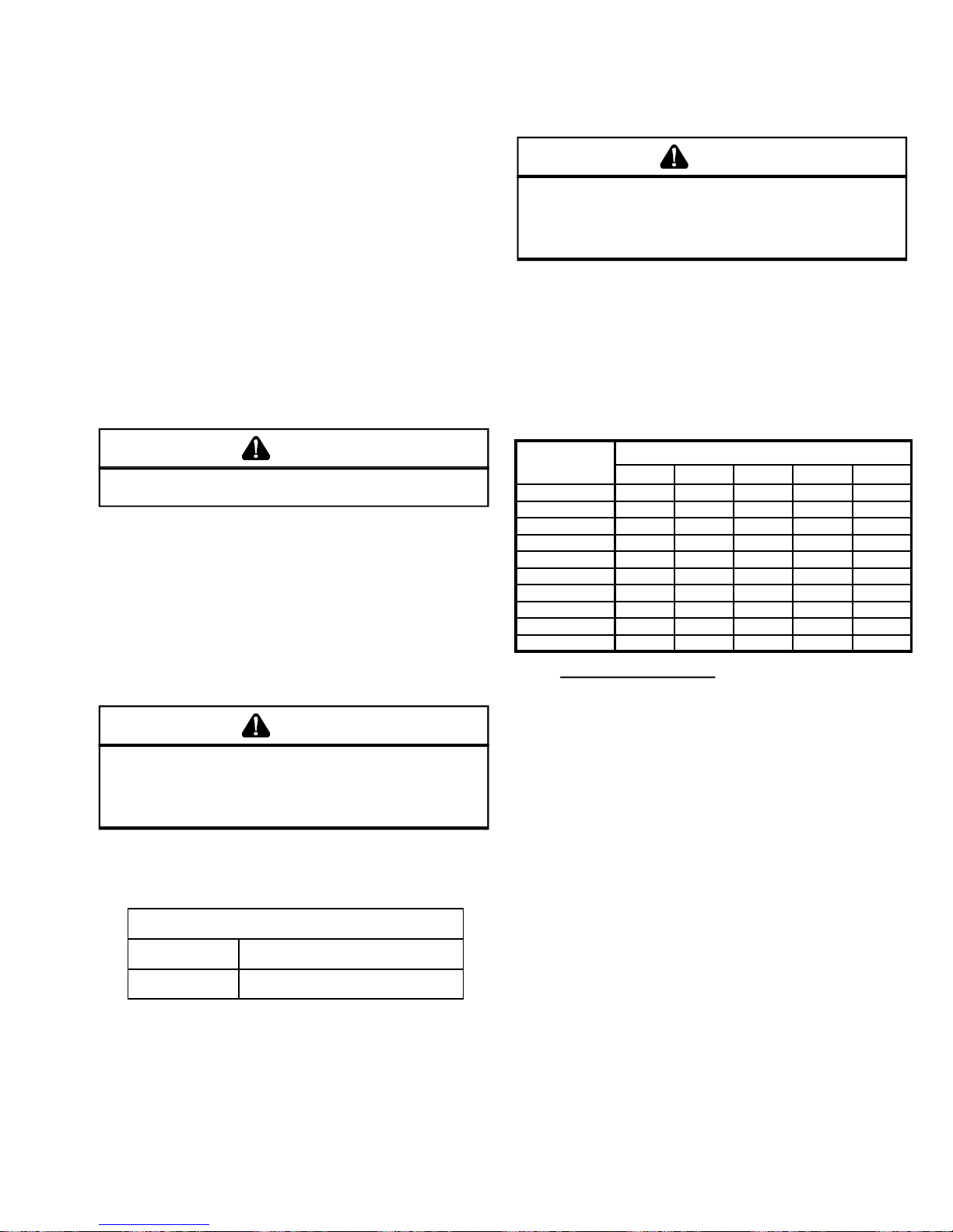
PRODUCT DESIGN
The best protection for the wiring is the smallest fuse or breaker
which will hold the equipment on line during normal operation
without nuisance trips. Such a device will provide maximum
circuit protection.
DO NOT EXCEED THE MAXIMUM OVERCURRENT DEVICE
SIZE SHOWN ON THE UNIT DATA PLATE.
All line voltage connections must be made through weather
proof fittings. All exterior power supply and ground wiring
must be in approved weather proof conduit. Low voltage wiring from the unit control panel to the thermostat requires coded
cable. Unit knock out sizes are shown in the specification
tables.
The unit transformer is connected for 230V operation. If the
unit is to operate on 208V, reconnect the transformer primary lead and the induced draft blower leads as shown on
the unit wiring diagram.
GAS PIPING
CAUTION
T
O AVOID POSSIBLE UNSATISF ACTORY OPERATION OR EQUIPMENT DAMAG E
DUE TO UNDERFIRING OF EQ UIPMENT, DO NOT UNDERSIZE THE NATURAL
GAS/PROPANE PIPING FROM THE METER/TANK TO THE FURNA CE.
SIZING A TRUNK LINE PER THE TABLES, INCLUDE ALL APPLIANCE S ON THAT
LINE THAT COULD BE OPERATED S IMULTANEOUSLY.
The gas pipe supplying the furnace must be properly sized
based on the cubic feet per hour of gas flow required, specific
gravity of the gas and length of the run. The gas line installation must comply with local codes, or in the absence of local
codes, with the latest edition of the National Fuel Gas Code
ANSI Z223.1.
NATURAL GAS CAPACITY OF PIPE IN CUBIC FEET OF
GAS PER HOUR (CFH)
WHEN
WARNING
T
O AVOID THE RISK OF FIRE, PROPER TY DAMAGE OR PER SONAL INJURY,
USE ONLY COPPER CONDUCTORS.
If it is necessary for the installer to supply additional line
voltage wiring to the inside of the package unit, the wiring
must comply with all local codes. This wiring must have a
minimum temperature rating of 105°C. and must be routed
away from the burner compartment. All line voltage splices
must be made inside the furnace junction box.
GAS SUPPLY AND PIPING
Package Gas Units
CAUTION
T
HIS PACKAGE GAS UNIT IS FACTORY SET TO OPERATE ON NATURAL
GAS AT THE ALTITUDES SHOWN ON THE RAITNG PLATE.
PROPANE IS REQUIRED, OBTAIN AND INSTALL THE PROPER CONVERSION
KIT(S) BEF ORE OPERATI NG THIS FURNA CE.
IN UNSATIS FACTORY OP ERATION AND /OR EQUIPMENT DAMAGE.
F
AILURE TO DO SO MAY RESULT
The rating plate is stamped with the model number, type of
gas, and gas input rating. Make sure the furnace is equipped
to operate on the type of gas available.
INLET GAS PRESSURE
NATURAL MIN. 5.0", MAX. 10.0"
PROPANE MIN. 11.0", MAX. 14.0 "
Inlet Gas Pressure Must Not Exceed the Maximum Value
Shown in the table Above.
The minimum supply pressure must not be varied downward
because this could lead to unreliable ignition. In addition,
gas input to the burners must not exceed the rated input
shown on the rating plate. Overfiring of the furnace could
result in premature heat exchanger failure.
I
F OPERATION ON
LENGTH OF
PIPE IN FEET
10 132 278 520 1050 1600
20 92 190 350 730 1100
30 73 152 285 590 980
40 63 130 245 500 760
50 56 115 215 440 670
60 50 105 195 400 610
70 46 96 180 370 560
80 43 90 170 350 530
90 40 84 160 320 490
100 38 79 150 305 460
CFH =
BTUH FURNACE INPUT
CALORIFIC VALUE OF GAS
NOMINAL BLACK PIPE SIZE
1/2" 3/4" 1" 1 1/4" 1 1/2"
CONNECTING THE GAS PIPING - NATURAL GAS
Refer to the figure 1 for the general layout of the furnace. The
following rules apply:
1. Use black iron or steel pipe and fittings for the building
piping.
2. Use pipe joint compound on male threads only. Pipe
joint compound must be resistant to the action of the fuel
used.
3. Use ground joint unions.
4. Install a drip leg to trap dirt and moisture before it can
enter the gas valve. The drip leg must be a minimum of
three inches long.
5. Use two pipe wrenches when making connection to the
gas valve to keep it from turning.
6. Install a manual shut off valve. This shut off valve should
be conveniently located within six (6) feet of the unit, and
between the meter and unit.
7. Tighten all joints securely.
21

PRODUCT DESIGN
8. The furnace shall be connected to the building piping by
one of the following.
a. Rigid metallic pipe and fittings.
b. Semirigid metallic tubing and metallic fittings. Alu-
minum alloy tubing shall not be used in exterior
locations.
c. Listed gas appliance connectors used in accor-
dance with the terms of their listing that are completely in the same room as the equipment.
d. In "b" and "c" above, the connector or tubing shall
be installed so as to be protected against physical and thermal damage. Aluminum-alloy tubing
and connectors shall be coated to protect against
external corrosion where they are in contact with
masonry, plaster, or insulation or are subject to
repeated wettings by such liquids as water (except rain water), detergents, or sewage.
Figure 1
CHECKING THE GAS PIPING
CAUTION
T
O AVOID THE P OSSIBILITY OF PROPERTY DAMAGE, PER SONAL INJURY OR
FIRE, THE FOLLOWING INS TRUCTIONS MUST BE PERFO RMED REGARD ING
GAS CONN ECTIONS AND PRESSURE TESTING.
The unit and its gas connections must be leak tested before
placing in operation. Because of the danger of explosion or
fire, never use a match or open flame to test for leaks. Never
exceed specified pressure for testing. Higher pressure may
damage the gas valve and cause overfiring which may result
in heat exchanger failure.
This unit and its individual shutoff valve must be disconnected
from the gas supply piping system during any pressure testing of that system at test pressures in excess of 1/2 psig
(3.48 kPa).
This unit must be isolated from the gas supply system by
closing its individual manual shutoff valve during any pressure testing of the gas supply piping system at test pressures equal to or less than 1/2 psig (3.48 kPa).
TANKS AND PIPING - PROPANE UNITS
All propane gas equipment must conform to the safety standards of the National Board of Fire Underwriters (See NBFU
Manual 58) or Natural Standards of Canada B149.2, Installation Code for Propane Gas Burning Appliances and Equipment.
For satisfactory operation, propane gas pressure must be 10
inch W.C. at the furnace manifold with all gas appliances in
operation. Maintaining proper gas pressure depends on three
main factors.
1. Vaporization rate, which depends on (a) temperature of
the liquid, and (b) "wetted surface" area of the container
or containers.
2. Proper pressure regulation. (Two-stage regulation is recommended from the standpoint of both cost and efficiency.)
3. Pressure drop in lines between regulators, and between
second stage regulator and the appliance. Pipe size required will depend on length of pipe run and total load of
all appliances.
Complete information regarding tank sizing for vaporization,
recommended regulator settings, and pipe sizing is available
from most regulator manufacturers and propane gas suppliers.
Propane is an excellent solvent, and special pipe dope must
be used when assembling piping for this gas as it will quickly
dissolve white lead or most standard commercial compounds.
Shellac base compounds resistant to the actions of liquefied
petroleum gases such as Gasolac, Stalactic, Clyde's or John
Crane are satisfactory.
Refer to Figure 2 for typical propane gas installations.
22

PRODUCT DESIGN
,
TYPICAL PROPANE PIPING
Sizing Between Single or Second Stage Regulator and Appliance
First Stage
Regulator
200 PSIG
Maximum
5 to 15 PSIG
(20 PSIG Max. )
Continuous
Second Stage
Regulator
11" W.C.
Figure 2
WARNING
I
F YOUR PROPANE GAS FURNACE IS INSTALLED IN A BASEM ENT, AN
EXCAVATED AREA OR A CONFINED SPACE, WE STRONGLY RECOMMEND
THAT YOU C ONTACT YO UR PROPAN E SUPPLIE R ABOUT INS TALLING A
WARNING DEVICE THAT WOULD ALERT YOU TO A GAS LEAK.
...... Propane gas is heavier than air and any leaking
gas can settle in any low areas or confined spaces.
...... Propane gas odorant may fade, making the gas
undetectable except with a warning device.
An undetected gas leak would create a danger of explosion or fire. If you suspect the presence of gas, follow the instructions on Page 13. Failure to do so could
result in SERIOUS PERSONAL INJURY OR DEATH.
PROPANE GAS PIPING CHARTS
Sizing Between First and Second Stage Regulator
Maximum Propane Capacities listed are based on 2 PSIG Pressure
Drop at 10 PSIG Setting. Capacities in 1000 BTU/HR
PIPE OR
TUBING
LENGTH,
To Convert to Capacities at 15 PSIG Settings -- Multiply by 1.130
To Convert to Capacities at 5 PSIG Settings -- Multiply by 0.879
TUBING SIZE, O.D., TYPE L
FEET
10 730 1700 3200 5300 8300 3200 7500
20 500 1100 2200 3700 5800 2200 4200
30 400 920 2000 2900 4700 1800 4000
40 370 850 1700 2700 4100 1600 3700
50 330 770 1500 2400 3700 1500 3400
60 300 700 1300 2200 3300 1300 3100
80 260 610 1200 1900 2900 1200 2600
100 220 540 1000 1700 2600 1000 2300
125 200 490 900 1400 2300 900 2100
150 190 430 830 1300 2100 830 1900
175 170 400 780 1200 1900 770 1700
200 160 380 730 1100 1800 720 1500
3/8" 1/2" 5/8" 3/4" 7/8" 1/2" 3/4"
NOMINAL PIPE
SCH 40
SIZE
Maximum Propane Capacities listed are based on 1/2" W.C. Pressure
Drop at 11" W.C. Setting. Capacities in 1000 BTU/HR
PIPE OR
TUBING TUBING SIZE, O.D., TYPE L NOMINAL PIPE SIZE, SCH 40
LENGTH
FEET 3/8" 1/2" 5/8" 3/4" 7/8" 1 7/8" 1/2" 3/4" 1" 1 1/4" 1 1/2"
10 39 92 199 329 501 935 275 567 1071 2205 3307
20 26 62 131 216 346 630 189 393 732 1496 2299
30 21 50 107 181 277 500 152 315 590 1212 1858
40 19 41 90 145 233 427 129 267 504 1039 1559
50 18 37 79 131 198 376 114 237 448 913 1417
60 16 35 72 121 187 340 103 217 409 834 1275
80 13 29 62 104 155 289 89 185 346 724 1086
100 11 26 55 90 138 255 78 162 307 630 976
125 10 24 48 81 122 224 69 146 275 567 866
150 9 21 43 72 109 202 63 132 252 511 787
200 8 19 39 66 100 187 54 112 209 439 665
250 8 17 36 60 93 172 48 100 185 390 590
*DATA IN ACCORDANCE WITH NFPA PAMPHLET NO. 54
PROPANE TANK SIZING (MINIMUM)
TANK SIZE REQUIRED IF LOWEST OUTDOOR
MAXIMUM GAS TEMPERATURE (AVG. FOR 24 HOURS) REACHES
NEEDED TO
VAPORIZE*
125K BTU/HR
(50 CFH)
250K BTU/HR
(100 CFH)
375K BTU/HR
(150 CFH)
500K BTU/HR
(200 CFH)
750K BTU/HR
(300 CFH)
* AVERAGE RATE/HOUR WITHDRAWL IN 8 HOUR PERIOD
32°F 20°F 10°F 0°F -10°F -20°F -30°F
115
115
115
250
250
400
GAL
250
GAL
300
GAL
400
GAL
750
GAL
GAL
250
GAL
400
GAL
500
GAL
1000
GAL
GAL
250
GAL
500
GAL
750
GAL
1500
GAL
GAL
400
GAL
500
GAL
1000
GAL
2000
GAL
GAL
500
GAL
1000
GAL
1500
GAL
2500
GAL
GAL
1000
GAL
1500
GAL
2000
GAL
4000
GAL
600
GAL
1500
GAL
2500
GAL
3500
GAL
5000
GAL
23

SYSTEM OPERA TION
SYSTEM OPERA TION
COOLING
The refrigerant used in the system is R-22. It is clear, colorless, non-toxic, non-irritating, and non-explosive liquid. The
chemical formula is CHCLF2. The boiling point, at atmospheric
pressure is -41.4°F.
A few of the important principles that make the refrigeration
cycle possible are: heat always flows from a warmer to a
cooler body, under lower pressure a refrigerant will absorb
heat and vaporize at a low temperature, the vapors may be
drawn off and condensed at a higher pressure and temperature to be used again.
The indoor evaporator coil functions to cool and dehumidify
the air through the evaporative process taking place within
the coil tubes.
NOTE: The pressures and temperatures shown are for demonstration purposes only. Actual temperatures and pressures are to be obtained from the "Cooling Performance
Chart."
High temperature, high pressure vapor leaves the compressor through the discharge line, through the reversing valve on
heat pump models, and enters the condenser coil. Air drawn
through the condenser coil by the condenser fan causes the
refrigerant to condense into a liquid by removing heat from
the refrigerant. As the refrigerant is cooled below its condensing temperature it becomes subcooled.
The subcooled high pressure liquid refrigerant now leaves the
condenser coil via the liquid line until it reaches the indoor
expansion device. (Heat pump models will also have an outdoor expansion valve/check valve assembly or a restrictor
orifice installed in the liquid line).
As the refrigerant passes through the expansion device and
into the evaporator coil a pressure drop is experienced causing the refrigerant to become a low pressure vapor. Low pressure saturated refrigerant enters the evaporator coil where
heat is absorbed from the warm air drawn across the coil by
the evaporator blower. As the refrigerant passes through the
last tubes of the evaporator coil it becomes superheated,
that is, it absorbs more heat than is necessary for the refrigerant to vaporize. Maintaining proper superheat assures that
liquid refrigerant is not returning to the compressor which
can lead to early compressor failure.
Low pressure superheated vapor leaves the evaporator coil
and returns through the suction line to the compressor where
the cycle begins again. On heat pump models the refrigerant must travel through the reversing valve and accumulator
before returning to the compressor.
HEATING - Heat Pump Models
The heating portion of the refrigeration cycle is similar to the
cooling cycle. The reversing valve reverses the flow of the
refrigerant. The indoor coil now becomes the condenser coil
and the outdoor coil becomes the evaporator coil. The reversing valve is energized in the cooling mode not in the heating
mode as some previous models were.
24
The restrictor orifice or check valve at the indoor coil will open
by the flow of refrigerant letting the now condensed liquid
refrigerant bypass the indoor expansion device. The orifice
or check valve at the outdoor coil will be forced closed by the
refrigerant flow, thereby utilizing the outdoor expansion device.
COOLING CYCLE
All Models
When the contacts of the room thermostat close making terminals R to Y & to G, on the control board. Heat pumps
thermostat make the R to O terminals also.
The control board recognizes this as a demand for cooling
and energizes the compressor contactor and indoor blower
motor. The blower delay is an integral part of the control board.
When the thermostat is satisfied, it opens its contacts, breaking the low voltage circuit, causing the compressor contactor
to open and indoor fan to stop after a 30 second delay.
If the room thermostat fan selector switch should be set to
the "on" position then the indoor blower would run continuous rather than cycling with the compressor.
HEATING CYCLE
Package Heat Pumps
When the thermostat calls for heat, making terminals R to Y,
the low voltage circuit of the transformer is completed. The
control board applies power to the contactor starting the compressor and outdoor fan motor. This also energizes the indoor blower relay (control board) through the room thermostat, starting the indoor blower motor.
When auxiliary electric heaters are used, a two stage heating single stage cooling thermostat would be installed.
Should the second stage heating contacts in the room thermostat close, which would be wired to W at the unit control
board, this would energize the coil of the electric heat relay(s).
Contacts within the relay(s) will close, bringing on the resistance heaters.
If electric heaters should be used, they may be controlled by
outdoor thermostats. (ATK01)
NOTE: Refer to the specifications section for the maximum
heaters that may be installed for a specific unit.
DEFROST CYCLE
Package Heat Pumps
The defrosting of the outdoor coil is jointly controlled by the
defrost control board, defrost (30/60) control and compressor
run time.
Solid State Timer
The defrost timer board can be connected for one of three (3)
time intervals. 30 minutes, 60 minutes, and 90 minutes (Factory connected @ 60 min.). Package heat pumps manufactured after May 1999 (9905 Serial date code) will be factory
set @ 30 min.

SYSTEM OPERA TION
Typical Package Cooling or Package Gas
Indoor
Coil
Either a thermostatic expansion valve or restrictor orifice assy
may be used depending on model, refer to the parts catalog
for the model being serviced.
Expansion Valve/Check Valve Assy in Cooling Operation
Outdoor
Coil
Thermostatic
Expansion
Valve
Chatleff
Orifice
Assy
Expansion Valve/Check Valve Assy in Heating Operation
Most expansion valves used in current Amana® brand Heat Pump products use an internally checked expansion valve. This
type of expansion valve does not require an external check valve as shown above.
Restrictor Orifice Assy in Cooling Operation Restrictor Orifice Assy in Heating Operation
In the cooling mode the orifice is pushed into its seat forcing
refrigerant to flow through the metered hole in the center of
the orifice.
In the heating mode the orifice moves back off its seat allowing refrigerant to flow unmetered around the outside of the
orifice.
25

SYSTEM OPERA TION
Typical Heat Pump System in Cooling
Reversing Valve
(Energized)
Indoor
Coil
Accumulator
Expansion device may not be as
shown. Refer to product parts
manual for actual part description.
Typical Heat Pump System in Heating
Outdoor
Coil
Thermostatic
Expansion
Valve
Check Valve
Indoor
Coil
Accumulator
Expansion device may not be as
shown. Refer to product parts
manual for actual part description.
26
Reversing Valve
(De-Energized)
Outdoor
Coil
Thermostatic
Expansion
Valve
Check Valve
 Loading...