


Amana AMH8 Installation Instructions Manual
AMH8
®
AS
-F
G
IRED
W
ARM
A
INSTALLATION INSTRUCTIONS
Installer: Affix all manuals adjacent to the unit.
These furnaces comply with requirements
embodied in the American National
Standard / National Standard of Canada
ANSI Z21.47·CSA-2.3 Gas Fired Central
Furnaces.
IR
F
URNACE
(CA TEGORY I)
®
C
US
RECOGNIZE THIS SYMBOL AS A SAFETY PRECAUTION.
ATTENTION INSTALLING PERSONNEL
As a professional installer , you have an obligation to know the product better than the customer .
This includes all safety precautions and related items.
Prior to actual installation, thoroughly familiarize yourself with this Instruction Manual.
Pay special attention to all safety warnings. Often during installation or repair , it is possible to place yourself
in a position which is more hazardous than when the unit is in operation.
Remember, it is your responsibility to inst all the product safely and to know it well enough
to be able to instruct a customer in its safe use.
Safety is a matter of common sense...a matter of thinking before acting.
Most dealers have a list of specific, good safety practices...follow them.
The precautions listed in this Installation Manual are intended as supplemental to existing practices.
However, if there is a direct conflict between existing practices and the content of this manual,
the precautions listed here take precedence.
*NOTE: Please contact your distributor or our
website for the applicable product data book
referred to in this manual.
IO-296C 08/08
is a trademark of Maytag Corporation and is used under
license to Goodman Company, L.P. All rights reserved.
www.amana-hac.com
© 2006 - 2008 Goodman Company, L.P.

Table of Contents
I. GENERAL INFORMA TION ................................................................................................................................................ 4
TO THE INSTALLER .......................................................................................................................................................... 4
TRANSPORT A TION DAMAGE .................................................................................................................................................. 4
II. SAFETY ........................................................................................................................................................................... 4
ELECTROSTATIC DISCHARGE (ESD) PRECAUTIONS ................................................................................................................. 5
III. PRODUCT APPLICA TION............................................................................................................................................... 5
IV . LOCA TION REQUIREMENTS AND CONSIDERA TIONS.................................................................................................. 6
GENERAL ....................................................................................................................................................................... 6
CLEARANCES AND ACCESSIBILITY........................................................................................................................................ 7
HORIZONT A L INSTALLATION ................................................................................................................................................. 7
FURNACE SUSPENSION ..................................................................................................................................................... 7
EXISTING FURNACE REMOVAL............................................................................................................................................. 7
THERMOST AT LOCATION ..................................................................................................................................................... 8
V . COMBUSTION AND VENTILA TION AIR REQUIREMENTS.............................................................................................. 8
VI. CA TEGORY I VENTING (VERTICAL VENTING)............................................................................................................ 10
VII. EXTERIOR MASONRY CHIMNEYS - ............................................................................................................................11
CHECKLIST SUMMARY ..................................................................................................................................................... 11
CHECK 1 - PROPER CHIMNEY TERMINATION........................................................................................................................ 12
CHECK 2 - ANY SOLID OR LIQUID FUEL APPLIANCES VENTED INTO THIS CHIMNEY CHANNEL .......................................................... 12
CHECK 3 - CHIMNEY CROWN CONDITION........................................................................................................................... 12
C
HECK 4 - DEBRIS IN CLEANOUT ..................................................................................................................................... 13
CHECK 5 - LINER CONDITION. ......................................................................................................................................... 13
CHECK 6 - DILUTION AIR............................................................................................................................................... 13
CHECK 7 - COMPLETE THE INSTALLA TION ............................................................................................................................ 13
FIX 1 - LINER TERMINA TION ............................................................................................................................................. 13
FIX 2 -CHANGE VENTING ARRANGEMENTS ............................................................................................................................ 13
FIX 3 - REBUILD THE CROWN .......................................................................................................................................... 14
FIX 4 - RELINING .......................................................................................................................................................... 14
VIII. ELECTRICAL CONNECTIONS.................................................................................................................................... 14
WIRING HARNESS ......................................................................................................................................................... 15
115 VOLT LINE CONNECTIONS ........................................................................................................................................ 15
FOSSIL FUIEL APPLICATIONS ........................................................................................................................................... 15
JUNCTION BOX RELOCATION ............................................................................................................................................ 15
24 VOLT THERMOSTAT WIRING......................................................................................................................................... 16
SETTING THE HEAT ANTICIPATOR ....................................................................................................................................... 16
115 VOLT LINE CONNECTION OF ACCESSORIES (ELECTRONIC AIR CLEANER)......................................................................... 16
24 VAC HUM ................................................................................................................................................................ 16
IX. GAS SUPPLY AND PIPING.......................................................................................................................................... 17
GENERAL ..................................................................................................................................................................... 17
HIGH ALTITUDE DERATE .................................................................................................................................................. 17
ALTERNATE HIGH ALTITUDE DERATE .................................................................................................................................. 17
FIRING RAT E ................................................................................................................................................................. 17
PROPAN E GAS CONVERSION ............................................................................................................................................ 18
GAS PIPING CONNECTIONS ............................................................................................................................................. 18
GENERAL ..................................................................................................................................................................... 18
UPFLOW INSTALLATIONS .................................................................................................................................................. 19
GAS PIPING CHECKS ..................................................................................................................................................... 19
PROPANE GAS TANKS AND PIPING .................................................................................................................................... 19
X. CIRCULATING AIR AND FILTERS................................................................................................................................. 20
FILTERS - READ THIS SECTION BEFORE INSTALLING THE RETURN AIR DUCTWORK ................................................................... 20
UPRIGHT INSTALLA TIONS .................................................................................................................................................. 21
CIRCULATION AIR FILTERS .............................................................................................................................................. 21
HORIZONT A L INSTALLATIONS ............................................................................................................................................. 21
XI. SEQUENCE OF OPERA TION........................................................................................................................................ 21
POWER UP .................................................................................................................................................................. 21
HEATING MODE ............................................................................................................................................................. 21
COOLING MODE ............................................................................................................................................................ 22
FAN ONLY .................................................................................................................................................................... 22
2
Table of Contents
XII. ST ART-UP PROCEDURE AND ADJUSTMENT ............................................................................................................ 22
FURNACE OPERATION ...................................................................................................................................................... 22
FURNACE START-UP ....................................................................................................................................................... 22
FURNACE SHUTDOWN .................................................................................................................................................... 22
GAS SUPPLY PRESSURE MEASUREMENT ............................................................................................................................ 23
WHITE-RODGERS 36G22 GAS VALVE ............................................................................................................................... 23
GAS MANIFOLD PRESSURE MEASUREMENT AND ADJUSTMENT ................................................................................................ 23
GAS INPUT RAT E MEASUREMENT (NATURAL GAS ONLY) ......................................................................................................... 24
TEMPERATURE RISE ........................................................................................................................................................ 24
CIRCULATOR BLOWER SPEED ADJUSTMENT ........................................................................................................................ 24
CIRCULATOR BLOWER FAN TIMING ADJUSTMENT ................................................................................................................. 25
XIII. OPERA TIONAL CHECKS ........................................................................................................................................... 25
BURNER FLAME ............................................................................................................................................................ 25
AUXILIARY LIMIT CONTROL .............................................................................................................................................. 25
XIV . SAFETY CIRCUIT DESCRIPTION .............................................................................................................................. 26
GENERAL ..................................................................................................................................................................... 26
INTEGRATED CONTROL MODULE ....................................................................................................................................... 26
PRIMARY LIMIT .............................................................................................................................................................. 26
AUXILIARY LIMIT ............................................................................................................................................................ 26
ROLLOUT LIMITS ........................................................................................................................................................... 26
PRESSURE SWITCHES .................................................................................................................................................... 26
FLAME SENSOR............................................................................................................................................................. 26
XV . TROUBLESHOOTING.................................................................................................................................................. 26
ELECTROSTATIC DISCHARGE (ESD) PRECAUTIONS ............................................................................................................... 26
DIAGNOSTIC CHART ........................................................................................................................................................ 26
RESETTING FROM LOCKOUT ............................................................................................................................................ 26
XVI. MAINTENANCE .......................................................................................................................................................... 27
ANNUAL INSPECTION ...................................................................................................................................................... 27
FILTERS ....................................................................................................................................................................... 27
FILTER MAINTENANCE ..................................................................................................................................................... 27
FILTER REMOVAL ........................................................................................................................................................... 27
UPRIGHT FILTER REMOVAL .............................................................................................................................................. 27
INDUCED DRAFT AND CIRCULATOR BLOWER MOTORS........................................................................................................... 27
FLAME SENSOR (QUALIFIED SERVICER ONLY) .................................................................................................................... 27
IGNITER (QUALIFIED SERVICER ONLY)...............................................................................................................................27
BURNERS .................................................................................................................................................................... 28
XVII. BEFORE LEA VING AN INST ALLA TION .................................................................................................................... 28
XVIII. REP AIR AND REPLACEMENT PARTS .................................................................................................................... 28
TROUBLESHOOTING CHART......................................................................................................................................... 29-30
WIRING DIAGRAM .......................................................................................................................................................... 31
WARNING
G
OODMAN WILL NOT BE RESPONSIBLE FOR ANY INJURY OR PROPERTY
DAMAGE ARISING FROM IMPROPER SERVI CE OR SERVICE PROCEDURES.
I
F YOU INSTALL OR PERFORM SERVICE ON THIS UNIT, YOU ASSUME
RESPONSIBILITY FOR ANY PERSONAL INJURY OR PROPERY DAM AGE WHICH
MAY RESULT.
SERVICE HEATING AND AIR CONDITIONING EQUIPMENT.
M
ANY JURISDIC TIONS REQUIRE A LICENSE TO INSTALL OR
WARNING
F THE INFORMATION IN TH ESE INSTRUCTIONS IS NO T FOLLOWED EXACTLY, A
I
FIRE OR EXPLOSION MAY RESULT CAUSING PROPERTY DAMAGE, PERSONAL
INJURY OR LOSS OF LIFE.
–
O NOT STORE OR USE GASOLINE OR OTHER FLAM MABLE VAPORS AND
D
LIQUIDS IN THE VICINITY OF THIS OR ANY OTHER APPLIANCE.
–
WHAT TO DO IF YOU SMELL GAS
•
•
PHONE IN YOUR BUILDING.
•
PHONE.
•
DEPARTMENT.
–
NSTALLATION AND SERVICE MUST BE PERFORMED BY A QUALIFIED INSTALLER,
I
SERVICE AGENCY OR THE GAS SUPPLIER.
O NOT TRY TO LIGHT ANY APPLIANCE.
D
O NOT TOUCH ANY ELECTRICAL SWITCH; DO N OT USE ANY
D
MMEDI ATE LY C ALL YOUR GAS SUP PLI ER F ROM A NEI GHB OR’S
I
OLLOW T HE GAS SUPPL IER ’S INS TRUCT IONS.
F
F YOU CAN NOT REAC H Y OUR GAS SUPP LIER , C ALL THE FIRE
I
:
3
I. GENERAL INFORMA TION
WARNING
WARNING
HOULD OVERHEATING OCCUR OR THE GAS SUPPLY FAIL TO SHUT OFF, TURN
S
OFF THE MANUAL GAS SHUTOFF VALVE EXTERNAL TO THE FURNACE BEFORE
TURNING OFF THE ELECTRICAL SUPPLY.
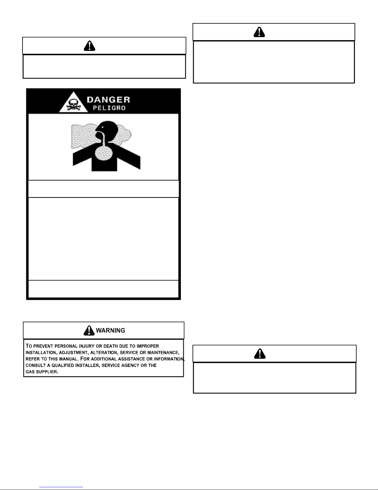
CARBON MONOXIDE POISONING HAZARD
Special Warning for Installation of Furnace or Air H andling Units in
Encl os ed Are as such as Garages, Utilit y Rooms or Parki ng Ar eas
Carbon monoxide producing devices (such as an automobile, space
heater , gas water heater, etc.) should not be operated in enclosed are a s
such as unventilated garages, utility rooms or pa rking areas because of
the danger of carbon monoxide (CO) poisoning resulting from the exhaust
emissions. If a furnace or air h an d ler is installe d in an en closed area su c h
as a garage, utility room or parking area and a carbon monoxide producing
device is operated therein, there must be adequate, direct outside
ventilation.
This ventilation is necessary to avoid the danger of CO poisoning which
can occur if a carbon monoxide producing device continues to operate in
the enclosed area. Carb o n m onoxide emissions can be (re)circ u lated
throughout the structure if the furnace or air handler is operating in any
mode.
CO can cause serious illness including permanent brain damage or death.
B10259-216
-
O PREVENT P OSSIBLE PERSONAL IN JURY OR DE ATH DUE TO ASPHYXIATIO N,
T
THIS FURNACE MUST BE
C
ATEGORY
ROVISIONS MUST BE MADE FOR VENTING COMBUSTION PRODUCTS
P
OUTDOORS THROUGH A PROPER VENTING SYSTEM.
COULD BE A LIMITING FACTOR IN LO CATING THE FURNACE.
III
VENTING.
ATEGORY I VENTED. DO NOT VENT USING
C
HE LENGTH OF FLUE PIPE
T
TRANSPORTATION DAMAGE
All units are securely packed in shipping containers tested
according to International Safe Transit Association specifications.
The carton must be checked upon arrival for external damage. If
damage is found, a request for inspection by carrier’s agent must
be made in writing immediately.
The furnace must be carefully inspected on arrival for damage
and bolts or screws which may have come loose in transit. In the
event of damage the consignee should:
1. Make a notation on delivery receipt of any visible damage
to shipment or container.
2. Notify carrier promptly and request an inspection.
3. With concealed damage, carrier must be notified as soon
as possible - preferably within five days.
4. File the claim with the following support documents within
a nine month statute of limitations.
• Original or certified copy of the Bill of Lading, or indemnity
bond.
• Original paid freight bill or indemnity in lieu thereof.
• Original or certified copy of the invoice, showing trade and
other discounts or reductions.
• Copy of the inspection report issued by carrier’s
representative at the time damage is reported to carrier.
The carrier is responsible for making prompt inspection of damage
and for a thorough investigation of each claim. The distributor or
manufacturer will not accept claims from dealers for transportation
damage.
Keep this literature in a safe place for future reference.
TO THE INSTALLER
Before installing this unit, please read this manual thoroughly to
familiarize yourself with specific items which must be adhered to,
including but not limited to: unit maximum external static pressure,
gas pressures, BTU input rating, proper electrical connections,
circulating air temperature rise, minimum or maximum CFM, and
motor speed connections, and venting. These furnaces are
designed for Category I venting only.
II. SAFETY
Adhere to the following warnings and cautions when installing,
adjusting, altering, servicing, or operating the furnace.
WARNING
HIS PRODUCT CONTAINS OR PRODUCES A CHEMICAL OR CHEMICALS WHICH
T
MAY CAUSE SERIOUS ILLNESS OR DEATH AND WHICH ARE KNOWN TO THE
S
TATE OF CALIFORNIA TO CAUSE CANCER, BIRTH DEFECTS OR OTHER
REPRODUCTIVE HARM.
4
WARNING
TO PREVENT POSSIBLE PROPERTY DAMAGE, PERSONAL INJURY OR DEATH
DUE TO ELECTRICAL SHOCK, THE FURNACE MUST BE LOCATED TO PROTECT
THE ELECTR ICAL COMPO NENTS FROM WA TER.
WARNING
EATING UNIT SHOULD NOT BE UTILIZED WITHOUT REASONABLE, ROUTINE,
H
INSPECTIO N, MAINTENANCE AND SUPERVISION.
SUCH DEVICE IS LOCATED WILL BE VACANT, CARE SHOULD BE TAKEN THAT
SUCH DEVICE IS ROUTINELY INSPECTED, MAINTAINED AND MONITORED. IN THE
EVENT THAT THE BUILDING MAYBE EXPOSED TO FREEZING TEMPERATURES
AND WILL BE VACANT, ALL WATER-BEARING PIPES SHOULD BE DRAINED, THE
BUILDING SHOULD BE PROPERLY WINTERIZED, AND THE WATER SOURCE
CLOSED. I N THE EV ENT THAT THE BUI LDING MA Y BE EX POSED TO FREEZI NG
TEMPERATURES AND WILL BE VACANT, ANY HYDRONIC COIL UNITS SHOULD
BE DRAINED AS WELL AND, IN SUCH CASE, ALTERNATIVE HEAT SOURCES
SHOULD BE UT ILIZED.
F THE BUILIDNG IN WHICH ANY
I
ADDITIONAL SAFETY C ONSIDERATIONS
• This furnace is approved for Category I Venting only.
• Provisions must be made for venting combustion products
outdoors through a proper venting system. The length of
flue pipe could be a limiting factor in locating the furnace.
ELECTROSTATIC DISCHARGE (ESD) PRECAUTIONS
NOTE: Discharge body’s static electricity before touching unit. An
electrostatic discharge can adversely affect electrical components.
Use the following precautions during furnace installation and
servicing to protect the integrated control module from damage.
By putting the furnace, the control, and the person at the same
electrostatic potential, these steps will help avoid exposing the
integrated control module to electrostatic discharge. This
procedure is applicable to both installed and non-installed
(ungrounded) furnaces.
1. Disconnect all power to the furnace. Do not touch the
integrated control module or any wire connected to the
control prior to discharging your body’s electrostatic
charge to ground.
2. Firmly touch a clean, unpainted, metal surface of the
furnaces near the control. Any tools held in a person’s
hand during grounding will be discharged.
3. Service integrated control module or connecting wiring
following the discharge process in step 2. Use caution
not to recharge your body with static electricity; (i.e., do not
move or shuffle your feet, do not touch ungrounded objects,
etc.). If you come in contact with an ungrounded object,
repeat step 2 before touching control or wires.
4. Discharge your body to ground before removing a new
control from its container. Follow steps 1 through 3 if
installing the control on a furnace. Return any old or new
controls to their containers before touching any ungrounded
object.
This furnace can be used in the following non-industrial
commercial applications:
Schools, Office buildings, Churches, Retail stores,
Nursing homes, Hotels/motels, Common or office areas
In such applications , the furnace must be installed with the
following stipulations:
• It must be installed per the installation instructions provided
and per local and national codes.
• It must be installed indoors in a building constructed on
site.
• It must be part of a ducted system and not used in a free air
delivery application.
• It must not be used as a “make-up” air unit.
• All other warranty exclusions and restrictions apply.
This furnace may be used as a construction site heater ONLY if
the following conditions are met:
• The vent system is permanently installed per these
installation instructions.
• A room thermostat is used to control the furnace. Fixed
jumpers that provide continuous heating CANNOT be used.
• Return air ducts are provided and sealed to the furnace.
• A return air temperature range between 60ºF (16ºC) and
80ºF (27ºC) is maintained.
• Air filters are installed in the system and maintained during
construction, replaced as appropriate during construction,
and upon completion of construction are replaced.
• The input rate and temperature rise are set per the furnace
rating plate.
• 100% outside air is provided for combustion air
requirements during construction. Temporary ducting can
be used.
NOTE: Do not connect the temporary duct directly to the
furnace. The duct must be sized according to the
instructions under Section V, Combustion and Ventilation
Air Requirements, Section 5.3.3.
• The furnace heat exchanger, components, duct system,
air filters and evaporator coils are thoroughly cleaned
following final construction clean up.
• All furnace operating conditions (including ignition, input
rate, temperature rise and venting) are verified according
to these installation instructions.
NOTE: The Commonwealth of Massachusetts requires that the
following additional requirements must also be met:
• Gas furnaces must be installed by a licensed plumber or
gas fitter.
• A T-handle gas cock must be used.
• If the unit is to be installed in an attic, the passageway to
and the service area around the unit must have flooring.
To ensure proper installation and operation, thoroughly read this
manual for specifics pertaining to the installation and application
of this product.
III. PRODUCT APPLICA TION
This furnace is primarily designed for residential home-heating
applications. It is NOT designed or certified for use in mobile
homes, trailers or recreational vehicles. Neither is it designed or
certified for outdoor applications. The furnace must be installed
indoors (i.e., attic space, crawl space, or garage area provided
the garage area is enclosed with an operating door).
WARNING
OSSIBLE PROPERTY DAMAGE, PERSONAL INJURY OR DEATH DUE TO FIRE,
P
EXPLOSION, SMOKE, SOOT, CONDENSTAION, ELECTRICAL SHOCK OR CARBON
MONOXIDE MAY RESULT FROM IMPROPER INSTALLATION, REPAIR, OPERATION,
OR MAINTENANCE OF THIS PRODUCT.
5
WARNING
T
O PREVENT PROPERTY DAMAGE, PERSONAL INJURY OR DEATH DUE TO FIRE,
DO NOT INSTALL THIS FURNACE IN A MOBILE HOME, TRAILER, OR RECREATIONAL
VEHICLE.
To ensure proper furnace operation, install, operate and maintain
the furnace in accordance with these installation and operation
instructions, all local building codes and ordinances. In their
absence, follow the latest edition of the National Fuel Gas Code
(NFPA 54/ANSI Z223.1), and/or CAN/CSA B149 Installation Codes,
local plumbing or waste water codes, and other applicable codes.
A copy of the National Fuel Gas Code (NFPA 54/ANSI Z223.1) can
be obtained from any of the following:
American National Standards Institute
1430 Broadway
New York, NY 10018
National Fire Protection Association
1 Batterymarch Park
Quincy, MA 02269
CSA International
8501 East Pleasant Valley
Cleveland, OH 44131
A copy of the CAN/CSA B149 Installation Codes can also be
obtained from:
CSA International
178 Rexdale Boulevard
Etobicoke, Ontario, Canada M9W 1R3
The rated heating capacity of the furnace should be greater than
or equal to the total heat loss of the area to be heated. The total
heat loss should be calculated by an approved method or in
accordance with “ASHRAE Guide” or “Manual J-Load Calculations”
published by the Air Conditioning Contractors of America.
In the USA, this furnace MUST be installed in accordance with the
latest edition of the ANSI Z223.1 booklet entitled “National Fuel
Gas Code” (NFPA 54), and the requirements or codes of the local
utility or other authority having jurisdiction. In Canada, this furnace
must be installed in accordance with the current CAN/CGA-B149.1
& 2 Gas Installation Codes, local plumbing or waste water codes
and other applicable codes. Additional helpful publications
available from the NFPA are, NFPA 90A - Installation of Air
Conditioning and Ventilating System and NFPA 90B - Warm Air
Heating and Air Conditioning System.
All venting shall be in accordance with PART 7, Venting of
Equipment, of the National Fuel Gas Code, ANSI Z223.1, or
applicable local building and/or air conditioning codes. These
publications are available from:
National Fire Protection Association, Inc.
Batterymarch Park, Quincy, MA 02269
The AMH8 furnaces meet the California NOx emission standards
and California seasonal efficiency standards. ANNUAL
inspections of the furnace and its vent system is strongly
recommended.
IV . LOCA TION REQUIREMENTS AND CONSIDERA TIONS
GENERAL
Model type determines which installation procedures must be
used. For AMH8 models, you must follow instructions for Horizont al
Left, Horizontal Right or Upflow installations only. AMH8 models
are not approved for Downflow installations.
WARNING
OSSIBLE PROPERTY DA MAGE, PERSONAL INJUR Y OR DEATH DUE TO FIRE ,
P
EXPLOSION, SMOKE, SOO T, CONDENSTAION, ELECTRICAL SHOCK OR CARBON
MONOXIDE MAY RESULT FROM I MPROP ER INSTA LLATIO N, RE PAIR, OP ERATIO N,
OR MAINTENANCE OF TH IS PRODUCT.
WARNING
O PREVENT POSSIBLE EQUIPMENT DAMAGE, PROPERTY DAMAGE, PERSONAL
T
INJURY OR DEATH, THE FOLLOWING BULLET POINTS MUST BE OBSERVED
WHEN INSTALLING THE UNIT.
Follow the instructions listed below when selecting a furnace
location. Refer also to the guidelines provided in Section V,
Combustion and Ventilation Air Requirements.
• Centrally locate the furnace with respect to the proposed
or existing air distribution system.
• Ensure the temperature of the return air entering the
furnace is between 55°F and 100°F when the furnace is
heating.
• Provisions must be made for venting combustion products
outdoors through a proper venting system. The length of
flue pipe could be a limiting factor in locating the furnace.
• Ensure adequate combustion air is available for the
furnace. Improper or insufficient combustion air can
expose building occupants to gas combustion products
that could include carbon monoxide. Refer to Section V,
Combustion and Ventilation Air Requirements.
• The furnace must be level. If the furnace is to be set on a
floor that may become wet or damp at times, the furnace
should be supported above the floor on a concrete base
sized approximately 1-1/2" larger than the base of the
furnace.
• Ensure upflow or horizontal furnaces are not installed
directly on carpeting, or any other combustible material.
The only combustible material allowed is wood.
• Exposure to contaminated combustion air will result in
safety and performance-related problems. Do not install
the furnace where the combustion air is exposed to the
following substances:
chlorinated waxes or cleaners
chlorine-based swimming pool chemicals
water softening chemicals
deicing salts or chemicals
carbon tetrachloride
halogen type refrigerants
cleaning solutions (such as perchloroethylene)
printing inks
paint removers
varnishes
hydrochloric acid
cements and glues
antistatic fabric softeners for clothes dryers
and masonry acid washing materials
• If the furnace is used in connection with a cooling unit,
install the furnace upstream or in parallel with the cooling
unit coil. Premature heat exchanger failure will result if the
cooling unit coil is placed ahead of the furnace.
• If the furnace is installed in a residential garage, position
the furnace so that the burners and ignition source are
located not less than 18 inches (457 mm) above the floor.
Protect the furnace from physical damage by vehicles.
6
• If the furnace is installed horizontally, the furnace access
V
doors must be vertical so that the burners fire horizontally
into the heat exchanger. Do not install the unit with the
access doors on the “up/top” or “down/bottom” side of the
furnace.
• Do not connect this furnace to a chimney flue that serves a
separate appliance designed to burn solid fuel.
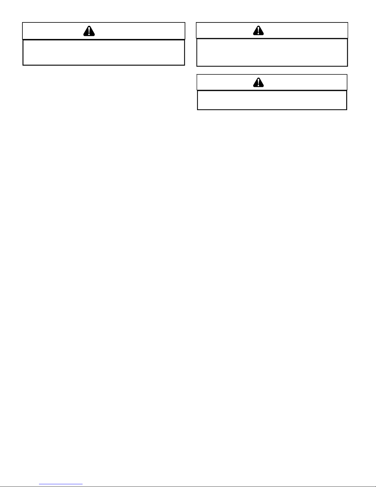
ent Pipe Cleara nc e to Com b us tib l e s6" using Single Wall Connector or 1"
using B-1 vent.
3/8" DIAMETER
THREADED ROD
(6 PLACES)
HOLD DOWN
NUTS
SUPPORT
NUTS
PROVIDE 8" MINMUM CLEARANCE BETWEEN
CENTER ROD AND FURNACE CABINET
TO ALLOW FOR CIRCULATOR BLOWER REMOVAL
ASSURE FU RNACE IS LEV EL FROM
END TO END AND HAS A SLIGHT
FORWARD T ILT WI TH THE FRONT
OF THE FURNACE 0"-3/4"
BELOW THE BA CK O F TH E F URNACE
Top - 1"
Back - 0"
Side
Clearance - 1"
2" X 2" X 3/8"
A
NGLE IRON
(3 PLACES)
POSITION AS CLOSE AS POSSIBLE
TO BLOWER DECK TO ALLOW FOR
CIRCULATOR BLOWER REMVOAL
Suspended Furnace
TILT OUTWARD TO ALLOW FOR
DOOR AND CIRCULATOR BLOWER
REMOVAL
EXISTING FURNACE REMOVAL
NOTE: When an existing furnace is removed from a venting system
serving other appliances, the venting system may be too large to
properly vent the remaining attached appliances.
The following vent testing procedure is reproduced from the
American National Standard/National Standard of Canada for
Front Clearance - 3"
• Adequate combustion/ventilation air must be supplied to
the closet.
• Furnace must be completely sealed to floor or base.
Combustion/ ventilation air supply pipes must terminate
12" from top of closet and 12" from floor of closet. DO NOT
remove solid base plate for side return.
• Return air ducts must be completely sealed to the furnace
and terminate outside the enclosure surfaces.
CLEARANCES AND ACCESSIBILITY
Unobstructed front clearance of 24" for servicing is
recommended.
VENT
B1-VENT SINGLE
1" 6" 1" 3" 0" 1"
SIDES FRONT BACK
TOP
(PLEN U M )
Top clearance for horizontal configuration - 1"
HORIZONTAL INSTALLATION
Line contact to framing is permitted when installed in the horizontal
configuration. Line contact is defined as the portion of the cabinet
that is formed by the intersection of the top and side.
ACCESSIBILITY CLEARANCE,WHERE GREA TER, SHOULD T AKE
PRECEDENCE OVER MINIMUM FIRE PROTECTION
CLEARANCE. A gas-fired furnace for installation in a residential
garage must be installed so that the ignition source and burners
are located not less than eighteen inches (18") above the floor
and is protected or located to prevent physical damage by vehicles.
A gas furnace must not be installed directly on carpeting, tile, or
other combustible materials other than wood flooring.
FURNACE SUSPENSION
If suspending the furnace from rafters or joist, use 3/8" threaded
rod and 2”x2”x3/8” angle iron as shown below. The length of rod
will depend on the application and the clearances necessary.
Gas-Fired Central Furnaces ANSI Z21.47-Latest Edition, CSA-
2.3-Latest Edition Section 1.23.1. The following steps shall be
followed with each appliance connected to the venting system
placed in operation, while any other appliances connected to the
venting system are not in operation:
a. Seal any unused openings in the venting system;
b. Inspect the venting system for proper size and horizontal
pitch, as required by the National Fuel Gas Code, ANSI
Z223.1 or the CAN/CSA B149 Installation Codes and these
instructions. Determine that there is no blockage or
restriction, leakage, corrosion and other deficiencies which
could cause an unsafe condition;
c.In so far as practical, close all building doors and windows
and all doors between the space in which the appliance(s)
connected to the venting system are located and other
spaces of the building. Turn on clothes dryers and any
appliance not connected to the venting system. Turn on
any exhaust fans, such as range hoods and bathroom
exhausts, so they shall operate at maximum speed. Do
not operate a summer exhaust fan. Close fireplace
dampers;
d. Follow the lighting instructions. Place the appliance being
inspected in operation. Adjust thermostat so appliance
shall operate continuously;
e.Test for draft hood equipped appliance spillage at the draft
hood relief opening after 5 minutes of main burner
operation. Use the flame of a match or candle;
f. After it has been determined that each appliance connected
to the venting system properly vents when tested as
outlined above, return doors, windows, exhaust fans,
fireplace dampers and any other gas burning appliance to
their previous conditions of use;
g. If improper venting is observed during any of the above
tests, the common venting system must be corrected.
Corrections must be in accordance with the latest edition of the
National Fuel Gas Code NFPA 54/ANSI Z223.1 and/or CAN/CSA
B149 Installation Codes.
7
If resizing is required on any portion of the venting system, use the
appropriate table in Appendix G in the latest edition of the National
Fuel Gas Code ANSI Z223.1 and/or CAN/CSA B149 Installation
Codes.
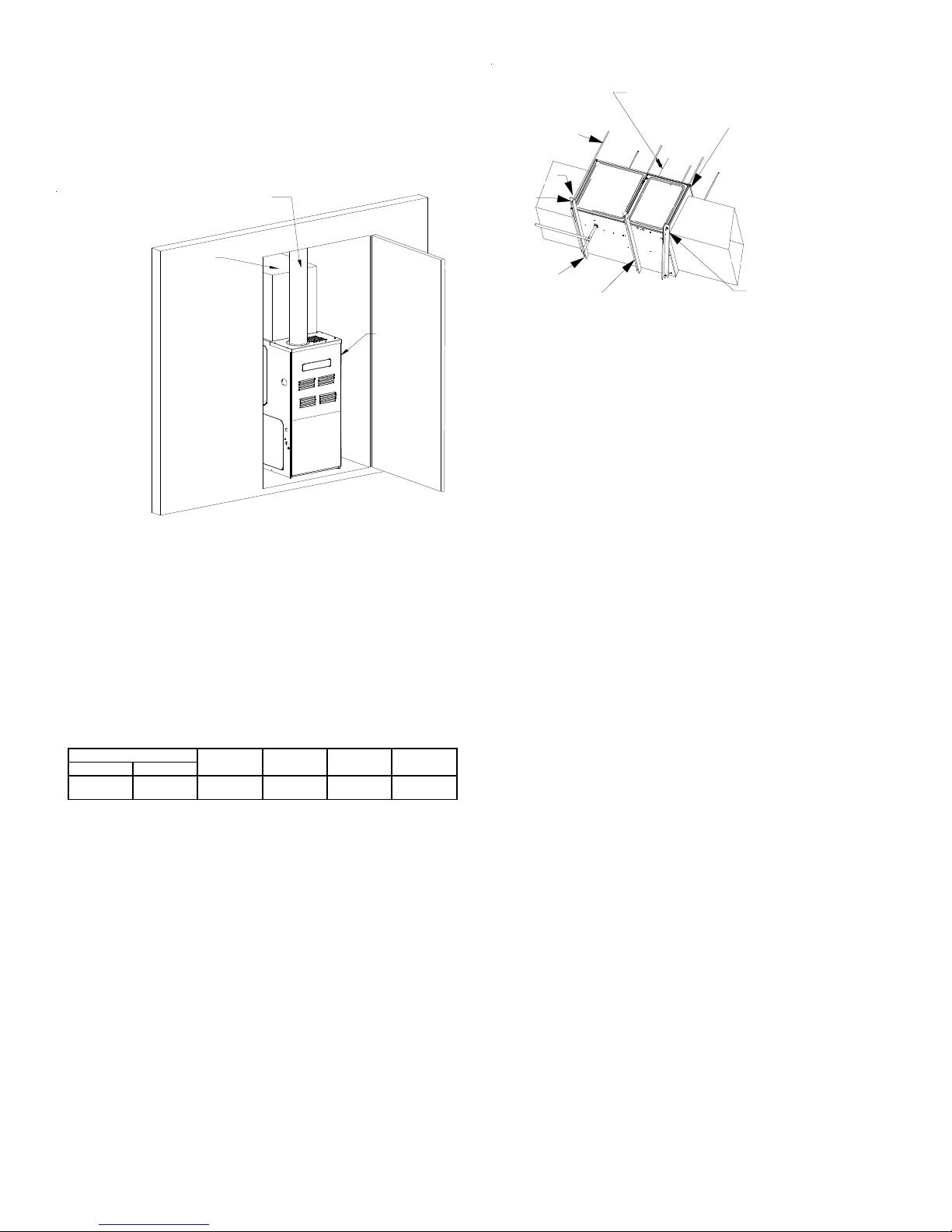
THERMOSTAT LOCATION
In an area having good air circulation, locate the thermostat about
five feet high on a vibration-free inside wall. Do not install the
thermostat where it may be influenced by any of the following:
• Drafts, or dead spots behind doors, in corners, or under
cabinets.
• Hot or cold air from registers.
• Radiant heat from the sun.
• Light fixtures or other appliances.
• Radiant heat from a fireplace.
• Concealed hot or cold water pipes, or chimneys.
• Unconditioned areas behind the thermostat, such as an
outside wall.
DRAFTS OR DEAD SPOTS
-BEHIND DOORS
-IN CORNERS
-UNDER CABINETS
Thermostat Influences
Consult the instructions packaged with the thermostat for mounting
instructions and further precautions.
V . COMBUSTION AND VENTILA TION AIR REQUIREMENTS
WARNING
O AVOID PROPERTY DAMAGE, PERSONAL INJURY OR DEATH, SUFFICIENT
T
FRESH AIR FO R PROPER COMBUSTION AND VENTILATION OF FLUE GASES MUST
BE SUPPL IE D.
FURNACE AREA.
Improved construction and additional insulation in buildings have
reduced heat loss by reducing air infiltration and escape around
doors and windows. These changes have helped in reducing
heating/cooling costs but have created a problem supplying
combustion and ventilation air for gas fired and other fuel burning
appliances. Appliances that pull air out of the house (clothes
dryers, exhaust fans, fireplaces, etc.) increase the problem by
starving appliances for air.
House depressurization can cause back drafting or improper
combustion of gas-fired appliances, thereby exposing building
occupants to gas combustion products that could include carbon
monoxide.
OST HOMES REQUIRE OUTSIDE AIR BE SUPPLIED INTO THE
M
HOT
COLD
If this furnace is to be installed in the same space with other gas
appliances, such as a water heater, ensure there is an adequate
supply of combustion and ventilation air for the other appliances.
Refer to the latest edition of the National Fuel Gas Code NFP A 54/
ANSI Z223.1 (Section 5.3), or CAN/CSA B149 Installation Codes
(Sections 7.2, 7.3, or 7.4), or applicable provisions of the local
building codes for determining the combustion air requirements
for the appliances.
This furnace must use indoor air for combustion. It cannot be
installed as a direct vent (i.e., sealed combustion) furnace.
Most homes will require outside air be supplied to the furnace
area by means of ventilation grilles or ducts connecting directly to
the outdoors or spaces open to the outdoors such as attics or
crawl spaces.
The following information on air for combustion and ventilation is
reproduced from the National Fuel Gas Code NFPA 54/ANSI
Z223.1 Section 5.3.
5.3.1 General:
(a) The provisions of 5.3 apply to gas utilization equipment
installed in buildings and which require air for combustion,
ventilation and dilution of flue gases from within the building.
They do not apply to (1) direct vent equipment which is
constructed and installed so that all air for combustion is
obtained from the outside atmosphere and all flue gases
are discharged to the outside atmosphere, or (2) enclosed
furnaces which incorporate an integral total enclosure and
use only outside air for combustion and dilution of flue
gases.
(b) Equipment shall be installed in a location in which the
facilities for ventilation permit satisfactory combustion of
gas, proper venting and the maintenance of ambient
temperature at safe limits under normal conditions of use.
Equipment shall be located so as not to interfere with
proper circulation of air. When normal infiltration does not
provide the necessary air, outside air shall be introduced.
(c) In addition to air needed for combustion, process air shall
be provided as required for: cooling of equipment or
material, controlling dew point, heating, drying, oxidation
or dilution, safety exhaust, odor control, and air for
compressors.
(d) In addition to air needed for combustion, air shall be
supplied for ventilation, including all air required for comfort
and proper working conditions for personnel.
(e) While all forms of building construction cannot be covered
in detail, air for combustion, ventilation and dilution of flue
gases for gas utilization equipment vented by natural draft
normally may be obtained by application of one of the
methods covered in 5.3.3 and 5.3.4.
(f) Air requirements for the operation of exhaust fans, kitchen
ventilation systems, clothes dryers, and fireplaces shall
be considered in determining the adequacy of a space to
provide combustion air requirements.
5.3.2 Equipment Located in Unconfined Spaces:
In unconfined spaces (see definition below) in buildings,
infiltration may be adequate to provide air for combustion
ventilation and dilution of flue gases. However, in buildings
of tight construction (for example, weather stripping, heavily
insulated, caulked, vapor barrier, etc.), additional air may
need to be provided using the methods described in 5.3.3b or 5.3.4.
8
Space, Unconfined.
A
For purposes of this Code, a space whose volume is not
less than 50 cubic feet per 1,000 BTU per hour of the
aggregate input rating of all appliances installed in that
space. Rooms communicating directly with the space in
which the appliances are installed through openings not
furnished with doors, are considered a part of the
unconfined space.
5.3.3 Equipment Located in Confined Spaces:
(a) All Air from Inside the Building: The confined space shall
be provided with two permanent openings communicating
directly with an additional room(s) of sufficient volume so
that the combined volume of all spaces meets the criteria
for an unconfined space. The total input of all gas utilization
equipment installed in the combined space shall be
considered in making this determination. Each opening
shall have a minimum free area of 1 square inch per 1,000
BTU per hour of the total input rating of all gas utilization
equipment in the confined space, but not less than 100
square inches. One opening shall be within 12 inches of
the top and one within 12 inches of the bottom of the
enclosure.
NOTE: Each opening must have
a free area of not less tha n on e
square inch per 1000 BTU of
the total input rating of all equipment in the enclosure, bu t not
less than 100 square inches.
Chimney or Gas Vent
Water
Heater
Furnace
Opening
lternate
air inlet
Chimney or Gas Vent
Water
Heater
Furnace
Ventilation louvers for
unheated crawl space
Ventilation louvers
(each end of attic)
Outlet Air
Inlet Air
NOTE: The inlet and outlet air
openings must each have a free
area of not less tha n one square
inch per 4000 BTU of the
total input rating of all equipment
in the enclosure.
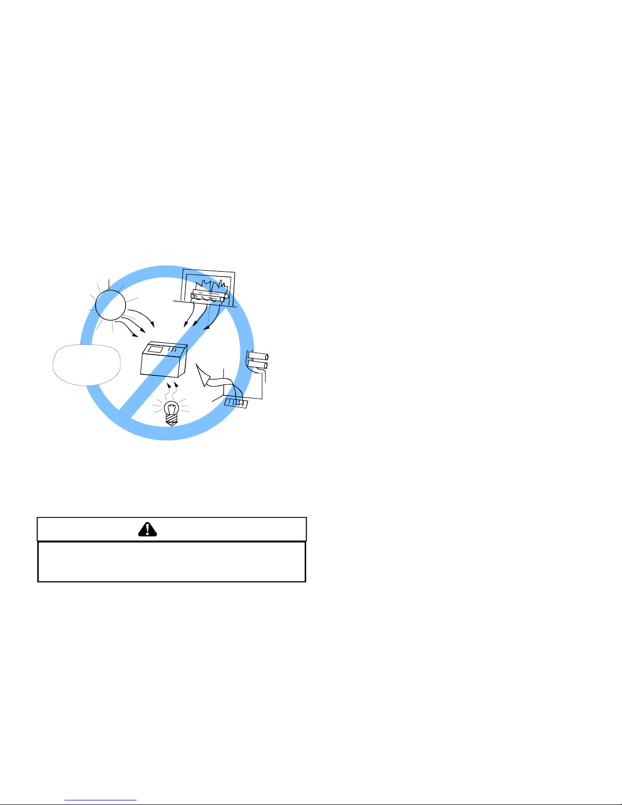
Equipment Located in Confined Spaces; All Air from Outdoors—
Inlet Air from Ventilated Crawl Space and Outlet Air to Ventilated
Attic. See 5.3.3-b
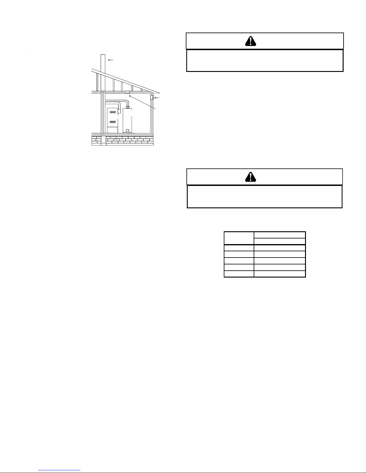
2. When communicating with the outdoors through vertical
ducts, each opening shall have a minimum free area of
1 square inch per 4,000 BTU per hour of total input
rating of all equipment in the enclosure.
Chimney or Gas Vent
Water
Heater
Furnace
Ventilation louvers
(each end of attic)
Outlet Air
Inlet air duct
[ends 1 ft (300 mm)
above floor]
NOTE: The inlet and outlet air
openings must each have a free
area of not less than one square
inch per 4000 B TU of the
total input rating of all equipment
in the enclosure.
Opening
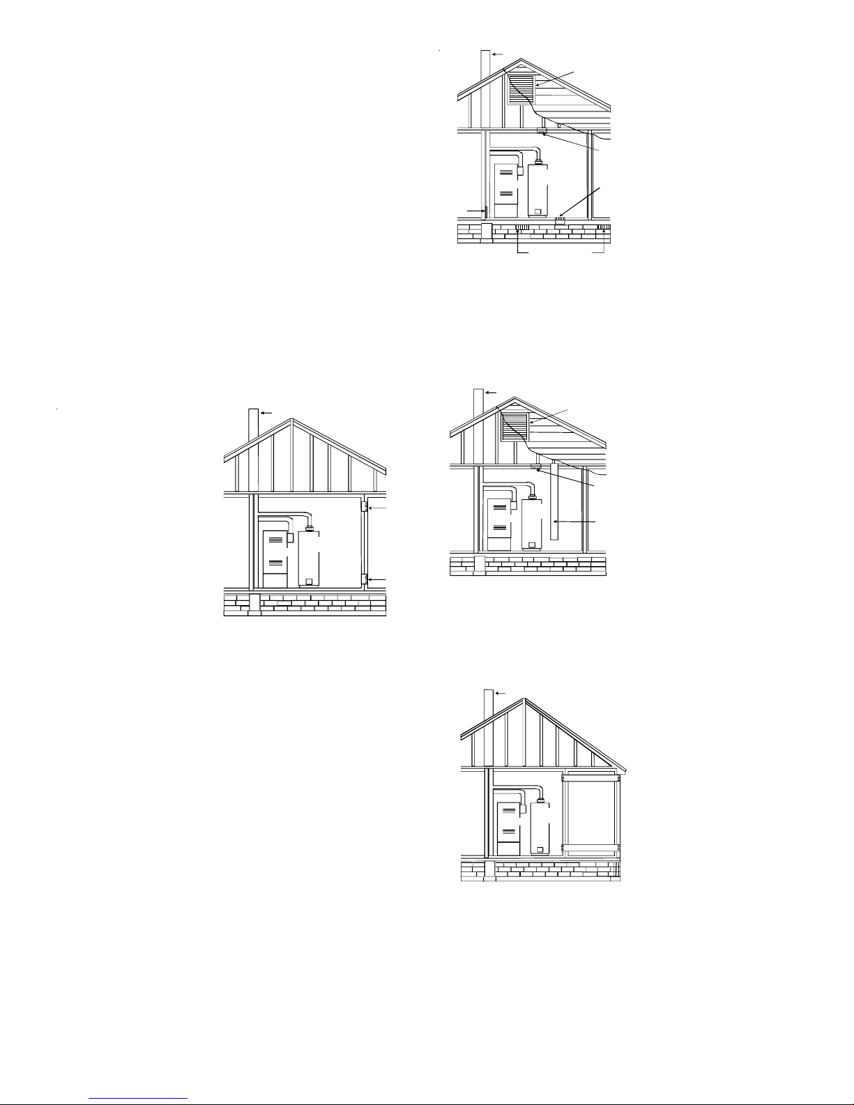
Equipment Located in Confined Spaces;
All Air from Inside Building. See 5.3.3-a.
(b) All Air from Outdoors: The confined space shall be provided
with two permanent openings, one commencing within 12
inches of the top and one commencing within 12 inches of
the bottom of the enclosure. The openings shall
communicate directly, or by ducts, with the outdoors or
spaces (crawl or attic) that freely communicate with the
outdoors.
1. When directly communicating with the outdoors, each
opening shall have a minimum free area of 1 square
inch per 4,000 BTU per hour of total input rating of all
equipment in the enclosure.
Equipment Located in Confined Spaces; All Air from Outdoors
Through Ventilated Attic. See 5.3.3-b.
3. When communicating with the outdoors through
horizontal ducts, each opening shall have a minimum
free area of 1 square inch per 2,000 BTU per hour of
total input rating of all equipment in the enclosure.
Chimney or Gas Vent
NOTE: The air duct openings
must have a free area of not
less than one square inch per
2000 BTU of the total input
Outlet air duct
Water
Heater
Furnace
Inlet air duct
Equipment Located in Confined Spaces; All Air from Outdoors -
See 5.3.3-b.
rating of all equipment in the
enclosure*.
*If the appliance room is located against an outside wall and the
air openings communicate directly with the outdoors, each opening
shall have a free area of not less than one square inch per 4,000
BTU per hour of the total input rating of all appliances in the
enclosure.
9
4. When ducts are used, they shall be of the same crosssectional area as the free area of the openings to which
they connect. The minimum dimension of rectangular
air ducts shall not be less than 3 inches.
NOTE: The single opening must have
a free area of not less than one
square inch per 3000 BTU of
the total input rating of all equipment in the enclosure, but not less than
the sum of the ar eas of all vent
connectors in the confined space.
Equipment Located in Confined Spaces; All Air from Outdoors.
Single Air Opening. See 5.3.3-b.
Chimney o r Gas Vent
Water
Heater
Furnace
Opening
Alternate
Opening
Location
5. One permanent opening may be permitted, provided the
equipment has clearances of at least 1” from the sides
and back and 6” from the front. The opening shall
communicate directly with the outdoors and must be
located within 12” of the top of the enclosure. The
minimum free area of the opening shall be 1 square
inch per 3,000 BTU per hour of total input rating of all
equipment in the enclosure. The minimum free area
shall not be less than the sum of the areas of all vent
connectors in the confined space.
VI. CA TEGORY I VENTING (VERTICAL VENTING)
WARNING
O PREVENT POSSIBLE PERSONAL INJURY OR DEATH DUE TO ASPHYXIATION,
T
THIS FURNACE MUST BE
C
ATEGORY
III
VENT ING.
ATEGORY I VENTED. DO NOT VENT USING
C
Category I Venting is venting at a non-positive pressure. A furnace
vented as Category I is considered a fan-assisted appliance and
the vent system does not have to be “gas tight.” NOTE: Single
stage gas furnaces with induced draft blowers draw products of
combustion through a heat exchanger allowing, in some instances,
common venting with natural draft appliances (i.e. water heaters).
All installations must be vented in accordance with National Fuel
Gas Code NFPA 54/ANSI Z223.1 - latest edition. In Canada, the
furnaces must be vented in accordance with the National Standard
of Canada, CAN/CSA B149.1 and CAN/CSA B149.2 - latest editions
and amendments.
NOTE: The vertical height of the Category I venting system must
be at least as great as the horizontal length of the venting system.
WARNING
O PREVENT POSSIBL E PERSONAL INJURY OR DEATH DUE TO ASPHYXIATION,
T
COMMON VENTING WITH OTHER MANUFACTURER'S INDUCED DRAFT APPLIANCS
IS NOT ALLOWED.
The minimum vent diameter for the Category I venting system is
as shown:
5.3.4 Specially Engineered Installations:
The requirements of 5.3.3 shall not necessarily govern when
special engineering, approved by the authority having
jurisdiction, provides an adequate supply of air for combustion,
ventilation, and dilution of flue gases.
5.3.5 Louvers and Grilles:
In calculating free area in 5.3.3, consideration shall be given
to the blocking effect of louvers, grilles or screens protecting
openings. Screens used shall not be smaller than 1/4 inch
mesh. If the area through a design of louver or grille is known,
it should be used in calculating the size of opening required
to provide the free area specified. If the design and free area
is not known, it may be assumed that wood louvers will have
20-25 percent free area and metal louvers and grilles will
have 60-75 percent free area. Louvers and grilles shall be
fixed in the open position or interlocked with the equipment
so that they are opened automatically during equipment
operation.
5.3.6 Special Conditions Created by Mechanical Exhausting or
Fireplaces:
Operation of exhaust fans, ventilation systems, clothes dryers,
or fireplaces may create conditions requiring special attention
to avoid unsatisfactory operation of installed gas utilization
equipment.
MODEL
45 4 Inch
70 4 Inch
90 4 Inch
115 5 Inch
140 5 Inch
MINIMUM VENT
UPFLOW
Under some conditions, larger vents than those shown above
may be required or allowed. When an existing furnace is removed
from a venting system serving other appliances, the venting system
may be too large to properly vent the remaining attached
appliances.
Upflow or Horizontal units are shipped with the induced draft
blower discharging from the top of the furnace. (“Top” is as viewed
for an upflow installation.) The induced draft blower can be rotated
90 degrees for Category I venting. For horizontal installations, a
four inch single wall pipe can be used to extend the induced draft
blower outlet 1/2” beyond the furnace cabinet. Vent the furnace in
accordance with the National Fuel Gas Code NFP A 54/ANSI Z223.1
- latest edition. In Canada, vent the furnace in accordance with
the National Standard of Canada, CAN/CSA B149.1 and CAN/CSA
B149.2 - latest editions and amendments.
Venting
THIS FURNACE IS NOT DESIGN CERTIFIED TO BE
HORIZONT ALLY VENTED.
10
 Loading...