

Page 1

High-Speed Development Kit,
Stratix GX Edition
User Guide
101 Innovation Drive
San Jose, CA 95134
(408) 544-7000
http://www.altera.com
UG-STRATIXGX-1.0
P25-09565-00
Document Version: 1.0
Page 2

Copyright © 2003 Altera Corporation. All rights reserved. Altera, The Programmable Solutions Company, the stylized Altera logo, specific device designations, and all other words and logos that are identified as trademarks and/or service marks are, unless noted otherwise, the trademarks and
service marks of Altera Corporation in the U.S. and other countries. All other product or service names are the property of their respective holders. Altera products are protected under numerous U.S. and foreign patents and pending applications, maskwork rights, and copyrights. Altera warrants
performance of its semiconductor products to current specifications in accordance with Altera's standard warranty, but reserves the right to make
changes to any products and services at any time without notice. Altera assumes no responsibility or liability arising out of the application or use of any information, product, or service described herein except as expressly agreed to in writing by Altera
Corporation. Altera customers are advised to obtain the latest version of device specifications before relying on any published information and before placing orders for products or services.
Printed on recycled paper
ii Altera Corporation
Page 3

Contents
About this User Guide ............................................................................ vii
How to Find Information ...................................................................................................................... vii
How to Contact Altera ........................................................................................................................... vii
Typographic Conventions .................................................................................................................... viii
Section I. Introduction
Revision History ....................................................................................................................... Section I–i
Chapter 1. About this Kit
General Description ............................................................................................................................... 1–1
Features ................................................................................................................................................... 1–2
Documentation ....................................................................................................................................... 1–3
Section II. Getting Started
Revision History ...................................................................................................................... Section II–i
Chapter 2. Before You Begin
Development Kit Contents ................................................................................................................... 2–1
Inspect the Board ................................................................................................................................... 2–2
Software Requirements ......................................................................................................................... 2–2
Set Up Licensing .................................................................................................................................... 2–4
Next Steps ............................................................................................................................................... 2–4
Chapter 3. Board Setup
Required Hardware ............................................................................................................................... 3–3
Power Up the Board & View the XCVR Eye ..................................................................................... 3–3
Chapter 4. Run the Preloaded Diagnostic Tests
User I/O .................................................................................................................................................. 4–1
Required Hardware ......................................................................................................................... 4–2
Test Setup .......................................................................................................................................... 4–2
Run the User I/O Test ..................................................................................................................... 4–3
Stratix GX DDR SDRAM Interface ...................................................................................................... 4–5
Required Hardware & Software .................................................................................................... 4–5
Test Setup .......................................................................................................................................... 4–6
Run the Stratix GX DDR SDRAM Interface Test ......................................................................... 4–6
Altera Corporation iii
Page 4

Contents High-Speed Development Kit, Stratix GX Edition User Guide
Stratix GX HM-Zd SPI-4.2 Loopback .................................................................................................. 4–8
Required Hardware ......................................................................................................................... 4–8
Test Setup .......................................................................................................................................... 4–8
Run the Stratix GX HM-Zd SPI-4.2 Loopback Test ..................................................................... 4–9
Stratix GX HM-Zd XCVR Loopback ................................................................................................. 4–10
Required Hardware ....................................................................................................................... 4–10
Test Setup ........................................................................................................................................ 4–10
Run the Stratix GX HM-Zd XCVR Loopback Test .................................................................... 4–11
Stratix GX SFP XCVR Loopback ........................................................................................................ 4–12
Required Hardware & Software .................................................................................................. 4–12
Test Setup ........................................................................................................................................ 4–12
Run the Stratix GX SFP XCVR Loopback Test ........................................................................... 4–13
Stratix GX XCVR Eye Diagram .......................................................................................................... 4–14
Section III. Diagnostic Tests
Revision History ..................................................................................................................... Section III–i
Chapter 5. Perform the Production Diagnostic Tests
Required Hardware & Software .......................................................................................................... 5–1
Set Up the Board .................................................................................................................................... 5–1
Perform the Standard Tests ................................................................................................................ 5–10
User I/O ........................................................................................................................................... 5–10
Stratix GX-to-Stratix Bridge .......................................................................................................... 5–12
Source Synchronous HM-Zd Interface (Stratix GX HM-Zd SPI 4.2) ...................................... 5–14
Source Synchronous DPA SMA interface (Stratix GX SMA DPA) ......................................... 5–15
Gigabit Transceivers with SMA Interface (Stratix GX SMA XCVR) ....................................... 5–17
Gigabit Transceivers with HM-Zd Interface (Stratix GX HM-Zd XCVR) .............................. 5–18
Gigabit Transceivers with SFP Interface (Stratix GX SFP XCVR) ........................................... 5–19
Gigabit Transceivers with XPAK Interface (Stratix GX XPAK XCVR) ................................... 5–20
Gigabit Transceivers with HSSDC2 Interface (Stratix GX HSSDC2 XCVR) (GX40 Device Only)
............................................................................................................................................................5–21
Nios-Based Tests .................................................................................................................................. 5–22
DDR Interface (Stratix GX Nios DDR) ........................................................................................ 5–22
PMC Card Interface (Stratix Nios PMC) ..................................................................................... 5–23
Ethernet, On-Board Flash & EPC16 Flash Interface (Stratix Nios Ethernet) (Stratix Nios On-
Board Flash) (Stratix Nios EPC16 Flash) ..................................................................................... 5–25
10/100 Ethernet Network-Interface Card I/O Interface (Stratix Nios PROTO1 IO) ........... 5–29
Compact Flash Interface (Stratix Nios Compact Flash) ............................................................ 5–32
Finishing Test & Breakdown .............................................................................................................. 5–35
Chapter 6. Troubleshooting
Chapter 7. Diagnostic Test Details
Standard Tests ........................................................................................................................................ 7–1
User I/O ............................................................................................................................................. 7–1
iv Altera Corporation
Page 5

Contents Contents
Mictor & 20-Pin Header Logic Analyzer Interfaces .................................................................... 7–4
Stratix GX-to-Stratix Bridge ............................................................................................................ 7–6
Stratix GX HM-Zd (SPI-4.2) .......................................................................................................... 7–12
Stratix GX SMA DPA ..................................................................................................................... 7–15
Stratix GX SMA XCVR .................................................................................................................. 7–19
Stratix GX HM-Zd XCVR .............................................................................................................. 7–23
Stratix GX SFP XCVR ..................................................................................................................... 7–26
Stratix GX XPAK XCVR ................................................................................................................ 7–29
Stratix GX HSSDC2 XCVR ............................................................................................................ 7–32
Nios Designs ......................................................................................................................................... 7–35
Stratix GX Nios DDR Test ............................................................................................................. 7–36
Stratix Nios PMC Test ................................................................................................................... 7–38
Stratix Nios Ethernet, On-Board Flash & EPC16 Flash Test .................................................... 7–39
Stratix Nios 10/100 Ethernet Network-Interface Card I/O Test ............................................. 7–41
Stratix Nios Compact Flash Test .................................................................................................. 7–43
Section IV.
Demonstrations
Revision History ..................................................................................................................... Section IV–i
Chapter 8. Stratix GX SPI-4.2 Demonstration with 10-Port Gigabit Ethernet MAC
Chapter 9. 10-Gigabit Ethernet MAC Demonstration
Introduction ............................................................................................................................................ 9–1
Contact .................................................................................................................................................... 9–3
Altera Corporation v
Page 6

Contents High-Speed Development Kit, Stratix GX Edition User Guide
vi Altera Corporation
Page 7
About this User Guide
This user guide provides comprehensive information about the Altera®
High-Speed Development Kit, Stratix™ GX Edition.
How to Find Information
How to Contact Altera
Table 1–1. Contact Altera
Information Type USA & Canada All Other Locations
Technical support www.altera.com/mysupport/ altera.com/mysupport/
Product literature www.altera.com www.altera.com
Altera literature services lit_req@altera.com (1) lit_req@altera.com (1)
Non-technical customer
service
FTP site ftp.altera.com ftp.altera.com
Note to table:
(1) You can also contact your local Altera sales office or sales representative.
You can find more information in the following ways:
■ The Adobe Acrobat Find feature, which searches the text of a PDF
document. Click the binoculars toolbar icon to open the Find dialog
box.
■ Acrobat bookmarks, which serve as an additional table of contents in
PDF documents.
■ Thumbnail icons, which provide miniature previews of each page,
provide a link to the pages.
■ Numerous links, shown in green text, which allow you to jump to
related information.
For the most up-to-date information about Altera products, go to the
Altera world-wide web site at www.altera.com. For technical support on
this product, go to www.altera.com/mysupport. For additional
information about Altera products, consult the sources shown in
Table 1–1.
(800) 800-EPLD (3753)
(7:00 a.m. to 5:00 p.m. Pacific Time)
(800) 767-3753 (408) 544-7000
(408) 544-7000 (1)
(7:00 a.m. to 5:00 p.m. Pacific Time)
(7:30 a.m. to 5:30 p.m. Pacific Time)
Altera Corporation vii
Preliminary
Page 8
Typographic Conventions High-Speed Development Kit, Stratix GX Edition User Guide
Typographic
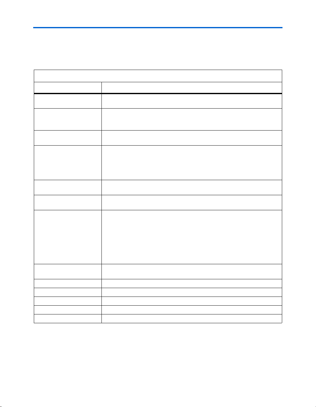
This document uses the typographic conventions shown in Table 1–2.
Conventions
Table 1–2. Typographic Conventions
Visual Cue Meaning
Bold Type with Initial
Capital Letters
bold type External timing parameters, directory names, project names, disk drive names,
Italic Type with Initial Capital
Letters
Italic type Internal timing parameters and variables are shown in italic type.
Initial Capital Letters Keyboard keys and menu names are shown with initial capital letters. Examples:
“Subheading Title” References to sections within a document and titles of on-line help topics are
Courier type Signal and port names are shown in lowercase Courier type. Examples: data1,
Command names, dialog box titles, checkbox options, and dialog box options are
shown in bold, initial capital letters. Example: Save As dialog box.
filenames, filename extensions, and software utility names are shown in bold
type. Examples: f
Document titles are shown in italic type with initial capital letters. Example: AN
75: High-Speed Board Design.
Examples: t
Variable names are enclosed in angle brackets (< >) and shown in italic type.
Example: <file name>, <project name>.pof file.
Delete key, the Options menu.
shown in quotation marks. Example: “Typographic Conventions.”
PIA
, \qdesigns directory, d: drive, chiptrip.gdf file.
MAX
, n + 1.
tdi, input. Active-low signals are denoted by suffix n, e.g., resetn.
Anything that must be typed exactly as it appears is shown in Courier type. For
example:
actual file, such as a Report File, references to parts of files (e.g., the AHDL
keyword
Courier.
1., 2., 3., and
a., b., c., etc.
● • Bullets are used in a list of items when the sequence of the items is not important.
■
v The checkmark indicates a procedure that consists of one step only.
1 The hand points to information that requires special attention.
r The angled arrow indicates you should press the Enter key.
f The feet direct you to more information on a particular topic.
viii Altera Corporation
Preliminary
Numbered steps are used in a list of items when the sequence of the items is
important, such as the steps listed in a procedure.
c:\qdesigns\tutorial\chiptrip.gdf. Also, sections of an
SUBDESIGN), as well as logic function names (e.g., TRI) are shown in
Page 9
Section I. Introduction
This section provides information about the High-Speed Development
Kit, Stratix GX Edition contents.
This section includes the following chapter:
■ Chapter 1. About this Kit
Revision History
The table below shows the revision history for Chapter 1.
Chapter(s) Date / Version Changes Made
1 July 2003 First publication.
Altera Corporation Section I–i
Preliminary
Page 10

Introduction High-Speed Development Kit, Stratix GX Edition User Guide
Section I–ii Altera Corporation
Preliminary
Page 11

1. About this Kit
General Description
Figure 1–1. Stratix GX Development Board
The High-Speed Development Kit, Stratix GX Edition is designed for the
development and rapid prototyping of applications that incorporate
single-channel or multi-channel transceiver interfaces up to 3.125 gigabits
per second (Gbps) and/or source-synchronous interfaces with dynamic
phase alignment (DPA) up to 1 Gbps per channel. Figure 1–1 shows the
development board included in the kit.
Altera Corporation Quartus II Version 3.0 1–1
July 2003
Page 12

Features High-Speed Development Kit, Stratix GX Edition User Guide
The development kit includes the following items:
■ Stratix GX Development Board—The development board has a variety
of connectors from the Stratix GX device to external sources that you
can use for a wide array of applications, including Gigabit Ethernet,
10 Gigabit Ethernet, OC-12/STM-4 and OC-48/STM-16
SONET/SDH, Fibre Channel (1 and 2 Gbps), System Packet Interface
– Level 4 Phase 2 (SPI-4.2) (also known as POS-PHY Level 4), PCI
Express, 8-bit RapidIO, and 1x/4x Serial RapidIO. You can use a
®
embedded processor to control the application, or you can
Nios
access an external processor via the PCI mezzanine card (PMC)
interface.
■ Board Design Files—The kit includes a complete package of schematic
and layout design files along with a viewer tool, which you can use
as reference to accelerate PCB design using the Stratix GX device.
■ Design Examples—The kit includes design examples that illustrate the
use of Stratix GX transceivers. You can use these design examples as
a reference when implementing your proprietary backplane
interface, accelerating the design, verification, and prototyping cycle.
■ Demonstrations—The kit includes two device programming files that
demonstrate a 10 Gigabit Ethernet MAC with a 10 Gigabit
attachment unit interface (XAUI) and a SPI-4.2 interface connected to
a 10-port multi-physical layer (PHY) device.
■ Loopback Connectors—The kit includes 2 cards with reciprocal source-
synchronous connectors wired for external loopback mode and 1
card for XCVR loopback. Additionally, the kit includes 4 loopback
cards for the SFP connectors.
■ Cables—The kit includes 4 SMA cables that you can use to connect to
an external oscilloscope or use for loopback testing of quad-channel
transceiver interfaces such as XAUI.
Features
1–2 Quartus II Version 3.0 Altera Corporation
■ Supports a wide array of applications, including:
● Gigabit and 10 Gigabit Ethernet
● 1 and 2 Gbps Fibre Channel
● OC-12/STM-4 and OC-48/STM-16 SONET/SDH
● SPI-4.2
● SDI
● PCI Express
● 8-bit RapidIO and 1x/4x Serial RapidIO
● PCI
● Proprietary backplane
July 2003
Page 13

About this Kit Documentation
■ Includes a broad array of external connectors, including:
● HM-Zd interconnect for SPI-4.2/DPA, compatible with Intel’s
10-Channel Gigabit Ethernet media access controller (MAC)
Evaluation Board (#IXD1110)
● SMA interconnect on two LVDS/DPA channels
● SMA interconnect on four transceiver channels
● HM-Zd interconnect on four transceiver channels, compatible
with Tyco’s XAUI HM-Zd Evaluation Backplane (#B024519-013)
● XPAK connector on four transceiver channels (optical module
not included)
● Four small form factor pluggable (SFP) optical connectors
(optics not included)
● Four high speed serial data connectors (HSSDC2)
● High-speed logic analyzer access, compatible with Agilent and
Tektronix connectorless probes
● 10/100 Ethernet MAC/PHY for remote device access
Documentation
The High-Speed Development Kit, Stratix GX Edition contains the
following documentation:
■ Stratix GX Development Board Data Sheet—Describes the
specifications for the board and explains how to use it. This
document is printed.
■ High-Speed Development Kit, Stratix GX Edition User Guide (this
document)—Describes how to use the kit, including setting up the
board, running the diagnostic tests, and describing the example
designs. This document is printed.
■ Stratix GX Board Design Guidelines—This document provides design
guidelines for the board. This document is printed.
■ Stratix GX Device Family Data Sheet—Provides the technical
specifications for Stratix GX devices.
■ AN 249: Implementing 10 Gigabit Ethernet XAUI in Stratix GX
Devices—Describes the fundamentals of 10 Gigabit Ethernet and
XAUI electrical specifications, and illustrates how to implement a
XAUI interface in a Stratix GX device.
■ POS-PHY Level 4 MegaCore Function User Guide—Provides the
specifications for the Altera POS-PHY Level 4 MegaCore
®
function
and explains how to use it.
■ 10 Gigabit Ethernet MAC Product Brief—Describes the features of the
10 Gigabit Ethernet MAC megafunction from AMPP
SM
partner
MorethanIP.
■ SONET/SDH Compiler User Guide—Provides the specifications of the
Altera SONET/SDH Framer and Overhead Processor MegaCore
function and explains how to use it.
Altera Corporation Quartus II Version 3.0 1–3
July 2003
Page 14

Documentation High-Speed Development Kit, Stratix GX Edition User Guide
■ PCI Compiler User Guide—Provides the specifications of the Altera
PCI MegaCore functions and explains how to use them.
■ DDR SDRAM Controller User Guide—Provides the specifications of
the Altera DDR SDRAM Controller MegaCore function and explains
how to use it.
1–4 Quartus II Version 3.0 Altera Corporation
July 2003
Page 15

Section II. Getting Started
This section describes how to get started with the board, including
describing the board components, explaining how to set up the board,
and describing how to perform the preloaded diagnostic tests.
This section includes the following chapters:
■ Chapter 2. Before You Begin
■ Chapter 3. Board Setup
■ Chapter 4. Run the Preloaded Diagnostic Tests
Revision History
The table below shows the revision history for these chapters.
Chapter(s) Date / Version Changes Made
2 - 4 July 2003 First publication.
Altera Corporation Quartus II Version 3.0 Section II–i
Preliminary
Page 16

Getting Started High-Speed Development Kit, Stratix GX Edition User Guide
Section II–ii Quartus II Version 3.0 Altera Corporation
Preliminary
Page 17

2. Before You Begin
Before using the kit or installing the software, be sure to check the
contents of the kit and inspect the board to verify that you received all of
the items. If any of these items are missing, contact Altera before you
proceed. You should also verify that your PC meets the software and
system requirements of the kit.
Development Kit Contents
The High-Speed Development Kit, Stratix GX Edition contains the
following items:
■ Stratix GX development board
■ ByteBlaster™ II cable
■ ATX power su p ply
■ 4 SMA cables
■ RS-232 cable
■ 3 mini-cards with reciprocal HM-Zd connectors wired for loopback
■ 4 mini-cards to loop back the SFP connectors
■ Stratix GX Reference Designs & Software CD-ROM
■ Quartus II Development Software CD-ROM (version 3.0)
■ High-Speed Development Kit, Stratix GX Edition User Guide (this
document)
■ Stratix GX Development Board Data Sheet
■ Stratix GX Board Design Guidelines
■ Introductory letter
The Stratix GX Reference Designs & Software CD-ROM contains all of the
supporting files and documentation, including:
■ Stratix GX development board schematic
■ Stratix GX development board layout file (Allegro format)
■ Stratix GX development board layout guidelines
■ Stratix GX development board test designs
■ Stratix GX development board example designs and demonstrations
■ 60-day evaluation versions of Altera MegaCore functions
■ Related documentation in Adobe PDF
Altera Corporation Quartus II Version 3.0 2–1
Page 18

Inspect the Board High-Speed Development Kit, Stratix GX Edition User Guide
Inspect the Board
f Refer to the Stratix GX Development Board Data Sheet for information on
Software Requirements
f Refer to “Set Up Licensing” for information on obtaining licenses for the
Place the board on an anti-static surface and inspect it to ensure that it has
not been damaged during shipment. Verify that all components are on
the board and appear intact.
1 The board can be damaged without proper anti-static handling.
Therefore, you should take anti-static precautions before
handling the board.
the board components and their locations.
You should install the following software before you begin using the kit.
■ Quartus
■ The software on the High-Speed Development Kit, Stratix GX Edition
CD-ROM.
software.
Figure 2–1 shows the development kit directory structure on the
Stratix GX Reference Designs & Software CD-ROM.
®
II software version 3.0 or higher.
2–2 Quartus II Version 3.0 Altera Corporation
Page 19

Before You Begin Software Requirements
g
Figure 2–1. Stratix GX Reference Designs & Software Directory Structure
<
path
>\Stratix_GX_kit
Demonstrations
Contains the files for the demonstrations provided with the kit.
SPI4
Contains a device programming file that demonstrates Stratix GX SPI-4.2 interoperability with
the Intel IXF1110 and PMC-Sierra S/UNI-10xGE 10-port Gigabit Ethernet MAC devices.
10GBEthernet
This demonstration application implements a 10-Gigabit Ethernet MAC connected to the
Stratix GX embedded SERDES device, providing an XAUI connection to an optional
Xenpak/XPAK optical transceiver module.
Supporting_docs
Contains the board schematics, layout files, layout guidelines, and documentation in Adobe PDF.
Test_designs
Contains the test designs described in the kit user guide.
Standard_test_designs
Contains the archived standard test designs.
Standard_sofs
Contains the SRAM Object Files (.sof) for the standard test designs.
Nios_tests_designs
Contains the archived Nios-based test designs.
Nios_sofs
Contains SOFs for the Nios test designs and run files.
Preloaded_test_files
Contains Pro
rammer Object Files (.pof) for the preloaded test designs.
Altera provides archived Quartus II projects for the designs included in
the kit. Before compiling an archived project, you must restore it. To
restore and compile, perform the following steps:
1. Choose Restore Archived Project (Project menu).
2. In the Archive name box, type the path and file name of the
Quartus II Archive File (.qar) you wish to restore, or select a QAR
File with Browse (...).
3. In the Destination folder box, type or select the path of the folder
into which you wish to restore the contents of the QAR File, or select
a folder with Browse (...).
4. Click Show log to view the Quartus II Archive Log File (.qarlog) for
the project you are restoring from the QAR File.
5. Click OK.
6. Compile the project.
Altera Corporation Quartus II Version 3.0 2–3
Page 20

Set Up Licensing High-Speed Development Kit, Stratix GX Edition User Guide
Set Up Licensing
You must have a valid license to use the Quartus II development software
and to compile and generate programming files for designs that include
Altera MegaCore functions. The kit includes a full, 1-year license for the
Quartus II development software and temporary 60-day evaluation
licenses for the Altera POS-PHY Level 4, SONET/SDH Framer and
Overhead Processor, PCI, and DDR SDRAM Controller MegaCore
functions. To purchase full licenses for the MegaCore functions, visit the
the Altera web site at www.altera.com or contact your local Altera sales
representative.
1 To design for Stratix GX devices using the Quartus II software,
you need a special FEATURE line. Therefore, you have to request
and install a license file before creating designs with the kit.
To obtain your Quartus II and temporary MegaCore licenses, perform the
following steps:
1. Point your web browser to the Altera web site at
www.altera.com/licensing.
2. Scroll to the Development Kit Licenses section of the Altera
Licensing Center page.
3. Click the High-Speed Development Kit, Stratix GX Edition link.
4. Follow the on-line instructions to request your license. A license file
is e-mailed to you.
5. To install your license, refer to “Specifying the License File” in the
Quartus II Installation & Licensing Manual for PCs, which is included
with the kit.
1 The 60-day period for MegaCore evaluation licenses starts from
the request date and cannot be renewed. After this period, you
will still be able to compile and simulate using these MegaCore
functions, but you will not be able to generate programming
files.
Next Steps
2–4 Quartus II Version 3.0 Altera Corporation
This user guide contains the following chapters to help you get started
working with the board:
■ “Board Setup” on page 3–1 explains how to setup and configure the
Stratix GX development board.
■ “Run the Preloaded Diagnostic Tests” on page 4–1 describes how to
set up and run each preloaded design and the required equipment.
■ “Perform the Production Diagnostic Tests” on page 5–1 explains
how to run the production tests.
Page 21

Before You Begin Next Steps
■ “Troubleshooting” on page 6–1 describes how to solve problems you
may encounter with the test designs or with setting up the board.
■ “Diagnostic Test Details” on page 7–1 explains each diagnostic test,
including board-level block diagrams, design-level block diagrams,
and simulations or screenshots of each test.
■ “Stratix GX SPI-4.2 Demonstration with 10-Port Gigabit Ethernet
MAC” on page 8–1 describes this provided demonstration.
■ “10-Gigabit Ethernet MAC Demonstration” on page 9–1 describes
this provided demonstration.
Altera Corporation Quartus II Version 3.0 2–5
Page 22

Next Steps High-Speed Development Kit, Stratix GX Edition User Guide
2–6 Quartus II Version 3.0 Altera Corporation
Page 23

The Stratix GX development board has a variety of interfaces and
features. See Figure 3–1 and Table 3–1.
Figure 3–1. Features of the Stratix GX Development Kit Board
3. Board Setup
Altera Corporation Quartus II Version 3.0 3–1
Page 24

High-Speed Development Kit, Stratix GX Edition User Guide
Table 3–1. Stratix GX Development Board Features
Feature Description
1 Power connector and circuitry
2 Configuration switches
3 Divide by 20 and divide by 2 clock circuitry
4 Stratix Mictor connector
5 Stratix 20-pin test header
6 10/100 Ethernet interface
7 Exansion prototype card (PROTO1) interface
8 On-board flash interface
9 RS-232 interface for Stratix and Stratix GX devices
10 General-purpose interface (user pushbutton switches, dipswitches, LEDs, and displays)
11 Configuration circuitry
12 Stratix device
13 Source synchronous HM-Zd SPI-4.2 interface
14 Clock source (crystal oscillators and clock input and output)
15 DPA SMA interface
16 Edge-launched XCVR SMA connectors
17 XPAK interface
18 Tektronix high-speed differential probe for Stratix GX/Stratix device bridge
19 MDIO interface for XPAK
20 Stratix GX 20-pin test header
21 Agilent high-speed differential probe for source synchronous (HM-Zd SPI-4.2) interface
22 SFP interface
23 Stratix GX device
24 Stratix GX Mictor connector
25 HSSDC2 interface
26 Vertical launched XCVR SMA connectors
27 DDR SDRAM interface
28 Recovered clock SMA connectors
29 XAUI HM-Zd interface
Not shown PMC interface (on the back of the board)
Compact flash interface (on the back of the board)
3–2 Quartus II Version 3.0 Altera Corporation
Page 25
Board Setup Required Hardware
Required Hardware
Table 3–2. Required Equipment
Hardware Manufacturer Part Number Quantity
Stratix GX Development Board Altera 1
ATX Power Supply Sparkle Power FSP250-60GTA 1
Programming Cable Altera ByteBlaster II 1
SMA DC Block (1) Any 2
SMA 20-dB 50-Ω Attenuator (1) Any 1
High-Speed Digital Sampling Oscillocope (1), (2) Tektronix CSA8000 1
3-Foot SMA Cable (1) Any 3
Note:
(1) This item is required to view the XCVR eye.
(2) You can also use other oscilloscopes.
Power Up the Board & View the XCVR Eye
To power up the Stratix GX development board, you need the hardware
listed in Table 3–2. See “Development Kit Contents” on page 2–1 for a list
of items provided in the kit.
Perform the following steps to power up the Stratix GX development
board. You will set switches on the board so that the Stratix GX device
displays the transceiver (XCVR) eye in an oscilloscope.
1 Before you attempt to power up the board, make sure that you
have the equipment listed in Table 3–2.
1. Set switch SW3 to off (middle position).
2. Connect one end of the ATX power supply to J31 and the other end
to a power outlet.
3. Set the Stratix GX device switches as shown in Table 3–3. These
settings display the XCVR eye.
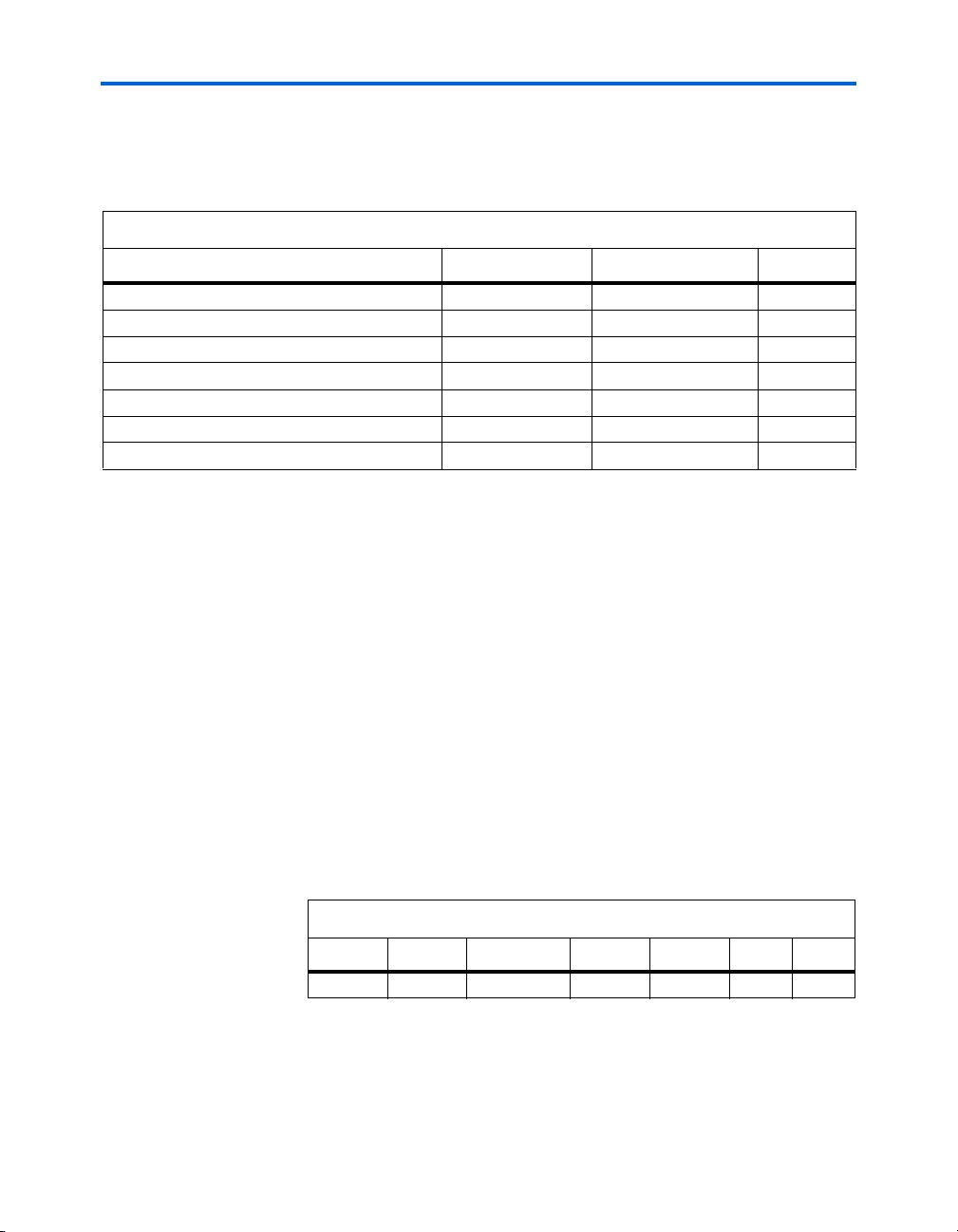
Table 3–3. Stratix GX XCVR Eye Switches Settings
SW1 SW2 SW4 SW5 SW8 J48 J90
YES NO EPC16 STD 000 X X
4. Set switch SW3 to the on position (all of the way up). All of the
board LEDs illuminate.
Altera Corporation Quartus II Version 3.0 3–3
Page 26

Power Up the Board & View the XCVR Eye High-Speed Development Kit, Stratix GX Edition User Guide
The Stratix GX development board is powered up. To view the Stratix GX
XCVR eye, perform the following steps:
1. Place a DC block on the signals TX_N3 (J25) and TX_P3 (J17).
2. Place the SMA attenuator on J97.
3. Connect one end of an SMA cable to the attenuator and connect the
other end to the trigger input of the oscilloscope.
4. Connect one end of an SMA cable to J25 and connect the other end
to an input channel of the oscilloscope.
5. Connect one end of an SMA cable to J17 and connect the other end
to an input channel of the oscilloscope.
6. Set the switch SW9 to select the crystal oscillator.
7. On the oscilloscope, set the vertical setting on each channel to
52 mV/div.
8. Set the oscilloscope’s horizontal setting to 100 ps/div.
9. On the oscilloscope’s trigger section, press the SET TO 50% button.
10. Turn on and set the math channel to C2-C1.
11. Turn off channels 1 and 2. The oscilloscope should capture an eye
pattern similar to the one shown in Figure 3–2.
3–4 Quartus II Version 3.0 Altera Corporation
Page 27

Board Setup Power Up the Board & View the XCVR Eye
Figure 3–2. Eye Pattern for CSA8000
12. Stratix GX devices can dynamically control the transceiver’s VOD
and pre-emphasis settings. To view this control, perform the
following steps.
a. Press the adjust pre-emphasis pushbutton (S4). You should see
the pre-emphasis change on the oscilloscope. There are 6 preemphasis settings: pressing S4 5 times in succession cycles
through the settings. Pressing S4 a sixth time sets the
transceiver back to the original setting. The value of the setting
is indicated by the left digit of the Stratix GX seven segment
display (D9).
b. Press the adjust VOD pushbutton (S5). You should see the VOD
change on the oscilloscope. There are 6 VOD settings: pressing
S5 5 times in succession cycles through the settings. Pressing S5
a sixth time sets the transceiver back to the original setting. The
value of the setting is indicated by the right digit of the Stratix
GX seven segment display (D9).
Altera Corporation Quartus II Version 3.0 3–5
Page 28

Power Up the Board & View the XCVR Eye High-Speed Development Kit, Stratix GX Edition User Guide
3–6 Quartus II Version 3.0 Altera Corporation
Page 29

4. Run the Preloaded Diagnostic Tests
Each interface on the Stratix GX development board has an associated
diagnostic test that exercises the interface at the supported I/O rates.
Although the tests are not exhaustive, they help you confirm that each
interface runs according to its intended design. A subset of the diagnostic
tests are loaded into the Stratix GX development board’s configuration
devices, making it easy for you to run any of the tests when you power
up the board. This chapter describes how to set up and perform these
preloaded diagnostic tests, including:
■ User I/O
■ Stratix GX Double Data Rate (DDR) SDRAM Interface
■ Stratix GX HM-Zd SPI-4.2 Loopback
■ Stratix GX HM-Zd XCVR Loopback
■ Stratix GX SFP XCVR Loopback
■ Stratix GX XCVR Eye Diagram
The following sections describe how to perfom each test, including the
equipment you need to perform each test, how to set up the board, and
the test procedure. Table 4–1 shows the switch settings you must make to
load the designs on power up. For more details on these designs, refer to
Chapter 7, Diagnostic Test Details.
Table 4–1. Factory-Default Switch Settings
Diagnostic Test SW1 SW2 SW4 SW5 SW7 SW8 (1) J48 J90
XCVR Eye Diagram YES NO EPC16 STD --- 000 X X
DDR YES NO EPC16 STD --- 011 X X
HM-Zd SPI-4.2 YES NO EPC16 STD --- 001 X X
HM-Zd XCVR Loopback YES NO EPC16 STD --- 001 X X
SFP XCVR Loopback YES NO EPC16 STD --- 001 X X
User I/O NO NO EPC16 STD 111 111 X X
Note:
(1) Slider 3 is the MSB and slider 1 is the LSB. A slider in the up position is 0 and a slider in the down position is 1.
User I/O
Altera Corporation Quartus II Version 3.0 4–1
The user I/O design tests all of the user LEDs, dipswitches, pushbuttons,
and 7-segment displays on the board (the Stratix and Stratix GX devices
each have a set). One pair of pushbuttons controls each device’s user
Page 30

User I/O High-Speed Development Kit, Stratix GX Edition User Guide
LEDs, while the other pair increments or decrements the counter shown
on the 7-segment display. The dipswitches enter numbers on each
device’s 7-segment display.
Required Hardware
In addition to the board, you need the Altera-provided ATX power
supply.
Test Se t up
Perform the following steps to set up the user I/O test.
1. Set the switches as shown in Table 4–1 for the user I/O test.
2. Connect the power supply to the board.
3. Confirm that the Stratix and Stratix GX devices have finished
configuration (the GX_CONF_DONE (D7) and S_CONF_DONE
(D6) LEDs illuminate as shown in Figure 4–1).
Figure 4–1. GX_CONF_DONE, S_CONF_DONE & User I/O LEDs
PB0
4–2 Quartus II Version 3.0 Altera Corporation
PB1
PB2
PB3
S_CONF_DONE
GX_CONF_DONE
Page 31

Run the Preloaded Diagnostic Tests User I/O
Run the User I/O Test
Perform the following steps to execute the test for the Stratix GX device
user I/O.
1. Set all of the Stratix GX user dipswitches (S11) to 0.
2. Press GX_CLR (S14) to reset the design. When the pushbutton is
pressed, the GX_CLR LED (D16) illuminates. When you release the
pushbutton, the 7-segment display (D9) shows 00.
3. Press the Stratix GX channel pushbutton switches, Stratix_GX_PB_0
(S2) for up and Stratix_GX_PB_1 (S3) for down. The channel
numbers on the Stratix GX 7-segment display (D9) increment and
decrement as you press S2 and S3, respectively.
4. Press S14 once.
5. Press S2 three times. D9 displays 03.
6. Press S3 four times. D9 displays 99.
7. Press the Stratix GX volume pushbutton switches, Stratix_GX_PB_2
(S4) for up and Stratix_GX _PB_3 (S5) for down. As you press S4
and S5, the number of Stratix_GX LEDs (D10-15) that are
illuminated should increment and decrement, respectively.
8. Press S14 once.
9. Press S4 six times. All of the Stratix_GX LEDs illuminate.
10. Press S5 six times. All of the Stratix_GX LEDs turn off.
11. Using the Stratix GX user dipswitches (S11), enter the binary
number 15.
a. Set dipswitches 4-1 to 1.
b. Set dipswitch 7 to the up position and then to the down
position to enter the value. D9 displays the number 15.
12. Enter the binary number 127.
a. Set dipswitches 7-1 to 1.
b. Set dipswitch 8 to the up position and then to the down
position to enter the value. D9 displays the number 99.
Altera Corporation Quartus II Version 3.0 4–3
Page 32

User I/O High-Speed Development Kit, Stratix GX Edition User Guide
You are finished testing the Stratix GX device user I/O. Perform the
following steps to execute the test for the Stratix device user I/O.
13. Set all of the Stratix user dipswitches (D6) to 0.
14. Press S_CLR (S12) to reset the design. The S_CLR LED (D24)
illuminates and the 7-segment display (D8) shows 00.
15. Press the Stratix channel pushbutton switches, Stratix_PB_0 (S8) for
up and Stratix_PB_1 (S9) for down. The channel numbers on the 7segment display (D8) increment and decrement.
16. Press S12 once.
17. Press S8 three times. D8 displays 03.
18. Press S9 four times. D8 displays 99.
19. Press the Stratix volume pushbutton switches, Stratix_PB_2 (S10) for
up and Stratix_PB_3 (S7) for down. The number of illuminated
Stratix LEDs increment and decrement.
20. Press S12 once.
21. Press S10 six times. All of the LEDs illuminate.
22. Press S7 six times. All of the LEDs turn off.
23. Enter the binary number 15.
a. Set dipswitches 4-1 to 1.
b. Set dipswitch 8 to the up position and then to the down
position to enter the value. D8 displays the number 15.
24. Enter the binary number 127.
a. Set dipswitches 7-1 to 1.
b. Set dipswitch 8 to the up position and then to the down
position to enter the value. D8 displays the number 99.
You have finished the user I/O test.
4–4 Quartus II Version 3.0 Altera Corporation
Page 33

Run the Preloaded Diagnostic Tests Stratix GX DDR SDRAM Interface
Stratix GX DDR SDRAM Interface
Figure 4–2. RS-232 Connector
Serial Port for
Stratix Device
Serial Port for
Stratix GX Device
The Stratix GX DDR SDRAM interface connects to a 184-pin, 200-MHz
Micron DDR DIMM module. To test this interface, you use a Nios
embedded processor-based test that you run from the SOPC Builder SDK
Shell. You observe the test output in the shell. An RS-232 cable connected
to your PC’s COM 1 port allows communication between the board and
the software running on the PC. The RS-232 connector serves the Stratix
GX device when the serial cable is attached to the bottom connector and
the Stratix device when the serial cable is attached to the top connector as
shown in Figure 4–2.
Required Hardware & Software
The Stratix GX DDR SDRAM test design uses the following equipment
and software:
■ DDR DIMM module
■ RS-232 cable
■ ATX power su p ply
■ Nios embedded processor version 2.0 or higher
Altera Corporation Quartus II Version 3.0 4–5
Page 34

Stratix GX DDR SDRAM Interface High-Speed Development Kit, Stratix GX Edition User Guide
Test Se t up
Perform the following steps to set up the test.
1. Remove power from the board.
2. Insert the DDR DIMM module in the location defined in Figure 4–3.
Figure 4–3. Inserting DDR DIMM
3. Attach one end of the RS-232 cable to your PC’s COM 1 port and the
other end to the bottom connector of the RS-232 serial port on the
board.
4. Set the board’s switches as shown in Table 4–1 for this test.
5. Supply power to the board.
6. Confirm that the Stratix GX device has finished configuration (the
GX_CONF_DONE (D7) LED illuminates).
Run the Stratix GX DDR SDRAM Interface Test
Perform the following steps to run the test.
1. Choose Programs > Altera > SOPC Builder <version> > SOPC
Builder SDK Shell (Windows Start menu).
1 This shell may be named Nios SDK Shell in older versions
of the Nios embedded processor.
2. Change to the Nios SOFs directory by typing the following
command:
cd /Stratix_GX_kit/Test_designs/Nios_test_designs/
Nios_sofs r
3. Type nr -t r to open a terminal window that connects to COM 1.
4–6 Quartus II Version 3.0 Altera Corporation
Page 35

Run the Preloaded Diagnostic Tests Stratix GX DDR SDRAM Interface
4. Press the Enter key twice in the terminal window. You should be at
a Nios prompt.
5. Confirm that you are connected to the Nios processor running on
the board by pressing the Enter key a few times in the terminal
window to display the processor’s memory contents.
6. Exit the terminal window by pressing the Ctrl + C keys.
7. Type nr DDR.srec r to start the DDR test. Observe the results to
see if any errors are reported. Figure 4–4 shows the text that should
display in the shell.
Figure 4–4. DDR Test Display in SOPC Builder SDK Shell
======================================================
= Altera GX Development Board DDR SDRAM Demonstration =
= - Nios v2.2 (66MHz) =
= - Altera DDR SDRAM Controller v1.1.0 (200MHz) =
= - Avalon test interface to DDR SDRAM Controller =
======================================================
Doing a sequence of 100 back-to-back writes (of 8) followed by 100 back-to-back
reads (of 8)
Repeating this test 20000 times
Testing... [####################]
Walking ones on the addresses test
Repeating this test 20000 times
Testing... [####################]
Burst length test (burst reads and writes of 2,4 and 8)
5 sequences of 4 write & read bursts
Repeating this test 20000 times
Testing... [####################]
Entire DIMM write and read test
Write the entire DIMM with the address of each location,
Then read each location to check that the address and data are the same.
Writing... [####################]
Finished writing.
Reading... [####################]
Read and checked 8388608 locations (128 Mb).
======================================================
= END OF TEST =
= Type "g0" and press Enter to restart the test =
Altera Corporation Quartus II Version 3.0 4–7
Page 36

Stratix GX HM-Zd SPI-4.2 Loopback High-Speed Development Kit, Stratix GX Edition User Guide
8. The test continues until you press the Ctrl + C keys. Press these keys
to stop the status display in the SOPC Builder SDK Shell.
9. Press S2 to stop the test.
Stratix GX HMZd SPI-4.2
Loopback
The Stratix GX HM-Zd SPI-4.2 loopback test design tests the SPI-4.2
source synchronous signals at up to 1 Gbps using the provided HM-ZD
SPI-4.2 loopback cards.
Required Hardware
This test requires the following hardware:
■ HM-Zd SPI-4.2 loopback cards (labeled J108 and J109)
■ ATX power su p ply
Test Se t up
Perform the following steps to set up the test.
1. Remove power from the board.
2. Install the HM-Zd SPI-4.2 loopback cards as shown in Figure 4–5.
3. Set the board’s switches as shown in Table 4–1 for this test.
4–8 Quartus II Version 3.0 Altera Corporation
Page 37

Run the Preloaded Diagnostic Tests Stratix GX HM-Zd SPI-4.2 Loopback
Figure 4–5. Install the HM-Zd SPI-4.2 Loopback Cards
4. Supply power to the board.
5. Confirm that the Stratix GX device has finished configuration (the
GX_CONF_DONE (D7) LED illuminates).
Run the Stratix GX HM-Zd SPI-4.2 Loopback Test
Perform the following steps to run the test.
1. Setthe Stratix GX dipswitch 5 to 1 (up position).
2. Press the reset pushbutton switch (GX_CLR).
3. Press the start pushbutton switch (Stratix_GX_PB_0). Several LEDs
illuminate.
● LED0 is the high-speed data match LED. If it illuminates, the test
is successful.
● LED1 indicates that the GX device has received the data.
Altera Corporation Quartus II Version 3.0 4–9
Page 38

Stratix GX HM-Zd XCVR Loopback High-Speed Development Kit, Stratix GX Edition User Guide
● LED2 indicates a per channel match. This LED is used for the per
channel feature.
● LED3 indicates that the test has started.
● LED4 is the match LED for the low-speed control signals.
● LED5 is the error indicator.
4. Press the stop pushbutton switch (GX PB1) to stop the device from
transmitting data.
5. Press the reset pushbutton switch (GX_CLR).
6. Press the Stratix_GX_PB_0.
7. Inject an error by pressing Stratix_GX_PB_2 (S4) once. The
Stratix GX 7-segment display (D9) shows 01 and LED5 illuminates.
8. Inject two more errors by pressing S4 twice. D9 displays 03.
Stratix GX HMZd XCVR
Loopback
The Stratix GX HM-Zd XCVR loopback test design tests the HM-Zd
XCVR signals at up to 3.125 Gbps using the provided HM-Zd XCVR
loopback card.
Required Hardware
This test requires the following hardware:
■ HM-Zd XCVR loopback card (labeled J1)
■ ATX power su p ply
Test Se t up
Perform the following steps to set up the test.
1. Remove power from the board.
2. Install the HM-Zd XCVR loopback card as shown in Figure 4–6.
4–10 Quartus II Version 3.0 Altera Corporation
Page 39

Run the Preloaded Diagnostic Tests Stratix GX HM-Zd XCVR Loopback
Figure 4–6. Install the HM-Zd XCVR Loopback Card
3. Set the board’s switches as shown in Table 4–1 for this test.
4. Supply power to the board.
5. Confirm that the Stratix GX device has finished configuration (the
GX_CONF_DONE (D7) LED illuminates).
Run the Stratix GX HM-Zd XCVR Loopback Test
Perform the following steps to run the test.
1. Set Stratix GX user dipswitches 5 and 6 to the up position to set the
XCVR setting to HM-Zd.
2. Press the reset pushbutton switch (GX_DEV CLR) to initialize the
design. The GX_DEV_CLR LED illuminates.
3. Press the start pushbutton switch (GX PB0). Several LEDs
illuminate.
● LED0, LED1, LED2, and LED3 are the match lights on a per
channel basis. They illuminate if the test is successful.
● LED4 indicates that the test is running.
● LED5 is the error signal.
4. Press the stop pushbutton switch (GX PB1) to stop the device from
transmitting.
5. Press the reset pushbutton switch (GX_DEVCLR).
Altera Corporation Quartus II Version 3.0 4–11
Page 40

Stratix GX SFP XCVR Loopback High-Speed Development Kit, Stratix GX Edition User Guide
6. Press the start pushbutton switch (Stratix_GX_PB_0).
7. Inject an error by pressing Stratix_GX_PB_2 (S4) once. The
Stratix GX 7-segment display (D9) shows 01 and Stratix GX LED5
illuminates.
8. Inject two more errors by pressing S4 twice. D9 displays 03.
Stratix GX SFP XCVR Loopback
The Stratix GX SFP XCVR loopback test design tests the SFP XCVR
signals at up to 2.488 Gbps using the provided SFP XCVR loopback cards.
Required Hardware & Software
This test requires the following hardware and software:
■ SFP XCVR loopback cards
■ ATX power su p ply
Test Se t up
To set up the test, perform the following steps.
1. Remove power from the board.
2. Insert the SFP loopback cards on the board as shown in Figure 4–6.
3. Attach the SFP loopback card (labeled J3 on the card) to the SFP
transceiver connectors at J54, J64, J45, and J38 as shown in
Figure 4–7.
4–12 Quartus II Version 3.0 Altera Corporation
Page 41

Run the Preloaded Diagnostic Tests Stratix GX SFP XCVR Loopback
Figure 4–7. Attach the XCVR SFP Loopback Cards
4. Set the board’s switches as shown in Table 4–1 for this test.
5. Supply power to the board.
6. Confirm that the Stratix GX device has finished configuration (the
GX_CONF_DONE (D7) LED illuminates).
Run the Stratix GX SFP XCVR Loopback Test
Perform the following steps to run the test.
1. Set Stratix GX user dipswitches 5 and 6 to the down position to set
the XCVR setting to SFP.
2. Press the reset pushbutton switch (GX_DEV CLR) to initialize the
design. The GX_DEV_CLR LED illuminates.
3. Press the start pushbutton switch (GX PB0). Several LEDs
illuminate.
● LED0, LED1, LED2, and LED3 are the match lights on a per
channel basis. They illuminate if the test is successful.
● LED4 indicates that the test is running.
● LED5 is the error signal.
4. Press the stop pushbutton switch (GX PB1) to stop the device from
transmitting.
Altera Corporation Quartus II Version 3.0 4–13
Page 42

Stratix GX XCVR Eye Diagram High-Speed Development Kit, Stratix GX Edition User Guide
5. Press the reset pushbutton switch (GX_DEVCLR).
6. Press the start pushbutton switch (Stratix_GX_PB_0).
7. Inject errors by pressing Stratix_GX_PB_2 (S4) once. The Stratix GX
7-segment display (D9) shows 01 or more and Stratix GX LED5
illuminates. Because this test runs all channels at once, the Stratix
GX 7-segment display (D9) may show more than one error when
you press Stratix_GX_PB_2 (S4).
8. Inject two more errors by pressing S4 twice. D9 displays 03 or more.
Stratix GX XCVR Eye Diagram
f To perform this test, refer to “Power Up the Board & View the XCVR
The Stratix GX XCVR eye test design produces an eye on an oscilloscope
at 3.125 Gbps using the on-board crystal oscillator and SMA cables. This
design also shows the dynamic control of the Stratix GX device for both
the pre-emphasis and VOD settings using the pushbutton switches S4
and S5. For this design, the Stratix GX transceiver block has the parameter
settings shown in Table 4–2.
Table 4–2. Transceiver Block Parameter Settings
Parameter Setting
Data Rate 3.125 GHz
Clock In 156.25 MHz
PLL Clock 156.25 MHz
PLL DC Coupling Disabled
PLL Bandwidth High
PPM Threshold 1000
8b/10b Encoder/Decoder Bypassed
Run Length Violation Bypassed
Rx Bandwidth Disabled
Word Alignment Mode Manual
Alignment Pattern 0101111100
Eye” on page 3–3.
4–14 Quartus II Version 3.0 Altera Corporation
Page 43

Section III. Diagnostic
Tests
Each interface on the Stratix GX development board has an associated
diagnostic test that exercises the interface at the supported I/O rates.
Although the tests are not exhaustive, they help you confirm that each
interface runs according to its intended design. The production tests
execute each diagnostic test. Altera executes the production tests on every
Stratix GX development board to confirm that all of the interfaces pass.
This section includes the following chapters:
■ Chapter 5. Perform the Production Diagnostic Tests
■ Chapter 6. Troubleshooting
■ Chapter 7. Diagnostic Test Details
Revision History
The table below shows the revision history for these chapters.
Chapter(s) Date / Version Changes Made
5 - 7 July 2003 First publication.
Altera Corporation Quartus II Version 3.0 Section III–i
Preliminary
Page 44

Diagnostic Tests High-Speed Development Kit, Stratix GX Edition User Guide
Section III–ii Quartus II Version 3.0 Altera Corporation
Preliminary
Page 45

5. Perform the Production Diagnostic Tests
Required Hardware & Software
Set Up the Board
The following list describes the hardware and software you need to run
the production diagnostic tests.
■ Windows-based PC
■ Quartus II software
■ Parallel port cable
■ Serial port cable
■ PMC card (part number 853-10010 PMC100TX)
■ 10/100-Mbit Ethernet network-interface daughter board (part
number NIOS-EDKX)
■ Six to ten short (1-foot) SMA cables
■ High-Speed Development Kit, Stratix GX Edition
● Stratix GX development board revision C
● ATX power su p ply
● ByteBlaster II cable
● Programming files
● Four long (3-foot) SMA cables
● HM-Zd loopback cards
● SFP loopback card
● Micron DDR DIMM
● Compact flash card
The following procedure describes how to set up the board, including
attaching the daughter cards and cables.
1. Install the PMC card on the back side of the board as shown in
Figure 5–1.
Altera Corporation Quartus II Version 3.0 5–1
Page 46

Set Up the Board High-Speed Development Kit, Stratix GX Edition User Guide
Figure 5–1. Attach the PMC Card
2. Attach the HM-Zd SPI-4.2 loopback card (labeled J108 on the card)
to the connector at J108, which is located on the bottom edge of the
board as shown in Figure 5–2.
3. If your version of the Stratix GX development board has an
EP1SGX40GF1020C5 device, you may also need to attach a second
HM-Zd loopback card (labeled J109 on the card) to the connector at
J109 for the optional differential status signals.
Figure 5–2. Attach the HM-Zd Loopback Card
5–2 Quartus II Version 3.0 Altera Corporation
Page 47

Perform the Production Diagnostic Tests Set Up the Board
4. Install six short SMA cables to the DPA SMA connectors:
● Connect DPA_CLKOUT (P & N) to DPA_CLKIN
● Connect DPA_TX0 (P & N) to DPA_RX0
● Connect DPA_TX1 (P & N) to DPA_RX1
See Figure 5–3.
1 Take care to connect the cables to the proper connectors and
ensure that the cables are completely seated.
Figure 5–3. Connect the Short SMA Cables for the SS DPA test
5. Install eight SMA cables to the transceiver SMA connectors as
shown in Figures 5–4 and 5–5. Do not overtighten the connectors
(using your fingers is good enough). Connect TX_P[3:0] to
RX_P[3:0] and TX_N[3:0] to RX_N[3:0].
1 Take care to connect the cables to the proper connectors
(there are 2 sets of connectors, 8 vertical launch and 8 edge
launch). Channels 0 and 1 are the edge launch and Channels
2 and 3 are the vertical launch connectors.
Altera Corporation Quartus II Version 3.0 5–3
Page 48

Set Up the Board High-Speed Development Kit, Stratix GX Edition User Guide
Figure 5–4. Connnect the Long SMA Cables to the Edge Launch Connectors
Figure 5–5. Attach Short SMA Cables to the Vertical Launch Connectors
6. Attach the HM-Zd XCVR loopback card (labeled J1 on the card) to
the HM-Zd transceiver connector as shown in Figure 5–6.
5–4 Quartus II Version 3.0 Altera Corporation
Page 49

Perform the Production Diagnostic Tests Set Up the Board
Figure 5–6. Attach the XCVR HM-Zd Loopback Card
7. Attach the SFP loopback card (labeled J3 on the card) to the SFP
transceiver connector at J54 as shown in Figure 5–7.
Figure 5–7. Attach the XCVR SFP Module
8. Attach the XPAK module to the XPAK transceiver connector at U27
as shown in Figure 5–8.
Altera Corporation Quartus II Version 3.0 5–5
Page 50

Set Up the Board High-Speed Development Kit, Stratix GX Edition User Guide
Figure 5–8. Attach the XCVR XPAK Module
9. Attach the HSSDC2 loopback cables to the HSSDC2 transceiver
connectors at J23 through J32 and J15 through J11 as shown in
Figure 5–9.
5–6 Quartus II Version 3.0 Altera Corporation
Page 51

Perform the Production Diagnostic Tests Set Up the Board
Figure 5–9. Attach the XCVR HSSDC2 Loopback Cables
10. Attach the DDR DIMM module to the DDR connector shown in
Figure 5–10.
Figure 5–10. Attach the DDR DIMM
11. Attach the 10/100-Mbit Ethernet network-interface daughter card to
the board as shown in Figure 5–11.
Figure 5–11. Attach the 10/100 Ethernet Network-Interface Card
Expansion Prototype
Card (PROTO1)
Connector
Altera Corporation Quartus II Version 3.0 5–7
Page 52

Set Up the Board High-Speed Development Kit, Stratix GX Edition User Guide
12. Attach the one end of the parallel cable to the PC’s parallel port if it
is not already attached.
13. Connect one end of the ByteBlaster II cable to the parallel cable.
14. Connect the other end of the ByteBlaster II cable to the JTAG header
(J87) on the Stratix GX development board, as shown in Figure 5–12.
Align the red edge of the cable with pin 1.
Figure 5–12. Attach the ByteBlaster II Cable
15. Move the power selection switch (SW3) to the middle position (off).
16. Attach the main power cable from the ATX supply to the power
connector (J31) on the board.
17. Set the Stratix bypass (SW1) and Stratix GX bypass (SW2) switches
to NO.
18. Set the configuration switch (SW4) to PS_HDR as shown in
Figure 5–13.
5–8 Quartus II Version 3.0 Altera Corporation
Page 53

Perform the Production Diagnostic Tests Set Up the Board
Figure 5–13. Power, Bypass & Configuration Switches
Power
Switch SW3
Configuration
Switch SW4
Stratix GX Device
Bypass Switch SW2
Stratix Device
Bypass Switch SW1
19. Set switches SW6 and SW9 to OSC, which is the up position.
20. Set the user dipswitches, S6 and S11, to zero, which is the down
position.
Figure 5–14 shows the board after you have attached all of the
daughter cards and cables, and set all of the switches.
Altera Corporation Quartus II Version 3.0 5–9
Page 54

Perform the Standard Tests High-Speed Development Kit, Stratix GX Edition User Guide
Figure 5–14. Board Completely Set Up
21. Power up the board by moving switch SW3 to the on position. The
board power ups with all of the user LEDs illuminated and the
7-segment displays turned on.
The board is now set up and you are ready to perform the tests.
Perform the Standard Tests
In this section you will perform all of the standard tests. For each test, you
will load a SOF onto the board. These SOFs are located in the
Stratix_GX_kit\test_designs\standard_test_designs\standard_sofs
directory.
1 Table 5–1 on page 5–36 is a worksheet for the tests. You should
have a printed copy of this worksheet when you perform the
tests so that you can note the test results in the appropriate
row/column in the worksheet.
User I/O
For this test, perform the following steps.
1. Run the Quartus II software. Keep the software open until you
finish all of the tests.
2. Choose Programmer (Tools menu). Leave the Programmer open
until you finish all of the tests.
5–10 Quartus II Version 3.0 Altera Corporation
Page 55

Perform the Production Diagnostic Tests Perform the Standard Tests
3. Click Auto-Detect. The Stratix, Stratix GX, and 2 EPC16 devices
display in the JTAG chain.
4. Change the programming file for the Stratix GX device:
a. Right-click the filename next to the Stratix GX device.
b. Browse to the standard SOFs directory.
c. Select the file GX40_User_IO.sof.
d. Click Open. Wait until the checksum field is updated.
5. Change the programming file for the Stratix device to
STX40_User_IO.sof using the steps described above. Wait until the
checksum field is updated.
6. Turn on the Program/Configure option for the Stratix and
Stratix GX devices. See Figure 5–15.
Figure 5–15. Quartus II Programmer for the User I/O Test
7. Click Start to configure both devices. When configuration is
complete for both devices, the GX_CONF_DONE (D7) and
S_CONF_DONE (D6) LEDs illuminate as shown in Figure 4–1 on
page 4–2.
8. Test the user I/O for the Stratix GX device by performing steps 1
through 12 in “Run the User I/O Test” on page 4–3.
Altera Corporation Quartus II Version 3.0 5–11
Page 56

Perform the Standard Tests High-Speed Development Kit, Stratix GX Edition User Guide
9. If all of the tests pass, write “PASS” in the column under Stratix GX
in the User I/O row in Table 5–1 on page 5–36.
10. Test the user I/O for the Stratix device by performing steps 13
through 24 in “Run the User I/O Test” on page 4–3.
11. If all of the tests pass, write “PASS” in the column under Stratix in
the User I/O row in the worksheet (Table 5–1 on page 5–36).
Stratix GX-to-Stratix Bridge
For this test, perform the following steps in the Programmer.
1. Change the programming file for the Stratix GX device to
GX40_Bridge.sof.
2. Change the programming file for the Stratix device to
STX40_Bridge.sof. Wait until the checksum field is updated.
3. Turn on the Program/Configure option for the Stratix and
Stratix GX devices.
Figure 5–16 shows the Programmer after you have done these steps.
Figure 5–16. Quartus II Programmer for the Stratix GX-to-Stratix Bridge Test
4. Click Start to configure both devices. When configuration is
complete for both devices, the GX_CONF_DONE (D7) and
S_CONF_DONE (D6) LEDs illuminate.
5–12 Quartus II Version 3.0 Altera Corporation
Page 57

Perform the Production Diagnostic Tests Perform the Standard Tests
5. Although this design uses both the Stratix and Stratix GX devices,
the Stratix GX device controls it. Set all of the Stratix GX user
dipswitches to 0.
6. Press GX_CLR (S14) to reset the design. The GX_CLR (D16) LED
illuminates and the Stratix GX LEDs 0 through 4 (D10, D11, D12,
D13, and D14) should be off. Additionally, the Stratix LEDs 0 and 1
(D18 and D19) illuminate while the rest are off.
7. Press the start pushbutton switch (Stratix_GX_PB_0). Several LEDs
illuminate.
● Stratix GX LED0 is the match LED. If it illuminates, the test is
successful.
● Stratix GX LED1 indicates the test has started.
● Stratix GX LED2 indicates that the GX device is transmitting to
the Stratix device.
● Stratix GX LED3 indicates that the GX device has received the
data from the Stratix device.
● Stratix GX LED5 illuminates if there is an error.
8. Press the stop pushbutton switch (Stratix_GX_PB_1) to stop the
device from transmitting.
9. Press the reset pushbutton switch (GX_CLR).
10. Press the start pushbutton switch (Stratix_GX_PB_0).
11. Inject an error by pressing Stratix_GX_PB_2 (S4) once. The number
01 displays on the Stratix GX 7-segment display (D9) and Stratix GX
LED5 illuminates.
12. Inject two more errors by pressing S4 twice. 03 displays on the
Stratix GX 7-segment display (D9).
13. Press start and then reset three times to insure that the test is
working.
14. If all of these tests pass, write the word “PASS” in the column under
Stratix and Stratix GX in the row Stratix GX-to-Stratix Bridge in the
worksheet.
Altera Corporation Quartus II Version 3.0 5–13
Page 58

Perform the Standard Tests High-Speed Development Kit, Stratix GX Edition User Guide
Source Synchronous HM-Zd Interface (Stratix GX HM-Zd SPI 4.2)
For this test, perform the following steps in the Programmer.
1. Change the programming file for the Stratix GX device to
GX40_SS_HMZd.sof. Wait until the checksum field is updated.
2. Turn on the Program/Configure option for the Stratix GX device.
Figure 5–17 shows the Programmer after you have done these steps.
Figure 5–17. Quartus II Programmer for the Source-Synchronous HM-ZdTest
3. Click Start. When configuration is complete, the GX_CONF_DONE
(D7) LED illuminates.
4. Press the reset pushbutton switch (GX_CLR).
5. Press the start pushbutton switch (Stratix_GX_PB_0). Several LEDs
illuminate.
● LED0 is the high-speed data and control signal match LED. If it
illuminates, the test is successful.
● LED1 indicates that the GX device has received the data.
● LED2 indicates a per channel match. This LED is used for the per
channel feature.
● LED3 indicates that the test has started.
● LED4 is the match LED for the low-speed control signals.
● LED5 is the error indicator.
5–14 Quartus II Version 3.0 Altera Corporation
Page 59

Perform the Production Diagnostic Tests Perform the Standard Tests
6. Press the stop pushbutton switch (Stratix_GX_PB1) to stop the
device from transmitting.
7. Press the reset pushbutton switch (GX_CLR).
8. Press the start pushbutton switch (Stratix_GX_PB_0).
9. Inject an error by pressing Stratix_GX_PB_2 (S4) once. The number
01 displays on the Stratix GX 7-segment display (D9) and Stratix GX
LED5 illuminates.
10. Inject two more errors by pressing Stratix_GX_PB_2 (S4) twice. 03
displays on the Stratix GX 7-segment display (D9).
11. Press start and then reset three times to insure that the test is
working.
12. If all of these tests pass, write the word “PASS” in the column under
Stratix GX in the row Stratix GX HM-Zd (SPI 4.2) in the worksheet.
Source Synchronous DPA SMA interface (Stratix GX SMA DPA)
For this test, perform the following steps in the Programmer.
1. Click Auto-Detect to display all of the devices in the JTAG chain.
2. Change the programming file for the Stratix GX device to
GX40_SS_DPA.sof. Wait until the checksum field is updated.
3. Turn on the Program/Configure option for the Stratix GX device.
Figure 5–18 shows the Programmer after you have done these steps.
Altera Corporation Quartus II Version 3.0 5–15
Page 60

Perform the Standard Tests High-Speed Development Kit, Stratix GX Edition User Guide
Figure 5–18. Quartus II Programmer for the Source-Synchronous DPA Test
4. Click Start. When configuration is complete, the GX_CONF_DONE
(D7) LED illuminates.
5. Press the reset pushbutton switch (GX_CLR) to initialize the design.
The GX_DEV_CLR LED illuminates.
6. Press the start pushbutton switch (GX PB0). Several LEDs
illuminate.
● LED0 is the match LED; it illuminates if the test is successful.
LED1 indicates that the test is running.
● LED2 indicates that the device has received the data through the
cables.
● LED3 is the per channel match. This LED is used for the per
channel feature.
● LED4 is turned off.
● LED5 is the error signal.
7. Press the stop pushbutton switch (Stratix_GX_PB1) to stop the
device from transmitting.
8. Press the reset pushbutton switch (GX_CLR).
9. Press the start pushbutton switch (Stratix_GX_PB_0).
10. Inject an error by pressing Stratix_GX_PB_2 (S4) once. The number
01 displays on the Stratix GX 7-segment display (D9) and Stratix GX
LED5 illuminates.
5–16 Quartus II Version 3.0 Altera Corporation
Page 61

Perform the Production Diagnostic Tests Perform the Standard Tests
11. Inject two more errors by pressing Stratix_GX_PB_2 (S4) twice. 03
displays on the Stratix GX 7-segment display (D9).
12. Press start and then reset three times to insure that the test is
working.
13. If all of these tests pass, write the word “PASS” in the column under
Stratix GX in the row Stratix GX SMA DPA in the worksheet.
Gigabit Transceivers with SMA Interface (Stratix GX SMA XCVR)
For this test, perform the following steps in the Programmer.
1. Change the programming file for the Stratix GX device to
GX40_XCVRs.sof. Wait until the checksum field is updated.
2. Turn on the Program/Configure option for the Stratix GX device.
Figure 5–19 shows the Programmer after you have done these steps.
Figure 5–19. Quartus II Programmer for the Gigabit Transceiver Test
3. Click Start. When configuration is complete, the GX_CONF_DONE
(D7) LED illuminates.
4. Change the XCVR setting to SMA by setting the Stratix GX user
dipswitch 6 to the up position and dipswitch 5 to the down position.
5. Press the reset pushbutton switch (GX_DEV CLR) to initialize the
design. The GX_DEV_CLR LED illuminates.
Altera Corporation Quartus II Version 3.0 5–17
Page 62

Perform the Standard Tests High-Speed Development Kit, Stratix GX Edition User Guide
6. Press the start pushbutton switch (GX PB0). Several LEDs
illuminate.
● LED0, LED1, LED2, and LED3 are the match LEDs on a per
channel basis; they illuminate if the test is successful.
● LED4 indicates that the test is running.
● LED5 is the error signal.
7. Press the stop pushbutton switch (GX PB1) to stop the device from
transmitting.
8. Press the reset pushbutton switch (GX_CLR).
9. Press the start pushbutton switch (Stratix_GX_PB_0).
10. Inject an error by pressing Stratix_GX_PB_2 (S4) once. The number
01 displays on the Stratix GX 7-segment display (D9) and Stratix GX
LED5 illuminates.
11. Inject two more errors by pressing Stratix_GX_PB_2 (S4) twice. 03
displays on the Stratix GX 7-segment display (D9).
12. Press start and then reset three times to insure that the test is
working.
13. If all of these tests pass, write the word “PASS” in the column under
Stratix GX in the row Stratix GX SMA XCVR in the worksheet.
Gigabit Transceivers with HM-Zd Interface (Stratix GX HM-Zd XCVR)
For this test, perform the following steps.
1. Change the XCVR setting to HM-Zd by moving the Stratix GX user
dipswitch 6 to the up position and dipswitch 5 to the up position.
2. Press the reset pushbutton switch (GX_DEV CLR) to initialize the
design. The GX_DEV_CLR LED illuminates.
3. Press the start pushbutton switch (GX PB0). Several LEDs
illuminate.
● LED0, LED1, LED2, and LED3 are the match LEDs on a per
channel basis; they illuminate if the test is successful.
● LED4 indicates that the test is running.
● LED5 is the error signal.
5–18 Quartus II Version 3.0 Altera Corporation
Page 63

Perform the Production Diagnostic Tests Perform the Standard Tests
4. Press the stop pushbutton switch (GX PB1) to stop the device from
transmitting.
5. Press the reset pushbutton switch (GX_CLR).
6. Press the start pushbutton switch (Stratix_GX_PB_0).
7. Inject an error by pressing Stratix_GX_PB_2 (S4) once. The number
01 displays on the Stratix GX 7-segment display (D9) and Stratix GX
LED5 illuminates.
8. Inject two more errors by pressing Stratix_GX_PB_2 (S4) twice. 03
displays on the Stratix GX 7-segment display (D9).
9. Press start and then reset three times to insure that the test is
working.
10. If all of these tests pass, write the word “PASS” in the column under
Stratix GX in the row Stratix GX HM-Zd XCVR in the spreadsheet.
Gigabit Transceivers with SFP Interface (Stratix GX SFP XCVR)
For this test, perform the following steps.
1. Change the XCVR setting to SFP by setting the Stratix GX user
dipswitch 6 to the down position and dipswitch 5 to the down
position.
2. Press the reset pushbutton switch (GX_DEV CLR) to initialize the
design. The GX_DEV_CLR LED illuminates.
3. Press the start pushbutton switch (GX PB0). The LED for channel 0
(LED0) illuminates.
4. Press start and then reset several times to insure that the test is
working. LED0, LED1, LED2, and LED3 are the match lights on a
per channel basis.
5. Press the reset pushbutton switch.
6. Remove the SFP card.
7. Re-attach the card in the connector at J64.
8. Press the start pushbutton switch. LED1 illuminates if the test is
successful.
Altera Corporation Quartus II Version 3.0 5–19
Page 64

Perform the Standard Tests High-Speed Development Kit, Stratix GX Edition User Guide
9. Repeat the process (press reset, move the card, and press start) for
connector J45. LED2 illuminates.
10. Repeat the process once more for connector J38. LED3 illuminates.
LED4 indicates that the test is running. LED5 is the error signal.
11. Press the reset pushbutton switch (GX_CLR).
12. Press the start pushbutton switch (Stratix_GX_PB_0).
13. Inject an error by pressing Stratix_GX_PB_2 (S4) once. The number
01 displays on the Stratix GX 7-segment display (D9) and Stratix GX
LED5 illuminates.
14. Press start and then reset three times to insure that the test is
working.
15. Inject two more errors by pressing Stratix_GX_PB_2 (S4) twice. 03
displays on the Stratix GX 7-segment display (D9).
16. If all of these tests pass, write the word “PASS” in the column under
Stratix GX in the row Stratix GX SFP XCVR in the worksheet.
Gigabit Transceivers with XPAK Interface (Stratix GX XPAK XCVR)
For this test, perform the following steps.
1 This test requires an XPAK module, which is not included with
the kit.
1. Change the XCVR setting to XPAK by setting the Stratix GX user
dipswitch 6 to the down position and dipswitch 5 to the up position.
2. Press the reset button (GX_DEV CLR) to initialize the design. The
GX_DEV_CLR LED illuminates.
3. Press start (GX PB0). Several LEDs illuminate.
● LED0 is the match LED
● LED1 is the channel synchronization LED
● LED2 is the channel alignment LED
● LED3 is the data valid LED
● LED4 indicates that the test is running
● LED5 is the error signal
4. Press stop (GX PB1) to stop the device from transmitting.
5–20 Quartus II Version 3.0 Altera Corporation
Page 65

Perform the Production Diagnostic Tests Perform the Standard Tests
5. Press reset (GX_CLR).
6. Press start (Stratix_GX_PB_0).
7. Inject an error by pressing Stratix_GX_PB_2 (S4) once. The number
01 displays on the Stratix GX 7-segment display (D9) and Stratix GX
LED5 illuminates.
8. Inject two more errors by pressing Stratix_GX_PB_2 (S4) twice. 03
displays on the Stratix GX 7-segment display (D9).
9. Press start and then reset three times to insure that the test is
working.
10. If all of these tests pass, write the word “PASS” in the column under
Stratix GX in the row Stratix GX XPAK XCVR in the worksheet.
Gigabit Transceivers with HSSDC2 Interface (Stratix GX HSSDC2 XCVR) (GX40 Device Only)
For this test, perform the following steps.
1. Change the XCVR setting to HSSDC2 by setting the Stratix GX user
dipswitch 6 to the down position, dipswitch 5 to the down position,
and dipswitch 4 to the up position.
2. Press reset (GX_DEV CLR). This will initialize the design. The
GX_DEV_CLR LED should light up.
3. Press start (GX PB0). Several LEDs illuminate. LED0, LED1, LED2,
and LED3 are the match lights on a per channel basis.
4. Press reset. LED4 illuminates, indicating that the test is running.
LED5 is the error signal.
5. Press stop (GX PB1) to stop the device from transmitting.
6. Press reset (GX_CLR).
7. Press start (Stratix_GX_PB_0).
8. Inject an error by pressing Stratix_GX_PB_2 (S4) once. The number
01 displays on the Stratix GX 7-segment display (D9) and Stratix GX
LED5 illuminates.
9. Inject two more errors by pressing Stratix_GX_PB_2 (S4) twice. 03
displays on the Stratix GX 7-segment display (D9).
Altera Corporation Quartus II Version 3.0 5–21
Page 66

Nios-Based Tests High-Speed Development Kit, Stratix GX Edition User Guide
10. Press start and then reset three times to insure that the test is
working.
11. If this test passes, write the word “PASS” in the column under
Stratix GX in the row Stratix GX HSSDC2 XCVR in the worksheet.
Nios-Based Tests
In this section you will perform all of the Nios-based tests. For each test,
you will load a SOF onto the board. These SOFs are located in the
Stratix_GX_kit\test_designs\Nios_test_designs\Nios_sofs directory.
1 Use the same printed copy of Table 5–1 on page 5–36 that you
used for “Perform the Standard Tests” on page 5–10 as your
checklist worksheet for the tests.
You run all of the Nios-based tests from the SOPC Builder SDK Shell. You
observe the test output in the shell. An RS-232 cable connected to your
PC’s COM 1 port allows communication between the board and the
software running on the PC. The RS-232 connector serves the Stratix GX
device when the serial cable is attached to the bottom connector and the
Stratix device when the serial cable is attached to the top connector as
shown in Figure 4–2 on page 4–5.
DDR Interface (Stratix GX Nios DDR)
For this test, perform the following steps.
1. Attach the serial cable to the Stratix GX RS-232 connector (bottom
connector).
2. Change programming file for the Stratix GX device to the
GX40_DDR.sof file. Wait until the checksum field is updated.
3. Turn on the Program/Configure option for the Stratix GX device.
4. Click Start. When configuration is complete, the GX_CONF_DONE
(D7) LED illuminates.
5. Perform the steps in “Run the Stratix GX DDR SDRAM Interface
Test” on page 4–6 twice.
6. Press reset (Stratix_GX_PB_0) to stop the test and reset the processor
in the device.
7. Press the Ctrl + C keys in the SOPC Builder SDK Shell to exit the test
program.
5–22 Quartus II Version 3.0 Altera Corporation
Page 67

Perform the Production Diagnostic Tests Nios-Based Tests
8. If all of these tests pass, write the word “PASS” in the column under
Stratix GX in the row Stratix GX NIOS DDR in the worksheet.
PMC Card Interface (Stratix Nios PMC)
This test requires a user-provided PCI card that is plugged into the PMC
connector located on the back of the board. The test results depend on the
card you installed. For this test, perform the following steps.
1. Move the serial cable to the Stratix RS-232 connector (top connector
of RS-232).
2. Change programming file for the Stratix device to the pt_1s40.sof
file. Wait until the checksum field is updated.
3. Turn on the Program/Configure option for the Stratix device.
4. Click Start. When configuration is complete, the S_CONF_DONE
LED illuminates.
5. Choose Programs > Altera > SOPC Builder <version> > SOPC
Builder SDK Shell (Windows Start menu).
6. Change to the Nios SOFs directory by typing the following
command:
cd /Stratix_GX_kit/Test_designs/Nios_test_designs/
Nios_sofs r
7. Type nr -t r to open a terminal window that connects to COM 1.
8. Press the Enter key twice in the terminal window. You should be at
a Nios prompt.
9. Confirm that you are connected to the Nios processor running on
the board by pressing the Enter key a few times in the terminal
window to display the processor’s memory contents.
10. Exit the terminal window by pressing the Ctrl + C keys.
11. Start the test by typing nr pt.srec r. This test enumerates the
PCI bus and gives information on the PCI card connected to the PCI
bus. Observe the results to see if they match your expectations for
the PCI card you installed. Figure 5–20 shows an example of what
you should see in the terminal window.
Altera Corporation Quartus II Version 3.0 5–23
Page 68

Nios-Based Tests High-Speed Development Kit, Stratix GX Edition User Guide
Figure 5–20. Example Stratix/Nios PCI Card Test Results
[SOPC Builder]$ nr PCI_test_rev1.srec
nios-run: Ready to download PCI_test_rev1.srec over COM1: at 115200 bps
nios-run: Downloading...........................................
................................................................................
................................................................................
................................................................................
................................................................................
................................................................................
................................................................................
................................................................................
................................................................................
nios-run: Terminal mode (Control-C exits)
-----------------------------------------
NIOS test PCI bridge API ver 1.1
Testing config write to BAR0
Initial value BAR0 0x01000000
Final value BAR0 0x01000000
Testing config write to CMD
Initial value CMD 0x04000157
Final value CMD 0x04000157
Passed Self Config RW
Idsel 11, AISR value = 0x00000000, card id = 0x00041172, ID select = 0x00000800
Idsel 12 - No card detected
Idsel 13 - No card detected
Idsel 14 - No card detected
Idsel 15 - No card detected
Idsel 16, AISR value = 0x00000000, card id = 0x20001022, ID select = 0x00010000
Idsel 17 - No card detected
Idsel 18 - No card detected
Idsel 19 - No card detected
Idsel 20 - No card detected
Idsel 21 - No card detected
Idsel 22 - No card detected
Idsel 23 - No card detected
Idsel 24 - No card detected
Idsel 25 - No card detected
Idsel 26 - No card detected
Idsel 27 - No card detected
Idsel 28 - No card detected
Idsel 29 - No card detected
Idsel 30 - No card detected
Idsel 31 - No card detected
---------- PROBING CARD ON IDSEL 11 -------------Vendor: Altera Corporation
Class and sub class:
Unknown
Device Does Not Fit in a Defined Class
UDF
---------- PROBING CARD ON IDSEL 16 -------------Vendor: Advanced Micro Devices
5–24 Quartus II Version 3.0 Altera Corporation
Page 69

Perform the Production Diagnostic Tests Nios-Based Tests
Class and sub class:
Network Controller
Ethernet
**** Tests Complete ****
NOTE!!! Test repeats after a long delay.
Just make sure it recognizes TWO cards in
the long list above.
12. Press reset (Stratix_PB_0) to stop the test.
13. Press the Ctrl + C keys in the shell to exit the test program.
14. If this test passes, write the word “PASS” in the column under
Stratix in the row Stratix NIOS PMC in the worksheet.
Ethernet, On-Board Flash & EPC16 Flash Interface (Stratix Nios Ethernet) (Stratix Nios On-Board Flash) (Stratix Nios EPC16 Flash)
For this test, perform the following steps.
1. Verify that the serial cable is still attached to the Stratix RS-232
connector (top connector of RS-232).
2. Change programming file for the Stratix device to the ft_et_1s40.sof
file. Wait until the checksum field is updated.
3. Turn on the Program/Configure option for the Stratix device.
4. Click Start. When configuration is complete, the S_CONF_DONE
LED illuminates.
5. Choose Programs > Altera > SOPC Builder <version> > SOPC
Builder SDK Shell (Windows Start menu).
6. Change to the Nios SOFs directory by typing the following
command:
cd /Stratix_GX_kit/Test_designs/Nios_test_designs/
Nios_sofs r
7. Type nr -t r to open a terminal window that connects to COM 1.
8. Press the Enter key twice in the terminal window. You should be at
a Nios prompt.
Altera Corporation Quartus II Version 3.0 5–25
Page 70

Nios-Based Tests High-Speed Development Kit, Stratix GX Edition User Guide
9. Confirm that you are connected to the Nios processor running on
the board by pressing the Enter key a few times in the terminal
window to display the processor’s memory contents.
10. Exit the terminal window by pressing the Ctrl + C keys.
11. Start the Ethernet test by typing nr et.srec r. This command
initializes the on-board MAC/PHY chip. Observe the shell for the
proper response. See Figure 5–21.
Figure 5–21. Ethernet Test Results
###################################
NOTE: w/ethernet cable plugged in (below)
[SOPC Builder]$ nr hello_plugs.srec
nios-run: Ready to download hello_plugs.srec over COM1: at 115200 bps
nios-run: Downloading...........................................................
................................................................................
................................................................................
................................................................................
................................................................................
................................................................................
................................................................................
................................................................................
................................................................................
................................................................................
...
nios-run: Terminal mode (Control-C exits)
----------------------------------------Reinitializing...
[lan91c111] nr_lan91c111_reset: chip id = SMC91C11xFD
[lan91c111] r_lan91c111_detect_phy: found lan83C183 (lan91C111 internal)
[lan91c111] r_lan91c111_init_phy: 10bt
[lan91c111] r_lan91c111_init_phy: half duplex
[accepting offer] from server 137.57.185.13, for ip address 137.57.185.196, leas
e time 446301
[ ignoring offer] from server 137.57.185.13, for ip address 137.57.185.196, leas
e time 446301
[lan91c111] nr_lan91c111_reset: chip id = SMC91C11xFD
[lan91c111] r_lan91c111_detect_phy: found lan83C183 (lan91C111 internal)
[lan91c111] r_lan91c111_init_phy: 10bt
[lan91c111] r_lan91c111_init_phy: half duplex
[plugs] +---------------------- [plugs] | initialized adapter lan91c111 at 0x00c204a0, 137.57.185.196
[lan91c111] nr_lan91c111_reset: chip id = SMC91C11xFD
[lan91c111] r_lan91c111_detect_phy: found lan83C183 (lan91C111 internal)
[lan91c111] r_lan91c111_init_phy: 10bt
[lan91c111] r_lan91c111_init_phy: half duplex
5–26 Quartus II Version 3.0 Altera Corporation
Page 71

Perform the Production Diagnostic Tests Nios-Based Tests
[accepting offer] from server 137.57.185.13, for ip address 137.57.185.196, leas
e time 446296
[ ignoring offer] from server 137.57.185.13, for ip address 137.57.185.196, leas
e time 446296
[lan91c111] nr_lan91c111_reset: chip id = SMC91C11xFD
[lan91c111] r_lan91c111_detect_phy: found lan83C183 (lan91C111 internal)
[lan91c111] r_lan91c111_init_phy: 10bt
[lan91c111] r_lan91c111_init_phy: half duplex
[plugs] +---------------------- [plugs] | initialized adapter lan91c111 at 0x00c204a0, 137.57.185.196
---------------------------Main Menu
a: Network Settings...
b: Network Actions...
c: Exit to monitor
q: Main Menu
----->
###################################
NOTE: w/o ethernet cable plugged in (below)
[SOPC Builder]$ nr hello_plugs.srec
nios-run: Ready to download hello_plugs.srec over COM1: at 115200 bps
nios-run: Downloading...........................................................
................................................................................
................................................................................
................................................................................
................................................................................
................................................................................
................................................................................
................................................................................
................................................................................
................................................................................
................................................................................
................................................................................
................................................................................
................................................................................
................................................................................
...
nios-run: Terminal mode (Control-C exits)
Altera Corporation Quartus II Version 3.0 5–27
Page 72

Nios-Based Tests High-Speed Development Kit, Stratix GX Edition User Guide
----------------------------------------Reinitializing...
[lan91c111] nr_lan91c111_reset: chip id = SMC91C11xFD
[lan91c111] r_lan91c111_detect_phy: found lan83C183 (lan91C111 internal)
[lan91c111] r_lan91c111_init_phy: phy negotiation timed out
[lan91c111] r_lan91c111_init_phy: 10bt
[lan91c111] r_lan91c111_init_phy: half duplex
[dhcp] 1 timing out
[dhcp] 2 timing out
[dhcp] 3 timing out
[dhcp] 4 timing out
[dhcp] 5 timing out
[dhcp] 6 timing out
[dhcp] 7 timing out
[dhcp] 8 timing out
[dhcp] 9 timing out
[dhcp] 10 timing out
[dhcp] 11 timing out
[dhcp] 12 timing out
12. Press reset (Stratix_PB_0) to stop the test.
13. Press Ctrl + C in the shell to exit the test program.
14. If this test passes, write the word “PASS” in the column under
Stratix in the row Stratix Nios Ethernet in the worksheet.
15. Start the on-board flash memory test and EPC16 flash memory test
by typing nr ft.srec r. This command starts the writing and
reading from the on-board flash memory device. Observe the shell
for the proper response. See Figure 5–22.
Figure 5–22. Flash & EPC16 Memory Tests
[SOPC Builder]$ nr ft.srec
nios-run: Ready to download ft.srec over COM1: at 115200 bps
nios-run: Downloading...........................................................
................................................................................
................................................................................
.....................
nios-run: Terminal mode (Control-C exits)
-----------------------------------------
Erasing Flash Sector for EPC16 One
Erasing Flash Sector for EPC16 Two
Erasing Flash Sector for AMD
Writing 512 shorts to all Flash interfaces
5–28 Quartus II Version 3.0 Altera Corporation
Page 73

Perform the Production Diagnostic Tests Nios-Based Tests
Checking Written Data:
Test Done: Goodbye...
#77153008
lan16_all_flash4_pcb_revb
+
16. Press reset (Stratix_PB_0) to stop the test.
17. Press Ctrl + C in the shell to exit the test program.
18. If this test passes, write the word “PASS” in the column under
Stratix in the row Stratix Nios On-Board Flash and Nios EPC16
Flash in the worksheet.
10/100 Ethernet Network-Interface Card I/O Interface (Stratix Nios PROTO1 IO)
For this test, perform the following steps.
1. Change the programming file for the Stratix device to the
st_1s40.sof file. Wait until the checksum field is updated.
2. Turn on the Program/Configure option for the Stratix device.
3. Click Start. When configuration is complete, the S_CONF_DONE
LED illuminates.
4. Choose Programs > Altera > SOPC Builder <version> > SOPC
Builder SDK Shell (Windows Start menu).
5. Change to the Nios SOFs directory by typing the following
command:
cd /Stratix_GX_kit/Test_designs/Nios_test_designs/
Nios_sofs r
6. Type nr -t r to open a terminal window that connects to COM 1.
7. Press the Enter key twice in the terminal window. You should be at
a Nios prompt.
8. Confirm that you are connected to the Nios processor running on
the board by pressing the Enter key a few times in the terminal
window to display the processor’s memory contents.
Altera Corporation Quartus II Version 3.0 5–29
Page 74

Nios-Based Tests High-Speed Development Kit, Stratix GX Edition User Guide
9. Exit the terminal window by pressing the Ctrl + C keys.
10. Start the test by typing nr st.srec r. This command initializes
the on-board MAC/PHY chip on the 10/100-Mbit Ethernet
network-interface card. Observe the shell for the proper response.
See Figure 5–23.
Figure 5–23. 10/100 Ethernet Network-Interface Card Test Results
###################################
NOTE: w/ethernet cable plugged in (below)
[SOPC Builder]$ nr hello_plugs.srec
nios-run: Ready to download hello_plugs.srec over COM1: at 115200 bps
nios-run: Downloading...........................................................
................................................................................
................................................................................
................................................................................
................................................................................
................................................................................
................................................................................
................................................................................
................................................................................
................................................................................
................................................................................
................................................................................
................................................................................
...
nios-run: Terminal mode (Control-C exits)
----------------------------------------Reinitializing...
[lan91c111] nr_lan91c111_reset: chip id = SMC91C11xFD
[lan91c111] r_lan91c111_detect_phy: found lan83C183 (lan91C111 internal)
[lan91c111] r_lan91c111_init_phy: 10bt
[lan91c111] r_lan91c111_init_phy: half duplex
[accepting offer] from server 137.57.185.13, for ip address 137.57.185.196, leas
e time 446301
[ ignoring offer] from server 137.57.185.13, for ip address 137.57.185.196, leas
e time 446301
[lan91c111] nr_lan91c111_reset: chip id = SMC91C11xFD
[lan91c111] r_lan91c111_detect_phy: found lan83C183 (lan91C111 internal)
[lan91c111] r_lan91c111_init_phy: 10bt
[lan91c111] r_lan91c111_init_phy: half duplex
[plugs] +---------------------- [plugs] | initialized adapter lan91c111 at 0x00c204a0, 137.57.185.196
[lan91c111] nr_lan91c111_reset: chip id = SMC91C11xFD
[lan91c111] r_lan91c111_detect_phy: found lan83C183 (lan91C111 internal)
[lan91c111] r_lan91c111_init_phy: 10bt
[lan91c111] r_lan91c111_init_phy: half duplex
5–30 Quartus II Version 3.0 Altera Corporation
Page 75

Perform the Production Diagnostic Tests Nios-Based Tests
[accepting offer] from server 137.57.185.13, for ip address 137.57.185.196, leas
e time 446296
[ ignoring offer] from server 137.57.185.13, for ip address 137.57.185.196, leas
e time 446296
[lan91c111] nr_lan91c111_reset: chip id = SMC91C11xFD
[lan91c111] r_lan91c111_detect_phy: found lan83C183 (lan91C111 internal)
[lan91c111] r_lan91c111_init_phy: 10bt
[lan91c111] r_lan91c111_init_phy: half duplex
[plugs] +---------------------- [plugs] | initialized adapter lan91c111 at 0x00c204a0, 137.57.185.196
---------------------------Main Menu
a: Network Settings...
b: Network Actions...
c: Exit to monitor
q: Main Menu
----->
###################################
NOTE: w/o ethernet cable plugged in (below)
[SOPC Builder]$ nr hello_plugs.srec
nios-run: Ready to download hello_plugs.srec over COM1: at 115200 bps
nios-run: Downloading...........................................................
................................................................................
................................................................................
................................................................................
................................................................................
................................................................................
................................................................................
................................................................................
................................................................................
................................................................................
................................................................................
................................................................................
................................................................................
................................................................................
................................................................................
................................................................................
................................................................................
................................................................................
Altera Corporation Quartus II Version 3.0 5–31
Page 76

Nios-Based Tests High-Speed Development Kit, Stratix GX Edition User Guide
................................................................................
................................................................................
................................................................................
................................................................................
...
nios-run: Terminal mode (Control-C exits)
----------------------------------------Reinitializing...
[lan91c111] nr_lan91c111_reset: chip id = SMC91C11xFD
[lan91c111] r_lan91c111_detect_phy: found lan83C183 (lan91C111 internal)
[lan91c111] r_lan91c111_init_phy: phy negotiation timed out
[lan91c111] r_lan91c111_init_phy: 10bt
[lan91c111] r_lan91c111_init_phy: half duplex
[dhcp] 1 timing out
[dhcp] 2 timing out
[dhcp] 3 timing out
[dhcp] 4 timing out
[dhcp] 5 timing out
[dhcp] 6 timing out
[dhcp] 7 timing out
[dhcp] 8 timing out
[dhcp] 9 timing out
[dhcp] 10 timing out
[dhcp] 11 timing out
[dhcp] 12 timing out
11. Press reset (Stratix_PB_0) to stop the test.
12. Press Cntrl + C in the shell to exit the test program.
13. If this test passes, write the word “PASS” in the column under
Stratix in the row Stratix Nios PROTO1 I/O in the worksheet.
Compact Flash Interface (Stratix Nios Compact Flash)
For this test, perform the following steps.
1. Verify that the serial cable is still attached to the Stratix RS-232
connector (top connector).
2. Make sure that the compact flash card is inserted. See Figure 5–24.
5–32 Quartus II Version 3.0 Altera Corporation
Page 77

Perform the Production Diagnostic Tests Nios-Based Tests
Figure 5–24. Installed Compact Flash Card
3. Change the programming file for the Stratix device to the
cf_1s40.sof file. Wait until the checksum field is updated.
4. Turn on the Program/Configure option for the Stratix device.
5. Click Start. When configuration is complete, the S_CONF_DONE
LED illuminates.
6. Choose Programs > Altera > SOPC Builder <version> > SOPC
Builder SDK Shell (Windows Start menu).
1 This shell may be named Nios SDK Shell in older versions
of the Nios embedded processor.
7. Change to the Nios SOFs directory by typing the following
command:
cd /Stratix_GX_kit/Test_designs/Nios_test_designs/
Nios_sofs r
8. Type nr -t r to open a terminal window that connects to COM 1.
9. Press the Enter key twice in the terminal window. You should be at
a Nios prompt.
Altera Corporation Quartus II Version 3.0 5–33
Page 78

Nios-Based Tests High-Speed Development Kit, Stratix GX Edition User Guide
10. Confirm that you are connected to the Nios processor running on
the board by pressing the Enter key a few times in the terminal
window to display the processor's memory contents.
11. Exit the terminal window by pressing the Ctrl + C keys.
12. Type nr idemon.srec r to start the Compact Flash test. Observe
the results to see if any errors are reported. Figure 5–25 shows the
text that should display in the shell.
Figure 5–25. Compact Flash Test Results
[SOPC Builder]$ nr idemon.srec
nios-run: Ready to download idemon.srec over COM1: at 115200 bps
niosrun:Downloading.....................................................................
........................................................................................
........................................................................................
........................................................................................
........................................................................................
........................................................................................
........................................................................................
........................................................................................
........................................................................................
........................................................................................
........................................................................................
........................................................................................
........................................................................................
........................................................................................
........................................................................................
........................................................................................
........................................................................................
........................................................................................
nios-run: Terminal mode (Control-C exits)
----------------------------------------IDE Monitor v 1.1alpha
Starting Comprehensive CF Test!
Getting Compact Flash Params:
Param Returns:
Cylinders: 496
Heads: 4
Sectors: 32
Starting Test:
Completed Testing of 20 Cylinders
Completed Testing of 40 Cylinders
Completed Testing of 60 Cylinders
Completed Testing of 80 Cylinders
Completed Testing of 100 Cylinders
Completed Testing of 120 Cylinders
Completed Testing of 140 Cylinders
Completed Testing of 160 Cylinders
Completed Testing of 180 Cylinders
Completed Testing of 200 Cylinders
Completed Testing of 220 Cylinders
5–34 Quartus II Version 3.0 Altera Corporation
Page 79

Perform the Production Diagnostic Tests Finishing Test & Breakdown
Completed Testing of 240 Cylinders
Completed Testing of 260 Cylinders
Completed Testing of 280 Cylinders
Completed Testing of 300 Cylinders
Completed Testing of 320 Cylinders
Completed Testing of 340 Cylinders
Completed Testing of 360 Cylinders
Completed Testing of 380 Cylinders
Completed Testing of 400 Cylinders
Completed Testing of 420 Cylinders
Completed Testing of 440 Cylinders
Completed Testing of 460 Cylinders
Completed Testing of 480 Cylinders
Completed Testing of 495 Cylinders
Comparison Complete!!!
+
nios-run: exiting.
13. Press reset (Stratix_PB_0) to stop the test.
14. Press the Ctrl + C keys in the shell to exit the test program.
15. If this test passes, write the word “PASS” in the column under
Stratix in the row Stratix Nios Compact Flash in the worksheet.
Finishing Test &
You have completed all of the production tests. Perform the following
steps to break down the test setup.
Breakdown
1. Close the Programmer.
2. Close the Quartus II software.
3. Turn off power to the board.
4. Detach all of the SMA cables, the PMC card, the 10/100-Mbit
Ethernet network-interface card, the DDR DIMM module, the
ByteBlaster II cable, all loopback cards, the compact flash card, the
serial cable, and the power supply.
Altera Corporation Quartus II Version 3.0 5–35
Page 80

Finishing Test & Breakdown High-Speed Development Kit, Stratix GX Edition User Guide
Table 5–1. Production Diagnostic Test Worksheet
Board Serial Number: Tested By:
Tes t
User I/O
Stratix GX-to-Stratix
Bridge
Stratix GX HM-Zd
(SPI 4.2)
Stratix GX SMA DPA
Stratix GX SMA XCVR
Stratix GX HM-Zd XCVR
Stratix GX SFP XCVR
Stratix GX XPAK XCVR
Stratix GX HSSDC2
XCVR (GX40 device only)
Stratix GX Nios DDR
Tested on
Stratix
(PASS, FAIL,
N/A)
N/A
N/A
N/A
N/A
N/A
N/A
N/A
N/A
Tested on
Stratix GX
(PASS, FAIL,
N/A)
Comments
Stratix Nios PMC
Stratix Nios Ethernet
Stratix Nios On-Board
Flash
Nios EPC16 Flash
Stratix Nios PROTO1 I/O
Stratix Nios Compact
Flash
5–36 Quartus II Version 3.0 Altera Corporation
N/A
N/A
N/A
N/A
N/A
N/A
Page 81

6. Troubleshooting
Table 6–1 shows problems and solutions for power-up, configuration,
and errors with test designs.
Table 6–1. Troubleshooting
Problem Possible Solutions
LEDs fail to illuminate when
power is applied to the
board
Devices fail to configure Check that you chose the correct programming file.
Design does not work
properly
Check that the main ATX supply connector is properly connected to J31.
Check that the ATX supply switch is turned on.
Check that the ATX supply is plugged into a power outlet.
Check that the ByteBlaster II cable is attached correctly to J87 (check that the pin
one indicator on the cable is oriented correctly).
Check that the configuration switches SW1, SW2, and SW4 are set appropriately.
If you are using on-board oscillators, check that switches SW6 and SW9 are set
to OSC (the up position).
If you are using external oscillators, check that switches SW6 and SW9 are set to
EXT (the down position)
Check that the RS-232 cable is plugged into the correct connector on the board
and on the PC.
Check that all of the cables are attached correctly.
Check that you chose the correct programming file.
Check that you are using the correct pushbutton switches and dipswitches.
Check that the dipswitches, if used, are in the correct positions.
Ensure that all of the daughter cards are fully seated (e.g., DDR, PMC, 10/100Mbit Ethernet network-interface daughter board)
Check that the correct loopback cards are installed in the correct location and fully
seated.
RS-232 connection is not
working
Altera Corporation Quartus II Version 3.0 6–1
Check that the RS-232 connector is plugged into the correct connector on the
board and on the PC.
Page 82

High-Speed Development Kit, Stratix GX Edition User Guide
6–2 Quartus II Version 3.0 Altera Corporation
Page 83

7. Diagnostic Test Details
Standard Tests
This section describes the functionality of all of the standard tests. Refer
to “Perform the Standard Tests” on page 5–10 for information on how to
run the tests.
User I/O
This section describes the user I/O test. Refer to “User I/O” on page 5–10
for information on how to perform the test.
User I/O Test Overview
The Stratix and Stratix GX devices each have a test for the user I/O and
LEDs. This I/O test design imitates a television remote control. The
pushbutton switches operate as channel up, channel down, volume up,
and volume down. The LEDs indicates the volume level, and the 7segment display indicates the channel. The channel up and channel down
buttons increment and decrement the number displayed on the 7segment displays. The volume up and volume down buttons illuminate
more or fewer LEDs. Dipswitches 7 through 1 allow you to display a
specific channel number, represented in binary, on the 7-segment
displays. Dipswitch 8 is an “enter” button that loads the binary value
from the dipswitches onto the 7-segment displays as a decimal value.
When the 7-segment displays show 99 and you press the channel up
button, the channel rolls over to 00. When displays show 00 and you press
the channel down button, the channel rolls over to 99. If all six LEDs are
illuminated and you press the volume up button, the volume remains at
its highest level. If all six LEDs are off and you press the volume down
button, the volume remains off.
1 The board does not actually make sounds. The LEDs simply
represent what the volume would be.
The device clear buttons (GX_DEV_CLR for the Stratix GX device and
S_DEV_CLR for the Stratix device ) reset the design. When pressed, the
LEDs turn off and the 7-segment displays show 00. The board contains an
external debouncing chip; therefore, the pushbutton switches do not have
to be debounced inside the Altera devices.
Altera Corporation Quartus II Version 3.0 7–1
Page 84

Standard Tests High-Speed Development Kit, Stratix GX Edition User Guide
An enhanced PLL clocks these test designs. The PLL uses the 33-MHz
signal from the on-board crystal oscillator as the reference clock. The PLL
generates three internal clocks that are used in three different parts of the
circuit:
■ One clock is multiplied by one to generate a 33-MHz clock, which
clocks all of the modules responsible for testing the pushbutton
switches, LEDs, 7-segment displays, and dipswitches.
■ One clock is multiplied by 6 to generate a 200-MHz clock, which
clocks the data generators creating the data that is sent to the 20-pin
headers and the Mictor connector.
■ One clock is multiplied by 12 to generate a 400-MHz clock, which is
divided by 2 to generate 200-MHz clocks as reference clocks for the
Mictor connector.
User I/O Test Functional Description
Figure 7–1 shows the user I/O logic diagram for the Stratix GX and
Stratix devices.
7–2 Quartus II Version 3.0 Altera Corporation
Page 85

Diagnostic Test Details Standard Tests
Figure 7–1. User I/O Block Diagram
PB0
Edge
Detector
PB1
PB2
PB3
Dipswitches
Edge
Detector
Edge
Detector
Edge
Detector
8
Control
Logic
4
7-Segment
Decoder
4
7-Segment
Decoder
LED
3
Decoder
8
8
User LEDs
Reset
33-MHz
Crystal
Oscillator
PLL
33 MHz
200 MHz
400 MHz
20-Bit Shift Register
32-Bit Shift Register
Divide by 2
20
32
Mictor Clocks
20-Pin
Header
Mictor
Connector
The design is divided into several modules that monitor the inputs,
generate the control signals, and drive the LEDs and logic analyzer
outputs:
■ Edge detection
■ Control logic
■ LED decode logic
■ Two s h i ft re g i ster s
Altera Corporation Quartus II Version 3.0 7–3
Page 86

Standard Tests High-Speed Development Kit, Stratix GX Edition User Guide
The edge detection module monitors the pushbutton switches and
dipswitch 8. When it detects a rising edge from the switch, it generates a
negative pulse signal for the control logic block.
The control block has two counters that maintain the channel count and
the volume level. The channel counter is a 7-bit register that increments
or decrements when it receives a negative pulse from the channel up and
down edge detection circuits. The counter resets to 0 if you attempt to
increment when the current value is 99. The counter does a parallel load
when you enter the channel number using the dipswitches. The value is
checked for being out of range and the value loaded is adjusted as
needed. Because the counter uses a binary value, it must be processed to
generate the two digits in the display. The counter value is divided by 10.
The quotient drives the 10s digit and the remainder drives the 1s digit.
The 4-bit values for the digits are decoded to drive the individual LED
segments in the display.
The volume counter is similar. It is a 3-bit counter that increments and
decrements based on pulses from the edge detection circuits connected to
the volume up/down pushbutton switches. Because there are only six
LEDs, the counter stops at six and stays there if you attempt to increment
further. The count value is decoded by a 3-to-6 decoder to drive the LEDs.
Mictor & 20-Pin Header Logic Analyzer Interfaces
The Mictor and 20-pin headers are general-purpose I/O pins for use in
debugging designs at speed. They are intended to drive logic analyzer
input pods. The data rate is set to 200 MHz. The Mictor header is set up
as two 16-bit channels with independent clocks. For this test, both
channels are combined into one 32-bit word and both clocks are set to the
same data rate. The 20-pin header design does not include a dedicated
clock pin; the outputs are data only.
The designs for these interfaces are shift registers that drive the logic
analyzer header pins. The values are shifted left on each clock cycle with
the most significant bit (MSB) wrapping around to the least significant bit
(LSB).
The Mictor and 20-pin headers output a walking 1s pattern. The starting
pattern for the Mictor header is 32’h00010001 and the pattern looks like:
32’h00010001, 32’h00020002, 32’h00040004, 32’h00080008, 32’h00100010
etc.
Figure 7–2 shows an example of this pattern.
7–4 Quartus II Version 3.0 Altera Corporation
Page 87

Diagnostic Test Details Standard Tests
Figure 7–2. Mictor Logic Analyzer Screenshot
The starting pattern for the 20-pin header is 20’h00001. The 20-pin header
walking 1s pattern (with the bus expanded) looks like:
20’h00001, 20’h00002, 20’h00004, 20’h00008, 20’h00010 etc.
Figure 7–3 shows an example of this pattern.
Altera Corporation Quartus II Version 3.0 7–5
Page 88

Standard Tests High-Speed Development Kit, Stratix GX Edition User Guide
Figure 7–3. 20-Pin Logic Analyzer Screenshot
Stratix GX-to-Stratix Bridge
This section describes the Stratix GX-to-Stratix Bridge test. Refer to
“Stratix GX-to-Stratix Bridge” on page 5–12 for information on how to
perform the test.
Stratix GX-to-Stratix Bridge Test Overview
In this test, data is transmitted from the Stratix GX device to the Stratix
device and back. The Stratix GX pushbutton switches control data
transmission (start and stop) and reset the circuit. The Stratix GX LEDs
indicate the start of transmission, the reception of the synchronizing
signal, the confirmation that correct data was received, and the reset
condition.
The design uses channel 0 to indicate transmission status, start, and stop.
The other channels use this information to perform byte alignment and
begin data validation. The accuracy required for proper functioning is
+/- .5 of the unit interval (1.2 ns at the maximum data rate).
7–6 Quartus II Version 3.0 Altera Corporation
Page 89

Diagnostic Test Details Standard Tests
The data is generated and processed in the following sequence:
■ The data is generated in 8-bit words per channel using a pseudo
random byte sequence (PRBS) generator with a repetition count of
31.
■ The data is then sent to a 16-channel version of the Altera LVDS
megafunction, which uses a high-speed PLL and a
serializer/deserializer (SERDES) block to convert the data into a
serial data stream. The LVDS megafunction also generates the
transmit clock.
■ The data is sent to the Stratix device.
■ The receiver LVDS megafunction converts the serial data back to
parallel.
■ The parallel data is fed back to a transmit block and sent back to the
Stratix GX device as serial data.
■ At the Stratix GX device, the data is converted to parallel.
■ Based on the status channel, the received data is compared to the
output of another PRBS generator. If both data streams match, the
match LED illuminates. Each channel has its own PRBS generator
and comparator. The match LED only illuminates when all channels
match.
This design also includes an error detection and counting block. An error
occurs when data does not match while valid data is transmitted. If an
error occurs, the error LED illuminates and stays on. Every time an error
is detected, the error counter increments and the value displays on the
7-segment display. Pressing the reset turns off the error LED and resets
the counter.
The bridge test has two Quartus II projects:
■ Stratix GX device design—This design has a PLL, an LVDS transmitter
and receiver, and a Verilog HDL block with the logic required to
generate a pseudo-random byte sequence (PRBS) and verify that it
was received correctly.
■ Stratix device design—This design has an LVDS receiver and
transmitter as a loopback implementation.
1 Both devices must be configured with the appropriate design for
the test to work.
The Stratix GX design has a Block Design File (.bdf) as the top-level
design, which allows you to modify the system clock rate as desired to
emulate a particular system configuration. By varying the system clock
PLL and LVDS parameters, you can adjust the per channel data rate from
Altera Corporation Quartus II Version 3.0 7–7
Page 90

Standard Tests High-Speed Development Kit, Stratix GX Edition User Guide
300 to 840 Mbps. The design has a Verilog HDL wrapper to name and
place all of the pins and to provide proper termination for the LVDS
signals.
The Stratix design is a BDF with the LVDS receiver and transmitter blocks
®
implemented using the Altera MegaWizard
Plug-In Manager. When
you vary the Stratix GX data rates, you must adjust the Stratix data rates
accordingly.
The main system clock (parallel data rate) is derived from the 33-MHz
crystal oscillator using a 63/20 ratio, resulting in 105-MHz clock rate.
Stratix GX-to-Stratix Bridge Functional Description
Figure 7–4 shows the logic diagram for the Stratix GX-to-Stratix bridge
design. Figures 7–5 and 7–6 show the Quartus II top-level BDFs.
1 Open the BDFs in the Quartus II software to view greater detail.
7–8 Quartus II Version 3.0 Altera Corporation
Page 91

Diagnostic Test Details Standard Tests
Figure 7–4. Stratix GX-to-Stratix Bridge Logic Diagram
Start/Stop
User
LEDS
ALTLVDS
RX
ALTLVDS
RX
ALTLVDS
TX
ALTLVDS
TX
Stratix
8
8
Stratix GX
4
Selection
Decode
Match
Register
Compare
16
PRBS
Generator
Edge
Generation
Edge
Detection
Shift Value
3
8
Data
Shifter
8
PRBS
Generator
Transmit Channel (x15)
8
8
8
Receive Channel (x15 )
8
ALTLVDS
TX
ALTLVDS
TX
ALTLVDS
RX
ALTLVDS
RX
Altera Corporation Quartus II Version 3.0 7–9
Page 92

Standard Tests High-Speed Development Kit, Stratix GX Edition User Guide
Figure 7–5. Stratix GX Top-Level BDF
Figure 7–6. Stratix Top-Level BDF
The system clock is generated by an enhanced PLL using the on-board
33.33-MHz crystal oscillator as the reference clock. The PLL generates a
105-MHz clock to clock all of the data generation logic and serve as the
reference for the LVDS transmitter on the Stratix GX device.
7–10 Quartus II Version 3.0 Altera Corporation
Page 93

Diagnostic Test Details Standard Tests
Each transmit channel has its own PRBS generator that comprises eight
5-bit linear feedback shift registers. The output is taken from the MSB of
each shift register. The initial seed value is 8’h47. When the enable (start)
signal is high, the generator outputs a 31-word sequence that repeats
until stopped. On reset, the seed value is initialized into all of the
registers. This generator creates the data stream that exercises the system.
The edge generator uses channel 0 to transmit a signal to the receive
channel that data is being transmitted. When stopped, the output is 8’h00.
When running, the output is 8’hFF. This signal is synchronized with the
start of the PRBS generator.
The data from the PRBS generators and the edge generator is combined
and sent to an LVDS transmit megafunction created using the Altera
MegaWizard Plug-In Manager. The megafunction is configured with 16
channels running at 840 Mbps and a clock rate of 105 MHz. The signals
are sent to the Stratix device as 16 serial data channels at 840 Mbps with
a clock signal of 105 MHz.
The Stratix device receives the signals and converts them back into
parallel data using an LVDS receive megafunction (128 bits at 105 MHz).
The parallel data is sent to an LVDS transmitter and sent back to the
Stratix GX device as serial data. An LVDS receive megafunction on the
Stratix GX device converts the serial data back to parallel and generates
the clock used to regulate the receive channel logic.
The edge detector monitors channel 0 for 1s. Depending on when the 1s
appear in the 8-bit data word, it generates a shift value to realign the data
to the proper byte boundary. It also generates a data valid signal to start
the expected value PRBS generator.
The data shift block uses the shift value from the edge detector to shift the
incoming data stream to the proper byte alignment. The parallel-to-serialto-parallel conversion process used in the LVDS transmission can lose the
byte alignment, and this block restores it.
A second receive channel PRBS generator generates the expected values
to compare with the incoming data stream. This generator is identical to
the one used in the transmit channels. The start signal for this generator
comes from the edge detection module.
The compare module takes the output from the data shift block and
compares it with the output from the receive channel PRBS. The 8-bit
words are compared each clock cycle. The comparator output is high if
the words match. The match output from all 15 receive channels is
ANDed together and then stored in a single-bit match register. The
output of this register drives the match LED.
Altera Corporation Quartus II Version 3.0 7–11
Page 94

Standard Tests High-Speed Development Kit, Stratix GX Edition User Guide
The error detection block monitors the output of the edge detection
module and the match register. If match goes low while data is valid, the
error register is set. The error counter also increments every clock cycle
that an error is detected. The count value is converted to decimal values
for display. The counter rolls over at 99 to 0 and then increments. Pressing
the reset signal clears the error register and resets the counter to 0.
Stratix GX HM-Zd (SPI-4.2)
This section describes the Stratix GX HM-Zd (SPI-4.2) test. Refer to
“Source Synchronous HM-Zd Interface (Stratix GX HM-Zd SPI 4.2)” on
page 5–14 for information on how to perform the test.
Stratix GX HM-Zd (SPI-4.2) Test Overview
This design has a PLL, an LVDS transmitter and receiver, and a
Verilog HDL block with the logic required to generate a PRBS and verify
that it was received correctly. The design uses two HM-Zd loopback
cards to complete the circuit. The pinout is compatible with the SPI-4.2
standard, including the high-speed control signal and the low-speed
status signals.
You can use the top-level BDF to modify the system clock rate as desired
to emulate a particular system configuration. By varying the system clock
PLL and LVDS megafunction parameters, you can adjust the per channel
data rate from 300 to 1,000 Mbps. This design uses the DPA feature of the
Stratix GX family to boost the data rate to 1,000 Mbps.
The design has a Verilog HDL wrapper to name and place all of the pins
and to provide proper termination for the LVDS signals. The Stratix GX
pushbutton switches control the data transmission (start and stop), insert
errors, and reset the circuit. The LEDs indicate the start of transmission,
the start of reception of valid data, confirmation that correct data was
received, error status, and the reset condition.
The main system clock (parallel data rate) is derived from the 33-MHz
crystal oscillator using a 15/4 ratio resulting in 125-MHz clock rate. The
data is generated in 8-bit words per channel using a PRBS generator with
a repetition count of 31, resulting in a serial data rate of 1 Gbps. The data
is then sent to a 17-channel version of the Altera LVDS megafunction,
which uses a high-speed PLL and a SERDES block to convert the data into
serial data streams. The LVDS megafunction also generates the transmit
clock, which is 125 MHz. You can vary the clock speed by changing the
parameters of the LVDS megafunction.
7–12 Quartus II Version 3.0 Altera Corporation
Page 95

Diagnostic Test Details Standard Tests
The loopback card feeds the serial data back to the receive inputs on the
Stratix GX device. The data is converted back into parallel form by the
receive LVDS megafunction. Because the design uses the Stratix GX DPA
feature, the receive data byte alignment may not be correct. Therefore, the
data is sent through a byte alignment and synchronization detection
block. This block looks for the synchronization pattern (the first word of
the PRBS sequence) in the data stream. When it finds the pattern, the data
is shifted as needed and the data valid is asserted. This assertion triggers
the start of an expected value PRBS generator. The two data streams are
sent to a comparator to generate a match signal on a per channel basis. If
all channels match, the match LED illuminates.
Stratix GX HM-Zd (SPI-4.2) Functional Description
Figure 7–7 shows the Stratix GX HM-Zd (SPI-4.2) logic diagram for the
Stratix GX device. Figure 7–8 shows the Quartus II top-level BDF.
1 Open the BDF in the Quartus II software to view greater detail.
Figure 7–7. HM-Zd (SPI-4.2) Logic Diagram
Transmit Channel (x17)
PRBS
Generator
8
ALTLVDS
TX
Data Valid
8
8
8
Data
Aligner
PRBS
Generator
Control Match
Register
Data Valid
HM-Zd
Connector
J108
36
Control
Signal
Logic
8
ALTLVDS
RX W/ DPA
3
3
36
HM-Zd
Loopback
Card
7-Segment
Display
Error LED
Match LED
Start/Stop
Error
Counter
Error
Register
Counter
Match
Register
8-Bit
Pattern
Generator
Control Match
LED
Receive Channel (x17)
Comparator
Altera Corporation Quartus II Version 3.0 7–13
Page 96

Standard Tests High-Speed Development Kit, Stratix GX Edition User Guide
Figure 7–8. HM-Zd (SPI-4.2) Top-Levl BDF
The system clock is generated by an enhanced PLL using the on-board
33.33 MHz crystal as the reference. The PLL generates a 125-MHz clock to
run all of the data generation logic and serve as the reference for the
LVDS transmitter on the Stratix GX device.
The transmit PRBS generator is constructed with eight 5-bit linear
feedback shift registers. The output is taken from the MSB of each shift
register. The initial seed value is 8’h47. When the enable (start) signal is
high the generator outputs a 31-word sequence that repeats until
stopped. On reset the seed value is initialized into all registers. This
generator is used to generate the data stream used to exercise the system.
Each transmit channel has its own PRBS generator.
DPA technology requires a training pattern to be sent prior to the start of
data transmission. In this design, an 8-bit counter and a fixed pattern
generator create the training pattern. When you press the start button, the
counter starts and the fixed pattern transmits. When the counter reaches
256, a start signal is sent to the PRBS generator and the output multiplexer
switches over to the PRBS data.
The data from the PRBS generators is sent to the LVDS transmit block
created using the Altera MegaWizard Plug-In Manager. The
megafunction is configured as 17 channels running at 1,000 Mbps with a
clock rate of 125 MHz. The signals are sent to the HM-Zd connector and
looped back to the Stratix GX device. The high-speed control channel is
treated as any other data channel.
7–14 Quartus II Version 3.0 Altera Corporation
Page 97

Diagnostic Test Details Standard Tests
The slow speed status channels are controlled in a separate logic block
that is clocked by the system clock at 125 MHz. The data transmitted is
the output from a 4-bit counter. The data is captured in registers and
compared to the expected value. A separate control match LED
illuminates when the data matches.
An LVDS receive megafunction on the Stratix GX device converts the
serial data back to parallel and generates the clock used to regulate the
receive channel logic. The received data is sent through a pattern
detector/data aligner block. When the pattern detector detects the
synchronization pattern twice, it sets the data valid signal and starts
passing the data to the comparator.
A second PRBS generator uses the data valid signal to start generating the
expected data values. This second data set is also sent to the comparator.
The comparator module takes the output from the data aligner block and
compares it with the output from the receive channel PRBS. The 8-bit
words are compared each clock cycle. The comparator output is high if
the words match. The output from all 17 receive channels is ANDed
together and then stored in a single-bit match register that drives the
match LED.
The error detection and counting blocks monitor the match and data
valid signals. If the match signal goes low while data is valid, the error
flag is set and the error counter is incremented. Pressing the reset button
clears the error flag and resets the counter. The error insertion
pushbutton switch inverts one bit in one data channel for one clock cycle,
which is enough to trigger the error detection circuit.
Stratix GX SMA DPA
This section describes the Stratix GX SMA DPA test. Refer to “Source
Synchronous DPA SMA interface (Stratix GX SMA DPA)” on page 5–15
for information on how to perform the test.
Stratix GX SMA DPA Test Overview
The DPA SMA design consists of a PLL, a 2-channel LVDS transmitter
and receiver, and a Verilog HDL block with the logic required to generate
a PRBS and verify that it was received correctly. The design requires 6
SMA cables to complete the signal loopback.
You can use the top-level BDF to modify the system clock rate as desired
to emulate a particular system configuration. By varying the system clock
PLL and LVDS megafunction parameters, you can adjust the per channel
data rate from 300 to 1,000 Mbps. This design uses the DPA feature of the
Stratix GX family to boost the data rate to 1,000 Mbps.
Altera Corporation Quartus II Version 3.0 7–15
Page 98

Standard Tests High-Speed Development Kit, Stratix GX Edition User Guide
The design has a Verilog HDL wrapper to name and place all of the pins
and to provide proper termination for the LVDS signals. The Stratix GX
pushbutton switches control the data transmission (start and stop), insert
errors, and reset the circuit. The LEDs indicate the start of transmission,
the start of reception of valid data, confirmation that correct data was
received, error status, and the reset condition.
The main system clock (parallel data rate) is derived from the 33-MHz
crystal oscillator using a 15/4 ratio resulting in 125-MHz clock rate. The
data is generated in 8-bit words per channel using a PRBS generator with
a repetition count of 31, resulting in a serial data rate of 1 Gbps. The data
is then sent to a 2-channel version of the Altera LVDS megafunction,
which uses a high-speed PLL and a SERDES block to convert the data into
serial data streams. The LVDS megafunction also generates the transmit
clock, which is 125 MHz. You can vary the clock speed by changing the
parameters of the LVDS megafunction.
The loopback cables feed the serial data back to the receive inputs on the
Stratix GX device. The data is converted back into parallel by the receive
LVDS megafunction. Because the design used the Stratix GX DPA
feature, the received data byte alignment can be incorrect. Therefore, the
data is sent through a byte alignment and synchronization detection
block. The block looks for the synchronization pattern (the first word of
the PRBS sequence) in the data stream. When it finds this pattern, it shifts
the data as needed and asserts the data valid signal. This assertion
triggers the start of an expected value PRBS generator. The two data
streams are sent to a comparator to generate a match signal on a per
channel basis. If both channels match, the match LED illuminates.
Stratix GX SMA DPA Functional Description
Figure 7–9 shows the Stratix GX DPA logic diagram for the Stratix GX
device. Figure 7–10 shows the Quartus II top-level BDF.
1 Open the BDF in the Quartus II software to view greater detail.
7–16 Quartus II Version 3.0 Altera Corporation
Page 99

Diagnostic Test Details Standard Tests
Figure 7–9. Stratix GX SMA DPA Logic Diagram
Transmit Channel (x2)
PRBS
Generator
8
ALTLVDS
TX
7-Segment
Display
Error LED
Match LED
Start/Stop
Error
Counter
Error
Register
Counter
Match
Register
8-Bit
Pattern
Generator
Receive Channel (x2)
Comparator
Data Valid
8
8
8
Data
Aligner
PRBS
Generator
Data Valid
Loopback
with 6 SMA cables
8
ALTLVDS
RX W/ DPA
Altera Corporation Quartus II Version 3.0 7–17
Page 100

Standard Tests High-Speed Development Kit, Stratix GX Edition User Guide
Figure 7–10. SMA DPA Top-Level BDF
The system clock is generated by an enhanced PLL using the on-board
33.33-MHz crystal oscillator as the reference clock. The PLL generates a
125-MHz clock that clocks the data generation logic and serves as the
reference for the LVDS transmitter on the Stratix GX device.
The transmit PRBS generator is constructed with eight 5-bit linear
feedback shift registers. The output is taken from the MSB of each shift
register. The initial seed value is 8’h47. When the enable (start) signal is
high, the generator outputs a 31-word sequence that repeats until
stopped. On reset, the seed value is initialized into all of the registers. This
generator generates the data stream that exercises the system. Each
transmit channel has its own PRBS generator.
The DPA technology requires a training pattern to be sent prior to the
start of data transmission. An 8-bit counter and a fixed pattern generator
create the training pattern. When you press the start button, the counter
starts and the fixed pattern is transmitted. When the counter reaches 256,
a start signal is sent to the PRBS generator and the output multiplexer
switches over to the PRBS data.
7–18 Quartus II Version 3.0 Altera Corporation
 Loading...