


729-A
· .
ALTE~
729A ACOUSTA-VOICETTE™
STEREO EQUALIZER
OPERA TING
INSTRUCTIONS
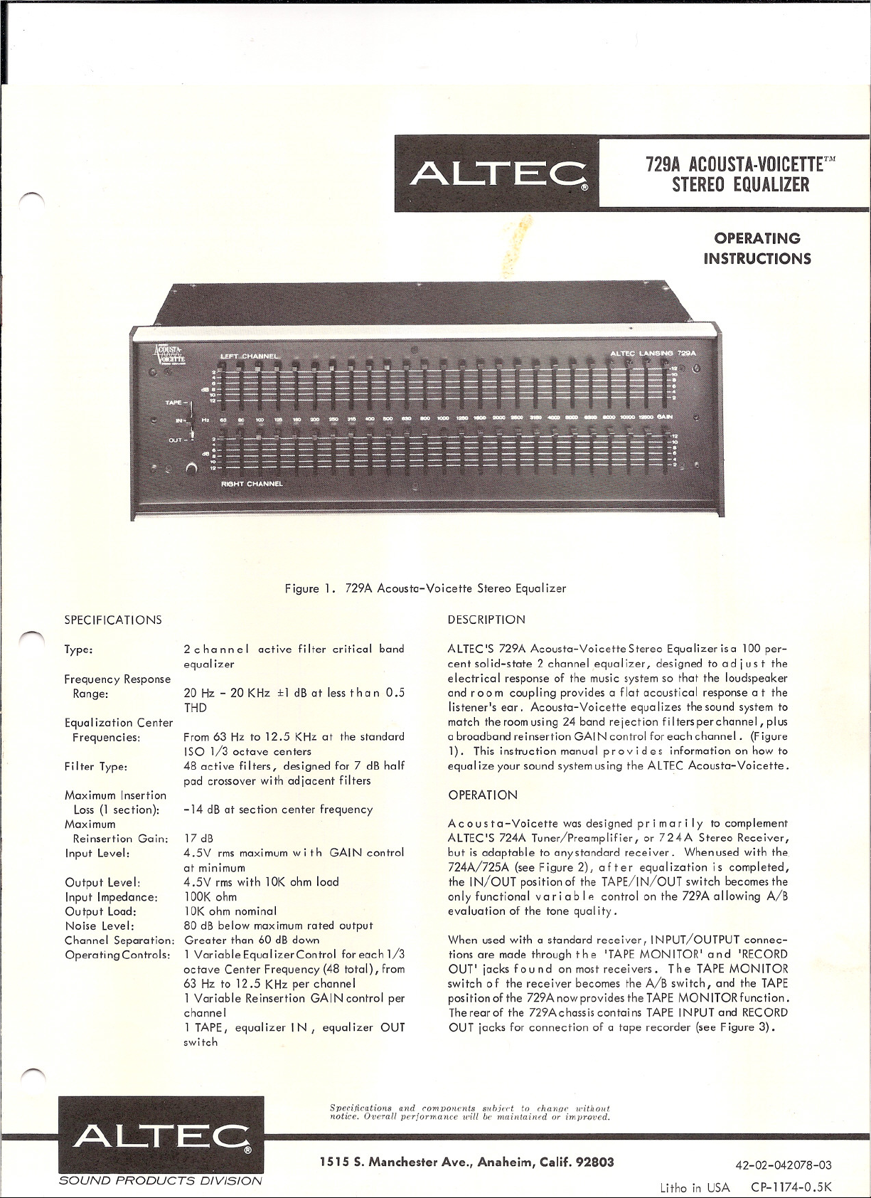
Figure 1. 729A Acousta-Voicette Stereo Equalizer
SPECIFICATIONS
Type:
Frequency Response
Range:
Equal ization Center
Frequencies:
Filter Type:
Maximum Insertion
Loss (1 section):
Maximum
Reinsertion Gain:
Input Level:
Output Level:
Input Impedance:
Output Load:
Noise Level:
Channel Separation:
Operating Controls:
2 c h ann e I active fi Iter critical band
equa Iizer
20Hz-20KHz ±1 dB at less than 0.5
THD
From 63 Hz to 12.5 KHz at the standard
ISO 1/3 octave centers
48 active filters, designed for 7 dB half
pad crossover with adjacent filters
-14 dB at section center frequency
17 dB
4.5V rms maximum with GAIN control
at minimum
4 .5V rms wi th 10K ohm load
lOOK ohm
10K ohm nominal
80 dB below maximum rated output
Greater than 60 dB down
1 Variable EqualizerControl for each 1/3
octave Center Frequency (48 total), from
63 Hz to 12.5 KHz per channel
1 Variable Reinsertion GAIN control per
channel
1 TAPE, equalizer IN, equalizer OUT
switch
DESCRIPTION
ALTEC'S 729A Acousta-VoicetteStereo Equalizerisa 100 per-
cent sol id-state 2 channel equa Iizer, des igned to ad jus t the
electrical response of the music system so that the loudspeaker
and room coupling provides a flat acoustical response a t the
listener's ear. Acousta-Voicette equalizes the sound system to
match the room using 24 band rejection filtersperchannel, plus
a broadband reinsertion GAl N control for each channel. (Figure
1). This instruction manual pro v ide s information on how to
equal ize your sound system using the AL TEC Acousta-Voicette.
OPERATION
A c
0 u s to -Voicette was designed p rim a r i I y to complement
ALTEC'S 724A Tuner/Preamplifier, or 724A Stereo Receiver,
but is adaptable to any standard receiver. When used with the
724A/725A (see Figure 2), after equalization is completed,
the IN/OUT positionof the TAPE/IN/OUT switch becomes the
only functional variabl" control on the 729A allowing A/B
evaluation of the tone quality.
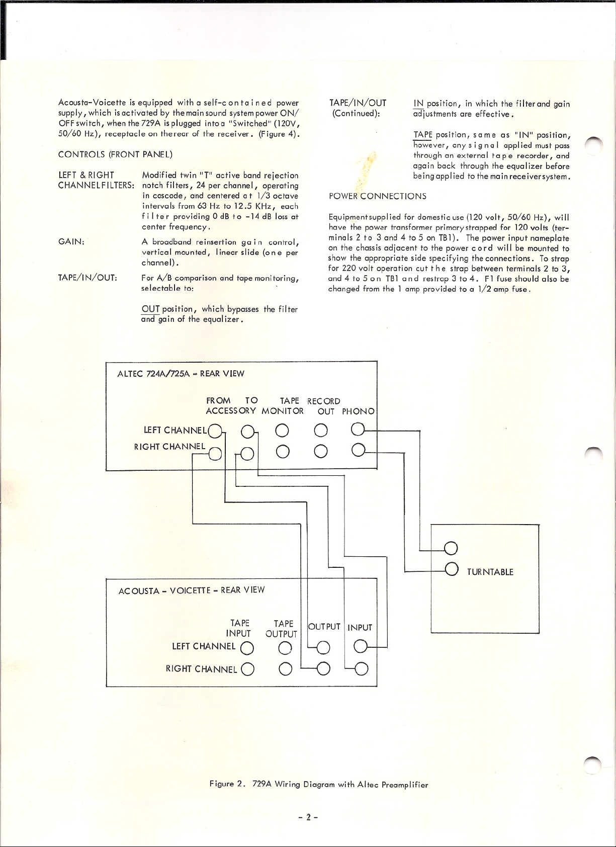
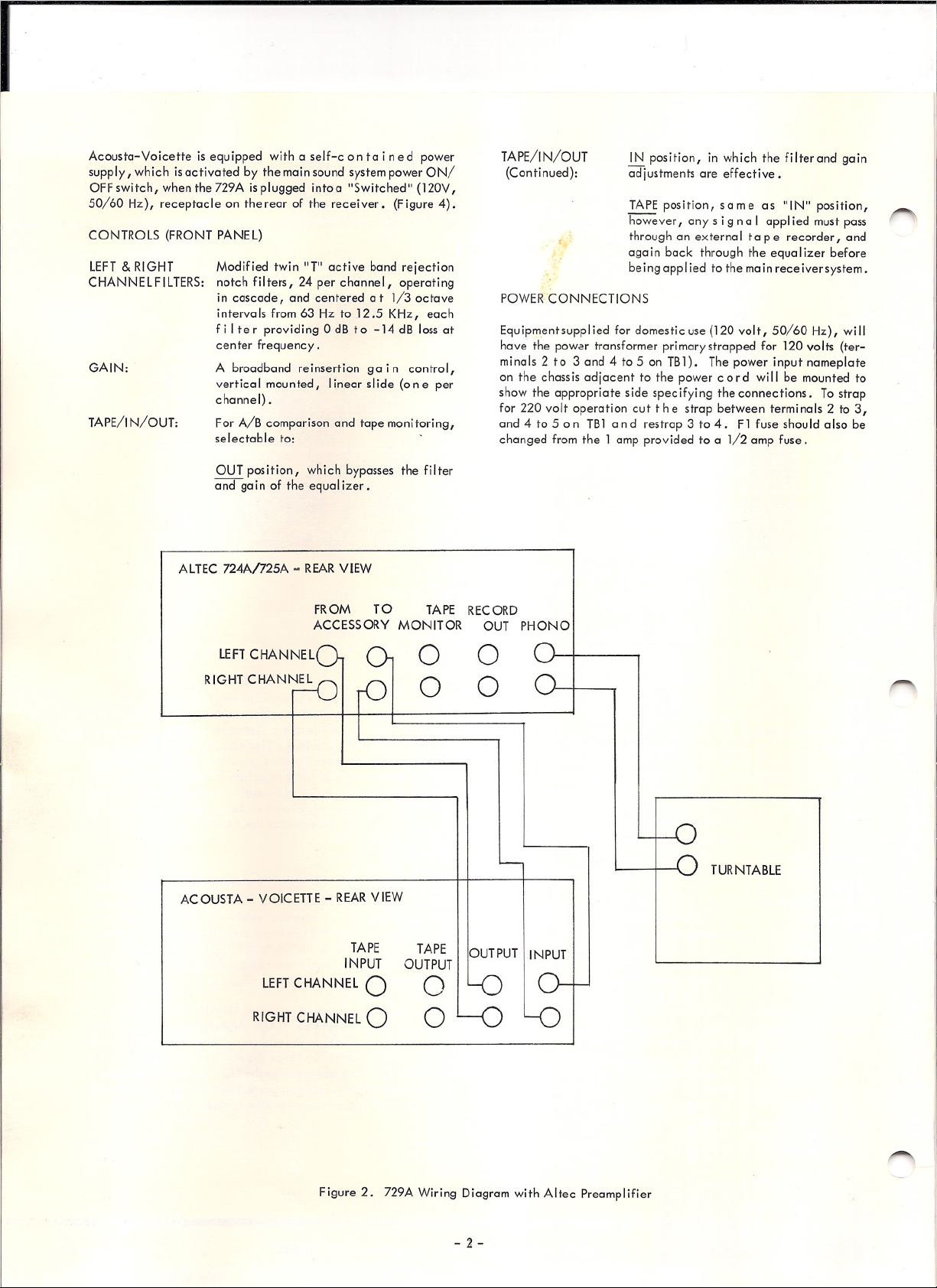
When used with a standard receiver, INPUT/OUTPUT connec-
tions are made through the 'TAPE MON ITOR I and 'RECORD
OUT' jacks found on most receivers. The TAPE MONITOR
switch of the receiver becomes the A/B switch, and the TAPE
position of the 729A now provides the TAPE MONITOR function.
The rearof the 729Achassis contains TAPE INPUT and RECORD
OUT jacks for connection of a tape recorder (see Figure 3).
Specifications and components sllbjed to chan{Jc without
notice. Ot'crall ]Jcrjonnancc will he
maintaitlf'd or im]Jun'cd.
ALT.EC
®
SOUND PRODUCTS DIVISION
1515 S. Manchester Ave., Anaheim, Calif. 92803
42-02-042078-03
Litho in USA CP-1174-0.5K
I
CONTROLS (FRONT PANEL)
Acousta-Voicette is equipped with a self-c 0 n ta i n e d power
supply, which is activated by the main sound system power ON/
OFF switch, when the 729A is plugged intoa "Switched" (120V,
50/60 Hz), receptacle on the rear of the receiver. (Figure 4).
POWER CONNECTIONS
Equipmentsupplied for domestic use (120 volt, 50/60 Hz), will
have the power transformer primary strapped for 120 volts (ter-
minals 2 to 3 and 4 to 5 on TB1). The power input nameplate
on the chass is ad jacent to the power cor d wi II be mounted to
show the appropriate side specifying the connections. To strap
for 220 volt operation cut the strap between terminals 2 to 3,
and 4 to 5 on TBl and restrap 3 to 4. F1 fuse should also be
changed from the 1 amp provided to a 1/2 amp fuse.
IN position, in which the filter and gain
adjustments are effective.
TAPE position, same as "IN" position,
however, any s i g n a I appl ied must pass
through an external ta p e recorder, and
again back through the equalizer before
be ing appl ied to the main receiver system.
TAPE/IN/OUT
(Conti nued):
Modified twin "T" active band rejection
notch filters, 24 per channel, operating
in cascade, and centered at 1/3 octave
intervals from 63 Hz to 12.5 KHz, each
f i I te r providing 0 dB to -14 dB loss at
center frequency.
A broadband reinsertion ga i n control,
vertical mounted, linear sl ide (0 n e per
channel) .
For A/B comparison and tape monitoring,
selectable to:
GAIN:
LEFT
& RIGHT
CHANNELFILTERS:
TAPE/IN/OUT:
OUT position, which bypasses the filter
and ga in of the equa Iizer •
ALTEC 724A/725A - REAR VIEW
FROM TO TAPE RECORD
ACCESSORY MONITOR OUT PHONO
o 0
o 0
TURNTABLE
ACOUSTA - VOICETTE - REAR VIEW
TAPE
INPUT
LEFT CHANNEL
0
RIGHT CHANNEL 0
TAPE
OUT PUT
o
o
OUTPUT IINPUT
Figure 2. 729A Wiring Diagram with Altec Preamplifier
- 2 -
I
CONTROLS (FRONT PANEL)
Acousta-Voicette is equipped with a self-c 0 n ta i n ed power
supply, which is activated by the main sound system power ON/
OFF switch, when the 729A is plugged intoa "Switched" (120V,
50/60 Hz), receptacle on the rear of the receiver. (Figure 4).
POWER CONNECTIONS
Equipmentsupplied for domestic use (120 volt, 50/60 Hz), will
have the power transformer primary strapped for 120 volts (ter-
minals 2 to 3 and 4 to 5 on TB1). The power input nameplate
on the chassis adjacent to the power cord will be mounted to
show the appropriate side specifying the connections. To strap
for 220 volt operation cut the strap between terminals 2 to 3,
and 4 to 5 on TBl and restrap 3 to 4. F1 fuse should also be
changed from the 1 amp provided to a 1/2 amp fuse.
IN position, in which the filter and gain
adjustments are effective.
TAPE position, same as "IN" position,
however, any s i g n a I appl ied must pass
through an external ta p e recorder, and
aga i n back through the equa Iizer before
be ing appl ied to the main rece iver system.
TAPE/IN/OUT
(Conti nued):
Modified twin "T" active band rejection
notch filters, 24 per channel, operating
in cascade, and centered at 1/3 octave
intervals from 63 Hz to 12.5 KHz, each
f i I te r providing 0 dB to -14 dB loss at
center frequency.
A broadband reinsertion g a i n control,
vertical mounted, linear slide (0 ne per
channel) .
For A/B comparison and tape monitoring,
selectable to:
GAIN:
LEFT
& RIGHT
CHANNELFILTERS:
TAPE/I N/OUT:
OUT position, which bypasses the filter
and gain of the equalizer.
ALTEC 724A/725A - REAR VIEW
FROM TO TAPE RECORD
ACCESSORY MONITOR OUT PHONO
o 0
o 0
TURNTABLE
ACOUSTA - VOICETTE - REAR VIEW
TAPE
INPUT
LEFT CHANNEL
0
RIGHT CHANNEL 0
TAPE
OUTPUT
o
o
OUTPUT I INPUT
Figure 2. 729A Wiring Diagram with Altec Preamplifier
- 2 -
 Loading...