

Page 1
FOR CAR USE ONLY/ NUR FÜR AUTOMOBILGEBRAUCH/ POUR APPLICATION AUTOMOBILE/ PARA
USO EN AUTOMÓVILES/ SOLO PER L’UTILIZZO IN AUTOMOBILE/ ENDAST FÖR BILBRUK/ ALLEEN
VOOR GEBRUIK IN DE AUTO/ ТОЛЬКО ДЛЯ ИСПОЛЬЗОВАНИЯ В АВТОМОБИЛЯХ
PDP-E802DSP
8 CHANNEL CLASS-D DSP POWER AMPLIFIER
EN
DE
FR
• OWNER’S MANUAL
Please read before using this equipment.
• BEDIENUNGSANLEITUNG
Lesen Sie diese Bedienungsanleitung bitte
vor Gebrauch des Gerätes.
• MODE D’EMPLOI
Veuillez lire avant d’utiliser cet appareil.
• MANUAL DE OPERACIÓN
Léalo antes de utilizar este equipo.
ALPINE ELECTRONICS MARKETING, INC.
1-7, Yukigaya-Otsukamachi, Ota-ku,
Tokyo 145-0067, JAPAN
Phone: 03-5499-4531
ALPS ALPINE EUROPE GmbH
Ohmstraße 4
85716 Unterschleißheim, Germany
Phone: 089-3242640
For contact information in your
respective country, please visit:
www.alpine-europe.com/distribution.html
• ISTRUZIONI PER L’USO
Si prega di leggere prima di utilizzare il
attrezzatura.
• ANVÄNDARHANDLEDNING
Innan du använder utrustningen bör du
läsa igenom denna användarhandledning.
• GEBRUIKERSHANDLEIDING
Lees deze aanwijzingen aandachtig
alvorens dit toestel te gebruiken.
• РУКОВОДСТВО ПО ЭКСПЛУАТАЦИИ
Прочтите настоящее руководство
перед началом использования
оборудования.
ALPINE ELECTRONICS OF AMERICA, INC.
1500 Atlantic Boulevard, Auburn Hills,
Michigan 48326, U.S.A.
Phone 1-800-ALPINE-1 (1-800-257-4631)
ALPINE ELECTRONICS OF AUSTRALIA PTY. LTD.
161-165 Princes Highway, Hallam
Victoria 3803, Australia
Phone 03-8787-1200
ALPS ALPINE ASIA CO.,LTD.
The 9th Towers, Tower B ,floor 24th 33/4 Rama 9 road
Huay Kwang, Huay Kwang
Bangkok, Thailand 10310
Phone: +66 2-090 9596 Ex.265
ES
IT
SE
NL
RU
Designed by ALPS ALPINE Europe GmbH
Page 2

Page 3
English
CONTENTS
WARNING................................................................................3
SERVICE CARE .......................................................................4
PRODUCT FEATURES ..........................................................5
ACCESSORIES ........................................................................6
INSTALLATION SEQUENCE ................................................ 7
HARDWARE CONFIGURATION .........................................8
Replacing Fuses....................................................................8
input configuration ......................................................... 10
PARALLEL MODE .............................................................. 10
WIRELESS MODULE .......................................................... 14
INSTALLATION .................................................................... 14
CONNECTOR PINNING .................................................... 14
PC CONNECTION .............................................................. 15
FACTORY settings ............................................................. 16
ALPINE SOUND LAB FOR PDP‑E802DSP ................... 17
ALPINE REMOTE CONTROL APP
FOR PDP‑E802DSP ........................................................ 26
USB CONNECTION FOR MUSIC PLAYBACK............ 27
WIRELESS STREAMING .................................................... 27
SYSTEM EXAMPLES .......................................................... 28
TROUBLESHOOTING ........................................................ 36
FIRMWARE UPDATE .......................................................... 37
SPECIFICATIONS ................................................................38
WARNING
Points to Observe for Safe
Usage
Read this manual carefully before using the system
components. They contain instructions on how to
use this product in a safe and effective manner.
Alpine cannot be responsible for problems
resulting from failure to observe the instructions in
this manual.
This symbol means important instructions.
WARNING
DO NOT OPERATE ANY FUNCTION THAT TAKES YOUR
ATTENTION AWAY FROM SAFELY DRIVING YOUR
VEHICLE.
Any function that requires your prolonged attention
should only be performed after coming to a complete
stop. Always stop the vehicle in a safe location before
Failure to heed them can result in serious
injury or death.
performing these functions. Failure to do so may result in
an accident.
KEEP THE VOLUME AT A LEVEL WHERE YOU CAN STILL
HEAR OUTSIDE NOISES WHILE DRIVING.
Excessive volume levels that obscure sounds such as
emergency vehicle sirens or road warning signals (train
crossings, etc.) can be dangerous and may result in an
accident. LISTENING AT LOUD VOLUME LEVELS IN A CAR
MAY ALSO CAUSE HEARING DAMAGE.
DO NOT DISASSEMBLE OR ALTER.
Doing so may result in an accident, fire or electric shock.
USE THIS PRODUCT FOR MOBILE 12V APPLICATIONS.
Use for other than its designed application may result in
fire, electric shock or other injury.
USE THE CORRECT AMPERE RATING WHEN REPLACING
FUSES.
Failure to do so may result in fire or electric shock.
DO NOT BLOCK VENTS OR RADIATOR PANELS.
Doing so may cause heat to build up inside and may result
in fire.
MAKE THE CORRECT CONNECTIONS.
Failure to make the proper connections may result in fire or
product damage.
USE ONLY IN CARS WITH A 12 VOLT NEGATIVE GROUND.
(Check with your dealer if you are not sure.) Failure to do so
may result in fire, etc.
BEFORE WIRING, DISCONNECT THE CABLE FROM THE
NEGATIVE BATTERY TERMINAL.
Failure to do so may result in electric shock or injury due to
electrical shorts.
DO NOT ALLOW CABLES TO BECOME ENTANGLED IN
SURROUNDING OBJECTS.
Arrange wiring and cables in compliance with the manual
to prevent obstructions when driving. Cables or wiring
that obstruct or hang up on places such as the steering
wheel, gear lever, brake pedals, etc. can be extremely
hazardous.
DO NOT SPLICE INTO ELECTRICAL CABLES.
Never cut away cable insulation to supply power to other
equipment. Doing so will exceed the current carrying
capacity of the wire and result in fire or electric shock.
3-EN
Page 4
DO NOT DAMAGE PIPE OR WIRING WHEN DRILLING
HOLES.
When drilling holes in the chassis for installation, take
precautions so as not to contact, damage or obstruct
pipes, fuel lines, tanks or electrical wiring. Failure to take
such precautions may result in fire.
DO NOT USE BOLTS OR NUTS IN THE BRAKE OR
STEERING SYSTEMS TO MAKE GROUND CONNECTIONS.
Bolts or nuts used for the brake or steering systems (or any
other safety‑related system), or tanks should NEVER be
used for installations or ground connections. Using such
parts could disable control of the vehicle and cause fire etc.
This symbol means important instructions.
CAUTION
HALT USE IMMEDIATELY IF A PROBLEM APPEARS.
Failure to do so may cause personal injury or damage to
the product. Return it to your authorized Alpine dealer or
the nearest Alpine Service Center for repairing.
HAVE THE WIRING AND INSTALLATION DONE BY
EXPERTS.
The wiring and installation of this unit requires special
technical skill and experience. To ensure safety, always
contact the dealer where you purchased this product to
have the work done.
USE SPECIFIED ACCESSORY PARTS AND INSTALL THEM
SECURELY.
Be sure to use only the specified accessory parts. Use of
other than designated parts may damage this unit
internally or may not securely install the unit in place. This
may cause parts to become loose resulting in hazards or
product failure.
ARRANGE THE WIRING SO IT IS NOT CRIMPED OR
PINCHED BY A SHARP METAL EDGE.
Route the cables and wiring away from moving parts (like
the seat rails) or sharp or pointed edges. This will prevent
crimping and damage to the wiring. If wiring passes
through a hole in metal, use a rubber grommet to prevent
the wire’s insulation from being cut by the metal edge of
the hole.
DO NOT INSTALL IN LOCATIONS WITH HIGH MOISTURE
OR DUST.
Avoid installing the unit in locations with high incidence of
moisture or dust. Moisture or dust that penetrates into this
unit may result in product failure.
Failure to heed them can result in injury or
property damages.
SERVICE CARE
SERIAL NUMBER:
INSTALLATION DATE:
INSTALLATION TECHNICIAN:
PLACE OF PURCHASE:
IMPORTANT
Please record the serial number of your unit in
the space provided here and keep it as a
permanent record. The serial number plate is
located on the rear of the unit.
For European Customers
Should you have any questions about warranty,
please consult your store of purchase.
For Customers in other Countries
IMPORTANT NOTICE
Customers who purchase the product with which
this notice is packaged, and who make this
purchase in countries other than the United States
of America and Canada, please contact your dealer
for information regarding warranty coverage.
About the software license of the product
The software installed in the product contains
open‑source software.
See the following Alpine website for details on
the open source software.
http://www.alpine.com/e/oss/download
Information on disposal of old electrical and
electronics equipment and batteries (applicable
for countries that have adopted separate waste
collection systems)
If you want to dispose this
product, do not mix it
with general household
waste. There is a separate
collection system for used
electronic products in
accordance with legislation that requires proper
treatment, recovery and recycling. Contact your
local authority for details in locating a recycle
facility nearest to you. Proper recycling and waste
disposal will help conserve resources whilst
preventing detrimental effects on our health and
the environment.
4-EN
Page 5

PRODUCT FEATURES
Pure Class D amplifier technology
Alpine’s PDP‑E802DSP features a complete digital audio chain. Once the analogue input signal is
converted to digital, the signal remains fully digital in the processing and amplification stage.
Smart high level input
The latest generation of factory car radios include sophisticated diagnosis capabilities. If a regular
amplifier is connected, errors maybe detected potentially leading to a shutdown of the radio’s outputs.
PDP‑E802DSP features incorporated dummy‑loads to overcome the related problems.
Start-Stop capability
The Alpine PDP‑E802DSP assures a constant internal power supply, even if the battery voltage drops
significantly during engine start.
Alpine Sound Lab for PDP-E80xDSP for Windows PC
A sophisticated software for setting EQ, Time Correction, Crossover and Gain. This tool was designed by the
ALPINE sound team with the needs of the audiophile in mind. Wired and wireless connection available.
Alpine Remote Control App for PDP-E80xDSP for iOS and Android for Windows PC
Recall presets, change sources and control the volume right from your smartphone.
Optical input and HD Audio Streaming
High quality sources are not only limited to S/PDIF compatible devices, HD Audio content can be
streamed directly to the amplifier (additional apps may be needed).
Realtime GAIN adjustment
You get immediate feedback in the Alpine Sound Lab for PDP‑E802DSP (PC software) if any input
channel starts clipping. You can then simply reduce the input gain of the affected channel to achieve a
perfect signal match.
Power Save Mode
The Power Save Mode is automatically entered along with the Auto‑Remote feature. The amplifier
permanently monitors the inputs and remains switched off if no valid audio signal detected. This does
significantly reduce the power in such standby state. Same for potentially connected further amplifiers.
Many modern vehicle’s factory radios are CAN controlled and their in‑built amplifiers may unnecessarily
enter/remain in ON state for a while, even if not at all in use. Conventional aftermarket amplifiers would
unnecessarily switch on a drain the battery in those cases. PDP‑E802DSP only turns on, if there is an
audio signal being detected at its inputs.
Parallel mode
With this setting you can select the desired channel pairs to enter parallel mode. This would on the one
hand reduce the number of independently available output channels, but on the other hand improve
the output’s damping behavior. It virtually shares the connected load among the two paralleled output’s
(ex. a connected 2Ω load would appear as 4Ω to each of the two paralleled outputs).
Freely configurable source routing
PDP‑E802DSP’s analog input signal processing allows an individual signal routing and mixing to
each output channel. Mixing levels can be selected by useful percentage preset values independent
for analogue, USB and Toslink sources. This makes it very easy to configure for instance a center
speaker signal by simply summing up the desired input signals.
Day and Night Theme for the app
Better adjustment to the ambient brightness.
5-EN
Page 6

ACCESSORIES
1. DSP Amplifier PDP‑E802DSP ................................................................................................ 1
2. Jumper
3. Power Harness 1,5m ................................................................................................................ 1
4. Speaker Output Harness ....................................................................................................... 1
5. RCA Input + Remote Harness .............................................................................................. 1
6. USB Connection Cable ........................................................................................................... 1
7. RJ11 Adapter for RUX‑Knob ................................................................................................. 1
8. RCA Adapter for Speaker Level In ...................................................................................... 6
9. Wireless Module (optional) .................................................................................................. 1
1 2 3
........................................................................................................................................ 5
x5
4 5 6
7 8 9
6-EN
Page 7
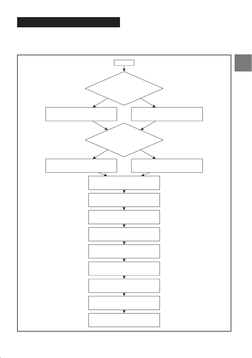
INSTALLATION SEQUENCE
Please follow the flowchart below when installing the
PDP‑E802DSP for the first time. Before completing the
installation, we recommend to update the
PDP‑E802DSP to the latest firmware.
Start
Parallel mode needed?
(2 Ohms, high power)
yes
no
Change jumpers according to
owner’s manual
Speaker Level Input?
yes
Change jumpers according to
owner’s manual
Amplifier is ready for installation
Connect all inputs and outputs
Make sure input power is low
Connect PC and start software
Set analogue routing
Use default setting
no
Use default setting
Connect power
Startup amplifier
Output settings
(Impedance, Parallel Mode)
Make sound setting
7-EN
Page 8

HARDWARE
SENSITIVE DEVICES
CONFIGURATION
This product uses semiconductors that can be
damaged by electrostatic discharge (ESD).
ATTENTION
OBSERVE PRECAUTIONS
FOR HANDLING
ELECTROSTATIC
When handling, care must be taken so that the
devices are not damaged. Damage due to
inappropriate handling is not covered by the
warranty. The following precautions must be taken:
• Use a conductive wrist strap attached to a good
earth ground.
• Always discharge yourself by touching a
grounded bare metal surface or approved
anti‑static mat before picking up an ESD –
sensitive electronic component.
• Use an approved anti‑static mat to cover your
work surface.
1. Remove the side panel (USB side) as shown by
releasing the indicated screws.
3. Release the indicated screws in order to remove
the digital board.
4. Flip over the digital board.
5. Now you can reach all jumpers and the fuses.
REPLACING FUSES
The main fuses are located under the bottom
cover. Therefore, you must remove the side panels.
2. Slide the bottom cover out of it’s guards.
8-EN
Use always the same ratings in case you have to
replace them. If the fuses are frequently tripped,
make sure to eliminate the cause before replacing
the fuses
Page 9
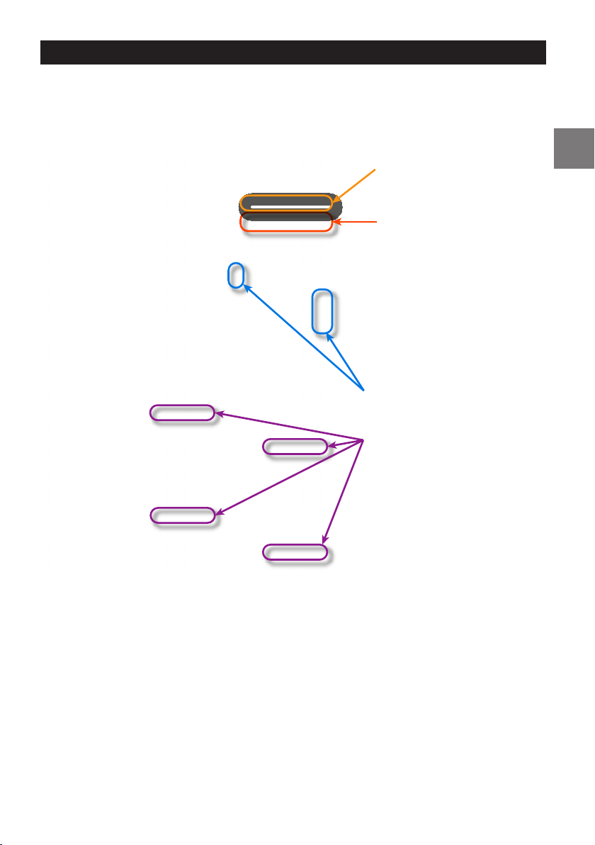
JUMPER LOCATIONS
(FACTORY DEFAULT=connected)
Power
Connector
Speaker
Connector
Input
Connector
100Ω Load for Factory Unit
(see page 10)
J32/J33CH1/2
J34/J35CH3/4
J36/J37CH5/6
100Ω load in High mode if open
High/ Low Power Input
(see page 10)
J1/J4Channel 1
J9/10Channel 2
J12/J13Channel 3
J14/J15Channel 4
J19/J20Channel 5
J21/J22Channel 6
AC Detection
(see page 24)
Parallel Mode
(see page 10)
J7+J16 for Channel 1+2
J8+J17 for Channel 3+4
J25+J28 for Channel 5+6
J24+J27 for Channel 7+8
DC Detection
}
capable
AC Detection
}
capable
9-EN
Page 10

INPUT CONFIGURATION
Set the jumpers accordig to your connection
method to the headunit.
High Level inputs (speaker line)
Important:
For setting the High/Low level jumpers make sure
the power is disconnected.
To change the position of a jumper, it has to be
removed by pulling it straight up. Make sure that
the jumper is reinserted properly and all pins are
fully inserted.
Default setting is low level input.
PARALLEL MODE
Depending on the system setup there are two
options for driving 2Ω loads (e.g. subwoofer).
Load Selection for High Level Inputs
If PDP‑E802DSP is replacing an OEM amplifier,
which has been driven by the factory headunit’s
speaker outputs, it is often the case that those
outputs are configured in so called line driver
mode. (DC bias voltage without signal vs. GND
is approx. 3V.)If so, it may be required to set the
corresponding PDP‑E802DSP speaker inputs’
impedance to 100Ω by removing the yellow
jumpers in order to prevent the headunit from
shutting down its speaker outputs.
Low Level inputs (RCA)
Option 1:
single output channel.
Advantage:
channels. Up to 100W (RMS) into 2Ω.
Side effect: The maximum output power is also
being reduced for all other channels.
Option 2: The 2Ω driver is being connected to a
paralleled output channel.
Conditions: Output CH1+2 or CH3+4 or CH5+6 or
CH7+8 need to be paralleled.
Advantage: Better damping factor for the
connected 2Ω load.
Side effect: The total number of output channels
will be reduced.
Note: Please do not to set more than 4 channels
in parallel mode to avoid any overheating. This
feature is intended for driving low impedance
woofers of factory systems.
The 2Ω driver is being connected to a
No reduction of available output
10-EN
All channels are in standard mode in the above
image. This is the default setting.
Page 11
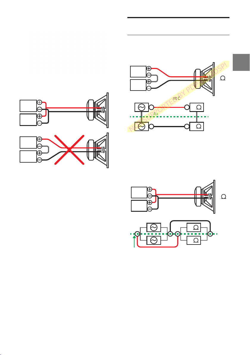
Example for parallel mode on channels 7+8:
BRIDGE MODE VS. PARALLEL
MODE
Bridge Mode
NOT SUPPORTED BY PDP‑E802DSP!
This connection equals a straight short and may
break your amplifier.
Note: Connections are not done as in
regular bridged mode!Example for parallel
mode on channels 7+8:
CH7
CH8
CH7
CH8
Workflow for parallel mode:
1. Disconnect the power harness.
2. Do the Hardware settings inside the amplifier.
3. Connect the speakers in parallel mode to the
speaker harness (do not yet connect to the
amplifier).
4. Connect the power cable and start the amp.
5. Do the software settings and store them on any
preset.
6. Switch off the amplifier.
7. Connect the speaker harness to the amplifier
8. Turn on the amplifier.
CH1
4
CH2
The Equivalent Circuit
2
Axis of Symmetry
2
•
Output Channels are connected in series
• Effective channel load impedance
becomes50% of the actually connected load.
• CH1/CH2 signals could be arbitrary and will
automatically sum up (mono mix)
Parallel Mode:
CH1
2
CH2
The Equivalent Circuit
4
4
Axis of Symmetry
• Channels are connected in parallel and thereby
share the current 50:50.
• Effective channel load impedance
becomes200% of the actually connected load.
• CH1/CH2 signals have to be 100% identical and
properly paralleled closest possible to each
output stage as otherwiseyou may break your
amplifier.
11-EN
Page 12

CONNECTIONS
Caution: Carrying out the following steps will
require special tools and technical knowledge.
To avoid connection mistakes and/ or damage
ask your dealer for assistance. We recommended
the installation should be done by an ALPINE
authorized dealer.
Fig. 2: Audio Connections
Please refer to Fig. 2
1 Battery Lead Connector
2 Speaker Output Connector
Im
portant: We highly recommend doing the
general settings in the Alpine Sound Lab for
PDP‑E802DSP before the first start up (see
“Amplifier Setting Tab” on page 23). An
incorrect setting may destroy your tweeters.
Make sure the source volume is set to 0 when
starting up the PDP‑E802DSP for the first time.
3 Input Connector
RCA Input Channels 1 - 6
4-9
6-channel input (low level), for connection to
signal sources with any output level. Please
configure high or low power using the jumpers
inside the amplifier. Default setting is low level.
Use the correct cable (RCA/cinch cable) to
connect these inputs to the pre‑amplifier / low
level outputs of your head unit. Each input can
be assigned to any output using the Alpine
Sound Lab for PDP‑E802DSP software. The
autosensing function has also to be
configured within this app.
0 Remote Input
The remote input line shall be used for
switching the amplifier on/off. It is not
recommended controlling the remote input via
the ignition switch as this may cause pop noise
during turn on/off.
The Auto‑Remote feature needs to be
configured in the Alpine Sound Lab for
PDP‑E802DSP software.
! Remote Output
The remote output line can be used
for switching on/off further amplifiers.
@Preset Toggle
When positive trigger is applied, PDP‑E802DSP
will switch to preset 6 (Trigger voltage =
2.5VDC or more).
# Pre-Out Jack
This is an ideal output for driving a separate
subwoofer amp. The 1‑channel RCA output is fully
processed and a straight “copy” of speaker output
channel 8. An optionally connected amplifier
should be able to handle input signals of up to 2V
RMS. We do recommend connecting high quality
amplifiers with differential RCA input/s (ground
isolated) in order to avoid unwanted noise.
1 2 3
$-u Output Channels 1 - 8
Amplifier outputs that are connected to the
speakers. The minimum impedance per
channel is 2Ohms. Please configure your
system impedance using the Alpine Sound Lab
for PDP‑E802DSP (See “2 Speaker Load
Setting” on page 23).
Never connect any of the speaker cables with
the chassis ground as this will damage your
amplifier and your speakers. Make sure that all
speakers are connected in phase.
4
5
6
7
8
9
0
!
@
#
$
%
^
&
*
(
)
=
q
w
e
r
t
y
u
i
o
12-EN
Page 13

i Battery Cable (+)
Be sure to add an External Fuse (e.g. Fuse Block,
Circuit Breaker) to the battery lead no further
than 30cm from the battery’s positive (+)
terminal. This fuse will protect your vehicle’s
electrical system in case of a short circuit.
Appropriate fuse value requirement: 60 A fuse.
Ground Cable (-)
o
The ground cable should be connected to a
common ground reference point (this is located
where the negative terminal of the battery is
grounded to the metal body of the vehicle) or to
a prepared metal location on the vehicle chassis
i. e. an area which has been cleaned of all paint
residues.
Fig. 3: Other Connections
Please refer to Fig. 3
p [ ] \ a s
p Status Indicators
Red: The LED indicates:
• Startup and shutdown process
• Analogue input clipping
• Thermal/ Power protection triggered
• Toslink not locked (if source set to Toslink)
Green:
• The amp is switched ON and in normal
operation.
• Indicates DSP configuration OK at startup
• Flashing: communication with PC/ Phone
Yellow: The amp is connected to a computer by
USB or Wi‑Fi.
[ Optical Digital Input
Optical input to connect S/PDIF sources. The
sampling rate for this input must be between
12 and 96kHz. The input signal is automatically
converted to the internal sampling rate.
You can select the Digital input by using the
remote app.
Caution: The signal of a digital audio source
normally does not contain any information
about the volume level. In this case the amp will
perform at maximum ouput level. This may
damage your speakers. It is recommended to
use the ALPINE remote app or the wired
RUX‑Knob.
Note: The Alpine PDP‑E802DSP amp can only
handle uncompressed digital stereo signals in
PCM format with a sampling rate between
12kHz and 96kHz. No Dolby coded signals.
]
Micro USB Connection
Connect your personal computer or smart
phone. See “PC CONNECTION” on page 15 and
“USB Connection for Music Playback” on page
27.
The required PC software (Alpine Sound Lab for
PDP‑E802DSP) to configure this amplifier can be
downloaded from your local Alpine website.
Please note: It is not possible to connect any
USB storage devices.
\
USB Connection
For future applications.
a
Remote Volume Control
This input is designed for the Alpine RUX‑Knob
which allows you to adjust the main volume or
subwoofer volume. The functionality must be
defined in the „Amp Settings“ within the PC app.
s
USB Port for Wireless Module
Connect the optional wireless module using the
supplied USB cable. The wireless module will
enable the wireless connection of a PC or smart
phone using the respective apps. It can also be
13-EN
Page 14
used for the remote app or streaming audio
1
content.
WIRELESS MODULE
The optional module WAD‑PDP1 is made for
wireless control by Alpine Sound Lab for
PDP‑E802DSP and for the Alpine remote app
(available in appstores for Android and IOS). You
can also stream audio files from your smartphone
to the amplifier.
1 23
1 Micro USB connection to amplifier
2 Status LEDs
Green: On
Red: Data transfer
3 Reset
Apply a jumper for 4 seconds to reset.
INSTALLATION
Due to the high power output of the PDP‑E802DSP
considerable heat is produced when the amplifier
is in operation. For this reason, the amplifier should
be mounted in a location which will allow for free
circulation of air, such as inside the luggage area.
For alternative installation locations, please contact
your authorized Alpine dealer.
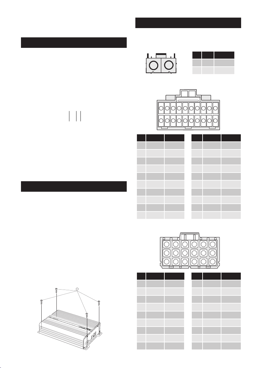
1. Using the amplifier as a template, mark the four
screw locations.
2. Make sure there are no objects behind the
surface that may become damaged during
drilling.
3. Drill the screw holes.
4. Position the PDP‑E802DSP over the screw holes,
and secure with four self‑tapping screws.
CONNECTOR PINNING
View from cable side.
Power Harness
PIN Color Function
4
14
6
5
16
15
7
10
11
12 18
1 Red Battery +
2 Brown Ground -
9
8
7
10
19
18
17
20
16
13
17
14
15
10 White Ch. 6 -
11 Black Ch. 6 +
12 Black Ch. 5 +
13 White Ch. 7 -
14 Black Ch. 7 +
15 White Ch. 8 -
16 Black Line Out -
17 Red Line Out +
18 Black Ch. 8 +
2
1
Input Connector
3
1
2
13
11
12
PIN Color Function PIN Color Function
1 Black Ch. 1 Ground 11 White Ch. 1 Signal
2 Black Ch. 2 Ground 12 Red Ch. 2 Signal
3 Black Ch. 3 Ground 13 White Ch. 3 Signal
4 Black Ch. 4 Ground 14 Red Ch. 4 Signal
5 Black Ch. 5 Ground 15 White Ch. 5 Signal
6 Black Ch. 6 Ground 16 Red Ch. 6 Signal
7 NC 17 NC
8 NC 18 NC
9 White/Blue PresetToggle 19 NC
10 Blue/ White Remote Out 20 Blue/ White Remote In
Output Connector
1
4
2 8
5
6
3 9
PIN Color Function PIN Color Function
1 White Ch. 1 -
2 Black Ch. 1 +
3 White Ch. 2 -
4 White Ch. 3 -
5 Black Ch. 3 +
6 Black Ch. 2 +
7 White Ch. 4 -
8 Black Ch. 4 +
9 White CH. 5 -
14-EN
Page 15

PC CONNECTION
Minimum system requirements:
• Windows 10
32 and 64bit systems are supported
• 1,2Ghz; 1GB of RAM; 1GB of HDD space
• Latest .NET Framework (v 4.7.1 or higher)
• Minimum Display resolution: 1280x800
Software Installation:
You can download the Alpine Sound Lab for
PDP‑E802DSP software and the device driver
from your local Alpine website. The file can be
found in the support section.
The website will also contain short video clips
explaining the process step‑by‑step.
• Download the installation files
• Unpack the zip file
• Run the setup wizard
Screenshots from Windows Installation Process:
1
3
4
5
2
Caution:
It is highly recommended to set the volume of
your car source to minimum position during the
first start‑up. Additionally, no devices or
speakers should be connected to the amplifier
until general settings in the Alpine Sound Lab
for PDP‑E802DSP software have been made.
Especially when the PDP‑E802DSP is used to
drive a fully active speaker system. Wrong
settings can destroy your tweeters right away.
15-EN
Page 16
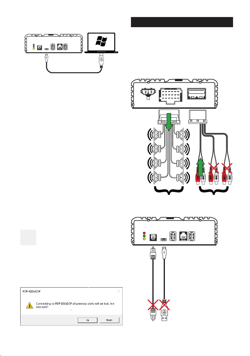
Connect your PC to the PDP-E802DSP:
• Connect your PC with the supplied micro
USB cable.
USB RC WIFI
OPT IN
PROT
STAT
PC
LINK
•
If you haven’t done so, connect power to
the PDP‑E802DSP. If the amplifier is not
switched on when the PC connection is
established, the PDP‑E802DSP will go to
the ‘update mode’.
• Start the software by double clicking the
Alpine Sound Lab for PDP‑E802DSP Icon
on your PC.
• To activate communication to the
PDP‑E802DSP simply press the power icon.
The power icon will also change from
being grey to being blue
FACTORY SETTINGS
• Input = RCA
• No parallel mode, 8 straight channels
• Input channels 1+2 linked to all output channels
• Analogue input source active
• Remote on by wire
• Highpass for all channels to protect speakers
POWER SUPPLY SPEAKER OUTPUT INPUT
Not Connected
Connected
Select „Yes“ in the pop‑up window. The DSP amp
is now ready for the system configuration to be
started.
16-EN
PROT
STAT
LINK
All channels are
feed with the
signal from
input 1+2.
OPT IN
PC
USB RC WIFI
By default only
channel 1+2 are
active.
Page 17
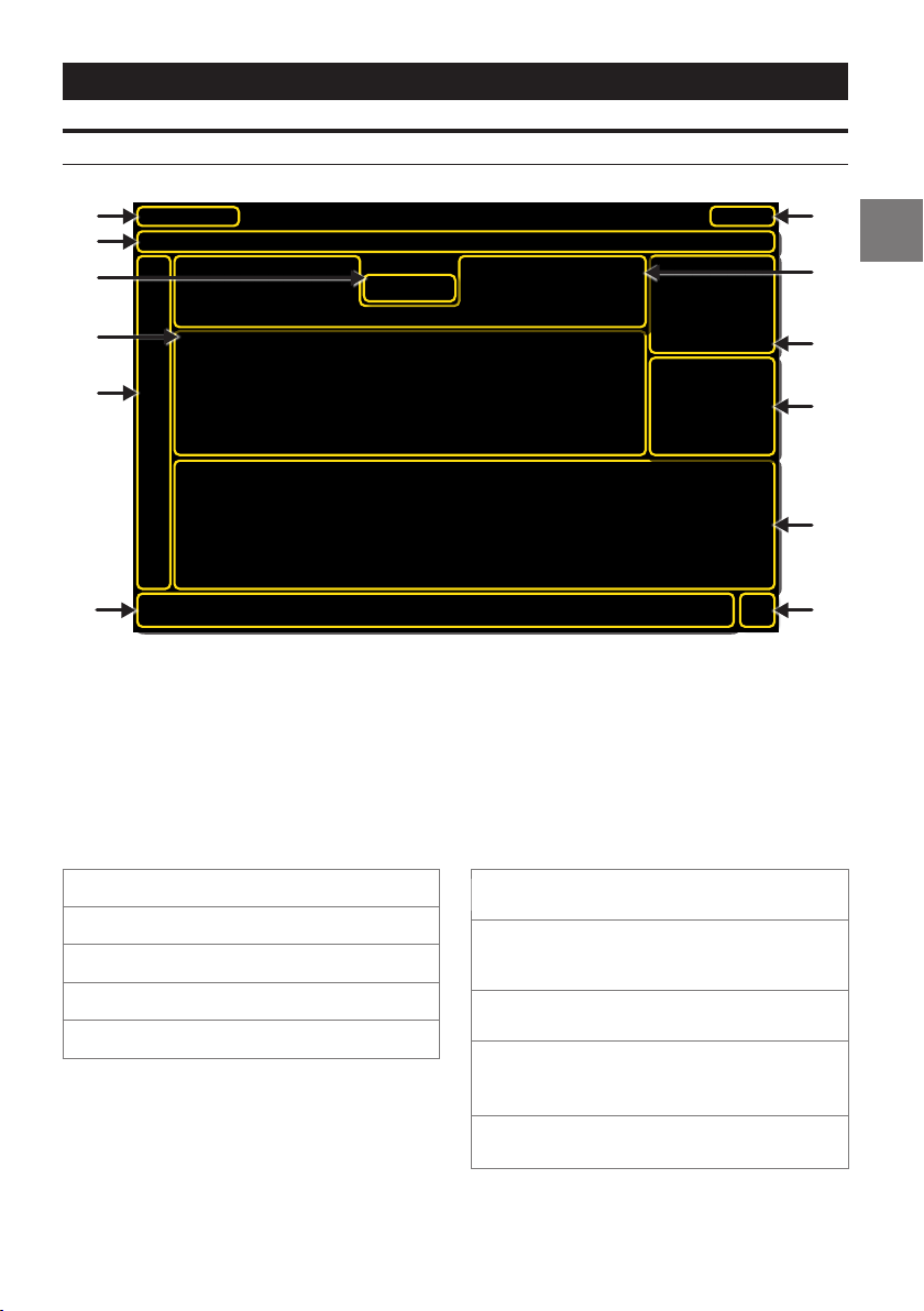
ALPINE SOUND LAB FOR PDP-E802DSP
7
8
9
0
!
@
Tuning Tab
1
2
3
4
5
6
1 Status Bar
2 Preset Bar
3 Source Selection
4 Graphical Representation of Settings
5 Channel Bar
6 Tab Bar
1 Status Bar
Red: Clipping on analogue input
Red: Clipping on speaker output
Battery status: Blue=OK; Red = Low
Temperature: Blue=OK; Red = Overheat
Short circuit on an output line
7 Connection Bar
8 Crossover Settings
9 Master/ Sub Volume Settings
0 Channel Gain and Time Correction Settings
! Equalizer Settings
@ ON/OFF Switch (starts PC connection)
2 Preset Bar
On: Preset selected
Off: Preset not selected
DSP Icon
Blue: Memory and current settings
are the same.
Grey: Memory saved but current
settings are different.
Lock Icon
Blue: You are the creator of the
settings and have full access.
Red: Settings are secured, you have
only limited access.
17-EN
Page 18
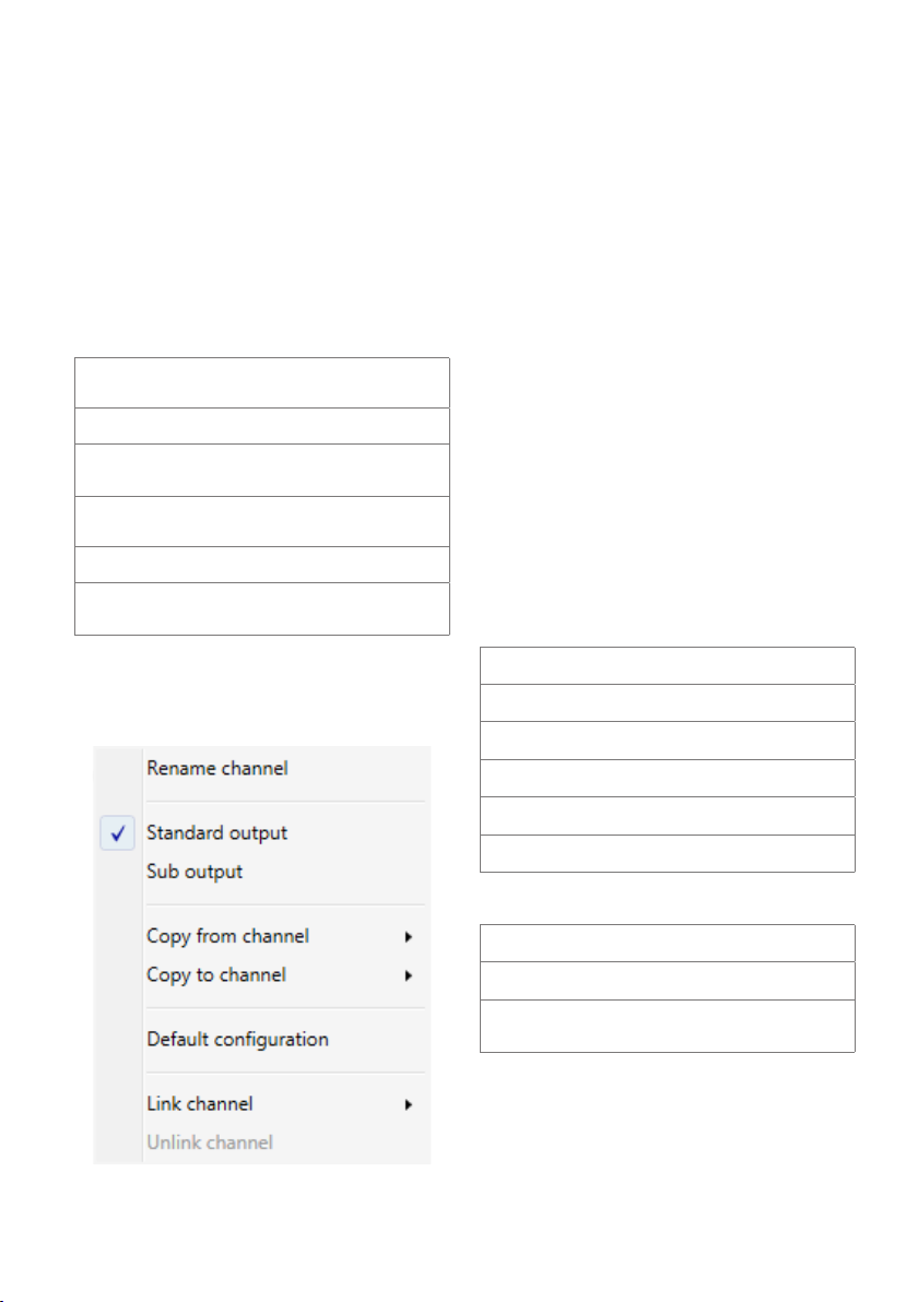
3 Source Selection
RCA (Analogue)
Optical (Digital)
USB
4 Graphical Representation of Settings
5 Channel Bar
LED Ring
Off: Channel not selected
Blue: Channel selected
Yellow: This channel is linked to the
selected channel.
Speaker Icon
Grey: Channel muted
Blue: Channel active
Orange: Channel configured as subwoofer,
subwoofer level control is active.
Channel Settings:
A right click on a speaker icon will show a
context menu with the options described
below:
channels will only be valid during the
current session.
Standard output:
The channel is linked to the master volume
controller.
Sub output:
The channel is linked to the subwoofer volume
controller.
Copy from channel:
You can copy the settings to the selected
channel.
Copy to channel:
Allows to transfer the settings to the selected
channel.
Default configuration:
Reset the channel to default. All settings are
deleted.
Link channel:
You can link 2 channels. All settings will be
copied to the linked channel. This is a common
way for dual subwoofers.
6 Tab Bar
Tuning tab
Input tab
Time correction tab
Rename channel:
All channels can be renamed, like FL Mid‑High,
Sub 1 etc. Be aware that the labels of the
18-EN
Overview tab
Amplifier setting tab
App setting tab
7 Connection Bar
On when wireless connection is established.
On when PC is connected via USB.
On when data is being transferred to the
PDP‑E802DSP.
Page 19
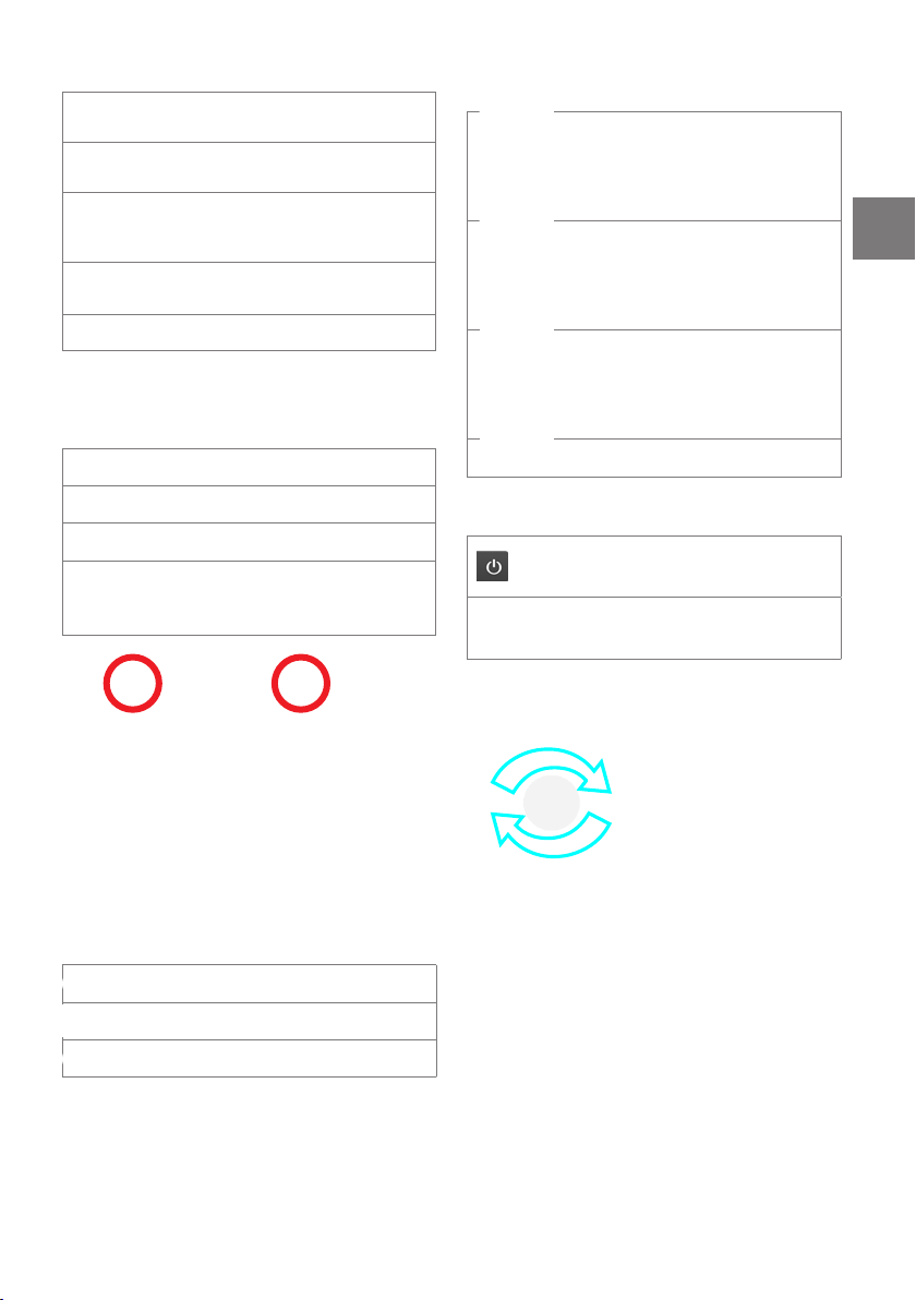
8 Crossover
Selection of crossover
frequency
Slope selection
(0 up to ‑30 dB/Oct. possible)
Filter characteristics
(Butterworth, Bessel,
Chebyshev)
Slider bar for quick crossover
selection
Crossover on/ off
9 Master/ Subwoofer Volume Setting
Master volume and level control subwoofer
channels.
Volume settings are locked.
! Equalizer Settings
30 Band Parametric EQ for the selected channel.
Gain Setting
+ 10dB/ ‑30dB
Center Frequency Setting
Q Factor Setting
1 (wide) ‑ 15 (narrow)
Select equalizer on/ off.
Blue: All channels are active.
Grey: All channels are muted.
On: Remote volume knob enabled (either
Master or Sub). Optional RUX‑KNOB
required.
0 Volume/ Delay Setting
Gain, time delay and phase inversion for the
selected channel.
Select channel muting on/ off.
Select phase inversion on/ off.
Select channel time delay on/ off.
@ ON/OFF Switch (starts PC connection)
Off: no connection between PC and
amplifier.
On: connection between PC and amplifier
established.
Adjustment of the rotary controllers
a) by mouse b) by cursor keys
Unused Channels:
• We recommend to use all available channels, i.e.
by using the parallel mode.
• When this is not possible, set the unused channel
to maximum attenuation (‑∞dB). This will help to
avoid wrong tripping of any protection mode.
19-EN
Page 20
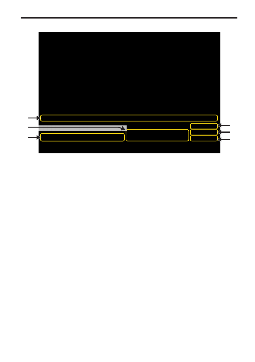
Input Tab
1
2
3
4
5
6
1 Gain Settings (-6dB - +12dB)
For a perfect input sensitivity setting to your
audio source check the following steps.
1. Don’t connect any amplifiers or loudspeakers
to the outputs of the ALPINE PDP‑E802DSP
during this setup.
2. Make source input connections
3. Do the jumper settings (high or low power, AC/
DC Detection, input load)
4. Turn on the amplifier
5. Adjust the source volume to 90% of the max.
Volume and playback a 1 kHz test tone (0dB)
via CD drive.
6. If the PROT LED already lights up, decrease the
input sensivitiy within the app until the PROT
LED turns off.
With this setting you are matching your source
to the amplifier. Higher gain does not mean
higher output power.
Note: the gain setting adapts the source volume
to the input of the amplifier. It does not set the
amplification factor. Suggested gains listed in the
table on next page.
2 Extra Gain
When the digital source appears not as loud as
other sources, the gain can be raised by using this
setting. Depending on the mastering of the source
material, there is risk of clipping when the Extra
Gain was raised.
3Enable Inputs
With this menu you can enable/ disable the
inputs of your amplifier.
4 Analogue Routing
With this matrix you can setup which input
channel is routed to which output channel in
percent. Using this method, you can simply
create a virtual center channel by applying 50%
left signal and 50% right signal.
Every channel should have 100% signal in total
for a proper use.
5 USB Routing 6 Toslink Routing
20-EN
Page 21
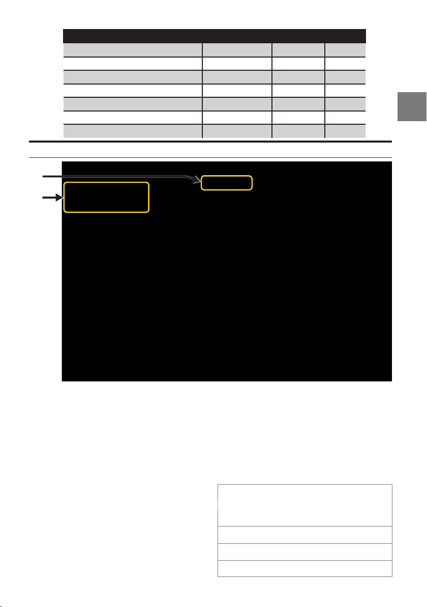
Headunit Connection Input Configuration Yellow Jumper Input Gain
Pre Out 2V Low plugged 0dB
Pre Out 4V Low plugged
Headphone out 500mV Low plugged +12dB
BTL Speaker Out (25W@4 Ohms) High plugged 0dB
Single Ended Speaker Out (6W@4 Ohms) High plugged +6dB
Line driver mode (for driving OEM amplifier) High removed +6dB
OEM Amplifier output (80W@4 Ohms) High plugged
Time Correction Tab
1
2
‑6dB
‑6dB
The time correction allows individual adjustments
for each speaker output to align the different
distances of each speaker relative to the listener’s
position inside the cabin.
Adjustments can be done for level, delay and phase
(0°/180°)
1 Assistance for time delay adjustment
A very accurate automatic time delay calculator
is built directly into the app.
To begin this setup, you have to measure the
physical distance of each speaker in the system
that has been assigned to an output channel.
Verify that your measurement value is correct.
Assign each speaker location to an output
channel. Enter the measurement of each
speaker’s distance to the driver’s seat headrest.
When all values have been entered simply press
the “APPLY” button to store these measurements
into each output channel the PDP‑E802DSP.
The rotary knobs can still be used to make even
finer adjustments if required.
2 Delay Setting
Allows adjustment of each independent output
channel audio signals to compensate for the
differences of poor speaker placement, relative
to the driver’s seating position in vehicles.
For the selected channel volume, delay setting
and Phase inversion 180° can be adjusted.
The group selection allows you to
create up to 4 different delay
groups. Changes will affect all
channels allocated to the group.
Channel muting on/ off
Phase inversion on/ off
Channel delay on/ off
21-EN
Page 22

Overview Tab
This screen visualizes the response curve(s) of the
selected user adjustments of crossover, EQ, TCR and
level for each output channel.
The parameters and channels to be reflected in the
visualization can be selected in the upper screen
area by toggling the selection boxes.
No channel information selected.
All settings are shown in the graphic
display (EQ, crossover, level).
Only crossover graphic is shown.
Only EQ settings of the selected
channel are shown.
22-EN
Page 23
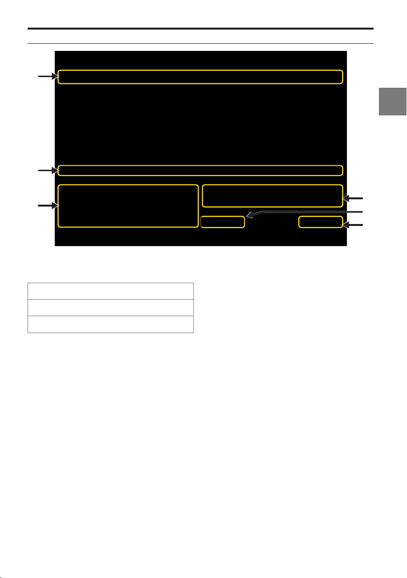
Amplifier Setting Tab
1
2
3
4
6
5
1 Channel Status
The status of each channel is shown by the three
indicators below.
Red: Short circuit on an output line
Red: Clipping on speaker output
Battery status: Blue=OK; Red = Low
2 Speaker Load Setting
You need to select the speaker load being
connected to each output for power supply
matching.
Connecting lower impedance loads (ex. 2Ω) will
result in an appropriate internal voltage
adjustment. In case of mismatches, the
following protection mechanisms may
automatically apply:
1. The amplifier will reduce the output power.
2. The amp shuts down to safe mode. The amp will
only recover after reboot (off/on). Impedance
settings are to be carefully reviewed in such
case.
3 Parallel Mode
With this setting you can select the desired
channel pairs to enter parallel mode. This would
on the one hand reduce the number of
independently available output channels, but
on the other hand improve the output’s
damping behavior. It virtually shares the
connected load among the two paralleled
outputs (ex. a connected 2Ω load would appear
as 4Ω to each of the two paralleled outputs).
See page 10 for details.
4 System Monitor
This section allows to check the battery voltage
of the vehicle and the temperature of the
amplifier.
5 Speaker Test
In order to protect your equipment from wrong
connections, the PDP‑E802DSP checks the
impedance of all speakers. If you think there is
a mis‑detection, i.e. all wirings etc. are correct,
switch off the “Speaker Test” feature.
6 Live Monitor
This tool allows you to monitor the average
temperature and voltage over a period of 1, 3 or
5 minutes.
23-EN
Page 24
3
4
1
2
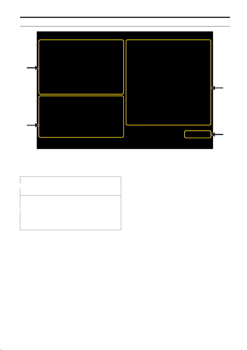
Application Setting Tab
1 DSP Status
This section shows the serial number of the
amplifier and the firmware version.
It is possible to delay switching on
and off the amplifier between 1s
and 10s.
The Autoremote feature allows to
switch on the amplifier by detection
of an audio signal. This may help in
cars where no amplifier turn on
signal is available. Options: OFF
(default), AC, DC
Autoremote OFF:
The PDP‑E802DSP will be switched on by
the remote wire.
Time ON:
Here you set the duration of the input signal to
be continuously detected above the threshold
limit prior to turning ON.
Threshold ON:
Here you set detection signal level for turning ON.
Time OFF:
Here you set the duration of the input signal to
be continuously detected below the threshold
limit prior to turning OFF.
Autoremote AC detection:
In this mode, the PDP‑E802DSP will detect an
audio signal from a source that is connected to
channels 5+6. Jumpers J2, J3, J5, J6, J38 must be
connected.
24-EN
Threshold OFF:
Here you can set detection signal level for turning
OFF.
Note:
The Threshold ON value should be always be
bigger than Threshold OFF.
Page 25

:
Tech Tip
If the amp is connected by USB wire and turns off
during the autoremote settings the amp falls in
Update mode. To restart the amp you have to
disconnect the USB and start the amp by cycling
power OFF/ON.
If AC dectection needed don´t forget to do the
jumper settings on PCB.
Autoremote DC detection:
The amp is checking, if there is an at least 3V(DC)
bias voltage provided from the installed source
unit. If so, the amp turns on.
The DC voltage will only be detected on
channels 1+2.
:
Tech Tip
The wired remote line is also working in parallel
to the DC detection.
2 Alpine Sound Lab for PDP-E802DSP Status
Here you can find information regarding
software and build versions.
Depending on the environment the
Alpine Sound Lab for PDP‑E802DSP
is used in, you can choose between
a day and a night theme.
Here you can select your preferred
language for the Alpine Sound Lab
for PDP‑E802DSP.
3 Wireless Status and Settings
This section allows to check the configuration of
the wireless adapter WAD‑DPD1.
Basic settings can also be made. Usually the
default configuration will work fine.
25-EN
Page 26

ALPINE REMOTE CONTROL APP FOR PDP-E802DSP
In order to enhance the user experience of the
PDP‑E802DSP, we offer smartphone apps for IOS
and Android. The apps allow adjustments for
volume, subwoofer level, source, mute and preset
selection of the PDP‑E802DSP. The selection of day
and night theme is also possible. Status information
will be shown in real time.
Minimum requirements:
‑ iOS 11
‑ Android 7.0
Remote Control App Download:
Locate the Alpine Remote Control App for
PDP‑E802DSP in the respective app store. The
apps are free of charge. Download and install to
your device.
When a wireless connection has been established
the wireless logo on the main configuration screen
of PC software and remote app will change from
gray to blue.
To initiate communication between the ALPINE
Sound Lab or the ALPINE Remote app, push the
power button in the app.
When the connection between app and amplifier is
initiated, a pop‑up message will be shown. Once it
is confirmed, the connection will be established.
Wireless Connection:
When connecting via the wireless module, a
connection to this module must be established
via the Wi‑Fi settings of your smart device or PC.
Activate the Wi‑Fi network search on your smart
device or PC and search for the SSID
“PDP‑E802DSP”. The default password to the
network is “alpineE800”.
This connection process may take 30‑90 seconds
before the (PDP‑E802DSP) appears.
26-EN
The ALPINE Remote App will also work in landscape
mode.
Page 27
USB CONNECTION FOR
MUSIC PLAYBACK
The PDP‑E802DSP can act like an external sound
card when connected to a PC or smartphone by
USB.
Minimum requirements:
‑ iOS 11
‑ Android 7.0
‑ Windows 10
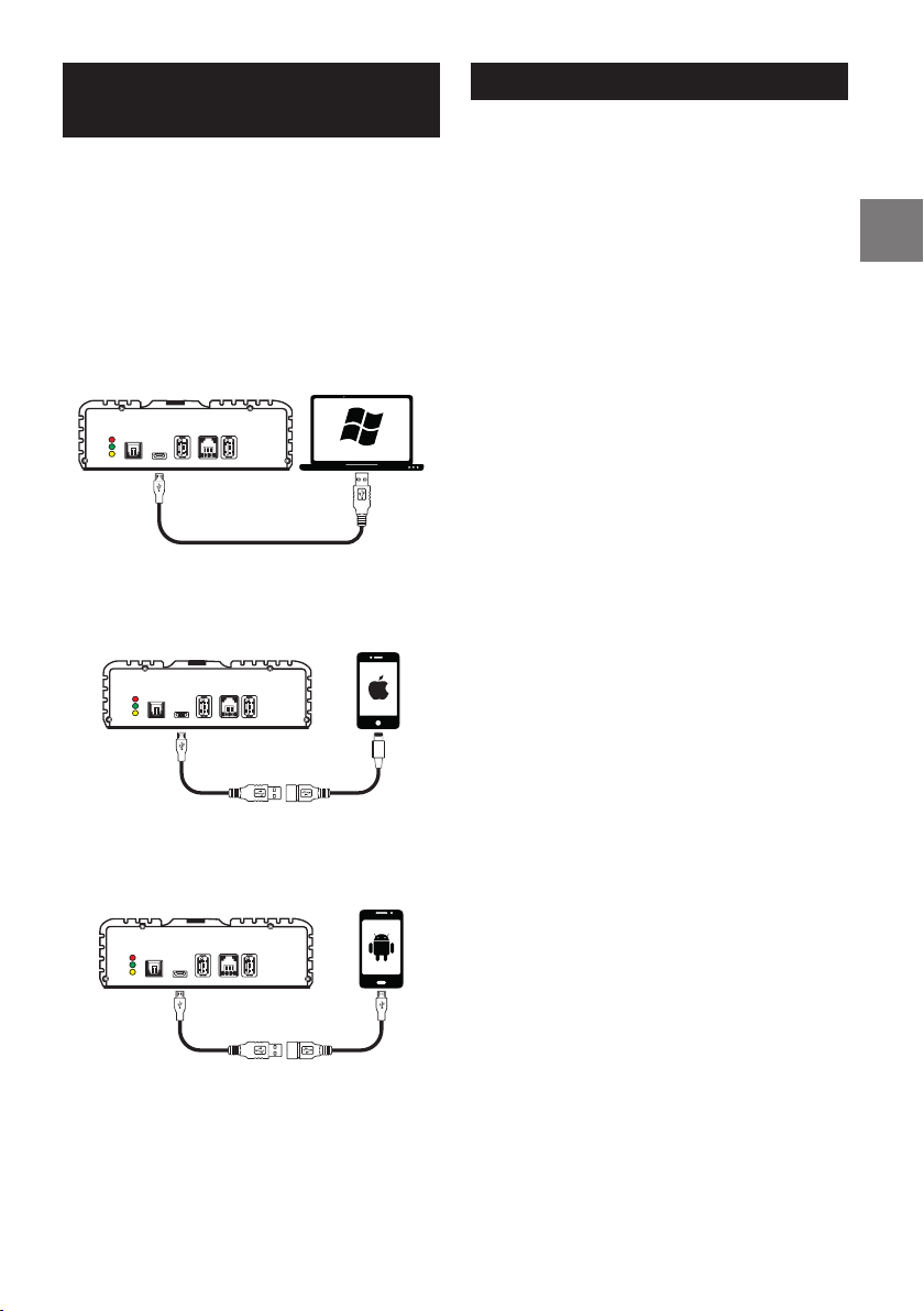
PC Connection
Connect a Windows PC to the PDP‑E802DSP’s
Micro USB port labeled ‘PC’.
USB RC WIFI
OPT IN
PROT
STAT
PC
LINK
iPhone Connection
Connect an Apple device via Apple´s camera
connection kit to the PDP‑E802DSP’s Micro USB
port labeled ‘PC’.
USB RC WIFI
OPT IN
PROT
STAT
PC
LINK
Android Connection
Connect an Android device via OTG kit to the
PDP‑E802DSP’s Micro USB port labeled ‘PC’. Host
mode must be supported by the phone.
USB RC WIFI
OPT IN
PROT
STAT
PC
LINK
WIRELESS STREAMING
• Audio streaming from iOS using Airplay. *
• Audio streaming from Android devices using
casting apps that support UPnP/DLNA. *
* Hi‑Resolution audio streaming apps required for
24‑bit/92kHz audio files.
Wireless streaming with iOS
1. Connect your iOS device with the PDP‑E802DSP
amplifier as described in “ALPINE REMOTE
CONTROL APP FOR PDP‑E802DSP” on page
26.
2. Select Streaming as source within the remote
app or PC software
3. Start Apple Airplay and select „PDP‑E802DSP “ as
destination
4. Start playback
Wireless streaming with Android Devices
1. Start a wireless connection from your Android
device to the PDP‑E802DSP amp as described in
“ALPINE REMOTE CONTROL APP FOR
PDP‑E802DSP” on page 26.
2. Select Streaming as source within the remote
app or PC software
3. Start your DLNA streaming app on your device
and select „PDP‑E802DSP“ as destination.
4. Start playback within the streaming app.
Procedure and settings may differ depending on
device and Android version.
In all cases above, the source of the
PDP‑E802DSP needs to be set to USB using the
ALPINE Sound Lab or the ALPINE Remote app.
27-EN
Page 28

SYSTEM EXAMPLES
3-way Front System + 2 Subwoofer
28-EN
Page 29
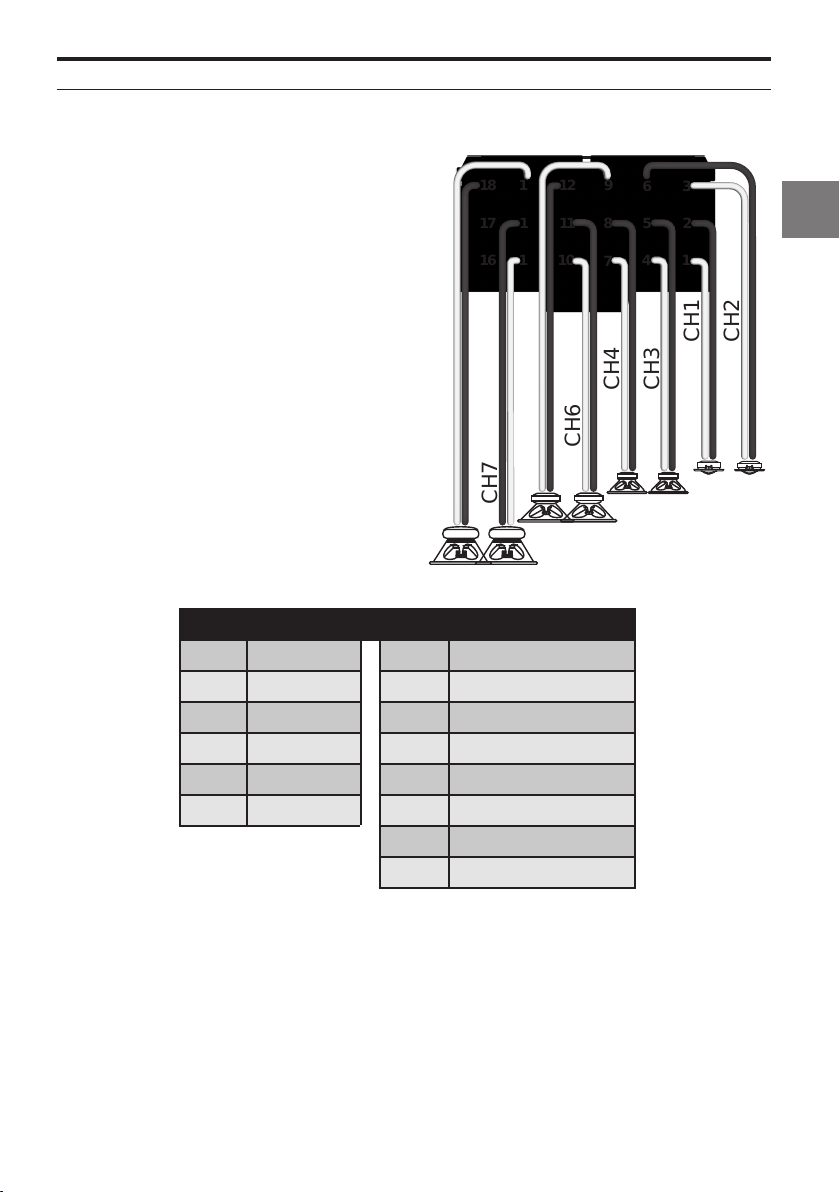
3-way Front System + 2 Subwoofer
SPEAKER OUTPUT
Possible routing for this setup
Input/ Output Assignments:
Input Assignment Output Assignment
CH 1 Front Left CH 1 Tweeter Front Left
CH 2 Front Right CH 2 Tweeter Front Right
CH 3 Rear Left CH 3 Midrange Front Left
CH 4 Rear Right CH 4 Midrange Front Right
CH 5 Subwoofer 1 CH 5 Low Range Front Left
CH 6 Subwoofer 2 CH 6 Low Range Front Right
CH 7 Subwoofer Left
CH 8 Subwoofer Right
Output Connections
15
18
14
17
13
16
CH5
CH7
CH8
12
11
10
9
8
7
CH6
6
5
4
CH4
3
2
1
CH3
CH1
CH2
29-EN
Page 30

3-way Front System + Center + Subwoofer
30-EN
Page 31
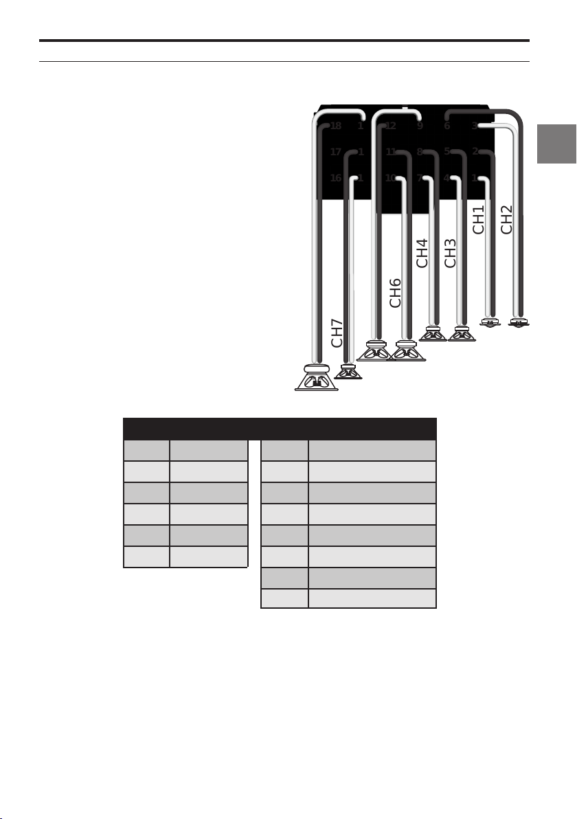
3-way Front System + Center + Subwoofer
SPEAKER OUTPUT
Possible routing for this setup
Input/ Output Assignments:
Input Assignment Output Assignment
CH 1 Front Left CH 1 Tweeter Front Left
CH 2 Front Right CH 2 Tweeter Front Right
CH 3 Rear Left CH 3 Midrange Front Left
CH 4 Rear Right CH 4 Midrange Front Right
CH 5 Subwoofer 1 CH 5 Low Range Front Left
CH 6 Subwoofer 2 CH 6 Low Range Front Right
Output Connections
CH8
CH 7 Center
CH 8 Subwoofer
18
17
16
15
14
13
CH7
12
11
10
CH5
9
8
7
CH6
6
5
4
CH4
3
2
1
CH3
CH1
CH2
31-EN
Page 32

3-way Front System + Center + Mono Amplifier + Subwoofer
Note:
We do recommend connecting high quality
amplifiers with differential RCA input/s
(ground isolated) in order to avoid unwanted
noise.
32-EN
Page 33
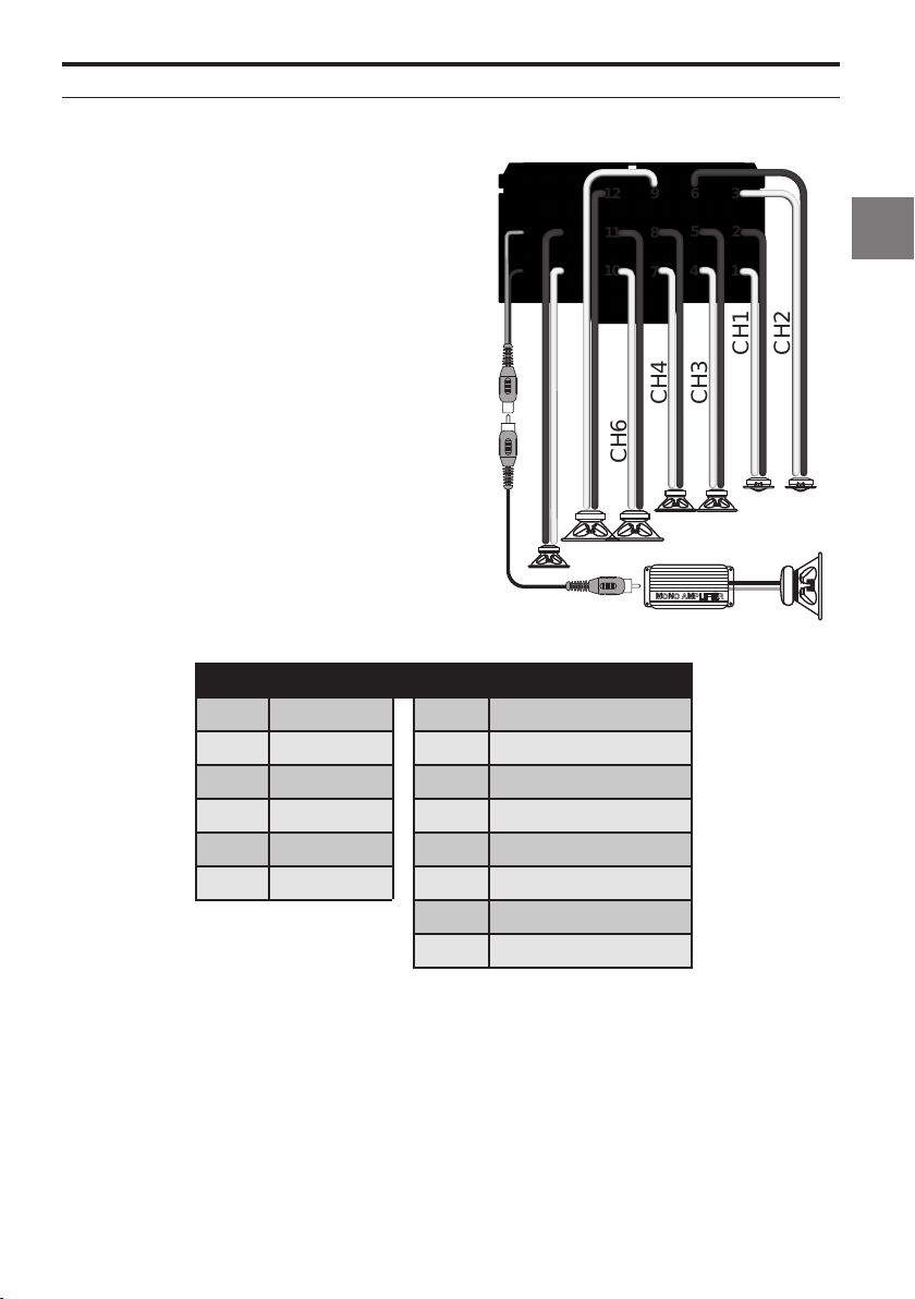
3-way Front System + Center + Mono Amplifier + Subwoofer
SPEAKER OUTPUT
Possible routing for this setup
Input/ Output Assignments:
Input Assignment Output Assignment
CH 1 Front Left CH 1 Tweeter Front Left
CH 2 Front Right CH 2 Tweeter Front Right
CH 3 Rear Left CH 3 Midrange Front Left
CH 4 Rear Right CH 4 Midrange Front Right
CH 5 Subwoofer 1 CH 5 Low Range Rear Left
CH 6 Subwoofer 2 CH 6 Low Range Rear Right
Output Connections
12
15
18
14
17
16
13
11
10
CH5
CH6
CH7
Pre Out
CH 7 Center
RCA To External Amplifier
9
6
5
8
4
7
CH4
MONO AMPLIFIER
CH3
3
2
1
CH1
CH2
33-EN
Page 34

2-way Front System + 2-way Passive Rear System + 2 Subwoofer
34-EN
Page 35
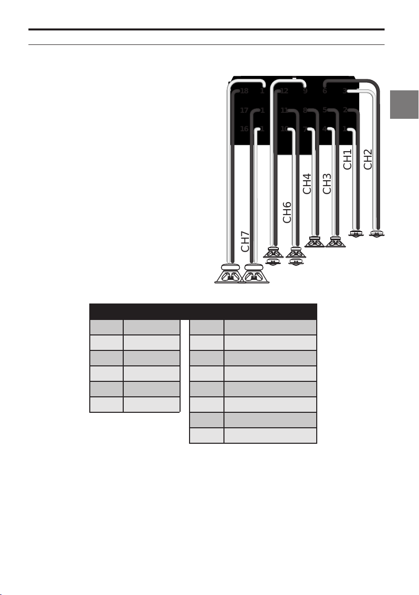
2-way Front System + 2-way Passive Rear System + 2 Subwoofer
SPEAKER OUTPUT
Possible routing for this setup
Input/ Output Assignments:
Input Assignment Output Assignment
CH 1 Front Left CH 1 Tweeter Front Left
CH 2 Front Right CH 2 Tweeter Front Right
CH 3 Rear Left CH 3 Low Range Front Left
CH 4 Rear Right CH 4 Low Range Front Right
CH 5 Subwoofer 1 CH 5 Full Range Rear Left
CH 6 Subwoofer 2 CH 6 Full Range Rear Right
Output Connections
15
18
14
17
13
16
CH5
CH7
CH8
CH 7 Subwoofer Left
CH 8 Subwoofer Right
12
11
10
9
8
7
CH6
6
5
4
CH4
3
2
1
CH1
CH3
CH2
35-EN
Page 36

TROUBLESHOOTING
No power at DSP
• Check DSP amp main fuse under the bottom
cover.
Check vehicle battery voltage.
•
• Check DSP harness for a secure and low
resistance ground point.
• Check Autoremote status in the app. The status
should be set to “off” if using remote input
wire. If this feature is on, the DSP IS waiting for
an audio signal trigger from Hi‑level or RCA
inputs.
• Keep in mind autodetection is only available
on dedicated input channels:
DC Detection: Channels 1, 2
AC Detection: Channels 5, 6
• If the amplifier is used in AC detect mode and
switches off during the tunig process, the
amplifier will start in update mode. In this case,
the USB connection and the power connector
need to be disconnected.
Low Volume while streaming from smart device
• Check device volume or streaming app
volume.
• Check RC volume level.
No wireless network available
• Wireless signal could be blocked or shielded
due to installation. Move wireless module to
another location.
• Restart Wireless module by cycling power to
the DSP.
• Cycle amplifier power to restart it.
• Reconnect PDP‑E802DSP app.
Data connection to DSP not stable
• Data connection to DSP amp is active only
when ALPINE Sound Lab is active. Data
connection is terminated on Android devices
as soon as App is working in background.
• Check if other apps in background may access
the Wi‑Fi data connection and terminate these
Apps.
No data connection to DSP, while wireless
network connection is established successfully
• Use another USB cable.
• Restart wireless module by cycling power to
the DSP.
• Try hard wired connection with Windows PC by
using a high quality Micro‑USB cable.
You only have limited access to a setting
(6 Band EQ)
• You don´t have the rights to access this setting.
• Check your certificates.
Wireless connection is not stable
• Wireless module cables must be extended as
much as possible. DO NOT bundle excess cable
near the amplifier.
• Check if nearby Wi‑Fi networks are transmitting
on the same or neighbor channels. If so,
configure the wireless module to another
channel. Keep 5 channels distance to any other
strong wireless network. 11 channels are
available.
• Always check to see if your app firmware is up
to date.
DSP app message “IN CONNECTION”
• Wireless module is connected to another
device already. Disconnect all device
connections and reconnect with one device
only.
• Close PDP‑E802DSP app.
36-EN
Page 37

FIRMWARE UPDATE
Firmware update procedure
1. Download the latest Firmware file from your
local Alpine homepage.
2. Check the support area. For latest software.
3. Extract the firmware file.
4. Disconnect the power connector.
5. Connect the DSP‑E802DSP to your computer
(with supplied micro USB cable).
6. The amp will be recognized as disk drive.
7. Delete the old file. The firmware file has always
the same name ‘software.apn’. No version
number is shown.
8. Drag and drop the new Firmware file to the
ALPINE AMP folder.
9. Reconnect power.
10. With the next amp start the new firmware will
be loaded. It will automatically be renamed to
„software.apn“.
37-EN
Page 38
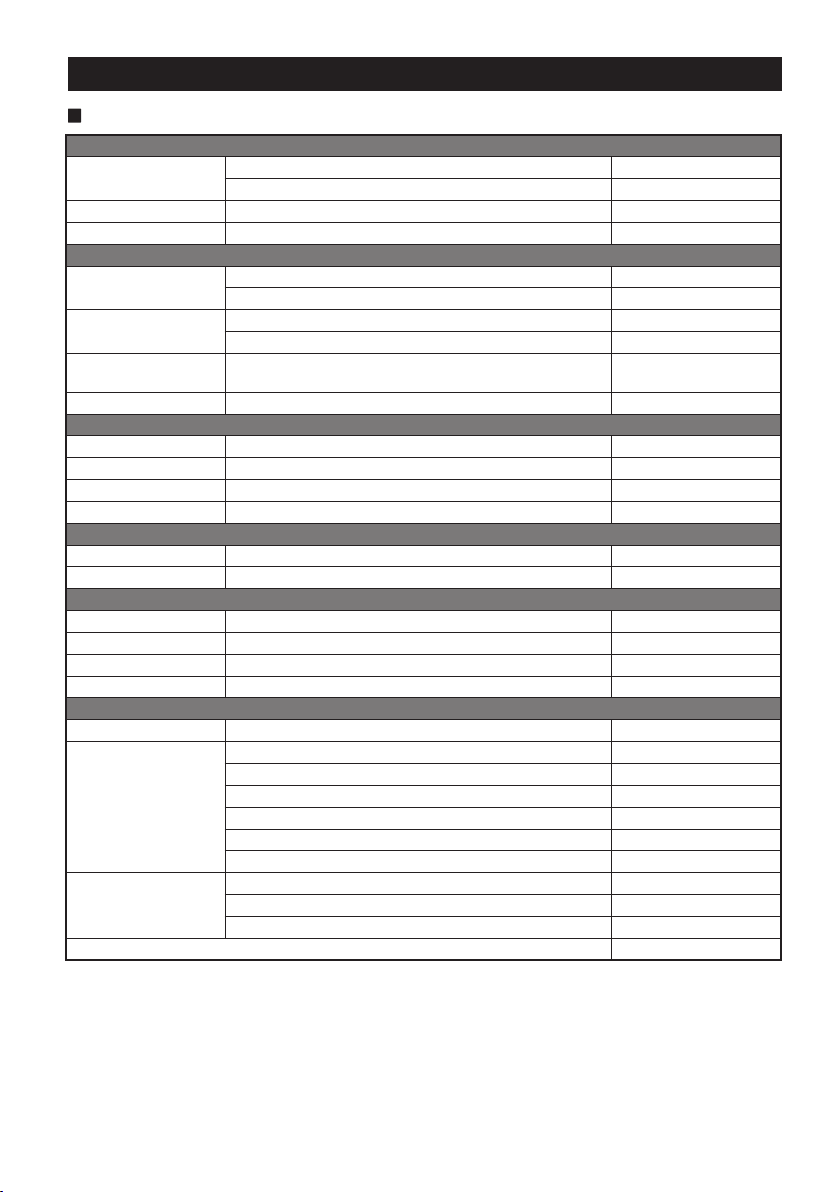
SPECIFICATIONS
PDP-E802DSP
Performance
Power Output
Frequency Response
Damping Factor >100
Inputs
Analogue
Input Sensitivity
Digital Optical (S/PDIF LPCM)
Remote In 12VDC
Outputs
Speaker ≥2Ω 8x
Pre‑Out Channel 8 signal, 2V RMS 1x
Remote Out 12VDC, 100mA nom. 1x
Preset Toggle
Digital Signal Processor
Resolution 64bit @ 96kHz
Working Frequency 294.912MHz
Analogue Digital Converter
S/N Ratio Burr Brown >105dB
Channel Separation >75dB
THD 0.003%
Resolution 24bit @ 96kHz
General
Operation Voltage Start/stop compliant
Additional Features
Dimensions
Weight 1.6kg
NOTE:
• Specifications and design are subject to change without notice
Per Channel, Ref.: 4Ω, 14.4 V, <1% THD 100W RMS
Per Channel, Ref.: 2Ω, 14.4 V, <1% THD+N 120W RMS
20 Hz ‑ 22 kHz
RCA (Low Level) 6x
Speaker Line (High Level) 6x
RCA (Low Level) (10kΩ): 0.5 to 4V (rms)
Speaker Line (High Level) (22Ω): 2 to 18V (rms)
12kHz ‑ 96kHz
16bit/ 24bit
2.5VDC ‑ 14,4VDC 1x
11VDC ‑ 16VDC nom.
Remote Auto Sensing
2x USB Client
1x USB Host
Remote Port for RUX‑KNOB
Parallel mode ready
All wires detachable
Width 220mm
Height 50mm
Depth 150mm
38-EN
Page 39

39-EN
Page 40

Page 41

OM PDP-E802DSP - A
 Loading...