

Page 1
Burkard Bovensiepen GmbH+Co.
Alpenstraße 35-37,D-86807 Buchloe
Service Manual
Dwg.-Nr. Page 1 of 25
88 03 175
Prepared by Date
Engineering 20 July 2000
BMW/ALPINA D10 BITURBO
Service Manual
BMW / ALPINA D10 Biturbo
The servicing covered herein should be undertaken by qualified mechanics only.
This manual has been based on the service manual for the BMW 530d.
All torque specifications are listed in the service manual for the BMW 530d.
Page 2

Burkard Bovensiepen GmbH+Co.
Alpenstraße 35-37,D-86807 Buchloe
Service Manual
Dwg.-Nr. Page 2 of 25
88 03 175
Prepared by Date
Engineering 20 July 2000
BMW/ALPINA D10 BITURBO
Contents:
Page
11 61 Checking the swirl flaps for proper operation 3
11 62 Removing and reinstalling, sealing, or replacing the exhaust manifolds 4
11 65 Removing and reinstalling/replacing the exhaust-gas turbochargers 5
11 71 Removing and reinstalling/replacing the EGR-system 10
13 51 Removing and reinstalling/replacing the high-pressure fuel pump 14
13 53 Removing and reinstalling/replacing the fuel distributor 19
18 00 Removing and reinstalling/replacing the exhaust system as a unit 22
18 31 Removing and reinstalling/replacing the precatalyst 24
Page 3
Burkard Bovensiepen GmbH+Co.
Alpenstraße 35-37,D-86807 Buchloe
Service Manual
Dwg.-Nr. Page 3 of 25
88 03 175
Prepared by Date
Engineering 20 July 2000
BMW/ALPINA D10 BITURBO
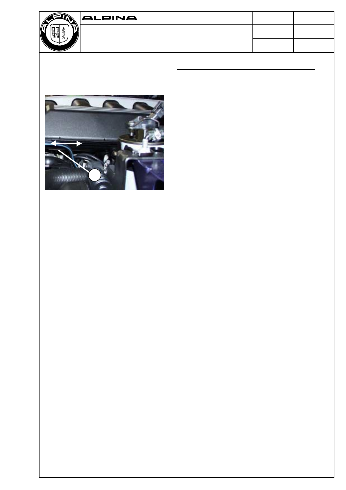
11 61 Checking the swirl flaps for proper operation
The swirl flaps are actuated by the linkage (1)
whenever the vehicle’s engine is started, shut off, or
reaches approximately 2.200 rpm.
1
Page 4
Burkard Bovensiepen GmbH+Co.
Alpenstraße 35-37,D-86807 Buchloe
Service Manual
BMW/ALPINA D10 BITURBO
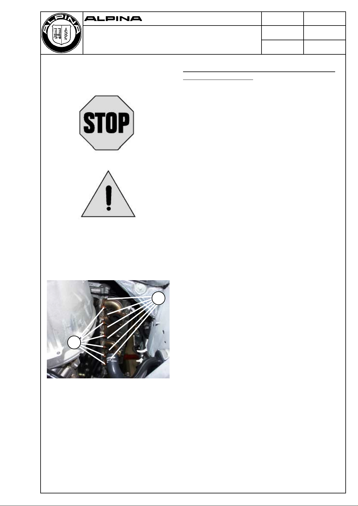
11 62 Removing and reinstalling, sealing, or replacing
the exhaust manifolds
Warning!
Burn hazards!
Do not attempt any of the following servicing operations
until the vehicle’s engine has cooled down.
Caution!
Installing charge-air hoses that are not perfectly dry and
free of grease can cause a failure of the charge-air
system.
Make certain that the charge-air hoses are perfectly dry
and free of grease before reinstalling them.
Dwg.-Nr. Page 4 of 25
88 03 175
Prepared by Date
Engineering 20 July 2000
Refer to p. 5 of this manual for instructions on removing
and reinstalling the exhaust-gas turbochargers.
Remove the nuts (1) holding the exhaust manifolds in
place and remove both exhaust manifolds.
1
Reinstalling the exhaust manifolds:
- Use all new gaskets and seals.
- Coat the threads on the manifold studs with a thin
layer of copper paste (CRC), which is available from
1
BMW’s parts department.
- Replace the nuts (1) with new nuts.
- Torque the nuts down, working from the centers of the
exhaust manifolds toward their outer ends.
Page 5
Burkard Bovensiepen GmbH+Co.
Alpenstraße 35-37,D-86807 Buchloe
Service Manual
BMW/ALPINA D10 BITURBO
11 65 Removing and reinstalling / replacing the exhaust-
gas turbochargers
Warning!
Burn hazards!
Do not attempt any of the following servicing operations
until the vehicle’s engine has cooled down.
Caution!
Installing charge-air hoses that are not perfectly dry and
free of grease can cause a failure of the charge-air
system.
Make certain that the charge-air hoses are perfectly dry
and free of grease before reinstalling them.
Dwg.-Nr. Page 5 of 25
88 03 175
Prepared by Date
Engineering 20 July 2000
Refer to p. 24 of this manual for instructions on
removing and reinstalling the precatalysts.
Drain approximately 3 liters of motor oil from the
crankcase.
Remove the fan cowl.
Refer to Dwg. No. 17 11 031 for instructions on
removing and reinstalling the fan cowl.
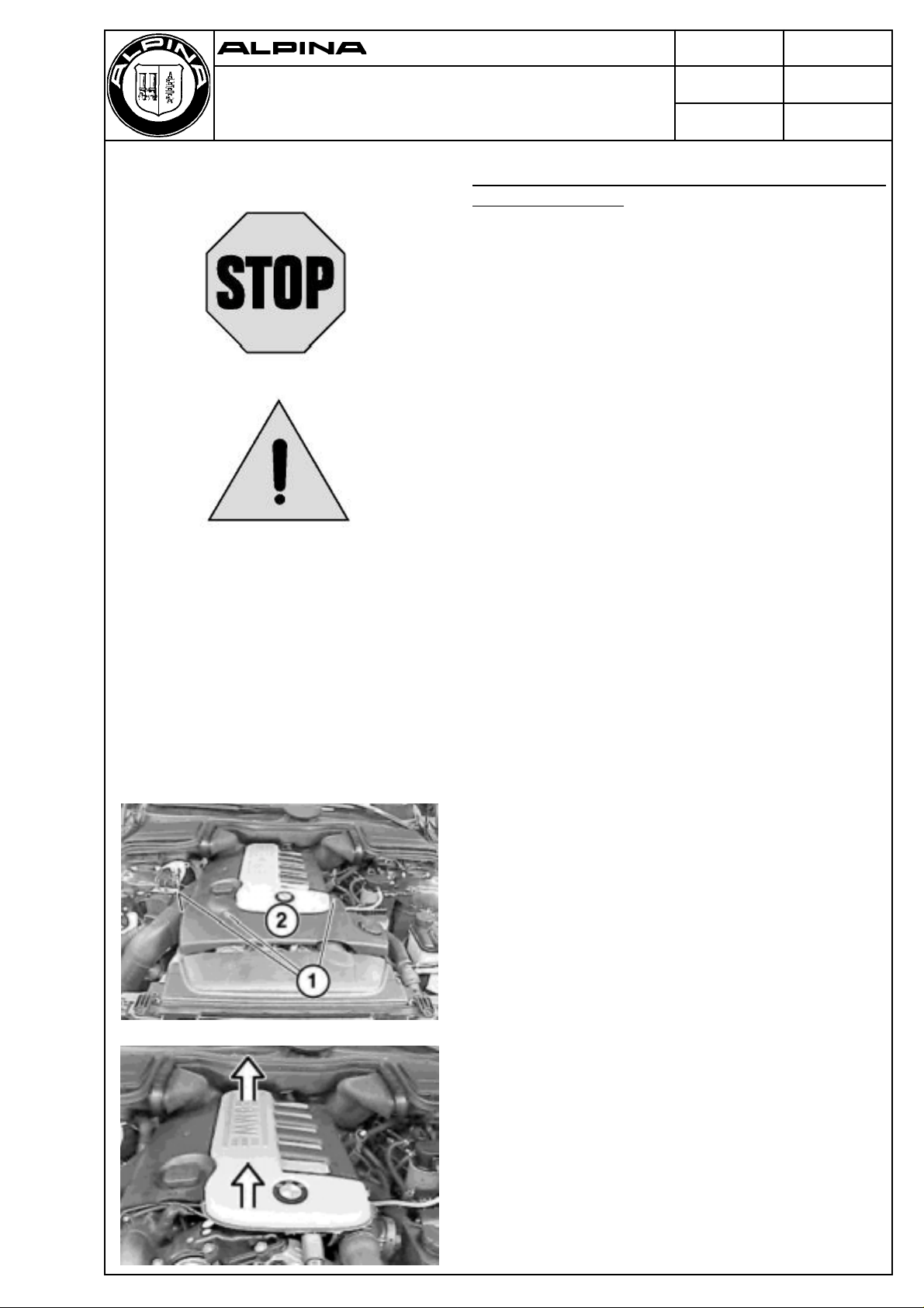
Remove the screws (1) holding the silencer shroud (2)
in place and slide the silencer shroud forward.
Lift off the silencer shroud.
Page 6
Burkard Bovensiepen GmbH+Co.
Alpenstraße 35-37,D-86807 Buchloe
Service Manual
BMW/ALPINA D10 BITURBO
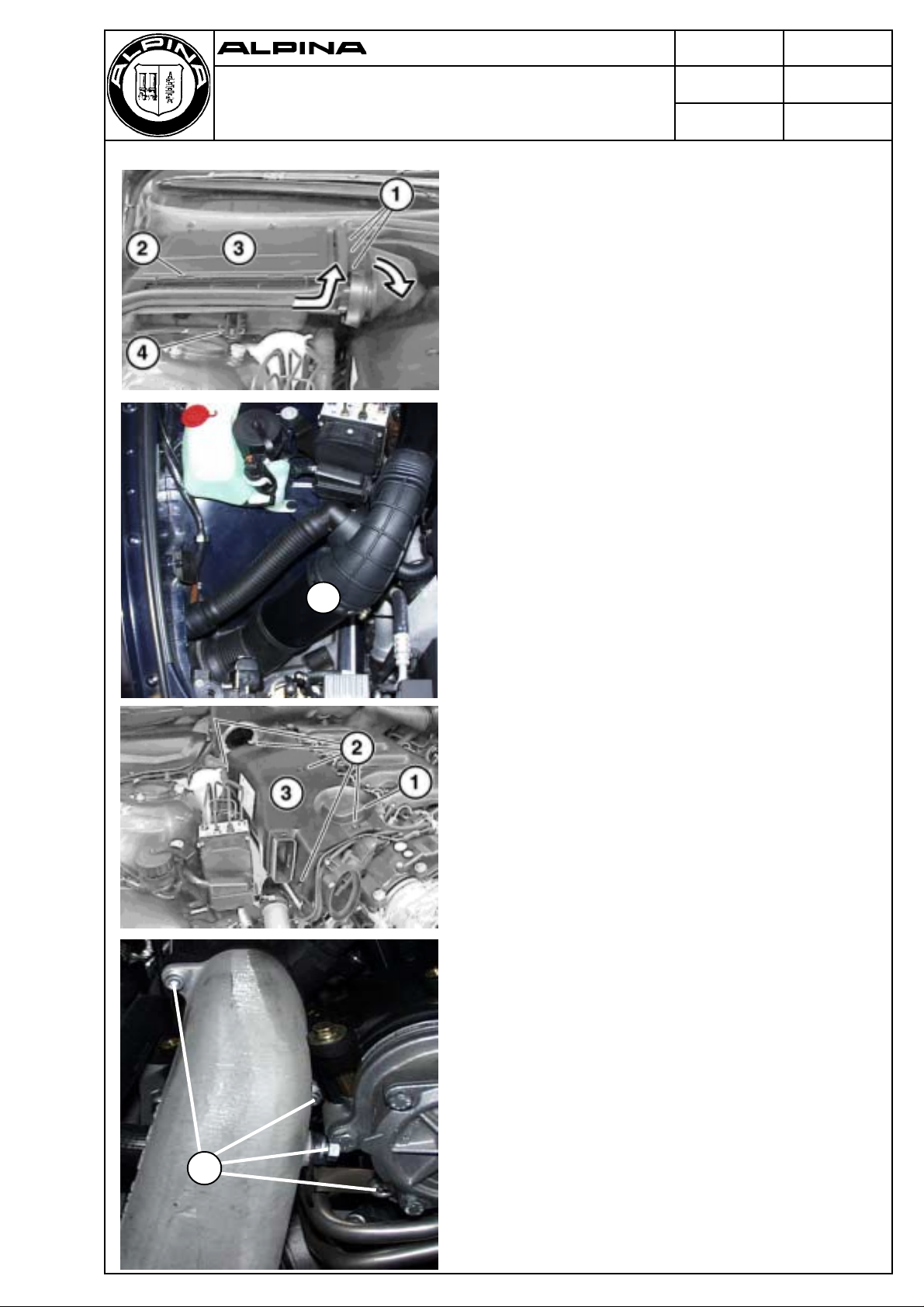
Release the clips (1) and withdraw the air duct, as
shown by the arrow.
Release the clamping bail (2).
Remove the cover (3) from the microfilter housing.
Open the clamp (4).
Rotate the microfilter housing in the direction of the
arrow and withdraw it upward.
Remove the intake duct assembly (1).
Dwg.-Nr. Page 6 of 25
88 03 175
Prepared by Date
Engineering 20 July 2000
1
Remove the cap (1).
Remove the screws (2) holding the air-filter cover (3) in
place.
Lift off the air-filter cover (3).
Remove the airduct mounting bolts (1).
1
Page 7
Burkard Bovensiepen GmbH+Co.
Alpenstraße 35-37,D-86807 Buchloe
Service Manual
Dwg.-Nr. Page 7 of 25
88 03 175
Prepared by Date
Engineering 20 July 2000
BMW/ALPINA D10 BITURBO
Loosen the clamps (1) on the molded hoses.
Remove the crankcase-ventilation hose (2).
Remove the distributor on the air-intake duct complete
1
3
2
with the intake duct for Turbocharger 1 by pulling it
forward.
Remove the intake duct (3) for Turbocharger 2.
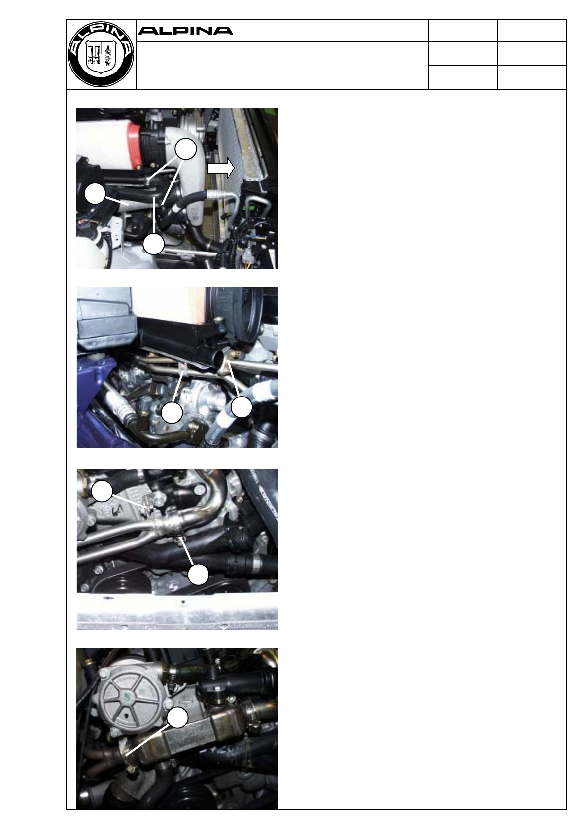
Remove the clamp (1).
Remove the fittings fastening the EGR-lines to the rear
exhaust manifold and the nuts on the flange (2).
Remove the rear EGR-line.
Remove the fitting fastening the EGR-line to the front
exhaust manifold.
1
2
Vehicles equipped with manual transmissions only:
1
Remove the bolt and nut (1) holding the fitting in place.
Loosen the clamp (2) and remove the front EGR-line.
2
Vehicles equipped with automatic transmissions
only:
Loosen the clamp (1) and remove the front EGR-line.
1
Page 8
Burkard Bovensiepen GmbH+Co.
Alpenstraße 35-37,D-86807 Buchloe
Service Manual
BMW/ALPINA D10 BITURBO
Unscrew the hollow bolt (1).
Remove the oil lines (2).
Dwg.-Nr. Page 8 of 25
88 03 175
Prepared by Date
Engineering 20 July 2000
2
Note:
Seal the fittings for the oil lines and the openings in the
1
crankcase housing using suitable caps or plugs.
Note on reinstallation:
New seals are to be used when reinstalling
components.
Loosen the clamp (1) on the hose (2) on the front
1
2
turbocharger’s exit port and remove the hose (2).
1 4
Loosen the clamp (1) on the oil-return hose and remove
the oil-return hose.
Unscrew the oil-return tube (2) on the turbocharger.
Loosen the clamp (3) on the hose (4) on the rear
turbocharger’s exit port and remove the hose (4).
3
2
Remove the tube on the intercooler intake port and
move it aside.
Page 9

Burkard Bovensiepen GmbH+Co.
Alpenstraße 35-37,D-86807 Buchloe
Service Manual
Dwg.-Nr. Page 9 of 25
88 03 175
Prepared by Date
Engineering 20 July 2000
BMW/ALPINA D10 BITURBO
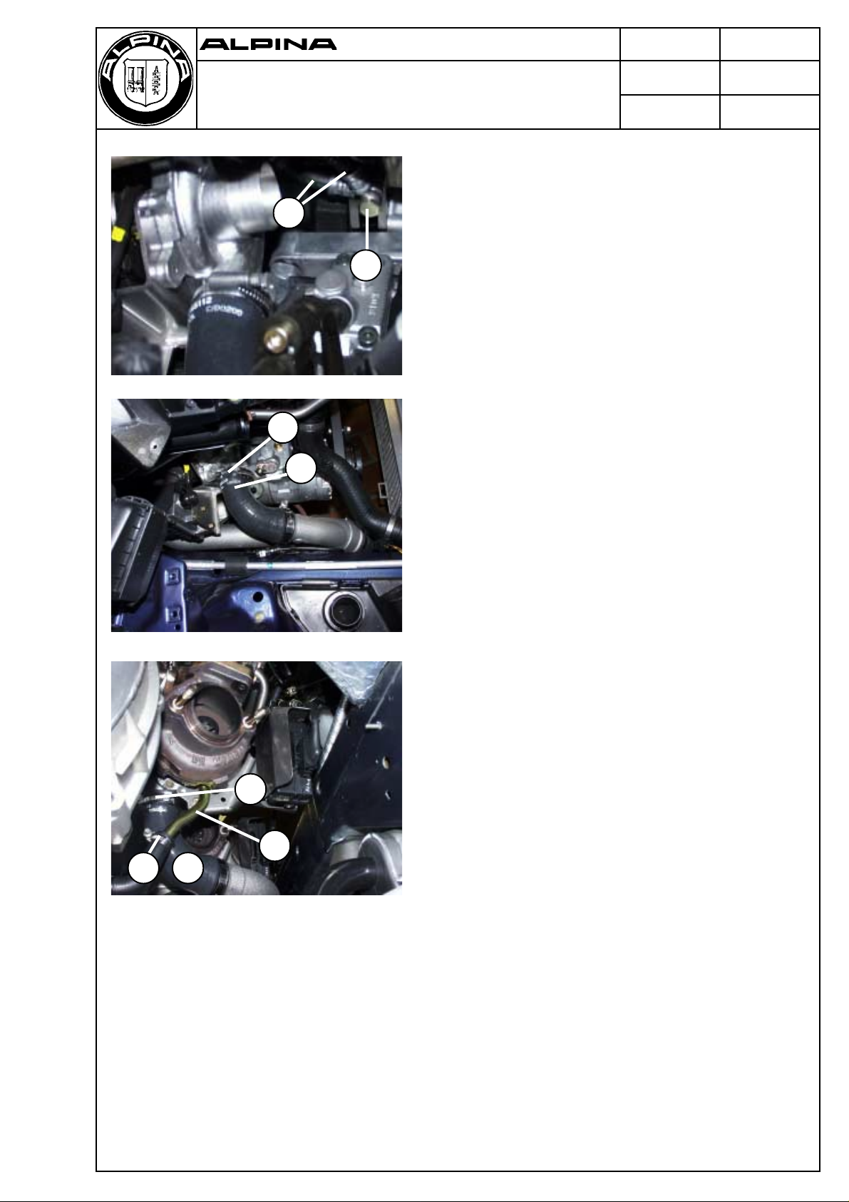
Loosen the clamps (1).
Remove both hoses (2).
2
1
Unplug the connector (1).
Unscrew the three bolts (2) holding each turbocharger
in place and withdraw both turbochargers from below.
2
1
Installing / reinstalling turbochargers:
- When fitting new turbochargers, the condition of the
oil suppley and return lines should be taken into
consideration.
- Replace all gaskets and seals with new ones.
- Clean mating surfaces on the exhaust manifolds
before reinstalling them.
- Replace the seals on the turbochargers.
- Refill the crankcase with motor oil.
Test drive the vehicle.
Check the oil level in the engine crankcase.
Check all lines and joints for leaks.
Page 10

Burkard Bovensiepen GmbH+Co.
Alpenstraße 35-37,D-86807 Buchloe
Service Manual
BMW/ALPINA D10 BITURBO
11 71 Removing and reinstalling / replacing the exhaust-
gas-recirculation (EGR) lines
Warning!
Burn hazards!
Do not attempt any of the following servicing operations
until the vehicle’s engine has cooled down.
Remove the screws (1) holding the silencer shroud (2)
in place and slide the silencer shroud forward.
Dwg.-Nr. Page 10 of 25
88 03 175
Prepared by Date
Engineering 20 July 2000
Refer to Dwg. No. 17 11 031 for instructions on
removing and reinstalling the fan cowl.
Lift off the silencer shroud.
Release the clips (1) and withdraw the air duct, as
shown by the arrow.
Release the clamping bail (2).
Remove the cover (3) from the microfilter housing.
Open the clamp (4).
Rotate the microfilter housing in the direction of the
arrow and withdraw it upward.
Page 11

Burkard Bovensiepen GmbH+Co.
Alpenstraße 35-37,D-86807 Buchloe
Service Manual
BMW/ALPINA D10 BITURBO
Remove the intake duct assembly (1).
1
Dwg.-Nr. Page 11 of 25
88 03 175
Prepared by Date
Engineering 20 July 2000
Remove the cap (1).
Remove the screws (2) holding the air-filter cover (3) in
place.
Lift off the air-filter cover (3).
Remove the airduct mounting bolts (1).
1
Page 12

Burkard Bovensiepen GmbH+Co.
Alpenstraße 35-37,D-86807 Buchloe
Service Manual
Dwg.-Nr. Page 12 of 25
88 03 175
Prepared by Date
Engineering 20 July 2000
BMW/ALPINA D10 BITURBO
Loosen the clamps (1) on the molded hoses.
Remove the crankcase-ventilation hose (2).
Remove the distributor on the air-intake duct complete
1
3
2
with the intake duct for turbocharger 1 by pulling it
forward.
Remove the intake duct (3) for turbocharger 2.
Remove the clamp (1).
Unscrew the fitting for the EGR-line on the rear exhaust
manifold and the bolts on the flanged joint (2).
Remove the rear EGR-line.
Unscrew the fitting for the EGR-line on the front exhaust
manifold.
1
2
Vehicles equipped with manual transmissions only:
1
Remove the bolt and nut (1) holding the fitting in place.
Loosen the clamp (2) and remove the front EGR-line
(3).
3
2
Vehicles equipped with automatic transmissions
only:
Drain the cooling system.
1
Refer to Dwg. No. 17 00 005 for instructions on draining
the cooling system.
Remove all water lines from the EGR-cooler.
2
Loosen the hose clamps (1) and remove the front
EGR-line (2).
Remove the pair of bolts holding the EGR-cooler in
place and remove the EGR-cooler.
Page 13

Burkard Bovensiepen GmbH+Co.
Alpenstraße 35-37,D-86807 Buchloe
Service Manual
Dwg.-Nr. Page 13 of 25
88 03 175
Prepared by Date
Engineering 20 July 2000
BMW/ALPINA D10 BITURBO
Loosen the clamp (1).
1
2
Remove the EGR-line (2).
Reinstalling the EGR-lines:
- Refill the cooling system.
- Check the cooling system for leaks.
Page 14

Burkard Bovensiepen GmbH+Co.
Alpenstraße 35-37,D-86807 Buchloe
Service Manual
BMW/ALPINA D10 BITURBO
13 51 Removing and reinstalling / replacing the high-
pressure fuel pump
Switch off the ignition.
Warning!
Cover the alternator with plastic foil or other suitable
material before undertaking any work on vehicle’s oil,
cooling, or fuel systems in order to prevent liquids or
other contamination entering the alternator.
Failure to do so may lead to an alternator failure.
After removing the fuel-injector lines, seal all openings
on the high-pressure fuel pump, fuel distributor and
common rail with suitable caps or plugs.
The timing of the pump’s operation is arbitrary, since its
operation is not synchronized to that of the engine’s
valve gear.
Dwg.-Nr. Page 14 of 25
88 03 175
Prepared by Date
Engineering 20 July 2000
Safe disposal of Diesel fuel:
Catch any Diesel fuel that escapes and dispose of it in
accordance with federal, state, and local regulations
governing safe disposal of motor fuels.
Page 15

Burkard Bovensiepen GmbH+Co.
Alpenstraße 35-37,D-86807 Buchloe
Service Manual
BMW/ALPINA D10 BITURBO
Remove the fan cowl.
Refer to Dwg. No. 17 11 031 for instructions on
removing and reinstalling the fan cowl.
Remove the intake manifold.
Refer to Dwg. No. 11 61 050 for instructions on
removing the intake manifold.
Caution!
Do not forget to unplug the connector and remove both
vacuum hoses on the transfer valve (1) before
removing the intake manifold.
Dwg.-Nr. Page 15 of 25
88 03 175
Prepared by Date
Engineering 20 July 2000
1
Drain the cooling system.
Refer to Dwg. No. 17 00 005 for instructions on
draining the cooling system.
Remove both bolts (1).
Loosen the clamps on each end of the coolant
recirculation tube (2) and remove the recirculation tube
(2).
2
Remove the coolant tube (3) on the crankcase
housing.
Refer to Dwg. No. 17 00 ... for further instructions on
working on the cooling system.
1
3
Remove the oil-filter assembly.
Refer to Dwg. No. 11 42 020 for instructions on
removing the oil-filter assembly.
Note:
The fastening bolt on the forward end of the oil-filter
housing is a 6-mm Allen-head bolt.
A special wrench (ALPINA 74 00 126) is needed for
removing this bolt.
Page 16

Burkard Bovensiepen GmbH+Co.
Alpenstraße 35-37,D-86807 Buchloe
Service Manual
Dwg.-Nr. Page 16 of 25
88 03 175
Prepared by Date
Engineering 20 July 2000
BMW/ALPINA D10 BITURBO
Unplug the connectors (1) on the pump and pressure
regulator.
1
2
Remove the fuel lines (2) from the pump.
Note on reinstalling the fuel lines:
Loosen the clamps (1) on the fuel lines (2).
1
2
1
1
Use new clamps when reinstalling the fuel lines.
Unplug the connector (1) on the glow plug.
Unscrew the union nuts (2) on the fuel lines
pump - fuel distributor and fuel distributor - rail usingthe
2
special wrench (13 5 020) available for this purpose.
Remove the fuel line pump - fuel distributor.
Move the fuel line fuel distributor - rail aside.
Remove the bolts (3) holding the fuel distributor in place
and remove the fuel distributor.
3
Page 17

Burkard Bovensiepen GmbH+Co.
Alpenstraße 35-37,D-86807 Buchloe
Service Manual
BMW/ALPINA D10 BITURBO
Unscrew the nuts (1) on the high-pressure pump.
Take the ribbed V-belt driving the alternator off its
tensioning pulley.
Unscrew the screw plug (1).
Dwg.-Nr. Page 17 of 25
88 03 175
Prepared by Date
Engineering 20 July 2000
Note on replacing the screw plug:
Put a new seal on the plug before replacing it.
Unscrew the nut (1) holding the pump’s chain wheel on
the pump’s shaft.
Insert the special tool (13 5 190) into the opening on the
gearbox cover while rotating it clockwise.
Page 18

Burkard Bovensiepen GmbH+Co.
Alpenstraße 35-37,D-86807 Buchloe
Service Manual
BMW/ALPINA D10 BITURBO
Screw the special tool (13 5 190) into the recess in the
high-pressure pump’s chain wheel and then screw the
other special tool (13 5 191) into the tapped hole in
special tool 13 5 190 until its hex nut abuts against
the outer face of special tool 13 5 190.
Tighten the bolt (1) until the chain wheel has been
driven completely out of its housing.
Remove the high-pressure pump.
Dwg.-Nr. Page 18 of 25
88 03 175
Prepared by Date
Engineering 20 July 2000
Caution!
The special tool (13 5 190) must be left in position in
order to hold the high-pressure pump’s chain wheel in
place. Under no circumstances should it be removed
before all other work has been completed.
Unscrew the bolt (1) before reinstalling the highpressure pump.
Notes on reinstalling the high-pressure pump:
- Use a new gasket (1).
- Make certain that the gasket (1) is correctly oriented.
- All mating surfaces should be perfectly dry and free
of grease prior to reassembly.
Bleeding the fuel system:
To bleed the fuel system, proceed as follows:
Pinch off the fuel-return line (1).
Switch on the ignition and leave it on for about 1 minute.
Start the engine.
The fuel system will now be filled with fuel and all air will
have been expelled.
1
Open the fuel-return line (1).
Switch off the engine.
Page 19

Burkard Bovensiepen GmbH+Co.
Alpenstraße 35-37,D-86807 Buchloe
Service Manual
BMW/ALPINA D10 BITURBO
13 53 Removing and reinstalling / replacing the fuel
distributor
Switch off the ignition.
Warning!
Cover the alternator with plastic foil or other suitable
material before undertaking any work on vehicle’s oil,
cooling, or fuel systems in order to prevent liquids or
other contamination entering the alternator.
Failure to do so may lead to an alternator failure.
Dwg.-Nr. Page 19 of 25
88 03 175
Prepared by Date
Engineering 20 July 2000
After removing the fuel-injector lines, seal all openings
on the high-pressure fuel pump, fuel distributor and
common rail with suitable caps or plugs.
The timing of the pump’s operation is arbitrary, since its
operation is not synchronized to that of the engine’s
valve gear.
Safe disposal of Diesel fuel:
Catch any Diesel fuel that escapes and dispose of it in
accordance with federal, state, and local regulations
governing safe disposal of motor fuels.
Page 20

Burkard Bovensiepen GmbH+Co.
Alpenstraße 35-37,D-86807 Buchloe
Service Manual
BMW/ALPINA D10 BITURBO
Remove the intake manifold.
Refer to Dwg. No. 11 61 050 for instructions on
removing the intake manifold.
Caution!
Do not forget to unplug the connector and remove both
vacuum hoses on the transfer valve (1) before
removing the intake manifold.
1
Dwg.-Nr. Page 20 of 25
88 03 175
Prepared by Date
Engineering 20 July 2000
Drain the cooling system.
Refer to Dwg. No. 17 00 005 for instructions on draining
the cooling system.
Remove both bolts (1).
Loosen the clamps on each end of the coolant
recirculation tube (2) and remove the recirculation tube
(2).
2
Remove the coolant tube (3) on the crankcase housing.
Refer to Dwg. No. 17 00 ... for further instructions on
working on the cooling system.
1
3
Unplug the connector (1) on the fuel distributor’s
pressure regulator.
1
Page 21

Burkard Bovensiepen GmbH+Co.
Alpenstraße 35-37,D-86807 Buchloe
Service Manual
Dwg.-Nr. Page 21 of 25
88 03 175
Prepared by Date
Engineering 20 July 2000
BMW/ALPINA D10 BITURBO
Unscrew the fitting (1) on the fuel line to the fuel
distributor and remove the fuel line (1). Unscrew the
union nuts (2) on the fuel lines pump - fuel distributor
and fuel distributor - rail using the special wrench
2
1
3
(13 5 020) available for this purpose.
Remove the fuel line pump - fuel distributor.
Move the fuel line to the distributor rail aside.
Remove the bolts (3) holding the fuel distributor in place
and remove the fuel distributor.
Remove the fuel line on the underside of the fuel
distributor.
Page 22

Burkard Bovensiepen GmbH+Co.
Alpenstraße 35-37,D-86807 Buchloe
Service Manual
BMW/ALPINA D10 BITURBO
18 00 Removing and reinstalling / replacing the exhaust
system as a unit
Warning!
Burn hazards!
Do not attempt any of the following servicing operations
until the vehicle’s exhaust system has cooled down.
Remove the skid plate.
Dwg.-Nr. Page 22 of 25
88 03 175
Prepared by Date
Engineering 20 July 2000
Support the exhaust system on a hydraulic jack.
Remove the clamping bolt (1) and clamp (2) holding the
exhaust pipes.
Unscrew the nuts (3) and slide the mounting bracket off
the studs on the rubber buffers.
2
3
1
Reinstalling the exhaust system:
Loosen the bolts (1) fastening the mounting bracket to
1
the rear of the transmission housing.
Loosen the nuts (3) on the rubber buffers.
Align the exhaust pipes on the head pipes, insert them
into the head pipes, position the mounting bracket on
the undersides of the exhaust pipes, slide it onto the
studs on the rubber buffers, position the clamp atop the
3
2
exhaust pipes, insert the clamping bolt (2), make
certain that the exhaust pipes and mounting bracket are
correctly aligned and unstressed, and then tighten the
clamping bolt (2).
Tightening torque: 10 Nm
Tighten the nuts (3) on the rubber buffers.
Tighten the bolts (1) fastening the bracket to the rear of
the transmission housing.
Page 23

Burkard Bovensiepen GmbH+Co.
Alpenstraße 35-37,D-86807 Buchloe
Service Manual
Dwg.-Nr. Page 23 of 25
88 03 175
Prepared by Date
Engineering 20 July 2000
BMW/ALPINA D10 BITURBO
Remove the four nuts and bolts (1 and 2) from the
flanged joints.
1
2
Remove the four screws (1) holding the mounting
bracket in place.
1
Remove the screw (1) holding the tailpipe bracket in
place and withdraw the exhaust system as a unit.
1
Page 24

Burkard Bovensiepen GmbH+Co.
Alpenstraße 35-37,D-86807 Buchloe
Service Manual
BMW/ALPINA D10 BITURBO
18 31 Removing and reinstalling / replacing the
precatalyst
Warning!
Burn hazards!
Do not attempt any of the following servicing operations
until the vehicle’s exhaust system has cooled down.
Remove the skid plate and the engine shrouding.
Dwg.-Nr. Page 24 of 25
88 03 175
Prepared by Date
Engineering 20 July 2000
Remove the domed cover (1).
1
Remove the nuts and bolts (1 and 2) from the flanged
joints.
Withdraw the flexible extensions on the exhaust pipes
3
from the precatalyst.
Remove the mounting bracket (3) for the skid plate.
1
2
Remove the nuts on the flanged joints mating the
precatalyst to the turbochargers.
Notes on installing / reinstalling precatalyst:
Use all new nuts. Coat the threads on all bolts with a
thin layer of copper paste (CRC), which is available
from BMW’s parts department.
Page 25

Burkard Bovensiepen GmbH+Co.
Alpenstraße 35-37,D-86807 Buchloe
Service Manual
BMW/ALPINA D10 BITURBO
Remove the nuts and bolts (1) from the mounting
brackets and withdraw the precatalysts.
1
Notes on installing / reinstalling precatalyst:
Align the precatalysts such that their mounting
brackets lie flat on their supports.
Their pipes should be parallel and both at the same
height.
The clearance between the flexible extensions on the
exhaust pipes and the bracket (1) should be about
10 mm after they have been inserted into the
precatalyzsts.
Dwg.-Nr. Page 25 of 25
88 03 175
Prepared by Date
Engineering 20 July 2000
1
 Loading...