

Page 1

th
Allison 4
Generation Controls
Troubleshooting
Manual
1000 and 2000
Product Families
TS3977EN
Page 2

Troubleshooting
Manual
TS3977EN 200707
1000 AND 2000 PRODUCT FAMILIES
ALLISON 4
TH
GENERATION CONTROLS
Page 3

2007 FEBRUARY
Troubleshooting
REV. 1 2007 JULY
Manual
TS3977EN
Allison Transmission
ALLISON 4
1000 and 2000 Product Families
TH
GENERATION CONTROLS
Allison Transmission, Inc.
P.O. Box 894 Indianapolis, Indiana 46206-0894
www.allisontransmission.com
Printed in USA
Copyright © 2007 Allison Transmission, Inc.
Page 4

1000 AND 2000 PRODUCT FAMILIES TROUBLESHOOTING MANUAL—ALLISON 4
th
GENERATION CONTROLS
FOREWORD — How to Use This Manual
This manual provides troubleshooting information for Allison Transmission 1000 and 2000 Product Families
transmissions. Service Manual SM4006EN, Mechanics Tips MT4007EN, and Parts Catalog PC3062EN may be
used in conjunction with this manual.
This manual includes:
•
Description of the electronic control system.
•
Description of the electronic control system components.
•
Description of diagnostic codes, system responses to faults, and troubleshooting.
•
Wire, terminal, and connector repair information.
Specific instructions for using many of the available or required service tools and equipment are not included in
this manual. The service tool manufacturer will furnish instructions for using the tools or equipment.
Additional information may be published from time to time in Service Information Letters (SIL) and will be
included in future revisions of this and other manuals. Please use these SILs to obtain up-to-date information
concerning Allison Transmission products.
This publication is revised periodically to include improvements, new models, special tools, and procedures. A
revision is indicated by a new date on the title page and rear cover. Check with your Allison Transmission service
outlet for the currently applicable publication. Additional copies of this publication may be purchased from
authorized Allison Transmission service outlets. Look in your telephone directory under the heading of
Transmissions—Truck, Tractor, etc.
Take time to review the Table of Contents and the manual. Reviewing the Table of Contents will aid you in quickly
locating information.
NOTE: Allison Transmission is providing service of wiring harnesses and wiring harness components as
follows:
•
Repair parts for the internal wiring harness will be available through the Allison Transmission
Parts Distribution Center (PDC). Use the P/N from your appropriate parts catalog or from
Appendix E in this manual. Allison Transmission is responsible for warranty on these parts.
•
Repair parts for the external harnesses and external harness components must be obtained from
the vehicle OEM or the OEM is responsible for warranty on these parts.
ii Copyright© 2007 Allison Transmission, Inc.
Page 5

1000 AND 2000 PRODUCT FAMILIES TROUBLESHOOTING MANUAL—ALLISON 4
th
GENERATION CONTROLS
IMPORTANT SAFETY NOTICE
IT IS YOUR RESPONSIBILITY to be completely familiar with the warnings and cautions used in this
manual. These warnings and cautions advise against using specific service procedures that can result in
personal injury, equipment damage, or cause the equipment to become unsafe. These warnings and
cautions are not exhaustive. Allison Transmission could not possibly know, evaluate, or advise the
service trade of all conceivable procedures by which service might be performed or of the possible
hazardous consequences of each procedure. Consequently, Allison Transmission has not undertaken any
such broad evaluation. Accordingly, ANYONE WHO USES A SERVICE PROCEDURE OR TOOL
WHICH IS NOT RECOMMENDED BY ALLISON TRANSMISSION MUST first be thoroughly
satisfied that neither personal safety nor equipment safety will be jeopardized by the service procedures
used.
Also, be sure to review and observe WARNINGS, CAUTIONS, and NOTES provided by the vehicle
manufacturer and/or body builder before servicing the Allison transmission in that vehicle.
Proper service and repair is important to the safe and reliable operation of the equipment. The service
procedures recommended by Allison Transmission and described in this manual are effective methods for
performing troubleshooting operations. Some procedures require using specially designed tools. Use
special tools when and in the manner recommended.
The WARNINGS, CAUTIONS, and NOTES in this manual apply only to the Allison transmission and not to
other vehicle systems which may interact with the transmission. Be sure to review and observe any vehicle
system information provided by the vehicle manufacturer and/or body builder at all times the Allison
transmission is being serviced.
WARNINGS, CAUTIONS, AND NOTES
Three types of headings are used in this manual to attract your attention:
WARNING!
CAUTION:
Is used when an operating procedure, practice, etc., which, if not correctly followed,
could result in injury or loss of life.
Is used when an operating procedure, practice, etc., which, if not strictly observed,
could result in damage to or destruction of equipment.
NOTE: Is used when an operating procedure, practice, etc., is essential to highlight.
Copyright© 2007 Allison Transmission, Inc. iii
Page 6

1000 AND 2000 PRODUCT FAMILIES TROUBLESHOOTING MANUAL—ALLISON 4
th
GENERATION CONTROLS
TRADEMARKS USED IN THIS MANUAL
The following trademarks are the property of the companies indicated:
•
•
•
•
•
•
®
Adobe
Acrobat
Allison DOC™ For PC—Service Tool is a trademark of General Motors Corporation.
®
LPS
Cleaner is a registered trademark of LPS Laboratories.
Loctite
Teflon
Windows
®
is a registered trademark of the Loctite Corporation.
®
is a registered trademark of the DuPont Corporation.
®
®
Reader
95, Windows
®
are registered trademarks of Adobe Systems Incorporated.
®
98, Windows
®
XP, and Windows NT
®
are trademarks of Microsoft Corporation.
SERVICE LITERATURE
This service literature provides fully illustrated instructions for operation, maintenance, service, overhaul, and parts
support for your transmission. For maximum performance and service life from you unit, you may order
publications from:
SGI, Inc.
Attn: Allison Literature Fulfillment Desk
8350 Allison Avenue
Indianapolis, IN 46268
TOLL FREE: 888-666-5799
INTERNATIONAL: 317-471-4995
1000 and 2000 Product Families Service Literature
Publication Name Publication No.
Allison DOC™ For PC–Service Tool User Guide GN3433EN
Automatic Transmission Fluid Technician’s Guide GN2055EN
*Mechanic’s Tips MT4007EN
*In-Chassis Maintenance GN4008EN
*Emergency Vehicle Series Operator’s Manual OM3761EN
*Highway Series Operator’s Manual OM3757EN
*Rugged Duty Series Operator’s Manual OM3759EN
*Motorhome Series Operator’s Manual OM3364EN
*Pupil Transport/Shuttle Series Operator’s Manual OM3758EN
*Bus Series Operator’s Manual OM3765EN
*1000, 2000, 2400 Operator’s Manual OM3063EN
*Owner’s Manual (2000MH) OM3364EN
*Parts Catalog PC3062EN
Parts Catalog On CD-ROM CD3062EN
Principles Of Operation PO4009EN
Service Manual SM4006EN
th
Troubleshooting Manual—Allison 4
Also Available On The Internet At www.allisontransmission.com
*
Generation Controls TS3977EN
iv Copyright© 2007 Allison Transmission, Inc.
Page 7

1000 AND 2000 PRODUCT FAMILIES TROUBLESHOOTING MANUAL—ALLISON 4
th
GENERATION CONTROLS
TABLE OF CONTENTS
Foreword . . . . . . . . . . . . . . . . . . . . . . . . . . . . . . . . . . . . . . . . . . . . . . . . . . . . . . . . . . . . . . . . . . . . . . . . . . . . .ii
SAFETY INFORMATION
Important Safety Notice . . . . . . . . . . . . . . . . . . . . . . . . . . . . . . . . . . . . . . . . . . . . . . . . . . . . . . . . . . . . iii
Warnings, Cautions, and Notes . . . . . . . . . . . . . . . . . . . . . . . . . . . . . . . . . . . . . . . . . . . . . . . . . . . . . . iii
Trademarks Used in This Manual . . . . . . . . . . . . . . . . . . . . . . . . . . . . . . . . . . . . . . . . . . . . . . . . . . . . iv
Service Literature. . . . . . . . . . . . . . . . . . . . . . . . . . . . . . . . . . . . . . . . . . . . . . . . . . . . . . . . . . . . . . . . . iv
SECTION 1. GENERAL DESCRIPTION
1–1. TRANSMISSION . . . . . . . . . . . . . . . . . . . . . . . . . . . . . . . . . . . . . . . . . . . . . . . . . . . . . . . . . . . . . . .1–1
1–2. TRANSMISSION CONTROL MODULE (TCM) . . . . . . . . . . . . . . . . . . . . . . . . . . . . . . . . . . . . . .1–3
1–3. SHIFT SELECTOR . . . . . . . . . . . . . . . . . . . . . . . . . . . . . . . . . . . . . . . . . . . . . . . . . . . . . . . . . . . . . .1–3
A. Shift Selector Range Positions . . . . . . . . . . . . . . . . . . . . . . . . . . . . . . . . . . . . . . . . . . . . . . . . . . .1–3
B. Manual Selector Valve . . . . . . . . . . . . . . . . . . . . . . . . . . . . . . . . . . . . . . . . . . . . . . . . . . . . . . . . .1–4
C. Internal Mode Switch (IMS). . . . . . . . . . . . . . . . . . . . . . . . . . . . . . . . . . . . . . . . . . . . . . . . . . . . .1–5
1–4. THROTTLE POSITION SENSOR (TPS) . . . . . . . . . . . . . . . . . . . . . . . . . . . . . . . . . . . . . . . . . . . . .1–5
1–5. SPEED SENSORS. . . . . . . . . . . . . . . . . . . . . . . . . . . . . . . . . . . . . . . . . . . . . . . . . . . . . . . . . . . . . . .1–6
A. Input (Engine) Speed Sensor . . . . . . . . . . . . . . . . . . . . . . . . . . . . . . . . . . . . . . . . . . . . . . . . . . . .1–6
B. Turbine Speed Sensor . . . . . . . . . . . . . . . . . . . . . . . . . . . . . . . . . . . . . . . . . . . . . . . . . . . . . . . . . .1–6
C. Output Speed Sensor. . . . . . . . . . . . . . . . . . . . . . . . . . . . . . . . . . . . . . . . . . . . . . . . . . . . . . . . . . .1–7
1–6. CONTROL VALVE ASSEMBLY . . . . . . . . . . . . . . . . . . . . . . . . . . . . . . . . . . . . . . . . . . . . . . . . . . .1–7
A. Main Modulation . . . . . . . . . . . . . . . . . . . . . . . . . . . . . . . . . . . . . . . . . . . . . . . . . . . . . . . . . . . . .1–8
1–7. WIRING HARNESSES. . . . . . . . . . . . . . . . . . . . . . . . . . . . . . . . . . . . . . . . . . . . . . . . . . . . . . . . . . .1–8
A. External Wiring Harness. . . . . . . . . . . . . . . . . . . . . . . . . . . . . . . . . . . . . . . . . . . . . . . . . . . . . . . .1–8
B. Internal Wiring Harness . . . . . . . . . . . . . . . . . . . . . . . . . . . . . . . . . . . . . . . . . . . . . . . . . . . . . . .1–10
1–8. SPECIAL ELECTRONIC/ELECTRICAL TOOLS . . . . . . . . . . . . . . . . . . . . . . . . . . . . . . . . . . . .1–11
Page
SECTION 2. DEFINITIONS AND ABBREVIATIONS
2–1. CHECK TRANS LIGHT. . . . . . . . . . . . . . . . . . . . . . . . . . . . . . . . . . . . . . . . . . . . . . . . . . . . . . . . . .2–1
2–2. RANGE INHIBIT RESPONSES. . . . . . . . . . . . . . . . . . . . . . . . . . . . . . . . . . . . . . . . . . . . . . . . . . . .2–1
2–3. ALLISON DOC™ FOR PC–SERVICE TOOL INHIBITS. . . . . . . . . . . . . . . . . . . . . . . . . . . . . . . .2–1
2–4. ALLISON DOC™ FOR PC–SERVICE TOOL. . . . . . . . . . . . . . . . . . . . . . . . . . . . . . . . . . . . . . . . .2–4
2–5. ABBREVIATIONS . . . . . . . . . . . . . . . . . . . . . . . . . . . . . . . . . . . . . . . . . . . . . . . . . . . . . . . . . . . . . .2–5
SECTION 3. BASIC KNOWLEDGE
3–1. BASIC KNOWLEDGE REQUIRED . . . . . . . . . . . . . . . . . . . . . . . . . . . . . . . . . . . . . . . . . . . . . . . .3–1
3–2. USING THE TROUBLESHOOTING MANUAL. . . . . . . . . . . . . . . . . . . . . . . . . . . . . . . . . . . . . . .3–1
3–3. SYSTEM OVERVIEW . . . . . . . . . . . . . . . . . . . . . . . . . . . . . . . . . . . . . . . . . . . . . . . . . . . . . . . . . . .3–1
3–4. IMPORTANT INFORMATION IN THE TROUBLESHOOTING PROCESS. . . . . . . . . . . . . . . . .3–2
3–5. BASIC TROUBLESHOOTING INFORMATION . . . . . . . . . . . . . . . . . . . . . . . . . . . . . . . . . . . . . .3–3
3–6. TCM DIAGNOSTIC PROCEDURE . . . . . . . . . . . . . . . . . . . . . . . . . . . . . . . . . . . . . . . . . . . . . . . . .3–9
3–7. RESETTING OF TCM PARAMETERS TO SUPPORT ENGINE UPDATE. . . . . . . . . . . . . . . . . .3–9
3–8. RESETTING TCM SEM AUTOSELECT. . . . . . . . . . . . . . . . . . . . . . . . . . . . . . . . . . . . . . . . . . . .3–10
Copyright© 2007 Allison Transmission, Inc. v
Page 8

1000 AND 2000 PRODUCT FAMILIES TROUBLESHOOTING MANUAL—ALLISON 4
TABLE OF CONTENTS
(cont’d)
th
GENERATION CONTROLS
SECTION 4. WIRE CHECK PROCEDURES
4–1. CHECKING OPENS, SHORTS BETWEEN WIRES, AND SHORTS-TO-GROUND . . . . . . . . . 4–1
4–2. CHECKING AT TRANSMISSION CONNECTOR AND THE INTERNAL HARNESS
FOR OPENS, SHORTS BETWEEN WIRES, AND SHORTS-TO-GROUND. . . . . . . . . . . . . . . . 4–2
SECTION 5. DIAGNOSTIC TROUBLE CODES (DTC)
5–1. DTC MEMORY . . . . . . . . . . . . . . . . . . . . . . . . . . . . . . . . . . . . . . . . . . . . . . . . . . . . . . . . . . . . . . . . 5–1
5–2. FAILURE RECORDS . . . . . . . . . . . . . . . . . . . . . . . . . . . . . . . . . . . . . . . . . . . . . . . . . . . . . . . . . . . 5–1
5–3. DTC READING AND DTC CLEARING . . . . . . . . . . . . . . . . . . . . . . . . . . . . . . . . . . . . . . . . . . . . 5–3
A. Clearing DTCs. . . . . . . . . . . . . . . . . . . . . . . . . . . . . . . . . . . . . . . . . . . . . . . . . . . . . . . . . . . . . . . 5–3
B. Clearing Active Indicators. . . . . . . . . . . . . . . . . . . . . . . . . . . . . . . . . . . . . . . . . . . . . . . . . . . . . . 5–3
5–4. BEGINNING THE TROUBLESHOOTING PROCESS . . . . . . . . . . . . . . . . . . . . . . . . . . . . . . . . . 5–3
A. Starting Procedure . . . . . . . . . . . . . . . . . . . . . . . . . . . . . . . . . . . . . . . . . . . . . . . . . . . . . . . . . . . . 5–3
B. Solenoid Locations . . . . . . . . . . . . . . . . . . . . . . . . . . . . . . . . . . . . . . . . . . . . . . . . . . . . . . . . . . . 5–4
C. Wire/Terminal Numbering Scheme. . . . . . . . . . . . . . . . . . . . . . . . . . . . . . . . . . . . . . . . . . . . . . . 5–4
D. Available Diagnostic Adapters . . . . . . . . . . . . . . . . . . . . . . . . . . . . . . . . . . . . . . . . . . . . . . . . . . 5–4
5–5. DIAGNOSTIC TROUBLE CODES (DTCs—Includes Index) . . . . . . . . . . . . . . . . . . . . . . . . . . . 5–10
Page
SECTION 6. INPUT AND OUTPUT FUNCTIONS
6–1. SPECIAL INPUT AND OUTPUT FUNCTIONS . . . . . . . . . . . . . . . . . . . . . . . . . . . . . . . . . . . . . . 6–1
A. Input Functions . . . . . . . . . . . . . . . . . . . . . . . . . . . . . . . . . . . . . . . . . . . . . . . . . . . . . . . . . . . . . . 6–1
B. Output Functions . . . . . . . . . . . . . . . . . . . . . . . . . . . . . . . . . . . . . . . . . . . . . . . . . . . . . . . . . . . . . 6–1
SECTION 7. GENERAL TROUBLESHOOTING OF PERFORMANCE COMPLAINTS . . . . . . . . . . 7–1
APPENDICES
A. DIAGNOSING INTERMITTENT DTCs . . . . . . . . . . . . . . . . . . . . . . . . . . . . . . . . . . . . . . . . . . . . A–1
B. MAIN PRESSURE CHECK PROCEDURE . . . . . . . . . . . . . . . . . . . . . . . . . . . . . . . . . . . . . . . . . . B–1
C. SOLENOID AND CLUTCH TABLE . . . . . . . . . . . . . . . . . . . . . . . . . . . . . . . . . . . . . . . . . . . . . . . C–1
D. WIRE/CONNECTOR TABLES. . . . . . . . . . . . . . . . . . . . . . . . . . . . . . . . . . . . . . . . . . . . . . . . . . . . D–1
E. CONNECTOR REPAIR INFORMATION . . . . . . . . . . . . . . . . . . . . . . . . . . . . . . . . . . . . . . . . . . . E–1
F. THROTTLE POSITION SENSOR ADJUSTMENT . . . . . . . . . . . . . . . . . . . . . . . . . . . . . . . . . . . . F–1
G. WELDING ON VEHICLE/VEHICLE INTERFACE MODULE . . . . . . . . . . . . . . . . . . . . . . . . . . G–1
H. HYDRAULIC SCHEMATICS . . . . . . . . . . . . . . . . . . . . . . . . . . . . . . . . . . . . . . . . . . . . . . . . . . . . . H–1
J. WIRING SCHEMATIC . . . . . . . . . . . . . . . . . . . . . . . . . . . . . . . . . . . . . . . . . . . . . . . . . . . . . . . . . . .J–1
K. RESISTANCE vs. TEMPERATURE . . . . . . . . . . . . . . . . . . . . . . . . . . . . . . . . . . . . . . . . . . . . . . . . K–1
L. ELECTRONIC INTERFERENCE. . . . . . . . . . . . . . . . . . . . . . . . . . . . . . . . . . . . . . . . . . . . . . . . . . L–1
M. Allison DOC™ FOR PC–SERVICE TOOL. . . . . . . . . . . . . . . . . . . . . . . . . . . . . . . . . . . . . . . . . . .M–1
N. INPUT/OUTPUT FUNCTIONS . . . . . . . . . . . . . . . . . . . . . . . . . . . . . . . . . . . . . . . . . . . . . . . . . . . N–1
P. J1939 AND J2284 HARDWARE AND TCM CONNECTIONS. . . . . . . . . . . . . . . . . . . . . . . . . . . P–1
R. FLUID CHECK PROCEDURE . . . . . . . . . . . . . . . . . . . . . . . . . . . . . . . . . . . . . . . . . . . . . . . . . . . . R–1
vi Copyright© 2007 Allison Transmission, Inc.
Page 9
1000 AND 2000 PRODUCT FAMILIES TROUBLESHOOTING MANUAL—ALLISON 4
ECTION
S
1—GENERAL DESCRIPTION
th
GENERATION CONTROLS
1–1. TRANSMISSION
The 1000 and 2000 Product Families Allison 4
provide superior shift quality over a wide range of operating conditions. The 1000 and 2000 Product Families
configurations can be programmed to provide up to six forward speeds, neutral, and reverse. The fifth and sixth
ranges are overdrive gear ratios. The 1000 and 2000 Product Families incorporates a variety of standard and
optional design features.
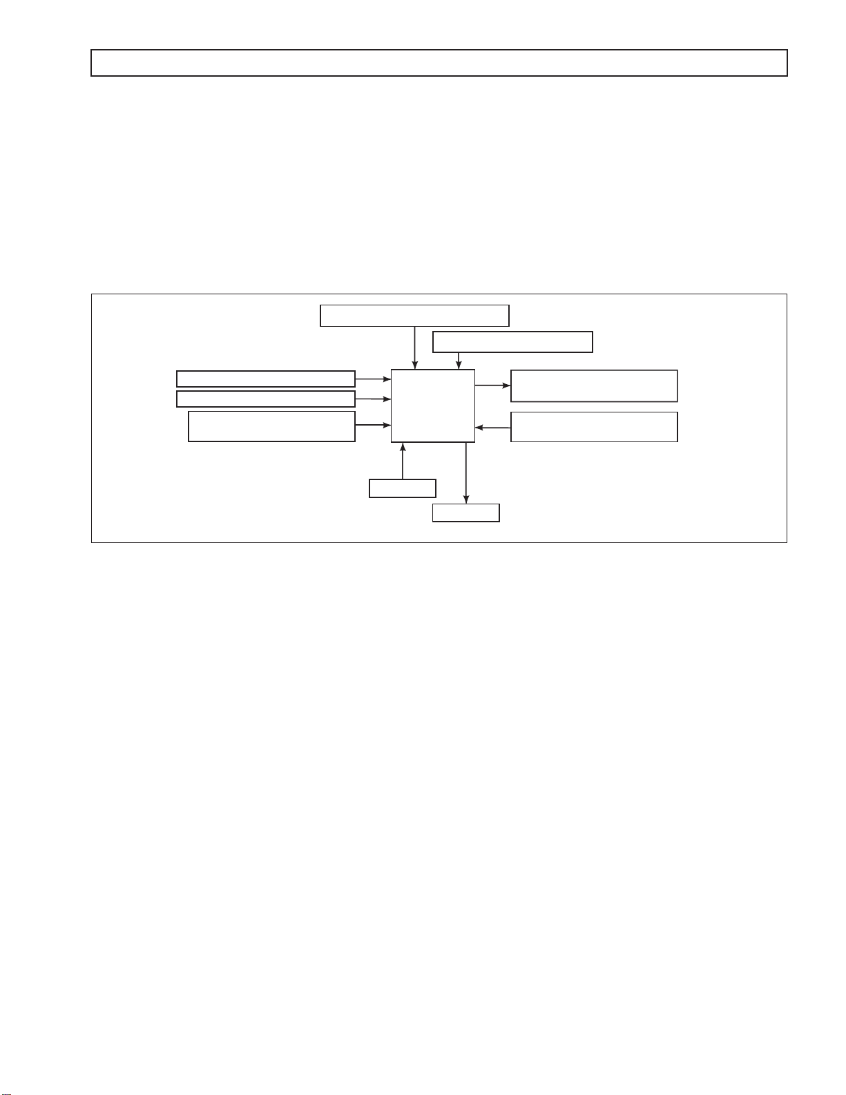
Figure 1–1 is a block diagram of the basic system inputs and outputs.
PRESSURE SWITCH MANIFOLD
SPEED SENSORS
THROTTLE POSITION SENSOR
VEHICLE/ENGINE
COMMUNICATION LINKS
th
Generation Controls system features closed-loop clutch control to
INTERNAL MODE SWITCH
SOLENOIDS
(VBS, ON/OFF)
TCM
TEMPERATURE SENSOR
(SUMP/ENGINE)
INPUTS
OUTPUTS
Figure 1–1. Transmission Control Module Block Diagram
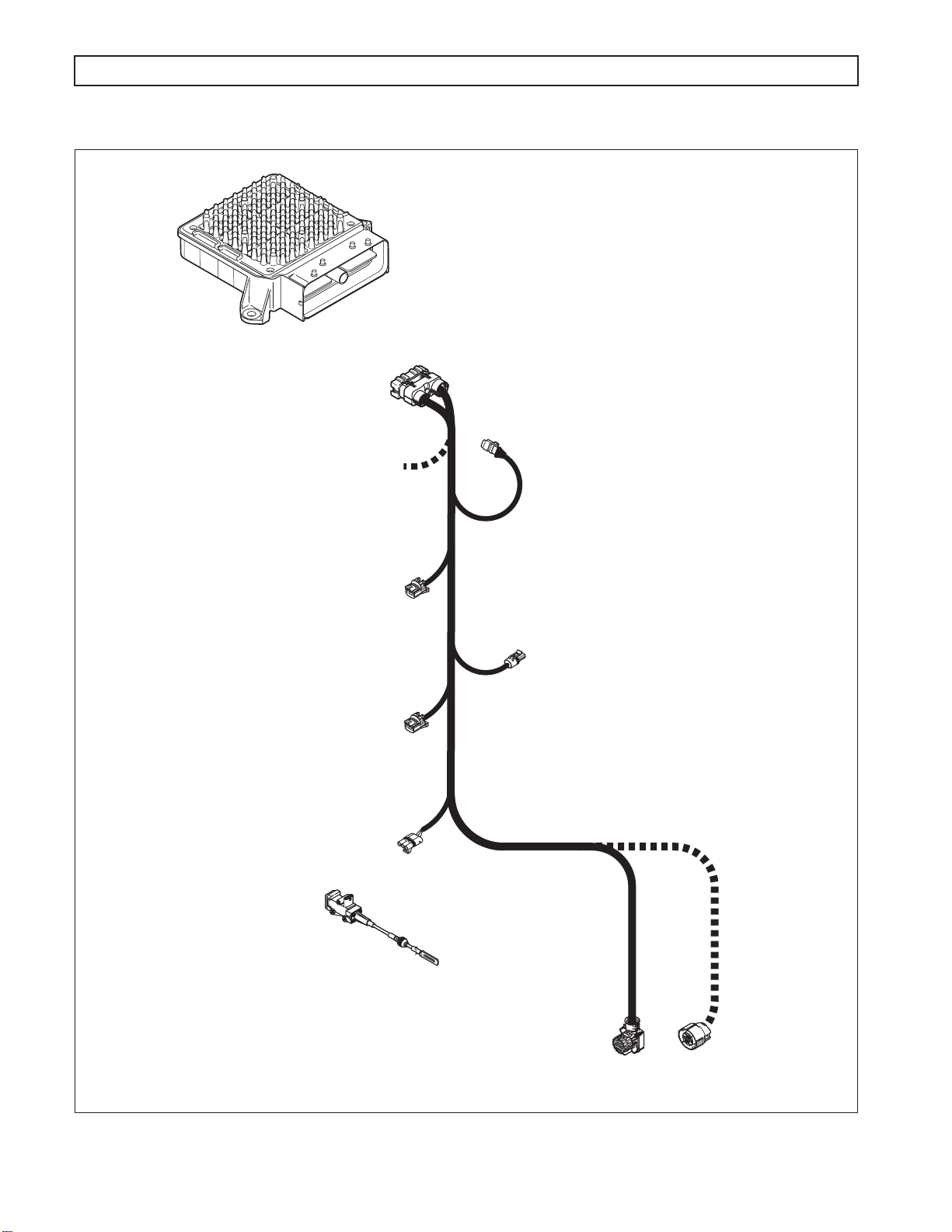
Figure 1–2 shows the electronic control components.
Electronic Controls consist of the following elements:
•
Remote 12V or 24V Transmission Control Module (TCM)
•
Throttle Position Sensor (TPS), electronic engine throttle data, or PWM signal
•
Speed Sensors—Input (Engine), Turbine, and Output
•
Control Valve Assembly (Electro-Hydraulic Valve Body)
•
Internal Mode Switch (IMS)
•
Pressure Switch Manifold (PSM)
•
Wiring Harnesses
NOTE: All external harnesses are OEM-supplied.
V05726.00.01
Copyright© 2007 Allison Transmission, Inc. 1–1
Page 10
1000 AND 2000 PRODUCT FAMILIES TROUBLESHOOTING MANUAL—ALLISON 4
GENERAL DESCRIPTION
TRANSMISSION
CONTROL
MODULE
(TCM)
TRANSMISSION
HARNESS
80-WAY
CONNECTOR
J1939
CONNECTOR
OEM SUPPLIED
INTERFACE HARNESS
th
GENERATION CONTROLS
ENGINE
SPEED SENSOR
CONNECTOR
TURBINE
SPEED SENSOR
CONNECTOR
THROTTLE POSITION
SENSOR (TPS)
CONNECTOR
(OPTIONAL)
THROTTLE
POSITION
SENSOR (TPS)
NOTE: Illustration is not to scale. Actual harness
configuration may differ from this illustration.
OUTPUT
SPEED SENSOR
CONNECTOR
24-WAY MAIN
TRANSMISSION
CONNECTOR
20-WAY
CONNECTOR
(OPTIONAL)
.
Figure 1–2. Electronic Control Components
1–2 Copyright© 2007 Allison Transmission, Inc.
V06475.03.00
Page 11
1000 AND 2000 PRODUCT FAMILIES TROUBLESHOOTING MANUAL—ALLISON 4
th
GENERATION CONTROLS
GENERAL DESCRIPTION
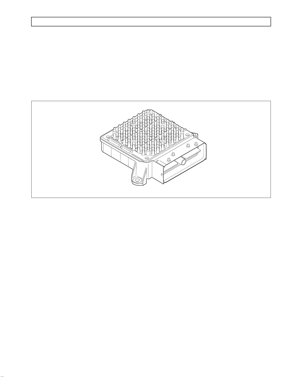
1–2. TRANSMISSION CONTROL MODULE (TCM)
The electronic control of the transmission is performed by a microcomputer. The microcomputer is an independent
controller and is referred to as a Transmission Control Module (TCM). TCMs are available in both 12V and 24V
configurations to match the configuration of the vehicle electrical system.
The TCM (refer to Figure 1–3) receives and processes signals from various switches and sensors. The TCM
determines shift sequences, shift timing, and clutch apply and release pressures. The TCM uses the information to
control transmission solenoids and valves, supply system status, and provide diagnostic information.
V09005.00.00
Figure 1–3. Transmission Control Module (TCM)
1–3. SHIFT SELECTOR
The vehicle is equipped with a lever-type shift selector (refer to Figure 1–4). In addition to the lever assembly
provided for the operator, other components associated with the shift selector are the manual selector valve in the
main control valve body and an Internal Mode Switch (IMS) mounted on the selector shaft inside the transmission
oil pan. Shift selector components (with the exception of the transmission selector shaft) are customer-supplied.
A. Shift Selector Range Positions
The operator chooses the transmission range by moving the selector lever to the appropriate gate
position (refer to Figure 1–4). When properly adjusted, the shifter gates prevent inadvertent shifting
between ranges and correspond to the internal transmission detent positions. A positive detent is
provided in the transmission to maintain the selector shaft in the selected position.
Copyright© 2007 Allison Transmission, Inc. 1–3
Page 12

P
R
N
OD
D , 2 , 1
M
1000 AND 2000 PRODUCT FAMILIES TROUBLESHOOTING MANUAL—ALLISON 4
GENERAL DESCRIPTION
SHIFT SELECTOR
Figure 1–4. Typical Lever-Type Shift Selector
th
GENERATION CONTROLS
P
R
N
OD
D
2
1
TOP VIEW
V06476.01.00
The TCM shift calibration determines the available forward ranges for each selector position.
Although specific installations vary, typical selector positions for the 1000 and 2000 Product Families
are:
—Park. Parking pawl or parking brake is engaged, if available. This position is not available on all
shift selectors.
—Reverse.
—Neutral. May be used when starting the engine and for stationary operations.
—Overdrive. The highest forward range used for normal driving. The transmission shifts to first
range for starting, then automatically upshifts through the ranges (as operating conditions permit)
until the highest range is attained.
—Forward Range. The transmission shifts to first range for starting. The range selected on the
shift selector is the highest range which will be attained during automatic shifting (on GM truck
applications, a position
is used for Tap Up/Tap Down functionality).
B. Manual Selector Valve
The manual shift selector shaft is attached to the manual selector valve within the transmission main
control valve body. The selector valve has three positions: reverse, neutral, and forward.
NOTE: For transmissions equipped with a P (Park) position, the selector valve remains in
the neutral position when the selector is moved to P (Park).
The neutral and reverse selector valve positions (refer to Appendix H—Hydraulic Schematics)
exhaust the C1 and C2 rotating clutches. By exhausting C1 and C2 clutches, forward range is
inhibited. This provides the capability for the operator to override the electronically commanded
ranges if neutral is required.
1–4 Copyright© 2007 Allison Transmission, Inc.
Page 13
1000 AND 2000 PRODUCT FAMILIES TROUBLESHOOTING MANUAL—ALLISON 4
GENERAL DESCRIPTION
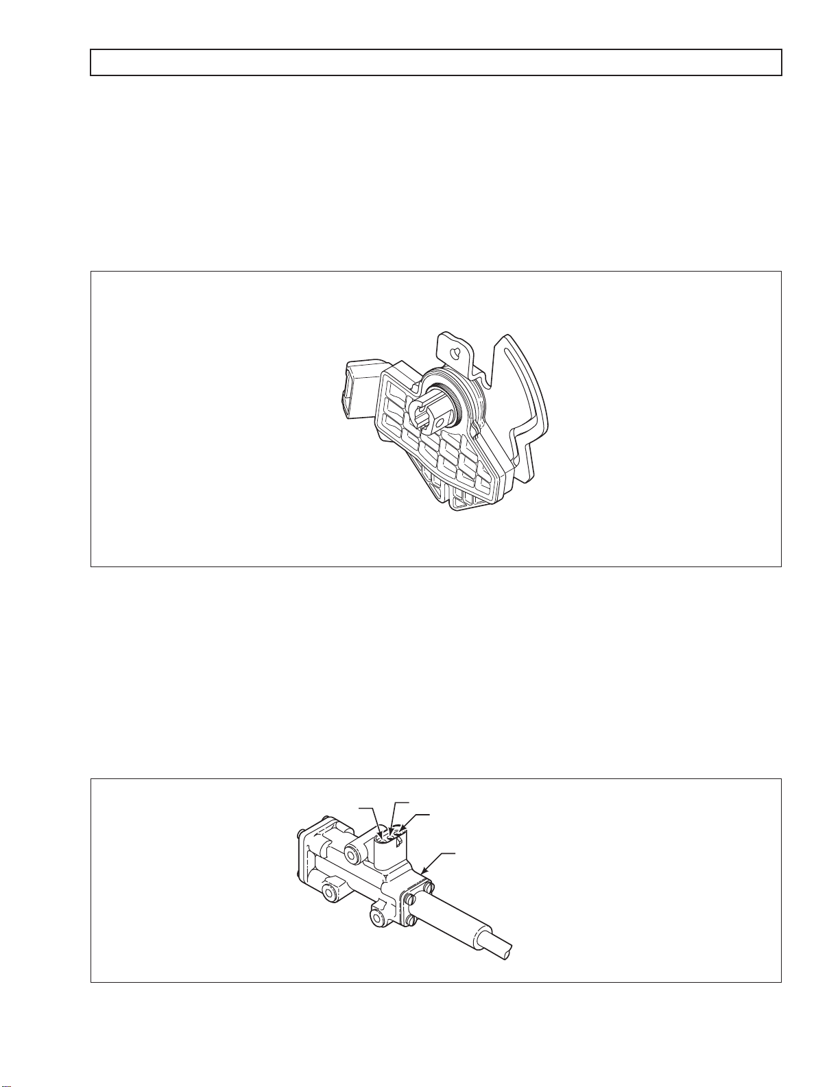
C. Internal Mode Switch (IMS)
An internally-mounted switch, commonly called an Internal Mode Switch or IMS (refer to Figure 1–5),
mounts inside the transmission oil pan at the shift selector shaft. The IMS detects the angular position of
the shift selector shaft. This position is communicated to the TCM so that certain vehicle control
functions can be coordinated with the position of the shift controls. The neutral signal output of the IMS
is typically used as confirmation that the transmission is in neutral before the engine starter is engaged.
th
GENERATION CONTROLS
V09076.00.00
Figure 1–5. Internal Mode Sensor (IMS)
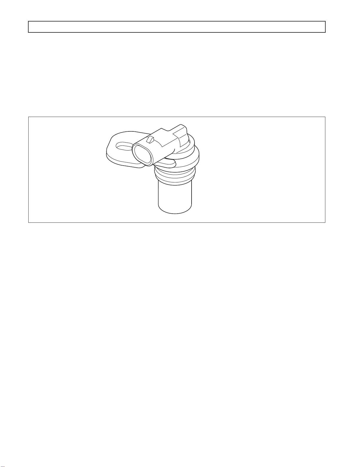
1–4. THROTTLE POSITION SENSOR (TPS)
The Throttle Position Sensor (TPS) can be mounted to the engine, chassis, or transmission. The TPS (refer to
Figure 1–6) contains a pull actuation cable and a potentiometer. One end of the cable is attached to the engine fuel
lever and the other, inside a protective housing, to the TPS potentiometer. Output voltage from the TPS is directed
to the TCM through the external harness. The voltage signal indicates the throttle position and, in combination with
other input data, determines shift timing.
A
B
C
THROTTLE POSITION
SENSOR (TPS)
V00628.01
Figure 1–6. Throttle Position Sensor (TPS)
Copyright© 2007 Allison Transmission, Inc. 1–5
Page 14
1000 AND 2000 PRODUCT FAMILIES TROUBLESHOOTING MANUAL—ALLISON 4
th
GENERATION CONTROLS
GENERAL DESCRIPTION
1–5. SPEED SENSORS
There are three speed sensors available for use with 1000 and 2000 Product Families transmissions: the input
(engine) speed sensor, the turbine speed sensor, and the output speed sensor (refer to Figure 1–7). The speed
sensors provide rpm information to the TCM. The speed ratios between the various sensors allow the TCM to
determine the transmission operating range. Speed sensor information is also used to control the timing of clutch
apply pressures, resulting in the best possible shift quality.
V04736
Figure 1–7. Typical Speed Sensor
The speed sensors are variable reluctance devices which convert mechanical motion to an AC voltage. Each sensor
consists of a wire coil wrapped around a pole piece that is adjacent to a permanent magnet. These elements are
contained in a housing which is mounted adjacent to a rotating ferrous member (such as a gear tooth). Two signal
wires extend from one end of the housing and an exposed end of the pole piece is at the opposite end of the
housing. The permanent magnet produces lines of flux around the pole piece. As a ferrous object (such as a gear
tooth) approaches and passes through the gap at the end of the pole piece, an AC voltage pulse is induced in the
wire coil. The TCM calculates the frequency of these AC pulses and converts it to a speed value. The AC voltage
generated varies from 150mV at low speed to 15V at high speed. The signal wires from the sensor are formed as
twisted pairs to cancel magnetically induced fields. The cable is also shielded to protect from voltage-related fields.
Noise from other sources is eliminated by using two-wire differential inputs at the TCM.
NOTE: Do not rotate the speed sensor in the retaining bracket. Orientation is fixed, and if changed, may cause
improper operation.
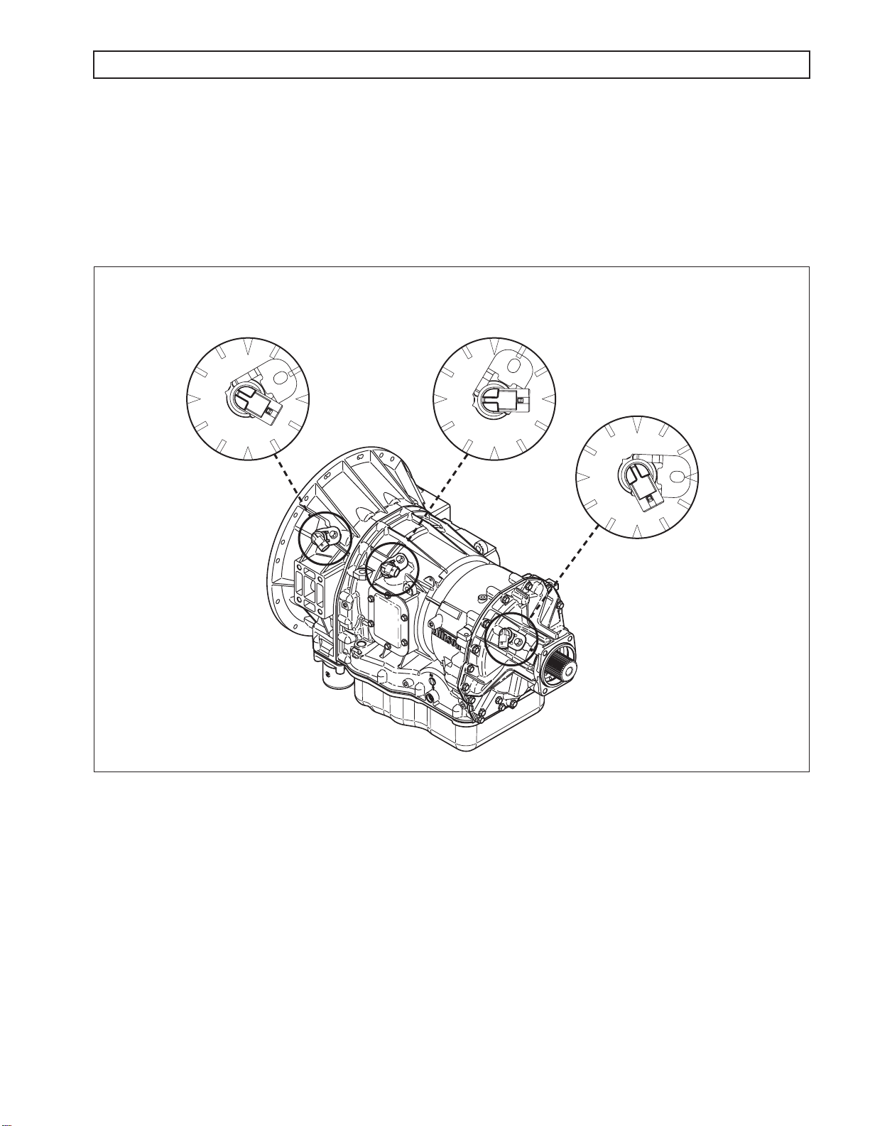
A. Input (Engine) Speed Sensor
The input speed sensor is externally mounted in the torque converter housing directed at the ribs
protruding from the torque converter. The input speed sensor connector should be positioned at
approximately four o’clock, as viewed from the left side of the transmission (refer to Figure 1–8).
B. Turbine Speed Sensor
The turbine speed sensor is externally mounted in the main housing directed at the tone wheel or PTO
drive gear attached to the rotating clutch module. The turbine speed sensor connector should be
positioned at approximately three o’clock, as viewed from the left side of the transmission (refer to
Figure 1–8).
1–6 Copyright© 2007 Allison Transmission, Inc.
Page 15
1000 AND 2000 PRODUCT FAMILIES TROUBLESHOOTING MANUAL—ALLISON 4th GENERATION CONTROLS
GENERAL DESCRIPTION
C. Output Speed Sensor
The output speed sensor is externally mounted in the rear cover and directed at the teeth of a tone
wheel splined to and rotating with the output shaft. The output speed sensor connector should be
positioned at approximately five o’clock, as viewed from the left side of the transmission (refer to
Figure 1–8).
ENGINE SPEED
SENSOR CONNECTOR
ORIENTATION = 4 o'clock
TURBINE SPEED
SENSOR CONNECTOR
ORIENTATION = 3 o'clock
OUTPUT SPEED
SENSOR CONNECTOR
ORIENTATION = 5 o'clock
V06457.01.00
Figure 1–8. Speed Sensor Connector Orientation
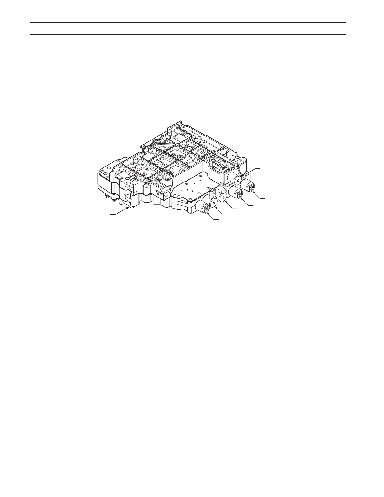
1–6. CONTROL VALVE ASSEMBLY
The hydraulic control valve assembly (Figure 1–9) governs fluid flow to the clutches (including the torque
converter clutch). Solenoids, actuated by the TCM, control valve movement.
The control valve assembly consists of two components, the main valve body and the control valve body. The main
valve body contains the pressure control valves (PCV), the TCC valve, the exhaust backfill valve, and the control
main relief valve. The shift valve body contains the shift valves, the control main pressure valve, and the manual
selector valve. The control valve assembly attaches to the bottom of the gearbox module and is enclosed by the oil
pan. An internal wiring harness connects the solenoids and Pressure Switch Manifold (PSM) to the main
transmission connector and external wiring harness.
Copyright© 2007 Allison Transmission, Inc. 1–7
Page 16
1000 AND 2000 PRODUCT FAMILIES TROUBLESHOOTING MANUAL—ALLISON 4th GENERATION CONTROLS
GENERAL DESCRIPTION
A. Main Modulation
Main pressure is reduced by utilizing an on/off Main Mod solenoid that is located in the control valve
body assembly. The Main Mod solenoid body is bolted to the main valve body. Main pressure will be
reduced under various conditions such as low throttle, low torque, low engine speeds, and low output
speeds. The primary benefit of modulating main pressure is to increase cooler flow at low engine speeds.
SS1
PCS1
PCS2
SS3
MAIN MOD
TCC
SS2
V07476.02.01
Figure 1–9. Control Valve Assembly
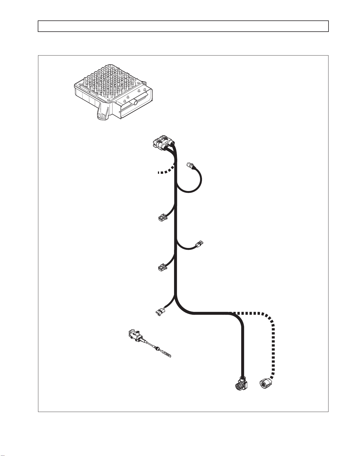
1–7. WIRING HARNESS
A. External Wiring Harness
The external wiring harness (refer to Figure 1–10) requirements are typically met through the use of a
single harness with one branch connecting the TCM to the transmission, throttle position sensor, IMS,
and speed sensors; another branch connecting the TCM to Allison DOC™ For PC–Service Tool and
other vehicle interfaces. All wiring harnesses and mating connectors are OEM-supplied.
NOTE: Repair parts for the external harness and external harness components must be obtained through the
vehicle OEM. The OEM is responsible for warranty on these parts.
1–8 Copyright© 2007 Allison Transmission, Inc.
Page 17
1000 AND 2000 PRODUCT FAMILIES TROUBLESHOOTING MANUAL—ALLISON 4th GENERATION CONTROLS
GENERAL DESCRIPTION
TRANSMISSION
CONTROL
MODULE
(TCM)
TRANSMISSION
HARNESS
80-WAY
CONNECTOR
J1939
CONNECTOR
OEM SUPPLIED
INTERFACE HARNESS
ENGINE
SPEED SENSOR
CONNECTOR
TURBINE
SPEED SENSOR
CONNECTOR
THROTTLE POSITION
SENSOR (TPS)
CONNECTOR
(OPTIONAL)
THROTTLE
POSITION
SENSOR (TPS)
NOTE: Illustration is not to scale. Actual harness
configuration may differ from this illustration.
OUTPUT
SPEED SENSOR
CONNECTOR
24-WAY MAIN
TRANSMISSION
CONNECTOR
20-WAY
CONNECTOR
(OPTIONAL)
V06475.03.00
Figure 1–10. Typical External Wiring Harnesses
Copyright© 2007 Allison Transmission, Inc. 1–9
Page 18
1000 AND 2000 PRODUCT FAMILIES TROUBLESHOOTING MANUAL—ALLISON 4th GENERATION CONTROLS
GENERAL DESCRIPTION
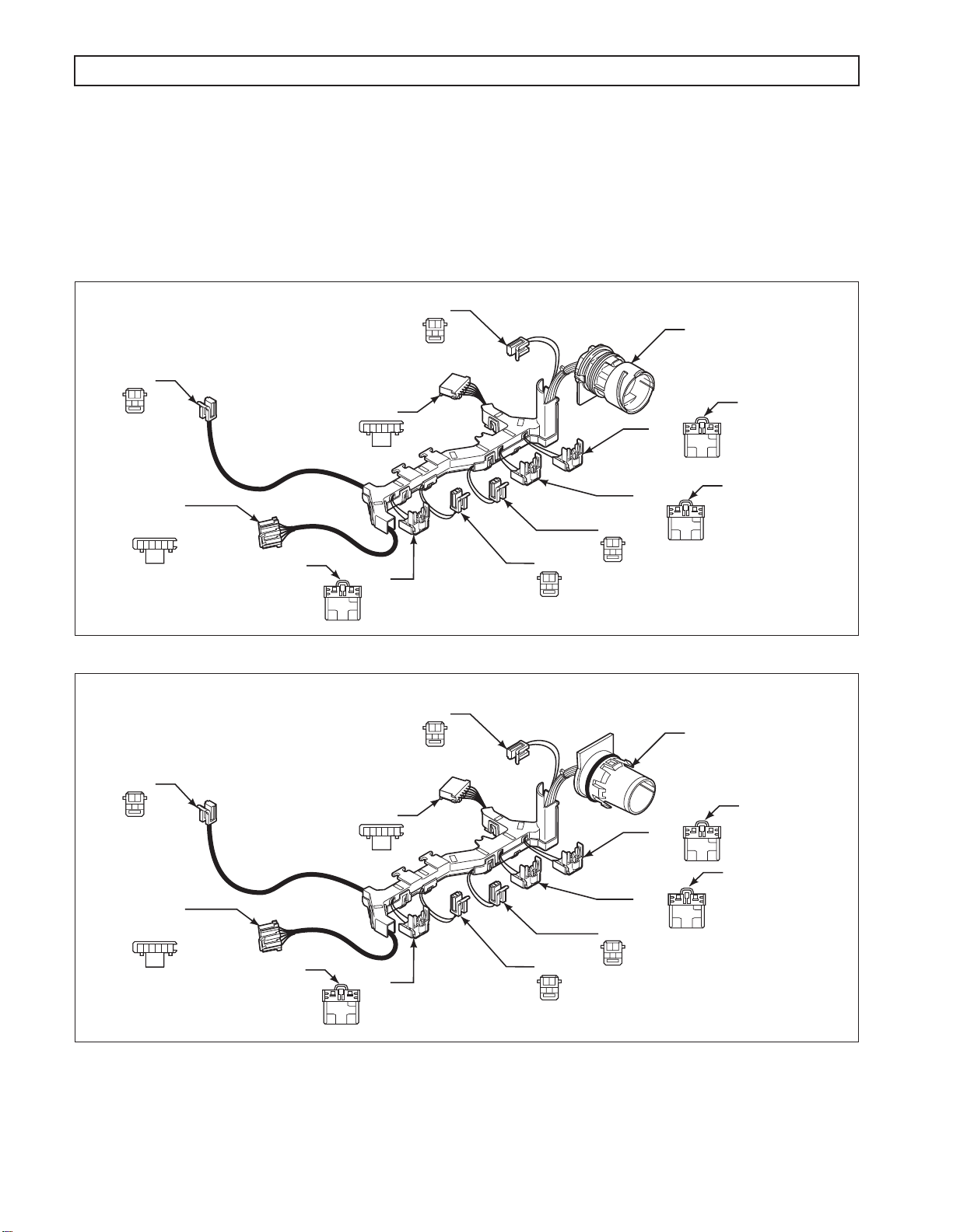
B. Internal Wiring Harness
An internal wiring harness (refer to Figure 1–11 and Figure 1–12) connects the shift solenoids (SS1,
SS2, SS3), pressure control solenoids (PCS1, PCS2), torque converter clutch solenoid (TCC), internal
mode switch (IMS), pressure switch manifold (PSM), and temperature sensor to the external harness
leading to the TCM.
MAIN
MOD
AB
GRAY
IMS
INTERNAL
MODE
SWITCH
A B C D E F
MAIN
MOD
AB
GRAY
SS1
AB
GRAY
PSM
A B C D E F
PCS1
PCS2
SS3
AB
LOCKARM
TCC
21
SS2
AB
GRAY
GRAY
Figure 1–11. Typical Internal Wiring Harness (24-Way Connector)
SS1
AB
GRAY
PSM
A B C D E F
PCS1
MAIN
TRANSMISSION
CONNECTOR
LOCKARM
21
LOCKARM
21
V08975.00.00
MAIN
TRANSMISSION
CONNECTOR
LOCKARM
21
IMS
INTERNAL
MODE
SWITCH
A B C D E F
LOCKARM
TCC
21
SS2
AB
GRAY
Figure 1–12. Typical Internal Wiring Harness (20-Way Connector for GM Applications Only)
1–10 Copyright© 2007 Allison Transmission, Inc.
SS3
AB
GRAY
PCS2
LOCKARM
21
V08974.00.00
Page 19
1000 AND 2000 PRODUCT FAMILIES TROUBLESHOOTING MANUAL—ALLISON 4th GENERATION CONTROLS
J 47275
J 47276
J 47277
J 47278
GENERAL DESCRIPTION
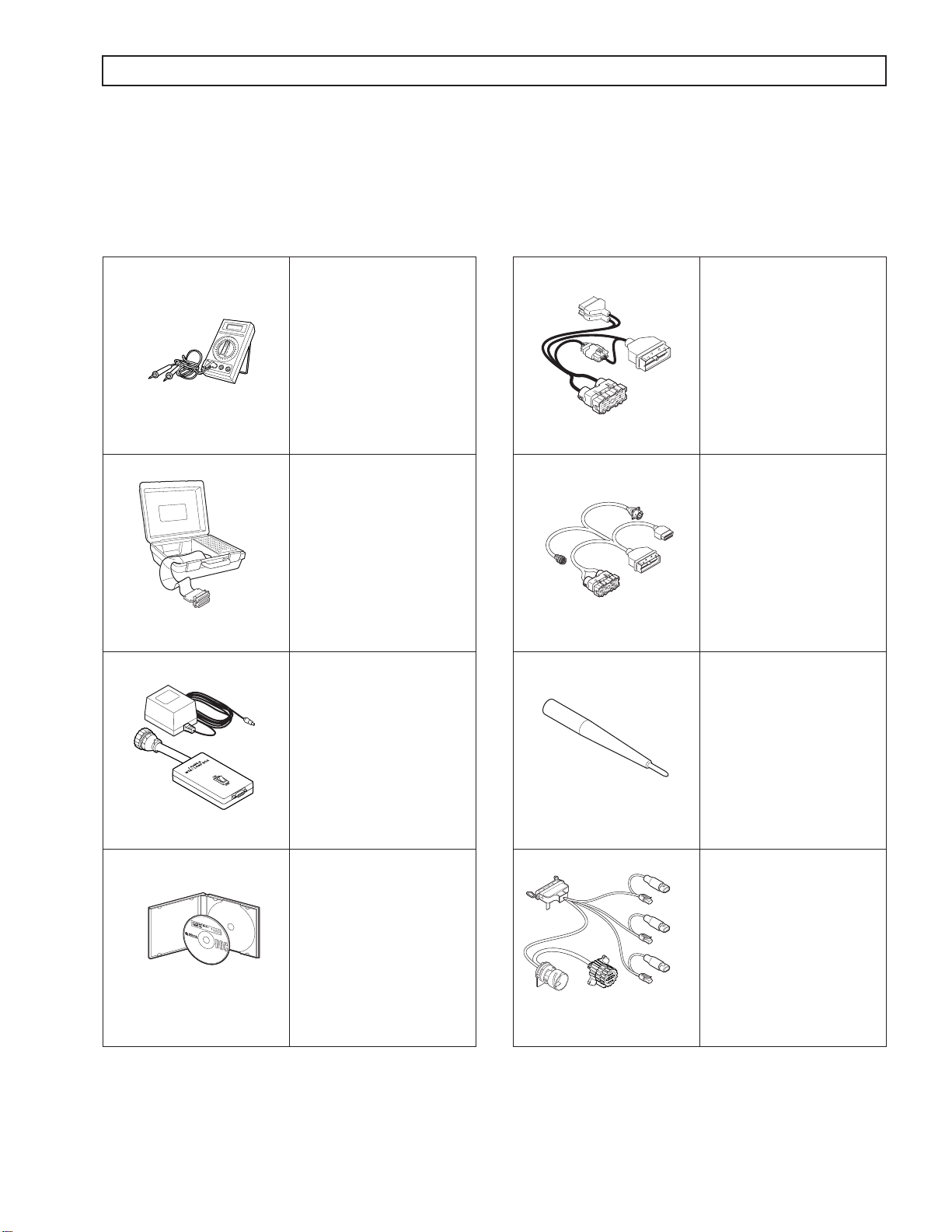
1–8. SPECIAL ELECTRONIC/ELECTRICAL TOOLS
All tools listed are essential for overhaul, maintenance, and/or recalibration of the 1000 and 2000 Product Families
electronic and electrical systems. The tools listed below are available for purchase from SPX/Kent-Moore.
Table 1–1. Essential Tools
3 4 of 9 D I G I T A L M U L T I M E T E R
40
50
100
500
200
300
300
900
400
600
2
5
7
200
500
300
600
400
500
500
700
600
x
COM
abcde
A
xyz ab
10 A
abcde
xyz ab
m
ultim
eter
J 34520-A
Digital
Volt/Ohmmeter
J 47275
TCM Breakout
Harness Adapter
J 39700
J 42455-A
J 39700
Univeral Breakout Box
J 42455-A
Load Box
J 44950
Allison DOC™ For
PC–Service Tool
J 47276
“T” Breakout and TCM
Reflashing Harness
J 47277
Terminal Probe
NOTE: J 47277 is now
included in the J 39197-A
Kit.
J 47278
1000 and 2000 Product
Families Breakout Harness
J 44950
Copyright© 2007 Allison Transmission, Inc. 1–11
Page 20
1000 AND 2000 PRODUCT FAMILIES TROUBLESHOOTING MANUAL—ALLISON 4th GENERATION CONTROLS
J 47949
J 47139
GENERAL DESCRIPTION
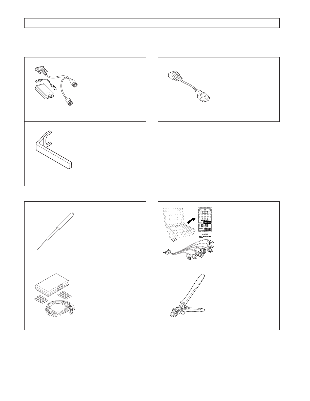
Table 1–1. Essential Tools (cont’d)
J 47943
J 47944
J 47943
DPA4 USB
Translator Device
J 47944
1000 and 2000 Product
Families Main
Transmission Connector
Removal Tool
Table 1–2. Available Tools
J 38125-12A
Terminal Remover
(80-way connector)
GM P/N: 12094429
J 47949
GMLAN Cable
J 44722-3 Overlay
J 44722-3 Cable
NOTE: J-44722-3 overlay
is for pick-up truck use
only.
J 38125-12A
J 39197-A
Jumper Kit
J 39197-A
1–12 Copyright© 2007 Allison Transmission, Inc.
J 47139
Crimper
Page 21

1000 AND 2000 PRODUCT FAMILIES TROUBLESHOOTING MANUAL—ALLISON 4th GENERATION CONTROLS
SECTION 2—DEFINITIONS AND ABBREVIATIONS
2–1. CHECK TRANS LIGHT
The electronic control system is programmed to inform the operator of a problem with the transmission system and
automatically take action to protect the operator, vehicle, and transmission. To do this, the TCM turns on the
CHECK TRANS light on the instrument panel, which notifies the operator that a Diagnostic Trouble Code (DTC)
has been stored.
Each time the engine is started, the TCM will illuminate the CHECK TRANS light, then turn it off after a few
seconds. This is a circuit check to verify that the lamp and wiring are in proper working order. Illumination of the
CHECK TRANS light at any time after start-up indicates that the TCM has set a DTC. Allison DOC™ For PC–
Service Tool is used to verify that the TCM has set a DTC (refer to Section 2–2). While the CHECK TRANS light
is on, upshifts and downshifts may be restricted and direction changes (D–R, R–D) may not occur. The torque
converter clutch is inhibited when transmission shifting is restricted or during any critical transmission
malfunction.
The 1000 and 2000 Product Families transmissions DTCs are latching DTCs. When a failure condition is detected,
the DTC set by the TCM remains active for the entire time the ignition is on. When the ignition is turned off and
then on again, the transmission DTCs will reset and the TCM will recheck for the failure condition. If the failure
condition is not present, the previously set DTC will remain in history; the CHECK TRANS light will turn off
after the circuit check, and the transmission will function normally unless another failure occurs. This feature
allows the vehicle to be driven to a service outlet.
2–2. RANGE INHIBIT RESPONSES
The range inhibit feature is a function of the TCM logic. The TCM senses when certain input variables are
exceeded and takes action to prevent transmission damage. The TCM inhibits neutral-to-range shifts and
illuminates a light on the dash when the inhibit is active.
Listed below are three variables that, when exceeded, cause inhibited shifts (with thresholds listed).
• Engine speed above 1000 rpm
• Throttle setting above 40 percent
• Output speed above 225 rpm
There are two levels of the special logic inhibits.
• Self-clearing inhibit—This inhibit clears itself if one of the above conditions is not present after a
calibrated time. This is three seconds in the case of medium-duty vehicles. If the shift inhibit is active,
but not latched, the bulb will stay lit until self-cleared.
• Latching inhibit — This inhibit latches when one of the conditions listed above is still present after a
calibrated time. This is above three seconds for medium duty vehicles. To clear a latching inhibit, move
the selector into any other position than the one originally selected.
2–3. ALLISON DOC™ FOR PC–SERVICE TOOL INHIBITS
If an inhibit has occurred since the last DTC was cleared, the inhibit state will indicate ON and will stay ON until
the next manual DTC clear with Allison DOC™ For PC–Service Tool. These latched inhibits do not turn OFF
after a specified number ignition cycles.
Copyright© 2007 Allison Transmission, Inc. 2–1
Page 22

1000 AND 2000 PRODUCT FAMILIES TROUBLESHOOTING MANUAL—ALLISON 4th GENERATION CONTROLS
DEFINITIONS AND ABBREVIATIONS
The range inhibit light will illuminate and/or an inhibited state will be shown on Allison DOC™ For PC–Service
Tool when the transmission is inhibited to Neutral for the following reasons:
• Low Main Pressure
If the transmission pressure switches do not indicate transmission pressurized at start-up, shifts-to-range
may be inhibited and the range inhibit light will illuminate. Allison DOC™ For PC–Service Tool will
indicate an active inhibit.
Common causes are transmission low on fluid, transmission filter has just been changed, or pan has
been removed and fluid recently drained.
May produce DTC P0701.
• Transfer Case Neutral
If the transfer case is shifted into neutral while the transmission is in drive or reverse at a speed above
idle, the transmission will continue to command range until the output speed is reduced to a point where
neutral range is commanded. The range inhibit light will illuminate and Allison DOC™ For PC–Service
Tool will indicate an active inhibit.
• Diagnostic Active
This indicates that an active diagnostic code was set and the driver attempted a range selection that was
inhibited. In some failure modes, reverse cannot and will not be commanded. If reverse is selected
during these failure modes a range inhibit light will illuminate in reverse.
During diagnostic responses, Neutral-to-Range Inhibits and Direction Change Inhibits continue to
operate, but they may latch under certain conditions. In these cases, shutting down ignition and waiting
for at least 5 seconds before restarting will clear the inhibit condition. Allison DOC™ For PC–Service
Tool will indicate an active inhibit.
• Auto Neutral for PTO
Neutral-to-Drive and Neutral-to-Reverse shifts will be inhibited to neutral and Allison DOC™ For
PC–Service Tool will show an inhibited state when TCM detects that auto neutral function input is
active.
• Reverse Enable
Neutral-to-Reverse shifts will be inhibited to neutral and Allison DOC™ For PC–Service Tool will
show an inhibited state when no input is detected from dash or floor mounted reverse enable switch
when selecting reverse range. Allison DOC™ For PC–Service Tool will indicate an active inhibit.
This function is only used in European transit and tour buses applications.
• Refuse Packer Step Switch
Transmission operation is limited to only 1st range. Neutral-to-reverse shifts will be inhibited to neutral
and Allison DOC™ For PC–Service Tool will show an inhibited state when input is detected from a step
switch indicating that personnel is present on rear step platform.
• Auxiliary Function Range Inhibit
Neutral-to-Drive and Neutral-to-Reverse shifts will be inhibited to neutral and Allison DOC™ For
PC–Service Tool will show an inhibited state when input is detected from an auxiliary switch or device.
This inhibit will remain active until the auxiliary switch input is shut off and range is reselected.
2–2 Copyright© 2007 Allison Transmission, Inc.
Page 23

1000 AND 2000 PRODUCT FAMILIES TROUBLESHOOTING MANUAL—ALLISON 4th GENERATION CONTROLS
DEFINITIONS AND ABBREVIATIONS
• PTO Neutral Lockup
Allison DOC™ For PC–Service Tool will show an inhibited state when Neutral Lockup is active and
range shifts are being inhibited to neutral. When the selector is moved, lockup is released and the inhibit
clears.
• Engine Speed
Neutral-to-Drive and Neutral-to-Reverse shifts will be inhibited to neutral and the range inhibit light
will illuminate if the Engine Speed is greater than a calibrated value (1400 rpm for medium duty
non-emergency vehicles). Allison DOC™ For PC–Service Tool will indicate an active inhibit.
• Output Speed
Reverse-to-Drive, Drive-to-Reverse, and Neutral-to-Reverse shifts initiated above 300 rpm of output
speed will be inhibited to neutral and the range inhibit light will illuminate. Allison DOC™ For PC–
Service Tool will indicate an active inhibit.
• Throttle
Reverse-to-Drive, Drive-to-Reverse, Neutral-to-Drive, and Neutral-to-Reverse shifts where throttle
position is greater then 25 percent will be inhibited to neutral and the range inhibit light will illuminate.
Allison DOC™ For PC–Service Tool will indicate an active inhibit.
• IMS Function or Alignment
Reverse-to-Drive, Drive-to-Reverse, Neutral-to-Drive, and Neutral-to-Reverse shifts will be inhibited to
neutral and the range inhibit light will illuminate when an IMS failure or misalignment is detected. A
common cause would be an error in the four-bit IMS input signal that is sent to the TCM.
Allison DOC™ For PC–Service Tool will indicate an active inhibit.
• IMS PS4 Disagree
Reverse-to-Drive, Drive-to-Reverse, Neutral-to-Drive, and Neutral-to-Reverse shifts will be inhibited to
neutral and the range inhibit light will illuminate when the Pressure Switch 4 (PS4) status is in the
incorrect state when compared to the IMS state. Allison DOC™ For PC–Service Tool will indicate an
active inhibit. This inhibit may be caused by a defective IMS, PSM, or valve body concerns.
• MSV Mis-Alignment/Unable to detect ratio after shift to range
If the range verification test fails to detect turbine speed pull-down or valid gear ratio when the Manual
Selector Valve (MSV) shifts to either forward or reverse range from neutral, the transmission will shift
back to a neutral condition and the range inhibit light will illuminate.
Conditions that may cause this include: Attempts to shift the transmission from Neutral-to-Drive or
Neutral-to-Reverse with the transfer case in neutral; transmission low on fluid; misadjustment in the
IMS or Selector Linkage; turbine or output speed sensor failure that may prevent the pull down test/ratio
test from passing; solenoid A or B hydraulically failures; and possibly failed range clutch (C1 or C5 for
1st, C3 or C5 for Reverse).
Allison DOC™ For PC–Service Tool will indicate an active inhibit response.
• Wheel Spin or Lock
When the TCM detects that wheel lock or spin is occurring, the TCC is disengaged and a lock-to-range
response is commanded for 6 seconds. Allison DOC™ For PC–Service Tool will indicate an active
inhibit response.
Copyright© 2007 Allison Transmission, Inc. 2–3
Page 24
1000 AND 2000 PRODUCT FAMILIES TROUBLESHOOTING MANUAL—ALLISON 4th GENERATION CONTROLS
DEFINITIONS AND ABBREVIATIONS
2–4. ALLISON DOC™ FOR PC–SERVICE TOOL
Allison DOC™ For PC–Service Tool v5.0.0 (or later) is available through Kent-Moore Heavy-Duty Division.
®
When installed on a Windows
receives data to and from the TCM via the vehicle data communications link, processes the data, and displays
appropriate information. Use Allison DOC™ For PC–Service Tool during installation checkout and
troubleshooting.
For more details on Allison DOC™ For PC–Service Tool features, refer to the User Guide for Allison DOC™ For
PC–Service Tool Version 5.0.0, GN3433EN.
PC, the Allison DOC™ For PC–Service Tool (refer to Figure 2–1) transmits and
V05490
Figure 2–1. Allison DOC™ For PC–Service Tool
2–4 Copyright© 2007 Allison Transmission, Inc.
Page 25

1000 AND 2000 PRODUCT FAMILIES TROUBLESHOOTING MANUAL—ALLISON 4th GENERATION CONTROLS
DEFINITIONS AND ABBREVIATIONS
2–5. ABBREVIATIONS
A/N Assembly Number
ABS Anti-lock Brake System—OEM-provided means to detect and prevent wheel stoppage to
enhance vehicle handling. Retarder and engine brakes will not apply when ABS is active.
Amp Ampere—Unit of electrical current
CAN Controller Area Network—A network for all SAE J1939 communications in a vehicle
(engine, transmission, diagnostics, ABS, etc.)
CC Calibration Compatibility—First two digits of the CIN
CIN Calibration Identification Number—Used to identify transmission controls software level
CMC Customer Modifiable Constants
CT Closed Throttle
DNA Does Not Adapt—Adaptive shift control is disabled.
DNS DO NOT SHIFT—Refers to the DO NOT SHIFT diagnostic response during which the
CHECK TRANS light is illuminated and the transmission will not shift and will not
respond to the Shift Selector.
DTC Diagnostic Trouble Code
DVOM Digital volt/ohmmeter
ECM Engine Controller Module—Available on electronically-controlled engines—provides
some relevant data to TCM.
EMI ElectroMagnetic Interference
GPI General Purpose
condition.
GPO General Purpose Output—Output signal from the TCM to control vehicle components
(such as PTOs, backup lights, etc.) or allow a special operating mode or condition.
IMS Internal Mode Switch
IPC Instrument Panel Controller
J 1939 High-speed vehicle serial data communications standard.
LED Light-Emitting Diode—Electronic device used for illumination.
LRTP Low-Range Torque Protection—A feature limiting engine torque in lower ranges and
reverse to protect the transmission from damage.
NVL Neutral Very Low—The TCM has sensed turbine speed below 150 rpm. This is usually
caused by a dragging C1 or C3 clutch or a failed turbine speed sensor. When attained, the
C4 and C5 clutches are applied to lock the transmission output.
OBD II On Board Diagnostics Second generation. EPA mandated specification for vehicle
diagnostics.
Input—Input signal to the TCM to request a special operating mode or
OEM Original Equipment Manufacturer—Maker of vehicle or equipment.
Ohm Unit of electrical resistance.
PC Personal Computer
PCCS Production Calibration Configuration System
Copyright© 2007 Allison Transmission, Inc. 2–5
Page 26

1000 AND 2000 PRODUCT FAMILIES TROUBLESHOOTING MANUAL—ALLISON 4th GENERATION CONTROLS
DEFINITIONS AND ABBREVIATIONS
2–5. ABBREVIATIONS (cont’d)
PCM Powertrain Controller Module—Electronic device used on some vehicles.
PCS Pressure Control Solenoid
PCV Pressure Control Valve
PDM Parallel Data Module
PPC Pressure Proportional to Current solenoid. Solenoid control of clutch pressure is
proportional to the current being supplied to the solenoid.
PROM Programmable Read Only Memory
PS Pressure Switch
PSM Pressure Switch Manifold—Part of transmission control system located inside the oil pan.
PTO Power Takeoff
PWM Pulse Width Modulation
RFI Radio Frequency Interference
RPR Return to Previous Range—Diagnostic response in which the transmission is commanded
to return to previously commanded range.
SEM Shift Energy Management—Allows the TCM to request torque reduction from the ECM
during upshifts for increased clutch life.
SOL OFF All SOLenoids OFF
SS Shift
SV Shift Valve
TBC Truck Body Controller
TCC Torque Converter Clutch
TCM Transmission Control Module (also commonly referred to as the “computer”)
TFT Transmission Fluid Temperature—Data provided by thermistor that is part of the PSM.
TPS Throttle Position Sensor—Potentiometer for signaling the position of the engine fuel
V Version—Abbreviation used in describing TCM software levels.
VBS Variable Bleed Solenoid—Another name for Pressure Proportional to Current (PPC)
VDC Volts Direct Current (DC)
VIW Vehicle Interface Wiring—Interfaces TCM programmed input and output functions with
Volt Unit of electrical force
Solenoid
control lever.
solenoid. Solenoid control of clutch pressure is proportional to the current being supplied
to the solenoid.
the vehicle wiring.
VOM Volt/ohmmeter
WOT Wide Open Throttle
∞ Infinity—Condition of a circuit with higher resistance than can be measured; effectively an
open circuit.
2–6 Copyright© 2007 Allison Transmission, Inc.
Page 27

1000 AND 2000 PRODUCT FAMILIES TROUBLESHOOTING MANUAL—ALLISON 4th GENERATION CONTROLS
SECTION 3—BASIC KNOWLEDGE
3–1. BASIC KNOWLEDGE REQUIRED
To service 1000 and 2000 Product Families Allison 4th Generation Controls, the technician must understand basic
electrical concepts. Technicians need to know how to use a digital volt/ohmmeter (DVOM) to make resistance and
continuity checks. Most troubleshooting checks consist of checking resistance and continuity, and checking for
shorts between wires and to ground. The technician should be able to use jumper wires and breakout harnesses and
connectors. Technicians unsure of making the required checks should ask questions of experienced personnel or
find instruction.
The technician should also have the mechanical aptitude required to connect pressure gauges or transducers to
identified pressure ports used in the troubleshooting process. Pressure tap locations and pressure values are shown
in Appendix B—Main Pressure Check Procedure.
Input power, ground, neutral start circuitry, etc., can cause problems with electronic controls or vehicle functioning
th
and may not generate a DTC. A working knowledge of 1000 and 2000 Product Families Allison 4
Controls vehicle installation is necessary in troubleshooting installation-related problems.
Refer to Section 7 for information concerning performance complaints (non-DTC) troubleshooting. A complete
wiring schematic is shown in Appendix J. Refer to the 1000 and 2000 Product Family Tech Data for information
concerning electronic controls installation and the Installation Checklist. Reliable transmission operation and
performance depend upon a correctly installed transmission. For proper installation, review the Installation
Checklist in the 1000 and 2000 Product Family Tech Data, available on the extranet under Engineering at
www.allisontransmission.com.
Generation
3–2. USING THE TROUBLESHOOTING MANUAL
Use this manual as an aid to troubleshooting the 1000 and 2000 Product Families Allison 4th Generation Controls.
Every possible problem and its solution cannot be encompassed by any manual. However, this manual does
provide a starting point from which most problems can be resolved.
Once a problem solution is discovered in the manual do not look further for other solutions. It is necessary to
determine
why a problem occurred. The root cause of a problem as well as the symptom must be corrected to
ensure trouble free operation. For example, taping a wire that has been rubbing on a frame rail will not correct the
problem unless the rubbing contact is eliminated.
3–3. SYSTEM OVERVIEW
1000 and 2000 Product Families Allison 4th Generation Control functions are controlled by the TCM. The TCM
reads shift selector range selection, output speed, and throttle position to determine when to command a shift.
When a shift occurs, the TCM monitors turbine speed, output speed, and throttle position to control the oncoming
and off-going clutches during the shift.
When the TCM detects an electrical fault, it logs a DTC indicating the faulty circuit and may alter the transmission
operation to prevent or reduce damage.
When the TCM detects a non-electrical problem while trying to make a shift, the TCM may try that shift a second
or third time before setting a DTC. Once that shift has been retried, and a fault is still detected, the TCM sets a
DTC and holds the transmission in a fail-to-range mode of operation.
Copyright© 2007 Allison Transmission, Inc. 3–1
Page 28

1000 AND 2000 PRODUCT FAMILIES TROUBLESHOOTING MANUAL—ALLISON 4th GENERATION CONTROLS
BASIC KNOWLEDGE
The 1000 and 2000 Product Families transmission utilizes “clutch to clutch” shift control to achieve range
changes. In every case (except shifts to or from neutral), one clutch is exhausted and another applied to make a
range shift. The “handoff” between exhausting and applying clutches is very precisely controlled by use of two
Variable-Bleed Solenoids (VBS), commonly known as Pressure Proportional to Current (PPC) solenoids. These
solenoids are labelled PCS1 and PCS2 in the transmission, and are referred to as “pressure control” solenoids. For
example, to make a 1–2 shift, PCS1 is used to trim pressure off C5 clutch, and PCS2 is used to trim pressure on C4
clutch.
The TCM (transmission control module) modulates the current to both PCS1 and PCS2, which translates to a
proportional level of pressure to the clutch. In order to make a shift, the TCM uses software and calibration settings
of several program parameters to determine the level of current sent to the respective pressure control solenoids.
These parameters are referred to as “adaptive values.” With a new transmission and TCM calibration, the adaptive
values are set to “base calibration” level. The transmission uses the base calibration to perform the first of each
type of shift. However, once it has performed a shift, the TCM evaluates the actual shift and compares it to an
“ideal” shift in the TCM’s memory. Based on that comparison, the TCM changes the settings of the adaptive values
to a level that it believes will result in a shift closer to the “ideal” shift the next time it makes that type of shift. This
is referred to as “adaptive shifting.”
When the transmission/TCM calibration is new, the TCM is in “fast adaptive” mode. In other words, the TCM is
allowed to make relatively large changes in the adaptive values after each shift. Once the TCM determines that a
given shift is close to its ideal level it switches to “slow adaptive” mode. In slow adaptive the TCM still is
evaluating shifts and changing adaptive values, but is only allowed to do so in smaller increments.
The TCM is programmed to try to switch from fast to slow adaptive mode within approximately five shifts. It is
important to understand that there are many different distinct shifts recognized by the TCM, and each of these
shifts has its own adaptive values. For example, there are upshift and downshifts to and from each range, as well as
unique adaptive values for several different throttle regions for each upshift and downshift. The point is, it may take
a significant amount of time before most of the shifts converge from fast to slow adaptive, and thus it is not
unusual to experience somewhat harsh or unpleasant shift quality until these shifts are adapted.
TCC engagement is accomplished by a separate PPC (pressure proportional to current) TCC solenoid. There are
adaptive values for this as well, and thus it will also require some driving for TCC engagement to adapt.
3–4. IMPORTANT INFORMATION IN THE TROUBLESHOOTING PROCESS
Before beginning the troubleshooting process, read and understand the following:
• Allison recommended wire numbers (i.e. 112) are a combination of the first digit indicating the TCM 80-way
connector number and the last two digits indicating the pin-out information (i.e. 12).
• Shut off the engine and ignition before any harness connectors are disconnected or connected.
• Remember to do the following when checking for shorts and opens:
— Minimize movement of wiring harnesses when looking for shorts. Shorts involve wire-to-wire or wire-to-
ground contacts and moving the harnesses may eliminate the problem.
— Wiggle connectors, harnesses, and splices when looking for opens. This simulates vehicle movements
which occur during actual operation.
• When disconnecting a harness connector, be sure that pulling force is applied to the connector itself and not
the wires extending from the connector.
• Resistance checks involving the wiring between the TCM connectors and other components adds about
one Ohm of resistance to the component resistance shown.
3–2 Copyright© 2007 Allison Transmission, Inc.
Page 29

1000 AND 2000 PRODUCT FAMILIES TROUBLESHOOTING MANUAL—ALLISON 4th GENERATION CONTROLS
BASIC KNOWLEDGE
• Inspect all connector terminals for damage. Terminals may have bent or lost the necessary tension to maintain
firm contact.
• Clean dirty terminals or connectors with isopropyl alcohol and a cotton swab, or a good quality, non-residue,
non-lubricating, cleaning solvent such as LPS Electro Contact Cleaner® or LPS NoFlash Electro Contact
Cleaner®.
The cleaning solvent must not be chlorine based, contain petroleum distillates, or
conduct electricity. The cleaning solvent should evaporate quickly to prevent the
CAUTION:
possibility of condensation within the connectors. Always blow or shake any excess
cleaner from the connector before assembling it to its mating connector or hardware.
Cleaner trapped in the connector can affect the connector seal. (Refer to
SIL 17-TR-94 for detailed information on the recommended cleaners.)
CAUTION:
• DTCs displayed after system power is turned on while a harness connector is disconnected can be ignored and
cleared from memory. Refer to Section 5, DTCs, for the DTC clearing procedure.
Care should be taken when welding on a vehicle equipped with electronic controls.
Refer to Appendix G.
3–5. BASIC TROUBLESHOOTING INFORMATION
1. Begin troubleshooting by checking the transmission fluid level and ignition voltage. Remember that some
problems may be temperature related. Do troubleshooting, including the fluid level and ignition voltage
checks, at the temperature level where the problem occurs.
NOTE: Fluid level and igniton voltage MUST be checked before any troubleshooting is performed.
NOTE: If you are experiencing harsh shifts, it is important to use Allison DOC™ For PC–Service Tool to
verify whether that particular shift is adapted. If it is not, the TCM is still “learning” how to adapt that
shift and simply needs to be driven further while performing more of that particular type of shift.
If a particular shift is in slow adapt but still objectionable, it’s good troubleshooting practice to reset the
adaptive values for that shift back to “base cal” level. This will automatically reset the TCM to fast
adaptive mode. The vehicle should then be driven to allow the TCM to “re-learn” the shift. Many times
this will correct the problem. It is possible to reset individual shifts without affecting the other shifts.
CAUTION:
Whenever a transmission is overhauled, exchanged, or has undergone repairs, the
Transmission Control Module (TCM) must be “RESET TO UNADAPTED
SHIFTS.” This will cause the TCM to erase previous adaptive information and begin
to adapt in Fast Adaptive Mode from the base calibration. Failure to follow this
procedure may cause premature failure of the overhauled, repaired, or replaced
transmission.
Copyright© 2007 Allison Transmission, Inc. 3–3
Page 30

1000 AND 2000 PRODUCT FAMILIES TROUBLESHOOTING MANUAL—ALLISON 4th GENERATION CONTROLS
BASIC KNOWLEDGE
2. If a transmission has been overhauled, exchanged, or repaired, use Allison DOC™ For PC–Service Tool
to “RESET ADAPTIVE SHIFT PARAMETERS.”
To reset Adaptive Shift Parameters:
• Select the Action Request drop-down menu.
• Click on the Reset Adaptive Shift Parameters menu item—the Reset Adaptive Parameters window
displays.
• The Reset Adaptive Shift Parameters window contains 10 tabs; one for each upshift and downshift
region, garage shifts and a reset tab for All regions.
— To reset all adaptive shift parameters, select the ALL tab.
— The adaptive shift parameters are reset when you click on the RESET ADAPTIVE SHIFT
PARAMETERS button—the Reset Adaptive Shift Parameters Successful window displays.
Click the OK button.
3. For proper operation of Allison DOC™ For PC–Service Tool v5.0.0 or later, check the following:
• The desktop or laptop computer must meet the minimum system requirements (see Allison DOC™
For PC–Service Tool Version 5.0.0 User Guide, GN3433EN):
— Microsoft Windows® 2000 Professional (SP4 or later) or Windows® XP Professional
— 600 MB free hard drive space
— 20 GB hard drive (40 GB preferred)
— 128 MB of RAM (256 MB preferred)
— Intel® Pentium® III or IV processor
— Available USB 1.1 or 2.0 port
— 1024 x 768 screen resolution
— 256-color palette
— Small fonts
— Internet connection (Internet Explorer 5.0 or greater)
— A media player program (Windows Media Player® is provided on the Allison DOC™ For
PC–Service Tool For PC CD)
— Adobe® Acrobat® Reader® (provided on the Allison DOC™ For PC–Service Tool CD)
— CD-ROM 16x minimum (48x preferred)
NOTE: Refer to the CD Readme.txt file for more information.
• The proper driver (electronic file) is installed for the Computer Interface Module.
• Power at the Deutsch 9-pin diagnostic connector (pin A is negative, pin B is positive).
• The proper connections exist for communicating with Allison DOC™ For PC–Service Tool (Figure 3–1
and Figure 3–2).
Presently there are two communication standards for Allison DOC™ For PC–Service Tool diagnostic
software: J1939 and GMLAN J2284. Both standards are supported by Allison DOC™ For PC–
Service Tool (versions 5.0).
3–4 Copyright© 2007 Allison Transmission, Inc.
Page 31

1000 AND 2000 PRODUCT FAMILIES TROUBLESHOOTING MANUAL—ALLISON 4th GENERATION CONTROLS
BASIC KNOWLEDGE
ALLISON DOC™
FOR PC–SERVICE TOOL
J 47943-3 USB
CONNECTOR
(PART OF J 47943 KIT)
DG
Dearborn Group
http:/ww
w.dgtech.com
J 47943-1
TRANSLATOR
DEVICE
(PART OF J 47943 KIT)
J 47943-2
(PART OF J 47943 KIT)
DB15
CONNNECTOR
OR
DB15
CONNECTOR
SPX P/N: J 47949
GMLAN CABLE
(AVAILABLE FROM
SPX/KENT-MOORE)
(NOT PART OF J 47943 KIT)
9-PIN
CONNNECTOR
6-PIN CONNNECTOR
(NOT USED FOR
1000 AND 2000
PRODUCT FAMILIES
APPLICATIONS)
OBDII/16-PIN
CONNECTOR
J 1962/B
GMLAN
ALLISON 4TH GENERATION CONTROLS
1000 AND 2000 PRODUCT FAMILIES
(PRE-ALLISON 4TH GENERATION CONTROLS)
J1939
MEDIUM DUTY
ALLISON 4TH GENERATION CONTROLS
MEDIUM DUTY
V09232.01.00
Figure 3–1. Proper Allison DOC™ For PC–Service Tool Connections
4. Check DTCs by using Allison DOC™ For PC–Service Tool.
TCM/Load Box Setup
For “TCM/Load Box” setup (no connection to vehicle) use the J 47276 “T” Breakout and
TCM Reflashing Harness. This harness is required for bench-type reflashing of Allison 4
th
Generation
Controls TCMs. Use one of the following methods for TCM reflashing (Figure 3–2).
• J1939-13 connector (for J1939 communication) in combination with J 42455-A Load Box/Power
Supply
• J1962 connector (for GMLAN “high-speed CAN” communications) in combination with
J 42455-A Load Box/TCM
The Dearborn DPA4 USB Translator Device Kit (P/N: J 47943) is required to establish connection
between the PC and the TCM.
NOTE: To use the J1962 connector, an additional cable (J 47949) is required. J 47949 is available for purchase
from SPX/Kent-Moore.
Copyright© 2007 Allison Transmission, Inc. 3–5
Page 32

1000 AND 2000 PRODUCT FAMILIES TROUBLESHOOTING MANUAL—ALLISON 4th GENERATION CONTROLS
BASIC KNOWLEDGE
J 47943-3 USB CABLE
(PART OF J 47943 KIT)
SPX P/N: J 47949
GMLAN CABLE
(AVAILABLE FROM
DG
Dearborn Group
htt
p:/ww
w.dgtech.com
SPX/KENT-MOORE)
(NOT PART OF J 47943 KIT)
OBDII/16-PIN
CONNECTOR
J 1962/B
ALLISON DOC™
FOR PC–SERVICE TOOL
TRANSLATOR DEVICE
(PART OF J 47943 KIT)
37-PIN
CONNECTOR
J 42455-A
LOAD BOX
LOAD BOX
POWER SUPPLY
NOTE:
Use Load Box (J 42455-A) when no connnection
is made from J 47276 to the vehicle harness.
J 47943-1
J1939-13 (9-PIN)
CONNECTOR
(250 Kbps CAN)
J 47276 HARNESS
OR
9-PIN
CONNNECTOR
J 47943-2
(PART OF J 47943 KIT)
6-PIN CONNNECTOR
(NOT USED)
J1962 (16-PIN)
GMLAN CONNECTOR
(500 Kbps CAN
“HIGH-SPEED CAN”)
80-WAY (M)
CONNECTOR
80-WAY (F)
CONNECTOR
TO TCM
EXISTING VEHICLE
HARNESS 80-WAY
CONNECTOR (F)
(NOT USED)
4TH GENERATION TCM
Figure 3–2. TCM/Load Box Setup
3–6 Copyright© 2007 Allison Transmission, Inc.
V09233.04.00
Page 33

1000 AND 2000 PRODUCT FAMILIES TROUBLESHOOTING MANUAL—ALLISON 4th GENERATION CONTROLS
BASIC KNOWLEDGE
TCM/Vehicle Harness Setup
On the vehicle, use the J 47276 “T” Breakout and TCM Reflashing Harness to connect the Allison
DOC™ For PC–Service Tool directly to the TCM to bypass the Diagnostic Tool Connector.
Use the Dearborn DPA4 USB Translator Device Kit (P/N: J 47943) to establish connection between the
PC and the TCM.
Example: When communications are not available at the Diagnostic Tool Connector on the vehicle,
DTCs can be read directly from the TCM using the Diagnostic Tool Connectors on the J 47276
“T” Breakout and TCM Reflashing Harness.
Use one of the following Diagnostic Tool Connectors on the harness to establish a diagnostic connection
between the TCM and the Service Tool (refer to Figure 3–3):
• J1939-13 connector (for J1939 communication)
• J1962 connector (for GMLAN “high-speed CAN” communications)
NOTE: To use the J1962 connector, an additional cable (J 47949) is required. J 47949 is available for
purchase from SPX/Kent-Moore.
5. When a problem exists but a DTC is not indicated, refer to the General Troubleshooting Section
(Section 7) for a listing of various electrical and hydraulic problems, their causes, and remedies.
6. If a DTC is found in the TCM memory, save all available DTC and failure record information before
clearing the active indicator (refer to Section 5).
7. When certain DTCs are active, a range selection into reverse or forward may not be possible. To deter-
mine if a failure is electrical or hydraulic, perform the following “limp home” test.
Never remove electronic control connectors while the engine is running. Always
WARNING!
Limp Home Test
With the ignition in the OFF position (engine not running), the selector in N (Neutral), and the parking
brake set, remove the 80-way connector at the TCM.
It will be necessary to provide battery power at pin 41 of the 80-way connector in order to energize the
neutral start relay. This can be accomplished by using a jumper wire between pin 10 and 41 at the 80-way
connector.
When the engine is restarted, the transmission will default to a “limp home” capability. In this state,
PCS1 (de-energized) allows C3 clutch to be applied. If the selector valve is moved to the reverse range
position, main pressure will be routed to C5 clutch, allowing reverse operation. If the selector valve is
moved to the drive range position, main pressure will be routed to C1 clutch, allowing third range
operation. This allows a technician to use “limp home” capability to determine if a hydraulic or an
electrical problem exists. If reverse and third ranges are available in “limp home,” an electrical failure
may be indicated. If only one of the two ranges or neither was obtainable, this may indicate an internal
hydraulic failure (failed clutch, stuck valve, or solenoid failure). The clutches that could possibly have an
indicated failure in “limp home” are C1, C3, and C5.
turn off the ignition, set parking brakes and chock the wheels. Failure to follow this
procedure may result in unexpected vehicle movement.
Copyright© 2007 Allison Transmission, Inc. 3–7
Page 34

1000 AND 2000 PRODUCT FAMILIES TROUBLESHOOTING MANUAL—ALLISON 4th GENERATION CONTROLS
BASIC KNOWLEDGE
J 47943-3 USB CABLE
(PART OF J 47943 KIT)
SPX P/N: J 47949
GMLAN CABLE
(AVAILABLE FROM
DG
Dearborn Group
http:/www.dgtech.com
SPX/KENT-MOORE)
(NOT PART OF J 47943 KIT)
OBDII/16-PIN
CONNECTOR
J 1962/B
ALLISON DOC™
FOR PC–SERVICE TOOL
37-PIN
CONNECTOR
NOTE:
37-Pin Connector is not used
when J 47276 is connected to
the vehicle harness.
TRANSLATOR DEVICE
J 47943-1
(PART OF J 47943 KIT)
J1939-13 (9-PIN)
J 47276 HARNESS
CONNECTOR
(250 Kbps CAN)
CONNECTOR
(PART OF J 47943 KIT)
80-WAY (F)
TO TCM
OR
9-PIN
CONNNECTOR
J 47943-2
6-PIN CONNNECTOR
(NOT USED)
J1962 (16-PIN)
GMLAN CONNECTOR
(500 Kbps CAN
“HIGH-SPEED CAN”)
80-WAY (M)
CONNECTOR
EXISTING VEHICLE
HARNESS 80-WAY (F)
CONNECTOR
4TH GENERATION TCM
Figure 3–3. TCM/Vehicle Harness Setup
3–8 Copyright© 2007 Allison Transmission, Inc.
TO
VEHICLE
V09234.06.00
Page 35

1000 AND 2000 PRODUCT FAMILIES TROUBLESHOOTING MANUAL—ALLISON 4th GENERATION CONTROLS
BASIC KNOWLEDGE
NOTE: Removing the 80-way connector may induce several DTCs. Make sure all codes are cleared before
proceeding with further troubleshooting.
8. Test drive the vehicle to confirm a DTC or performance complaint.
• If the DTC reappears, refer to the DTC section (refer to Section 5) and the appropriate DTC table.
The DTC section lists diagnostic codes and their description. Locate the appropriate
troubleshooting table and follow the instructions.
• If the DTC does not reappear and the test has passed, it may be an intermittent problem. Use
Allison DOC™ For PC–Service Tool and the DTC (refer to Section 5). The DTC display
procedure will identify possible causes of the problem.
• Appendix A deals with the identification of potential circuit problems. Refer to Appendix A if a
circuit problem is suspected.
NOTE: Information concerning specific items is contained in the appendices located in the back of this
manual. The appendices are referred to throughout the manual.
3–6. TCM DIAGNOSTIC PROCEDURE
• Using Allison DOC™ For PC–Service Tool, verify the current calibration information number (CIN)
and record or print a report of the current customer modifiable constants (CMC) information for later
reference.
• Remove the 80-way connector from the suspect TCM; inspect the 80-way connector for damaged or
bent pins.
• Replace TCM with a new or known good TCM from a similar vehicle.
• If the replacement TCM corrects the original complaint, reinstall the original TCM to verify the
complaint returns. If original complaint is confirmed, reinstall a new TCM.
• If the complaint does not return, leave the original TCM installed.
• Clear any DTCs that may be present and test drive the vehicle to confirm the repair.
NOTE: All 1000 and 2000 Product Families TCMs are designed to be isolated from the vehicle chassis ground.
Be sure that the TCM case is not contacting the vehicle frame or any other point that might provide a
ground connection.
3–7. RESETTING OF TCM PARAMETERS TO SUPPORT ENGINE UPDATE
Shift Energy Management (SEM) Autoselect feature may be used on certain transmissions. Autoselect is
deactivated following the first 20 engine starts where engine and transmission communication are present.
If during the first 20 engine starts the TCM recognizes an engine to be on its list of certified engines, it will
lock to the SEM active state. If the engine is not supported, the TCM will lock to a non-SEM state.
NOTE: Most engine upgrades are same type/rating; under normal circumstances there should be no reason to
reset the TCM Autoselect.
However, there may be a small chance that transmission performance, shift quality, or codes may result
from the use of different engine models within the same engine family or when a recalibration of engine
software has taken place. If a vehicle receives upgraded engine hardware or software it may become
necessary to reactivate the Autoselect feature to redetect the engines current SEM status.
NOTE: Once TCM Autoselect locks, the only way to reactivate is to perform a reset procedure (refer to
paragraph 3–8).
Copyright© 2007 Allison Transmission, Inc. 3–9
Page 36

1000 AND 2000 PRODUCT FAMILIES TROUBLESHOOTING MANUAL—ALLISON 4th GENERATION CONTROLS
BASIC KNOWLEDGE
3–8. RESETTING TCM SEM AUTOSELECT
Verify a new engine rating by checking the engine data tag. The engine must be compatible with the
transmission rating. If the engine rating is not compatible, the vehicle must be returned to the OEM for
engine recalibration. If the rating is correct for the transmission, perform the following steps.
Allison DOC™ For PC–Service Tool is used to reset Autoselect function.
• Click on the action requested button.
• On the drop down select Reset SEM Autoselect.
The TCM is now reset to Autoselect and will start looking for supporting engine software. Drive the
vehicle; confirm DTCs have not returned.
NOTE: Transmission shifts will now be in the unadaptive (base) state, so it will be necessary to drive the
vehicle to allow shifts to adapt.
3–10 Copyright© 2007 Allison Transmission, Inc.
Page 37

1000 AND 2000 PRODUCT FAMILIES TROUBLESHOOTING MANUAL—ALLISON 4th GENERATION CONTROLS
SECTION 4—WIRE CHECK PROCEDURES
4–1. CHECKING OPENS, SHORTS BETWEEN WIRES, AND SHORTS-TO-GROUND
(Use Digital Volt/Ohmmeter J 34520-A and Jumper Wire Set J 39197-A)
NOTE: Please refer to Paragraph 3–5 to begin the troubleshooting process.
1. Make sure all connectors are tightly connected and re-check the circuit.
2. Disconnect and inspect all connectors.
3. Thoroughly clean corroded or dirty terminals. If dirty or corroded terminals are the probable cause of the
problems, reconnect the clean connectors and operate the vehicle normally. If the problem recurs, proceed with Step (4).
The cleaning solvent must not be chlorine based, contain petroleum distillates, or
conduct electricity. The cleaning solvent should evaporate quickly to prevent the
CAUTION:
4. Review the wire numbering system described in Paragraph 3–4.
possibility of condensation within the connectors. Always blow or shake any excess
cleaner from the connector before assembling it to its mating connector or hardware.
Cleaner trapped in the connector can affect the connector seal. (Refer to
SIL 17-TR-94 for detailed information on the recommended cleaners.)
5. If all connectors are clean and properly seated, determine which wires in the chassis harness are indicated
by the DTC. For example, DTC P2727–P2729, indicates an open or a short-to-ground in the
PCS1 circuit—wires 111 and 155.
a. Check continuity of wires 111 and 155 by performing the following (refer to Figure 4–1):
(1) Disconnect the 80-way connector from the TCM and disconnect the harness from the trans-
mission main connector. At one end of the harness, using jumper wire kit J 39197-A and the
body connector probes in J 39775-CP, connect pin 14 and 15 to each other, being careful not
to distort the terminals. Jumping the wires together creates a circuit between wires 111 and
155.
NOTE: Jumper wire kit J 39197-A adds a “female” probe J 47277.
TRANSMISSION CONNECTOR
WIRING HARNESS
TCM
80-WAY
CONNECTOR
0
+
DIGITAL
VOLT/OHM-METER
–
(DVOM)
0 OHMS OHMS
Circuit has continuity.
Jumper between wires produces
a complete circuit.
DVOM reading is near zero Ohms.
JUMPER
–
+
Circuit does not have continuity due
to a broken wire (open circuit).
DVOM reading is very high
(infinite Ohms or OL – overlimit).
V06478.03.00
Figure 4–1. Checking Continuity (External Harness)
Copyright© 2007 Allison Transmission, Inc. 4–1
Page 38

ALLISON 1000 AND 2000 PRODUCT FAMILIES 4TH GENERATION CONTROLS TROUBLESHOOTING MANUAL
WIRE CHECK PROCEDURES
Do not insert test probes larger than 0.81 mm into the TCM 80-way and transmission
24-way connectors. Use the gray-colored 150 Series Metripack Flexible Male
CAUTION:
b. If the continuity check is good (0–2 Ohms resistance), remove the jumpers. Check the harness for
Connector probe contained in Jumper Wire Kit J 39197-A when testing the TCM
and transmission mating connectors. Failure to do so may distort the socket
terminals inside the connectors and cause them to lose the necessary tension to
maintain firm contact.
(2) On the opposite end of the harness, check the continuity of the jumpered pair. No continuity in a
jumpered pair circuit (infinite resistance reading) indicates an open in the wire being tested.
Refer to OEM wiring harness repair procedure.
shorts between wires and shorts-to-ground by performing the following (refer to Figure 4–2):
(1) At the TCM end of the harness, touch one DVOM probe to one wire of the circuit being tested
and touch the other probe to each terminal in the same connector, then touch the probe to chassis ground and to the transmission main housing. Do this for both wires in the circuit being
tested.
(2) If at any time the DVOM shows zero to low resistance, or the meter’s continuity beeper sounds,
there is a short between the two points being probed—wire-to-wire or wire-to-ground. Isolate
and repair the short.
WIRING HARNESS
TCM
80-WAY
CONNECTOR
0
+
TRANSMISSION CONNECTOR
DIGITAL
VOLT/OHM-METER
(DVOM)
–
Two wires have frayed and are shorted
together. Continuity beeper of DVOM
will sound, or reading will go to
zero Ohms when these two wires
are probed with the DVOM.
Figure 4–2. Short Between Wires and to Ground (External Harness)
Wires shorted
together
0
–
+
0 OHMS0 OHMS
Harness has been chafed and one or more
wires are shorted-to-ground. DVOM continuity
beeper will sound, or reading will go to
zero Ohms when meter is probing
between this wire and chassis ground.
Shorted to
ground on
metal frame
rail
Ground
to metal
frame rail
V05734.02.00
4–2 Copyright© 2007 Allison Transmission, Inc.
Page 39

ALLISON 1000 AND 2000 PRODUCT FAMILIES 4TH GENERATION CONTROLS TROUBLESHOOTING MANUAL
WIRE CHECK PROCEDURES
4–2. CHECKING AT TRANSMISSION CONNECTOR AND THE INTERNAL HARNESS
FOR OPENS, SHORTS BETWEEN WIRES, AND SHORTS-TO-GROUND
1. Disconnect the external wiring harness from the transmission.
2. Inspect the connectors. Any terminals which are corroded or dirty must be thoroughly cleaned.
The cleaning solvent must not be chlorine based, contain petroleum distillates, or
conduct electricity. The cleaning solvent should evaporate quickly to prevent the
CAUTION:
3. If the connectors are clean and properly seated, determine which wires in the harness to test. Use
the diagnostic code system schematic to locate the wire terminals. For this example, DTC P2727 and
P2729 indicate an open or a short-to-ground in the PCS1 circuit—wires 111 and 155 (refer to Figure 4–3
and Figure 4–4).
possibility of condensation within the connectors. Always blow or shake any excess
cleaner from the connector before assembling it to its mating connector or hardware.
Cleaner trapped in the connector can affect the connector seal. (Refer to
SIL17-TR-94 for detailed information on the recommended cleaners.)
a. At the transmission connector, check the resistance of the PCS1 circuit. Resistance of a solenoid
circuit should be 5.5–8 Ohms—covering a temperature range of –18°C to 149°C (0°F to 300°F).
Refer to Solenoid Resistance vs. Temperature chart in Appendix K. No continuity in the circuit
(infinite resistance) indicates an open in the internal harness, the feedthrough connector, or the
solenoid coil. Replace the internal harness, replace the feedthrough connector, or replace the
solenoid.
SOLENOID
TRANSMISSION
AT NORMAL OPERATING
MAIN
CONNECTOR
3.5
–
+
VOLT/OHM-
METER
(DVOM)
5.5–8 OHMS
TEMPERATURE
Circuit has continuity.
–
+
INFINITE ( ) OHMS
Circuit does not have continuity due to a
broken wire (open circuit). DVOM reading is
very high (infinite ohms or OL–overlimit).
This could also be due to an open solenoid
coil or bad connection.
V05735.01.00
Figure 4–3. Checking Continuity (Internal Harness)
Copyright© 2007 Allison Transmission, Inc. 4–3
Page 40

ALLISON 1000 AND 2000 PRODUCT FAMILIES 4TH GENERATION CONTROLS TROUBLESHOOTING MANUAL
WIRE CHECK PROCEDURES
b. If the resistance check is good, check the harness for shorts between wires and to ground by per-
forming the following (refer to Figure 4–4):
(1) At the transmission connector, touch one probe of the DVOM to one wire of the circuit being
tested and touch the other probe to each terminal in the connector and to chassis ground and
the transmission main housing. Do this for both wires in the circuit being tested.
(2) If the DVOM shows zero to low resistance, or the continuity beeper sounds, there is a short
between the two points being probed, wire-to-wire or wire-to-ground. An indication of a short
may be caused by a splice to the wire being checked. Check the wiring diagram in Appendix J
for splice locations. If the short is not a splice, then isolate and repair the short.
Shorted
to metal
TRANSMISSION
MAIN
CONNECTOR
0
–
+
VOLT/OHM-
METER
(DVOM)
Two wires have frayed and are shorted
together. Continuity beeper of DVOM will
sound, or reading will go to zero Ohms
when these two wires are probed with
the VOM.
Figure 4–4. Short Between Wires and to Ground (Internal Harness)
Bare wires
touching
each other
SOLENOIDS
0
–
+
0 OHMS0 OHMS
Harness has been chafed and one or more
wires are shorted to ground. DVOM continuity
beeper will sound or meter reading will go
to zero Ohms when meter is probing between
this wire and chassis ground.
V05736.02.00
4–4 Copyright© 2007 Allison Transmission, Inc.
Page 41

1000 AND 2000 PRODUCT FAMILIES TROUBLESHOOTING MANUAL—ALLISON 4th GENERATION CONTROLS
SECTION 5—DIAGNOSTIC TROUBLE CODES (DTC)
5–1. DTC MEMORY
Diagnostic Trouble Codes (DTCs) are logged in a list in TCM memory. The DTCs contained in the list have
information recorded as shown in Table 5–1 (DTC example). The TCM is capable of displaying all historical and
active DTCs.
Table 5–1. DTC List
DTC
Active
Indicator Historic
Check
Trans
Failure
Record Description
P0713 Y Y N Y Transmission Fluid Temperature Sensor Circuit High Input
The following paragraphs define the different parts of the DTC list.
A. DTC. The number assigned to a given fault condition in accordance with SAE J2012.
B. Active Indicator. Indicates when a DTC is active. If a DTC is active, Allison DOC™ For PC–Service
Tool displays Y. If DTC is not active, N is displayed.
C. Historic. Indicates when an active DTC has had sufficient activity to be stored to the TCM. If a DTC
has been stored to the TCM, Allison DOC™ For PC–Service Tool displays Y. If the DTC has not been
stored to the TCM, N is displayed.
D. Check Trans. Indicates if CHECK TRANS Light is illuminated.
E. Failure Record. Indicates when a snapshot of transmission data has been stored in the TCM. The last
five DTC failure can be viewed. If the DTC can be viewed as part of the failure record, Allison
DOC™ For PC–Service Tool displays Y. If the DTC cannot be displayed, N is displayed.
F. Description. Name assigned to a given fault condition in accordance with SAE J2012.
5–2. FAILURE RECORDS
Failure records contain a snapshot of transmission data that is stored in the TCM when DTCs are logged. A limit of
five failure records can be stored. When an additional DTC is logged, the new failure record pushes the oldest
record from the TCM memory. Table 5–2 illustrates the failure record data stored in the TCM when a DTC is set.
Copyright© 2007 Allison Transmission, Inc. 5–1
Page 42

1000 AND 2000 PRODUCT FAMILIES TROUBLESHOOTING MANUAL—ALLISON 4th GENERATION CONTROLS
DIAGNOSTIC TROUBLE CODES (DTC)
Table 5–2. Failure Record Data
Data Description
Freeze Frame Diagnostic Trouble Code
Distance at First Failure
Distance at Last Failure
Failure Record Fail Ignition Cycle Counter
Failure Record Pass Ignition Cycle Counter
Failure Record Not Run Ignition Cycle Counter
Gear Selected
Gear Commanded
Current Gear
Previous Gear
TCM Battery Voltage
Trans Fluid Temperature (TFT)
Trans Input Shaft Speed
Trans Output Shaft Speed
Turbine Speed
Diagnostic Transmission Gear Ratio
Accelerator Effective Position
Main Mod Solenoid Commanded Pressure
PCS2 Commanded Pressure
PCS1 Commanded Pressure
TCC Pressure Control Solenoid Command Pressure
Transmission Fluid Pressure Switch Status
Shift Solenoid Status
TCM Substrate Temperature
Drive Demanded Engine Torque
Engine Torque
Requested Torque
Normal Shift Pattern
Cold Shift Pattern
Hot Mode (Transmission)
Trailering/Hauling Shift Pattern
Engine in Default Mode Shift Pattern
Main Modulation Solenoid Fail Shift Pattern
Main Modulation Available
Engine Run Time
Driver Select Tap Up/Down Input
AC Enabled
Cruise Enabled
IMS A
IMS B
IMS C
IMS P
Number of Current Malfunctions
Transmission Input State #1
Transmission Input State #2
TCM Non-Volatile Inhibit Record
5–2 Copyright© 2007 Allison Transmission, Inc.
Page 43

1000 AND 2000 PRODUCT FAMILIES TROUBLESHOOTING MANUAL—ALLISON 4th GENERATION CONTROLS
DIAGNOSTIC TROUBLE CODES (DTC)
5–3. DTC READING AND DTC CLEARING
DTCs can be read and cleared by using Allison DOC™ For PC–Service Tool. The use of Allison DOC™ For
PC–Service Tool is described in the instruction manual furnished with each tool.
A. Clearing DTCs
• DTCs will automatically clear after 40 code-free warm-up cycles.
• DTCs can be manually cleared by the Allison DOC™ For PC–Service Tool.
B. Clearing Active Indicators
• A DTC’s active indicator can be cleared, which removes the DTC’s shift inhibitions while the
DTC remains in the queue as inactive.
• The active indicator clearing method is to power down (all active indicators are cleared at TCM
power down).
If an active indicator is cleared while the transmission is locked in a forward range or
CAUTION:
reverse (fail-to-range), the transmission will remain in the forward range or reverse
after the clearing procedure is completed. N (Neutral) must be manually selected.
5–4. BEGINNING THE TROUBLESHOOTING PROCESS
A. Starting Procedure
NOTE: Review Paragraph 3–5, “Basic Troubleshooting Information” and check fluid level and ignition
voltage before any troubleshooting is performed.
1. Begin troubleshooting by reading Paragraph 3–5, checking the transmission fluid level, and checking the
TCM input voltage. Check for DTCs by using Allison DOC™ For PC–Service Tool.
2. When a problem exists, but a DTC is not indicated, refer to Section 7—General Troubleshooting
Performance Complaint for a listing of various electrical and hydraulic problems, their causes, and
remedies.
3. If a DTC is found in the TCM memory, record all available DTC information and failure record
data before clearing the DTC (refer to Paragraph 5–3).
4. Test drive the vehicle to confirm a DTC or performance complaint.
• If the DTC reappears, refer to the DTC paragraph (Paragraph 5–5) and the appropriate DTC
table. The DTC section lists DTCs and their description. Locate the appropriate
troubleshooting table and follow the instructions.
• If the DTC does not reappear, it may be an intermittent problem. Use the Allison DOC™ For
PC–Service Tool and the DTC display procedure described in Section 5. Refer to the
troubleshooting table for possible causes of the problem.
• Appendix A deals with the identification of potential circuit problems. Refer to Appendix A if
a circuit problem is suspected.
NOTE: Information concerning specific items is contained in the appendices located in the back of this
manual. The appendices are referred to throughout the manual.
Copyright© 2007 Allison Transmission, Inc. 5–3
Page 44

1000 AND 2000 PRODUCT FAMILIES TROUBLESHOOTING MANUAL—ALLISON 4th GENERATION CONTROLS
DIAGNOSTIC TROUBLE CODES (DTC)
B. Solenoid Locations
Solenoid locations in the control module are as illustrated in Figure 5–1. Refer to Figure 5–1 as
necessary when using the DTC schematics.
SS1
PCS1
PCS2
SS3
MAIN MOD
TCC
SS2
V07476.02.01
Figure 5–1. Solenoid Locations
C. Wire/Terminal Numbering Scheme
Allison Transmission recommended wire numbers (i.e. 112) consist of three digits, where the first
digit indicates the TCM 80-way connector number, and the last two digits indicate the pin-out
information (i.e. 12).
D. Available Diagnostic Adapters
Figures 5–2 and 5–3 show the J 47275 TCM Breakout Harness Adapter and J 47278 Transmission
Breakout Harness that are available for use with the J 39700 Breakout Box. Figure 5–4 shows the
J 47276 “T” Breakout and TCM Reflashing Harness.
5–4 Copyright© 2007 Allison Transmission, Inc.
Page 45

1000 AND 2000 PRODUCT FAMILIES TROUBLESHOOTING MANUAL—ALLISON 4th GENERATION CONTROLS
DIAGNOSTIC TROUBLE CODES (DTC)
J 39700 BREAKOUT BOX
J 47275-1
18765432
916151413121110
17 24232221201918
25 32313029282726
33 40393837363534
41 48474645444342
49 56555453525150
57 64636261605958
65 72717069686766
73 80797877767574
Detail of
TCM Overlay
for use with
J 47275
TCM Breakout
Harness Adapter
16-Pin Bypass
Connector
80-Way Connector
80-Way Connector
To TCM
TCM
Figure 5–2. J 39700 Breakout Box and J 47275 TCM Breakout Harness Adapter
Copyright© 2007 Allison Transmission, Inc. 5–5
To Vehicle
V09225.00.00
Page 46

1000 AND 2000 PRODUCT FAMILIES TROUBLESHOOTING MANUAL—ALLISON 4th GENERATION CONTROLS
DIAGNOSTIC TROUBLE CODES (DTC)
J 39700 BREAKOUT BOX
J 47278-1
AB
ENGINE SPEED
SENSOR
18765432
916151413121110
17 24232221201918
AB
TURBINE SPEED
SENSOR
Detail of
Transmission Overlay
for use with
J 47278
Transmission
Breakout Harness
AB
OUTPUT SPEED
SENSOR
To Engine
Speed Sensor
To Turbine
Speed Sensor
24-Way Connector
To Main Transmission
To Output
24-Way Connector
Speed Sensor
To Main Transmission
Figure 5–3. J 39700 Breakout Box and J 47278 Transmission Breakout Harness
To Existing
Harness
Connector
To Existing
Harness
Connetcor
To Existing
Harness
Connetcor
V09226.00.00
5–6 Copyright© 2007 Allison Transmission, Inc.
Page 47

1000 AND 2000 PRODUCT FAMILIES TROUBLESHOOTING MANUAL—ALLISON 4th GENERATION CONTROLS
DIAGNOSTIC TROUBLE CODES (DTC)
J1939-13 9-Pin
Deutsch Connector
J1962 Connector
To GM LAN
(GM Pickup Truck
Application)
TCM
24-Way Connector
To Vehicle
80-Way Connector
To TCM
V09227.00.00
Figure 5–4. J 47276 “T” Breakout and TCM Reflashing Harness
Copyright© 2007 Allison Transmission, Inc. 5–7
Page 48

1000 AND 2000 PRODUCT FAMILIES TROUBLESHOOTING MANUAL—ALLISON 4th GENERATION CONTROLS
DIAGNOSTIC TROUBLE CODES (DTC)
NOTES
5–8 Copyright© 2007 Allison Transmission, Inc.
Page 49

1000 AND 2000 PRODUCT FAMILIES TROUBLESHOOTING MANUAL—ALLISON 4th GENERATION CONTROLS
DIAGNOSTIC TROUBLE CODES (DTC)
TRANSMISSION
COMPONENT WIRING
DIAGRAMS AND
DIAGNOSTICS
Copyright© 2007 Allison Transmission, Inc. 5–9
Page 50

1000 AND 2000 PRODUCT FAMILIES TROUBLESHOOTING MANUAL—ALLISON 4th GENERATION CONTROLS
DIAGNOSTIC TROUBLE CODES (DTC)
5–5. DIAGNOSTIC TROUBLE CODES (DTCs)
Table 5–3. DTC LIST AND DESCRIPTION INDEX
MIL
DTC Description
P0122 Pedal Position Sensor Circuit—Low Voltage — On 5–19
P0123 Pedal Position Sensor Circuit—High Voltage — On 5–23
P0218 Transmission Fluid Overtemperature Off Off 5–27
P0561 System Voltage—Performance Off Off 5–30
P0562 System Voltage—Low Off Off 5–34
P0563 System Voltage—High Off Off 5–37
P0602 TCM Not Programmed Off Off 5–40
P0606 TCM Internal—Performance — Off 5–41
P0610 TCM Vehicle Options (TransID) Error Off On 5–42
P0613 TCM Processor — Off 5–45
P0614 Torque Control Data Mismatch—ECM/TCM — On 5–46
P0634 TCM Internal Temperature Too High On Off 5–49
P0658 Actuator Supply Voltage 1 (HSD1)—Low On On 5–51
P0659 Actuator Supply Voltage 1 (HSD1)—High (batt) On On 5–55
P0701 Transmission Control System—Performance Off Off 5–59
P0702 Transmission Control System Electrical (TransID) Off On
P0703 Brake Switch Circuit Off — 5–64
P0706 Transmission Range Sensor Circuit—Performance On On 5–67
P0708 Transmission Range Sensor Circuit—High Input On On 5–71
P0711 Transmission Fluid Temperature (TFT) Sensor Circuit—
Performance
P0712 Transmission Fluid Temperature (TFT) Sensor Circuit—
Low Input
P0713 Transmission Fluid Temperature (TFT) Sensor Circuit—
High Input
P0716 Turbine Speed Sensor Circuit—Performance On On 5–90
P0717 Turbine Speed Sensor Circuit—No Signal On On 5–94
P0719 Brake Switch Circuit — Off 5–98
P0721 Output Speed Sensor Circuit—Performance On On 5–100
P0722 Output Speed Sensor Circuit—No Signal On On 5–104
P0726 Engine Speed Sensor Circuit—Performance On Off 5–108
P0727 Engine Speed Sensor Circuit—No Signal On Off 5–112
P0729 Incorrect 6th Gear Ratio On On 5–115
P0731 Incorrect 1st Gear Ratio On On 5–118
P0732 Incorrect 2nd Gear Ratio On On 5–121
P0733 Incorrect 3rd Gear Ratio On On 5–124
P0734 Incorrect 4th Gear Ratio On On 5–127
P0735 Incorrect 5th Gear Ratio On On 5–130
P0736 Incorrect Reverse Ratio On On 5–133
P0741 Torque Converter Clutch (TCC) System—Stuck Off On On 5–136
P0742 Torque Converter Clutch (TCC) System—Stuck On On On 5–138
(ODB II Strategy)
On Off 5–76
On Off 5–81
On Off 5–86
CHECK TRANS Light
(Non-ODB II Strategy) Page
5–10 Copyright© 2007 Allison Transmission, Inc.
Page 51

1000 AND 2000 PRODUCT FAMILIES TROUBLESHOOTING MANUAL—ALLISON 4th GENERATION CONTROLS
DIAGNOSTIC TROUBLE CODES (DTC)
Table 5–3. DTC LIST AND DESCRIPTION INDEX (cont’d)
MIL
DTC Description
P0751 Shift Solenoid 1 (SS1) Valve Performance—Stuck Off On On 5–140
P0752 Shift Solenoid 1 (SS1) Valve Performance—Stuck On On On 5–146
P0756 Shift Solenoid 2 (SS2) Valve Performance—Stuck Off On On 5–152
P0757 Shift Solenoid 2 (SS2) Valve Performance—Stuck On On On 5–158
P0761 Shift Solenoid 3 (SS3) Valve Performance—Stuck Off On On 5–163
P0762 Shift Solenoid 3 (SS3) Valve Performance—Stuck On On On 5–169
P0776 Pressure Control Solenoid 2 (PCS2) Stuck Off On On 5–175
P0777 Pressure Control Solenoid 2 (PCS2) Stuck On On On 5–179
P0826 Up and Down Shift Switch Circuit Off — 5–183
P0827 Up and Down Shift Switch Circuit—Low Off — 5–186
P0828 Up and Down Shift Switch Circuit—High Off — 5–189
P0842 Transmission Pressure Switch 1 (PS1) Circuit—Low On On 5–192
P0843 Transmission Pressure Switch 1 (PS1) Circuit—High On On 5–197
P0847 Transmission Pressure Switch 2 (PS2) Circuit—Low On On 5–202
P0848 Transmission Pressure Switch 2 (PS2) Circuit—High On On 5–207
P0872 Transmission Pressure Switch 3 (PS3) Circuit—Low On On 5–212
P0873 Transmission Pressure Switch 3 (PS3) Circuit—High On On 5–217
P0877 Transmission Fluid Pressure Switch 4 (PS4) Circuit—Low On On 5–222
P0878 Transmission Fluid Pressure Switch 4 (PS4) Circuit—High On On 5–228
P0880 TCM Power Input Signal Off Off 5–234
P0881 TCM Power Input Signal—Performance Off On 5–237
P0882 TCM Power Input Signal—Low Off On 5–241
P0883 TCM Power Input Signal—High Off On 5–244
P0960 Pressure Control Solenoid Main Mod (MAIN MOD)
Control Circuit—Open
P0962 Pressure Control Solenoid Main Mod (MAIN MOD)
Control Circuit—Low
P0963 Pressure Control Solenoid Main Mod (MAIN MOD)
Control Circuit—High
P0964 Pressure Control Solenoid 2 (PCS2) Control Circuit—Open On On 5–260
P0966 Pressure Control Solenoid 2 (PCS2) Control—Low On On 5–265
P0967 Pressure Control Solenoid 2 (PCS2) Control—High On On 5–270
P0972 Shift Solenoid 1 (SS1) Control Circuit—Open On On 5–275
P0973 Shift Solenoid 1 (SS1) Control Circuit—Low On On 5–280
P0974 Shift Solenoid 1 (SS1) Control Circuit—High On On 5–284
P0975 Shift Solenoid 2 (SS2) Control Circuit—Open On On 5–289
P0976 Shift Solenoid 2 (SS2) Control Circuit—Low On On 5–294
P0977 Shift Solenoid 2 (SS2) Control Circuit—High On On 5–299
P0978 Shift Solenoid 3 (SS3) Control Circuit—Open On On 5–304
P0979 Shift Solenoid 3 (SS3) Control Circuit—Low On On 5–309
P0980 Shift Solenoid 3 (SS3) Control Circuit—High On On 5–314
P1688 Unmanaged Engine Torque Delivered to TCM Signal On On 5–318
P1779 Engine Torque Delivered to TCM Signal On On 5–320
(ODB II Strategy)
On On 5–247
On On 5–252
On On 5–256
CHECK TRANS Light
(Non-ODB II Strategy) Page
Copyright© 2007 Allison Transmission, Inc. 5–11
Page 52

1000 AND 2000 PRODUCT FAMILIES TROUBLESHOOTING MANUAL—ALLISON 4th GENERATION CONTROLS
DIAGNOSTIC TROUBLE CODES (DTC)
Table 5–3. DTC LIST AND DESCRIPTION INDEX (cont’d)
MIL
DTC Description
P1891 Throttle Position Sensor (TPS) PWM Signal—Low Input — Off 5–323
P1892 Throttle Position Sensor (TPS) PWM Signal—High Input — Off 5–327
P2637 Torque Management Feedback Signal—SEM — On 5–331
P2641 Torque Management Feedback Signal—LRTP — On 5–334
P2670 Actuator Supply Voltage 2 (HSD2)—Low On On 5–337
P2671 Actuator Supply Voltage 2 (HSD2)—High (batt) On On 5–341
P2723 Pressure Control Solenoid 1 (PCS1)—Stuck Off On On 5–346
P2724 Pressure Control Solenoid 1 (PCS1)—Stuck On On On 5–349
P2727 Pressure Control Solenoid 1 (PCS1) Control Circuit—Open On On 5–352
P2729 Pressure Control Solenoid 1 (PCS1) Control Circuit—Low On On 5–357
P2730 Pressure Control Solenoid 1 (PCS1) Control Circuit—High On On 5–362
P2761 TCC PCS Control Circuit—Open On On 5–366
P2763 TCC PCS Control Circuit—High On On 5–371
P2764 TCC PCS Control Circuit—Low On On 5–376
P2771 4-Wheel Drive Lo Switch Circuit Off — 5–381
U0010 CAN 1 Bus Reset Counter Overrun On Off 5–385
U0073 CAN 2 Bus Reset Counter Overrun On Off 5–389
U0100 Lost Communication with ECM/PCM (CAN 2) Off Off 5–393
U0115 Lost Communication with ECM/PCM (CAN 1) Off On 5–398
U0400 Invalid J1939 Communications Off Off 5–403
U0442 Invalid Data Received from ECM/PCM B (CAN 1/J1939) Off Off 5–405
U1016 Class 2 Powertrain Controller State of Health Failure Off Off 5–407
U1041 Class 2 Anti-lock Brake Controller (ABS) State of Health Off Off 5–410
U1064 Class 2 Truck Body Controller (TBC) State of Health Off Off 5–413
U1096 Class 2 Instrument Panel Controller (IPC) State of Health Off Off 5–416
U1300 Serial Data Communication Link Low (Class 2) Off Off 5–419
U1301 Serial Data Communication Link High (Class 2) Off Off 5–422
(ODB II Strategy)
CHECK TRANS Light
(Non-ODB II Strategy) Page
5–12 Copyright© 2007 Allison Transmission, Inc.
Page 53

1000 AND 2000 PRODUCT FAMILIES TROUBLESHOOTING MANUAL—ALLISON 4th GENERATION CONTROLS
DIAGNOSTIC TROUBLE CODES (DTC)
DTC REFERENCE TABLES
Table 5–4. Gear Ratio
Range Close Ratio Wide Ratio
1 3.10:1 3.51:1
2 1.81:1 1.90:1
3 1.41:1 1.44:1
4 1.00:1 1.00:1
5 0.71:1 0.74:1
6 0.61:1 0.64:1
R –4.49:1 –5.09:1
Table 5–5. Main Pressure Schedule
Range Main Pressure @ 600 rpm Main Pressure @ 2100 rpm
Forward/Reverse Converter with Main Mod Active
(viewable in Allison DOC™)
Forward Converter with Main Mod Inactive 700–1380 kPa (101–200 psi) 1515–1795 kPa (220–260 psi)
Forward Lockup with Main Mod Active* 510–627 kPa (74–91 psi)
Forward Lockup with Main Mod Inactive* 1000–1170 kPa (145–170 psi)
Neutral/Park with Main Mod Active 590–720 kPa (85–105 psi)
Neutral/Park with Main Mod Inactive 800–1655 kPa (130–240 psi) 1515–1795 kPa (220–260 psi)
* Medium duty gasoline engines only.
590–720 kPa (85–105 psi) 634–758 kPa (92–110 psi)
Table 5–6. Allison DOC™ For PC–Service Tool Internal Mode Switch (IMS) Status
Selector Position A B C P Neutral Start
P OFF ON ON OFF ON
R OFF OFF ON ON OFF
N ON OFF ON OFF ON
D 5 5 5 ON OFF OFF ON OFF
*M 3 4 4 OFF OFF OFF OFF OFF
1223OFFONOFFONOFF
Blocked 1 1 1 ON ON OFF OFF OFF
When using a DVOM to check the IMS switch status of A, B, C, and P switches, note that the physical switch states are the opposite of
Allison DOC™ For PC–Service Tool status shown above.
When using a DVOM to check the switch state of Neutral Start (NS), the switch state will be the same as the Allison DOC™ For PC–
Service Tool status shown above.
The IMS Switch has four positions available in forward. Therefore, one range position will be omitted at the selector. The omitted
position can be 2
*M mode allows tap-up tap-down feature functionally between 1
nd
, 3rd, or 4th, depending upon chosen calibration.
st
through 6th ranges.
Copyright© 2007 Allison Transmission, Inc. 5–13
Page 54

1000 AND 2000 PRODUCT FAMILIES TROUBLESHOOTING MANUAL—ALLISON 4th GENERATION CONTROLS
DIAGNOSTIC TROUBLE CODES (DTC)
Table 5–7. Solenoid and Clutch Apply
Clutch
to
Steady State Upshifts
R
Steady State
with Throttle
*R
R — OFF; C5
Steady State at
Closed Throttle
R–N — ON; C3
N–R — OFF; C3
N
N–1 — OFF; C5
1–N — OFF; C5
1
1–2 C1 ON; C5
2–1 C1 OFF; C5
2
2–3 C1 OFF; C3
3–2 C1 ON; C3
3
3–4 C1 ON; C3
4–3 C1 OFF; C3
4
4–5 C2 OFF; C3
5–4 C2 ON; C3
5
5–6 C2 ON; C3
Main PCS1 PCS2 SS1 SS2 SS3 TCC Main Mod
— OFF; C3
Applied
Applied
Exhausting
Trimming on
OFF; C5
Applied
Applied
Applied
C1 OFF; C5
Applied
Exhausting
Trimming on
C1 ON; C3
Exhausted
Trimming on
Exhausting
C1 OFF; C3
Applied
Exhausting
Trimming on
C2 ON; C3
Exhausted
Trimming on
Exhausting
C2 OFF;
C3 Applied
Exhausting
ON; C5
Applied
ON; C3
Applied
ON; C5
Applied
ON; C5
Applied
OFF; —
Exhausted
ON; C1
Trimming on
OFF; —
Exhausted
OFF; C4
Exhausted
ON; C4
Trimming on
OFF; C4
Exhausting
ON; C4
Applied
OFF; C4
Exhausting
ON; C4
Trimming on
OFF; C2
Exhausted
ON; C2
Trimming on
OFF; C2
Exhausting
ON; C1
Applied
OFF; C1
Exhausting
OFF; C1
Trimming on
OFF; C4
Exhausted
ON;
Trimming on
ON ON ON OFF
OFF ON ON OFF ON
OFF ON ON OFF —
ON ON ON OFF —
ON ON ON OFF ON at closed throttle
ON ON ON OFF —
ON ON ON OFF —
OFF ON OFF OFF ON at closed throttle
OFF ON OFF OFF —
OFF ON OFF OFF —
OFF OFF OFF
ON;
dependent on
output speed
OFF OFF OFF ON —
OFF OFF OFF ON —
ON OFF OFF ON Vocation
ON OFF OFF ON —
ON OFF OFF ON —
ON OFF ON ON
ON OFF ON ON
ON OFF ON ON
OFF OFF ON ON
OFF OFF ON ON
OFF/ON
Solenoid Status is
Calibration Dependent on
Engine, Turbine, Output,
and other factors
Vocation
Dependent
Dependent
Vocation
Dependent
—
—
Vocation
Dependent
—
5–14 Copyright© 2007 Allison Transmission, Inc.
Page 55

1000 AND 2000 PRODUCT FAMILIES TROUBLESHOOTING MANUAL—ALLISON 4th GENERATION CONTROLS
DIAGNOSTIC TROUBLE CODES (DTC)
Table 5–7. Solenoid and Clutch Apply (cont’d)
Clutch
to
Steady State Upshifts
6–5 C2 OFF;
6
* The following throttle dependent conditions occur in reverse range:
At closed throttle (Idle) SS1 is OFF, PCS1 controls C5 clutch, PCS2 controls C3 clutch.
Above 20 percent throttle* SS1 is ON, PCS1 controls C3, PCS2 controls C5.
Under 10 percent throttle* TCM reverts back to the close throttle (Idle) schedule.
(N/O) (N/O) (N/O) (N/C)
PS1 PS2 PS3 PS4
Main PCS1 PCS2 SS1 SS2 SS3 TCC Main Mod
Trimming on
C2 ON;
C4 Applied
OFF;
Trimming
off
ON;
C4 Applied
OFF OFF ON ON
OFF OFF ON ON
—
Vocation
Dependent
Table 5–8. Pressure Switch Status
Switch
Range
* PS1 reverts to the CLOSED/ON state with throttle applied in reverse.
Status
R Open Exhausted/OFF* Closed Pressurized/ON Closed Pressurized/ON Closed Exhausted/ON
N Closed Pressurized/ON Closed Pressurized/ON Closed Pressurized/ON Open Pressurized/OFF
1 Open Exhausted/OFF Closed Pressurized/ON Open Exhausted/OFF Open Pressurized/OFF
2 Open Exhausted/OFF Open Exhausted/OFF Open Exhausted/OFF Open Pressurized/OFF
3 Closed Pressurized/ON Open Exhausted/OFF Open Exhausted/OFF Open Pressurized/OFF
4 Closed Pressurized/ON Open Exhausted/OFF Closed Pressurized/ON Open Pressurized/OFF
5 Open Exhausted/OFF Open Exhausted/OFF Closed Pressurized/ON Open Pressurized/OFF
6 Open Exhausted/OFF Open Exhausted/OFF Closed Pressurized/ON Open Pressurized/OFF
N/O = Normally Open, N/C = Normally Closed
Allison DOC™
Status
Switch
Status
Allison DOC™
Status
Switch
Status
Allison DOC™
Status
Switch
Status
Allison DOC™
Status
Copyright© 2007 Allison Transmission, Inc. 5–15
Page 56

1000 AND 2000 PRODUCT FAMILIES TROUBLESHOOTING MANUAL—ALLISON 4th GENERATION CONTROLS
DIAGNOSTIC TROUBLE CODES (DTC)
Table 5–9. Calculated Solenoid Resistance vs. Temperature
Sump Temperature
°°°°C) (°°°°F) Minimum Nominal Maximum Minimum Nominal Maximum
(
–65 –85 3.23 3.36 3.50 13.98 14.65 15.32
–40 –40 3.71 3.86 4.01 16.05 16.81 17.58
–30 –22 3.90 4.06 4.22 16.87 17.68 18.48
–20 –4 4.09 4.26 4.42 17.70 18.54 19.38
–10 14 4.28 4.45 4.63 18.52 19.41 20.29
0 32 4.47 4.65 4.84 19.35 20.27 21.19
10 50 4.66 4.85 5.04 20.17 21.14 22.10
20 68 4.85 5.05 5.25 21.00 22.00 23.00
30 86 5.04 5.25 5.46 21.83 22.86 23.90
40 104 5.23 5.45 5.66 22.65 23.73 24.81
50 122 5.42 5.65 5.87 23.48 24.59 25.71
60 140 5.61 5.84 6.08 24.30 25.46 26.62
70 158 5.80 6.04 6.28 25.13 26.32 27.52
TCC, PCS1, PCS2 (
ΩΩ
ΩΩ
) SS1, SS2, SS3, MAIN MOD (ΩΩΩΩ)
80 176 5.99 6.24 6.49 25.95 27.19 28.42
90 194 6.18 6.44 6.69 26.78 28.05 29.33
100 212 6.37 6.64 6.90 27.60 28.92 30.23
110 230 6.57 6.84 7.11 28.43 29.78 31.14
120 248 6.76 7.03 7.31 29.25 30.65 32.04
130 266 6.95 7.23 7.52 30.08 31.51 32.94
140 284 7.14 7.43 7.73 30.90 32.38 33.85
150 302 7.33 7.63 7.93 31.73 33.24 34.75
160 320 7.52 7.83 8.14 32.55 34.10 35.65
165 329 7.61 7.93 8.24 32.97 34.54 36.11
5–16 Copyright© 2007 Allison Transmission, Inc.
Page 57

1000 AND 2000 PRODUCT FAMILIES TROUBLESHOOTING MANUAL—ALLISON 4th GENERATION CONTROLS
DIAGNOSTIC TROUBLE CODES (DTC)
Table 5–10. Speed Sensor vs. Temperature
Temperature Resistance
(°°°°C) (°°°°F)
–25 –13 1929 2143 2358
0 32 2157 2397 2637
25 77 2340 2600 2860
50 122 2614 2904 3195
75 167 2842 3158 3474
100 212 3071 3412 3753
125 257 3299 3666 4032
150 302 3483 3870 4257
Minimum (
ΩΩ
ΩΩ
) Nominal (ΩΩΩΩ) Maximum (ΩΩΩΩ)
Table 5–11. Transmission Fluid Temperature (TFT) Sensor Resistance vs. Temperature
Temperature Resistance
(°°°°C) (°°°°F)
–45 –49 128 565 141 951 155 338
–40 –40 95 826 100 735 105 644
–35 –31 68 952 72 315 75 679
–30 –22 50 153 52 480 54 807
–25 –13 36 854 38 478 40 103
–20 –4 27 345 28 488 29 631
–15 5 20 476 21 286 22 097
–10 14 15 467 16 045 16 624
–5 23 11 781 12 197 12 612
0 32 9045 9345 9646
5 41 6998 7219 7441
10 50 5458 5623 5787
15 59 4291 4413 4536
20 68 3398 3490 3582
25 77 2710 2779 2849
30 86 2173 2228 2282
35 95 1754 1797 1840
40 104 1424 1459 1493
45 113 1163 1191 1218
50 122 955.0 977.1 999.2
55 131 788.6 806.5 824.5
Minimum (
ΩΩ
ΩΩ
) Nominal (ΩΩΩΩ) Maximum (ΩΩΩΩ)
Copyright© 2007 Allison Transmission, Inc. 5–17
Page 58

1000 AND 2000 PRODUCT FAMILIES TROUBLESHOOTING MANUAL—ALLISON 4th GENERATION CONTROLS
DIAGNOSTIC TROUBLE CODES (DTC)
Table 5–11. Transmission Fluid Temperature (TFT) Sensor Resistance vs. Temperature (cont’d)
Temperature Resistance
(
°°°°C) (°°°°F)
60 140 654.7 669.3 683.9
65 149 546.3 558.3 570.2
70 158 458.1 467.9 477.8
75 167 385.9 394.1 402.2
80 176 326.6 333.3 340.1
85 185 277.5 283.2 288.9
90 194 236.5 241.6 246.7
95 203 202.4 206.9 211.5
100 212 173.8 177.9 182.0
105 221 149.8 153.6 157.3
110 230 129.7 133.0 136.4
115 239 112.6 115.6 118.7
120 248 98.17 100.88 103.6
125 257 85.87 88.29 90.71
130 266 75.35 77.52 79.69
135 275 66.34 68.27 70.21
140 284 58.58 60.31 62.04
145 293 51.88 53.42 54.97
150 302 46.08 47.46 48.84
155 311 41.04 42.27 43.50
160 320 36.65 37.74 38.84
Minimum (
ΩΩ
ΩΩ
) Nominal (ΩΩΩΩ) Maximum (ΩΩΩΩ)
Table 5–12. TPS—Distance (mm) of Travel vs. Volts
mm Volts mm Volts mm Volts mm Volts
0 0 12 1.317 24 2.634 36 3.951
1 0.110 13 1.427 25 2.744 37 4.061
2 0.220 14 1.537 26 2.854 38 4.171
3 0.329 15 1.646 27 2.964 39 4.281
4 0.439 16 1.756 28 3.073 40 4.390
5 0.549 17 1.866 29 3.183 41 4.500
6 0.659 18 1.976 30 3.293 42 4.610
7 0.768 19 2.085 31 3.403 43 4.720
8 0.878 20 2.195 32 3.512 44 4.829
9 0.988 21 2.305 33 3.622 45 4.939
10 1.098 22 2.415 34 3.732 46 5.049
11 1.207 23 2.524 35 3.842
5–18 Copyright© 2007 Allison Transmission, Inc.
Page 59

1000 AND 2000 PRODUCT FAMILIES TROUBLESHOOTING MANUAL—ALLISON 4th GENERATION CONTROLS
DIAGNOSTIC TROUBLE CODES (DTC)
DTC P0122 Pedal Position Sensor Circuit—Low Voltage
END VIEW OF
80-WAY CONNECTOR
TPS
CONNECTOR
A
B
C
THROTTLE
POSITION
SENSOR
(TPS)
61
41
21
1
C
112
12
5V
80
60
40
20
TCM
B
A
144
158
44
58
ANALOG
INTERFACE
A
V08820.00.00
Circuit Description
The Transmission Control Module (TCM) receives input on throttle position from either a Throttle Position Sensor
(TPS) or a signal transmitted by the engine electronic controls.
Vehicles not equipped with electronically-controlled engines have a TPS attached to the engine fuel control
linkage. The TPS continuously sends the exact throttle position to the transmission TCM.
The TPS is a sliding resistor sensor (potentiometer) actuated by a mechanical linkage. The TCM delivers a constant
voltage to one terminal of the TPS resistive strip. The other TPS terminal connects to ground. The resistor contacts
of the TPS are connected to provide a regulated voltage signal input to the TCM.
When actuated by the mechanical throttle cable, the contacts of the resistor move along the resistive strip. As the
contacts slide along the resistive strip, a voltage is sent to the TCM. At each increment of 0.178 mm (0.007 inch)
along the resistive strip, the contacts deliver a different voltage to the TCM. The different voltages are interpreted
as throttle sensor movement. The TCM converts travel distance (mm) into throttle opening percentage.
Conditions for Running the DTC
• The components are powered and ignition voltage is greater than 9V and less than 18V (12V TCM) or greater
than 18V and less than 32V (24V TCM).
• DTC P0123 Pedal Position Sensor Circuit—High Voltage is not active.
Copyright© 2007 Allison Transmission, Inc. 5–19
Page 60

1000 AND 2000 PRODUCT FAMILIES TROUBLESHOOTING MANUAL—ALLISON 4th GENERATION CONTROLS
DIAGNOSTIC TROUBLE CODES (DTC)
Conditions for Setting the DTC
DTC P0122 sets when the TCM detects a throttle position sensor voltage less than 0.55V for 5 seconds.
Action Taken When the DTC Sets
• DTC P0122 is stored in the TCM history.
• The TCM uses the default throttle value, based on engine torque and speed.
• The TCM freezes shift adapts (DNA).
• The TCM inhibits TCC engagement.
• The CHECK TRANS light illuminates (Non-OBD II Strategy).
Conditions for Clearing the DTC/CHECK TRANS Light
Allison DOC™ For PC–Service Tool can be used to clear the DTC from the TCM history. The TCM automatically
clears the DTC from the TCM history if the vehicle completes 40 warm-up cycles without the DTC recurring.
Diagnostic Aids
• Inspect the wiring for poor electrical connections at the TCM. Look for the following conditions:
— A bent terminal
— A backed-out terminal
— A damaged terminal
— Poor terminal tension
— A chafed wire
— A broken wire inside the insulation.
• When diagnosing for an intermittent short or open circuit condition, massage the wiring harness while
watching the test equipment for a change.
• You may have to drive the vehicle in order to experience a fault.
Test Description
The numbers below refer to the step numbers on the diagnostic table.
2. This step tests for the proper ignition voltage.
3. This step tests for the proper reference voltage from TCM.
4. This step tests shorting condition or opens in TPS harness.
5. This step tests for proper TPS adjustment.
6. This step tests for internal TPS intermittent shorts or open conditions.
5–20 Copyright© 2007 Allison Transmission, Inc.
Page 61

1000 AND 2000 PRODUCT FAMILIES TROUBLESHOOTING MANUAL—ALLISON 4th GENERATION CONTROLS
DIAGNOSTIC TROUBLE CODES (DTC)
DTC P0122 Pedal Position Sensor Circuit—Low Voltage
Step Action Value(s) Yes No
1 Was the Beginning the Troubleshooting Process
(refer to Section 5–4) performed?
2 1. Install Allison DOC™.
2. Start the engine.
3. Record the DTC Failure Record data.
4. Using Allison DOC™, measure ignition voltage.
Is voltage within the specified value?
3 1. Turn the ignition OFF.
2. Disconnect the 80-way connector from the TCM
and install J 39700 Breakout Box and J 47275
TCM Breakout at the TCM. (To perform the
following test the 16 pin bypass connector
located on J 47275 TCM Breakout must be
disconnected.)
3. With the engine OFF turn the ignition to the RUN
position.
4. Using a digital volt/ohmmeter (DVOM), measure
the voltage at pins 12 and 58.
Is the voltage within the specified value?
4 1. With the J 39700 Breakout Box and J 47275
TCM Breakout installed as in Step 3, reconnect
the 16 pin breakout connector.
2. With the engine OFF turn the ignition to the RUN
position.
3. Using a DVOM, measure the voltage at pins 12
and 58.
Is the voltage reading within specified value?
5 1. With the J 39700 Breakout box and J 47275 TCM
Breakout installed as in Step 4, refer to
Appendix F, Section B.
2. Using a DVOM, measure the voltage at pins 44
and 58.
3. Perform a voltage reading at Idle and full throttle.
Is the voltage reading at Idle and Full Throttle within
the specified value?
6 1. With the engine OFF and the ignition in the ON
position, measure the voltage at pins 44 and 58.
2. Slowly increase the throttle from Idle to Full
throttle.
3. The increase in voltage should be steady, without
dropouts, as throttle is increased.
Was the voltage steady?
9–18V (12V TCM)
18–32V (24V TCM)
4.75–5.0V Go to Step 4 Go to Step 10
4.75–5.0V Go to Step 5 Go to Step 7
Idle > 0.98V
Full Throttle
< 3.921V
Go to Step 2 Go to
Beginning the
Troubleshooting
Process
(Section 5–4)
Go to Step 3 Resolve
voltage problem
(Refer to
DTC P0562
and P0563)
Go to Step 6 Go to Step 8
Go to
Diagnostic Aids
Go to Step 9
Copyright© 2007 Allison Transmission, Inc. 5–21
Page 62

1000 AND 2000 PRODUCT FAMILIES TROUBLESHOOTING MANUAL—ALLISON 4th GENERATION CONTROLS
DIAGNOSTIC TROUBLE CODES (DTC)
DTC P0122 Pedal Position Sensor Circuit—Low Voltage (cont’d)
Step Action Value(s) Yes No
7 With the J 39700 Breakout Box and J 47275 TCM
Breakout unplugged at the TCM and the TPS
connector unplugged at the TPS, use a jumper wire
between pins A, B, and C. Using a DVOM at
J 39700 Breakout Box check the TPS harness
continuity at pin locations 112, 144, and 158.
Were there any opens or short between the three wires?
8 Repair the wiring harness (refer to OEM wiring
harness repair procedure).
Is the repair complete?
9 Replace the (TPS) throttle position sensor.
Is the repair complete?
10 NOTE: In most cases, the TCM is not at fault.
Investigate thoroughly before replacing the TCM.
Refer to TCM diagnostic procedure (Section 3–6).
Is Section 3–6 complete?
11 In order to verify your repair:
1. Clear the DTC.
2. Operate the vehicle under normal driving
conditions.
Did the DTC return?
Go to Step 8 Go to Step 9
Go to Step 11
Go to Step 11
Go to Step 11
Begin the
diagnosis again.
Go to Step 1
System OK
5–22 Copyright© 2007 Allison Transmission, Inc.
Page 63

1000 AND 2000 PRODUCT FAMILIES TROUBLESHOOTING MANUAL—ALLISON 4th GENERATION CONTROLS
DIAGNOSTIC TROUBLE CODES (DTC)
DTC P0123 Pedal Position Sensor Circuit—High Voltage
END VIEW OF
80-WAY CONNECTOR
TPS
CONNECTOR
A
B
C
THROTTLE
POSITION
SENSOR
(TPS)
61
41
21
1
C
112
12
5V
80
60
40
20
TCM
B
A
144
158
44
58
ANALOG
INTERFACE
A
V08820.00.00
Circuit Description
The Transmission Control Module (TCM) receives input on throttle position from either a Throttle Position Sensor
(TPS) or a signal transmitted by the engine electronic controls.
Vehicles not equipped with electronically-controlled engines have a TPS attached to the engine fuel control
linkage. The TPS continuously sends the exact throttle position to the transmission TCM.
The TPS is a sliding resistor sensor (potentiometer) actuated by a mechanical linkage. The TCM delivers a constant
voltage to one terminal of the TPS resistive strip. The other TPS terminal connects to ground. The resistor contacts
of the TPS are connected to provide a regulated voltage signal input to the TCM.
When actuated by the mechanical throttle cable, the contacts of the resistor move along the resistive strip. As the
contacts slide along the resistive strip, a voltage is sent to the TCM. At each increment of 0.178 mm (0.007 inch)
along the resistive strip, the contacts deliver a different voltage to the TCM. The different voltages are interpreted
as throttle sensor movement. The TCM converts travel distance (mm) into throttle opening percentage.
Copyright© 2007 Allison Transmission, Inc. 5–23
Page 64

1000 AND 2000 PRODUCT FAMILIES TROUBLESHOOTING MANUAL—ALLISON 4th GENERATION CONTROLS
DIAGNOSTIC TROUBLE CODES (DTC)
Conditions for Running the DTC
• The components are powered and ignition voltage is greater than 9V and less than 18V (12V TCM) or greater
than 18V and less than 32V (24V TCM).
• DTC P0122 Pedal Position Sensor Circuit—Low Voltage is not active.
Conditions for Setting the DTC
DTC P0123 sets when the TCM detects a throttle position sensor voltage greater than 4.75 for 5 seconds.
Action Taken When the DTC Sets
• DTC P0123 is stored in the TCM history.
• The TCM uses the default throttle value, based on engine torque and speed.
• The TCM freezes shift adapts (DNA).
• The TCM inhibits TCC engagement.
• The CHECK TRANS light illuminates (Non-OBD II Strategy).
Conditions for Clearing the DTC/CHECK TRANS Light
Allison DOC™ For PC–Service Tool may be used to clear the DTC from the TCM history. The TCM automatically
clears the DTC from the TCM history if the vehicle completes 40 warm-up cycles without the DTC recurring.
Diagnostic Aids
• Inspect the wiring for poor electrical connections at the TCM. Look for the following conditions:
— A bent terminal
— A backed-out terminal
— A damaged terminal
— Poor terminal tension
— A chafed wire
— A broken wire inside the insulation.
• When diagnosing for an intermittent short or open circuit condition, massage the wiring harness while
watching the test equipment for a change.
• You may have to drive the vehicle in order to experience a fault.
Test Description
The numbers below refer to the step numbers on the diagnostic table.
2. This step tests for the proper ignition voltage.
3. This step tests for the proper reference voltage from TCM.
4. This step tests shorting condition or opens in TPS harness.
5. This step tests for proper TPS adjustment.
6. This step tests for internal TPS intermittent shorts or open conditions.
5–24 Copyright© 2007 Allison Transmission, Inc.
Page 65

1000 AND 2000 PRODUCT FAMILIES TROUBLESHOOTING MANUAL—ALLISON 4th GENERATION CONTROLS
DIAGNOSTIC TROUBLE CODES (DTC)
DTC P0123 Pedal Position Sensor Circuit—High Voltage
Step Action Value(s) Yes No
1 Was the Beginning the Troubleshooting Process
(refer to Section 5–4) performed?
2 1. Install Allison DOC™.
2. Start the engine.
3. Record the DTC Failure Record data.
4. Using Allison DOC™, measure ignition voltage.
Is voltage within the specified value?
3 1. Turn the ignition OFF.
2. Disconnect the 80-way connector from the TCM
and install J 39700 Breakout Box and J 47275
TCM Breakout at the TCM. (To perform the
following test the 16 pin bypass connector
located on J 47275 TCM Breakout must be
disconnected.)
3. With the engine OFF turn the ignition to the RUN
position.
4. Using a digital volt/ohmmeter (DVOM), measure
the voltage at pins 12 and 58.
Is the voltage within the specified value?
4 1. With the J 39700 Breakout Box and J 47275
TCM Breakout installed as in Step 3, reconnect
the 16 pin breakout connector.
2. With the engine OFF turn the ignition to the RUN
position.
3. Using a DVOM, measure the voltage at pins 12
and 58.
4. Is the voltage reading within specified value?
5 1. With the J 39700 Breakout box and J 47275 TCM
Breakout installed as in Step 4, refer to
Appendix F, Section B.
2. Using a DVOM, measure the voltage at pins 44
and 58.
3. Perform a voltage reading at Idle and full throttle.
Is the voltage reading at Idle and Full Throttle within
the specified value?
6 1. With the engine OFF and the ignition in the ON
position, measure the voltage at pins 44 and 58.
2. Slowly increase the throttle from Idle to Full
throttle. The increase in voltage should be steady,
without dropouts, as throttle is increased.
Was the voltage steady?
9–18V (12V TCM)
18–32V (24V TCM)
4.75–5.0V Go to Step 4 Go to Step 10
Idle > 0.98V
Full Throttle
< 3.921V
Go to Step 2 Go to
Beginning the
Troubleshooting
Process
(Section 5–4)
Go to Step 3 Resolve
voltage problem
(Refer to
DTC P0562
and P0563)
Go to Step 5 Go to Step 7
Go to Step 6 Go to Step 8
Go to
Diagnostic Aids
Go to Step 9
Copyright© 2007 Allison Transmission, Inc. 5–25
Page 66

1000 AND 2000 PRODUCT FAMILIES TROUBLESHOOTING MANUAL—ALLISON 4th GENERATION CONTROLS
DIAGNOSTIC TROUBLE CODES (DTC)
DTC P0123 Pedal Position Sensor Circuit—High Voltage (cont’d)
Step Action Value(s) Yes No
7 1. With the J 39700 Breakout Box and J 47275
TCM Breakout unplugged at the TCM and the
TPS connector unplugged at the TPS, use a
jumper wire between pins A, B, and C.
2. Using a DVOM at J 39700 Breakout Box check
the TPS harness continuity at pin locations 112,
144, and 158.
Were there any opens or short between the three wires?
8 Repair the wiring harness (refer to OEM wiring
harness repair procedure).
Is the repair complete?
9 Replace the (TPS) throttle position sensor.
Is the replacement complete?
10 NOTE: In most cases, the TCM is not at fault.
Investigate thoroughly before replacing the TCM.
Refer to TCM diagnostic procedure (Section 3–6).
Is Section 3–6 complete?
11 In order to verify your repair:
1. Clear the DTC.
2. Operate the vehicle under normal driving
conditions.
Did the DTC return?
Go to Step 8 Go to Step 9
Go to Step 11
Go to Step 11
Go to Step 11
Begin the
diagnosis again.
Go to Step 1
System OK
5–26 Copyright© 2007 Allison Transmission, Inc.
Page 67

1000 AND 2000 PRODUCT FAMILIES TROUBLESHOOTING MANUAL—ALLISON 4th GENERATION CONTROLS
DIAGNOSTIC TROUBLE CODES (DTC)
DTC P0218 Transmission Fluid Over Temperature
REFER TO HYDRAULIC SCHEMATICS (APPENDIX H)
Circuit Description
The flow of transmission fluid starts in the transmission pan. Fluid is then drawn through the filter and internal
passages into the oil pump assembly. The oil pump pressurizes the fluid into main-pressure that is regulated at the
main-pressure regulator valve. From this point, fluid is directed to the TCC solenoid and to the control-main
regulator and control-main relief valve into the control-main filter assembly and on to all solenoids for use as
control pressure. Hot fluid leaving the torque converter is routed through the converter flow valve to cooler lines
and into the cooler assembly. The transmission oil cooler is located in the radiator. The vehicle may be equipped
with an auxiliary oil cooler. The cooled fluid is returned to the transmission through the return cooler line and to the
transmission lube circuit. The automatic transmission fluid temperature (TFT) sensor, which is part of the PSM, is
located in the oil pan.
If the Transmission Control Module (TCM) detects a high TFT for an extended period of time, then DTC P0218 sets.
Conditions for Running the DTC
• DTCs P0711, P0712, P0713 are not active.
• The components are powered and ignition voltage is greater than 9V and less than 18V (12V TCM) or greater
than 18V and less than 32V (24V TCM).
• Engine speed is greater than 200 rpm for more than 5 seconds.
Conditions for Setting the DTC
DTC P0218 sets when the TCM detects a transmission sump temperature greater than 122°C (251°F) for
10 seconds.
Action Taken When the DTC Sets
• The TCM does not illuminate the CHECK TRANS light (Non-OBD II Strategy).
• The TCM does not illuminate the MIL (OBD II Strategy).
• The TCM freezes shift adapts (DNA).
• The TCM records the operating conditions when the conditions for setting the DTC are met. The TCM stores
this information as Failure Records.
• DTC P0218 is stored in the TCM history.
th
• The TCM defaults to “hot mode” shift schedule where 4
speed and improve cooler flow.
range is held and TCC is inhibited to increase engine
Conditions for Clearing the DTC/CHECK TRANS Light
• Allison DOC™ For PC–Service Tool may be used to clear the DTC from the TCM history.
• The TCM automatically clears the DTC from the TCM history if the vehicle completes 40 warm-up cycles
without the DTC recurring.
• The TCM cancels the DTC default actions when the fault no longer exists and the DTC passes test.
Copyright© 2007 Allison Transmission, Inc. 5–27
Page 68

1000 AND 2000 PRODUCT FAMILIES TROUBLESHOOTING MANUAL—ALLISON 4th GENERATION CONTROLS
DIAGNOSTIC TROUBLE CODES (DTC)
Diagnostic Aids
• Verify the customer’s driving habits, such as trailer towing, etc.
• Using Allison DOC™ For PC–Service Tool, monitor transmission fluid temperature (TFT). TFT should rise
steadily during warm-up cycles and then stabilize.
• DTC P0218 may set after DTC P0711 (not active) has set. Follow the diagnostic table for DTC P0711 before
proceeding to the diagnostic for DTC P0218. Repairing the condition that set DTC P0711 will likely eliminate
DTC P0218.
• DTC P0218 sets first, before DTCs P0711 and P0712.
• If DTC P0711 is set, temperature is defaulted and diagnostics are shut off, P0218 cannot be set.
Test Description
The numbers below refer to the step numbers on the diagnostic table.
3. This step inspects for air restriction and loss of transmission fluid flow, causing an extremely high TFT.
4. This step tests main-pressure.
5. This step inspects for a stuck torque converter stator.
DTC P0218 Transmission Fluid Over Temperature
Step Action Value(s) Yes No
1 Was the Beginning the Troubleshooting Process
(refer to Section 5–4) performed?
2 1. Install Allison DOC™.
2. Turn ON the ignition, with the engine OFF.
3. Record the DTC Failure Record data.
4. Clear the DTC.
5. Perform the Allison Transmission Fluid Checking
Procedure (Appendix R).
Was the Allison Transmission fluid level check
performed?
3 1. Inspect the engine cooling system for the
following conditions:
• Air flow restrictions
• Air flow blockage
• System fluid level and condition
• Debris
2. Inspect the transmission cooling system for the
following conditions:
• Air flow restrictions
• Air flow blockage
• System fluid level and condition
• Debris
• Damaged cooler lines or hoses
Did you find and correct the condition?
Go to Step 2 Go to
Beginning The
Troubleshooting
Process
(Section 5–4)
Go to Step 3 Go to Allison
Transmission Fluid
Checking
Procedure
(Appendix R)
Go to Step 6 Go to Step 4
5–28 Copyright© 2007 Allison Transmission, Inc.
Page 69

1000 AND 2000 PRODUCT FAMILIES TROUBLESHOOTING MANUAL—ALLISON 4th GENERATION CONTROLS
DIAGNOSTIC TROUBLE CODES (DTC)
DTC P0218 Transmission Fluid Over Temperature (cont’d)
4 Perform the Main Pressure Check Procedure (refer
to Appendix B).
Did you find and correct a pressure problem?
5 Check for a possible torque converter stator
malfunction.
A stuck stator would be indicated by no cool-down
in neutral after stalling the transmission (refer to
Section 7).
Did you find and correct the condition?
6 Perform the following procedure in order to verify
your repair:
1. Clear the DTC.
2. Using Allison DOC™, monitor the transmission
fluid temperature (TFT).
3. Operate the vehicle under the following
conditions.
• Turn ON the ignition, with the engine OFF.
• The TFT must be less than 126°C (258°F) for
at least 10 seconds.
4. Using Allison DOC™, verify that the test to
detect this DTC has run.
Has the test run and passed?
Go to Step 6 Go to Step 5
Go to Step 6 Go to General
Troubleshooting
(Section 7)
Begin the
diagnosis again.
Go to Step 1
System OK
Copyright© 2007 Allison Transmission, Inc. 5–29
Page 70

1000 AND 2000 PRODUCT FAMILIES TROUBLESHOOTING MANUAL—ALLISON 4th GENERATION CONTROLS
DIAGNOSTIC TROUBLE CODES (DTC)
DTC P0561 System Voltage—Performance
IGN
SWITCH
TCM
10a
15a
+–
12V/24V
BATTERY
163
170
110
169
109
END VIEW OF
80-WAY CONNECTOR
61
41
21
1
IGNITION
63
POWER
BATTERY
70
POWER
BATTERY
10
POWER
69
GND
9
GND
TCM
80
60
40
20
V08905.00.00
Circuit Description
The Transmission Control Module (TCM) requires a switched ignition voltage input and a direct battery voltage
input. This switched ignition voltage signal originates from the ignition switch or an ignition relay to supply
voltage to pin 163 in the 80-way connector at the TCM. Battery direct voltage is supplied to pins 110 and 170 at the
80-way connector.
Conditions for Running the DTC
• The test becomes enabled when the engine has been running above 400 rpm for at least 0.5 seconds.
• The components are powered and ignition voltage is greater than 9V and less than 18V (12V TCM) or greater
than 18V and less than 32V (24V TCM).
Conditions for Setting the DTC
P0561 sets when the TCM detects a large variation in ignition voltage or battery direct voltage. When an ignition or
battery direct voltage variation of 4.0V or greater is detected for 0.5 seconds, a fault pending is reported. After
1.0 second of 4.0V or greater variation, a DTC is set with a failure response.
5–30 Copyright© 2007 Allison Transmission, Inc.
Page 71

1000 AND 2000 PRODUCT FAMILIES TROUBLESHOOTING MANUAL—ALLISON 4th GENERATION CONTROLS
DIAGNOSTIC TROUBLE CODES (DTC)
Action Taken When the DTC Sets
When DTC P0561 is active, the following conditions will occur:
• DTC P0561 is stored in the TCM history.
• Hydraulic default is commanded. Shift selector position and hydraulic state of logic valves determine the range
attained.
• The TCM does not illuminate the CHECK TRANS light (Non-OBD II Strategy).
• The TCM does not illuminate the MIL (OBD II Strategy).
• The TCM inhibits TCC engagement.
• The TCM freezes shift adapts (DNA).
Conditions for Clearing the DTC/CHECK TRANS Light
Allison DOC™ For PC–Service Tool may be used to clear the DTC from the TCM history. The TCM automatically
clears the DTC from the TCM history if the vehicle completes 40 warm-up cycles without the DTC recurring.
Diagnostic Aids
• You may have to drive the vehicle in order to experience a fault.
• This DTC indicates a variation in ignition voltage or battery direct voltage. Common ignition circuit problems for
this DTC are a fault in the feed wires to the TCM, a defective ignition switch, or a large vehicle accessory load on
the ignition circuit. Battery direct voltage problems may be due to loose or corroded battery cables, a bad
connection at the battery direct feed terminal (110 and 170), or an internal TCM failure due to a burnt trace.
• A vehicle charging system failure may cause this DTC under certain circumstances.
• This DTC may indicate that an internal voltage problem has occurred inside the TCM. The use of a substitute
TCM would be a good way to diagnose this problem.
• A defective vehicle battery may induce this DTC.
• Inspect the wiring for poor electrical connections at the TCM. Look for the following conditions:
— A bent terminal
— A backed-out terminal
— A damaged terminal
— Poor terminal tension
— A chafed wire
— A broken wire inside the insulation.
• When diagnosing for an intermittent short or open circuit condition, massage the wiring harness while
watching the test equipment for a change.
Test Description
The numbers below refer to the step numbers on the diagnostic table.
2. This step tests for an active DTC after clearing.
3. This step tests for the proper battery direct input voltage.
4. This step tests for the proper ignition input voltage.
5. This step tests for shorts or open conditions at battery direct input circuit.
6. This step tests for shorts or open conditions at ignition input circuit.
Copyright© 2007 Allison Transmission, Inc. 5–31
Page 72

1000 AND 2000 PRODUCT FAMILIES TROUBLESHOOTING MANUAL—ALLISON 4th GENERATION CONTROLS
DIAGNOSTIC TROUBLE CODES (DTC)
DTC P0561 System Voltage—Performance
Step Action Value(s) Yes No
1 Was the Beginning the Troubleshooting Process
(refer to Section 5–4) performed?
2 1. Install Allison DOC™.
2. Turn ON the ignition, with the engine OFF.
3. Record the DTC Failure Record data.
4. Clear the DTC.
5. Start vehicle and test drive.
6. Duplicate same operating conditions observed in
failure records.
NOTE: This DTC indicates that a voltage variation
exists in the ignition voltage or at the battery direct
input. This variation is measured from min. and
max. voltage values. If the voltage variation is
present for a predetermined amount of time, this
DTC sets.
Did DTC P0561 return?
3 1. Turn the ignition OFF.
2. Disconnect TCM 80-way connector at the TCM.
3. Install J 39700 Breakout Box and J 47275 TCM
Breakout at the 80-way connector.
4. Using a digital volt/ohmmeter (DVOM), measure
voltage at 80-way connector pins 9, 10, and 70.
Is the voltage within the specified value?
4 1. Using a digital multimeter (DVOM), sequentially
measure voltage at 80-way connector pin 63
using 80-way connector pins 9 or 69 as ground
return.
2. Turn ON the ignition, with the engine OFF.
Is the voltage within the specified value?
5 NOTE: The vehicle OEM has responsibility for all
external wiring harness repair. Harness repairs
performed by Allison Transmission distributors
and dealers are not covered by Allison
Transmission warranty.
Inspect battery direct circuits 110 and 170 for one of
the following conditions:
• Intermittent open or short
• Loose or corroded connections at battery or
connection points
• Defective battery.
Was one of these conditions discovered and repaired?
11.5–12.5V
(12V TCM)
18.5–24.0V
(24V TCM)
11.5–12.5V
(12V TCM)
18.5–24.0V
(24V TCM
Go to Step 2 Go to
Beginning The
Troubleshooting
Process
(Section 5–4)
Go to Step 3 Go to Step 4
Go to Step 4 Go to Step 5
Go to
Diagnostic Aids
Go to Step 8 Go to Step 7
Go to Step 6
5–32 Copyright© 2007 Allison Transmission, Inc.
Page 73

1000 AND 2000 PRODUCT FAMILIES TROUBLESHOOTING MANUAL—ALLISON 4th GENERATION CONTROLS
DIAGNOSTIC TROUBLE CODES (DTC)
DTC P0561 System Voltage—Performance (cont’d)
Step Action Value(s) Yes No
6 NOTE: The vehicle OEM has responsibility for all
external wiring harness repair. Harness repairs
performed by Allison Transmission distributors
and dealers are not covered by Allison
Transmission warranty.
Inspect the TCM ignition input circuit for one of the
following conditions:
• Intermittent open or short at ignition input
circuits 109, 169, or 163.
• Loose or corroded connections at ignition
switch or ignition relay assembly.
• Defective ignition switch or relay.
• Loading of ignition circuit by defective vehicle
accessories.
Was one of these conditions discovered and repaired?
7 NOTE: In most cases, the TCM is not at fault.
Investigate thoroughly before replacing the TCM.
Refer to TCM diagnostic procedure (Section 3–6).
Is Section 3–6 complete?
8 In order to verify your repair:
1. Clear the DTC.
2. Drive the vehicle under conditions shown in
failure records.
Did the DTC return?
Go to Step 8 Go to Step 7
Go to Step 8
Begin the
diagnosis again.
Go to Step 1
System OK
Copyright© 2007 Allison Transmission, Inc. 5–33
Page 74

1000 AND 2000 PRODUCT FAMILIES TROUBLESHOOTING MANUAL—ALLISON 4th GENERATION CONTROLS
DIAGNOSTIC TROUBLE CODES (DTC)
DTC P0562 System Voltage—Low
IGN
SWITCH
TCM
10a
15a
+–
12V/24V
BATTERY
163
170
110
169
109
END VIEW OF
80-WAY CONNECTOR
61
41
21
1
IGNITION
63
POWER
BATTERY
70
POWER
BATTERY
10
POWER
69
GND
9
GND
TCM
80
60
40
20
V08905.00.00
Circuit Description
The Transmission Control Module (TCM) requires a switched ignition voltage input to operate. This switched
ignition voltage signal originates from the ignition switch or an ignition relay to supply voltage to pin 163 in the
80-way connector at the TCM.
Conditions for Running the DTC
• The components are powered and ignition voltage is greater than 9V and less than 18V (12V TCM) or greater
than 18V and less than 32V (24V TCM).
• The engine speed is greater than 450 rpm for 10 seconds.
Conditions for Setting the DTC
DTC P0562 sets when the TCM detects the following condition:
• 12V TCM—Ignition voltage is detected below 8V at 0°C (32°F) for a total of 5 out of 7 seconds. The voltage
threshold is temperature dependent varying from 5V at –60°C (–75°F) to 9V at 20°C (68°F).
• 24V TCM—Ignition voltage is detected below 17V at 0°C (32°F) for a total of 5 out of 7 seconds. The voltage
threshold is temperature dependent varying from 14V at –60°C (–75°F) to 18V at 20°C (68°F).
5–34 Copyright© 2007 Allison Transmission, Inc.
Page 75

1000 AND 2000 PRODUCT FAMILIES TROUBLESHOOTING MANUAL—ALLISON 4th GENERATION CONTROLS
DIAGNOSTIC TROUBLE CODES (DTC)
Action Taken When the DTC Sets
st
• If the DTC is active while vehicle is in a forward range, transmission shifts to neutral, 1
• If the DTC is active while in reverse or neutral, transmission shifts to neutral.
st
• If the shift selector is moved to forward range, transmission shifts to neutral, 1
, 3rd, or 5th range.
• If the shift selector is moved to R (Reverse) or N (Neutral), transmission shifts to neutral. Diagnostic response
honors the inhibit latched at the time the DTC is set. If a latched inhibit is present and PRNDL is incorrect,
transmission shifts to neutral range. GPI request is responded to if PRNDL is correct.
• The TCM does not illuminate the CHECK TRANS light (Non-OBD II Strategy).
• The TCM does not illuminate the MIL (OBD II Strategy).
• The TCM inhibits TCC engagement.
• The TCM freezes shift adapts (DNA).
Conditions for Clearing the DTC/CHECK TRANS Light
Allison DOC™ For PC–Service Tool may be used to clear the DTC from the TCM history. The TCM automatically
clears the DTC from the TCM history if the vehicle completes 40 warm-up cycles without the DTC recurring.
, 3rd, or 5th range.
Diagnostic Aids
• A defective vehicle battery may allow this DTC to set. Test the vehicle battery to verify proper voltage and load
capacity.
• A defective vehicle charging system may cause this DTC.
• Vehicle components such as an ignition switch or TCM ignition relay may cause this DTC to set and not be
active, this indicates that an intermittent condition may exist in these components.
• Inspect the wiring for poor electrical connections at the TCM. Look for the following conditions:
— A bent terminal
— A backed-out terminal
— A damaged terminal
— Poor terminal tension
— A chafed wire
— A broken wire inside the insulation.
• When diagnosing for an intermittent short or open, massage the wiring harness while watching the test
equipment for a change.
Test Description
The numbers below refer to the step numbers on the diagnostic table.
2. This step tests for the proper ignition input voltage.
3. This step tests for an active DTC after clearing.
4. This step tests vehicle battery per OEM guidelines.
5. This step tests vehicle charging system per OEM guidelines.
Copyright© 2007 Allison Transmission, Inc. 5–35
Page 76

1000 AND 2000 PRODUCT FAMILIES TROUBLESHOOTING MANUAL—ALLISON 4th GENERATION CONTROLS
DIAGNOSTIC TROUBLE CODES (DTC)
DTC P0562 System Voltage—Low
Step Action Value(s) Yes No
1 Was the Beginning the Troubleshooting Process
(refer to Section 5–4) performed?
2 1. Install Allison DOC™.
2. Turn ON the ignition, with the engine OFF.
3. Record the DTC Failure Record data.
4. Clear the DTC.
5. Inspect the ignition voltage value on Allison
DOC™.
NOTE: This DTC sets when ignition voltage drops
below a predetermined level that is temperature
dependent for 5 out of 7 seconds.
Is the ignition voltage below specified value?
3 1. Start the vehicle, if possible.
2. If the DTC is not active, drive the vehicle.
Attempt to duplicate the same operating
conditions observed in the failure records.
Did the DTC return?
4 Test the vehicle battery per OEM instructions,
including a voltage test and a load test.
Does test indicate the battery is good?
5 Test the vehicle charging system per the OEM
recommended testing procedure.
Is the charging system operating properly?
6 In order to verify your repair:
1. Clear the DTC.
2. Drive the vehicle under conditions shown in the
failure records when the DTC set.
Did the DTC return?
Voltage should be
above
9V (12V TCM) or
18V (24V TCM) at
20°C (68°F).
See conditions for
setting the DTC.
See OEM for
correct battery
specifications
See OEM for
correct charging
system
specifications
Go to Step 2 Go to
Beginning The
Troubleshooting
Process
(Section 5–4)
Go to Step 4 Go to Step 3
Go to Step 4 Go to
Diagnostic Aids
Go to Step 5 Replace the vehicle
battery and go to
Step 6
Go to
Diagnostic Aids
Begin the
diagnosis again.
Go to Step 1
Repair the
charging system
and go to Step 6
System OK
5–36 Copyright© 2007 Allison Transmission, Inc.
Page 77

1000 AND 2000 PRODUCT FAMILIES TROUBLESHOOTING MANUAL—ALLISON 4th GENERATION CONTROLS
DIAGNOSTIC TROUBLE CODES (DTC)
DTC P0563 System Voltage—High
IGN
SWITCH
TCM
10a
15a
+–
12V/24V
BATTERY
163
170
110
169
109
END VIEW OF
80-WAY CONNECTOR
61
41
21
1
IGNITION
63
POWER
BATTERY
70
POWER
BATTERY
10
POWER
69
GND
9
GND
TCM
80
60
40
20
V08905.00.00
Circuit Description
The Transmission Control Module (TCM) requires a switched ignition voltage input to operate. This switched
ignition voltage signal originates from the ignition switch or an ignition relay to supply voltage to pin 163 in the
80-way connector at the TCM.
Conditions for Running the DTC
• The engine speed is greater than 450 rpm for one second.
• The components are powered and ignition voltage is greater than 9V and less than 18V (12V TCM) or greater
than 18V and less than 32V (24V TCM).
Conditions for Setting the DTC
DTC P0563 sets when the TCM detects the following condition:
• 12V TCM—Ignition voltage is above 18V for 6 out of 10 seconds.
• 24V TCM—Ignition voltage is above 32V for 6 out of 10 seconds.
Copyright© 2007 Allison Transmission, Inc. 5–37
Page 78

1000 AND 2000 PRODUCT FAMILIES TROUBLESHOOTING MANUAL—ALLISON 4th GENERATION CONTROLS
DIAGNOSTIC TROUBLE CODES (DTC)
Action Taken When the DTC Sets
st
• If the DTC is active while the vehicle is in a forward range, the transmission shifts to neutral, 1
• If the DTC is active while in reverse or neutral, the transmission shifts to neutral.
st
• If the shift selector is moved to a forward range, the transmission shifts to neutral, 1
, 3rd, or 5th range. If the
shift selector is moved to R (Reverse) or N (Neutral), the transmission shifts to neutral. Diagnostic response
honors the inhibit latched at the time the DTC is set. If a latched inhibit is present and PRNDL is incorrect, the
transmission shifts to neutral range. GPI request is responded to if PRNDL is correct.
• The TCM does not illuminate the CHECK TRANS light (Non-OBD II Strategy).
• The TCM does not illuminate the MIL (OBD II Strategy).
• The TCM inhibits TCC engagement.
• The TCM freezes shift adapts (DNA).
Conditions for Clearing the DTC/CHECK TRANS Light
Allison DOC™ For PC–Service Tool may be used to clear the DTC from the TCM history. The TCM automatically
clears the DTC from the TCM history if the vehicle completes 40 warm-up cycles without the DTC recurring.
, 3rd, or 5th range.
Diagnostic Aids
• A defective vehicle charging system that is overcharging may cause this DTC.
• Inspect the wiring for poor electrical connections at the TCM. Look for the following conditions:
— A bent terminal
— A backed-out terminal
— A damaged terminal
— Poor terminal tension
— A chafed wire
— A broken wire inside the insulation.
• When diagnosing for an intermittent short or open, massage the wiring harness while watching the test
equipment for a change.
• This DTC can set if an A40–A42 model TCM is installed in a 24V system, when an A43 TCM is required.
Test Description
The numbers below refer to the step numbers on the diagnostic table.
2. This step tests for the proper ignition input voltage.
3. This step tests for an active DTC after clearing.
4. This step tests vehicle charging system per OEM guidelines.
5–38 Copyright© 2007 Allison Transmission, Inc.
Page 79

1000 AND 2000 PRODUCT FAMILIES TROUBLESHOOTING MANUAL—ALLISON 4th GENERATION CONTROLS
DIAGNOSTIC TROUBLE CODES (DTC)
DTC P0563 System Voltage—High
Step Action Value(s) Yes No
1 Was the Beginning the Troubleshooting Process
(refer to Section 5–4) performed?
2 1. Install Allison DOC™.
2. Turn ON the ignition, with the engine OFF.
3. Record the DTC Failure Record data.
4. Clear the DTC.
5. Start vehicle engine and inspect the ignition
voltage value on Allison DOC™.
NOTE: This DTC sets when ignition voltage is
detected above 18V for 12V systems or 32V for 24V
systems for 6 out of 10 seconds.
Is the ignition voltage above specified value?
3 1. Start the vehicle, if possible.
2. If the DTC is not active, drive the vehicle.
Attempt to duplicate the same operating
conditions observed in failure records.
Did the DTC return?
4 Test the vehicle charging system per the OEM
recommended testing procedure.
Is the charging system operating properly?
5 In order to verify your repair:
1. Clear DTC.
2. Drive vehicle under conditions shown in failure
records when DTC set.
Did the DTC return?
—
See Conditions for
Setting the DTC
—
—
—
Go to Step 2 Go to
Beginning The
Troubleshooting
Process
(Section 5–4))
Go to Step 4 Go to Step 3
Go to Step 4 Go to
Diagnostic Aids
Go to
Diagnostic Aids
Begin the
diagnosis again.
Go to Step 1
Repair the
charging system
and go to Step 5
System OK
Copyright© 2007 Allison Transmission, Inc. 5–39
Page 80

1000 AND 2000 PRODUCT FAMILIES TROUBLESHOOTING MANUAL—ALLISON 4th GENERATION CONTROLS
DIAGNOSTIC TROUBLE CODES (DTC)
DTC P0602 TCM Not Programmed
NO SCHEMATIC FOR THIS DTC
Circuit Description
At the power up and after clearing DTCs, the Transmission Control Module (TCM) performs a self-test to
determine if the calibration in memory is valid.
Conditions for Running the DTC
• The components are powered and ignition voltage is greater than 9V and less than 18V (12V TCM) or greater
than 18V and less than 32V (24V TCM).
• This test will run before any TCM functions.
Conditions for Setting the DTC
DTC P0602 sets if the TCM determines the present calibration is invalid.
Action Taken When the DTC Sets
• DTC P0602 is stored in the TCM history.
• The TCM does not illuminate the CHECK TRANS light (Non-OBD II Strategy).
• The TCM does not illuminate the MIL (OBD II Strategy).
• The TCM returns to the boot program, and then waits to be recalibrated.
• The TCM inhibits TCC engagement.
Conditions for Clearing the DTC/CHECK TRANS Light
TCM must be recalibrated.
DTC P0602 TCM Not Programmed
Step Action Value(s) Yes No
1 Was the Beginning the Troubleshooting Process
(refer to Section 5–4) performed?
2 1. Install Allison DOC™.
2. If DTC P0602 is present, the TCM must be
recalibrated.
Is recalibration complete?
3 NOTE: In most cases, the TCM is not at fault.
Investigate thoroughly before replacing the TCM.
Refer to TCM diagnostic procedure (Section 3–6).
Is Section 3–6 complete?
4 1. Install Allison DOC™.
2. Start the vehicle.
Did the DTC return?
Go to Step 2 Go to
Beginning The
Troubleshooting
(Section 5–4)
Go to Step 4
Go to Step 4
Go to Step 3 System OK
Process
5–40 Copyright© 2007 Allison Transmission, Inc.
Page 81

1000 AND 2000 PRODUCT FAMILIES TROUBLESHOOTING MANUAL—ALLISON 4th GENERATION CONTROLS
DIAGNOSTIC TROUBLE CODES (DTC)
DTC P0606 TCM Internal—Performance
NO SCHEMATIC FOR THIS DTC
Circuit Description
The Transmission Control Module (TCM) completes numerous scheduled tasks during normal operation. If one of
the scheduled tasks fails to complete within a specific time limit the TCM will re-attempt this task.
NOTE: The presence of DTC P0606 indicates a TCM software error has occurred and the Allison
Transmission Service Department should be contacted at 1-800-252-5283.
Conditions for Running the DTC
• The components are powered and ignition voltage is greater than 9V and less than 18V for a 12V TCM, or
greater than 18V and less than 32V for a 24V TCM.
• This test is run during the entire ignition cycle.
Conditions for Setting the DTC
DTC P0606 sets if a task fails to complete after two consecutive attempts.
Action Taken When the DTC Sets
• When DTC P0606 is active, the transmission will lock in N (Neutral).
• DTC P0606 is stored in the TCM history.
• The TCM does not illuminate the CHECK TRANS light (Non-OBD II Strategy).
• The TCM freezes shift adapts (DNA).
• The TCM inhibits TCC engagement.
Conditions for Clearing the DTC/CHECK TRANS Light
Allison DOC™ For PC–Service Tool can clear the DTC from the TCM history. The TCM automatically clears the
DTC from the TCM history if the vehicle completes 40 warm-up cycles without failure.
Copyright© 2007 Allison Transmission, Inc. 5–41
Page 82

1000 AND 2000 PRODUCT FAMILIES TROUBLESHOOTING MANUAL—ALLISON 4th GENERATION CONTROLS
DIAGNOSTIC TROUBLE CODES (DTC)
DTC P0610 TCM Vehicle Options (TransID) Error
20-WAY
TRANSMISSION
HARNESS
CONNECTOR
S
W
T
L
20-WAY
TRANSMISSION
BULKHEAD
CONNECTOR
K
D
A
E
NOTE: Letters I, O, and Q are not used.
24-WAY
TRANSMISSION
HARNESS
CONNECTOR
5
K
11
D
19
A
24
E
24-WAY
TRANSMISSION
BULKHEAD
CONNECTOR
S
W
T
L
1
6
12 13
14
20
20-WAY
CONNECTOR
1
6
1213
14
20
11
19
24
24-WAY
CONNECTOR
61
41
21
1
5
END VIEW OF
80-WAY CONNECTOR
TRANSMISSION TCM
TRANSID
HSD1
MAIN MOD
PCS1
TCC
24 76
*
14 11
L
15 55
M
19 74
S
10
J78
176
111
155
174
178
(HSD1)
L
80
60
40
20
ANALOG
INTERFACE
V BATTERY
*
NOT USED with 20-Way Transmission Connector.
V09581.01.00
Circuit Description
The TransID feature enables the TCM to recognize various transmission hardware configurations and verify that
the proper compatible calibration is used. The TCM senses the transmission configuration by using TID wire 176.
In the initial versions of Allison 4™ Generation Controls, wire 176 is connected to the High Side Driver 1 (HSD1)
via wire 111. This wiring configuration is designated TID A.
Conditions for Running the DTC
The test is enabled by the TCM calibration.
Conditions for Setting the DTC
DTC P0610 sets when the TCM determines the TCM software level is incompatible with transmission hardware.
Action Taken When the DTC Sets
• The CHECK TRANS light illuminates (Non-OBD II Strategy).
• DTC P0610 will be stored in the TCM history.
• The TCM defaults to TID A.
5–42 Copyright© 2007 Allison Transmission, Inc.
Page 83

1000 AND 2000 PRODUCT FAMILIES TROUBLESHOOTING MANUAL—ALLISON 4th GENERATION CONTROLS
DIAGNOSTIC TROUBLE CODES (DTC)
Conditions for Clearing the MIL/DTC
Allison DOC™ For PC can clear the DTC from the TCM history. The TCM automatically clears the DTC from the
TCM history if the vehicle completes 40 warm-up cycles without failure.
Diagnostic Aids
This DTC indicates that TCM software and the internal harness are not compatible. If this DTC occurs after a TCM
recalibration, inspect for incorrect TCM software level.
DTC P0610 TCM Vehicle Options (TransID) Error
Step Action Value(s) Yes No
1 Was the Beginning the Troubleshooting Process
(refer to Section 5–4) performed?
2
1. Install Allison DOC™.
Turn ON the ignition.
2.
3. Using Allison DOC™, determine the highest
available TransID level supported by the TCM
calibration.
3. Consult the transmission bill of material or
the build history to determine the actual
TransID level of the transmission.
3. Compare the highest available TransID level
in the calibration to the actual transmission
hardware.
Is the highest available TransID level greater than or
equal to the actual TransID of the transmission?
3
1. Reset Autoselect using Allison DOC™.
2. Monitor “TransID level used” on Allison DOC™.
3. Compare the TransID level indicated on Allison
DOC™ to the actual TransID level of the
transmission.
Did the TCM detect the correct TransID level?
4 Recalibrate the TCM with a TransID calibration that
matches the actual TransID level of the
transmission.
Is the calibration complete?
5 NOTE: In most cases, the TCM is not at fault.
Investigate thoroughly before replacing the TCM.
Refer to TCM diagnostic procedure (Section 3–6).
Is Section 3–6 complete?
6 In order to verify your repair:
1. Clear the DTC.
Using Allison DOC™, reset Autoselect.
2.
3. Verify the TCM detects the correct TransID
level.
Did the DTC return?
Go to Step 2 Go to
Beginning The
Troubleshooting
Process
(Section 5–4)
Go to Step 3 Go to Step 4
Go to Step 6 Go to Step 5
Go to Step 6
Go to Step 6
Begin the diagnosis
again. Go to Step 1
System OK
Copyright© 2007 Allison Transmission, Inc. 5–43
Page 84

1000 AND 2000 PRODUCT FAMILIES TROUBLESHOOTING MANUAL—ALLISON 4th GENERATION CONTROLS
DIAGNOSTIC TROUBLE CODES (DTC)
DTC P0613 TCM Processor
NO SCHEMATIC FOR THIS DTC
Circuit Description
The Transmission Control Module (TCM) continually performs a series of processing steps known as a
“processing loop” during normal operation. The TCM must complete the processing loop within a specific time
limit. The TCM will reset if it does not complete two consecutive loops inside a predetermined time interval.
NOTE: The presence of DTC P0613 indicates a TCM processing error has occurred. Contact the Allison
Transmission Service Department at 1-800-252-5283.
Conditions for Running the DTC
• The components are powered and ignition voltage is greater than 9V and less than 18V (12V TCM) or greater
than 18V and less than 32V (24V TCM).
• This test is run during the entire ignition cycle.
Conditions for Setting the DTC
DTC P0613 sets if the TCM does not complete two processing loops within the allotted time.
Actions taken when the DTC Sets
• When DTC P0613 is active, the TCM commands OFF all solenoids (SOL OFF).
• The TCM does not illuminate the CHECK TRANS light (Non-OBD II Strategy).
• DTC is stored in TCM history.
• The TCM freezes shift adapts (DNA).
• TCM inhibits TCC engagement.
Conditions for Clearing the DTC/CHECK TRANS Light
Allison DOC™ For PC–Service Tool can be used to clear the DTC from the TCM history. The TCM automatically
clears the DTC from the TCM history if the vehicle completes 40 warm-up cycles without failure.
5–44 Copyright© 2007 Allison Transmission, Inc.
Page 85

1000 AND 2000 PRODUCT FAMILIES TROUBLESHOOTING MANUAL—ALLISON 4th GENERATION CONTROLS
DIAGNOSTIC TROUBLE CODES (DTC)
DTC P0614 Torque Control Data Mismatch—ECM/TCM
NO SCHEMATIC FOR THIS DTC
Circuit Description
Shift Energy Management (SEM) allows the Transmission Control Module (TCM) to request torque reduction
from the engine controller. By reducing torque, shifts can be made quicker, at a more consistent output torque
which reduces clutch temperatures and increases clutch life. When an engine torque rating exceeds certain limits,
Lower Range Torque Protection (LRTP) is used. This feature limits engine torque in lower ranges to protect the
transmission from damage if a stall condition occurs.
Conditions for Running the DTC
• No DTC U0115 CAN bus error.
• Engine speed is greater than 200 rpm and less than 7500 rpm for 5 seconds.
• The components are powered and ignition voltage is greater than 9V and less than 18V (12V TCM) or greater
than 18V and less than 32V (24V TCM).
• This test runs for 30 seconds for the first 20 engine starts after the engine is detected on the J1939 CAN. If
P0614 is active, the test runs for an unlimited number of engine starts.
• Engine must be identified by the TCM (via J1939 communications) as an approved make and model.
NOTE: Engines identified during the cal ordering process (PCCS/CSS) as “low torque” will operate without
setting a P0614.
Conditions for Setting the DTC
P0614 sets when the TCM detects one of the following conditions:
• The PCCS/CSS calibration process has determined that the particular engine rating and transmission
configuration requires SEM/LRTP but the TCM detects the ECM software is not supporting all the messaging
necessary for SEM and/or LRTP, or the engine is not on the SEM/LRTP validation list
• All engine ratings that have been identified during the PCCS/CSS calibration process as requiring SEM/LRTP
must have software that is compatible with SEM and LRTP or a P0614 is set.
NOTE: Valid engines with a torque rating exceeding 580 lb ft (786 N·m) must have software that is compatible
with LRTP or a P0614 is set.
Action Taken When the DTC Sets
• The CHECK TRANS light illuminates (Non-OBD II Strategy).
• If the TCM and engine ECM software are not compatible, the transmission will be restricted to reverse, neutral,
Conditions for Clearing the DTC/CHECK TRANS Light
Allison DOC™ For PC–Service Tool may be used to clear the DTC from the TCM history. The TCM automatically
clears the DTC from the TCM history if the vehicle completes 40 warm-up cycles without the DTC recurring.
and 3
rd
range.
Copyright© 2007 Allison Transmission, Inc. 5–45
Page 86

1000 AND 2000 PRODUCT FAMILIES TROUBLESHOOTING MANUAL—ALLISON 4th GENERATION CONTROLS
DIAGNOSTIC TROUBLE CODES (DTC)
Diagnostic Aids
• If DTC P0614 is set in combination with DTCs P2637 and/or P2641, engine control software is not correct.
Verify that the proper software is installed then reset the SEM Autoselect parameters with Allison DOC™ For
PC–Service Tool.
• This DTC may set if attempting to reflashing the TCM with the engine running; always reflash with the engine
off, ignition on.
Test Description
The numbers below refer to the step numbers on the diagnostic table.
3. This step verifies the engine is on the recognized list of SEM/LRTP engines.
4. This step verifies the engine supports SEM.
5. This step verifies the engine supports LRTP.
DTC P0614 Torque Control Data Mismatch—ECM/TCM
Step Action Value(s) Yes No
1 Was the Beginning the Troubleshooting Process
(refer to Section 5–4) performed?
2 If a DTC U0115 is present, troubleshoot and resolve
before going to the next step.
Is a DTC U0115 present?
3 1. Install Allison DOC™.
2. Turn ON the ignition.
3. Refer to Engine Hardware Status in SEM/LRTP
AND AUTODETECT INFO display of Allison
DOC™.
Is the engine recognized as a SEM/LRTP engine?
4 Refer to SEM Validated Status in SEM/LRTP AND
AUTODETECT INFO display of Allison DOC™.
Does the ECM support SEM?
5 Refer to LRTP Validated Status in SEM/LRTP AND
AUTODETECT INFO display of Allison DOC™.
Does the ECM support LRTP?
LRTP Recognized”
or “Not SEM/LRTP
supports SEM” or
supports LRTP” or
— Go to Step 2 Go to
— Go to DTC U0115
and resolve before
proceeding to
Step 7
Allison DOC™
indicates “SEM/
Recognized”
Allison DOC™
indicates “ECM
“ECM doesn’t
support SEM”
Allison DOC™
indicates “ECM
“ECM doesn’t
support LRTP”
Go to Step 4 Go to Step 7
Go to Step 5 Go to Step 7
Go to Step 6 Go to Step 7
Beginning The
Troubleshooting
Process
(Section 5–4)
Go to Step 3
5–46 Copyright© 2007 Allison Transmission, Inc.
Page 87

1000 AND 2000 PRODUCT FAMILIES TROUBLESHOOTING MANUAL—ALLISON 4th GENERATION CONTROLS
DIAGNOSTIC TROUBLE CODES (DTC)
DTC P0614 Torque Control Data Mismatch—ECM/TCM (cont’d)
Step Action Value(s) Yes No
6 This indicates that engine torque values are above
the transmission ratings set in the TCM calibration.
1. Inspect the TCM for proper calibration to support
SEM and LRTP. If proper TCM calibration is
installed, the engine rating is too high for the
transmission.
2. Recalibrate the engine to a lower torque rating.
Was one of the above conditions found and resolved?
7 Turn the vehicle over to the engine manufacturer to
verify proper software and calibration are installed
to support SEM and/or LRTP.
Has the proper software and calibration been
installed?
8 In order to verify your repair:
1. Clear P2637 or P2641, if present.
2. Using Allison DOC™, reset Autoselect (refer to
Section 3–8).
3. Clear P0614.
4. Drive the vehicle under normal operating
conditions.
5. Refer to Allison DOC™ “Test Passed” section
and confirm the test was run.
Did the DTC return?
— Go to Step 8 —
— Go to Step 8
Begin the
diagnosis again.
Go to Step 1
System OK
Copyright© 2007 Allison Transmission, Inc. 5–47
Page 88

1000 AND 2000 PRODUCT FAMILIES TROUBLESHOOTING MANUAL—ALLISON 4th GENERATION CONTROLS
DIAGNOSTIC TROUBLE CODES (DTC)
DTC P0634 TCM Internal Temperature Too High
NO SCHEMATIC FOR THIS DTC
Circuit Description
The Transmission Control Module (TCM) is equipped with an internal temperature sensor mounted directly to its
circuit board. The TCM will take action to protect against damage from overheat.
Conditions for Running the DTC
• The components are powered and ignition voltage is greater than 9V and less than 18V (12V TCM) or greater
than 18V and less than 32V (24V TCM).
• Engine speed is greater than 200 rpm and less than 7500 rpm for more than 10 seconds.
Conditions for Setting the DTC
º
DTC P0634 sets if the TCM internal temperature is greater than or equal to 140
engine running.
C (284ºF) for 10 seconds with
Actions taken when the DTC Sets
• The TCM does not illuminate the CHECK TRANS light (Non-OBD II Strategy).
• The MIL illuminates (OBD II Strategy).
• DTC is stored in TCM history.
• The TCM commands OFF all solenoids (SOLOFF).
• TCM inhibits TCC engagement.
Conditions for clearing the DTC/CHECK TRANS Light
Allison DOC™ For PC–Service Tool can be used to clear the DTC from the TCM history. The TCM automatically
clears the DTC from the TCM history if the vehicle completes 40 warm-up cycles without failure.
Diagnostic Aids
Clean the TCM if necessary. Excessive road debris will reduce the effectiveness of the heat sink on the TCM and
could cause internal temperature to rise.
5–48 Copyright© 2007 Allison Transmission, Inc.
Page 89

1000 AND 2000 PRODUCT FAMILIES TROUBLESHOOTING MANUAL—ALLISON 4th GENERATION CONTROLS
DIAGNOSTIC TROUBLE CODES (DTC)
DTC P0634 TCM Internal Temperature Too High
Step Action Value(s) Yes No
1 Was the Beginning the Troubleshooting Process
(refer to Section 5–4) performed?
2
1. Install Allison DOC™.
2. Turn the ignition ON.
3. Record the DTC Failure Record data.
4. Clear the DTCs.
5. Drive the vehicle and monitor TCM internal
temperature on Allison DOC™.
Did DTC P0634 return?
1. Inspect the TCM and surrounding area.
3
2. Make sure there are no high temperature
components such as exhausted lines mounted in
the vicinity of the TCM.
3. Shield or relocate the TCM, if possible.
Do you find and correct the problem?
NOTE: In most cases, the TCM is not at fault.
4
Investigate thoroughly before replacing the TCM.
Refer to TCM diagnostic procedure (Section 3–6).
Is Section 3–6 complete?
1. Install Allison DOC™.
5
2. Monitor TCM internal temperature.
3. Drive the vehicle under conditions noted in
failure records.
Did the DTC return?
Go to Step 2 Go to
Beginning The
Troubleshooting
Process
(Section 5–4)
Go to Step 3 Go to
Diagnostic Aids
Go to Step 5 Go to Step 4
Go to Step 5
Begin the
diagnosis again.
Go to Step 1
System OK
Copyright© 2007 Allison Transmission, Inc. 5–49
Page 90

1000 AND 2000 PRODUCT FAMILIES TROUBLESHOOTING MANUAL—ALLISON 4th GENERATION CONTROLS
DIAGNOSTIC TROUBLE CODES (DTC)
DTC P0658 Actuator Supply Voltage 1 (HSD1)—Low
20-WAY
TRANSMISSION
HARNESS
CONNECTOR
S
W
T
L
20-WAY
TRANSMISSION
BULKHEAD
CONNECTOR
K
D
A
E
NOTE: Letters I, O, and Q are not used.
TRANSMISSION
CONNECTOR
K
D
A
S
W
T
L
5
11
19
24
E
TRANSMISSION
CONNECTOR
1
6
12 13
14
20
TRANSMISSION
PCS1
MAIN MOD
TCC
PCS2
SS1
SS2
SS3
24-WAY
HARNESS
24-WAY
BULKHEAD
24
14L
15M
19S
10J
16N
17P
END VIEW OF
61
1
6
1213
14
20
5
11
19
24
24-WAY CONNECTOR20-WAY CONNECTOR
41
21
1
80-WAY CONNECTOR
80
60
40
20
TCM
176
111
155
174
178
171
136
1A
2B
3C
152
133
151
76
11
55
74
78
71
36
52
33
51
(HSD1)
(HSD2)
ANALOG
INTERFACE
L
V BATT
L
V08976.01.00
Circuit Description
High Side Driver 1 (HSD1) supplies battery voltage to the Main Mod, TCC and PCS1 solenoids via wire 111.
HSD1 is continuously ON during normal operation except during brief circuit tests. The TCM regulates control
current to the solenoids by switching the appropriate low-side driver ON and OFF. DTC P0658 indicates the TCM
has detected that all solenoids connected to the HSD1 are inactive with a supply voltage in the HSD1 circuit of 6V
or less. DTC P0658 indicates a short-to-ground has occurred in the high side wiring attached to HSD1 (wire 111)
or TransID (wire124).
Conditions for Running the DTC
• Components are powered and the ignition voltage is greater than 9V and less than 18V (12V TCM) or greater
than 18V and less than 32V (24V TCM).
• HSD1 is commanded ON.
5–50 Copyright© 2007 Allison Transmission, Inc.
Page 91

1000 AND 2000 PRODUCT FAMILIES TROUBLESHOOTING MANUAL—ALLISON 4th GENERATION CONTROLS
DIAGNOSTIC TROUBLE CODES (DTC)
Conditions for Setting the DTC
DTC P0658 is set when the TCM detects all the solenoids connected to the HSD1 are inactive and the high-side
voltage is less then 6V. These conditions indicate a short-to-ground has occurred at the high-side wire 111 or
TransID wire 176.
Actions taken when the DTC Sets
When DTC P0658 is active, the following conditions will occur:
• If the failure occurs while in a forward range a shift to first, third, or fifth range is made.
• While diagnostic response is active, if shift selector is moved to neutral, transmission will shift to neutral; if the
shift selector is moved to reverse, transmission shifts to reverse. If the shift selector is moved to forward range
or reverse and transmission is compromised be overspeeding or direction change, transmission shifts to neutral.
• TCC engagement is inhibited.
• Main Modulation is inhibited.
• DTC is stored in TCM history.
• The CHECK TRANS light illuminates.
Conditions for clearing the DTC/CHECK TRANS Light
The Allison DOC™ For PC–Service Tool can be used to clear the DTC from the TCM history. The TCM
automatically clears the DTC from the TCM history if the vehicle completes 40 warm-up cycles without failure.
Diagnostic Aids
• HSD1 and HSD2 will reset opening the high side circuit whenever a short-to-ground is detected.
• You may have to drive the vehicle in order to experience a fault. Use the data obtained from failure records to
determine transmission range and/or certain vehicle operating variables such as temperature, run time etc. This
data can be useful in reproducing the failure mode when DTC was set.
• Inspect the wiring for poor electrical connections at the TCM and transmission connector. Look for the
following conditions:
— A bent terminal
— A backed-out terminal
— A damaged terminal
— Poor terminal tension
— A chafed wire
— A broken wire inside the insulation
• Inspect OEM wiring harness routing, look for possible contact points where chaffing could occur leading to an
open circuit condition. Moving parts on the vehicle could be contacting the harness; this includes parking
brake drum, suspension components, etc.
• When diagnosing for an intermittent short or open, massage the wiring harness while watching the test
equipment for a change.
• A short-to-ground at TransID wire 176 could allow this DTC to set. To check for this condition, isolate wire
176 by removing pin 24 at the transmission connector and pin 76 at the 80-way TCM connector. Clear DTCs
and watch for an active DTC P0658 to return.
NOTE: Be aware that a TransID DTC P0702 will be set by performing this test.
If P0658 code does not return inspect wire 176 for possible shorting concern.
Copyright© 2007 Allison Transmission, Inc. 5–51
Page 92

1000 AND 2000 PRODUCT FAMILIES TROUBLESHOOTING MANUAL—ALLISON 4th GENERATION CONTROLS
DIAGNOSTIC TROUBLE CODES (DTC)
Test Description
2. This step tests for the proper ignition voltage.
3. This step tests for an active DTC.
4. This step tests for wire-to-wire shorts or short-to-ground in the wire 111 of the OEM chassis harness.
6. This step tests for wiring defects in the transmission internal harness.
DTC P0658 Actuator Supply Voltage 1 (HSD1)—Low
Step Action Value(s) Yes No
1 Was the Beginning the Troubleshooting Process
(refer to Section 5–4) performed?
2
1. Install Allison DOC™.
2. Start the engine.
3. Record the DTC Failure Record data.
4. Monitor ignition voltage.
Is the voltage within the specified values?
3
1. Clear the DTC.
2. Start the engine and test-drive the vehicle.
3. Attempt to duplicate the same conditions
observed in the failure records (range attained,
temperature, etc.).
NOTE: This DTC is intended to detect a short-toground condition in the HSD1 electrical circuit.
Did DTC P0658 return?
4
1. Turn ignition OFF.
2. Disconnect the 80-way connector at the TCM.
3. Install TCM Breakout J 47275 to the OEM
80-way connector. Leave the TCM 80-way
connector disconnected.
4. Disconnect the OEM 24-way connector from the
transmission.
5. Inspect the routing of wire 111 in the chassis
harness between the TCM and the transmission
connector.
6. At TCM Overlay J 47275-1, test for wire-to-wire
shorts between pin 11 and all other pins in the
80-way connector.
Were any wire-to-wire shorts found?
9–18V (12V TCM)
18–32V (24V TCM)
Go to Step 2 Go to
Beginning The
Troubleshooting
Process
(Section 5–4)
Go to Step 3 Resolve voltage
problem
Go to Step 4 Go to
Diagnostic Aids
Go to Step 5 Go to Step 6
5–52 Copyright© 2007 Allison Transmission, Inc.
Page 93

1000 AND 2000 PRODUCT FAMILIES TROUBLESHOOTING MANUAL—ALLISON 4th GENERATION CONTROLS
DIAGNOSTIC TROUBLE CODES (DTC)
DTC P0658 Actuator Supply Voltage 1 (HSD1)—Low (cont’d)
Step Action Value(s) Yes No
5 NOTE: The vehicle OEM has responsibility for all
external wiring harness repair. Harness repairs
performed by Allison Transmission distributors
and dealers are not covered by Allison
Transmission warranty.
Coordinate with the vehicle OEM to repair or
replace the chassis harness.
Is the repair complete?
6
1. Turn the ignition OFF.
2. Disconnect the OEM 24-way connector from
Transmission Breakout J 47278. Connect the
transmission 24-way connector to the J 39700
Breakout Box.
3. Using a digital volt/ohmmeter multimeter
(DVOM), test for wire-to-wire shorts between pin
14 and all other pins in the 24-way connector.
NOTE: The resistance value between pins 14 and
pins 10, 15, and 19 should read normal solenoid
resistance.
Were any wire-to-wire shorts or shorts-to-ground
found?
7
1. Remove the transmission oil pan.
2. Repair or replace the internal wiring harness
(refer to the 1000 and 2000 Product Families
Service Manual, SM4006EN or In-Chassis
Maintenance, GN4008EN).
Is the repair complete?
8 NOTE: In most cases, the TCM is not at fault.
Investigate thoroughly before replacing the TCM.
Refer to TCM diagnostic procedure (Section 3–6).
Is Section 3–6 complete?
9 In order to verify your repair:
1. Clear the DTC.
2. Drive the vehicle under conditions noted in
failure records.
Did the DTC return?
Go to Step 9
Go to Step 7 Go to Step 8
Go to Step 9
Go to Step 9
Begin the
diagnosis again.
Go to Step 1
System OK
Copyright© 2007 Allison Transmission, Inc. 5–53
Page 94

1000 AND 2000 PRODUCT FAMILIES TROUBLESHOOTING MANUAL—ALLISON 4th GENERATION CONTROLS
DIAGNOSTIC TROUBLE CODES (DTC)
DTC P0659 Actuator Supply Voltage 1 (HSD1)—High (batt)
20-WAY
TRANSMISSION
HARNESS
CONNECTOR
S
W
T
L
20-WAY
TRANSMISSION
BULKHEAD
CONNECTOR
K
D
A
E
NOTE: Letters I, O, and Q are not used.
TRANSMISSION
CONNECTOR
5
K
11
D
19
A
24
E
TRANSMISSION
CONNECTOR
S
W
T
L
1
6
12 13
14
20
TRANSMISSION
PCS1
MAIN MOD
TCC
PCS2
SS1
SS2
SS3
24-WAY
HARNESS
24-WAY
BULKHEAD
24
14L
15M
19S
10J
16N
17P
1A
2B
3C
END VIEW OF
61
1
6
1213
14
20
5
11
19
24
24-WAY CONNECTOR20-WAY CONNECTOR
41
21
1
80-WAY CONNECTOR
80
60
40
20
TCM
176
111
155
174
178
171
136
152
133
151
76
11
55
74
78
71
36
52
33
51
(HSD1)
(HSD2)
ANALOG
INTERFACE
L
V BATT
L
V08976.01.00
Circuit Description
High Side Driver 1 (HSD1) supplies battery voltage to the Main Mod, TCC and PCS1 solenoids via wire 111.
HSD1 is continuously ON during normal operation except during brief circuit tests. The TCM regulates control
current to the solenoids by switching the appropriate low-side driver ON and OFF. DTC P0659 indicates the TCM
has detected a greater than or equal to 6V in the HSD1 circuit when HSD1 is OFF during initialization. DTC P0659
could be caused by a short-to-battery or open condition in the high side wiring attached to HSD1 (wire 111).
Conditions for Running the DTC
• Components are powered and the ignition voltage is greater than 9V and less than 18V (12V TCM) or greater
than 18V or less than 32V (24V TCM).
• HSD1 is commanded ON.
5–54 Copyright© 2007 Allison Transmission, Inc.
Page 95

1000 AND 2000 PRODUCT FAMILIES TROUBLESHOOTING MANUAL—ALLISON 4th GENERATION CONTROLS
DIAGNOSTIC TROUBLE CODES (DTC)
Conditions for Setting the DTC
DTC P0659 is set when the TCM detects a high voltage condition (greater than or equal to 6V) in three solenoids in
the HSD1 circuit.
Actions taken when the DTC Sets
When DTC P0659 is active, the following conditions will occur:
• If the failure occurs while in a forward range a shift to 1
• While diagnostic response is active, if shift selector is moved to N (Neutral), transmission will shift to neutral;
if the shift selector is moved to R (Reverse), transmission shifts to reverse. If the shift selector is moved to
D (Forward) range or R (Reverse) and transmission is compromised be overspeeding or direction change,
transmission shifts to neutral.
• TCC engagement is inhibited.
• Main Modulation is inhibited.
• DTC is stored in TCM history.
• The CHECK TRANS light illuminates (Non-OBD II Strategy).
• The MIL illuminates (OBD II Strategy).
• The TCM freezes shift adapts (DNA).
st
, 3rd or 5th range is made.
Conditions for clearing the DTC/CHECK TRANS Light
Allison DOC™ For PC–Service Tool can be used to clear the DTC from the TCM history. The TCM automatically
clears the DTC from the TCM history if the vehicle completes 40 warm-up cycles without failure.
Diagnostic Aids
• You may have to drive the vehicle in order to experience a fault. Use the data obtained from failure records to
determine transmission range and/or certain vehicle operating variables such as temperature, run time, etc. This
data can be useful in reproducing the failure mode when DTC was set.
• Inspect the wiring for poor electrical connections at the TCM and transmission connector. Look for the
following conditions:
— A bent terminal
— A backed-out terminal
— A damaged terminal
— Poor terminal tension
— A chafed wire
— A broken wire inside the insulation.
• Inspect OEM wiring harness routing, look for possible contact points where chafing could occur leading to an
open circuit condition. Moving parts on the vehicle could be contacting the harness; this includes parking
brake drum, suspension components, etc.
• When diagnosing for an intermittent short or open, massage the wiring harness while watching the test
equipment for a change.
Test Description
The numbers below refer to the step numbers on the diagnostic table.
2. This step tests for the proper ignition voltage.
3. This step tests for an active DTC.
4. This step tests the OEM harness for an excessive voltage drop caused by an open condition in wire 111 of
the OEM chassis harness.
5. This step tests for a wire-to-wire short in wire 111 of the OEM chassis harness.
7. This step tests for wiring defects in the transmission internal harness.
Copyright© 2007 Allison Transmission, Inc. 5–55
Page 96

1000 AND 2000 PRODUCT FAMILIES TROUBLESHOOTING MANUAL—ALLISON 4th GENERATION CONTROLS
DIAGNOSTIC TROUBLE CODES (DTC)
DTC P0659 Actuator Supply Voltage 1 (HSD1)—High
Step Action Value(s) Yes No
1 Was the Beginning the Troubleshooting Process
(refer to Section 5–4) performed?
2
1. Install Allison DOC™.
2. Start the engine.
3. Record the DTC Failure Record data.
4. Monitor ignition voltage.
Is the voltage within the specified values?
3
1. Clear the DTC.
2. Start the engine and test-drive the vehicle.
3. Attempt to duplicate the same conditions
observed in the failure records (range attained,
temperature, etc.).
NOTE: This DTC is intended to detect a short-tobattery condition in the HSD1 electrical circuit.
Did DTC P0659 return?
4 NOTE: Review Section 4, Wire Check Procedures
before performing steps.
1. Turn ignition OFF.
2. Install TCM Breakout J 47275 between the OEM
and TCM 80-way connector.
3. Install Transmission Breakout J 47278 between
the OEM and transmission 24-way connector.
4. Turn ignition ON, leave engine OFF.
5. Using Allison DOC™, enter Solenoid Test mode
and command PCS1 ON.
6. Determine the voltage drop in the high side of the
PCS1 circuit as follows:
• At TCM Overlay J 47275-1, measure voltage
between pin 11 and an isolated ground.
• At Transmission Overlay J 47278-1 measure
voltage between pin 14 and ground. It will be
necessary to use J 39700 Breakout Box at TCM
Breakout J 47275 and Transmission Breakout
J 47278.
• Subtract the two voltage measurements to
obtain the voltage drop in the circuit.
NOTE: A voltage drop of more than 0.5V across
either circuit indicates an excessive voltage loss in
the OEM harness.
Did the high-side voltage drop exceed 0.5VDC?
9–18V (12V TCM)
18–32V (24V TCM)
Go to Step 2 Go to Beginning the
Troubleshooting
Process
(Section 5–4)
Go to Step 3 Resolve voltage
problem
Go to Step 4 Go to
Diagnostic Aids
Go to Step 6 Go to Step 5
5–56 Copyright© 2007 Allison Transmission, Inc.
Page 97

1000 AND 2000 PRODUCT FAMILIES TROUBLESHOOTING MANUAL—ALLISON 4th GENERATION CONTROLS
DIAGNOSTIC TROUBLE CODES (DTC)
DTC P0659 Actuator Supply Voltage 1 (HSD1)—High (cont’d)
Step Action Value(s) Yes No
5 1. Turn the ignition OFF.
2. Disconnect the TCM Breakout J 47275 from the
TCM. Leave the OEM 80-way connector
connected.
3. Disconnect the OEM 24-way connector from
Transmission Breakout J 47278.
4. Inspect the routing of wire 111 in the chassis
harness between the TCM and the transmission
connector.
5. At TCM Overlay J 47275-1, test for wire-to-wire
shorts between pin 11 and all other pins in the
80-way connector, and shorts-to-ground between
pin 11 and chassis ground.
Were any wire-to-wire shorts found?
6 NOTE: The vehicle OEM has responsibility for all
external wiring harness repair. Harness repairs
performed by Allison Transmission distributors
and dealers are not covered by Allison
Transmission warranty.
Coordinate with the vehicle OEM to repair or
replace the chassis harness.
Is the repair complete?
7 1. Turn the ignition OFF.
2. If not performed in Step 5 above, disconnect the
OEM 24-way connector from Transmission
Breakout J 47278. Leave the transmission 24-way
connector connected to the Breakout Box.
3. Using a digital volt/ohmmeter (DVOM), test for
wire-to-wire shorts between pin 14 and all other
pins in the 24-way connector, and shorts-toground between pin 14 and chassis ground.
NOTE: The resistance value between pins 14 and
pins 10, 15, and 19 should read normal solenoid
resistance.
Were any wire-to-wire shorts found?
8 1. Remove the oil pan.
2. Repair or replace the internal wiring harness.
Is the repair complete?
9 NOTE: In most cases, the TCM is not at fault.
Investigate thoroughly before replacing the TCM.
Refer to TCM diagnostic procedure (Section 3–6).
Is Section 3–6 complete?
10 In order to verify your repair:
1. Clear the DTC.
2. Drive the vehicle under conditions noted in
failure records.
Did the DTC return?
Go to Step 6 Go to Step 7
Go to Step 10
Go to Step 8 Go to Step 9
Go to Step 10
Go to Step 10
Begin the
diagnosis again.
Go to Step 1
System OK
Copyright© 2007 Allison Transmission, Inc. 5–57
Page 98

1000 AND 2000 PRODUCT FAMILIES TROUBLESHOOTING MANUAL—ALLISON 4th GENERATION CONTROLS
DIAGNOSTIC TROUBLE CODES (DTC)
DTC P0701 Transmission Control System—Performance
NO SCHEMATIC FOR THIS DTC
Circuit Description
The Transmission Control Module (TCM) monitors the status of the pressure switches at start-up to detect the
presence of hydraulic pressure.
Conditions for Running the DTC
• The components are powered and ignition voltage is greater than 9V and less than 18V (12V TCM).
• Engine speed is greater than 200 rpm and less than 7500 rpm for 5 seconds.
• This test is run after engine start-up and runs as part of the transmission hydraulic initialization.
Conditions for Setting the DTC
DTC P0701 sets when transmission fluid temperature is above –25°C (–13°F) with an engine speed above 500 rpm
for 6 seconds or 400 rpm for 15 seconds and forward or reverse range is selected and all the pressure switches do
not indicate pressure.
Action Taken When the DTC Sets
• DTC P0701 is stored in the TCM history.
• The TCM inhibits TCC engagement.
• The TCM does not illuminate the CHECK TRANS light (Non-OBD II Strategy).
• The TCM does not illuminate the MIL (OBD II Strategy).
Conditions for Clearing the MIL/DTC
Allison DOC™ For PC–Service Tool may be used to clear the DTC from the TCM history. The TCM automatically
clears the DTC from the TCM history if the vehicle completes 40 warm-up cycles without failure.
Diagnostic Aids
• DTC P0701 may be logged if a forward or reverse range is selected immediately after the engine is started and
before the TCM detects pressure at the switches (2 to 6 seconds after engine start).
• A plugged control main filter may cause this DTC to set. The control main filter is to be changed after the first
8000 km (5000 miles). Failure to change the filter at this interval may cause this DTC and other pressure
switch DTCs to set.
• A cracked internal suction filter tube or damaged tube seal may cause this DTC to set.
• A stuck lube regulator valve (located in the front support) may cause this DTC to set. A high static oil level
with the vehicle running is often a good indication of this complaint. Often pressure switch DTCs are set in this
scenario.
• You may have to drive the vehicle in order to experience a fault.
5–58 Copyright© 2007 Allison Transmission, Inc.
Page 99

1000 AND 2000 PRODUCT FAMILIES TROUBLESHOOTING MANUAL—ALLISON 4th GENERATION CONTROLS
DIAGNOSTIC TROUBLE CODES (DTC)
Test Description
The numbers below refer to the step numbers on the diagnostic table.
2. This step tests for proper fluid level.
5. This step tests for main pressure.
DTC P0701 Transmission Control System—Performance
Step Action Value Yes No
1 Was the Beginning the Troubleshooting Process
(refer to Section 5–4) performed?
2 1. Install Allison DOC™.
2. Turn the ignition to ON, with the engine OFF.
3. Record the DTC Failure Record data.
4. Clear the DTC.
5. Start the engine; check the transmission fluid
level.
Is the fluid at the appropriate level?
3 This DTC can be set after performing fluid service
and filter change, after replacement of the PSM, or
after a long period of storage.
Have any of these conditions occurred?
4 Add fluid to the proper level.
Is the fluid at the appropriate level?
5 Check main pressure (refer to Main Pressure Check
Procedure, Appendix B).
Is the pressure within the specified value?
6 No main pressure at idle may be an indication of the
following:
• Stuck or sticking lube regulator valve
• Stuck or sticking main pressure regulator valve
• Loose or damaged suction filter
• Defective suction filter seal
Was the reason for no main pressure condition found
and repaired?
7 In order to verify your repair:
1. Clear the DTC.
2. Start the vehicle.
3. Use Allison DOC™, in the test passed section, to
confirm the diagnostic test was run.
Did the DTC return?
Go to Step 2 Go to
Beginning The
Troubleshooting
Process
(Section 5–4)
Go to Step 3 Go to Step 4
Go to Step 7 Go to Step 5
Go to Step 5 —
Go to Step 7 Go to Step 6
Go to Step 7 Go to General
Troubleshooting
(Section 7)
Go to Step 1 System OK
Copyright© 2007 Allison Transmission, Inc. 5–59
Page 100

1000 AND 2000 PRODUCT FAMILIES TROUBLESHOOTING MANUAL—ALLISON 4th GENERATION CONTROLS
DIAGNOSTIC TROUBLE CODES (DTC)
DTC P0702 Transmission Control System Electrical (TransID)
20-WAY
TRANSMISSION
HARNESS
CONNECTOR
S
W
T
L
20-WAY
TRANSMISSION
BULKHEAD
CONNECTOR
K
D
A
E
NOTE: Letters I, O, and Q are not used.
TRANSMISSION TCM
S
W
T
L
TRANSID
HSD1
MAIN MOD
24-WAY
TRANSMISSION
HARNESS
CONNECTOR
5
K
11
D
19
A
24
E
24-WAY
TRANSMISSION
BULKHEAD
CONNECTOR
1
6
12 13
14
20
20-WAY
CONNECTOR
24 76
*
14 11
PCS1
TCC
L
15 55
M
19 74
S
10
J78
1
6
1213
14
20
11
19
24
24-WAY
CONNECTOR
176
111
155
174
178
END VIEW OF
61
41
21
1
5
80-WAY CONNECTOR
80
60
40
20
ANALOG
(HSD1)
L
INTERFACE
V BATTERY
*
NOT USED with 20-Way Transmission Connector.
V09581.01.00
Circuit Description
The TransID (TID) feature enables the TCM to identify the current transmission hardware configuration level and
verify that compatible software calibration is used. The TCM senses the transmission configuration using TID wire
th
176. Initially, wire 176 will be connected to the High Side Driver (HSD1) via wire 111 in Allison 4
Generation
Controls. This wiring configuration is designated TID A.
Condition for Running the DTC
The test is enabled by the TCM calibration.
Condition for Setting the DTC
DTC P0702 sets if the TCM is unable to determine the TransID level of the transmission.
5–60 Copyright© 2007 Allison Transmission, Inc.
 Loading...