

Page 1

Media Conversion
Rack-Mount Chassis
AT-MCR12
Installation Guide
613-000815 Rev. A
Page 2

Copyright © 2007 Allied Telesis, Inc.
All rights reserved. No part of this publication may be reproduced without prior written permission from Allied Telesis, Inc.
Allied Telesis is a trademark of Allied Telesis, Inc. Microsoft and Internet Explorer are registered trademarks of Microsoft
Corporation. Netscape Navigator is a registered trademark of Netscape Communications Corporation. All other product names,
company names, logos or other designations mentioned herein are trademarks or registered trademarks of their respective
owners.
Allied Telesis, Inc. reserves the right to make changes in specifications and other information contained in this document without
prior written notice. The information provided herein is subject to change without notice. In no event shall Allied Telesis, Inc. be
liable for any incidental, special, indirect, or consequential damages whatsoever, including but not limited to lost profits, arising
out of or related to this manual or the information contained herein, even if Allied Telesis, Inc. has been advised of, known, or
should have known, the possibility of such damages.
Page 3
Electrical Safety and Emissions Standards
This product meets the following standards.
U.S. Federal Communications Commission
Radiated Energy
Note: This equipment has been tested and found to comply with the limits for a Class A digital device pursuant to Part 15
of FCC Rules. These limits are designed to provide reasonable protection against harmful interference when the
equipment is operated in a commercial environment. This equipment generates, uses, and can radiate radio frequency
energy and, if not installed and used in accordance with this instruction manual, may cause harmful interference to radio
communications. Operation of this equipment in a residential area is likely to cause harmful interference in which case
the user will be required to correct the interference at his own expense.
Note: Modifications or changes not expressly approved of by the manufacturer or the FCC, can void your right to operate
this equipment.
Industry Canada
This Class A digital apparatus complies with Canadian ICES-003.
Cet appareil numérique de la classe A est conforme à la norme NMB-003 du Canada.
RFI Emissions FCC Class A, EN55022 Class A, EN61000-3-2, EN61000-3-3, VCCI
Class A, C-TICK, CE
Warning: In a domestic environment this product may cause radio interference in
which case the user may be required to take adequate measures.
Immunity EN55024
Electrical Safety EN60950 (TUV), UL 60950 (
CULUS
)
Laser Safety EN60825
3
Page 4

Translated Safety Statements
Important: The indicates that a translation of the safety statement is available in a PDF
document titled “Translated Safety Statements” posted on the Allied Telesis website at
www.alliedtelesis.com and on the documentation CD shipped with this product.
4
Page 5

Contents
Preface ................................................................................................................................................................................11
Safety Symbols Used in this Document................................................................................................................................12
Where to Find Web-based Guides .......................................................................................................................................13
Contacting Allied Telesis ......................................................................................................................................................14
Online Support ..............................................................................................................................................................14
Email and Telephone Support .......................................................................................................................................14
Warranty........................................................................................................................................................................14
Returning Products........................................................................................................................................................14
Sales or Corporate Information .....................................................................................................................................14
Management Software Updates ....................................................................................................................................14
Chapter 1: Overview ..........................................................................................................................................................15
Features ...............................................................................................................................................................................16
Front and Back Panels ..................................................................................................................................................16
Auxiliary Power Supply Slot ..........................................................................................................................................17
Power Status LEDs ..............................................................................................................................................................19
Chapter 2: Installation .......................................................................................................................................................21
Reviewing Safety Precautions..............................................................................................................................................22
Verifying the Package Contents ...........................................................................................................................................25
Preparing the Site .................................................................................................................................................................26
Installing the Chassis on a Desktop......................................................................................................................................27
Installing the Chassis in a Rack............................................................................................................................................28
Grounding the Chassis .........................................................................................................................................................30
Installing a Media Converter in the Chassis .........................................................................................................................32
Installing an AT-CV1000 Chassis in an AT-MCR12 Rack-Mount Chassis ...........................................................................35
Calculating the Power Requirements ............................................................................................................................35
Installing the AT-CV1000 Chassis.................................................................................................................................35
Powering on an AC-Powered Chassis..................................................................................................................................39
Wiring and Powering on a DC-Powered Chassis .................................................................................................................40
Installing an Auxiliary Power Supply.....................................................................................................................................43
Warranty Registration...........................................................................................................................................................44
Chapter 3: Troubleshooting ..............................................................................................................................................47
Appendix A: Technical Specifications .............................................................................................................................49
Physical Specifications .........................................................................................................................................................49
Environmental Specifications................................................................................................................................................49
Power Specifications ............................................................................................................................................................49
Safety and Electromagnetic Emissions Certifications...........................................................................................................50
5
Page 6

Contents
6
Page 7

Figures
Figure 1. Full Populated AT-MCR12 Chassis with Rack Mount Brackets Attached ........................................................... 16
Figure 2. AT-MCR12 Front Panel....................................................................................................................................... 16
Figure 3. Back Panels ........................................................................................................................................................ 17
Figure 4. AT-MCR12 Chassis with Two AT-PWR4 AC Power Supplies Installed .............................................................. 18
Figure 5. AT-MCR12 Chassis with Two AT-PWR9 DC Power Supplies Installed.............................................................. 18
Figure 6. Attaching the Rack-Mount Brackets .................................................................................................................... 28
Figure 7. Installing the Chassis in a Rack........................................................................................................................... 29
Figure 8. Connecting the Wire to the Ground Lug .............................................................................................................. 30
Figure 9. Position of the Ground Lug on the Studs ............................................................................................................ 30
Figure 10. Securing the Ground Lug with Two M5 Lock Nuts ............................................................................................ 31
Figure 11. Removing the Mounting Rail ............................................................................................................................. 32
Figure 12. Aligning and Connecting the Mounting Rail to the Media Converter ................................................................. 33
Figure 13. Installing the Media Converter with Mounting Rail in the Chassis ..................................................................... 33
Figure 14. Securing the Mounting Rail ............................................................................................................................... 34
Figure 15. AT-CVMCR Installation Adapter........................................................................................................................ 35
Figure 16. Removing the Mounting Rail from a Slot in the AT-MCR12 Chassis ................................................................ 36
Figure 17. Installing the AT-CVMCR Adapter on the AT-CV1000 Chassis ........................................................................ 36
Figure 18. AT-CV1000 Chassis with AT-CVMCR Adapter Installed................................................................................... 37
Figure 19. Sliding the AT-CV1000 into the AT-MCR12 Chassis Slot ................................................................................. 37
Figure 20. Tightening the Captive Screw on the AT-CVMCR Adapter ............................................................................... 38
Figure 21. Locating the Terminals on the DC Terminal Block ............................................................................................ 40
Figure 22. Stripped Wire..................................................................................................................................................... 41
Figure 23. Connecting the Frame Ground Wire.................................................................................................................. 42
7
Page 8

Figures
8
Page 9

Tables
Table 1. Safety Symbols .....................................................................................................................................................12
Table 2. Power Status LEDs ..............................................................................................................................................19
9
Page 10

Tables
10
Page 11

Preface
This guide contains instructions on how to install an AT-MCR12 Media
Conversion Rack-Mount Chassis. This preface contains the following
sections:
“Safety Symbols Used in this Document” on page 12
“Where to Find Web-based Guides” on page 13
“Contacting Allied Telesis” on page 14
11
Page 12
Preface
Safety Symbols Used in this Document
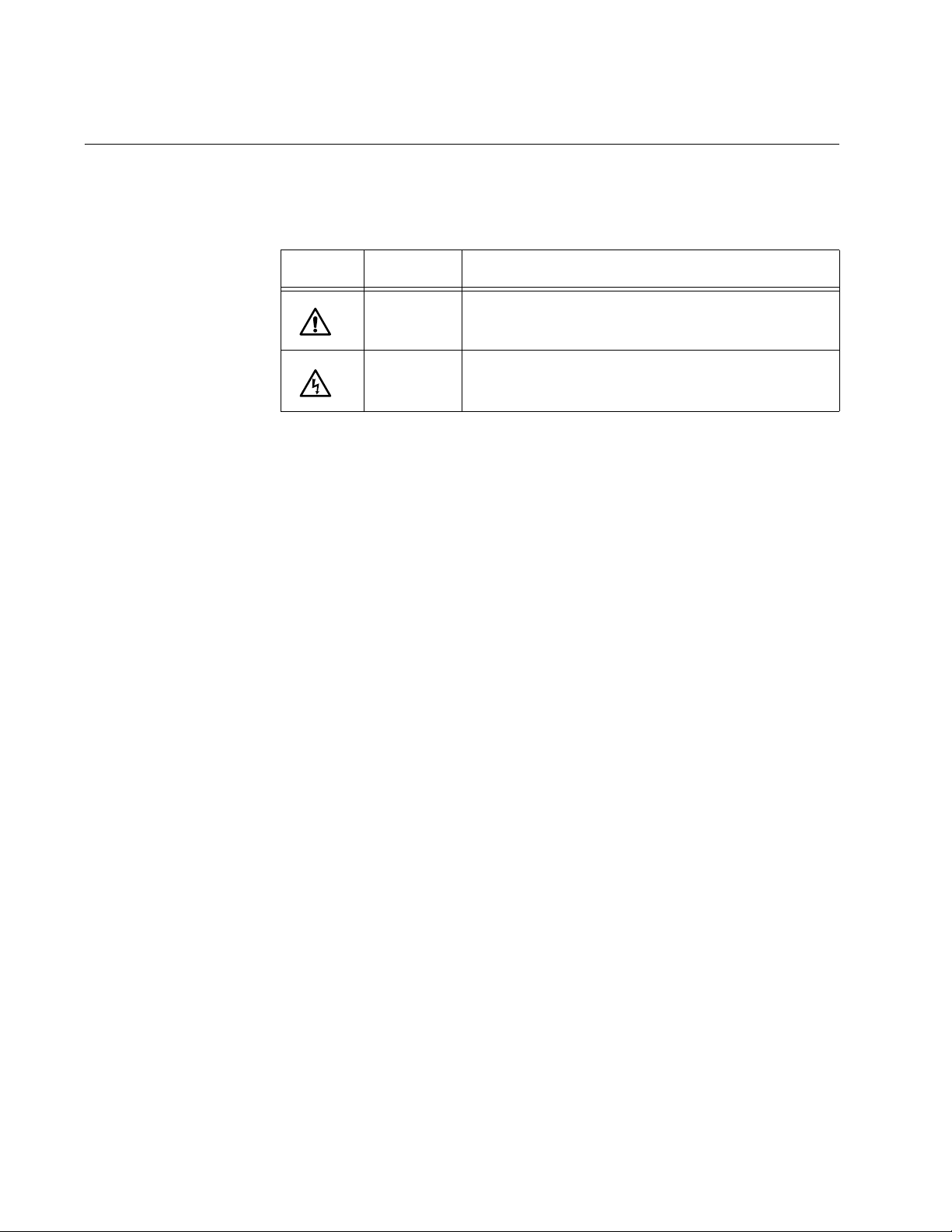
This document uses the safety symbols defined in Table 1.
Table 1. Safety Symbols
Symbol Meaning Description
Caution Performing or omitting a specific action may
result in equipment damage or loss of data.
Warning Performing or omitting a specific action may
result in electrical shock.
12
Page 13

Where to Find Web-based Guides
The installation and user guides for all Allied Telesis products are available
in portable document format (PDF) on our web site at
www.alliedtelesis.com. You can view the documents online or download
them onto a local workstation or server.
AT-MCR12 Media Conversion Rack-Mount Chassis Installation Guide
13
Page 14

Preface
Contacting Allied Telesis
This section provides Allied Telesis contact information for technical
support as well as sales and corporate information.
Online Support You can request technical support online by accessing the Allied Telesis
Knowledge Base: www.alliedtelesis.com/support/kb.aspx. You can use
the Knowledge Base to submit questions to our technical support staff and
review answers to previously asked questions.
Email and
Telephone
Support
For Technical Support via email or telephone, refer to the Support &
Services section of the Allied Telesis web site: www.alliedtelesis.com.
Select your country from the list displayed on the website. then select the
appropriate menu tab.
Warranty For hardware warranty information, refer to the Allied Telesis web site:
www.alliedtelesis.com/support/warranty.
Returning
Products
Sales or
Corporate
Products for return or repair must first be assigned a return materials
authorization (RMA) number. A product sent to Allied Telesis without an
RMA number will be returned to the sender at the sender’s expense.
To obtain an RMA number, contact the Allied Telesis Technical Support
group at our web site: www.alliedtelesis.com/support/rma. Select your
country from the list displayed on the website. Then select the appropriate
menu tab.
You can contact Allied Telesis for sales or corporate information through
our web site: www.alliedtelesis.com. To find the contact information for
your country, select Contact Us -> Worldwide Contacts.
Information
Management
Software Updates
14
New releases of management software for our managed products are
available from either of the following Internet sites:
Allied Telesis web site: www.alliedtelesis.com
Allied Telesis FTP server: ftp://ftp.alliedtelesis.com
If you prefer to download new software from the Allied Telesis FTP server
from your workstation’s command prompt, you will need FTP client
software and you must log in to the server. Enter “anonymous” for the user
name and your email address for the password.
Page 15

Chapter 1
Overview
This chapter provides information about the AT-MCR12 Media Conversion
Rack-Mount chassis and contains the following sections:
“Features” on page 16
“Power Status LEDs” on page 19
15
Page 16

Chapter 1: Overview
Features
The AT-MCR12 rack-mount chassis provides convenient rack-mount or
desktop installation for up to twelve Allied Telesis 10Base- and/or
100Base-T media converters. The chassis is available in both AC and DC
models.
Figure 1 shows a fully populated chassis with rack-mount brackets
attached. All products are connected to power through a factory-installed
power supply and power backplane.
LNK
REC
LNK
100Base-TX
REC
LNK
100Base-TX
REC
100Base-TX
LNK
REC
100Base-TX
LNK
REC
100Base-TX
LNK
REC
100Base-TX
LNK
REC
MCR12
LNK
REC
100Base-TX
MDI MDI-X
LNK
RECPWR
100Base-FX
TX RX
MC102 FAST ETHERNET MEDIA CONVERTER
LNK
REC
100Base-TX
MDI MDI-X
LNK
RECPWR
100Base-FX
TX RX
MC102 FAST ETHERNET MEDIA CONVERTER
LNK
REC
100Base-TX
MDI MDI-X
LNK
RECPWR
100Base-FX
TX RX
MC102 FAST ETHERNET MEDIA CONVERTER
LNK
REC
100Base-TX
MDI MDI-X
LNK
RECPWR
100Base-FX
TX RX
MC102 FAST ETHERNET MEDIA CONVERTER
LNK
REC
100Base-TX
MDI MDI-X
LNK
RECPWR
100Base-FX
TX RX
MC102 FAST ETHERNET MEDIA CONVERTER
100Base-TX
MDI MDI-X
LNK
RECPWR
100Base-FX
TX RX
MC102 FAST ETHERNET MEDIA CONVERTER
MDI MDI-X
LNK
RECPWR
100Base-FX
TX RX
MC102 FAST ETHERNET MEDIA CONVERTER
MDI MDI-X
LNK
RECPWR
100Base-FX
TX RX
MC102 FAST ETHERNET MEDIA CONVERTER
MDI MDI-X
LNK
MDI MDI-X
RECPWR
LNK
100Base-FX
RECPWR
100Base-FX
TX RX
TX RX
MC102 FAST ETHERNET MEDIA CONVERTER
MC102 FAST ETHERNET MEDIA CONVERTER
Power Supply LEDs
MDI MDI-X
LNK
RECPWR
100Base-FX
TX RX
MC102 FAST ETHERNET MEDIA CONVERTER
MDI MDI-X
LNK
RECPWR
100Base-FX
TX RX
MC102 FAST ETHERNET MEDIA CONVERTER
Front and Back
Panels
Figure 1. Full Populated AT-MCR12 Chassis with Rack Mount Brackets
Attached
Two LEDs on the front provide information about the status of the auxiliary
power supplies installed in the rear, as described in “Power Status LEDs”
on page 19.
Figure 2 shows the front panel of the AT-MCR12 chassis.
MEDIA CONVERTER RACKMOUNT CHASSIS
MCR12
PWR A
PWR B
16
Figure 2. AT-MCR12 Front Panel
Page 17

AT-MCR12 Media Conversion Rack-Mount Chassis Installation Guide
Figure 3 shows the back panels of the AC and DC versions of the chassis
as they are shipped with one power supply in slot A.
POWER
4
R
W
AC Model
P
M
O
eC
tr
n
e
C
Power Supply Slot A
Auxiliary Power Supply Slot B
1269
Auxiliary Power
Supply Slot
DC Model
1285
Power Supply Slot A
Auxiliary Power Supply Slot B
Figure 3. Back Panels
The AT-MCR12 chassis is shipped with one AT-PWR4 (AC) or AT-PWR9
(DC) power supply installed in slot A, with slot B for an auxiliary power
supply.
The power supply provides automatic load balancing for one or two power
supplies. If a power supply fails, the green power LED on the front of the
AT-MCR12 chassis goes out, and the entire power load is shifted to the
auxiliary power supply unit. The power supplies are hot-swappable.
For detailed information on the features and specifications of the
AT-PWR4 power supply, refer to the AT-PWR4 Power Supply Installation
Guide. Information about the features and specifications of the AT-PWR9
power supply is available in the AT-PWR9 Power Supply Installation
Guide.
Figure 4 shows the rear view of the AT-MCR12 rack-mount chassis with
17
Page 18

Chapter 1: Overview
two AT-PWR4 AC power supplies installed.
P
O
W
ER S
UPPLY
A
PO
WER
R
E
4
W
R
O
P
W
P
M
O
C
re
t
n
e
C
S
UP
PL
Y B
C
ent
r
eC
O
M
P
O
P
W
E
W
R
R
4
Figure 4. AT-MCR12 Chassis with Two AT-PWR4 AC Power Supplies
Installed
Figure 5 shows the rear view of the AT-MCR12 rack-mount chassis with
two AT-PWR9 DC power supplies installed.
P
OW
ER S
UPPLY
A
P
O
W
E
R
R
WE
PO
S
U
P
P
L
Y
P
O
W
E
R
1286
Figure 5. AT-MCR12 Chassis with Two AT-PWR9 DC Power Supplies
Installed
18
Page 19

Power Status LEDs
AT-MCR12 Media Conversion Rack-Mount Chassis Installation Guide
Table 1 describes the operation of the power status LEDs on the front of
the AT-MCR12 chassis.
Table 1. Power Status LEDs
PWR
LED
PWR A Green Power supply A is operating normally.
PWR B Green Power supply B is in operating normally.
Color Description
OFF Power supply A is off, not present, or has failed.
OFF Power supply B is off, not present, or has failed.
19
Page 20

Chapter 1: Overview
20
Page 21

Chapter 2
Installation
This chapter provides the installation instructions for the AT-MCR12
chassis and contains the following sections:
“Reviewing Safety Precautions” on page 22
“Verifying the Package Contents” on page 25
“Preparing the Site” on page 26
“Installing the Chassis on a Desktop” on page 27
“Installing the Chassis in a Rack” on page 28
“Grounding the Chassis” on page 30
“Installing a Media Converter in the Chassis” on page 32
“Installing an AT-CV1000 Chassis in an AT-MCR12 Rack-Mount
Chassis” on page 35
“Powering on an AC-Powered Chassis” on page 39
“Wiring and Powering on a DC-Powered Chassis” on page 40
“Installing an Auxiliary Power Supply” on page 43
“Warranty Registration” on page 44
21
Page 22

Chapter 2: Installation
Reviewing Safety Precautions
Please review the following safety precautions before you begin to install
the chassis or any of its components.
Note
The indicates that a translation of the safety statement is
available in a PDF document titled “Translated Safety Statements”
on the Allied Telesis website at www.alliedtelesis.com and on the
documentation CD shipped with this product.
Warning: Do not work on equipment or cables during periods of
lightning activity.
Warning: Power cord is used as a disconnection device. To deenergize equipment, disconnect the power cord.
E2
E3
Warning: Class I Equipment. This equipment must be earthed.
The power plug must be connected to a properly wired earth
ground socket outlet. An improperly wired socket outlet could
E4
E7
place hazardous voltages on accessible metal parts.
Pluggable Equipment. The socket outlet shall be installed near
E5
E6
the equipment and shall be easily accessible.
Caution: Air vents must not be blocked and must have free
access to the room ambient air for cooling.
Warning: Operating Temperature. This product is designed for a
maximum ambient temperature of 40° degrees C.
All Countries: Install product in accordance with local and
National Electrical Codes.
E8
22
Page 23

AT-MCR12 Media Conversion Rack-Mount Chassis Installation Guide
Warning: As a safety precaution, install a circuit breaker with a
minimum value of 15 Amps between the equipment and the DC
power source.
Always connect the wires to the LAN equipment first before you
connect the wires to the circuit breaker. Do not work with HOT
feeds to avoid the danger of physical injury from electrical shock.
Always be sure that the circuit breaker is in the OFF position
before connecting the wires to the breaker.
Warning: Do not strip more than the recommended amount of
wire. Stripping more than the recommended amount can create
a safety hazard by leaving exposed wire on the terminal block
after installation.
Warning: When installing this equipment, always ensure that the
frame ground connection is installed first and disconnected last.
E11
E10
E9
Warning: Check to see if there are any exposed copper strands
coming from the installed wire. When this installation is done
correctly there should be no exposed copper wire strands
extending from the terminal block. Any exposed wiring can
conduct harmful levels of electricity to persons touching the
wires.
This system works with positive grounded or negative grounded
DC systems.
Warning: Only trained and qualified personnel are allowed to
install or replace this equipment.
Warning: For centralized DC power connection, install only in a
restricted access area.
A tray cable is required to connect the power source if the unit is
powered by centralized DC power. The tray cable must be UL
listed Type TC tray cable and rated at 600 V and 90 degrees C,
with three conductors, minimum 14 AWG.
E12
E13
E23
E14
E24
Warning: Mounting of the equipment in the rack should be such
that a hazardous condition is not created due to uneven
mechanical loading.
E25
23
Page 24

Chapter 2: Installation
Warning: Remove all metal jewelry, such as rings and watches,
before installing or removing a line card from a powered-on
chassis.
E26
Warning: Circuit breaker is used as a disconnection device. To
de-energize equipment, shut down the circuit breaker and then
disconnect the input wire.
E38
Warning: DC input shall be from a secondary source isolated
from the mains by reinforced insulation.
24
Page 25

Verifying the Package Contents
Ensure that the following items are included in your package. If any item is
missing or damaged, contact your Allied Telesis sales representative for
assistance.
One AT-MCR12 Media Conversion Rack-Mount Chassis
Two rack-mount brackets
Six mounting screws
One power cord
One ground lug
Two M5 lock nuts
Documentation CD
Warranty card
AT-MCR12 Media Conversion Rack-Mount Chassis Installation Guide
25
Page 26

Chapter 2: Installation
Preparing the Site
Be sure to observe the following guidelines when planning the installation
of your chassis.
Make sure power for the chassis is accessible and cables can be
easily connected.
Cables must be away from sources of electrical noise such as radios,
transmitters, broadband amplifiers, power lines, fluorescent or halogen
light fixtures.
Air flow around the chassis and through its vents on the rear and side
panels should not be restricted.
If you are using the chassis on a desktop, make sure it is placed on a
level, secure surface.
Do not place objects on top of the chassis.
Do not expose the chassis to moisture or water.
Make sure the chassis is in a dust-free environment.
Use dedicated power circuits or power conditioners to supply reliable
electrical power to the network devices.
26
Page 27

Installing the Chassis on a Desktop
To install the chassis on a desktop, perform the following procedure:
1. Unpack all the items from the shipping container and store the
packaging material in a safe location.
Note
Keep the shipping material. You must use the original shipping
material if you need to return the chassis to Allied Telesis.
2. Place the chassis on a level, secure surface.
The chassis is equipped with four protective rubber feet. This allows
the chassis to be placed on many types of surfaces.
3. Do not apply power at this time. Go to “Grounding the Chassis” on
page 30.
AT-MCR12 Media Conversion Rack-Mount Chassis Installation Guide
27
Page 28

Chapter 2: Installation
Installing the Chassis in a Rack
To install the AT-MCR12 chassis in a rack, perform the following
procedure:
1. Place the chassis upside down on a level, secure surface.
2. Using a flat-head screwdriver, remove the rubber feet from the bottom
of the chassis and set them aside for future use.
3. Turn the chassis over.
4. Attach one rack-mount bracket to each side of the chassis with three
screws (provided) on each side, as shown in Figure 1
LNK
REC
100Base-TX
LNK
RECPWR
100Base-FX
TX RX
MCR12
LNK
REC
100Base-TX
MDI MDI-X
LNK
MDI MDI-X
RECPWR
100Base-FX
TX RX
MC102 FAST ETHERNET MEDIA CONVERTER
LNK
REC
100Base-TX
MDI MDI-X
LNK
RECPWR
100Base-FX
TX RX
MC102 FAST ETHERNET MEDIA CONVERTER
MC102 FAST ETHERNET MEDIA CONVERTER
LNK
REC
100Base-TX
MDI MDI-X
LNK
RECPWR
100Base-FX
TX RX
MC102 FAST ETHERNET MEDIA CONVERTER
LNK
REC
100Base-TX
MDI MDI-X
LNK
RECPWR
100Base-FX
TX RX
MC102 FAST ETHERNET MEDIA CONVERTER
LNK
REC
100Base-TX
MDI MDI-X
LNK
RECPWR
100Base-FX
TX RX
MC102 FAST ETHERNET MEDIA CONVERTER
LNK
REC
100Base-TX
MDI MDI-X
LNK
RECPWR
100Base-FX
TX RX
MC102 FAST ETHERNET MEDIA CONVERTER
LNK
REC
100Base-TX
MDI MDI-X
LNK
RECPWR
100Base-FX
TX RX
MC102 FAST ETHERNET MEDIA CONVERTER
LNK
REC
100Base-TX
MDI MDI-X
LNK
RECPWR
100Base-FX
TX RX
MC102 FAST ETHERNET MEDIA CONVERTER
LNK
REC
100Base-TX
MDI MDI-X
LNK
RECPWR
100Base-FX
TX RX
MC102 FAST ETHERNET MEDIA CONVERTER
LNK
REC
100Base-TX
MDI MDI-X
LNK
RECPWR
100Base-FX
TX RX
MC102 FAST ETHERNET MEDIA CONVERTER
LNK
REC
100Base-TX
MDI MDI-X
LNK
RECPWR
100Base-FX
TX RX
MC102 FAST ETHERNET MEDIA CONVERTER
Figure 1. Attaching the Rack-Mount Brackets
Warning
Mounting of the equipment in the rack should be such that a
hazardous condition is not created due to uneven mechanical
loading. E25
28
Page 29

AT-MCR12 Media Conversion Rack-Mount Chassis Installation Guide
5. Mount the chassis on the rack with two screws (not provided) on each
side, as illustrated in Figure 2.
MCR12
LNK
REC
100Base-TX
MDI MDI-X
LNK
RECPWR
100Base-FX
TX RX
MC102 FAST ETHERNET MEDIA CONVERTER
LNK
REC
100Base-TX
MDI MDI-X
LNK
RECPWR
100Base-FX
TX RX
MC102 FAST ETHERNET MEDIA CONVERTER
LNK
REC
100Base-TX
MDI MDI-X
LNK
RECPWR
100Base-FX
TX RX
MC102 FAST ETHERNET MEDIA CONVERTER
Figure 2. Installing the Chassis in a Rack
6. Do not apply power at this time. Go to “Grounding the Chassis” on
page 30.
29
Page 30

Chapter 2: Installation
Grounding the Chassis
Grounding the chassis requires the following items:
One ground lug (provided)
Two M5 lock nuts for securing the ground lug to the chassis (provided)
Crimping tool (not provided)
One 12 AWG stranded wire or 14 AWG solid wire (not provided)
To ground the chassis to a ground point, perform the following procedure:
1. Use a crimping tool to affix one end of the 12 AWG bundled or 14
AWG solid ground wire to the provided ground lug, as illustrated in
Figure 3.
Warning
To ensure a safe and proper operation, you must ground the chassis
to a ground point before powering on the chassis.
1270
Figure 3. Connecting the Wire to the Ground Lug
2. Place the ground lug on the two studs located on the rear panel of the
AT-MCR12 chassis, as shown in Figure 4.
Figure 4. Position of the Ground Lug on the Studs
30
Page 31

AT-MCR12 Media Conversion Rack-Mount Chassis Installation Guide
3. Secure the ground lug with the two M5 lock nuts provided, as
illustrated in Figure 5.
Figure 5. Securing the Ground Lug with Two M5 Lock Nuts
4. Attach the other end of the ground wire to an appropriate ground
(earth) rod of the building.
5. Go to “Powering on an AC-Powered Chassis” on page 39 to complete
the installation.
31
Page 32

Chapter 2: Installation
Installing a Media Converter in the Chassis
To install a media converter in the AT-MCR12 chassis, perform the
following procedure.
1. Select the slot where you want to install the media converter.
2. Loosen the captive screw that secures the mounting rail in the
AT-MCR12 chassis, and remove the mounting rail by sliding it out, as
shown in Figure 6.
MEDIA CONVERTER RACKMOUNT CHASSIS
MEDIA CONVERTER RACKMOUNT CHAASIS
MCR12
A
R
PW
B
R
PW
1251
Figure 6. Removing the Mounting Rail
Note
Leave the mounting rails in the slots until you are ready to install a
media converter.
32
Page 33

AT-MCR12 Media Conversion Rack-Mount Chassis Installation Guide
3. Position the media converter so that its top is facing up, align the
mounting rail with the left side of the media converter, and insert the
tabs on the mounting rail into the front and rear air vents on the media
converter as shown in Figure 7.
1000Base-T
PWR
LINK
CT
A
ML
ase
1000B
SML
MODE
LT
GIGABIT ETHERNET
B
MEDIA CONVERTER AUTO MDI/MDI-X
1
T
C
S
U
S
D
A
L
O
C
R
P
R
E
S
A
L
LINK
ACT
AT-MC1008/G
1049
Figure 7. Aligning and Connecting the Mounting Rail to the Media
Converter
4. While you hold the mounting rail onto the media converter, turn it over
so that the mounting rail is on the bottom and slide the assembly into
the chassis, as shown in Figure 8.
POWER
LNK
REC
100Base-TX
LNK
REC
100Base-TX
LNK
REC
100Base-TX
LNK
REC
100Base-TX
LNK
REC
100Base-TX
LNK
REC
100Base-TX
LNK
MCR12
NML
PWR
LNK
1000Base-SX
TX RX
LNK TST
LNK
NML
1000Base-LX
SINGLE MODE MULTI MODE
TX RX
CLASS 1
INTO BEAM
LASER LIGHT
DO NOT STARE
NML
PWR
LNK
1000Base-SX
TX RX
LNK TST
LNK
NML
1000Base-LX
SINGLE MODE MULTI MODE
TX RX
MC1001 GIGABIT ETHERNET MEDIA CONVERTER
MC1001 GIGABIT ETHERNET MEDIA CONVERTER
CLASS 1
INTO BEAM
LASER LIGHT
DO NOT STARE
NML
PWR
LNK
1000Base-SX
TX RX
LNK TST
LNK
NML
1000Base-LX
SINGLE MODE MULTI MODE
TX RX
CLASS 1
INTO BEAM
LASER LIGHT
DO NOT STARE
LNK
REC
100Base-TX
MDI MDI-X
LNK
RECPWR
100Base-FX
NML
PWR
LNK
1000Base-SX
TX RX
MC1001 GIGABIT ETHERNET MEDIA CONVERTER
TX RX
LNK TST
LNK
NML
1000Base-LX
SINGLE MODE MULTI MODE
TX RX
MC1001 GIGABIT ETHERNET MEDIA CONVERTER
CLASS 1
INTO BEAM
LASER LIGHT
DO NOT STARE
REC
100Base-TX
MDI MDI-X
100Base-FX
LNK
RECPWR
100Base-FX
TX RX
TX RX
MC102 FAST ETHERNET MEDIA CONVERTER
MC102 FAST ETHERNET MEDIA CONVERTER
LNK
RECPWR
MDI MDI-X
100Base-FX
LNK
RECPWR
TX RX
MC102 FAST ETHERNET MEDIA CONVERTER
MDI MDI-X
LNK
RECPWR
MDI MDI-X
100Base-FX
TX RX
MC102 FAST ETHERNET MEDIA CONVERTER
MC102 FAST ETHERNET MEDIA CONVERTER
MDI MDI-X
LNK
RECPWR
100Base-FX
TX RX
MC102 FAST ETHERNET MEDIA CONVERTER
1275
MDI MDI-X
LNK
RECPWR
100Base-FX
TX RX
MC102 FAST ETHERNET MEDIA CONVERTER
MDI MDI-X
LNK
RECPWR
100Base-FX
TX RX
MC102 FAST ETHERNET MEDIA CONVERTER
Figure 8. Installing the Media Converter with Mounting Rail in the Chassis
5. Gently press the media converter to seat the power connector into the
backplane.
33
Page 34

Chapter 2: Installation
6. Secure the mounting rail to the chassis by tightening the captive
screw, as shown in Figure 9.
LNK
REC
100Base-TX
LNK
REC
100Base-TX
LNK
REC
100Base-TX
LNK
REC
100Base-TX
LNK
REC
100Base-TX
LNK
REC
100Base-TX
LNK
1000Base-SX
TX RX
1000Base-LX
TX RX
CLASS 1
NML
PWR
LNK
LNK TST
LNK
NML
SINGLE MODE MULTI MODE
INTO BEAM
LASER LIGHT
DO NOT STARE
MCR12
NML
PWR
LNK
1000Base-SX
TX RX
LNK TST
LNK
NML
1000Base-LX
SINGLE MODE MULTI MODE
TX RX
MC1001 GIGABIT ETHERNET MEDIA CONVERTER
MC1001 GIGABIT ETHERNET MEDIA CONVERTER
CLASS 1
INTO BEAM
LASER LIGHT
DO NOT STARE
NML
PWR
LNK
1000Base-SX
TX RX
LNK TST
LNK
NML
1000Base-LX
SINGLE MODE MULTI MODE
TX RX
MC1001 GIGABIT ETHERNET MEDIA CONVERTER
CLASS 1
INTO BEAM
LASER LIGHT
DO NOT STARE
1000Base-SX
TX RX
1000Base-LX
TX RX
CLASS 1
NML
PWR
LNK
LNK TST
LNK
NML
SINGLE MODE MULTI MODE
INTO BEAM
LASER LIGHT
DO NOT STARE
REC
100Base-TX
MDI MDI-X
LNK
RECPWR
100Base-FX
TX RX
MC102 FAST ETHERNET MEDIA CONVERTER
MC1001 GIGABIT ETHERNET MEDIA CONVERTER
MDI MDI-X
LNK
RECPWR
100Base-FX
TX RX
MC102 FAST ETHERNET MEDIA CONVERTER
MDI MDI-X
LNK
RECPWR
100Base-FX
TX RX
MC102 FAST ETHERNET MEDIA CONVERTER
MDI MDI-X
LNK
RECPWR
100Base-FX
TX RX
MC102 FAST ETHERNET MEDIA CONVERTER
MDI MDI-X
LNK
RECPWR
100Base-FX
TX RX
MC102 FAST ETHERNET MEDIA CONVERTER
MDI MDI-X
LNK
RECPWR
100Base-FX
TX RX
MC102 FAST ETHERNET MEDIA CONVERTER
1277
MDI MDI-X
LNK
RECPWR
100Base-FX
TX RX
MC102 FAST ETHERNET MEDIA CONVERTER
Figure 9. Securing the Mounting Rail
POWER
LNK
REC
100Base-TX
MDI MDI-X
LNK
RECPWR
100Base-FX
TX RX
MC102 FAST ETHERNET MEDIA CONVERTER
34
Page 35

AT-MCR12 Media Conversion Rack-Mount Chassis Installation Guide
Installing an AT-CV1000 Chassis in an AT-MCR12 Rack-Mount Chassis
In order to install the AT-CV1000 chassis in an AT-MCR12 rack-mount
chassis, an AT-CVMCR Installation Adapter, as shown in Figure 10, is
required.
Note
For detailed descriptions and installation procedures for the
AT-MCR12 rack-mount chassis, refer to the AT-MCR12 Media
Conversion Rack-Mount Chassis Installation Guide available on the
Allied Telesis website, www.alliedtelesis.com.
Calculating the
Power
Requirements
293
Figure 10. AT-CVMCR Installation Adapter
Even if your AT-MCR12 rack-mount chassis contains two AT-PWR4
power supply modules (a primary and an auxiliary), the total available
power for the modules in the chassis is limited to 80 Watts. This limitation
determines how many media converters the AT-MCR12 chassis can
support before the primary power supply shuts down.
To avoid power problems, Allied Telesis strongly recommends that you
calculate the total power required to supply your chosen media converters
before you install them in the AT-MCR12 chassis. Use the following
approximate power consumption guidelines for your calculation:
Use 6 Watts of power for any MC series media converter and the
AT-CV1000 with any of the Converteon line cards except the
AT-CM2K0S.
Use 9 Watts of power for the AT-CV1000 with an AT-CM2K0S line
card installed.
If the total power requirement exceeds the 80 Watt limit, then multiple
AT-MCR12 rack-mount chassis are required.
Installing the
AT-CV1000
Chassis
To install an AT-CV1000 chassis in an AT-MCR12 rack-mount chassis
using the AT-CVMCR Installation Adapter, perform the following
procedure:
35
Page 36

Chapter 2: Installation
1. Choose the slot in the AT-MCR12 chassis where you want to install
the AT-CV1000 chassis and loosen the captive screw to remove the
mounting rail from that slot, as shown in Figure 11.
MEDIA CONVERTER RACKMOUNT CHASSIS
MEDIA CONVERTER RACKMOUNT CHAASIS
MCR12
A
R
PW
B
R
PW
1251
Figure 11. Removing the Mounting Rail from a Slot in the AT-MCR12
Chassis
2. Turn the AT-CV1000 chassis upside down.
3. Turn the AT-CVMCR adapter over, align it with the base of the
chassis, and attach it to the chassis with two screws (provided), as
shown in Figure 12.
T
C
U
1
D
S
O
S
R
A
P
L
C
R
E
S
A
L
1268
Figure 12. Installing the AT-CVMCR Adapter on the AT-CV1000 Chassis
36
Page 37

AT-MCR12 Media Conversion Rack-Mount Chassis Installation Guide
T
X
R
DY
LK
AT FD
SML
M
L
O
A
M
4. Turn the chassis over, as shown Figure 13.
Y
RD
1266
Figure 13. AT-CV1000 Chassis with AT-CVMCR Adapter Installed
5. Use the thumb tab on the adapter to slide the AT-CV1000 chassis into
the AT-MCR12 chassis, as shown in Figure 14.
MEDIA CONVERTER RACKMOUNT CHASSIS
NT CHAASIS
U
O
A
R
1252
PW
B
R
W
P
AT-CM202
F
X
LK
T
X
DY
R
SML
AT-CV1000
LK
AT FD
M
T
A
M
A
O
L
MCR12
IA CONVERTER RACKM
ED
M
Figure 14. Sliding the AT-CV1000 into the AT-MCR12 Chassis Slot
6. Press gently on the AT-CV1000 chassis to seat the chassis into the
backplane.
37
Page 38

Chapter 2: Installation
AT-C
V
1000
7. Tighten the captive screw on the AT-CVMCR adapter to secure the
AT-CV1000 in the chassis, as shown in Figure 15.
MEDIA CONVERTER RACKMOUNT CHASSIS
MEDIA CONVERTER RAC
MCR12
M
K
OUNT CHA
SIS
A
A
R
1253
PW
R B
PW
AT-CM202
F
X
DY
R
T
A
LK
AT FD
LK
T
X
M
A
O
L
M
SML
Figure 15. Tightening the Captive Screw on the AT-CVMCR Adapter
Install a line card in the according to the instructions in the AT-CV1000
One-Slot Chassis Installation Guide.
38
Page 39

Powering on an AC-Powered Chassis
To power on the chassis, perform the following procedure:
1. Connect the power cord to the power supply.
2. Plug the other end of the power cord into a wall outlet.
Warning: Power cord is used as a disconnection device. To deenergize equipment, disconnect the power cord. E3
Pluggable Equipment. The socket outlet shall be installed near
the equipment and shall be easily accessible. E5
3. Verify that the power on LED is illuminated and the power supply
cooling fan is operating normally.
AT-MCR12 Media Conversion Rack-Mount Chassis Installation Guide
39
Page 40

Chapter 2: Installation
Wiring and Powering on a DC-Powered Chassis
To wire and power on a DC-powered chassis, perform the following
procedure:
Warning: As a safety precaution, install a circuit breaker with a
minimum value of 15 Amps between the equipment and the DC
power source.
Always connect the wires to the LAN equipment first before you
connect the wires to the circuit breaker. Do not work with HOT
feeds to avoid the danger of physical injury from electrical shock.
Always be sure that the circuit breaker is in the OFF position
before connecting the wires to the breaker.
Warning: Only trained and qualified personnel are allowed to
install or replace this equipment.
E14
E9
1. Identify the negative, frame ground, and positive terminals on the
terminal block, as shown in Figure 16.
Positive
Ground
Figure 16. Locating the Terminals on the DC Terminal Block
2. Before you strip and attach the wires, review the following safety
precautions:
This system works with positive grounded or negative grounded
DC systems.
E13
Negative
40
Warning: For centralized DC power connection, install only in a
restricted access area.
E23
Page 41

AT-MCR12 Media Conversion Rack-Mount Chassis Installation Guide
A tray cable is required to connect the power source if the unit is
powered by centralized DC power. The tray cable must be UL
listed Type TC tray cable and rated at 600 V and 90 degrees C,
with three conductors, minimum 14 AWG.
E24
Warning: Circuit breaker is used as a disconnection device. To
de-energize equipment, shut down the circuit breaker and then
disconnect the input wire.
E38
Warning: DC input shall be from a secondary source isolated
from the mains by reinforced insulation.
3. With a 14-gauge wire-stripping tool, strip the three wires in the tray
cable coming from the DC input power source to 8 millimeters ± 1
millimeters (0.31 inches ± 0.039 inches), as shown in Figure 17.
8mm ±1mm
(0.31in. ±0.039in.)
Figure 17. Stripped Wire
Warning: Do not strip more than the recommended amount of
wire. Stripping more than the recommended amount can create
a safety hazard by leaving exposed wire on the terminal block
after installation.
E10
4. Connect the frame ground wire to the terminal marked with the ground
symbol by inserting the wire into the terminal block and tightening the
connection with a flathead screwdriver, as shown in Figure 18.
Warning: When installing this equipment, always ensure that the
frame ground connection is installed first and disconnected last.
E11
41
Page 42

Chapter 2: Installation
.
Figure 18. Connecting the Frame Ground Wire
5. Connect the positive feed wire to the terminal block marked +
(positive).
6. Connect the negative feed wire to the terminal block marked (negative).
Warning: Check to see if there are any exposed copper strands
coming from the installed wire. When this installation is done
correctly there should be no exposed copper wire strands
extending from the terminal block. Any exposed wiring can
conduct harmful levels of electricity to persons touching the
wires.
E12
7. Secure the tray cable near the rack framework using multiple cable
ties (not provided) to minimize the chance of the connections being
disturbed by casual contact with the wiring. Allied Telesis recommends
that you use at least four cable ties 10 centimeters (4 inches) apart
with the first one located within 15 centimeters (6 inches) of the
terminal block.
8. Ensure that the circuit breaker is in the Off position.
9. Connect the DC wires to the circuit breaker.
10. Power on the circuit breaker.
11. Verify that the Power LED is green. If it is not, refer to Chapter 3,
“Troubleshooting” on page 47.
42
Page 43

Installing an Auxiliary Power Supply
To install an auxiliary power supply unit in the power supply slot in the
back of the AT-MCR12 chassis, refer to the documentation that is shipped
with the power supply.
AT-MCR12 Media Conversion Rack-Mount Chassis Installation Guide
43
Page 44

Chapter 2: Installation
Warranty Registration
Allied Telesis hardware products are covered under limited warranties.
Some products have a longer warranty coverage than others.
The AT-MCR12 chassis has a limited warranty of Lifetime (24 months Fan
& PSU).
All Allied Telesis warranties are subject to the terms and conditions set out
on the Allied Telesis website at www.alliedtelesis.com/warranty.
44
Page 45

AT-MCR12 Media Conversion Rack-Mount Chassis Installation Guide
45
Page 46

Chapter 2: Installation
46
Page 47

Chapter 3
Troubleshooting
Follow the guidelines below to test and troubleshoot the installation of the
AT-MCR12 chassis in the event that a problem occurs.
Verify that the PWR A main power supply and PWR B optional power
supply LEDs are green. If one of the LEDs is OFF, do the following:
Check to be sure that the power supply is securely connected to the
power outlet.
Check to be sure that the power supply is securely seated in the
chassis.
For a DC unit, check to be sure that the wires are connected to the
correct terminals.
If AT-MCR12 chassis is not operating correctly after testing and
troubleshooting the installation, refer to “Contacting Allied Telesis” on
page 14 or visit our web site at www.alliedtelesis.com for support
information.
47
Page 48

Chapter 3: Troubleshooting
48
Page 49

Appendix A
Technical Specifications
Physical Specifications
Dimensions: W x H x D
483 mm x 132 mm x 226 mm
(19.0 in x 5.18 in x 8.88 in)
Environmental Specifications
Operating Temperature: 0° C to 40° C (32° F to 104° F)
Storage Temperature: -25° C to 70° C (-13° F to 158° F)
Operating Humidity: 5% to 90% non-condensing
Storage Humidity: 5% to 95% non-condensing
Operating Altitude: Up to 3,048 meters (10,000 feet)
Power Specifications
AT-PWR4 Power Supply: 100-120 VAC, 50/60 Hz, 3.0 A
Power Rating: 220-240 VAC, 50/60 Hz, 1.5 A
49
Page 50

Appendix A: Technical Specifications
Safety and Electromagnetic Emissions Certifications
EMI: FCC Class A, EN55022 Class A,
VCCI Class A, C-TICK, CE
Immunity: EN55024
Safety: UL60950-1 (
CULUS
), EN60950-1 (TUV),
CAN/CSA C22.2 No. 60950-1
Laser: EN60825
Quality and Reliability: MTBF > 100,000 hrs.
50
 Loading...