

Page 1

Media Converter
Chassis
AT-MCR1
Installation Guide
613-000687 Rev B
Page 2

Copyright © 2007 Allied Telesis, Inc.
All rights reserved. No part of this publication may be reproduced without
prior written permission from Allied Telesis, Inc.
Allied Telesis is a trademark of Allied Telesis, Inc. All other product names,
company names, logos or other designations mentioned herein are
trademarks or registered trademarks of their respective owners.
Allied Telesis, Inc. reserves the right to make changes in specifications and
other information contained in this document without prior written notice. The
information provided herein is subject to change without notice. In no event
shall Allied Telesis, Inc. be liable for any incidental, special, indirect, or
consequential damages whatsoever, including but not limited to lost profits,
arising out of or related to this manual or the information contained herein,
even if Allied Telesis, Inc. has been advised of, known, or should have
known, the possibility of such damages.
Page 3

Electrical Safety and Emission
Compliance Statement
Standards: This product meets the following standards.
U.S. Federal Communications Commission
Declaration of Conformity
Manufacturer Name: Allied Telesis, Inc.
Declares that the product: Media Converter Chassis
Model Numbers: AT-MCR1
This product complies with FCC Part 15B, Class B Limits:
This device complies with part 15 of the FCC Rules. Operation is subject
to the following two conditions: (1) This device must not cause harmful
interference, and (2) this device must accept any interference received,
including interference that may cause undesired operation.
Radiated Energy
Note: This equipment has been tested and found to comply with the limits
for a Class B digital device pursuant to Part 15 of FCC Rules. These limits
are designed to provide reasonable protection against harmful
interference in a residential installation. This equipment generates, uses
and can radiate radio frequency energy and, if not installed and used in
accordance with instructions, may cause harmful interference to radio or
television reception, which can be determined by turning the equipment
off and on. The user is encouraged to try to correct the interference by
one or more of the following measures:
- Reorient or relocate the receiving antenna.
- Increase the separation between the equipment and the receiver.
- Connect the equipment into an outlet on a circuit different from that to
which the receiver is connected.
- Consult the dealer or an experienced radio/TV technician for help.
Changes and modifications not expressly approved by the manufacturer
or registrant of this equipment can void your authority to operate this
equipment under Federal Communications Commission rules.
3
Page 4

Industry Canada
This Class B digital apparatus meets all requirements of the Canadian
Interference-Causing Equipment Regulations.
Cet appareil numérique de la classe B respecte toutes les exigences du
Règlement sur le matériel brouilleur du Canada.
RFI Emissions FCC Part 15 Class B
Immunity EN55024
Electrical Safety EN60950 (TUV),
UL 60950-1 (
CSA C22.2
cULus
),
Translated Safety Statements
Important: The indicates that a translation of the safety
statement is available in a PDF document titled “Translated Safety
Statements” posted on the Allied Telesis website at
www.alliedtelesis.com.
4
Page 5

Contents
Preface .........................................................................................7
Safety Symbols Used in this Document ........................................8
Where to Find Web-based Guides ................................................9
Contacting Allied Telesis .............................................................10
Online Support ....................................................................10
Email and Telephone Support.............................................10
Warranty..............................................................................10
Returning Products.............................................................. 10
Sales or Corporate Information ...........................................11
Chapter 1: Overview .................................................................13
Key Features ...............................................................................14
Status LEDs.................................................................................14
Chapter 2: Installation ..............................................................15
Reviewing Safety Precautions.....................................................16
Verifying the Package Contents ..................................................20
Selecting a Site............................................................................21
Installing a Media Converter in the Chassis ................................22
Installing the Chassis On a Table or Desktop (AC Models Only) 25
Installing the Chassis Under a Table (AC Models Only) .............26
Mounting the Chassis on the Wall ...............................................29
Installing the Chassis in a Rack................................................... 32
Powering On an AC-Powered Chassis........................................34
Wiring and Powering On a DC-Powered Chassis .......................37
Warranty Registration..................................................................42
Chapter 3: Troubleshooting ....................................................43
Appendix A: Technical Specifications ...................................45
Physical .......................................................................................45
5
Page 6

Contents
Temperature ................................................................................45
Electrical Rating (for AC version only).........................................45
Safety and Electromagnetic Emissions Certifications .................46
Compliance Standards ................................................................46
6
Page 7

Preface
This guide contains instructions on how to install an AT-MCR1
Media Converter Chassis.
This preface contains the following sections:
“Safety Symbols Used in this Document” on page 8
“Where to Find Web-based Guides” on page 9
“Contacting Allied Telesis” on page 10
7
Page 8
Preface
Safety Symbols Used in this Document
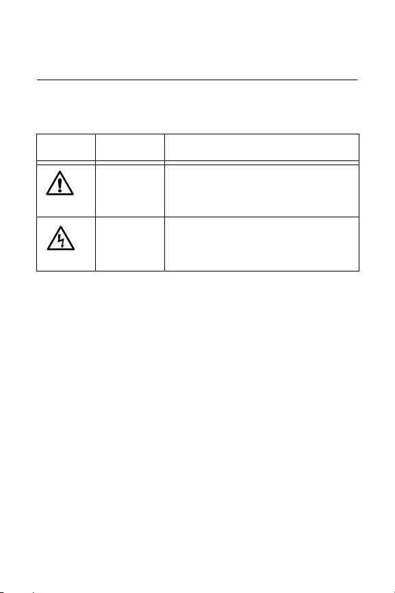
This document uses the safety symbols in Table 1.
Table 1. Safety Symbols
Symbol Meaning Description
Caution Performing or omitting a specific
action may result in equipment
damage or loss of data
Warning Performing or omitting a specific
action may result in electrical shock.
8
Page 9

AT-MCR1 Media Converter Chassis Installation Guide
Where to Find Web-based Guides
The installation and user guides for all Allied Telesis products are
available in portable document format (PDF) on our web site at
www.alliedtelesis.com. You can view the documents online or
download them onto a local workstation or server.
9
Page 10

Preface
Contacting Allied Telesis
This section provides Allied Telesis contact information for
technical support as well as sales or corporate information.
Online Support
You can request technical support online by accessing the Allied
Telesis Knowledge Base: www.alliedtelesis.com/kb. You can
use the Knowledge Base to submit questions to our technical
support staff and review answers to previously asked questions.
Email and Telephone Support
For technical support via email or telephone, refer to the Support &
Services section of the Allied Telesis web site:
www.alliedtelesis.com. Select your country from the list
displayed on the website, then select the appropriate menu tab.
Warranty
For hardware warranty information, refer to the Allied Telesis web
site: www.alliedtelesis.com/support/warranty. Select your
country from the list displayed on the website, then select the
appropriate menu tab.
Returning Products
Products for return or repair must first be assigned a return
materials authorization (RMA) number. A product sent to Allied
Telesis without an RMA number will be returned to the sender at
the sender’s expense.
To obtain an RMA number, contact Allied Telesis’ Technical
Support group through the Allied Telesis web site:
www.alliedtelesis.com/support/rma. Select your country from
the list displayed on the website, then select the appropriate menu
10
Page 11

AT-MCR1 Media Converter Chassis Installation Guide
tab.
Sales or Corporate Information
You can contact Allied Telesis for sales or corporate information
on our web site: www.alliedtelesis.com. To find the contact
information for your country, select Contact Us -> Worldwide
Contacts.
11
Page 12

Preface
12
Page 13
Chapter 1
Overview
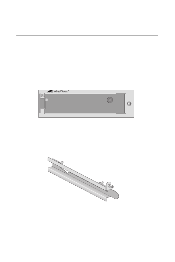
The AT-MCR1, shown in Figure 1, is a chassis with an internal
power supply designed to house one Allied Telesis media
converter. The AT-MCR1 chassis provides convenient installation
options: on a desktop, mounted under a table, placed on the wall,
or installed in an industry standard 19” or 23” rack.
AT-MCR1
PWR
1046
Figure 1. AT-MCR1 Media Converter Chassis
The AT-MCR1 chassis includes a mounting rail (750-10857-00),
as shown in Figure 2, for installing a media converter.
Figure 2. Mounting Rail
1047
13
Page 14

Chapter 1: Overview
Key Features
The AT-MCR1 chassis has the following features:
LED for unit status
One slot for an ATI standard media converter
Internal AC/DC power supply
Desktop, wall, under table, or rack mount installation
Status LEDs
Refer to Table 2 for a description of the chassis LED.
Table 2. LED
LEDs Color Description
PWR Green Power on the AT-MCR1 chassis
is ON.
OFF Power on AT-MCR1 chassis is
14
OFF.
Page 15

Chapter 2
Installation
This chapter contains the following sections:
“Reviewing Safety Precautions” on page 16
“Verifying the Package Contents” on page 20
“Selecting a Site” on page 21
“Installing a Media Converter in the Chassis” on page 22
“Installing the Chassis On a Table or Desktop (AC Models
Only)” on page 25
“Installing the Chassis Under a Table (AC Models Only)” on
page 26
“Mounting the Chassis on the Wall” on page 29
“Installing the Chassis in a Rack” on page 32
“Powering On an AC-Powered Chassis” on page 34
“Wiring and Powering On a DC-Powered Chassis” on page 37
“Warranty Registration” on page 42
15
Page 16

Chapter 2: Installation
Reviewing Safety Precautions
Review the following safety precautions before you begin to install
the AT-MCR1 chassis.
Note
The indicates that a translation of the safety statement is
available in a PDF document titled “Translated Safety
Statements” on the Allied Telesis website at
www.alliedtelesis.com.
Warning: Class 1 Laser product.
Warning: Do not work on equipment or cables during
periods of lightning activity.
Warning: Power cord is used as a disconnection
device. To de-energize equipment, disconnect the
power cord.
Warning: Class I Equipment. This equipment must be
earthed. The power plug must be connected to a
properly wired earth ground socket outlet. An
improperly wired socket outlet could place hazardous
voltages on accessible metal parts.
Pluggable Equipment. The socket outlet shall be
installed near the equipment and shall be easily
accessible.
16
E3
E5
E2
L 1
E4
Page 17

AT-MCR1 Media Converter Chassis Installation Guide
Caution: Air vents must not be blocked and must have
free access to the room ambient air for cooling.
Warning: Operating Temperature. This product is
designed for a maximum ambient temperature of 40°
degrees C.
All Countries: Install product in accordance with local
and National Electrical Codes.
Warning: As a safety precaution, install a circuit
breaker with a minimum value of 16 Amps between the
equipment and the DC power source.
Always connect the wires to the LAN equipment first
before you connect the wires to the circuit breaker. Do
not work on HOT feeds to avoid the danger of physical
injury from electrical shock. Always be sure that the
circuit breaker is in the OFF position before connecting
the wires to the breaker.
Warning: Do not strip more than the recommended
amount of wire. Stripping more than the recommended
amount can create a safety hazard by leaving exposed
wire on the terminal block after installation.
E7
E9
E8
E10
E6
Warning: When installing this equipment, always
ensure that the power supply ground connection is
installed first and disconnected last.
E11
17
Page 18

Chapter 2: Installation
Warning: Check to see if there are any exposed copper
strands coming from the installed wires. When this
installation is done correctly there should be no
exposed copper wire strands extending from the
terminal block. Any exposed wiring can conduct harmful
levels of electricity to persons touching the wires.
E12
This system will work with a positive grounded or
negative grounded DC system.
Warning: Only trained and qualified personnel are
allowed to install or to replace this equipment.
Caution: The attached mounting brackets must be
used to securely mount the device on the wall.
Warning: For centralized DC power connection, install
only in a restricted access area.
A tray cable is required to connect the power source if
the chassis is powered by centralized DC power. The
tray cable must be an UL listed Type TC tray cable and
rated at 600 V and 90 degree C, with three conductors,
minimum 14 AWG.
E24
E13
E23
E14
E15
Caution: Installation of the equipment in a rack should
be such that the amount of air flow required for safe
operation of the equipment is not compromised.
18
E36
Page 19

AT-MCR1 Media Converter Chassis Installation Guide
Warning: Reliable earthing of rack-mounted equipment
should be maintained. Particular attention should be
given to supply connections other than direct
connections to the branch circuits (e.g., use of power
strips).
E37
19
Page 20

Chapter 2: Installation
Verifying the Package Contents
Make sure the following items are included in your package. If any
item is missing or damaged, contact your Allied Telesis sales
representative for assistance.
One AT-MCR1 Media Converter Chassis with a mounting
rail installed
Four protective rubber feet (for desktop use only)
Two mounting brackets
Eight bracket-mounting screws (M3X6)
Four wall-mount plastic anchors (No. 6-10, 7/8 inch)
Four self-tapping screws (3.5mm X 20mm)
One retaining clip (AC model only)
This installation guide
Warranty card
Items needed for installation but not provided by Allied Telesis:
Phillips screw driver
Mounting screws for under-table installation
20
Page 21

AT-MCR1 Media Converter Chassis Installation Guide
Selecting a Site
Be sure to observe the following requirements when choosing a
site for your chassis.
Make sure you are placing the chassis in a dust-free and
moisture-free environment.
Do not block the ventilation openings on the unit. Allow at
least 10 centimeters (4 inches) of space at the front and back
of the unit for ventilation.
Make sure that the chassis’ power is accessible and cables
can be connected easily.
Cabling should be away from sources of electrical noise such
as radios, transmitters, broadband amplifiers, power lines,
and fluorescent fixtures.
Do not place objects on top of the chassis.
Use dedicated power circuits or power conditioners to supply
power to the chassis.
21
Page 22

Chapter 2: Installation
Installing a Media Converter in the Chassis
To install a media converter in the AT-MCR1 chassis, perform the
following procedure:
1. Remove all components from the shipping packages.
Note
Store the packaging material in a safe place. You must use
the original shipping material if you need to return the unit to
Allied Telesis.
2. Loosen the captive screw on the mounting rail and remove it
from the chassis, as shown in Figure 3.
AT-MCR1
R
W
P
1048
Figure 3. Removing the Mounting Rail from the Chassis
22
Page 23

AT-MCR1 Media Converter Chassis Installation Guide
1
0
0
0
B
a
s
e
AT-MC1008/GB
G
IG
A
B
I
T
E
T
H
E
R
N
E
T
M
EDIA
C
O
N
V
E
RT
ER
AUTO
MD
I/M
D
I-
X
1
0
0
0
B
a
s
e
-T
P
W
R
L
IN
K
ACT
ML
SML
L
T
M
O
D
E
L
IN
K
ACT
C
L
A
S
S
1
L
A
S
E
R
P
R
O
D
U
C
T
1050
3. Align the mounting rail with the media converter, placing the
two pins into the front and rear air vents, as shown in Figure
4.
T
-
e
s
a
B
0
0
0
1
R
W
P
K
IN
L
CT
A
X
I-
D
e
s
ML
a
B
I/M
D
M
SML
E
D
O
LT
AUTO
R
E
RT
E
V
N
O
C
1
T
C
S
U
S
D
A
L
O
C
R
P
R
E
K
S
A
L
IN
L
ACT
AT-MC1008/GB
1049
0
0
0
1
M
IA
D
E
M
T
E
N
R
E
H
T
E
IT
B
A
IG
G
Figure 4. Aligning the Mounting Rail with the Media Converter
4. While you hold the mounting rail against the media converter,
slide the two together into the chassis slot, as shown in
Figure 5.
R
W
P
1050
Figure 5. Sliding the Media Converter into the Chassis Slot
23
Page 24

Chapter 2: Installation
1
0
0
0
B
a
s
e
AT-MC1008/GB
G
IG
A
B
IT E
T
H
E
R
N
E
T
M
E
D
IA
C
O
N
V
E
RT
E
R
A
U
TO
MD
I/M
D
I-
X
1
0
0
0
B
a
s
e
-T
P
W
R
L
IN
K
ACT
ML
SML
LT
M
O
D
E
L
INK
ACT
C
L
A
S
S
1
L
A
S
E
R
P
R
O
D
U
C
T
5. Press gently on the media converter to seat the power plug
into the chassis.
6. Tighten the captive screw on the mounting rail to secure the
media converter in the chassis, as shown in Figure 6
AT-MCR1
R
W
P
1278
Figure 6. Tightening the Captive Screw on the Mounting Rail
24
Page 25

AT-MCR1 Media Converter Chassis Installation Guide
Installing the Chassis On a Table or Desktop (AC Models Only)
To install the chassis on a table or desktop, perform the following
procedure:
1. Turn the AT-MCR1 chassis over.
2. Attach the four protective rubber feet to the bottom of the
chassis, as shown in Figure 7.
AT-MC100
8/GB
G
IG
A
B
IT E
TH
E
R
N
E
T
M
E
D
IA
C
O
N
V
RTER
E
AUTO M
D
I/M
D
I-
X
ACT
L
T
LINK
SM
PWR
L
M
O
D
E
M
L
PWR
1000Ba
se-T
AT-MCR 1
1000Ba
se
Figure 7. Attaching the Rubber Feet
3. Turn the chassis over and place it on a flat and secure
surface, leaving ample space around the chassis for
ventilation.
The chassis is ready for cabling and powering up.
For cabling instructions, refer to the installation guide that
comes with the Allied Telesis media converter.
For powering up instructions, refer to “Powering On an AC-
Powered Chassis” on page 34.
ACT
LINK
LASER PRODUC
T
CLAS
S 1
1051
25
Page 26

Chapter 2: Installation
Installing the Chassis Under a Table (AC Models Only)
The AT-MCR1 chassis can be mounted under a table using the
mounting brackets shipped with the chassis.
Note
Make sure that the under-table location provides easy access
for installing the twisted pair, fiber optic, and power cables to
and from the chassis.
Note
Before you install the AT-MCR1 chassis under a table, install
the cables. For cabling instructions, refer to the installation
guide that is shipped with the Allied Telesis media converter.
To install an AT-MCR1 chassis under a table, perform the
following procedure:
1. If attached, remove the rubber feet and power cord from the
chassis.
2. Select a location under a table and mark two hole locations
for the mounting screws.
Caution
The mounting brackets provided in the chassis package must
be used to securely install the chassis under the table.
26
Page 27

AT-MCR1 Media Converter Chassis Installation Guide
1
0
0
0
B
a
s
e
AT-M
C10
08/G
B
GIGABIT ETHERNET MEDIA CONVERTER AUT
O MDI/MDI-X
1
0
0
0
B
a
s
e
-T
P
W
R
L
I
N
K
ACT
M
L
S
M
L
LT
MODE
L
IN
K
ACT
CLASS
1
LASE
R P
R
ODUCT
1000B
ase
AT-MC1008/GB
G
IG
A
B
IT
E
T
H
E
R
N
E
T
M
E
D
IA
C
O
N
V
ER
T
E
R
AUTO
MD
I/M
D
I-
X
100
0B
ase-T
PWR
LINK
ACT
M
L
S
M
L
LT
M
O
D
E
LINK
A
CT
C
L
A
S
S
1
L
A
S
E
R
P
R
O
D
U
C
T
3. Attach one mounting bracket (provided) to each side of the
chassis using the bracket mounting screws (provided), as
shown in Figure 8.
AT-MCR1
R
W
P
1052
Figure 8. Attaching Brackets for Under-Table Installation
4. Position and mount the top of the chassis under the table
using the mounting screws (not provided), as shown in Figure
9.
1
R
C
-M
T
A
PWR
1053
Figure 9. Mounting the Chassis under the Table
27
Page 28

Chapter 2: Installation
5. Make sure that the chassis is securely mounted under the
table.
6. Power the chassis on following the instructions in “Powering
On an AC-Powered Chassis” on page 34.
28
Page 29

AT-MCR1 Media Converter Chassis Installation Guide
Mounting the Chassis on the Wall
The chassis can be mounted vertically on a wall using the
mounting brackets that come with the unit.
To mount an AT-MCR1 chassis on the wall, perform the following
procedure:
1. If attached, remove the rubber feet and power cord from the
chassis.
2. Select a wall location for the chassis and mark two hole
locations for the wall-mounting screws or plastic wall anchors
(for wall-mounting onto a concrete wall).
Note
Make sure that the location provides easy access for
installing the twisted pair, fiber optic, and power cables to and
from the chassis.
Note
If the AT-MCR1 is to be mounted onto a concrete wall, make
sure to drill the required holes with the drill bit using the drill
bit size that is suitable for the plastic wall anchors. Then,
insert the plastic wall anchors.
Caution
The attached mounting brackets must be used to securely
mount the chassis onto the wall.
29
Page 30

Chapter 2: Installation
1
0
0
0
B
a
s
e
AT-M
C10
08/G
B
GIGABIT ETHERNET MEDIA CONVERTER AUT
O MDI/MDI-X
1
0
0
0
B
a
s
e
-
T
P
W
R
L
IN
K
ACT
M
L
S
M
L
LT
MODE
L
IN
K
ACT
CLASS 1
LASE
R P
ROD
UCT
3. Turn the chassis over and attach a mounting bracket
(provided) to each side of the chassis using the bracket
mounting screws (provided), as shown in Figure 10.
AT-MCR1
R
W
P
1052
Figure 10. Attaching the Brackets for Wall Mounting
4. Position and mount the chassis on the wall using the
mounting screws, as shown in Figure 11.
AT-MC1008/GB
ACT
L
A
S
E
R
C
LINK
P
L
R
A
S
O
S
D
U
1
C
T
G
IG
A
B
IT
E
T
H
E
R
N
E
T
M
E
D
IA
C
O
N
V
E
RT
E
M
R
O
1000Ba
D
E
LT
se
SM
L
M
L
AUTO
M
D
I
/M
D
ACT
I-X
LINK
PWR
1000Ba
se-T
AT-MCR1
P
W
R
30
1054
Figure 11. Mounting the Chassis on the Wall
Page 31

AT-MCR1 Media Converter Chassis Installation Guide
5. Make sure that the chassis is securely mounted onto the wall.
6. Install the cables.
For cabling instructions, refer to the installation guide that is
shipped with the Allied Telesis media converter.
7. Power on the chassis, referring to one of the following
sections:
“Powering On an AC-Powered Chassis” on page 34
“Wiring and Powering On a DC-Powered Chassis” on
page 37
31
Page 32

Chapter 2: Installation
Installing the Chassis in a Rack
You can mount the chassis in an industry-standard 19” or 23” rack.
To install the chassis in a rack, perform the following procedure:
1. If attached, remove the rubber feet, data cables, and power
cord from the chassis.
2. Attach one mounting bracket (provided) to the right side of
the AT-MCR1 chassis using the bracket mounting screws
(provided), as shown in Figure 12.
C
L
L
A
A
S
S
E
S
R
1
P
R
O
D
U
C
T
LIN
K
ACT
AT-MC1
1
0
0
0
B
a
008/GB
s
e
M
O
D
G
E
IG
A
B
M
IT E
L
T
Figure 12. Attaching Bracket for Rack Mounting
AT-MC
H
SM
E
R
L
N
E
T
M
R1
1
0
LT
0
0
B
E
a
D
s
e
IA
T
C
O
N
PWR
V
E
RT
ER
LINK
AC
T
P
W
R
AUTO
M
D
I
/M
D
IX
1055
Note
Make sure that the location provides easy access for
installing the twisted pair, fiber optic, and power cables to and
from the chassis.
32
Page 33

AT-MCR1 Media Converter Chassis Installation Guide
3. Mount the AT-MCR1 chassis on a 19” or 23” rack using the
rackmounting screws (not provided), as shown in Figure 13.
C
L
L
A
A
S
S
E
S
R
1
P
R
O
D
U
C
T
LIN
K
ACT
AT-MC1
1
0
0
0
B
a
008/GB
s
e
M
O
D
G
E
IG
A
B
M
IT E
L
T
AT-MC
H
S
E
M
R
L
N
E
T
M
R1
1
0
LT
0
0
B
E
a
D
s
e
IA
T
C
O
N
PWR
V
E
RT
ER
LINK
AC
T
P
W
R
AUTO
M
D
I
/M
D
I-
X
1056
Figure 13. Mounting the Chassis in a Rack
4. Make sure that the chassis is securely mounted in the rack.
5. Install the cables.
For cabling instructions, refer to the installation guide that is
shipped with the Allied Telesis media converter.
6. Power on the chassis, referring to one of the following
sections:
“Powering On an AC-Powered Chassis” on page 34
“Wiring and Powering On a DC-Powered Chassis” on
page 37
33
Page 34

Chapter 2: Installation
Powering On an AC-Powered Chassis
To apply power to an AC-powered AT-MCR1 chassis, perform the
following procedure:
1. Install the retaining clip on the chassis, as shown in
Figure 14.
100-240VAC ~
1022
Figure 14. Installing the Power Cord Retaining Clip
2. Position the power cord retaining clip in the up position, as
shown in Figure 15.
100-240VAC ~
1023
Figure 15. Power Cord Retaining Clip in the Up Position
34
Page 35

AT-MCR1 Media Converter Chassis Installation Guide
3. Plug the power cord into the power connector on the back of
the chassis, as shown in Figure 16.
100-240VAC ~
1057
Figure 16. Plugging the Power Cord into the Chassis
4. Secure the cord by lowering the power cord retaining clip, as
shown in Figure 17.
100-240VAC ~
1024
Figure 17. Securing the Power Cord with the Retaining Clip
5. Plug the other end of the power cord into a wall outlet.
Warning: Power cord is used as a disconnection
device. To de-energize equipment, disconnect the
power cord.
E3
35
Page 36

Chapter 2: Installation
Pluggable Equipment. The socket outlet shall be
installed near the equipment and shall be easily
accessible.
E5
6. Verify that the PWR LED in the front of the chassis is green.
If the PWR LED is OFF, refer to Chapter 3, ”Troubleshooting”
on page 43 for instructions.
The chassis runs a series of self-diagnostic tests, which take
a few seconds to perform. After the self tests are complete,
the chassis is ready for normal network operations.
For cabling instructions, refer to the installation guide that is
shipped with the Allied Telesis media converter.
36
Page 37

AT-MCR1 Media Converter Chassis Installation Guide
Wiring and Powering On a DC-Powered Chassis
To wire and power on a DC-powered chassis, perform the
following procedure:
Warning
As a safety precaution, install a circuit breaker with a
minimum value of 15 Amps between the equipment and the
DC power source.
Always connect the wiring to the LAN equipment first before
you connect the wiring to the circuit breaker. Do not work with
HOT feeds to avoid the danger of physical injury from
electrical shock. Always be sure that the breaker is in the
OFF position before connecting the wires to the breaker.
E9
Warning
The DC input shall be from a secondary source isolated from
the mains by reinforced insulation.
Warning: Only trained and qualified personnel are allowed to
install or to replace this equipment. E14
Warning: For centralized DC power connection, install only in
a restricted access area. E23
37
Page 38

Chapter 2: Installation
A tray cable is required to connect the power source if the
chassis is powered by centralized DC power. The tray cable
must be an UL listed Type TC tray cable and rated at 600 V
and 90 degree C, with three conductors, minimum 14 AWG.
E24
1. On the back panel of the chassis is a DC terminal block,
starting from the left side of the terminal block, identify the
positive, frame ground, and negative terminals, using the
symbols above the terminal block, as shown in Figure 18.
40-60VDC
1058
Positive
Ground
Figure 18. DC Terminal Block
2. With a 14-gauge wire-stripping tool, strip the three wires in
the tray cable coming from the DC input power source to
8mm ± 1mm (0.31 in., ± 0.039 in.), as shown in Figure 19.
Negative
8mm ±1mm
(0.31in. ±0.039in.)
Figure 19. Stripped Wire
38
Page 39

AT-MCR1 Media Converter Chassis Installation Guide
40-60VDC
Warning
Do not strip more than the recommended amount of wire.
Stripping more than the recommended amount can create a
safety hazard by leaving exposed wire on the terminal block
after installation. E10
3. Connect the frame ground wire to the terminal marked with
the ground symbol by inserting the wire into the terminal and
tightening the connection with a flathead screwdriver, as
shown in Figure 20 on page 39.
Warning
When installing this equipment, always ensure that the power
supply ground connection is installed first and disconnected
last. E11
40-60VDC
1059
Figure 20. Inserting Wires into a DC Terminal Block
4. Connect the positive feed wire to the terminal block marked
(+).
39
Page 40

Chapter 2: Installation
5. Connect the negative feed wire to the terminal block marked
(-).
Warning
Check to see if there are any exposed copper strands coming
from the installed wires. When this installation is done
correctly there should be no exposed copper wire strands
extending from the terminal block. Any exposed wiring can
conduct harmful levels of electricity to persons touching the
wires. E12
6. Secure the tray supply cable near the rack framework using
multiple cable ties to minimize the chance of the connections
being disturbed by casual contact with the wiring. Use at least
four cable ties, separated four inches apart. Locate the first
one within six inches of the terminal block.
This system will work with a positive grounded or negative
grounded DC system. E13
7. Ensure that the circuit breaker is in the OFF position.
8. Connect the DC wires to the circuit breaker.
9. Power on the circuit breaker.
10. Verify that PWR LED in the front of the chassis green.
If the PWR LED is OFF, refer to Chapter 3, ”Troubleshooting”
on page 43 for instructions.
The chassis runs a series of self-diagnostic tests, which take
a few seconds to perform. Once the self tests are complete,
the chassis is ready for normal network operations.
40
Page 41

AT-MCR1 Media Converter Chassis Installation Guide
For cabling instructions, refer to the installation guide that is
shipped with the Allied Telesis media converter.
41
Page 42

Chapter 2: Installation
Warranty Registration
When you have finished installing the product, register your
product by completing the enclosed warranty card and sending it
in. You can also fill out the registration online by selecting
“Warranties” under “Support & Services” from
www.alliedtelesis.com.
42
Page 43

Chapter 3
Trouble sho oti ng
Follow the guidelines below to test and troubleshoot the
installation in the event a problem occurs.
If the PWR LED is OFF, do the following:
Check to be sure that the power adapter is securely connected
to the power source and to the DC connector on the front of
the AT-MCR1 chassis.
Check to be sure that the power outlet has power by
connecting another device to it.
Try replacing the power adapter with another power adapter.
If there is a communication problem between the end-nodes
connected to the chassis, do the following:
Verify that the chassis and end-nodes are operating with the
same duplex mode.
If you are still experiencing problems after testing and
troubleshooting the installation, refer to “Contacting Allied Telesis”
on page 10. For support information, visit our web site at
www.alliedtelesis.com.
43
Page 44

Chapter 3: Troubleshooting
44
Page 45

Appendix A
Technical Specifications
Physical
Dimensions: W x D x H
130 mm x 166 mm x 44 mm
(5.118 in x 6.535 in x 1.732 in)
Weight: .27 kg (0.60 lbs)
Temperature
Operating Temperature: 0° C to 40° C
Storage Temperature: -25° C to 70° C
Operating Humidity: 5% to 90% non-condensing
Storage Humidity: 5% to 95% non-condensing
Operating Altitude: Up to 3,048 meters
Electrical Rating (for AC version only)
Input Supply Voltage: 100~240 VAC
Output Current: 1A (maximum)
Power Consumption: 8 Watts (maximum)
(32° F to 104° F)
(-13° F to 158° F)
(10,000 feet)
45
Page 46

Appendix A: Technical Specifications
Safety and Electromagnetic Emissions Certifications
RFI Emissions FCC Part 15 Class B
Immunity EN55024
Electrical Safety EN60950 (TUV), CE
Compliance Standards
RoHS Compliant
46
 Loading...