

Page 1

Fast Ethernet
Media Converters
AT-MCF2012LC
AT-MCF2012LC/1
Installation Guide
613-000574 Rev. A
Page 2

Copyright © 2006 Allied Telesis, Inc.
All rights reserved. No part of this publication may be reproduced without prior written
permission from Allied Telesis, Inc.
Microsoft and Internet Explorer are registered trademarks of Microsoft Corporation.
Netscape Navigator is a registered trademark of Netscape Communications Corporation. All
other product names, company names, logos or other designations mentioned herein are
trademarks or registered trademarks of their respective owners.
Allied Telesis, Inc. reserves the right to make changes in specifications and other
information contained in this document without prior written notice. The information provided
herein is subject to change without notice. In no event shall Allied Telesis, Inc. be liable for
any incidental, special, indirect, or consequential damages whatsoever, including but not
limited to lost profits, arising out of or related to this manual or the information contained
herein, even if Allied Telesis, Inc. has been advised of, known, or should have known, the
possibility of such damages.
Page 3

Electrical Safety and Emissions Standards
This product meets the following standards.
U.S. Federal Communications Commission
Radiated Energy
Note: This equipment has been tested and found to comply with the limits for a
Class A digital device pursuant to Part 15 of FCC Rules. These limits are
designed to provide reasonable protection against harmful interference when
the equipment is operated in a commercial environment. This equipment
generates, uses, and can radiate radio frequency energy and, if not installed
and used in accordance with this instruction manual, may cause harmful
interference to radio communications. Operation of this equipment in a
residential area is likely to cause harmful interference in which case the user
will be required to correct the interference at his own expense.
Note: Modifications or changes not expressly approved of by the manufacturer
or the FCC, can void your right to operate this equipment.
Industry Canada
This Class A digital apparatus complies with Canadian ICES-003.
Cet appareil numérique de la classe A est conforme à la norme NMB-003 du
Canada.
RFI Emissions FCC Class A, EN55022 Class A,
EN61000-3-2, EN61000-3-3, VCCI Class A,
C-TICK, CE
Warning: In a domestic environment this product may cause radio
interference in which case the user may be required to take adequate
measures.
EMC (Immunity) EN55024
Electrical Safety EN60950-1 (TUV), UL 60950-1 (
Laser Safety EN60825
CULUS
)
3
Page 4

Translated Safety Statements
Important: The indicates that a translation of the safety statement is available in a PDF
document titled “Translated Safety Statements” (613-000405) posted on the
Allied Telesis website at www.alliedtelesis.com.
4
Page 5

Contents
Preface .............................................................................................................. 11
Safety Symbols Used in this Document .............................................................. 12
Where to Find Web-based Guides...................................................................... 13
Contacting Allied Telesis ..................................................................................... 14
Online Support ............................................................................................. 14
Email and Telephone Support...................................................................... 14
Warranty Registration .................................................................................. 14
Returning Products ...................................................................................... 14
Sales or Corporate Information .................................................................... 14
Management Software Updates................................................................... 14
Chapter 1: Overview ......................................................................................... 15
Features .............................................................................................................. 16
Front Panels ........................................................................................................ 18
Media Converter Channels.................................................................................. 19
Twisted Pair Ports ............................................................................................... 20
Fiber Optic Ports ................................................................................................. 22
Port and Channel LEDs....................................................................................... 23
“A” Activity LED ............................................................................................ 23
“L” Link LED ................................................................................................. 24
CDC and FDC Duplex Mode and Collision LEDs ........................................ 28
LT, ML, and SML Channel Operating Mode LEDs....................................... 30
Channel Operating Modes .................................................................................. 31
Link Test Mode............................................................................................. 31
MissingLink Mode ........................................................................................ 31
Smart MissingLink Mode.............................................................................. 33
Guidelines to Using the Channel Operating Modes ..................................... 35
Mode Selection Button ........................................................................................ 36
Guidelines to Using the Media Converter Module ............................................... 38
Chapter 2: Installation ...................................................................................... 41
Reviewing Safety Precautions............................................................................. 42
Planning the Installation ...................................................................................... 44
10/100Base-TX Twisted Pair Cabling .......................................................... 44
Fiber Optic Cabling ...................................................................................... 45
Unpacking the Media Converter Module ............................................................. 46
Installing the Media Converter Module................................................................ 47
Cabling the Media Converter Module .................................................................. 52
Verifying the Installation ...................................................................................... 53
5
Page 6

Contents
Chapter 3: Troubleshooting .............................................................................55
Appendix A: Technical Specifications ............................................................61
Physical Specifications.........................................................................................61
Environmental Specifications...............................................................................61
Power Specifications............................................................................................61
Safety and Electromagnetic Emissions Certifications ..........................................62
10/100Base-TX Port Pinouts................................................................................62
100Base-FX Fiber Optic Port Specifications........................................................63
6
Page 7

Figures
Figure 1: AT-MCF2012LC Series Media Converter Module ............................... 16
Figure 2: Front Panel of the AT-MCF2012LC Module......................................... 18
Figure 3: Front Panel of the AT-MCF2012LC/1 Module...................................... 18
Figure 4: Channel 1 on the Media Converter Module ......................................... 19
Figure 5: Activity LEDs ........................................................................................ 23
Figure 6: “L” Link LEDs ....................................................................................... 24
Figure 7: CDC and FDC Duplex Mode and Collisions LEDs............................... 28
Figure 8: Mode Selection Button ......................................................................... 36
Figure 9: Removing a Blank Panel from a Media Converter Slot ........................ 48
Figure 10: Removing the Battery Insulator .......................................................... 49
Figure 11: Installing the Media Converter Module............................................... 50
Figure 12: Securing the Media Converter Module............................................... 51
Figure 13: RJ-45 Connector and Port Pin Assignments...................................... 62
7
Page 8

Figures
8
Page 9

Tabl es
Table 1: Safety Symbols .................................................................................... 12
Table 2: “A” Activity LED .................................................................................... 23
Table 3: “L” Link LEDs in the Link Test Mode .................................................... 25
Table 4: “L” Link LEDs in the MissingLink Mode ................................................ 26
Table 5: “L” Link LEDs in the Smart MissingLink Mode ..................................... 26
Table 6: CDC and FDC Duplex Mode and Collisions LEDs ............................... 29
Table 7: Twisted Pair Cable and Distances ....................................................... 44
Table 8: AT-MCF2012LC Fiber Optic Cable ...................................................... 45
Table 9: AT-MCF2012LC/1 Fiber Optic Cable ................................................... 45
Table 10: 10/100Base-TX Port Pinouts .............................................................. 62
Table 11: Fiber Optic Port Specifications for the AT-MFC2012LC Module ........ 63
Table 12: Fiber Optic Port Specifications for the AT-MFC2012LC/1 Module ..... 63
9
Page 10

Tables
10
Page 11

Preface
This guide contains the installation instructions for the
AT-MCF2012LC and AT-MCF2012LC/1 Fast Ethernet
Media Converter Modules. This preface contains the
following sections:
“Safety Symbols Used in this Document” on page 12
“Where to Find Web-based Guides” on page 13
“Contacting Allied Telesis” on page 14
11
Page 12

Preface
Safety Symbols Used in this Document
This document uses the safety symbols defined in Table 1.
Table 1. Safety Symbols
Symbol Meaning Description
Caution Performing or omitting a specific action may result in
equipment damage or loss of data.
Warning Performing or omitting a specific action may result in
electrical shock.
12
Page 13

AT-MCF2012LC and AT-MCF2012LC/1 Media Converter Modules Installation Guide
Where to Find Web-based Guides
The installation and user guides for all Allied Telesis
products are available in portable document format (PDF)
on our web site at www.alliedtelesis.com. You can view
the documents online or download them onto a local
workstation or server.
13
Page 14

Preface
Contacting Allied Telesis
This section provides Allied Telesis contact information for
technical support as well as sales and corporate
information.
Online
Support
Email and
Telephone
Support
Warranty
Registration
Returning
Products
Sales or
Corporate
Information
You can request technical support online by accessing the
Allied Telesis Knowledge Base: http://
www.alliedtelesis.com/support/kb.aspx. You can use the
Knowledge Base to submit questions to our technical
support staff and review answers to previously asked
questions.
For Technical Support via email or telephone, refer to the
Support & Services section of the Allied Telesis web site:
www.alliedtelesis.com.
For warranty information or to register your product, go to
the Allied Telesis web site at www.alliedtelesis.com.
Products for return or repair must first be assigned a return
materials authorization (RMA) number. A product sent to
Allied Telesis without an RMA number will be returned to
the sender at the sender’s expense.
To obtain an RMA number, contact Allied Telesis Technical
Support through our web site: www.alliedtelesis.com.
You can contact Allied Telesis for sales or corporate
information through our web site: www.alliedtelesis.com.
To find the contact information for your country, select
Contact Us -> Worldwide Contacts.
Management
Software
Updates
14
New releases of management software for our managed
products are available from the following Internet sites:
Allied Telesis web site: www.alliedtelesis.com
Allied Telesis FTP server: ftp://ftp.alliedtelesis.com
You must have FTP client software and log in to the server
to access the Allied Telesis FTP server from your
workstation’s command prompt. The user name is
“anonymous” and the password is your email address.
Page 15

Chapter 1
Overview
This chapter contains the following sections:
“Features” on page 16
“Front Panels” on page 18
“Media Converter Channels” on page 19
“Twisted Pair Ports” on page 20
“Fiber Optic Ports” on page 22
“Port and Channel LEDs” on page 23
“Channel Operating Modes” on page 31
“Mode Selection Button” on page 36
“Guidelines to Using the Media Converter Module” on
page 38
15
Page 16

Chapter 1: Overview
Features
The AT-MCF2012LC and AT-MCF2012LC/1 Media
Converter Modules are designed to interconnect Fast
Ethernet networking devices over large distances by
transferring Fast Ethernet network packets between twisted
pair cable and fiber optic cable. The modules feature twelve
independent media converter channels with each channel
consisting of one 10/100Base-TX twisted pair port and one
100Base-FX fiber optic port. The fiber optic ports have a
maximum operating distance of 2 or 20 kilometers (km),
depending on the model.
The modules feature low latency to minimize the impact on
network performance along with cyclic redundancy check
(CRC) detection to prevent the propagation of incomplete or
fragmented packets on your network.
1169a
Figure 1. AT-MCF2012LC Series Media Converter Module
The media converter modules include the following
features:
Twelve independent media converter channels, each
consisting of one 10/100Base-TX port and one
100Base-FX port.
IEEE 802.3 10Base-T compliant
IEEE 802.3u 100Base-TX and 100Base-FX compliant
IEEE 802.3u Auto-Negotiation on the 10/100Base-TX
twisted pair ports
Half- and full-duplex operation on both 10/100Base-TX
and 100Base-FX ports
16
Page 17

AT-MCF2012LC and AT-MCF2012LC/1 Media Converter Modules Installation Guide
2 km (1.24 mi.) maximum operating distance using
50/125 µm or 62.5/125 µm (core/cladding) multimode
fiber optic cable for the fiber optic ports on the
AT-MCF2012LC module
20 km (12.4 mi.) maximum operating distance using
9/125 µm single-mode fiber optic cable for the fiber optic
ports on the AT-MCF2012LC/1 module
Link Test, MissingLink
™, and Smart MissingLink
channel operating modes
Store and forward packet processing with cyclic
redundancy check (CRC)
Hot swapping support so that the module can be
installed while the chassis is powered on.
Note
The maximum operating distances of the fiber optic
ports assume full-duplex operation. A fiber optic port
operating in half-duplex mode will have a maximum
operating distance that is significantly less.
Note
The modules must be installed in an AT-MCF2000
product line chassis, such as the AT-MCF2000
chassis. For information on the availability of other
chassis models in the AT-MCF2000 product line,
contact your Allied Telesis sale representative or visit
our web site.
17
Page 18

Chapter 1: Overview
Front Panels
LA1
AT-MCF2012LC
LA23456789101112
LA1
AT-MCF2012LC/1
LA23456789101112
The front panels of the two media converter modules are
identical. They are identified with the model name on the left
side of the faceplate.
Figure 2 shows the front panel of the AT-MCF2012LC
Media Converter Module.
1
3
5
7
9
LA
CH
CH
LA
TX RX
CDC FDC
TX RX
LT ML SML
L
L
L
A
A
CH1
CH3
4
L
A
CH2
6
L
A
CH4
L
A
A
CH5
CH7
8
L
L
A
A
CH6
CH8
11
TX RX
L
L
A
A
CH9
CH11
TX RX2
10
12
CLASS 1
LED PRODUCT
L
L
A
A
CH10
CH12
Figure 2. Front Panel of the AT-MCF2012LC Module
Figure 3 illustrates front panel of the AT-MCF2012LC/1
Media Converter Module.
1
3
5
7
9
LA
CH
CH
LA
TX RX
CDC FDC
TX RX
LT ML SML
L
L
L
A
A
CH1
CH3
4
L
A
CH2
6
L
A
CH4
L
A
A
CH5
CH7
8
L
L
A
A
CH6
CH8
11
TX RX
L
L
A
A
CH9
CH11
TX RX2
10
12
CLASS 1
LASER PRODUCT
L
L
A
A
CH10
CH12
Figure 3. Front Panel of the AT-MCF2012LC/1 Module
18
Page 19
AT-MCF2012LC and AT-MCF2012LC/1 Media Converter Modules Installation Guide
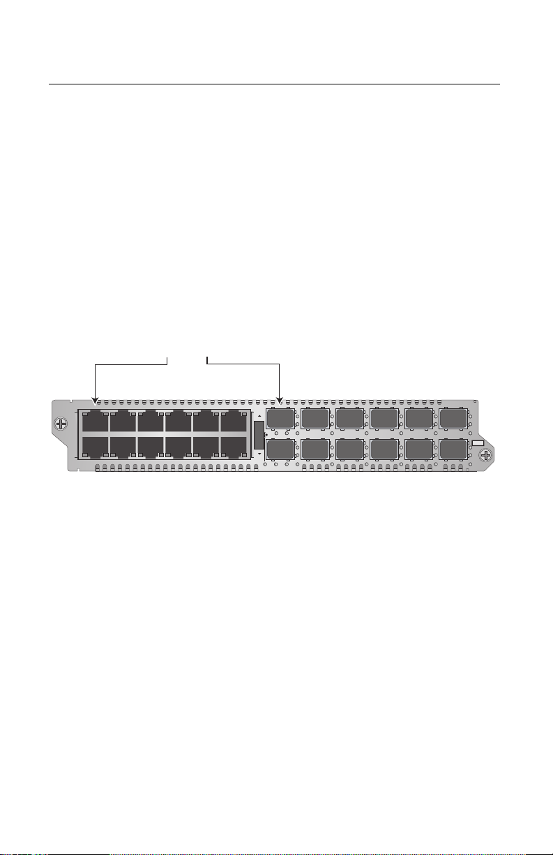
Media Converter Channels
The AT-MCF2012LC and AT-MCF2012LC/1 modules have
twelve independent media converter channels. Each
channel forwards Fast Ethernet network traffic between one
10/100Base-TX twisted pair port and one 100Base-FX fiber
optic port.
The channels are predefined. Channel 1 consists of twisted
pair port 1 and fiber optic port 1 (as shown in Figure 4),
channel 2 of twisted pair port 2 and fiber optic port 2, and so
forth. The port assignments of the channels cannot be
changed.
Channel 1
Twisted Pair Port 1 and
Fiber Optic Port 1
LA1
AT-MCF2012LC
LA23456789101112
LA
CH
CH
LA
1
TX RX
CDC FDC
TX RX
LT ML SML
3
5
7
9
11
L
L
L
A
A
CH1
CH3
4
L
A
CH2
6
L
A
CH4
L
A
A
CH5
CH7
8
L
L
A
A
CH6
CH8
TX RX
L
L
A
A
CH9
CH11
TX RX2
10
12
CLASS 1
LED PRODUCT
L
L
A
A
CH10
CH12
1119
Figure 4. Channel 1 on the Media Converter Module
Each channel operates independently of the other channels
on the same module and from channels on other modules in
the same chassis. As such, the traffic on the two ports of a
channel cannot crossover to the ports of another channel.
A channel uses “store and forward” to transfer packets
between its two ports. A packet is forwarded to the egress
port of a channel after it has been fully received and
buffered on the ingress port and checked for CRC errors.
Packets without a CRC error are forwarded to the egress
port where CRC is regenerated prior to the transmission of
the packet, while packets with CRC errors are discarded to
prevent their propagation on the network.
19
Page 20

Chapter 1: Overview
Twisted Pair Ports
The twisted pair ports feature standard RJ-45 8-pin
connectors and operate at either 10 or 100 Mbps in either
half- or full-duplex mode. The ports use TIA/EIA 568-Bcompliant Category 3 or better cable for 10 Mbps operation
and Standard TIA/EIA 568-A-compliant Category 5 or TIA/
EIA 568-B-compliant Enhanced Category 5 (Cat 5e) cable
for 100 Mbps operation. The ports have a maximum
operating distance of 100 meters. For port pinouts, refer to
“10/100Base-TX Port Pinouts” on page 62.
The ports are IEEE 802.3u. compliant. They can
automatically set their speed and duplex mode with AutoNegotiation, which is the default setting. To disable AutoNegotiation and set the speed and duplex mode manually,
you must install the optional management module in the
chassis.
In order for Auto-Negotiation to work properly, the
networking device connected to a twisted pair port on the
module should also use Auto-Negotiation. Otherwise, a
duplex mode mismatch can occur. A twisted pair port using
Auto-Negotiation will default to half-duplex if it detects that
the port on the networking device is not using AutoNegotiation. If the other networking device is operating at a
fixed duplex mode of full-duplex, the result will be a duplex
mode mismatch with the port on the module operating at
half-duplex and the port on the networking device at fullduplex. This can reduce network performance.
If you plan to connect a networking device that can operate
only in full-duplex mode to a twisted pair port on the media
converter module, you should disable Auto-Negotiation on
the port on the module using the optional management
module and set the speed and duplex mode manually.
Alternatively, you can reconfigure the port on the
networking device to Auto-Negotiation or, if it does not
support that feature, to half-duplex mode.
The twisted pair ports on the media converter module also
feature auto-MDI/MDI-X which automatically adjusts the
wiring configuration of a twisted pair port to either MDI or
MDI-X, depending on the wiring configuration of the end
node. This feature allows you to use a straight-through
twisted pair cable regardless of the wiring configuration of
the port on the networking device.
20
Page 21

AT-MCF2012LC and AT-MCF2012LC/1 Media Converter Modules Installation Guide
The auto-MDI/MDI-X feature is only available when a
twisted pair port is using Auto-Negotiation, the default
setting. If you disable Auto-Negotiation and set the port
speed and duplex mode manually, this feature is disabled
as well and the port defaults to the MDI-X setting. This may
require the manual configuration of the MDI/MDI-X setting
on the port or the use a crossover cable, depending on the
wiring configuration of the networking device connected to
the twisted pair port on the module.
21
Page 22

Chapter 1: Overview
Fiber Optic Ports
The fiber optic ports have duplex LC connectors. They are
100Base-FX compliant with a fixed operating speed of 100
Mbps. The duplex mode of these ports can be either half- or
full-duplex mode. The default setting is full duplex. Adjusting
the duplex mode of a fiber optic port requires the optional
management module for the chassis.
The fiber optic ports on the AT-MCF2012LC module have a
maximum operating distance of 2 km and use 50/125 or
62.5125 µm (core/cladding) multimode fiber optic cable.
The fiber optic ports on the AT-MCF2012LC/1 module have
a maximum operating distance of 20 km and use 9/125 µm
single-mode fiber optic cable.
Note
The maximum operating distances of the fiber optic
ports assume full-duplex operation. A fiber optic port
operating in half-duplex mode will have a maximum
operating distance that is significantly less.
Refer to “100Base-FX Fiber Optic Port Specifications” on
page 63 for the operating specifications of the fiber optic
ports.
22
Page 23

AT-MCF2012LC and AT-MCF2012LC/1 Media Converter Modules Installation Guide
LA1
3
AT-MCF2012LC
L
A
L
A
CH
CH
CH1
TX RX
1
TX RX2
3
4
CDC FDC
A
Port and Channel LEDs
The LEDs on the media converter module reflect packet
activity, link status, duplex mode and collisions of the ports,
as well as the operating mode of the channels.
“A” Activity
LED
Each port on the module has an Activity (A) LED, shown in
Figure 5. The Activity LED blinks to indicate when a port is
transmitting or receiving network packets from the
networking device connected to it.
Twisted Pair Port
Activity LED
Fiber Optic Port
Activity LED
Figure 5. Activity LEDs
The Activity LED is defined in Table 2.
Table 2. “A” Activity LED
Link LED
State
Description
Off The port is not receiving or transmitting network
packets.
Flashing
The port is receiving or transmitting packets.
Green
23
Page 24

Chapter 1: Overview
L
A
L
A
CH
CH
CH1
TX RX
1
TX RX2
3
4
CDC FDC
A
LA1
3
AT-MCF2012LC
“L” Link
LED
The twisted pair ports and fiber optic ports also have a Link
(L) LED, shown in Figure 6, for displaying the link status of a
port to its networking device. The meaning of a Link LED
can vary depending on the operating mode of a channel.
Consequently, you should first determine a channel’s
operating mode before deciphering the Link LEDs of a
channel’s two ports. It can also prove useful to consider the
Link LEDs of the two ports of a channel as a pair and to
view them as a unit.
For background information on the operating modes, refer
to “Channel Operating Modes” on page 31. For information
on viewing and setting the operating mode of a channel,
refer to “Mode Selection Button” on page 36.
Twisted Pair Port
Link LED
Fiber Optic Port
Link LED
Figure 6. “L” Link LEDs
24
Link LEDs and the Link Test Mode
The Link LED of a port in a channel set to the Link Test
mode reflects the current status of the link between the port
and its networking device. The Link LED is on when the port
has a link to its networking device and off when the port
does not have a link. For more information on this operating
mode, refer to “Link Test Mode” on page 31.
Table 3 lists the combinations and definitions of the Link
LEDs for the twisted pair port and fiber optic port of a
channel operating in the Link Test mode.
Page 25

AT-MCF2012LC and AT-MCF2012LC/1 Media Converter Modules Installation Guide
Table 3. “L” Link LEDs in the Link Test Mode
Channel Port
Link LED
State
Description
Twisted Pair Port Off Neither port in the channel has
established a link with its networking
Fiber Optic Port Off
Twisted Pair Port Steady
Green or
Amber
device.
Both ports in the channel have
established a link with a networking
device. The twisted pair port is
operating at 100 Mbps (green) or 10
Fiber Optic Port Steady
Green
Twisted Pair Port Steady
Green or
Amber
Fiber Optic Port Off
Mbps (amber) link and the fiber optic
port at 100 Mbps.
The twisted pair port in the channel
has established a 100 Mbps (green)
or 10 Mbps (amber) link with its
networking device, but the fiber optic
port has not established a link.
Twisted Pair Port Off The fiber optic port of the channel has
Fiber Optic Port Steady
Green
established a 100 Mbps link with its
networking device, but the twisted pair
port has not established a link.
Link LEDs and the MissingLink Mode
The Link LEDs of the ports of a channel set to the
MissingLink mode always work in tandem by being either
both on or off. This is because in the MissingLink mode the
two ports of a channel pass their “Link” status to each other
so that a change in link status on one port is replicated on
the companion port in the same channel. This means that a
port in a channel is not allowed to establish a link to its
networking device unless its companion port can also
establish a link with its device. For more information on this
operating mode, refer to “MissingLink Mode” on page 31.
Table 4 lists the combinations and definitions of the Link
LEDs for the twisted pair port and fiber optic port of a
channel operating in the MissingLink mode.
25
Page 26

Chapter 1: Overview
Table 4. “L” Link LEDs in the MissingLink Mode
Channel Port
Link LED
State
Description
Twisted Pair Port Off One or both ports in the channel can
not establish a link with a networking
Fiber Optic Port Off
Twisted Pair Port Steady
Green or
Amber
device.
Both ports in the channel have
established a link with a networking
device. The twisted pair port is
operating at 100 Mbps (green) or 10
Fiber Optic Port Steady
Green
Mbps (amber) link and the fiber optic
port at 100 Mbps.
Link LEDs and the Smart MissingLink Mode
The Smart MissingLink mode pulses the transmitter on a
port when its companion port in a channel loses or has not
established a link to its networking device. The blinking Link
LED can make it easier for you to identify and troubleshoot
a link problem on the two ports of a channel. For more
information on this operating mode, refer to “Smart
MissingLink Mode” on page 33.
Table 5 lists the combinations and definitions of the Link
LEDs for the twisted pair port and fiber optic port of a
channel operating in this mode.
Table 5. “L” Link LEDs in the Smart MissingLink Mode
Channel Port
Link LED
State
Description
Twisted Pair Port Off Neither port in the channel has
Fiber Optic Port Off
Twisted Pair Port Steady
Green or
Amber
Fiber Optic Port Steady
Green
26
established a link with a networking
device.
Both ports in the channel have
established a link with a networking
device. The twisted pair port is
operating at 100 Mbps (green) or 10
Mbps (amber) link and the fiber optic
port at 100 Mbps.
Page 27

AT-MCF2012LC and AT-MCF2012LC/1 Media Converter Modules Installation Guide
Table 5. “L” Link LEDs in the Smart MissingLink Mode (Continued)
Channel Port
Twisted Pair Port Flashing
Fiber Optic Port Off
Link LED
State
Green or
Amber
Description
The twisted pair port of the channel
can establish a 100 Mbps (green) or
10 Mbps (amber) link with its
networking device, but the fiber optic
port is unable to establish a link with
its remote device. For troubleshooting
suggestions, refer to Problem 4 in
Chapter 3, “Troubleshooting” on page
55.
Twisted Pair Port Off The fiber optic port of a channel can
establish a 100 Mbps link with its
Fiber Optic Port Flashing
Green
networking device, but the twisted pair
port is unable to establish a link with
its local device. For troubleshooting
suggestions, refer to Problem 3 in
Chapter 3, “Troubleshooting” on page
55.
Twisted Pair Port Flashing
Green or
Amber
Both ports in the channel can
establish a link to a networking device,
but one of the ports is connected to
another media converter that also
Fiber Optic Port Flashing
Green
supports the Smart MissingLink
feature, forming a chain of converters.
A link has been lost on one of the
ports in the chain, causing a ripple
affect through the chain of converters.
Alternatively, one of the ports is only
able to form an intermittent link with its
networking device.
For troubleshooting suggestions, refer
to Problem 8 in Chapter 3,
“Troubleshooting” on page 55.
27
Page 28

Chapter 1: Overview
A
L
A
CH
CH
CH1
TX RX24
CDC FDC
CDC and
FDC Duplex
Mode and
Collision
LEDs
LA1
AT-MCF2012LC
LA23456789101112
The CDC and FDC LEDs shown in Figure 7 display the
duplex mode of the ports in a channel and, for ports
operating in half-duplex mode, the collisions. The CDC
(Copper, Duplex mode, Collisions) LED displays this
information for the twisted pair port of a channel, while the
FDC (Fiber optic, Duplex mode, Collisions) LED displays
the same information for the fiber optic port.
1
3
5
7
9
11
LA
CH
CH
LA
LT ML SML
TX RX
TX RX
CDC FDC
L
L
L
A
A
CH1
CH3
4
L
A
CH2
6
L
A
CH4
L
A
A
CH5
CH7
8
L
L
A
A
CH6
CH8
TX RX
L
L
A
A
CH9
CH11
TX RX2
10
12
CLASS 1
LED PRODUCT
L
L
A
A
CH10
CH12
Figure 7. CDC and FDC Duplex Mode and Collisions LEDs
The LEDs can display the status of the ports of only one
channel at a time. To use the LEDs you must first select a
channel with the Mode Selection button, explained in “Mode
Selection Button” on page 36. The selected channel is
indicated with the CH LEDs beneath the fiber optic ports.
The CDC and FDC LEDs display the status of a channel’s
ports as soon as a channel is selected. For example, if you
select channel 4 (CH4), the CDC and FDC LEDs reflect the
duplex mode and collisions for twisted pair port 4 and fiber
optic port 4 on the module, respectively.
28
Page 29

AT-MCF2012LC and AT-MCF2012LC/1 Media Converter Modules Installation Guide
The CDC and FDC LEDs are described in Table 6.
Table 6. CDC and FDC Duplex Mode and Collisions LEDs
LED State Description
CDC Off The twisted pair port in the channel has not
established a link with its networking device.
Steady
Green
Steady
Amber
Flashing
The twisted pair port is operating in full-duplex
mode.
The twisted pair port is operating in half-duplex
mode.
Collisions are occurring on the twisted pair port.
Amber
FDC Off The fiber optic port in the channel has not
established a link with its networking device.
Steady
Green
Steady
Amber
Flashing
The fiber optic port is operating in full-duplex
mode.
The fiber optic port is operating in half-duplex
mode.
Collisions are occurring on the fiber optic port.
Amber
29
Page 30

Chapter 1: Overview
A
CH
CH2
LT ML SML
LT, ML, and
SML
Channel
Operating
Mode LEDs
LA1
AT-MCF2012LC
LA23456789101112
The LT, ML, and SML LEDs shown in Figure 7 display the
operating mode of a media converter channel. The
operating mode can be Link Test (LT), MissingLink (ML), or
Smart MissingLink (SML). The LEDs can display the mode
of only one channel at a time. To select a channel, refer to
“Mode Selection Button” on page 36. For a description of
the channel operating modes, refer to “Channel Operating
Modes” on page 31.
1
3
5
7
9
LA
LA
CH
CH
TX RX
CDC FDC
TX RX
LT M L SML
L
L
L
A
A
CH1
CH3
4
L
A
CH2
6
L
A
CH4
L
A
A
CH5
CH7
8
L
L
A
A
CH6
CH8
11
TX RX
L
L
A
A
CH9
CH11
TX RX2
10
12
CLASS 1
LED PRODUCT
L
L
A
A
CH10
CH12
LT, ML, and SML Channel Operating Mode LEDs
30
Page 31

AT-MCF2012LC and AT-MCF2012LC/1 Media Converter Modules Installation Guide
Channel Operating Modes
A media converter channel has three operating modes. The
operating modes are:
Link Test mode
MissingLink mode
Smart MissingLink mode
The operating mode of a channel is set with the Mode
Selection button on the front panel of the module, as
explained in “Mode Selection Button” on page 36 or with the
optional management module for the chassis.
Link Test
Mode
MissingLink
Mode
Contrary to its name, the Link Test operating mode does not
test anything. Rather, what it does is it reflects the current
status of the link between a channel port and its networking
device on the port’s Link LED. The Link LED of a port in the
channel will be on when the port has a link to its networking
device and off when the port does not have a link. (Refer to
Table 3 on page 25.)
This mode does not interfere with the flow of traffic between
the two ports of a channel and so can be used during
normal network operations of a channel. This mode is
typically used when the networking devices connected to a
channel cannot take advantage of the features of the
MissingLink mode, or when you want to use the Link LEDs
of the ports of a channel to troubleshoot a network problem.
This operating mode is also useful after the installation of a
media converter module to verify whether the ports of a
channel have successfully established a link with a
networking device. This is explained in “Verifying the
Installation” on page 53.
The MissingLink mode enables the twisted pair port and the
fiber optic port of a channel on the media converter module
to pass the “Link” status of their connections to each other.
This ensures that both ports of a channel and,
consequently, the networking devices connected to the
ports, are always aware of a change to the status of the link
of the companion port in a channel.
When a channel in the MissingLink mode detects the loss of
a link on one of its ports, it replicates the loss on the
companion port in the same channel by disabling the
31
Page 32

Chapter 1: Overview
transmitter on the companion port. This notifies the
networking device connected to the port of the loss of the
link on the other channel port.
Without the MissingLink mode, a networking device
connected to a port on the media converter will not be
aware of a loss of a link on a companion port in the channel,
because its link to the media converter would be unaffected.
When the link is reestablished on a port of a channel, the
MissingLink mode automatically reactivates the transmitter
on the companion port so that the two networking devices
can again forward traffic to each other through the two ports
of the media converter channel.
The value to this type of fault notification is that some
networking devices, such as managed Fast Ethernet
switches, can respond to the loss of a link on a port by
performing a specific action. For example, the networking
device might send a trap to a network management station,
and so alert the network administrator of the problem. Or, if
the device is running a spanning tree protocol, it might seek
a redundant path to a disconnected node.
Here is an example of how the MissingLink mode works.
Assume that the two ports of a channel are connected to
two Fast Ethernet switches, one local and the other remote.
Switch A, the local switch, is connected to the twisted pair
port of the channel, while Switch B, the remote device, is
connected to the fiber optic port.
If the link to Switch A is lost on the twisted pair cable, the
media converter disables the transmitter on the fiber optic
port in the same channel to signal Switch B of the loss of
the link to Switch A. This notifies Switch B of the problem so
that it too, along with Switch A, can take remedial action,
such as activating a redundant path if it is running a
spanning tree protocol or sending an SNMP trap to a
management workstation if it is using SNMP. Without the
MissingLink mode, switch B would continue to assume that
it still has a valid link to the remote device on the other side
of the media converter channel since its link to the port on
the channel is still valid, though no remote traffic is
received.
In the example, the initial loss occurred on the twisted pair
port. But the mode operates the same when the initial loss
of the link is on the fiber optic port of a channel. Here, the
transmitter on the twisted pair port is disabled to notify the
32
Page 33

AT-MCF2012LC and AT-MCF2012LC/1 Media Converter Modules Installation Guide
node connected to that port of the loss of the link on the
fiber optic port.
The Link LEDs of the ports in a channel running in this
mode always operate in tandem, as shown in Table 4 on
page 26. They can be both on or off. Both Link LEDs of the
ports of a channel operating in this mode remain off until
both ports can establish a link with their networking device.
This operating mode is useful when the networking devices
connected to the ports of a channel can react to a loss of a
link on a port, such as managed Fast Ethernet switches
running SNMP or a spanning tree protocol. Conversely, the
MissingLink mode will be of little value if the networking
devices of a channel cannot react to a lost link. In the latter
scenario, it would probably be better to set a channel to the
Link Test mode, instead, during normal network operations.
Furthermore, Allied Telesis does not recommend using the
MissingLink mode when troubleshooting a network problem
that may have its roots with a link problem. The MissingLink
mode will not allow you to use the Link LEDs of the ports in
a channel to diagnose the problem. Rather, the Link Test
and the Smart MissingLink modes are more useful when
troubleshooting a link problem.
Smart
MissingLink
Mode
The Smart MissingLink mode, the third operating mode of
the media converter channels, is nearly identical in terms of
functionality to the MissingLink mode. It, too, enables the
ports of a channel to pass the “Link” status of their
connections to each other so that both ports reflect the
same link status.
The difference is that rather than completely shutting off the
transmitter of a port when its companion port in a channel
loses its link, this operating mode pulses the port’s
transmitter and blinks the port’s Link LED every second.
This signals the port’s ability to still establish a link to its
networking device and that the loss of the link originated on
the companion port in the channel.
This difference allows you to use the Link LEDs of the ports
to troubleshoot a link failure. In contrast, when a channel is
operating in the MissingLink mode you cannot use the Link
LEDs of the ports to troubleshoot a link problem because
both LEDs will be off when one port loses its link.
For a definition of the Link LEDs when a channel is
operating in this mode, refer to Table 5 on page 26.
33
Page 34

Chapter 1: Overview
Here is an example of how the Smart MissingLink mode
works. Assume that the fiber optic port in a media converter
channel lost its link to its networking device while the
channel was in the Smart MissingLink operating mode. The
mode would respond by pulsing the transmitter on the
twisted pair port of the channel about once a second, and
flashing the port’s Link LED. This would signal that the port
can still establish a link with its networking device and that
the failure originated on the fiber optic port. When the
connection is reestablished on the fiber optic port, the
twisted pair port resumes normal operations so that the two
ports can again forward traffic to each other.
The operating mode functions the same if the failure starts
on the twisted pair port. Here, the mode pulses the
transmitter on the fiber optic port and blinks the port’s Link
LED.
As with the other two channel operating modes, this mode
does not interfere with the flow of network traffic through the
ports of a channel and so can be used during normal
network operations of a media converter channel. However,
you might want to limit its use to diagnosing a link failure,
particularly if the networking devices connected to the ports
are managed devices. This is because the pulsing of the
transmitter on a port and the constantly changing status of a
link could prove problematic for some managed devices.
For example, the device might send a constant stream of
SNMP traps or, if the device is running a spanning tree
protocol, the protocol may become confused as the status
of the device’s link to the media converter constantly
changes.
34
Page 35

AT-MCF2012LC and AT-MCF2012LC/1 Media Converter Modules Installation Guide
Guidelines to
Using the
Channel
Operating
Modes
Here are the guidelines to using the channel operating
modes:
Different channels on the module can operate in
different modes.
The operating modes do not block or interfere with the
flow of traffic between the two ports of a channel, and so
can be used during normal network operations.
The MissingLink mode is intended for situations where
the ports of a channel are connected to managed
devices, such as managed Fast Ethernet switches, that
can react to the loss of a link and perform a specific
action, such as send out an SNMP trap.
Allied Telesis does not recommend using the Smart
MissingLink mode on a channel connected to managed
devices during normal operations of the channel. As
explained in “Smart MissingLink Mode” on page 33, this
mode pulses the transmitter of a channel port when the
link is lost on the companion port. A pulsing transmitter
may cause problems for a managed device.
The Link Test and Smart MissingLink modes are
particularly useful when there has been a link failure to a
channel port and you want to use the Link LEDs to
identify which port in a channel is unable to establish a
link with its networking device.
35
Page 36

Chapter 1: Overview
CH
CH
TX RX2
CDC
Mode Selection Button
The Mode Selection button shown in Figure 8 serves two
purposes. One is to set the operating mode of a channel.
The three operating modes are described in “Channel
Operating Modes” on page 31. The other is to view the
duplex mode and collisions on the ports of a channel with
the CDC and FDC LEDs, explained in “CDC and FDC
Duplex Mode and Collision LEDs” on page 28,
LA1
AT-MCF2012LC
LA23456789101112
LA
LA
CH
CH
1
TX RX
CDC FDC
TX RX
LT M L SML
3
5
7
9
11
L
L
L
A
A
CH1
CH3
4
L
A
CH2
6
L
A
CH4
L
A
A
CH5
CH7
8
L
L
A
A
CH6
CH8
TX RX
L
L
A
A
CH9
CH11
TX RX2
10
12
CLASS 1
LED PRODUCT
L
L
A
A
CH10
CH12
Figure 8. Mode Selection Button
Before you can set the operating mode of a channel or view
the duplex mode and collisions on the ports of a channel,
you must first select the channel. You accomplish this by
turning the Mode Selection button up or down to toggle
through the channels. Channel selection is indicated by the
CH LEDs beneath the fiber optic ports. You can select only
one channel at a time.
After you have selected a channel, the duplex mode setting
and collisions on the two ports of the selected channel are
immediately reflected on the CDC and FDC LEDs.
To set the operating mode of a channel, press the middle of
the button to toggle the channel between Link Test (LT),
MissingLink (ML), and Smart MissingLink (SML). The
36
operating mode of a channel is reflected by the LT, ML, and
Page 37

AT-MCF2012LC and AT-MCF2012LC/1 Media Converter Modules Installation Guide
SML LEDs, explained in “LT, ML, and SML Channel
Operating Mode LEDs” on page 30. A change of the
operating mode is immediately activated on a channel.
Here is an example on how to use the Mode Selection
button. Assume you wanted to determine the duplex mode
of the two port in channel 6 (i.e., twisted pair port 6 and fiber
optic port 6) and change the operating mode of the channel
to the Link Test mode. The first step is select channel 6 by
turning the Mode Selection button up or down to toggle the
CH LEDs until the CH6 LED under fiber optic port 6 is on. At
that point the CDC and FDC LEDs immediately reflect the
duplex mode and collisions for the two ports of channel 6.
To change the operating mode of the channel to the Link
Test mode, you press the button to toggle the operating
mode LEDs until the LT LED is on.
Note
Using the Mode Selection button to view the CDC and
FDC LEDs and to change the operating mode of a
channel does not interfere with the forwarding of traffic
by the channels on the module.
37
Page 38

Chapter 1: Overview
Guidelines to Using the Media Converter Module
This section lists the factors to be considered as part of the
planning process prior to the installation of an
AT-MCF2012LC or AT-MCF2012LC/1 media converter
module.
In order for local and remote networking devices to
forward traffic to each other through the media converter
module, they must be connected to ports of the same
channel. Naturally, the local networking device is
attached to the twisted pair port of the channel and the
remote networking device is connected to the fiber optic
port.
As explained in “Media Converter Channels” on
page 19, the ports of a channel are predefined. Channel
1 consists of twisted pair port 1 and fiber optic port 1,
channel 2 of twisted pair port 2 and fiber optic port 2,
and so forth. The channel assignments cannot be
changed.
You can use the media converter channels in any order.
Since the twisted pair port of a channel can operate at
either 10 or 100 Mbps while the fiber optic port has a
fixed speed of 100 Mbps, the local and remote
networking devices of a channel can operate at different
speeds. The networking devices must use backpressure
or flow control, depending on the duplex mode, to
control the flow of packets to each other through the
channel ports.
A media converter channel performs best when both the
local and remote networking devices and the two ports
of the channel are all operating with the same duplex
mode of either half- or full-duplex. A channel may have
to discard packets if its ports are operating in different
modes, causing the networking devices to have to
frequently retransmit packets.
For example, if one of the networking devices
connected to a port of a media converter channel is only
capable of half-duplex mode, then both ports of the
channel and the other networking device connected to
the companion port in the channel should operate in
half-duplex mode, too.
38
Page 39

AT-MCF2012LC and AT-MCF2012LC/1 Media Converter Modules Installation Guide
During normal network operations, a media converter
channel can operate in any of the three operating
modes. For an explanation of the modes, refer to
“Channel Operating Modes” on page 31.
The default setting for a twisted pair port on the media
converter module is Auto-Negotiation and auto-MDI/
MDI-X.
The default duplex mode setting for a fiber optic port is
full-duplex.
Changing the settings of a port on the media converter
module requires the optional management module.
There are no adjustable switches on the circuit boards
of the AT-MCF2012LC and AT-MCF2012LC/1 media
converter modules.
39
Page 40

Chapter 1: Overview
40
Page 41

Chapter 2
Installation
This chapter contains the following sections:
“Reviewing Safety Precautions” on page 42
“Planning the Installation” on page 44
“Unpacking the Media Converter Module” on page 46
“Installing the Media Converter Module” on page 47
“Cabling the Media Converter Module” on page 52
“Verifying the Installation” on page 53
For instructions on how to install the chassis, refer to the
Installation Guide that ships with the chassis.
Note
The following procedures use the AT-MCF2000
chassis for illustration purposes. Your chassis may be
different.
41
Page 42

Chapter 2: Installation
Reviewing Safety Precautions
Please review the following safety precautions before you
begin to install the media converter module.
Note
The indicates that a translation of the safety
statement is available in a PDF document titled
“Translated Safety Statements” (613-000405) posted
on the Allied Telesis website at www.alliedtelesis.com.
Warning: Class 1 Laser product.
(AT-MCF2012LC/1 module)
Class 1 LED product. (AT-MCF2012LC module)
2
1
Warning: Do not stare into the laser beam.
Warning: Do not work on equipment or cables
during periods of lightning activity.
Warning: Electrical-Type Class 1 Equipment:
This equipment must be earthed. The power
plug must be connected to a properly wired earth
ground socket outlet. An improperly wired socket
outlet could place hazardous voltages on
accessible metal parts. 7
Pluggable Equipment. The socket outlet shall be
installed near the equipment and shall be easily
accessible.
Caution: Air vents must not be blocked and
must have free access to the room ambient air
for cooling. 9
Warning: Operating Temperature. This product
is designed for a maximum ambient temperature
of 40° degrees C.
8
10
3
5
42
Page 43

AT-MCF2012LC and AT-MCF2012LC/1 Media Converter Modules Installation Guide
All Countries: Install product in accordance with
local and National Electrical Codes. 11
Warning: Only trained and qualified personnel
are allowed to install or to replace this
equipment. 17
Caution: Do not install in direct sunlight, or a
damp or dusty place.
19
Caution: Do not expose the gateway device to
moisture or water. 20
Warning: Mounting of the equipment in the rack
should be such that a hazardous condition is not
created due to uneven mechanical loading.
28
Caution: Installation of the equipment in a rack
should be such that the amount of air flow
required for safe operation of the equipment is
not compromised.
40
43
Page 44

Chapter 2: Installation
Planning the Installation
10/100Base-
TX Twisted
Pair Cabling
Table 7 lists the cable requirements for the 10/100Base-TX
twisted pair ports. For port pinouts, refer to “10/100Base-TX
Port Pinouts” on page 62.
Table 7. Twisted Pair Cable and Distances
Maximum
Speed Cable Type
10 Mbps Standard TIA/EIA 568-B-
compliant Category 3 or
better shielded or
unshielded cabling with
100 ohm impedance and
a frequency of 16 MHz.
100 Mbps Standard TIA/EIA 568-A-
compliant Category 5 or
TIA/EIA 568-B-compliant
Enhanced Category 5
(Cat 5e) shielded or
unshielded cabling with
100 ohm impedance and
a frequency of 100 MHz.
Operating
Distance
100 m (328 ft)
100 m (328 ft)
Note
The default setting for a twisted pair port is AutoNegotiation and auto-MDI/MDI-X. In the default
setting, a port’s speed, duplex mode, and MDI/MDI-X
setting are set automatically. Disabling AutoNegotiation and manually configuring a port requires
the optional management module for the chassis.
44
Page 45

AT-MCF2012LC and AT-MCF2012LC/1 Media Converter Modules Installation Guide
Fiber Optic
Cabling
The fiber optic ports on the AT-MCF2012LC and
AT-MCF2012LC/1 media converters have duplex LC
connectors.
Table 8 lists the cable requirements for the fiber optic ports
on the AT-MCF2012LC module. (For the optical
specifications, refer to “100Base-FX Fiber Optic Port
Specifications” on page 63.)
Table 8. AT-MCF2012LC Fiber Optic Cable
Maximum
Cable Type
50/125 µm or 62.5/125 µm (core/
cladding) multimode fiber optic
cable
Table 9 lists the cable specifications for the fiber optic ports
on the AT-MCF2012LC/1 module. (For the optical
specifications, refer to “100Base-FX Fiber Optic Port
Specifications” on page 63.)
Table 9. AT-MCF2012LC/1 Fiber Optic Cable
Cable Type
Operating
Distance
2 km (1.24 mi.)
Maximum
Operating
Distance
9/125 µm single-mode fiber optic
cable
Note
The fiber optic ports have a fixed speed of 100 Mbps
and can operate in either half or full-duplex mode. The
default setting is full-duplex mode. To change the
duplex mode requires the optional management
module for the chassis.
Note
The maximum operating distances of the fiber optic
ports assume full-duplex mode operation. The
distance will be significantly less for a fiber optic port
operating in half-duplex mode.
20 km (12.4 mi.)
45
Page 46

Chapter 2: Installation
Unpacking the Media Converter Module
To unpack the module, perform the following procedure:
1. Remove all components from the shipping package.
Note
Store the packaging material in a safe location. You
must use the original shipping material if you need to
return the unit to Allied Telesis.
2. Verify that the following items are included in the
shipping package. If an item is missing or damaged,
contact your Allied Telesis sales representative for
assistance.
One AT-MCF2012LC or AT-MCF2012LC/1 Media
Converter Module
This installation guide
46
Page 47

AT-MCF2012LC and AT-MCF2012LC/1 Media Converter Modules Installation Guide
Installing the Media Converter Module
Caution
A media converter module is sensitive to and can be
damaged by electrostatic discharge. Wear a
grounding device and observe electrostatic discharge
precautions when installing a media converter module
in the chassis.
Note
The AT-MCF2012LC and AT-MCF2012LC/1 modules
support hot swapping. They can be installed while the
chassis is powered on.
Note
There are no adjustable switches on the circuit boards
of the AT-MCF2012LC and AT-MCF2012LC/1
modules.
To install the media converter module, perform the following
procedure:
1. Select a slot in the chassis for the media converter
module. Refer to the chassis’ Installation Guide for the
number and location of the media converter module
slots.
Note
Unless the chassis’ Installation Guide states
otherwise, the AT-MCF2012LC and AT-MCF2012LC/1
media converter modules can be installed in any
available media converter module slot in the chassis.
2. Using a cross-head screwdriver, loosen the two captive
screws that secure the blank panel over the media
converter slot and remove the panel from the chassis.
Refer to Figure 9.
47
Page 48

Chapter 2: Installation
Note
Do not remove a blank panel from the chassis until
you are ready to install a module. An open slot allows
dust to enter the unit and impedes the ability of the
chassis to maintain proper airflow and cooling.
A
T-M
C
F
2
0
0
0
1
AT-MCF2000
2
1120-a
Figure 9. Removing a Blank Panel from a Media Converter
Slot
3. Unpack the media converter module from its shipping
container.
Note
Store the packaging material in a safe location. You
must use the original shipping material should you
need to return the unit to Allied Telesis.
48
Page 49

AT-MCF2012LC and AT-MCF2012LC/1 Media Converter Modules Installation Guide
4. Remove the insulator labelled “REMOVE BEFORE
INSTALL” from the battery on the media converter
module by sliding it out from beneath the battery clip.
Refer to Figure 10.
Caution
A media converter module is sensitive to and can be
damaged by electrostatic discharge. Wear a
grounding device and observe electrostatic discharge
precautions when removing the battery insulator.
Battery Insulator
1169b
Figure 10. Removing the Battery Insulator
49
Page 50

Chapter 2: Installation
1
A
T-M
C
F
2
0
0
0
5. Align the edges of the module with the guides in the
slot and carefully slide the module into the chassis until
it is flush with the front of the chassis. Refer to Figure
11. Light pressure may be necessary to firmly seat the
module connector on the connector on the back panel
of the chassis.
Caution
Do not force the module into place. Doing so may
damage the connector pins on the backplane of the
chassis. If there is resistance, remove the module and
reinsert it after verifying that the edges of the card are
properly aligned with the guides in the chassis’
module slot.
AT-MCF2012LC
1121-a
Figure 11. Installing the Media Converter Module
50
Page 51

AT-MCF2012LC and AT-MCF2012LC/1 Media Converter Modules Installation Guide
1122-a
6. Secure the media converter module to the chassis by
tightening the two captive screws on the module using
a cross-head screwdriver. Refer to Figure 12.
AT-MCF2012LC
1
Figure 12. Securing the Media Converter Module
7. If this is the initial installation of the media converter
chassis, return to the chassis’ Installation Guide and
perform the remaining procedures to complete the
installation. Otherwise, continue to the next procedure
to attach the network cables to the ports on the media
converter module.
51
Page 52

Chapter 2: Installation
Cabling the Media Converter Module
You may find it useful to first review the information in
“Media Converter Channels” on page 19 and “Guidelines to
Using the Media Converter Module” on page 38 prior to
connecting the network cables to the module.
Observe the following guidelines when connecting a cable
to a twisted pair port:
An RJ-45 connector should fit snugly into the port on the
module and the tab on the connector should lock the
connector into place.
A local device and a remote device must be connected
to the ports in the same channel to forward traffic to
each other through the media converter. For further
information, refer to “Media Converter Channels” on
page 19.
The default setting for a twisted pair port is Auto-
Negotiation and auto-MDI/MDI-X.
In order for Auto-Negotiation to function properly on a
twisted pair port and to prevent a duplex mode
mismatch, the networking device connected to the port
should also be using Auto-Negotiation. For further
information, refer to “Twisted Pair Ports” on page 20.
Observe the following guidelines when connecting a fiber
optic cable to a fiber optic port:
Do not remove the dust cover from a fiber optic port until
you are ready to connect the cable. Dust contamination
can adversely impact the operation of the port.
Review the information in “Fiber Optic Cabling” on
page 45 to verify that you are using the correct type of
fiber optic cable and are not exceeding the operating
distance of the fiber optic port.
Verify that the operating specifications of the module’s
fiber optic port are compatible with the fiber optic port on
the networking device. For port specifications, refer to
“100Base-FX Fiber Optic Port Specifications” on
page 63.
The connector on the fiber optic cable should firmly lock
into place on the port.
52
Page 53

AT-MCF2012LC and AT-MCF2012LC/1 Media Converter Modules Installation Guide
Verifying the Installation
This procedure verifies the installation of the media
converter module by determining whether the ports in the
channels can establish a link to their networking devices.
This procedure assumes the following:
The media converter chassis is powered on.
The network cables are connected to the ports on the
media converter module and to the local and remote
networking devices.
The local and remote networking devices are powered
on.
To verify the installation of a media converter module,
perform the following procedure:
1. Select a channel on the module using the Mode
Selection button, as explained in “Mode Selection
Button” on page 36. Channel selection is indicated by
the CH LEDs next to the fiber optic ports. Turning the
button up or down toggles through the channels. For
example, to select channel 1 (i.e., twisted pair port 1
and fiber optic port 1), turn the Mode Selection button
until the CH1 LED is on.
2. Set the operating mode of the channel to Link Test by
pressing the middle of the Mode Selection button until
the LT LED is on.
3. Observe the Link LEDs of the twisted pair and fiber
optic ports of the channel.
If the Link LEDs for both ports of the channel are
on, the ports have established a link with their
networking device. The local and remote devices
may already be forwarding network traffic to each
other through the media converter channel. You
can either leave the channel in the Link Test mode
during normal operations or, by pressing the
middle of the Mode Selection button again, change
it to the MissingLink or Smart MissingLink mode.
The MissingLink mode is active on a channel
when the ML LED is on. The Smart MissingLink
mode is active on a channel when the SML LED is
on. For further information on the operating
modes, refer to “Channel Operating Modes” on
53
Page 54

Chapter 2: Installation
page 31.
If a Link LED for a port in the channel is off, the
port is unable to establish a link to its networking
device. For suggestions on how to resolve the
problem, go to Chapter 3, “Troubleshooting” on
page 55.
4. Repeat this procedure to test the ports in the other
channels.
54
Page 55

Chapter 3
Troubleshooting
This chapter contains suggestions on how to troubleshoot
the AT-MCF2012LC and AT-MCF2012LC/1 media
converter modules should a problem occur. For
suggestions on how to troubleshoot a problem with the
chassis, refer to the Installation Guide that ships with the
chassis.
Problem 1: Cables are connected to the ports on the
media converter module and the chassis is powered on,
but all of the port LEDs on the module are off.
Solution: Examine the LT, ML, and SML LEDs on the
module. One of the LEDs should be on, as well one of the
CH LEDs, even when no cables are attached to a module.
A failure of all the LEDs could mean that the module is not
receiving power or has failed. Try the following:
Remove the media converter module and reinstall it.
Determine whether the power supply in the chassis is
Install the media converter module in another slot in
Replace the media converter module.
operating by listening for the fans. If the fans are not
operating, the problem is with the power supply. Refer
to the chassis’ Installation Guide for assistance in
troubleshooting a problem with the power supply.
the chassis.
Problem 2: The two ports of a channel are connected to
networking devices, but the Link LEDs for the ports are off.
Solution: The first step to resolving a link problem
between the ports of a channel and the networking
devices is to set the operating mode of the channel to the
Smart MissingLink mode or the Link Test mode. These
modes allow you to use the Link LEDs to identify which
port in a channel is unable to establish a link to its
networking device. The operating mode of a channel is set
with the Mode Selection button, as explained in “Mode
Selection Button” on page 36.
55
Page 56

Chapter 3: Troubleshooting
After setting the channel to the Smart MissingLink or Link
Test mode, observe the Link LEDs for the ports of the
channel again. If the Link LED for the twisted pair port is off,
go to Problem 3. If the Link LED for the fiber optic port is off,
go to Problem 4.
Problem 3: The Link LED for the fiber optic port in a
channel is on or blinking, but the Link LED for twisted pair
port of the same channel is off.
Solution: The twisted pair port of the channel has failed to
establish a link with its networking device. Try the following:
Verify that the networking device connected to the
twisted pair port is powered on and operating properly.
Verify that the twisted pair cable is securely connected
to the port on the media converter channel and the port
on the remote networking device.
Verify that the correct twisted pair cable is connected to
the port in the channel. This is to eliminate the possibility
that an unused twisted pair cable was inadvertently
connected to the port or that the cable is connected to
the wrong remote networking device, such as a
powered off device.
Try connecting another networking device to the twisted
pair port with a different cable. If the twisted pair port is
able to establish a link, then the problem is with the
cable or the other networking device.
If you installed the optional management module in the
chassis, use the management software to verify that the
port is enabled.
Problem 4: The Link LED of the twisted pair port in a
channel is on or blinking, but the Link LED of the fiber optic
port in the same channel is off.
Solution: The fiber optic port of the channel is unable to
establish a link to its networking device. Try the following:
Verify that the networking device connected to the fiber
optic port is operating properly.
Verify that the fiber optic cable is securely connected to
the port on the media converter channel and the port on
the remote networking device.
Verify that the operating specifications of the fiber optic
port on the remote networking device are compatible
with the port on the media converter module. For port
56
Page 57

AT-MCF2012LC and AT-MCF2012LC/1 Media Converter Modules Installation Guide
specifications, refer to “100Base-FX Fiber Optic Port
Specifications” on page 63.
Verify that the correct type of fiber optic cabling is being
used. For specifications, refer to “Fiber Optic Ports” on
page 22 or “100Base-FX Fiber Optic Port
Specifications” on page 63.
Verify that the correct fiber optic cable is connected to
the port in the channel. This is to eliminate the possibility
that an unused fiber optic cable was inadvertently
connected to the port or that the cable is connected to
the wrong remote networking device, such as a
powered off device. For background information, refer to
“Media Converter Channels” on page 19.
Try connecting another networking device to the fiber
optic port using a different cable. If the twisted pair port
is able to establish a link, then the problem is with the
cable or the other networking device.
If you installed the optional management module in the
chassis, use the management software to verify that the
port is enabled.
If the remote networking device is a management
device, use its management firmware to determine
whether its port is enabled.
Test the attenuation on the fiber optic cable with a fiber
optic tester to determine whether the optical signal is too
weak (i.e., sensitivity) or too strong (i.e., maximum input
power). The specifications of the fiber optic ports on the
media converter module can be found in “100Base-FX
Fiber Optic Port Specifications” on page 63.
Problem 5: The Link LEDs for the two ports of a channel
are on but the networking devices are unable to forward
traffic to each other through the channel.
Solution: Try the following:
Verify that the twisted pair and fiber optic cables from
the two networking devices are connected to ports of
the same channel. This is to eliminate the possibility that
the devices were inadvertently connected to ports in
different channels. For background information, refer to
“Media Converter Channels” on page 19.
If the networking devices are managed devices, use
their management firmware to determine whether they
are configured and operating properly.
57
Page 58

Chapter 3: Troubleshooting
If one or both of the networking devices are using a
spanning tree protocol, use their management firmware
to determine the status of the port connected to the
media converter channel. The port may have been
placed in the standby mode by the switch if it
represented a redundant path.
Problem 6: Two networking devices are forwarding traffic
through a channel of the media converter module, but
performance is slow.
Solution: Try the following:
There might be a duplex mode mismatch between the
twisted pair port in the channel and the networking
device connected to the port. As explained in “Twisted
Pair Ports” on page 20, a duplex mode mismatch occurs
when a twisted pair port using Auto-Negotiation is
connected to a device with a fixed duplex mode of full
duplex. If this is the cause of the problem, you must
adjust the duplex mode of the port on the networking
device or the twisted pair port on the media converter so
that both ports are using the same duplex mode.
The two networking devices are operating in different
duplex modes. As explained in “Guidelines to Using the
Media Converter Module” on page 38, a channel
performs best when its two networking devices and its
two ports all use the same duplex mode.
There could be an intermittent problem with one of the
networking devices connected to a port of the channel
or with a cable. To determine whether this might be the
problem, set the channel to the Link Test mode and
observe the Link LEDs of the ports. If one of the Link
LEDs periodically blinks, it could mean that the link is
intermittent. See Problem 7 for suggestions on how to
resolve this issue.
Problem 7: A channel is operating in the Link Test mode
and the Link LED of a port is blinking.
Solution: This could indicate that the link between the port
and the networking device is intermittent. There might be a
problem with the cable or the networking device connected
to the port. Try connecting another networking device with a
different cable to the same port on the media converter
module. If the Link LED remains steady on, then the
problem is indeed with the original cable or the networking
device.
58
Page 59

AT-MCF2012LC and AT-MCF2012LC/1 Media Converter Modules Installation Guide
Problem 8: A channel is operating in the Smart MissingLink
mode and the Link LEDs for both ports are blinking.
Solution: This could have several possible causes. This
can occur when a port of the channel is connected to
another media converter that also supports the Smart
MissingLink mode, forming a chain of media converters.
Media converters that support the Smart MissingLink mode
will pass the loss of a link on a port to all the media
converters in the chain. This can result in situations where
the Link LEDs on both ports of a media converter are
blinking, indicating that the source of the problem has its
origins in another media converter in the chain. To identify
the source of the problem, set the operating mode on all the
media converters in the chain to Link Test and then
examine the Link LEDs of the ports. The Link LED of the
port that cannot establish a link to its networking device will
be off.
Another possible cause is that a port is only able to form an
intermittent link with its networking device, perhaps
because of a problem with the cable or the networking
device. To identify which port in the channel is having the
problem, use the Link Test mode.
Note
If you need further assistance, please contact Allied
Telesis Technical Support. Refer to “Contacting Allied
Telesis” on page 14.
59
Page 60

Chapter 3: Troubleshooting
60
Page 61

Appendix A
Technical Specifications
Physical Specifications
Dimensions (H x W x D) 3.2 x 20.6 x 16.5 cm
Weight 685 g (1.50 lb.)
Environmental Specifications
Operating Temperature: 0° C to 40° C
Storage Temperature: -20° C to 70° C
Operating Humidity: Less than 80%
(1.26 x 8.1 x 6.5 in.)
(32° F to 104° F)
(-° 4F to 158° F)
noncondensing
Storage Humidity: Less than 95%
Maximum Operating Altitude:3,048 m (10,000 ft)
Maximum Nonoperating
Altitude: 4,000 m (13,000 ft)
Power Specifications
Input Voltage: 12 volts and 3.3 volts
Maximum Input Current: 3 amperes
Maximum Power
Consumption: 36 watts
noncondensing
61
Page 62

Appendix A: Technical Specifications
Safety and Electromagnetic Emissions Certifications
EMI (Emissions): FCC Class A, EN55022 Class
A, EN61000-3-2, EN61000-33, VCCI Class A, C-TICK, CE
EMC (Immunity): EN55024
Electrical and Laser Safety: EN60950-1 (TUV),
UL 60950-1 (
EN60825
Quality and Reliability: MTBF > 100,000 hrs.
CULUS
),
Compliance Marks: CE,
10/100Base-TX Port Pinouts
This section lists the pinouts for the RJ-45 connector for the
10/100Base-T twisted pair ports. The pin assignments are
shown in Figure 13.
1
Figure 13. RJ-45 Connector and Port Pin Assignments
Table 10 lists the pins and their signals when the port is
operating in MDI or MDI-X configuration.
Table 10. 10/100Base-TX Port Pinouts
Pin MDI Signal MDI-X Signal
1TX+RX+
2TX-RX-
, TUV, C-Tick
CULUS
8
8
1
3RX+TX+
6RX-TX-
62
Page 63

AT-MFC2012LC and AT-MCF2012LC/1 Media Converter Modules Installation Guide
100Base-FX Fiber Optic Port Specifications
Table 11 lists the specifications for the 100Base-FX fiber
optic ports on the AT-MFC2012LC module.
Table 11. Fiber Optic Port Specifications for the
AT-MFC2012LC Module
General
Maximum Distance 2 km
Fiber Optic Cable 50/125 µm or 62.5/125
µm (core/cladding)
multimode fiber optic
cable
Transmitter
Wavelength 1310 nm
Output Optical Power -20 dBm min.
-14 dBm max.
Receiver
Wavelength 1310 nm
Sensitivity -31 dBm max.
Maximum Input Power -14 dBm min.
Table 12 lists the specifications for the 100Base-FX fiber
optic ports on the AT-MFC2012LC/1 module.
Table 12. Fiber Optic Port Specifications for the
AT-MFC2012LC/1 Module
General
Maximum Distance 20 km (12.4 mi.)
Fiber Optic Cable 9/125 µm single-mode
Transmitter
Wavelength 1310 nm
Output Optical Power -15 dBm min.
-8 dBm max.
63
Page 64

Appendix A: Technical Specifications
Receiver
Wavelength 1310 nm
Sensitivity -31 dBm max.
Maximum Input Power -8 dBm min.
Table 12. Fiber Optic Port Specifications for the
AT-MFC2012LC/1 Module (Continued)
64
 Loading...