

Page 1

Management
Module
AT-MCF2000M
Installation Guide
613-000709 Rev. C
Page 2

Copyright © 2008 Allied Telesis, Inc.
All rights reserved. No part of this publication may be reproduced without prior written
permission from Allied Telesis, Inc.
All product names, company names, logos or other designations mentioned herein are
trademarks or registered trademarks of their respective owners.
Allied Telesis, Inc. reserves the right to make changes in specifications and other
information contained in this document without prior written notice. The information provided
herein is subject to change without notice. In no event shall Allied Telesis, Inc. be liable for
any incidental, special, indirect, or consequential damages whatsoever, including but not
limited to lost profits, arising out of or related to this manual or the information contained
herein, even if Allied Telesis, Inc. has been advised of, known, or should have known, the
possibility of such damages.
Page 3
Electrical Safety and Emissions Standards
This product meets the following standards.
U.S. Federal Communications Commission
Radiated Energy
Note: This equipment has been tested and found to comply with the limits for a
Class A digital device pursuant to Part 15 of FCC Rules. These limits are
designed to provide reasonable protection against harmful interference when
the equipment is operated in a commercial environment. This equipment
generates, uses, and can radiate radio frequency energy and, if not installed
and used in accordance with this instruction manual, may cause harmful
interference to radio communications. Operation of this equipment in a
residential area is likely to cause harmful interference in which case the user will
be required to correct the interference at his own expense.
Note: Modifications or changes not expressly approved of by the manufacturer
or the FCC, can void your right to operate this equipment.
Industry Canada
This Class A digital apparatus complies with Canadian ICES-003.
Cet appareil numérique de la classe A est conforme à la norme NMB-003 du
Canada.
European Union Restrictions of the Use of Certain Hazardous Substances
(RoHS) in Electrical and Electronic Equipment
This Allied Telesis RoHS-compliant product conforms to the European Union
Restriction of the Use of Certain Hazardous Substances (RoHS) in Electrical
and Electronic Equipment. Allied Telesis ensures RoHS conformance by
requiring supplier Declarations of Conformity, monitoring incoming materials,
and maintaining Manufacturing process controls.
RFI Emissions FCC Class A, EN55022 Class A,
EN61000-3-2, EN61000-3-3, VCCI Class A,
C-TICK, CE
Warning: In a domestic environment this product may cause radio
interference in which case the user may be required to take adequate
measures.
EMC (Immunity) EN55024
Electrical Safety EN60950-1 (TUV), UL 60950-1 (CULUS)
Laser Safety EN60825
3
Page 4

Translated Safety Statements
Important: The indicates that a translation of the safety statement is available in a PDF
document titled “Translated Safety Statements” (613-000990) posted on the
Allied Telesis website at www.alliedtelesis.com. This document is also included
with the documentation CD that is shipped with the product.
4
Page 5

Contents
Preface .............................................................................................................. 11
Safety Symbols Used in this Document .............................................................. 12
Where to Find Web-based Guides...................................................................... 13
Contacting Allied Telesis ..................................................................................... 14
Online Support ............................................................................................. 14
Email and Telephone Support...................................................................... 14
Warranty....................................................................................................... 14
Returning Products ...................................................................................... 14
Sales or Corporate Information .................................................................... 14
Management Software Updates................................................................... 14
Chapter 1: Overview ......................................................................................... 17
Features .............................................................................................................. 18
Front Panel.......................................................................................................... 20
10/100/1000Base-T Management Port ............................................................... 21
RS-232 Terminal Port.......................................................................................... 23
Stack Port............................................................................................................ 24
Stack with a Single Management Module .................................................... 24
Maximum Number of Media Converter Modules.......................................... 26
Chassis ID Numbers .................................................................................... 26
Connecting and Disconnecting Stacking Cables ......................................... 27
Guidelines to Building a Stack ..................................................................... 27
Reset Button........................................................................................................ 29
SD Slot ................................................................................................................ 31
Chassis ID Jumper .............................................................................................. 32
Module LEDs....................................................................................................... 33
General Status LEDs ................................................................................... 33
RS-232 Terminal Port LED .......................................................................... 34
10/100/1000Base-T Management Port LEDs .............................................. 35
Stack Port LED............................................................................................. 36
Secure Digital Memory Card Slot LED......................................................... 37
Chapter 2: Installation ...................................................................................... 39
Reviewing Safety Precautions............................................................................. 40
Cable Requirements............................................................................................ 42
10/100/1000Base-T Management Port ........................................................ 42
Stack Port..................................................................................................... 43
Unpacking the AT-MCF2000M Management Module ......................................... 44
Setting the Chassis ID Jumper............................................................................ 45
Installing the Management Module ..................................................................... 47
Cabling a Media Converter Stack........................................................................ 52
Verifying the Installation ...................................................................................... 55
5
Page 6

Contents
Starting a Local Management Session ................................................................56
Removing the AT-MCF2000M Management Module...........................................59
Installing a Media Converter Module....................................................................61
Chapter 3: Troubleshooting .............................................................................63
Appendix A: Technical Specifications ............................................................67
Physical Specifications.........................................................................................67
Environmental Specifications...............................................................................67
Safety and Electromagnetic Emissions Certifications ..........................................68
10/100/1000Base-T Management Port Pinouts ...................................................68
RS-232 Terminal Port Pinouts .............................................................................70
6
Page 7

Figures
Figure 1: AT-MCF2000M Management Module .................................................. 18
Figure 2: Front Panel of the AT-MCF2000M Management Module .................... 20
Figure 3: Example Stack of Four Media Converter Chassis ............................... 25
Figure 4: Maximum Stacking Cable Length ........................................................ 25
Figure 5: Pressing the Reset Button ................................................................... 30
Figure 6: Chassis ID Jumper............................................................................... 32
Figure 7: General Status LEDs ........................................................................... 33
Figure 8: Link/Activity LED on the RS-232 Terminal Port ................................... 34
Figure 9: Link/Activity and Duplex-mode LEDs on the Management Port .......... 35
Figure 10: Link/Activity LED on the Stack Port.................................................... 36
Figure 11: SD Slot LED ....................................................................................... 37
Figure 12: Setting the Chassis ID Jumper........................................................... 45
Figure 13: Removing the Blank Panel from the Management Slot ..................... 48
Figure 14: Removing the Battery Insulator .......................................................... 48
Figure 15: Installing the Management Module .................................................... 49
Figure 16: Securing the Management Module .................................................... 50
Figure 17: Connecting an Enhanced Category 5 Network Cable to the
10/100/1000Base-T Management Port ............................................................... 50
Figure 18: Cabling the AT-MCF2000M Management Module to the
AT-MCF2000S Stacking Module......................................................................... 52
Figure 19: Cabling Two AT-MCF2000S Stacking Modules................................. 53
Figure 20: Connecting the RS-232 Serial Management Cable to the
RS-232 Terminal Port.......................................................................................... 56
Figure 21: CLI Prompt ......................................................................................... 57
Figure 22: RJ-45 Connector and Port Pin Assignments...................................... 68
Figure 23: RS-232 Terminal Port Pinouts ........................................................... 70
7
Page 8

Figures
8
Page 9

Tables
Table 1: Safety Symbols .................................................................................... 12
Table 2: General Status LEDs ............................................................................ 33
Table 3: Link/Activity LED on the RS-232 Terminal Port .................................... 34
Table 4: Link/Activity LED on the Management Port .......................................... 35
Table 5: Duplex-mode/Collisions LED on the Management Port ....................... 36
Table 6: Link/Activity LED on the Management Port .......................................... 36
Table 7: SD Slot LED ......................................................................................... 37
Table 8: Cable Requirements for the 10/100/1000Base-T Management Port ... 42
Table 9: Cable Requirements for the Stack Port ................................................ 43
Table 10: 10/100/1000Base-T Management Port Pinouts at 10 or 100 Mbps ... 68
Table 11: 10/100/1000Base-T Management Port Pinouts at 1000 Mbps .......... 69
Table 12: RS-232 Terminal Port ......................................................................... 70
9
Page 10

Tables
10
Page 11

Preface
This guide contains the installation instructions for the
AT-MCF2000M Management Module for the AT-MCF2000
Media Converter Series. This preface contains the
following sections:
“Safety Symbols Used in this Document” on page 12
“Where to Find Web-based Guides” on page 13
“Contacting Allied Telesis” on page 14
11
Page 12
Preface
Safety Symbols Used in this Document
This document uses the safety symbols defined in Table 1.
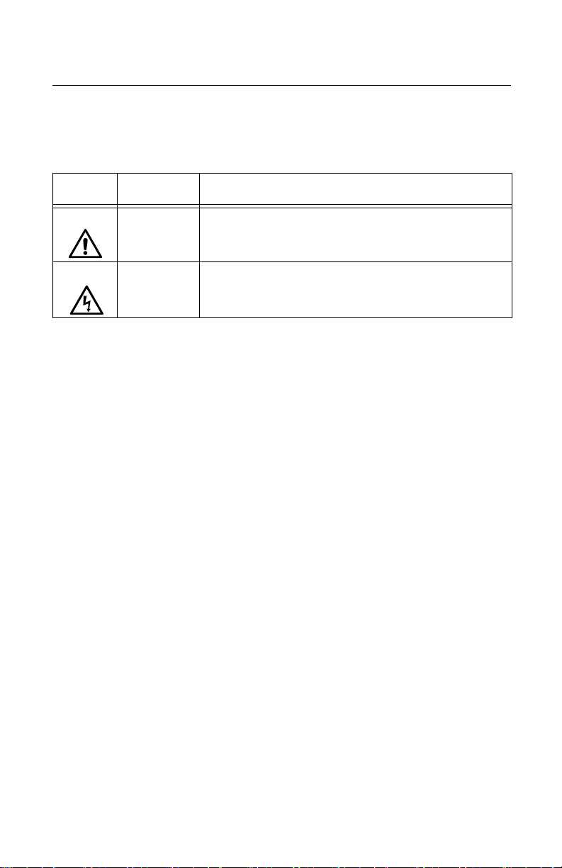
Table 1. Safety Symbols
Symbol Meaning Description
Caution Performing or omitting a specific action may result in
equipment damage or loss of data.
Warning Performing or omitting a specific action may result in
electrical shock.
12
Page 13

AT-MCF2000M Management Module Installation Guide
Where to Find Web-based Guides
The installation and user guides for all Allied Telesis
products are available in portable document format (PDF)
from our web site at www.alliedtelesis.com. You can view
the documents online or download them onto a local
workstation or server.
13
Page 14

Preface
Contacting Allied Telesis
This section provides Allied Telesis contact information for
technical support as well as sales and corporate
information.
Online
Support
Email and
Telephone
Support
You can request technical support online by accessing the
Allied Telesis Knowledge Base: www.alliedtelesis.com/
support. You can use the Knowledge Base to submit
questions to our technical support staff and review answers
to previously asked questions.
For Technical Support via email or telephone, refer to the
Support section of the Allied Telesis web site:
www.alliedtelesis.com.
Warranty The AT-MCF2000M Management Module has a 5 Year
Warranty. All Allied Telesis warranties are subject to the
terms and conditions set out in the Allied Telesis Limited
Warranties on our web site at www.alliedtelesis.com/
warranty.
Returning
Products
Products for return or repair must first be assigned a return
materials authorization (RMA) number. A product sent to
Allied Telesis without an RMA number will be returned to
the sender at the sender’s expense.
To obtain an RMA number, go to the Support section on our
web site at www.alliedtelesis.com/support/rma. Select
your country from the list displayed on the website. Then
select the appropriate menu tab.
Sales or
Corporate
Information
Management
Software
Updates
14
You can contact Allied Telesis for sales or corporate
information through our web site at
www.alliedtelesis.com.
New releases of the management software for our
managed products are available from the following Internet
sites:
Allied Telesis web site: www.alliedtelesis.com
Allied Telesis FTP server:
ftp://ftp.alliedtelesis.com
Page 15

AT-MCF2000M Management Module Installation Guide
If the FTP server prompts you to log on, enter “anonymous”
as the user name and your email address as the password.
15
Page 16

Preface
16
Page 17

Chapter 1
Overview
This chapter contains the following sections:
“Features” on page 18
“Front Panel” on page 20
“10/100/1000Base-T Management Port” on page 21
“RS-232 Terminal Port” on page 23
“Stack Port” on page 24
“Reset Button” on page 29
“SD Slot” on page 31
“Chassis ID Jumper” on page 32
“Module LEDs” on page 33
17
Page 18
Chapter 1: Overview
Features
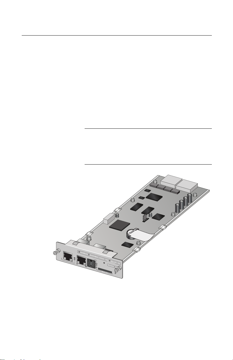
The AT-MCF2000M unit is a management module for the
media converter modules and chassis in the AT-MCF2000
Media Converter Series. With its preinstalled AT-S97
Management Software, this management device provides
complete control over the operating parameters of the ports
and channels on the AT-MCF2000 Media Converter Series.
Management is supported both locally (out-of band) through
the RS-232 Terminal port on the module and remotely over
a network (in-band) through the 10/100/1000Base-T
Ethernet port. Also featured is a stacking port for managing
multiple media converter devices as a single unit.
Note
The AT-MCF2000M Management Module is optional
equipment for the AT-MCF2000 Media Converter
Series. The AT-MCF2000 media converter modules
can operate as unmanaged devices.
AT-MCF2000M
ST
A
C
K
L
IN
K
AC
T
M
A
N
AG
E
M
10
E
N
00
T
L
INK
AC
T
10/1
T
0
E
0 L
R
M
IN
IN
KAC
A
L
T
F
P
D
O
X
R
T
H
A
D
C
X
T
IV
IT
C
Y
O
L
1
0
/1
0
0
/
1
0
0
0
B
A
S
E
-T
R
E
S
E
T
BOO
T
R
D
Y
FA
U
L
RS-232
T
SD
R
D
Y
B
USY
1198a
M
A
S
T
E
R
POW
E
R
Figure 1. AT-MCF2000M Management Module
18
Page 19

AT-MCF2000M Management Module Installation Guide
Here are some of the management functions you can
perform with the module and the AT-S97 Management
Software:
Configure the operating parameters of the twisted pair
ports in the media converter channels:
– Auto-Negotiation
– Speed
– Duplex mode
– MDI/MDI-X configuration
Set the duplex mode of the fiber optic ports.
Select the operating mode of a media converter
channel:
– MissingLink
™
– Smart MissingLink
– Link Test
Establish rate limits for the ingress and egress packets
on the ports of the media converter channels.
Reset media converter modules.
View event messages.
Send event messages to a syslog server.
Manage up to sixty-four media converter modules from
one management module.
Create additional manager accounts.
Download new versions of the management software to
the management and media converter modules.
Note
For a complete list of the management features, refer
to the AT- S85 and AT-S97 Management Software
Command Line User’s Guide, available from the Allied
Telesis web site.
19
Page 20
Chapter 1: Overview
Front Panel
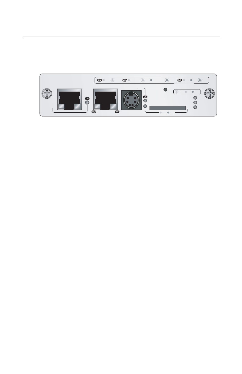
Figure 2 illustrates the front panel of the AT-MCF2000M
Management Module.
AT-MCF2000M
STACK MANAGEMENT
LINK ACT
10/100/1000BASE-T
1000 LINK ACT 10/100 LINK ACT FDX HDX COL
TERMINAL
RS-232
RESET
RDY
SD
BUSY
PORT ACTIVITY
RDY
BOOT
FAULT
MASTER
POWER
1199
Figure 2. Front Panel of the AT-MCF2000M Management
Module
The components of the panel are mentioned here:
Stack port - Multiple media converter devices can be
managed as a single unit through this port. For further
information, refer to “Stack Port” on page 24.
10/100/1000Base-T Management Port - This standard
Ethernet, Fast Ethernet, and Gigabit Ethernet port adds
support for management functions that require access
to a network, such as remote (in-band) management
from a Telnet or Secure Shell (SSH) client and
downloading or uploading files to a TFTP server. For
further information, refer to “10/100/1000Base-T
Management Port” on page 21.
RS-232 Terminal port - Local (out-of-band) management
of the chassis or stack is performed through this port
with a console or a PC with a terminal emulation
program. For further information, refer to “RS-232
Terminal Port” on page 23.
Reset button - This button performs a soft reset of the
module by initializing the AT-S97 Management
Software. For further information, refer to “Reset Button”
on page 29.
SD slot - This slot can accommodate a secure digital
memory card for storing configuration files or
transferring files between management modules. For
further information, refer to “SD Slot” on page 31.
20
Page 21

AT-MCF2000M Management Module Installation Guide
10/100/1000Base-T Management Port
The 10/100/1000Base-T Management port is a standard
Ethernet, Fast Ethernet, and Gigabit Ethernet port. The
module communicates with your network through this port
when it performs any of the management functions that
require a network connection. (Although the management
module can configure the operating parameters of the
media converter modules in a chassis, it cannot transmit or
receive management packets through the ports in the
media converter channels.)
This port must be connected to a device on your network,
such as a Fast Ethernet or Gigabit Ethernet switch, if the
module will be performing any of the following management
functions:
Remote management using the Telnet or Secure Shell
(SSH) application protocol
Upload or download files to its file system using a TFTP
server.
Set its date and time from a Network Time Protocol
(NTP) server.
Send events to a syslog server.
Obtain an IP configuration from a DHCP or BOOTP
server.
Send or receive TCP/IP ping requests from network
devices.
Send Simple Network Management Protocol (SNMP)
traps to an SNMP management program.
The port can operate at 10, 100, or 1000 Mbps in either
half- or full-duplex mode. The port has a standard RJ-45
8-pin connector and uses TIA/EIA 568-B-compliant
Category 3 or better cable for 10 Mbps operation and TIA/
EIA 568-B-compliant Enhanced Category 5 (Cat 5e) cable
for 100 or 1000 Mbps operation. The port has a maximum
operating distance of 100 meters. For port pinouts, refer to
“10/100/1000Base-T Management Port Pinouts” on
page 68.
21
Page 22

Chapter 1: Overview
IEEE 802.3u compliant, the port can set its speed and
duplex mode automatically with Auto-Negotiation, the
default setting. Auto-Negotiation can be disabled and the
speed and duplex mode set manually with the AT-S97
Management Software.
The wiring configuration of the port is set automatically with
auto-MDI/MDI-X to either MDI or MDI-X, depending on the
wiring configuration of the end node. This permits the use of
a straight-through twisted pair cable regardless of the wiring
configuration of the port on the network device.
The auto-MDI/MDI-X feature is only available when the port
is using Auto-Negotiation. If Auto-Negotiation is disabled
and the port’s speed and duplex mode are set manually,
this feature is disabled and the port defaults to the MDI-X
setting. Depending on the wiring configuration of port on the
remote device, you may need to manually configure the
MDI/MDI-X setting on the 10/100/1000Base-T Terminal port
or use a crossover cable.
22
Page 23

RS-232 Terminal Port
The management module can be managed locally through
this port with a console or a PC with a terminal emulation
program. This type of management method is referred to as
local or out-of-band management because it is not
conducted over a network.
The module comes with an RS-232 Serial Management
cable for this type of management. For instructions on how
to start a local session, refer to “Starting a Local
Management Session” on page 56 or the AT-S85 and
AT-S97 Management Software Command Line User’s
Guide.
The management module does not need an Internet
Protocol (IP) address for local management.
AT-MCF2000M Management Module Installation Guide
23
Page 24

Chapter 1: Overview
Stack Port
You can simplify the management of two or more
AT-MCF2000 chassis by interconnecting the devices with
the Stack port and managing them as a single unit. Some of
the benefits of the Stack port and the stacking feature are:
A stack requires only one AT-MCF2000M Management
Module.
A stack can consist of up to eight AT-MCF2000 Multi-
channel Media Converter Chassis and 16 media
converter modules.
A stack requires only one IP configuration.
You can add or remove a chassis from the stack without
interrupting the flow of network traffic through the
channels on the media converter modules.
Stack with a
Single
Management
Module
A stack must have one AT-MCF2000M Management
Module. The module must be installed in a chassis at one
end of the stack. The other units are connected to the stack
with the AT-MCF2000S Stacking Module, which has two
stacking ports.
The media converter units are connected together in a
daisy chain topology using the Stack ports. The Stack port
on the AT-MCF2000M Management Module must be
connected to a Stack port on the AT-MCF2000S Stacking
Module in the next chassis, which must be connected to a
Stack port in the next chassis, and so on. The topology
does not support redundant connections or loops.
24
Page 25

AT-MCF2000M Management Module Installation Guide
An example of a stack with four media converter chassis is
illustrated in Figure 3.
Unit with the
AT-MCF2000M
Management
Module
Units with the
AT-MCF2000S
Stacking
Module
Figure 3. Example Stack of Four Media Converter Chassis
The Stack port on the management module and the
stacking module use standard straight-through or crossover
TIA/EIA 568-B-compliant Enhanced Category 5 (Cat 5e)
shielded or unshielded cabling with 100 ohm impedance.
The maximum length of a cable is 100 meters, as shown in
Figure 4. This makes it possible to create a stack of devices
in different racks or even different wiring closets.
100 meters
maximum
Figure 4. Maximum Stacking Cable Length
To manage a stack, you must start your local and remote
management sessions on the management module. For
local management, you connect a terminal or a personal
computer with a terminal emulation program to the RS-232
Terminal port on the management module. For remote
management, such as with the Telnet application protocol,
you assign the management module an IP configuration
and access the module from your remote workstation using
the module’s IP address.
25
Page 26

Chapter 1: Overview
A chassis with the AT-MCF2000S Stacking Module must be
managed through the stack because the module does not
have a port for a local connection.
Note
The traffic on the Stack ports on the AT-MCF2000M
and AT-MCF2000S Modules is limited to management
packets from the management and stacking modules.
These ports do not carry media converter traffic.
A media converter channel in a chassis of a stack
operates as an independent entity. Its network traffic is
restricted to that channel and cannot crossover to
another media converter channel in the same chassis
or stack.
Maximum
Number of
Media
Converter
Modules
Chassis ID
Numbers
A stack can have up to 16 media converter modules. Since
the maximum size of a stack is determined not by the
number of chassis but by the number of media converter
modules, you must count the number of slots in the units of
the proposed stack before cabling the stacking ports. If the
number of slots exceed 16 units, you must divide the units
into more than one stack.
For example, a stack made up exclusively of the
AT-MCF2000 chassis, which has two media converter slots
per unit, can have up to 16 media converter modules:
8 chassis x 2 slots =16 media converter modules
Note
The AT-MCF2000 chassis was the only chassis model
available when this manual was published. For
information on the availability of other chassis models
in the AT-MCF2000 Media Converter Series, contact
your Allied Telesis sales representative.
Each chassis in a stack must have a unique chassis ID
number from 0 to 31. The AT-S97 Management Software
uses the chassis ID numbers to identify the different
devices in a stack.
You set the chassis ID numbers on the AT-MCF2000M and
AT-MCF2000S modules. The chassis ID number for the
AT-MCF2000M Management Module, set with a jumper on
the circuit board, can be either 0 or 31. The default value of
26
Page 27

AT-MCF2000M Management Module Installation Guide
the management module is 0. The ID number for the
AT-MCF2000S Stacking Module is set with DIP switches
and can range from 1 to 30. The default value of the
stacking module is 1.
Before you install the management and stacking modules in
a chassis, you must set the chassis ID numbers. The
jumper and DIP switches are not accessible after the
installation of the modules. In addition, the ID numbers
cannot be controlled through the AT-S97 Management
Software.
The ID numbers assigned to the devices in a stack do not
need to be sequential or reflect a devices’ position relative
to the chassis with the management module. However, the
chassis ID number must be unique within the stack.
The range of the chassis ID numbers is unrelated to the
maximum number of chassis permitted in a stack. As
explained in the previous section, “Maximum Number of
Media Converter Modules” on page 26, the maximum
number of devices in a stack is determined by the number
of media converter modules, with a maximum of 16
modules.
Connecting
and
Disconnecting
Stacking
Cables
Guidelines to
Building a
Stack
Assign the master management module’s a chassis ID
number of 0. For further information, refer to the AT-S85
and AT-S97 Management Software Command Line
Interface User’s Guide.
The packet traffic on the Stack ports on the AT-MCF2000M
Management Module and the AT-MCF2000S Stacking
Module is restricted to management traffic between the
management and stacking modules. These ports do not
carry traffic from the media converter channels.
Consequently, the operations of the media converter
channels in the units are not affected when cables are
connected or disconnected from the Stack ports on the
management and stacking modules.
The following guidelines apply to building a stack of
AT-MCF2000 chassis:
A stack can have up to eight chassis and 16 media
converter modules.
The maximum distance between two Stack ports is 100
meters (328 feet).
27
Page 28

Chapter 1: Overview
The chassis with the AT-MCF2000M Management
Module must be at one end of the stack.
The other units are connected to the stack with the
AT-MCF2000S Stacking Module.
Each chassis must be assigned a unique chassis ID
number from 0 to 31. The ID number for the
AT-MCF2000M Management Module can be 0 or 31.
The range of the ID number for the AT-MCF2000S
Stacking Module is from 1 to 30. The AT-MCF2000M
Management Module has a jumper for setting the
number and the AT-MCF2000S Stacking Module has
DIP switches.
The ID numbers to the chassis of a stack do not have to
be sequential and they do not have to reflect the
numerical position of a chassis in the daisy chain
topology, relative to the chassis with the management
module.
The stacking feature does not require an IP
configuration on the management module.
A chassis with the AT-MCF2000S Stacking Module must
be managed through the stack because the module
does not have a port for local management.
There cannot be an intermediary network device, such
as a router or Ethernet switch, between two Stack ports.
The units in a stack function as independent media
converters. The traffic of a media converter channel on
a module is restricted to its channel and cannot
crossover to another channel in the same chassis or
another unit in the stack.
Since the stacking cables carry only management traffic
between the management module and the stacking
modules, the cables connected to the Stack ports can
be disconnected and reconnected at any time without
interrupting the flow of network traffic through the
channels on the media converter modules.
28
Page 29

Reset Button
AT-MCF2000M Management Module Installation Guide
The Reset button on the front panel of the management
module initializes the AT-S97 Management Software and
the active master configuration file. Situations where
resetting the module might be necessary include the
following:
To reconfigure the modules in the chassis or stack after
selecting a new active master configuration file. For
background information, refer to the AT- S85 and
AT-S97 Management Software Command Line User’s
Guide.
If the management module is experiencing a problem.
Note
The management module takes about one minute to
initialize the AT-S97 Management Software and is
unresponsive to management commands during the
initialization process. You can determine when the
module has completed the initialization process by
viewing the general status LEDs on the module. For
information, refer to “General Status LEDs” on
page 33.
Note
Changes to the parameter settings of the
management module (for example, IP configuration,
name, Telnet server status, etc.) that have not been
saved to the active master configuration file are
discarded when you reset the management module.
To save your changes, establish a local or remote
management session with the management module
and issue the BOOT CONFIG-FILE SAVE command.
For more information, refer to the AT- S 85 and AT-S97
Management Software Command Line User’s Guide.
To prevent someone from accidentally resetting the
management module, the Reset button is recessed in the
module. Pressing the button requires a pointed object, such
as the tip of a pen, as shown in Figure 5 on page 30, or the
end of a straightened paper clip.
29
Page 30

Chapter 1: Overview
AT-MCF2000M
STACK MANAGEMENT
LINK ACT
1000 LINK
ACT 10/100 LINK ACT
10/100/1000BAS
TERMINAL
E-T
RS-232
FDX
PO
R
T A
HDX COL
CTIVITY
RESET
B
OOT
R
DY
FAULT
SD
MASTER
R
DY BU
S
Y
POWER
Figure 5. Pressing the Reset Button
AT-MCF2KFAN
1203b
STATUS
NO
FA
R
M
A
L
U
LT
30
Page 31

SD Slot
AT-MCF2000M Management Module Installation Guide
The SD slot accommodates a secure digital memory card.
You might use a memory card in the following situations:
Storing backup copies of the configuration files from the
management and media converter modules - You can
maintain a library of past configuration files in the event
a module needs to be returned to a previous
configuration.
Transferring configuration files between chassis - You
can simplify the task of configuring units that are to have
similar configurations by configuring one of the units and
transferring its configuration files to the other units with a
secure digital memory card.
A secure digital memory card is optional. The management
module can operate without a memory card.
For information on using a secure digital memory card with
the management module, refer to the AT-S85 and AT-S97
Management Software Command Line Interface User’s
Guide.
Note
The management module supports 128 MB, 256 MB,
and 512 MB secure digital memory cards. Memory
cards are available from Allied Telesis. For ordering
information, contact your Allied Telesis sales
representative or visit our web site.
Note
Do not remove a secure digital memory card from the
management module when the slot’s L/A LED is
amber. Wait for the LED to change to green before
removing the card.
31
Page 32

Chapter 1: Overview
Chassis ID Jumper
The module has a jumper on the circuit board for setting the
ID number of the module’s chassis. Refer to Figure 6. The
chassis ID number for the AT-MCF2000M Management
Module can be 0 or 31. The default setting is 0. For
background information, refer to “Chassis ID Numbers” on
page 26.
For instructions on setting the jumper, refer to “Setting the
Chassis ID Jumper” on page 45.
AT-MCF2000M
S
T
A
C
K
L
IN
K
M
A
N
AG
E
M
E
N
T
1
0
/1
0
0
/
1
0
0
0
B
A
S
E
-T
Chassis ID
Jumper
AC
T
100
0 L
INK
AC
T 10/1
T
0
E
0 L
R
M
IN
IN
KAC
A
L
T
F
P
D
O
X
R
T
H
A
D
C
X
T
IV
IT
C
Y
O
L
R
E
S
E
T
BOO
T
R
D
Y
FA
U
L
RS-232
T
SD
M
R
D
A
Y
S
T
E
R
B
USY
POW
E
R
Figure 6. Chassis ID Jumper
Note
You cannot change the chassis ID number with the
AT-S97 Management Software.
32
Page 33

Module LEDs
AT-MCF2000M Management Module Installation Guide
The section describes the LEDs on the management
module.
General
Status LEDs
LED State Description
(unlabeled) Steady
The three LEDs on the left side of the panel provide general
information on the status of the management module. One
LED is unlabeled. The other LEDs are Master and Power.
INK ACT
MENT
BASE-T
1000 LINK ACT 10/100 LINK ACT FDX HDX COL
TERMINAL
RS-232
RESET
SD
RDY
PORT ACTIVITY
BOOT
BUSY
RDY
FAULT
MASTER
POWER
1199a
General Status
LEDs
Figure 7. General Status LEDs
Table 2 defines the states of the general status LEDs.
Table 2. General Status LEDs
The management module is operating
green
normally.
Flashing
Green
The management module is initializing the
AT-S97 Management Software and
loading its active master configuration file.
Red The management module has experienced
a fault condition.
Flashing
Red
The management module is receiving a
new version of the AT-S85 or AT-S97
Management Software. The destination of
the download can be the management
module or a media converter module.
33
Page 34

Chapter 1: Overview
0
LED State Description
Master Off This state is designated for future use.
Power Off The management module is not receiving
Table 2. General Status LEDs (Continued)
Green The module is functioning as the master
management module of the stack.
power or the power is not within the
permitted operating range.
Green The management module is receiving
power.
RS-232
Terminal
Port LED
The RS-232 Terminal port, used for local management of
the chassis or stack, has a L/A (Link/Activity) LED.
INK ACT
MENT
BASE-T
1000 LINK ACT 10/100 LINK ACT FDX HDX COL
TERMINAL
RS-232
RESET
RDY
SD
BUSY
PORT ACTIVITY
RDY
BOOT
FAULT
MASTER
POWER
1199a
RS-232 Terminal
Port LED
Figure 8. Link/Activity LED on the RS-232 Terminal Port
Table 3 defines the states of the LED.
Table 3. Link/Activity LED on the RS-232 Terminal Port
State Description
Off This LED setting is reserved for future use.
Green The management module has established
a link to the console connected to the port.
Flashing
Green
The management module is sending or
receiving data from the console connected
to the port.
34
Page 35

AT-MCF2000M Management Module Installation Guide
C
10/100/
1000Base-T
Management
Port LEDs
The 10/100/1000Base-T Management port has a L/A (Link/
Activity) LED and a D/C (Duplex-mode/Collisions) LED.
AT-MCF2000M
STACK MANAGEMENT
Link/Activity
10/100/1000BASE-T
LED
LINK ACT
1199b
Duplex-mode/
Collisions LED
1000 LINK A
TERMINAL
RS-232
Figure 9. Link/Activity and Duplex-mode LEDs on the
Management Port
The states of the Link/Activity LED are defined in Table 4.
Table 4. Link/Activity LED on the Management Port
State Description
Off The port has not established a link with a
network device.
Steady
Green
Flashing
Green
Steady
Amber
Flashing
Amber
The port has established an 1000 Mbps
link with a network device, but is not
forwarding or receiving network packets.
The port has established an 1000 Mbps
link with a network device and is
forwarding or receiving network packets.
The port has established a 10 or 100 Mbps
link with a network device, but is not
forwarding or receiving network packets.
The port has established a 10 or 100 Mbps
link with a network device and is
forwarding or receiving network packets.
35
Page 36

Chapter 1: Overview
K
The states of the Duplex-mode/Collisions LED on the
Management port are described in Table 5.
Table 5. Duplex-mode/Collisions LED on the Management
Port
State Description
Stack Port
LED
Steady
The port is operating in full-duplex mode.
Green
Steady
The port is operating in half-duplex mode.
Amber
Flashing
Amber
The port is operating in half-duplex mode
with collisions.
The L/A (Link/Activity) LED on the Stack port is shown in
Figure 10.
AT-MCF2000M
STACK MANAGEMENT
LINK ACT
10/100/1000BASE-T
1000 LIN
TERMINAL
RS-232
1199b
Link/Activity LED
Figure 10. Link/Activity LED on the Stack Port
The states of the Link/Activity LED are defined in Table 6.
Table 6. Link/Activity LED on the Management Port
State Description
Off The chassis is not part of a stack or the
port has not established a link with the
Stack port in the next chassis.
Steady
Green
36
The port has established a link with the
Stack port in the next chassis in the stack.
Page 37

AT-MCF2000M Management Module Installation Guide
Table 6. Link/Activity LED on the Management Port
State Description
Secure Digital
Memory
Card Slot
LED
Flashing
Green
The port is forwarding or receiving
management packets from the next
chassis in the stack.
The secure digital memory card slot has one LED.
INK ACT
MENT
BASE-T
1000 LINK ACT 10/100 LINK ACT FDX HDX COL
TERMINAL
RS-232
RESET
SD
RDY
PORT ACTIVITY
BOOT
BUSY
RDY
FAULT
MASTER
POWER
1199a
SD Slot LED
Figure 11. SD Slot LED
The states of the LED are defined in Table 7.
Table 7. SD Slot LED
State Description
Off The SD slot is empty or a card is installed
improperly.
Green A secure digital memory card is present in
the slot.
Amber The management module is retrieving or
storing data on a secure digital memory
card.
Note
Do not remove a secure digital memory card from the
SD slot when the LED is amber. Wait for the LED to
change to green before removing the card.
37
Page 38

Chapter 1: Overview
38
Page 39

Chapter 2
Installation
This chapter contains the following sections:
“Reviewing Safety Precautions” on page 40
“Cable Requirements” on page 42
“Unpacking the AT-MCF2000M Management Module”
on page 44
“Setting the Chassis ID Jumper” on page 45
“Installing the Management Module” on page 47
“Cabling a Media Converter Stack” on page 52
“Verifying the Installation” on page 55
“Starting a Local Management Session” on page 56
“Removing the AT-MCF2000M Management Module”
on page 59
“Installing a Media Converter Module” on page 61
For instructions on how to install the chassis, refer to the
chassis’ Installation Guide.
39
Page 40

Chapter 2: Installation
Reviewing Safety Precautions
Please review the following safety precautions before you
begin to install the management module.
Note
The indicates that a translation of the safety
statement is available in a PDF document titled
“Translated Safety Statements” (613-000990) posted
on the Allied Telesis website at www.alliedtelesis.com.
This document is also included with the
documentation CD that is shipped with the product.
Warning: Do not work on equipment or cables
during periods of lightning activity.
Warning: Electrical-Type Class 1 Equipment:
This equipment must be earthed. The power
plug must be connected to a properly wired earth
ground socket outlet. An improperly wired socket
outlet could place hazardous voltages on
accessible metal parts. E4
E2
Pluggable Equipment. The socket outlet shall be
installed near the equipment and shall be easily
E5
E6
E8
accessible.
Caution: Air vents must not be blocked and
must have free access to the room ambient air
for cooling.
Warning: Operating Temperature. This product
is designed for a maximum ambient temperature
of 40° degrees C. E7
All Countries: Install product in accordance with
local and National Electrical Codes.
40
Page 41

AT-MCF2000M Management Module Installation Guide
Warning: Only trained and qualified personnel
are allowed to install or to replace this
equipment.
Caution: Do not install in direct sunlight, or a
damp or dusty place.
Caution: Do not expose the device to moisture
or water. E17
Warning: Mounting of the equipment in the rack
should be such that a hazardous condition is not
created due to uneven mechanical loading.
E25
Caution: Installation of the equipment in a rack
should be such that the amount of air flow
required for safe operation of the equipment is
not compromised.
E14
E36
E16
Warning: Risk of explosion if battery is replaced
by an incorrect type. Replace only with the same
or equivalent type recommended by the
manufacturer. Dispose of used batteries
according to the manufacturer’s instructions.
Attention: Le remplacement de la batterie par
une batterie de type incorrect peut provoquer un
danger d’explosion. La remplacer uniquement
par une batterie du même type ou de type
équivalent recommandée par le constructeur.
Les batteries doivent être éliminées
conformément aux instructions du constructeur.
E22
41
Page 42

Chapter 2: Installation
Cable Requirements
10/100/
1000Base-T
Management
Port
Table 8 lists the cable requirements for the 10/100/
1000Base-T Management port. For background
information, refer to “10/100/1000Base-T Management
Port” on page 21. For port pinouts, refer to “10/100/
1000Base-T Management Port Pinouts” on page 68.
Table 8. Cable Requirements for the 10/100/1000Base-T
Management Port
Maximum
Speed Cable Type
10 Mbps Standard TIA/EIA 568-B-
compliant Category 3 or
better shielded or
unshielded cabling with
100 ohm impedance and
a frequency of 16 MHz.
100 or
1000 Mbps
Standard TIA/EIA 568-Bcompliant Enhanced
Category 5 (Cat 5e)
shielded or unshielded
cabling with 100 ohm
impedance and a
frequency of 100 MHz.
Operating
Distance
100 m (328 ft)
100 m (328 ft)
Note
The default setting for the Management port is AutoNegotiation with auto-MDI/MDI-X. In the default
setting, the port’s speed, duplex mode, and
MDI/MDI-X settings are set automatically.
42
Page 43

AT-MCF2000M Management Module Installation Guide
Stack Port Table 9 lists the cable requirements for the Stack port. For
background information, refer to “Stack Port” on page 24.
Table 9. Cable Requirements for the Stack Port
Maximum
Cable Type
Operating
Distance
Standard straightthrough or crossover TIA/
EIA 568-B-compliant
Enhanced Category 5
(Cat 5e) shielded or
unshielded cabling with
100 ohm impedance.
100 m (328 ft)
43
Page 44

Chapter 2: Installation
Unpacking the AT-MCF2000M Management Module
To unpack the module, perform the following procedure:
1. Remove all components from the shipping package.
Note
Store the packaging material in a safe location. You
must use the original shipping material if you need to
return the unit to Allied Telesis.
2. Verify that the following items are included in the
shipping package. If an item is missing or damaged,
contact your Allied Telesis sales representative for
assistance.
One AT-MCF2000M Management Module
One RS-232 Serial Management Cable with DIN-8
and DB-9 connectors for local management
This installation guide
44
Page 45

AT-MCF2000M Management Module Installation Guide
Setting the Chassis ID Jumper
The management module has a jumper on the circuit board
for setting the chassis ID. The AT-MCF2000M Management
Module can have a chassis ID value of 0, the default
setting, or 31.
You can leave the jumper in the default setting if the media
converter chassis will not be part of a stack or for a stack
that has just one management module.
For a stack with two AT-MCF2000M Management Modules,
you must change the chassis ID of one management
module to 31 because two management modules in the
same stack must have different chassis ID numbers.
Refer to Figure 12 or the legend printed next to the jumper
for the supported settings.
AT-MCF2000M
ST
A
CK M
Chassis ID Jumper
LINK ACT
AN
AGEMEN
1000 LIN
T
K
ACT 10/100 LIN
TERM
INAL
KACT
FDX
PO
R
T A
HDX COL
CTIVITY
1
0
/1
0
0
/
1
0
0
0
B
A
S
E
-T
RE
SET
B
O
O
T
R
D
Y
FA
U
L
RS-
232
T
SD
MASTER
R
D
Y
B
U
S
Y
POW
ER
Chassis ID 0
Chassis ID 31
(Default)
Figure 12. Setting the Chassis ID Jumper
For further information on chassis ID numbers, refer to
“Chassis ID Numbers” on page 26 or the AT-S85 and
AT-S97 Management Software Command Line Interface
User’s Guide.
45
Page 46

Chapter 2: Installation
Caution
The management module is sensitive to and can be
damaged by electrostatic discharge. Wear a
grounding device and observe electrostatic discharge
precautions when setting the chassis ID jumper.
Note
You cannot set the chassis ID number with the AT-S97
Management Software.
46
Page 47

AT-MCF2000M Management Module Installation Guide
Installing the Management Module
Caution
The management module is sensitive to and can be
damaged by electrostatic discharge. Wear a
grounding device and observe electrostatic discharge
precautions when installing a management module in
the chassis.
Note
The AT-MCF2000M Management Module supports
hot swapping. You can install the module while the
chassis is powered on.
Note
This procedure uses the AT-MCF2000 chassis for
illustration purposes. Your chassis may be different.
To install the management module in the chassis, perform
the following procedure:
1. Using a cross-head screwdriver, loosen the two captive
screws that secure the blank panel over the
management slot and remove the panel from the
chassis, as shown in Figure 13 on page 48. Refer to
the chassis’ Installation Guide for the location of the
management slot.
Note
Do not remove the blank panel from the chassis until
you are ready to install a module. An open slot allows
dust to enter the unit and interferes with the chassis’
ability to maintain proper airflow and cooling.
47
Page 48

Chapter 2: Installation
N
S
AT-MCF2000M
ST
A
CK MANAGEMENT
AT-MCF2KPNL3
Figure 13. Removing the Blank Panel from the
Management Slot
2. Remove the insulator labelled “REMOVE BEFORE
INSTALL” from the battery on the management module
by sliding it out from beneath the battery clip. Refer to
Figure 14.
Battery
Insulator
LINK
ACT
1000 LIN
K
ACT 10/10
TERMINAL
0 LINK ACT
FDX
P
O
R
T
A
HDX COL
C
TIV
IT
Y
10/100/1000
B
ASE-T
RESET
BOO
T
R
D
Y
FA
U
L
RS-232
T
SD
R
D
Y
B
USY
MASTER
POWER
1198a
AT-MC F2KFA
STATU
NO
R
M
A
FA
U
LT
Figure 14. Removing the Battery Insulator
48
Page 49

AT-MCF2000M Management Module Installation Guide
N
L
S
A
T
-M
C
F2000M
S
TA
C
K
M
A
N
AG
E
M
E
N
T
T
E
R
M
IN
A
L
1
0
/1
0
0
/1
0
0
0
B
A
S
E
T
R
S
-2
3
2
R
E
S
E
T
S
D
R
D
Y
B
U
S
Y
M
A
S
T
E
R
P
O
W
E
R
B
O
O
T
R
D
Y
F
A
U
L
T
1
0
0
0
L
IN
K
A
C
T
1
0
/1
0
0
L
IN
K
A
C
T
F
D
X
H
D
X
C
O
L
L
IN
K
A
C
T
PO
R
T
A
CTIVITY
3. Align the edges of the module with the guides in the
slot and carefully slide the module into the chassis until
it is flush with the front of the chassis. Refer to Figure
15. Light pressure may be necessary to firmly seat the
module connector on the connector on the back panel
of the chassis.
Caution
Do not force the module into place. Doing so may
damage the connector pins on the backplane of the
chassis. If there is resistance, remove the module and
reinsert it after verifying that the edges of the card are
properly aligned in the guides in the chassis’ module
slot.
AT-MCF2KFA
STA
TU
NORMA
FAULT
1200a
Figure 15. Installing the Management Module
49
Page 50

Chapter 2: Installation
AT-MCF2000M
STACK MANAG
EME
NT
TER
M
INAL
10/100/1000BASE-T
R
S
2
32
RESET
S
D
R
DY BU
S
Y
MASTER
POW
ER
B
O
OT
R
DY
FAU
LT
10
00 L
INK
AC
T 10/100
L
IN
K
ACT
FDX
HD
X
C
O
L
LINK AC
T
PO
R
T A
CTIVITY
4. Secure the management module to the chassis by
tightening the two captive screws on the module with a
cross-head screwdriver. Refer to Figure 16.
AT-MCF2KFAN
1201a
Figure 16. Securing the Management Module
5. Connect a standard TIA/EIA 568-B-compliant
Enhanced Category 5 (Cat 5e) shielded or unshielded
cable to the 10/100/1000Base-T Management port.
Refer to Figure 17. Connect the other end of the cable
to a network device, such as a Fast Ethernet or Gigabit
Ethernet switch.
STATUS
NORMAL
FAULT
50
You can skip this step if the management module will
not require access to your network. For background
information, refer to “10/100/1000Base-T Management
Port” on page 21.
AT-MCF2000M
STACKMAN
L
IN
K
AC
T
AG
EMENT
1000 LIN
K
AC
T 10/100
TER
LINK ACT
M
10/100/1000BASE-T
INAL
R
S
2
3
2
F
PO
D
X
R
T A
H
D
CTIVITY
X
C
O
L
RESET
B
O
OT
S
D
R
DY BU
S
Y
AT-MCF2KFAN
R
DY
FAULT
M
AS
TER
POW
ER
STATUS
NORMAL
FAULT
1202a
Figure 17. Connecting an Enhanced Category 5 Network
Cable to the 10/100/1000Base-T Management Port
Page 51

AT-MCF2000M Management Module Installation Guide
6. If the chassis will be part of a stack, Allied Telesis
recommends affixing a label with the chassis ID
number to the front of the unit. (Refer to “Setting the
Chassis ID Jumper” on page 45 for information on the
ID number.) The label should also include the chassis’
MAC address, found on the bottom panel of the device
or displayed with the AT-S97 Management Software.
Having this information on the front panel will make it
easier for you to identify the individual physical units of
the stack when you manage the media converters with
the management software.
This completes the initial installation of the AT-MCF2000M
Management Module. To complete the installation, do the
following:
To install additional modules in the chassis, refer to the
modules’ Installation Guide for instructions.
To create a stack of media converter units, refer to
“Cabling a Media Converter Stack” on page 52.
To verify the installation, refer to “Verifying the
Installation” on page 55.
To begin managing the chassis or stack, refer to
“Starting a Local Management Session” on page 56 or
the AT-S85 and AT-S97 Management Software
Command Line Interface User’s Guide.
51
Page 52

Chapter 2: Installation
Cabling a Media Converter Stack
To create a stack, connect the units together in a daisy
chain topology using the Stack ports on the AT-MCF2000M
and AT-MCF2000S modules. The Stack port on the
AT-MCF2000M Management Module must be connected to
the Stack 1 or Stack 2 port on the AT-MCF2000S Stacking
Module in the next chassis of the stack. The remaining
Stack port on the stacking module must be connected to
either the Stack 1 or Stack 2 port in the next chassis, and so
on. Loops are not supported. For cable specifications, refer
to “Cable Requirements” on page 42.
Note
Allied Telesis recommends reviewing the information
in “Guidelines to Building a Stack” on page 27 before
cabling the stack.
To cable a stack, perform the following procedure:
1. To connect a management module to a stacking
module, connect the management module’s Stack port
to either the Stack 1 or Stack 2 port on the stacking
module, as illustrated in Figure 18.
AT-MCF2000M Management
Module
AT-MCF2000M
STACK MANAGEMENT
10/100/1000BASE-T
1000 LINK ACT 10/100 LINK ACT FDX HDX COLLINK ACT
PORT ACTIVITY
TERMINAL
BOOT RDY FA ULT
RESET
MASTER
SD
RS-232
POWER
BUSY
RDY
AT-MCF2000S Stacking
Module
AT-MCF2000S
LINK ACT
STACK 1 STACK 2
PORT ACTIVITY
CHASSIS ID
OR
AT-MCF2000M
STACK MANAGEMENT
10/100/1000BASE-T
1000 LINK ACT 10/100 LINK ACT FDX HDX COLLINK ACT
PORT ACTIVITY
TERMINAL
BOOT RDY FAULT
RESET
MASTER
SD
RS-232
POWER
BUSY
RDY
AT-MCF2000S
LINK ACT
STACK 1 STACK 2
PORT ACTIVITY
CHASSIS ID
Figure 18. Cabling the AT-MCF2000M Management
Module to the AT-MCF2000S Stacking Module
52
Page 53

AT-MCF2000M Management Module Installation Guide
2. To connect two AT-MCF2000S Stacking Modules,
connect either the Stack 1 or Stack 2 port on the
stacking module to either the Stack 1 or Stack 2 port on
the stacking module in the next chassis of the stack. All
port combinations are supported, as illustrated in
Figure 19.
Repeat this step to connect the remaining
AT-MCF2000 media converter modules to the stack.
AT-MCF2000S
AT-MCF2000S
AT-MCF2000S
LINK ACT
STACK 1 STACK 2
PORT ACTIVITY
LINK ACT
STACK 1 STACK 2
PORT ACTIVITY
LINK ACT
STACK 1 STACK 2
PORT ACTIVITY
AT-MCF2000S
POWER
LINK ACT
STACK 1 STACK 2
PORT ACTIVITY
CHASSIS ID
OR
AT-MCF2000S
POWER
LINK ACT
STACK 1 STACK 2
PORT ACTIVITY
CHASSIS ID
OR
AT-MCF2000S
POWER
LINK ACT
STACK 1 STACK 2
PORT ACTIVITY
CHASSIS ID
OR
AT-MCF2000S
LINK ACT
STACK 1 STACK 2
PORT ACTIVITY
POWER
AT-MCF2000S
LINK ACT
STACK 1 STACK 2
PORT ACTIVITY
Figure 19. Cabling Two AT-MCF2000S Stacking Modules
CHASSIS ID
53
Page 54

Chapter 2: Installation
3. To connect the last chassis of a stack with just one
management module, you can use either port on the
AT-MCF2000S Stacking Module. The remaining port is
left unused.
54
Page 55

Verifying the Installation
This procedure verifies the installation of the
AT-MCF2000M Management Module. The procedure
assumes the chassis with the module is powered on.
To verify the installation of the module, perform the
following procedure:
1. Verify that the Power LED on the module is green.
2. If you connected a network cable to the 10/100/
1000Base-T Management Module, verify that the L/A
(Link/Activity) LED is green or amber.
3. If you connected a cable to the Stack port, the Link/
Activity LED for the port should be steady or flashing
green.
Note
If there are any problems, refer to Chapter 3,
“Troubleshooting” on page 63 for assistance.
AT-MCF2000M Management Module Installation Guide
55
Page 56

Chapter 2: Installation
Starting a Local Management Session
To start a local management session on the chassis or
stack, perform the following procedure:
1. Connect the DIN-8 connector on the RS-232
Serial Management cable included with the
AT-MCF2000M Management Module to the RS-232
Terminal port on the management module, as shown in
Figure 20.
AT-MCF2000M
STAC
K
L
IN
K
ACT
M
A
N
AG
E
M
1
E
N
T
T
E
R
M
10/100/1000BASE-T
R
S
-
000
L
IN
K
AC
T10
/100
LIN
IN
K
A
L
ACT
F
PO
D
X
R
T A
H
D
CTIV
X
ITY
C
O
L
R
E
S
E
T
2
3
2
BOOT
S
D
R
DY BUSY
AT-MCF2KFAN
R
DY
FAULT
M
A
S
T
E
R
POWE
R
STATUS
NORMAL
FAULT
1203a
Figure 20. Connecting the RS-232 Serial Management
Cable to the RS-232 Terminal Port
2. Connect the DB-9 connector on the RS-232 Serial
Management cable to an RS-232 port on a terminal or
PC with a terminal emulator program.
3. Configure the terminal or terminal emulation program
as follows:
Baud rate: 115200 bps (The baud rate of the
RS-232 Terminal port is adjustable from 9600 to
115200 bps. The default is 115200 bps. To adjust
the baud rate, refer to the AT-S85 and AT-S97
Management Software Command Line User’s
Guide.
Data bits: 8
Parity: None
Stop bits: 1
Flow control: None
56
Page 57

AT-MCF2000M Management Module Installation Guide
Note
The port settings are for a DEC VT100 or ANSI
terminal, or an equivalent terminal emulator program.
Note
The prompt “Hit any key to stop autoboot,” displayed
on the console when the management module is reset
or power cycled, is for manufacturing purposes only
and should be ignored. If you inadvertently display the
manufacturing prompt (=>), type “bootapp” to launch
the management software on the management
module.
4. Press Enter.
You are prompted for a user name and password.
5. Enter a user name and password of a manager
account on the management module.
The module comes with a predefined manager account
that permits access to all the parameters on the
management and media converter modules. The user
name of this account is “manager” and the default
password is “friend.” User names and passwords are
case sensitive.
The local management session starts and the
command line interface (CLI) prompt is displayed, as
shown in Figure 21.
Allied Telesis AT-MCF2000M - AT-S97
<No System Name>
#
Figure 21. CLI Prompt
6. To test the management module and the installation,
enter this command:
system show cluster
The command lists all the devices in the stack. If the
chassis with the management module is not part of a
stack, the command displays just the devices of that
57
Page 58

Chapter 2: Installation
chassis. For further information, refer to the AT-S85
and AT-S97 Management Software Command Line
Interface User’s Guide.
58
Page 59

AT-MCF2000M Management Module Installation Guide
Removing the AT-MCF2000M Management Module
The AT-MCF2000M Management Module supports hotswapping and can be removed from the unit when the
chassis is powered on. However, the replacement of a
management module may impact the operations of the
media converter modules in the chassis.
During normal operations, the media converter modules
obtain their parameter settings from the master
configuration file in the management module’s file system.
However, the media converter modules maintain auxiliary
configuration files in their own file systems that enable them
to retain their parameter settings even when a chassis is
without a management module. Consequently, the removal
of the management module will not affect the operations of
the media converter modules or the flow of network traffic
through the channel ports.
However, if you replace a management module, the
parameter settings in the master configuration file in the
new module may overwrite the settings on the media
converter modules. This may result in a disruption of the
flow of traffic through the channels on the media converter
modules.
For further information on auxiliary and master configuration
files, refer to the AT-S85 and AT-S97 Management
Software Command Line Interface User’s Guide.
To remove the AT-MCF2000M Management Module,
perform the following procedure:
1. Remove all cables from the ports on the module.
2. Using a cross-head screwdriver, loosen the two captive
screws that secure the module to the chassis.
3. Slide the module from the chassis.
Caution
The management module is sensitive to and can be
damaged by electrostatic discharge. Wear a
grounding device and observe electrostatic discharge
precautions when installing a management module in
the chassis.
59
Page 60

Chapter 2: Installation
4. If you are not replacing the module, reinstall the blank
panel over the management slot.
Note
Do not leave a chassis slot open. An open slot allows
dust to enter the chassis and reduces the airflow and
cooling of the components.
5. If you are replacing the module, begin the installation of
the new management module with “Unpacking the
AT-MCF2000M Management Module” on page 44.
Note
As previously mentioned, the replacement of a
management module may alter the parameter settings
of the media converter modules. For further
information, refer to the AT-S85 and AT-S97
Management Software Command Line Interface
User’s Guide.
60
Page 61

AT-MCF2000M Management Module Installation Guide
Installing a Media Converter Module
When a media converter module is installed into a chassis,
the AT-S97 Management Software on the management
module communicates with the module to determine the
appropriate operating parameters for the device. Some of
the variables that factor into the process include whether
the chassis slot had been used by another media converter
module and, if so, whether the new module is the same
model as the previous module. The goal is to reduce the
number of times you have to manually reconfigure the
modules when you install or replace devices in a chassis.
The possible scenarios and their outcomes are described
here:
A media converter module maintains its previous
parameter settings when removed and reinstalled in the
same chassis and slot.
A media converter module maintains its previous
settings (or uses the default settings if it is new) when
installed in a slot that has never been used before or
was previously used by a different media converter
model. For example, the AT-MCF2012LC Fast Ethernet
Media Converter Module, when installed in a slot
previously occupied by the AT-MCF2012LC/1 Fast
Ethernet Media Converter Module, maintains its prior
settings.
A media converter module that replaces a module of the
same model assumes the settings of the previous
module. For example, replacing the AT-MCF2012LC
module with another AT-MCF2012LC module causes
the new module to operate with the same settings as the
previous module.
More information on this subject can be found in the
discussions on configuration files in the AT-S85 and AT-S97
Management Software Command Line Interface User’s
Guide.
61
Page 62

Chapter 2: Installation
62
Page 63

Chapter 3
Troubleshooting
This chapter contains suggestions on how to troubleshoot
the AT-MCF2000M Management Module if a problem
occurs.
Problem 1: The Power LED on the module is off.
Solutions: Try the following:
Check the Status LED on the power supply module in
Check that the AT-MCF2000M Management Module is
Try replacing the module with another management
Problem 2: You are unable to start a local management
session on the management module.
the chassis. The LED should be steady green. If the
LED is off or signalling a fault condition, refer to the
chassis or power supply’s Installation Guide for
troubleshooting instructions.
fully inserted into the management slot in the chassis.
module.
Solutions: Try the following:
Verify that the RS-232 Serial Management Cable is
securely connected to the RS-232 Terminal port on the
module and to the port on the terminal or personal
computer.
Verify that the communications settings for the RS-232
port on the terminal or personal computer are set
correctly. For the appropriate settings, refer to “Starting
a Local Management Session” on page 56.
If the stack has two management modules, view the
Master LED on the module where you are trying to
start the management session. The LED should be
green, indicating that it is the master manager module
of the stack. If the LED is off, the module is in the
redundant state. You must start your local
management session on the other management
module in the stack.
63
Page 64

Chapter 3: Troubleshooting
Problem 3: A network cable is connected to the 10/100/
1000Base-T Management port, but the port’s Link/Activity
LED is off.
Solutions: Try the following:
Verify the network device connected to the Management
port is powered on and operating properly.
Verify the twisted pair cable is securely connected to the
port on the management module and on the remote
network device.
Verify you are using the correct type of cable for the port
and have not exceeded the maximum length. For cable
specifications, refer to “Cable Requirements” on
page 42.
Try connecting another network device to the twisted
pair port with a different cable. If the twisted pair port is
able to establish a link, then the problem is with the
cable or the other network device.
Problem 4: A network cable is connected to the 10/100/
1000Base-T Management port and the port’s Link/Activity
LED is on, but you are unable to start a remote Telnet or
SSH management session with the management module.
Solutions: Try the following:
Start a local management session on the management
module and, using the AT-S97 Management Software,
verify the management module has an IP configuration.
For instructions, refer to the AT-S85 and AT-S97
Management Software Command Line Interface User’s
Guide.
If your remote workstation is not a member of the same
network as the management module, verify the IP
configuration on the module includes a default gateway.
The gateway is the IP address of a routing interface of
the first hop to reaching the remote network where your
management workstation is a member. The default
gateway’s IP address must be a member of the same
subnetwork as the management module.
64
Page 65

AT-MCF2000M Management Module Installation Guide
Problem 5: A twisted pair cable is connected to the Stack
port on the management module, but the port’s Link/Activity
LED is off.
Solutions: Try the following:
Verify the next chassis in the stack is powered on and
operating properly.
Verify the twisted pair cable is securely connected to the
Stack port on the management module and to the Stack
port in the next chassis.
Verify you are using the correct type of cable for the port
and have not exceeded the maximum length. For cable
specifications, refer to “Cable Requirements” on
page 42.
Note
If you need further assistance, please contact Allied
Telesis Technical Support. Refer to “Contacting Allied
Telesis” on page 14.
65
Page 66

Chapter 3: Troubleshooting
66
Page 67

Appendix A
Technical Specifications
Physical Specifications
Dimensions (H x W x D) 3.1 x 9.7 x 20.8 cm
Weight 340 g (0.75 lb.)
Environmental Specifications
Operating Temperature: 0° C to 40° C
Storage Temperature: -20° C to 70° C
Operating Humidity: Less than 80%
(1.2 x 3.8 x 8.2 in.)
(32° F to 104° F)
(-° 4F to 158° F)
noncondensing
Storage Humidity: Less than 95%
noncondensing
Maximum Operating Altitude: 3,048 m (10,000 ft)
Maximum Nonoperating
Altitude: 4,000 m (13,000 ft)
67
Page 68

Appendix A: Technical Specifications
Safety and Electromagnetic Emissions Certifications
EMI (Emissions): FCC Class A, EN55022 Class
A, EN61000-3-2, EN61000-33, VCCI Class A, C-TICK, CE
EMC (Immunity): EN55024
Electrical and Laser Safety: EN60950-1 (TUV),
UL 60950-1 (
EN60825
Quality and Reliability: MTBF > 100,000 hrs.
CULUS
),
Compliance Marks: CE,
CULUS
, TUV, C-Tick
10/100/1000Base-T Management Port Pinouts
This section lists the pinouts for the 10/100/1000Base-T
Management port. Figure 22 identifies the location of pin 1
on the connector.
Pin 1
Figure 22. RJ-45 Connector and Port Pin Assignments
Table 10 lists the pins signals in the MDI and MDI-X
configurations at 10 or 100 Mbps.
Table 10. 10/100/1000Base-T Management Port Pinouts at
10 or 100 Mbps
Pin MDI Signal MDI-X Signal
1TX+RX+
2TX-RX-
3RX+TX+
6RX-TX-
68
Page 69

AT-MCF2000M Management Module Installation Guide
Table 11 lists the pin signals when the management port is
operating at 1000 Mbps.
Table 11. 10/100/1000Base-T Management Port Pinouts at
1000 Mbps
Pin Pair
1 Pair 1 +
2 Pair 1 -
3 Pair 2 +
4 Pair 3 +
5 Pair 3 -
6 Pair 2 -
7 Pair 4 +
8 Pair 4 -
69
Page 70

Appendix A: Technical Specifications
RS-232 Terminal Port Pinouts
Figure 23 illustrates the pin layouts for the DIN-8 connector
and port of the RS-232 Terminal port.
678
34 5
12
158
Figure 23. RS-232 Terminal Port Pinouts
Table 12 lists the pin signals for the RS-232 Terminal port.
Table 12. RS-232 Terminal Port
Pin Signal
1NC
7
8
5
21
6
3
4
2DTR
3TX
4RX
5DSR
6GND
7RTS
8CTS
70
 Loading...