

Page 1

Multi-channel
Media Converter
Chassis
AT-MCF2000
Installation Guide
613-000882 Rev. A
Page 2

Copyright © 2007 Allied Telesis, Inc.
All rights reserved. No part of this publication may be reproduced without prior written
permission from Allied Telesis, Inc.
All product names, company names, logos or other designations mentioned herein are
trademarks or registered trademarks of their respective owners.
Allied Telesis, Inc. reserves the right to make changes in specifications and other
information contained in this document without prior written notice. The information provided
herein is subject to change without notice. In no event shall Allied Telesis, Inc. be liable for
any incidental, special, indirect, or consequential damages whatsoever, including but not
limited to lost profits, arising out of or related to this manual or the information contained
herein, even if Allied Telesis, Inc. has been advised of, known, or should have known, the
possibility of such damages.
Page 3

Electrical Safety and Emissions Standards
This product meets the following standards.
U.S. Federal Communications Commission
Radiated Energy
Note: This equipment has been tested and found to comply with the limits for a
Class A digital device pursuant to Part 15 of FCC Rules. These limits are
designed to provide reasonable protection against harmful interference when
the equipment is operated in a commercial environment. This equipment
generates, uses, and can radiate radio frequency energy and, if not installed
and used in accordance with this instruction manual, may cause harmful
interference to radio communications. Operation of this equipment in a
residential area is likely to cause harmful interference in which case the user
will be required to correct the interference at his own expense.
Note: Modifications or changes not expressly approved of by the manufacturer
or the FCC, can void your right to operate this equipment.
Industry Canada
This Class A digital apparatus complies with Canadian ICES-003.
Cet appareil numérique de la classe A est conforme à la norme NMB-003 du
Canada.
RFI Emissions FCC Class A, EN55022 Class A,
EN61000-3-2, EN61000-3-3, VCCI Class A,
C-TICK, CE
Warning: In a domestic environment this product may cause radio
interference in which case the user may be required to take adequate
measures.
EMC (Immunity) EN55024
Electrical Safety EN60950-1 (TUV), UL 60950-1 (
Laser Safety EN60825
CULUS
)
3
Page 4

Translated Safety Statements
Important: The indicates that a translation of the safety statement is available in a PDF
document titled “Translated Safety Statements” (613-000405) posted on the
Allied Telesis website at www.alliedtelesis.com.This document is also included
with the documentation CD that is shipped with the product.
4
Page 5

Contents
Preface ................................................................................................................ 9
Safety Symbols Used in this Document .............................................................. 10
Where to Find Web-based Guides...................................................................... 11
Contacting Allied Telesis ..................................................................................... 12
Online Support ............................................................................................. 12
Email and Telephone Support...................................................................... 12
Warranty Registration .................................................................................. 12
Returning Products ...................................................................................... 12
Sales or Corporate Information .................................................................... 12
Management Software Updates................................................................... 12
Chapter 1: Overview ......................................................................................... 13
Hardware Features.............................................................................................. 15
Media Converter Module Slots ............................................................................ 16
Management Module Slot ................................................................................... 16
AT-MCF2000M Management Module.......................................................... 16
AT-MCF2000S Stacking Module.................................................................. 17
Power Supply Module and Fan Module Slots ..................................................... 19
Chapter 2: Installation ...................................................................................... 21
Reviewing Safety Precautions............................................................................. 22
Selecting a Site for the AT-MCF2000 Chassis.................................................... 24
Unpacking the AT-MCF2000 Chassis................................................................. 25
Installing the Chassis in a Rack .......................................................................... 26
Installing the AT-MCF2000AC Power Supply Module......................................... 28
Installing the AT-MCF2KFAN Fan Module .......................................................... 32
Installing a Media Converter Module................................................................... 35
Cabling a Media Converter Module..................................................................... 39
Powering On the Chassis.................................................................................... 40
Removing a Module from the Chassis ................................................................ 42
Removing an AC Power Supply Module ...................................................... 42
Removing a Fan Module .............................................................................. 42
Removing a Media Converter Module.......................................................... 43
Chapter 3: Troubleshooting ............................................................................ 45
Appendix A: Technical Specifications ........................................................... 47
Physical Specifications........................................................................................ 47
Environmental Specifications .............................................................................. 47
Power Specifications ........................................................................................... 48
Safety and Electromagnetic Emissions Certifications ......................................... 48
5
Page 6

Contents
6
Page 7

Figures
Figure 1: AT-MCF2000 Chassis.......................................................................... 13
Figure 2: Front Panel........................................................................................... 15
Figure 3: Back Panel ........................................................................................... 15
Figure 4: AT-MCF2000M Management Module .................................................. 16
Figure 5: AT-MCF2000S Stacking Module.......................................................... 17
Figure 6: Removing the Chassis Feet................................................................. 26
Figure 7: Attaching the Rack-Mount Brackets..................................................... 27
Figure 8: Removing the Blank Panel from a Power Supply/Fan Module Slot ..... 29
Figure 9: Installing the AT-MCF2000AC Power Supply Module ......................... 30
Figure 10: Securing the AT-MCF2000AC Power Supply Module ....................... 30
Figure 11: Locating the Retaining Clip Brackets ................................................. 31
Figure 12: Installing a Retaining Clip................................................................... 31
Figure 13: Installing the AT-MCF2KFAN Fan Module......................................... 33
Figure 14: Securing the AT-MCF2KFAN Fan Module......................................... 34
Figure 15: Removing a Blank Cover from a Media Converter Slot ..................... 36
Figure 16: Installing a Media Converter Module.................................................. 37
Figure 17: Securing a Media Converter Module.................................................. 38
Figure 18: Connecting the AC Power Cord ......................................................... 40
Figure 19: Positioning the Power Cord Retaining Clip ........................................ 41
7
Page 8

Figures
8
Page 9

Preface
This guide contains the installation instructions for the
AT-MCF2000 Media Converter Chassis. This preface
contains the following sections:
“Safety Symbols Used in this Document” on page 10
“Where to Find Web-based Guides” on page 11
“Contacting Allied Telesis” on page 12
For overview information and installation instructions for
an AT-MCF2000 media converter module, such as the
AT-MCF2012LC Fast Ethernet Media Converter Module,
refer to the Installation Guide that is shipped with the
module.
9
Page 10
Preface
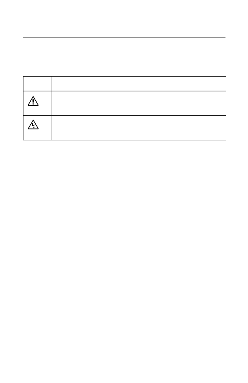
Safety Symbols Used in this Document
This document uses the safety symbols defined in Table 1.
Table 1. Safety Symbols
Symbol Meaning Description
Caution Performing or omitting a specific action may result in
equipment damage or loss of data.
Warning Performing or omitting a specific action may result in
electrical shock.
10
Page 11

AT-MCF2000 Multi-channel Media Converter Chassis Installation Guide
Where to Find Web-based Guides
The installation and user guides for all Allied Telesis
products are available in portable document format (PDF)
on our web site at www.alliedtelesis.com. You can view
the documents online or download them onto a local
workstation or server.
For details about the features and functions of the AT-S85
and AT-S97 Management Software, the AT-MCF2000M
Management Module, and the AT-MCF2000S Stacking
Module, refer to the following manuals on our web site:
AT-S85 and AT-S97 Management Software Command
Line Interface User’s Guide (part number 613-000789)
AT-MCF2000M Management Module Installation Guide
(part number 613-000709)
AT-MCF2000S Stacking Module Installation Guide
(part number 613-000708)
11
Page 12

Preface
Contacting Allied Telesis
This section provides Allied Telesis contact information for
technical support as well as sales and corporate
information.
Online
Support
Email and
Telephone
Support
Warranty
Registration
Returning
Products
Sales or
Corporate
Information
You can request technical support online by accessing the
Allied Telesis Knowledge Base: www.alliedtelesis.com/
support. You can use the Knowledge Base to submit
questions to our technical support staff and review answers
to previously asked questions.
For Technical Support via email or telephone, refer to the
Support & Services section of the Allied Telesis web site:
www.alliedtelesis.com.
The AT-MCF2000 Chassis has a 2 year warranty. For
warranty information or to register your product, go to the
Allied Telesis web site at www.alliedtelesis.com/
warranty.
Products for return or repair must first be assigned a return
materials authorization (RMA) number. A product sent to
Allied Telesis without an RMA number will be returned to
the sender at the sender’s expense.
To obtain an RMA number, contact Allied Telesis Technical
Support through our web site: www.alliedtelesis.com.
You can contact Allied Telesis for sales or corporate
information through our web site at
www.alliedtelesis.com.
Management
Software
Updates
12
New releases of management software for our managed
products are available from the following Internet sites:
Allied Telesis web site: www.alliedtelesis.com
Allied Telesis FTP server: ftp://ftp.alliedtelesis.com
If the FTP server prompts you to log on, enter “anonymous”
as the user name and your email address as the password.
Page 13

Chapter 1
Overview
This chapter contains the following sections:
“Hardware Features” on page 15
“Media Converter Module Slots” on page 16
“Management Module Slot” on page 16
“Power Supply Module and Fan Module Slots” on
page 19
The AT-MCF2000 chassis, shown in Figure 1, and the
AT-MCF2000 series of multi-channel media converter
modules are designed to interconnect Ethernet networking
devices over large distances by transferring Ethernet
network packets between twisted pair cable and fiber optic
cable.
The chassis can accommodate two multi-channel media
converter modules as well as the optional AT-MCF2000M
Management Module for either local (out-of-band) or
remote (in-band) network management of the ports on the
media converter modules. The unit also features slots for
two power supply units for power redundancy or one power
supply unit and one fan unit. You can install the unit on a
table or in a standard 19-inch rack.
A
T
M
A
C
T
-M
F
C
2
F
0
2
0
K
0
P
N
L
1
A
T-M
C
F
2
K
P
N
L
1
1
AT-MCF2000
2
1106-a
Figure 1. AT-MCF2000 Chassis
13
Page 14

Chapter 1: Overview
Note
For a list of available media converter modules for the
AT-MCF2000 chassis, contact your Allied Telesis sale
representative or visit our web site.
14
Page 15

Hardware Features
Figure 2 shows the front panel of the AT-MCF2000 chassis.
AT-MCF2000 Multi-channel Media Converter Chassis Installation Guide
AT-MCF2KPNL1 AT-MCF2KPNL1
1
Media Converter
Module Slots
Figure 2. Front Panel
Figure 3 illustrates the back panel of the AT-MCF2000
chassis.
AT-MCF2KPNL2 AT-MCF2KPNL2
Power Supply Module
A
Management Module
AT-MCF2KPNL3
MANAGEMENT
Slotor Fan Module Slot
B
Power Supply Module
or Fan Module Slot
Figure 3. Back Panel
AT-MCF2000
2
1107-a
1108-a
15
Page 16

Chapter 1: Overview
Media Converter Module Slots
The two slots on the front panel of the chassis are for the
media converter modules, such as the twelve channel
AT-MCF2012LC Fast Ethernet Media Converter Module.
Media converters are designed to interconnect networking
devices over large distances by transferring network traffic
between twisted pair cable and fiber optic cable. For a list of
available media converter modules for the AT-MCF2000
chassis, contact your Allied Telesis sale representative or
visit our web site. For background information and specific
installation instructions for a media converter module, refer
to the Installation Guide that ships with the module.
Management Module Slot
The management module slot on the back panel is intended
for either the AT-MCF2000M Management Module or the
AT-MCF2000S Stacking Module. See the following sections
for a description of these modules.
AT-
MCF2000M
Management
Module
16
The AT-MCF2000M Management Module allows you to
configure the operating parameters of the media converter
modules, such as the speed and duplex mode of the ports,
and monitor the status of the modules and channels. See
Figure 4.
AT-MCF2000M
ST
A
C
KM
LINK
ACT
A
N
AG
E
M
1000 LIN
E
N
T
K
ACT 10/10
TE
0 LINK ACT
R
M
IN
A
L
FDX
P
O
R
T
HDX COL
A
C
T
IV
IT
Y
1
0
/1
0
0
/
1
0
0
0
B
A
S
R
E
S
E
T
B
O
O
E
-T
R
S-232
T
R
D
Y
FA
U
L
T
SD
R
D
Y
B
U
S
Y
1198a
M
A
S
TE
R
POW
E
R
Figure 4. AT-MCF2000M Management Module
Page 17

AT-MCF2000 Multi-channel Media Converter Chassis Installation Guide
The AT-MCF2000M Management Module is an optional
module. The media converter modules can forward network
traffic without the presence of this module in the chassis.
However, the management module is necessary if you want
to adjust the parameter settings of a media converter
module, monitor the performance of the modules, or create
a stack of modules.
For more information about the management module, see
the AT-MCF2000M Management Module Installation Guide.
AT-
MCF2000S
Stacking
Module
You can use the AT-MCF2000 chassis as a standalone unit
or you can connect additional units to create a stack. A
stack merges and synchronizes the network operations of
two or more AT-MCF2000 chassis to form a single, logical
unit where the management functions span all of the ports
in the stack.
To create a stack of AT-MCF2000 chassis, you need to
have at least two chassis. Install the AT-MCF2000M
Management Module in one chassis. This becomes the
master chassis. Then install an AT-MCF2000S Stacking
Module in the second chassis. This chassis is called a
member chassis. See Figure 5.
A
T-MCF2000S
ST
A
C
K
1
L
IN
KA
P
O
C
R
T
T
AC
T
IVIT
S
Y
T
A
C
K
2
C
H
A
S
S
IS
ID
1264
Figure 5. AT-MCF2000S Stacking Module
In an AT-MCF2000 stack, there is one master chassis and
one to seven member chassis. With the management
module installed in the master chassis, you can stack up to
seven additional chassis that have the AT-MCF2000S
Stacking Module installed. In a stack that contains eight
chassis, you can install up to 16 media converter modules.
17
Page 18

Chapter 1: Overview
Each chassis has a chassis ID. By default, the management
module is assigned a chassis ID of 0. For each stacking
module, you must assign a chassis ID which is displayed on
the front of the module. The permitted values of the chassis
ID for stacking modules are from 1 to 30. For more
information about the stacking module, see the AT-
MCF2000S Stacking Module Installation Guide.
18
Page 19

AT-MCF2000 Multi-channel Media Converter Chassis Installation Guide
Power Supply Module and Fan Module Slots
The AT-MCF2000 chassis has two slots on the back panel
for two power supplies or one power supply and one
AT-MCF2KFAN fan module.
The power requirements of the AT-MCF2000 chassis and
the media converter modules can be met with a single
power supply. However, a second power supply can be
installed in the system to add power redundancy and
protect the system from a power supply or power circuit
failure.
Allied Telesis offers the AT-MCF2000AC power supply
module for the AT-MCF2000 chassis. This is an AC power
supply.
If you install two power supply modules in the chassis, they
share the load of powering the unit during normal
operations. If one power supply fails or loses power, the
remaining unit provides all of the power to the system to
protect the unit from a system failure.
Note
A redundant power supply is strongly recommended
for the AT-MCF2000 chassis to avoid a “single point of
failure” to your network links.
If you choose not to install a second power supply in the
chassis, you must install the AT-MCF2KFAN fan module so
that the chassis can maintain adequate cooling of the media
converter modules.
Warning
The AT-MCF2000 chassis must have two power
supply modules or one power supply module and one
fan module. Operating the AT-MCF2000 chassis
without a second power supply or the AT-MCF2KFAN
fan module may result in damage to the media
converter modules from overheating.
You can hot swap the power supply and fan modules. That
is, they can be removed and replaced with another module
while the unit is operating.
19
Page 20

Chapter 1: Overview
20
Page 21

Chapter 2
Installation
This chapter contains the following sections:
“Reviewing Safety Precautions” on page 22
“Selecting a Site for the AT-MCF2000 Chassis” on
page 24
“Unpacking the AT-MCF2000 Chassis” on page 25
“Installing the Chassis in a Rack” on page 26
“Installing the AT-MCF2000AC Power Supply Module”
on page 28
“Installing the AT-MCF2KFAN Fan Module” on page 32
“Installing a Media Converter Module” on page 35
“Cabling a Media Converter Module” on page 39
“Powering On the Chassis” on page 40
“Removing a Module from the Chassis” on page 42
21
Page 22

Chapter 2: Installation
Reviewing Safety Precautions
Please review the following safety precautions before you
begin to install the AT-MCF2000 chassis.
Note
The indicates that a translation of the safety
statement is available in a PDF document titled
“Translated Safety Statements” (613-000405) posted
on the Allied Telesis website at www.alliedtelesis.com.
This document is also included with the
documentation CD that is shipped with the product.
Note
To determine whether the fiber optic ports on a media
converter module are Class 1 Laser or Class 1 LED,
refer to the module’s Installation Guide.
Warning: Class 1 Laser product.
L1
Warning: Do not stare into the laser beam.
L2
Class 1 LED product. L3
Warning: Do not work on equipment or cables
during periods of lightning activity.
Warning: Class 1 Equipment: This equipment
must be earthed. The power plug must be
connected to a properly wired earth ground
socket outlet. An improperly wired socket outlet
could place hazardous voltages on accessible
metal parts. E4
Pluggable Equipment. The socket outlet shall be
installed near the equipment and shall be easily
accessible.
22
E5
E2
Page 23

AT-MCF2000 Multi-channel Media Converter Chassis Installation Guide
Caution: Air vents must not be blocked and
must have free access to the room ambient air
E6
E14
E7
E17
E16
E8
for cooling.
Warning: Operating Temperature. This product
is designed for a maximum ambient temperature
of 40° degrees C.
All Countries: Install product in accordance with
local and National Electrical Codes.
Warning: Only trained and qualified personnel
are allowed to install or to replace this
equipment.
Caution: Do not install in direct sunlight, or a
damp or dusty place.
Caution: Do not expose the gateway device to
moisture or water.
Warning: Mounting of the equipment in the rack
should be such that a hazardous condition is not
created due to uneven mechanical loading.
E25
Caution: Installation of the equipment in a rack
should be such that the amount of air flow
required for safe operation of the equipment is
not compromised. E36
23
Page 24

Chapter 2: Installation
Selecting a Site for the AT-MCF2000 Chassis
Observe the following guidelines when choosing a site for
the AT-MCF2000 media converter chassis:
The power outlet should be located near the unit and be
easily accessible.
The site should provide easy access to the ports on the
front of the chassis. This will make it easy for you to
connect and disconnect cables, as well as view the
unit’s LEDs.
To allow proper cooling of the switch, air flow around the
unit and through its vents on the side and rear should be
unrestricted.
Do not place objects on top of the chassis.
Do not expose the device to moisture or water.
Make sure that the site is in a dust-free environment.
Use dedicated power circuits or power conditioners to
supply reliable electrical power to the network devices.
If you plan to install the chassis in an equipment rack,
the rack should be safely secured to prevent it from
tipping over. Devices in a rack should be installed
starting at the bottom, with the heavier devices near the
bottom of the rack.
If you are installing the chassis on a table, be sure the
table is level and secure.
Keep the media converter chassis and twisted pair
cabling away from sources of electrical noise, such as
radios, electric motors, transmitters, broadband
amplifiers, power lines, and fluorescent fixtures.
24
Page 25

AT-MCF2000 Multi-channel Media Converter Chassis Installation Guide
Unpacking the AT-MCF2000 Chassis
To unpack the chassis, perform the following procedure:
1. Remove all components from the shipping package.
Note
Store the packaging material in a safe location. You
must use the original shipping material if you need to
return the unit to Allied Telesis.
2. Verify that the following items are included in the
shipping package. If an item is missing or damaged,
contact your Allied Telesis sales representative for
assistance.
One AT-MCF2000 Media Converter Chassis
Two 19-inch rack-mount brackets
Eight flathead Phillips rack-mount bracket screws
This Installation Guide
25
Page 26

Chapter 2: Installation
Installing the Chassis in a Rack
This procedure explains how to install the chassis in a 19inch rack. Depending on its placement in the rack, it may be
easier for you to install all of the modules in the chassis
before you mount it in the rack. If so, you can perform steps
1 through 3 in this procedure and then go to the next
procedure to begin to install the modules. After the modules
are installed, return to this section and complete the
procedure starting with step 4.
Installing the chassis in a rack is optional. The unit can be
installed on a desktop.
To install the chassis in a standard 19-inch rack, perform
the following procedure:
Note
Steps 1 to 3 are optional. They instruct you to remove
the plastic feet from the bottom panel of the chassis.
The plastic feet are unnecessary when the chassis is
installed in a rack.
1. Place the unit upside down on a level, secure surface.
2. Using a flat-head screwdriver, remove the snap-on
plastic feet from the bottom of the chassis, as shown in
Figure 6.
Figure 6. Removing the Chassis Feet
3. Turn the chassis over.
26
Page 27

A
T
-MCF2KPNL1
AT-MCF2000 Multi-channel Media Converter Chassis Installation Guide
4. Attach a rack-mount bracket to one side of the chassis
using four of the screws included with the unit, as
shown in Figure 7.
A
T
-M
C
F2
00
0
A
T-MCF2KPNL1
1
AT-MCF2000
2
1109-a
Figure 7. Attaching the Rack-Mount Brackets
5. Install the second rack-mount bracket on the other side
of the chassis using the four remaining screws.
6. Mount the switch in the 19-inch rack using standard
screws (not provided).
Caution
The chassis may be heavy. You may need assistance
to safely install the chassis in the rack.
27
Page 28

Chapter 2: Installation
Installing the AT-MCF2000AC Power Supply Module
This procedure explains how to install the AT-MCF2000AC
Power Supply Module.
Caution
The chassis must have two power supply modules or
one power supply module and one fan module to
maintain adequate airflow and cooling of the media
converter modules. For further information, refer to
“Power Supply Module and Fan Module Slots” on
page 19.
To install the AT-MCF2000AC Power Supply Module,
perform the following procedure:
1. Remove the power supply module from the shipping
package.
Note
Store the packaging material in a safe location. You
must use the original shipping material if you need to
return the unit to Allied Telesis.
2. Verify that the following items are included in the
shipping container.
One AT-MCF2000AC Power Supply Module
Four regional AC power supply cords
One power cord retaining clip
AT-MCF2000AC Power Supply Module
Installation Guide
28
Page 29

AT-MCF2000 Multi-channel Media Converter Chassis Installation Guide
AT-M
CF2KPN
L2
3. Remove the AT-MCF2KPNL2 blank panel from one of
the power supply/fan module slots on the back panel of
the chassis by loosening the two captive screws on the
panel with a cross-head screwdriver. Refer to Figure 8.
The power supply module can be installed in either
power supply/fan module slot.
A
A
T-M
M
CF2KPN
A
L3
1111-a
Figure 8. Removing the Blank Panel from a Power Supply/
Fan Module Slot
4. Slide the module into the slot as shown in Figure 9,
until it is flush with the back panel of the chassis.
You may need to exert light pressure to seat the
module in the connector on the back panel of the
chassis.
Caution
Do not force the module into place. Doing so may
damage the connector pins on the backplane inside
the chassis.
29
Page 30

Chapter 2: Installation
A
STATUS
P
S
N
U
O
R
M
A
L
F
A
U
L
T
F
A
N
Figure 9. Installing the AT-MCF2000AC Power Supply
Module
5. Secure the power supply module to the chassis by
tightening the two captive screws on the module using
a cross-head screwdriver. Refer to Figure 10.
STA
TU
S
PSU
NORMAL
FAU
LT
FAN
A
AT-MCF2KPNL
AT-MCF2KPN
M
A
N
A
G
L3
1111-a
M
3
1113-a
Figure 10. Securing the AT-MCF2000AC Power Supply
Module
30
Page 31

AT-MCF2000 Multi-channel Media Converter Chassis Installation Guide
6. Locate the retaining clip brackets on either side of the
AC power connector. Refer to Figure 11.
STATU
S
PSU
N
OR
M
AL
FA
U
LT
FA
N
A
AT-
MCF2KPNL
M
3
Retaining Clip Brackets
Figure 11. Locating the Retaining Clip Brackets
7. Position the retaining clip as shown in Figure 12 and
press the sides of the clip towards the center while
inserting the short ends into the holes in the bracket.
STATU
S
PS
N
U
O
RM
A
L
FA
U
LT
FAN
A
AT-M
M
C
F2K
PN
L3
1114-a
Figure 12. Installing a Retaining Clip
8. Repeat this procedure to install a second power supply
module or go to the next procedure to install the
AT-MCF2KFAN Fan Module.
31
Page 32

Chapter 2: Installation
Installing the AT-MCF2KFAN Fan Module
This procedure explains how to install the AT-MCF2KFAN
Fan Module.
Caution
The AT-MCF2000 chassis must have two power
supply modules or one power supply module and one
fan module to maintain adequate airflow and cooling
of the media converter modules.
Note
The AT-MCF2KFAN module draws its power from the
backplane of the chassis. It does not have a power
cord.
Note
The AT-MCF2KFAN module supports hot swapping.
This means you can install or replace the module
while the chassis is powered on.
To install the fan module, perform the following procedure:
1. Remove the fan module from the shipping package.
Note
Store the packaging material in a safe location. You
must use the original shipping material if you need to
return the unit to Allied Telesis.
2. Verify that the AT-MCF2KFAN shipping container
contains the following items. If an item is missing or
damaged, contact your Allied Telesis sales
representative for assistance.
One AT-MCF2KFAN Fan Module
AT-MCF2KFAN Fan Module Installation Guide
32
Page 33

AT-MCF2000 Multi-channel Media Converter Chassis Installation Guide
1125-a
M
A
N
A
G
E
M
E
N
T
B
AT-MCF2KFAN
N
O
R
M
A
L
FAULT
ST
A
TU
S
3. Remove the AT-MCF2KPNL2 blank panel from one of
the power supply/fan module slots on the back panel of
the chassis by loosening the two captive screws on the
panel with a cross-head screwdriver. Refer to Figure 8
on page 29. The fan module can be installed in either
of the power supply/fan module slots.
Note
Do not remove a blank panel from the chassis until
you are ready to install a module, especially if the
device is powered on. An open slot allows dust to
enter the unit and impedes the ability of the chassis to
maintain proper airflow and cooling.
4. Slide the fan module into the slot as shown in Figure
13, until it is flush with the back panel of the chassis.
You may need to exert light pressure to seat the
module in the connector on the back panel of the
chassis.
Caution
Do not force the module into place. Doing so may
damage the connector pins on the backplane inside
the chassis.
Figure 13. Installing the AT-MCF2KFAN Fan Module
33
Page 34

Chapter 2: Installation
A
T-MCF2KFAN
NORMAL
FAULT
S
T
ATU
S
M
A
N
AG
E
M
E
N
T
B
5. Secure the fan module to the chassis by tightening the
two captive screws on the module using a cross-head
screwdriver. Refer to Figure 14.
1125-b
Figure 14. Securing the AT-MCF2KFAN Fan Module
34
Page 35

AT-MCF2000 Multi-channel Media Converter Chassis Installation Guide
Installing a Media Converter Module
This section contains general instructions on how to install a
media converter module in the chassis. For specific
installation and cabling instructions, refer to the Installation
Guide that ships with the media converter module.
Caution
A media converter module is sensitive to and can be
damaged by electrostatic discharge. Wear a
grounding device and observe electrostatic discharge
precautions when installing a media converter module
in the chassis.
Note
Refer to the Installation Guide that ships with the
media converter module for the following information
before you install the module in the AT-MCF2000
chassis:
Determine if the module supports hot swapping. If
the module does not support hot swapping, you
must power off the chassis before installing the
module.
Determine if there are any DIP switches on the
circuit board of the media converter module that
need to be set. If there are switches, set them in
accordance with your network requirements by
following the instructions in the module’s
Installation Guide.
Determine if the module has a battery with an
insulator that must be removed prior to
installation. If there is an insulator, remove it by
following the instructions in the module’s
Installation Guide.
35
Page 36

Chapter 2: Installation
To install a media converter module, perform the following
procedure:
1. Using a cross-head screwdriver, remove an
AT-MCF2KPNL1 blank panel from a media converter
slot on the front panel of the chassis. A media
converter module can be installed in either slot. Refer
to Figure 15.
Note
Do not remove a blank panel from the chassis until
you are ready to install a module, especially if the
device is powered on. An open slot allows dust to
enter the unit and impedes the ability of the chassis to
maintain proper airflow and cooling.
A
T-M
C
F
2
0
0
0
1
AT-MCF2000
2
1120-a
Figure 15. Removing a Blank Cover from a Media
Converter Slot
2. Unpack the media converter module from its shipping
container.
Note
Store the packaging material in a safe location. You
must use the original shipping material if you need to
return the unit to Allied Telesis.
36
Page 37

AT-MCF2000 Multi-channel Media Converter Chassis Installation Guide
1121-a
3. Align the edge of the module with the guides in the slot
and carefully slide the module into the chassis until it is
flush with the front of the chassis. Refer to Figure 16.
Light pressure may be necessary to seat the module
on the connector on the back panel of the chassis.
Caution
Do not force the module into place. Doing so may
damage the connector pins on the backplane inside
the chassis. If there is resistance, remove the module
and reinsert it after verifying that the edges of the card
are properly aligned with the guides in the chassis’
module slot.
AT-M
CF
20
0
0
AT-MCF2012LC
1
Figure 16. Installing a Media Converter Module
37
Page 38

Chapter 2: Installation
1122-a
4. Secure the media converter module to the chassis by
tightening the two captive screws on the module using
a cross-head screwdriver. Refer to Figure 17.
AT-MCF2012LC
1
Figure 17. Securing a Media Converter Module
5. Repeat this procedure to install a second media
converter module in the chassis.
6. To install the chassis in a rack, return to “Installing the
Chassis in a Rack” on page 26. Otherwise, continue to
the next procedure to connect network cables the
media converter module.
38
Page 39

AT-MCF2000 Multi-channel Media Converter Chassis Installation Guide
Cabling a Media Converter Module
This section contains general guidelines to attaching the
network cables to the ports on a media converter module.
For additional instructions and guidelines, refer to the
Installation Guide that ships with the module.
Refer to the cabling specifications in the module’s
Installation Guide to verify that you are using the correct
type of cable and are not exceeding the maximum
operating distance of the ports.
Do not remove the dust cover from a fiber optic port until
you are ready to connect the cable. Dust contamination
can adversely impact the operation of the port.
Verify that the operating specifications of the fiber optic
ports on the networking devices are compatible with the
fiber optic ports on the media converter module.
A connector or a twisted pair or fiber optic cable should
fit snugly into the port on the module. It should firmly
lock into place on the port.
39
Page 40

Chapter 2: Installation
A
T
-MC
F
2
K
PN
L
3
NORMAL
FAU
LT
STATU
S
PSU
FAN
Powering On the Chassis
To apply power to the AT-MCF2000AC power supply
module and the AT-MCF2000 chassis, perform the
following procedure:
1. Verify that the power switch on the module is set to
OFF.
2. Plug the appropriate power cord for your region or
country into the AC power connector on the back panel
of the unit and plug the other end into an appropriate
power source. Refer to “Power Specifications” on
page 48 or the AT-MCF2000AC Power Supply Module
Installation Guide for the power requirements of the
chassis and the power module.
A
M
1116-a
Figure 18. Connecting the AC Power Cord
40
Page 41

AT-MCF2000 Multi-channel Media Converter Chassis Installation Guide
3. Lower the power cord retaining clip to secure the power
cord to the chassis and prevent it from being
inadvertently disconnected from the unit.
S
T
A
T
U
S
P
S
N
U
O
R
M
A
L
F
A
U
L
T
F
A
N
A
AT-MCF2KPNL
3
1117-a
M
Figure 19. Positioning the Power Cord Retaining Clip
4. Power on the AT-MCF2000AC module and the media
converter chassis by setting the power switch to ON.
5. If the unit has a second power supply, repeat this
procedure.
Note
If you installed two power supplies, Allied Telesis
recommends connecting the two power cords to
outlets on separate power supply circuits to increase
the protection to your media converter from a failure of
a power circuit.
This completes the installation procedure. For instructions
on how to verify the operation of the ports on a media
converter module, refer to the Installation Guide that ships
with the module.
41
Page 42

Chapter 2: Installation
Removing a Module from the Chassis
The procedures in this section explain how to remove a
module from the chassis. The procedures are:
“Removing an AC Power Supply Module” on page 42
“Removing a Fan Module” on page 42
“Removing a Media Converter Module” on page 43
Removing an
AC Power
Supply
Module
To remove the AT-MCF2000AC Power Supply Module,
perform the following procedure:
1. Set the power switch on the AT-MCF2000AC module
to OFF.
2. Disconnect the AC power cord from the power source.
3. Raise the power cord retaining clip and disconnect the
power cord from the power supply module.
4. Loosen the two captive screws that secure the power
supply module to the chassis using a cross-head
screwdriver.
5. Slide the power supply module from the unit.
Caution
If the chassis is operating with a second power supply,
you must replace the power supply module you just
removed with another power supply module or the
AT-MCF2KFAN fan unit. The chassis must have either
two power supply modules or one power supply
module and one fan module to maintain adequate
airflow and cooling.
Removing a
Fan Module
42
The AT-MCF2KFAN fan module supports hot swapping and
can be removed while the chassis is powered on. To
remove the module, perform the following procedure:
1. Loosen the two captive screws that secure the module
to the chassis using a cross-head screwdriver.
2. Slide the fan module from the unit.
Page 43

AT-MCF2000 Multi-channel Media Converter Chassis Installation Guide
Caution
You must replace the fan module with either another
fan module or a power supply module. The chassis
must have either two power supply modules or one
power supply module and one fan module to maintain
adequate airflow and cooling.
Removing a
Media
Converter
Module
Before removing a media converter module from the
chassis, refer to the module’s Installation Guide to
determine whether the module supports hot swapping. If it
does not, you must power off the chassis before performing
the procedure to avoid damaging the module.
Caution
A media converter module is sensitive to and can be
damaged by electrostatic discharge. Wear a
grounding device and observe electrostatic discharge
precautions when removing a media converter module
from the chassis.
To remove a media converter module, perform the following
procedure:
1. Disconnect all network cables from the ports on the
media converter module.
2. Reinsert the dust covers on the fiber optic ports.
3. Loosen the two captive screws that secure the module
to the chassis using a cross-head screwdriver.
4. Slide the module from the chassis.
5. Install another media converter module in the chassis’
slot or reinstall the AT-MCF2KPNL1 blank panel on the
slot.
Note
Do not leave the slot open. An open slot allows dust to
enter the unit and impedes the ability of the chassis to
maintain proper airflow and cooling.
43
Page 44

Chapter 2: Installation
44
Page 45

Chapter 3
Troubleshooting
This chapter offers suggestions on how to troubleshoot the
AT-MCF2000 chassis should a problem occur. For
instructions on how to troubleshoot a problem with a
media converter module or the optional management
module, refer to the instructions in the Installation Guide
that ships with the module.
Problem: The fans in the power supply module are not
operating.
Solution: The power supply module is not receiving power
or has failed. Alternatively, the fans have failed. Try the
following:
View the LEDs on the power supply module to
Verify that the module is fully seated in the power
Verify that the power cord is firmly connected to the
Verify that the power source is operating properly by
Replace the power supply module with another power
Verify that the power from the power source is within
determine whether the module is operating properly.
The description of the LEDs can be found in the
module’s Installation Guide.
supply/fan slot on the back panel of the chassis.
power supply module and the power source.
plugging a different device into it.
supply module.
the operating specifications of the power supply
module. For the operating specifications of the power
supply module, refer to the Installation Guide that ships
with the module.
Problem: The fans in the AT-MCF2KFAN module are not
operating.
Solution: The fan module is not receiving power or has
failed. Try the following:
Verify that the module is fully seated in the power
supply/fan slot in the chassis.
45
Page 46

Chapter 3: Troubleshooting
Verify that the power cord to the power supply module in
the chassis is firmly connected to the power supply
module and the power source.
View the LED on the fan module to determine whether
the module is operating properly. If the LED indicates
the fan module is receiving power but a fan has failed,
replace the fan module. The description of the LED can
be found in the module’s Installation Guide.
Remove and reinstall the fan module.
Replace the fan module with either another fan module
or a power supply module. If the replacement module
works, the problem is with the original fan module. If the
replacement module does not work, the problem is with
the chassis.
Note
If you need further assistance, please contact Allied
Telesis Technical Support. Refer to “Contacting Allied
Telesis” on page 12.
46
Page 47

Appendix A
Technical Specifications
Physical Specifications
Dimensions: 4.4 cm x 44.0 cm x 42.4 cm
Weight — Chassis with
blank faceplates: 5.5 kg (12.0 lb.)
Weight — Chassis with two
AT-MCF2000AC modules
and two AT-MCF2012LC
modules: 7.7 kg (17.0 lb.)
Environmental Specifications
Operating Temperature: 0° C to 40° C
(1.75 in x 17.3 in. x 16.7 in.)
(32° F to 104° F)
Storage Temperature: -20° C to 70° C
(-° 4F to 158° F)
Operating Humidity: Less than 80%
noncondensing
Storage Humidity: Less than 95%
noncondensing
Maximum Operating Altitude: 3,048 m (10,000 ft)
Maximum Non-operating Altitude: 4,000 m (13,000 ft)
47
Page 48

Appendix A: Technical Specifications
Power Specifications
Input Voltage: 100-240 VAC 50/60 Hz
Maximum Input Current: 2A
Power Consumption: 100 W (maximum)
Safety and Electromagnetic Emissions Certifications
EMI (Emissions): FCC Class A, EN55022 Class
A, EN61000-3-2, EN61000-33, VCCI Class A, C-TICK, CE
EMC (Immunity): EN55024
Electrical and Laser Safety: EN60950-1 (TUV),
UL 60950-1 (
EN60825
Quality and Reliability: MTBF > 100,000 hrs.
CULUS
),
Compliance Marks: CE,
48
CULUS
, TUV, C-Tick
 Loading...