

Page 1

AT-MC1004
AT-MC1005/1
AT-MC1005/2
AT-MC1005/3
AT-MC1005/4
Gigabit Ethernet Media Converters
Installation Guide
PN 613-50438-00 Rev A
Page 2

Copyright 2003 Allied Telesyn, Inc.
960 Stewart Drive, Suite B, Sunnyvale CA USA 94085
All rights reserved. No part of this publication may be reproduced without prior written
permission from Allied Telesyn, Inc.
Ethernet is a registered trademark of Xerox Corporation. All other product names,
company names, logos or other designations mentioned herein are trademarks or
registered trademarks of their respective owners.
Allied Telesyn, Inc. reserves the right to make changes in specifications and other
information contained in this document without prior written notice. The information
provided herein is subject to change without notice. In no event shall Allied Telesyn,
Inc. be liable for any incidental, special, indirect, or consequential damages whatsoever,
including but not limited to lost profits, arising out of or related to this manual or the
information contained herein, even if Allied Telesyn, Inc. has been advised of, known, or
should have known, the possibility of such damages.
Page 3

Electrical Safety and Emission Compliance Statement
Standards: This product meets the following standards
U.S. Federal Communications Commission
Declaration Of Conformity
Manufacturer Name: Allied Telesyn, Inc.
Manufacturer Address: 960 Stewart Drive, Suite B
Manufacturer Telephone: 408-730-0950
Declares that the product: Gigabit Ethernet Media
Model Numbers: AT-MC1004, AT-MC1005/1,
This product complies with FCC Part 15B, Class B Limits:
This device complies with part 15 of the FCC Rules. Operation is subject
to the following two conditions: (1) This device must not cause harmful
interference, and (2) this device must accept any interference received,
including interference that may cause undesired operation.
Radiated Energy
Note: This equipment has been tested and found to comply with the
limits for a Class B digital device pursuant to Part 15 of FCC Rules.
These limits are designed to provide reasonable protection against
harmful interference in a residential installation. This equipment
generates, uses and can radiate radio frequency energy and, if not
installed and used in accordance with instructions, may cause harmful
interference to radio or television reception, which can be determined by
turning the equipment off and on. The user is encouraged to try to correct
the interference by one or more of the following measures:
- Reorient or relocate the receiving antenna.
- Increase the separation between the equipment and the receiver.
- Connect the equipment into an outlet on a circuit different from that to
which the receiver is connected.
- Consult the dealer or an experienced radio/TV technician for help.
Changes and modifications not expressly approved by the manufacturer
or registrant of this equipment can void your authority to operate this
equipment under Federal Communications Commission rules.
Sunnyvale, CA 94085 USA
Converters
AT-MC1005/2, AT-MC1005/3,
AT-MC1005/4
Warning: This product requires Category 5 shielded twisted-pair or
better for RJ-45 connections to comply with Class B emission limits. If
not used with shielded cables, this product may cause radio interference
in which case the user may be required to take adequate measures to
reduce interference levels.
iii
Page 4
Electrical Safety and Emission Compliance Statement
Industry Canada
This Class B digital apparatus meets all requirements of the Canadian
Interference-Causing Equipment Regulations.
Cet appareil numérique de la classe B respecte toutes les exigences du
Règlement sur le matériel brouilleur du Canada.
RFI Emission EN55022 Class B
Warning: In a domestic environment this product may cause radio
interference in which case the user may be required to take adequate
measures.
Immunity EN55024
Electrical Safety TUV-EN60950, UL1950, CSA 950
Laser EN60825
Important: Appendix B contains translated safety statements for installing
this equipment. When you see the
safety statement in your language.
Wichtig: Anhang B enthält übersetzte Sicherheitshinweise für die
Installation dieses Geräts. Wenn Sie
den übersetzten Sicherheitshinweis in Ihrer Sprache nach.
Vigtigt: Tillæg B indeholder oversatte sikkerhedsadvarsler, der vedrører
installation af dette udstyr. Når De ser symbolet
B og finde de oversatte sikkerhedsadvarsler i Deres eget sprog.
Belangrijk: Appendix B bevat vertaalde veiligheidsopmerkingen voor het
installeren van deze apparatuur. Wanneer u de
B voor vertaalde veiligheidsinstructies in uw taal.
Important: L'annexe B contient les instructions de sécurité relatives à
l'installation de cet équipement. Lorsque vous voyez le symbole
reportez-vous à l'annexe B pour consulter la traduction de ces instructions
dans votre langue.
Tärkeää: Liite B sisältää tämän laitteen asentamiseen liittyvät käännetyt
turvaohjeet. Kun näet
liitteestä B.
Importante: l’Appendice B contiene avvisi di sicurezza tradotti per
l’installazione di questa apparecchiatura. Il simbolo
l’Appendice B per l’avviso di sicurezza nella propria lingua.
Viktig: Tillegg B inneholder oversatt sikkerhetsinformasjon for installering
av dette utstyret. Når du ser
oversatte sikkerhetsinformasjonen på ønsket språk.
Importante: O Anexo B contém advertências de segurança traduzidas para
instalar este equipamento. Quando vir o símbolo
segurança traduzida no seu idioma no Anexo B.
Importante: El Apéndice B contiene mensajes de seguridad traducidos para
la instalación de este equipo. Cuando vea el símbolo
para ver el mensaje de seguridad traducido a su idioma.
Obs! Bilaga B innehåller översatta säkerhetsmeddelanden avseende
installationen av denna utrustning. När du ser
för att läsa det översatta säkerhetsmeddelandet på ditt språk.
2
-symbolin, katso käännettyä turvaohjetta
1
3
5
, go to Appendix B for the translated
sehen, schlagen Sie in Anhang B
, skal De slå op i tillæg
ziet, raadpleeg Appendix
,
, indica di consultare
, åpner du til Tillegg B for å finne den
, leia a advertência de
, vaya al Apéndice B
, skall du gå till Bilaga B
4
iv
Page 5

Table of Contents
Electrical Safety and Emission Compliance Statement .......................iii
Table of Contents ............................................................................................ v
Preface ............................................................................................................. vii
Where to Find Web-based Guides ...................................................................vii
Document Conventions ....................................................................................vii
Contacting Allied Telesyn Technical Support................................................viii
Online Support .........................................................................................viii
Telephone Support ...................................................................................viii
E-mail Support .........................................................................................viii
Returning Products ........................................................................................... ix
For Sales or Corporate Information ................................................................. ix
Tell Us What You Think ................................................................................... ix
Chapter 1
Overview ........................................................................................................... 1
Key Features....................................................................................................... 3
Status LEDs ................................................................................................ 3
Fiber Optic Port........................................................................................... 4
Mode Selection Button ....................................................................................... 4
Link Test...................................................................................................... 4
MissingLink ................................................................................................. 4
Smart MissingLink ..................................................................................... 5
Half- and Full-Duplex Mode ....................................................................... 6
External AC/DC Power Adapter................................................................. 6
Network Topologies ............................................................................................ 7
Standalone Topology ................................................................................... 7
Back-to-Back Topology ................................................................................ 8
v
Page 6

Table of Contents
Chapter 2
Installing the Media Converter ................................................................... 9
Verifying the Package Contents ........................................................................ 9
Planning the Installation............................................................................ 9
Selecting a Site .......................................................................................... 10
Reviewing Safety Guidelines .................................................................... 11
Installing the Media Converter ....................................................................... 12
Warranty Registration ..................................................................................... 14
Chapter 3
Troubleshooting............................................................................................ 15
Appendix A
Technical Specifications ............................................................................. 17
Physical ............................................................................................................. 17
Temperature ..................................................................................................... 17
Electrical Rating............................................................................................... 17
Agency Certifications ....................................................................................... 17
Fiber Optic Port Specifications ........................................................................ 18
RJ-45 Pin Assignments .................................................................................... 19
Appendix B
Translated Safety Statements.................................................................... 21
vi
Page 7
Preface
This guide contains instructions on how to install the AT-MC1004 and the
AT-MC1005/x Series Gigabit Ethernet Media Converters.
Where to Find Web-based Guides
The Allied Telesyn web site at www.alliedtelesyn.com provides you with an
easy way to access the most recent documentation and technical information
for all of our products. All web-based documents relating to this product and
other Allied Telesyn products, can be downloaded from the web site in PDF
format.
Document Conventions
This guide uses the following conventions:
Note
Notes provide additional information.
Caution
Cautions indicate that performing or omitting a specific action may
result in equipment damage or loss of data.
Warning
Warnings indicate that performing or omitting a specific action may
result in bodily injury.
vii
Page 8

Preface
Contacting Allied Telesyn Technical Support
You can contact Allied Teleysn technical support online or by telephone or
e-mail.
Online Support
You can request technical support online accessing the Knowledge Base at
http://kb.alliedtelesyn.com. You can use the Knowledge Base to submit
questions to our technical support staff and review answers to previously
asked questions.
Telephone Support
For technical support by telephone, contact Allied Telesyn at one of the
following locations:
Americas
United States, Canada, Mexico,
Central America, South America
Tel: 1 (800) 428-4835
Asia
Singapore, Taiwan, Thailand,
Malaysia, Indonesia, Korea,
Philippines, China,
India, Hong Kong
Tel: (+65) 63815-612
Australia
Tel: 1 (800) 000-880
France
Belgium, Luxembourg,
The Netherlands, Middle East, Africa
Tel: (+33) 0-1-60-92-15-25
Germany
Switzerland, Austria, Eastern Europe
Tel: (+49) 30-435-900-126
Italy
Spain, Portugal, Greece, Turkey, Israel
Tel: (+39) 02-416-3-41
Japan
Tel: (+81) 3-3443-5640
United Kingdom
Denmark, Norway, Sweden, Finland
Tel: (+0044) 1-235-442560
E-mail Support
Latin America, Mexico, Puerto Rico, Caribbean, and Virgin Islands
latin_america@alliedtelesyn.com
Europe
support_europe@alliedtelesyn.com
viii
Page 9

AT-MC1004 and AT-MC1005/x Series Installation Guide
Returning Products
Products for return or repair must first be assigned a Return Materials
Authorization (RMA) number. A product sent to Allied Telesyn without a
RMA number will be returned to the sender at the sender’s expense.
To obtain an RMA number, contact Allied Telesyn’s Technical Support at one
of the following locations:
North America
Toll-free: 1-800-762-1664
Fax: 1-425-806-1050
Latin America, the Caribbean, and
Virgin Islands
Tel: international code + 425-481-3852
Fax: international code + 425-481-3895
Mexico
Toll-free: 800-424-5012, ext 3852
Fax: international code + 425-481-3895
Australia
Toll-free: 1-800-000-880
Fax: +61-2-9438-4966
Europe, Africa, and the Middle
East
Tel: +44-1793-501401
Fax: +44-1793-431099
Puerto Rico
Tel: 1-800-424-5012, ext 3852
or
1-800-424-4284, ext 3852
Asia and Southeast Asia
Tel: +65-6381-5612
Fax: +65-6383-3830
New Zealand
Toll-free: 0800-45-5782
For Sales or Corporate Information
You can contact Allied Telesyn for sales or corporate information at the
location below:
Allied Telesyn, Inc.
19800 North Creek Parkway, Suite 200
Bothell, WA 98011
Tel: 1 (425) 487-8880
Fax: 1 (425) 489-9191
Tell Us What You Think
If you have any comments or suggestions on how we might improve this or
other Allied Telesyn documents, please fill out the General Enquiry Form at
online. This form can be accessed by selecting “Contact Us” from
www.alliedtelesyn.com.
ix
Page 10

Page 11
Chapter 1
Overview
The AT-MC1004 and AT-MC1005/x Series Gigabit Ethernet Media Converters
are designed to extend the distance of your network by converting Gigabit
Ethernet data between twisted pair cabling and either multimode or singlemode fiber optic cabling.
The AT-MC1004 media converter features a 1000Base-SX fiber optic port and
a 1000Base-T twisted pair port. The fiber optic port has an SC connector and a
maximum operating distance of 550 meters (1,804 feet). The twisted pair port
has an RJ-45 connector and a maximum operating distance of 100 meters (328
feet).
The AT-MC1005/x media converters feature a 1000Base-LX fiber optic port
and a 1000Base-T twisted pair port. The fiber optic port has an SC connector
and a maximum operating distance of 10 kilometers (6.2 miles) to 70
kilometers (43.4 miles), depending on the model. The twisted pair port has an
RJ-45 connector and a maximum operating distance of 100 meters (328 feet).
These units operate at 1000 Mbps and feature full-duplex operation.
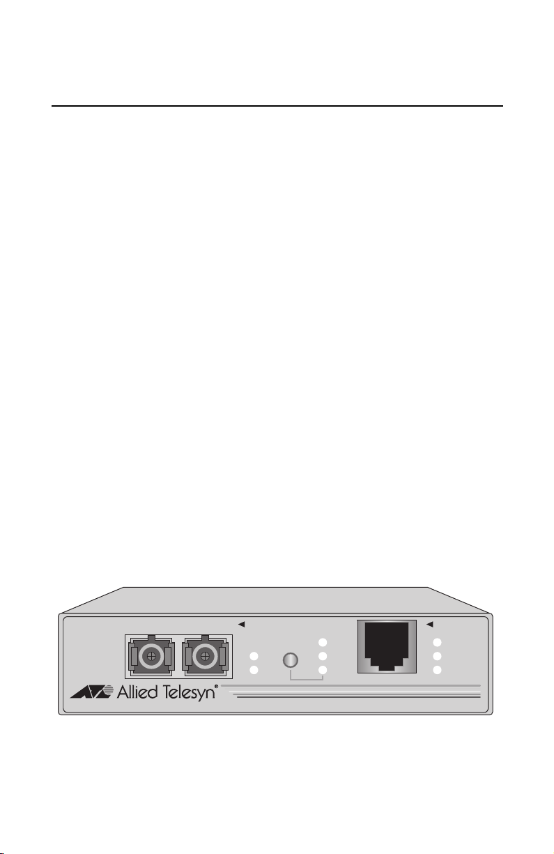
The AT-MC1004 and AT-MC1005/x Series Gigabit Ethernet Media Converters
can be used on a desktop or in an AT-MCR12 chassis. These units are easy to
install and do not require any software configuration or management. Figure
1 illustrates an AT-MC1004 media converter.
TX MM RX
1000Base-SX
MODE
LNK
ACT
ML
SML
LT
1000Base-T
PWR
LNK
ACT
V2
AT-MC1004 GIGABIT ETHERNET MEDIA CONVERTER
Figure 1 AT-MC1004 Gigabit Ethernet Media Converter
1
Page 12
Overview
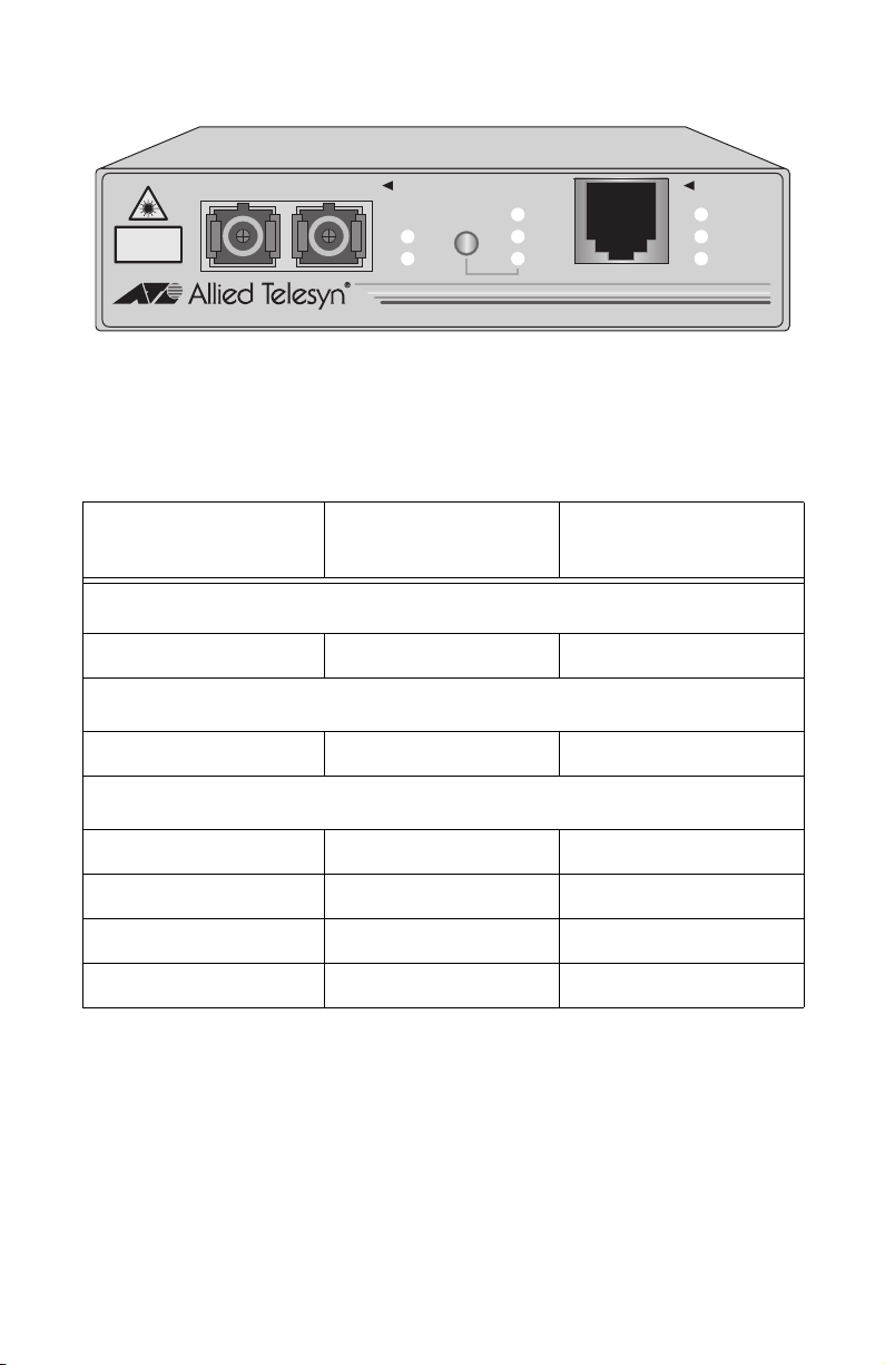
Figure 2 shows an example of an AT-MC1005/x Series Media Converter.
CLASS 1
LASER PRODUCT
DO NOT STARE
INTO BEAM
TX SM RX
1000Base-LX
MODE
LNK
ACT
ML
SML
LT
1000Base-T
PWR
LNK
ACT
V2
AT-MC1005/3 GIGABIT ETHERNET MEDIA CONVERTER
Figure 2 AT-MC1005/x Series Gigabit Ethernet Media Converter (Model AT-MC1005/3)
Table 1 lists the cabling distances for the Gigabit Ethernet media converters.
Table 1 Maximum Cabling Distances
Port Type of Connector Maximum Operating
Distance
1000Base-T
2
1
All Models RJ-45 100 m (328 ft)
1000Base-SX
AT-MC1004 SC 550 m (1,804 ft)
1000Base-LX
AT-MC1005/1 SC 10 km (6.2 mi)
AT-MC1005/2 SC 20 km (12.4 mi)
AT-MC1005/3 SC 40 km (24.8 mi)
AT-MC1005/4 SC 70 km (43.4 mi)
1. Maximum distance may be less depending on the type of fiber optic cabling used with the port.
2. The 1000Base-T port uses 4 pair (8 wires) in a twisted pair cable.
2
Page 13
AT-MC1004 and AT-MC1005/x Series Installation Guide
Key Features
The media converters have the following key features:
❑ LEDs for unit and port status
❑ 1000Base twisted pair port with a maximum operating distance of 100
meters (328 feet)
❑ 1000Base fiber optic port with a maximum operating distance of 550
meters (1,804 feet) to 70 kilometers (43.4 miles) using single-mode or
multimode fiber optic cabling, depending on the model
❑ Mode selection button that toggles between Link Test, MissingLink
and Smart MissingLink
❑ Full-duplex operation
❑ External AC/DC power adapter
❑ Standard, compact size for desktop use or with an AT-MCR12
rackmount chassis
Status LEDs
Table 2 defines the units LEDs.
Table 2 Status LEDs
LED Color Description
PWR Green Power is applied to the unit.
LNK Green A link has been established on the ports.
ACT Green Data is being received on the ports.
Mode Status
ML Green MissingLink is enabled.
,
SML Green Smart MissingLink is enabled.
LT Green Link Test is enabled.
3
Page 14

Overview
Fiber Optic Port
The 1000Base-SX port on the AT-MC1004 media converter has an SC
connector and is designed to operate with multimode fiber optic cabling. This
port has a maximum operating distance of 550 meters (1,804 feet) using 62.5/
125 micron multimode fiber optic cable.
The 1000Base-LX port on the AT-MC1005/x Series Media Converters has an
SC connector and is designed to operate with single-mode fiber optic cabling.
This port has a maximum operating distance of 10 kilometers (6.2 miles) to 70
kilometers (43.4 miles), depending on your model, using 9/125 micron singlemode fiber optic cable.
Mode Selection Button
Link Test
The link test is a fast and easy way for you to test the connections between the
Gigabit Ethernet media converter ports and the end-nodes that are connected
to the ports. If a network problem occurs, you can perform a link test to
determine which port is experiencing a problem, and be able to focus your
troubleshooting efforts on the cable and end-node where the problem resides.
A link test is performed when the Mode Selection button is toggled until the
LT LED is green.
Note
Performing a link test does not interfere with a media converter’s ability
to pass network traffic.
MissingLink
The MissingLink feature enables the fiber optic ports on the Gigabit Ethernet
media converter to pass the “Link” status of their connections to each other.
When the media converter detects a problem with one of the ports, such as the
loss of connection to an end-node, the media converter shuts down the
connection to the other port, thus notifying the end-node that the connection
has been lost.
4
Page 15

AT-MC1004 and AT-MC1005/x Series Installation Guide
For example, if the network twisted pair cable to the 1000Base-T port on the
media converter were to fail, the unit would respond by dropping the link on
the fiber optic port. In this way, the media converter notifies the end-node
connected to the fiber optic port that the connection on the twisted pair port
has been lost. If the failure had started with the fiber optic cabling, the unit
would drop the link to the twisted pair port.
The value to this type of network monitoring and fault notification is that
some devices can be configured to take a specific action in the event of the loss
of connection on a port. In some cases, the unit can be configured to seek a
redundant path to a disconnected end-node or send out a trap to a network
management station, and so alert the network administrator of the problem.
Note
MissingLink or Smart MissingLink is disabled when you perform a link
test. Consequently, to ensure that the MissingLink or Smart
MissingLink is enabled on the media converter, always set the Mode
Selection button so that the ML or SML LED is green during normal
network operations.
Smart MissingLink
Like MissingLink, the Smart MissingLink feature terminates the link on the
failed port thereby notifying you when a connection has been lost.
Additionally, Smart MissingLink indicates on which port the connection has
failed. This is shown by a blinking LNK LED on the good port.
For example, if the network twisted pair cable to the 1000Base-T port on the
media converter were to fail, the LNK LED on the fiber optic port will blink,
indicating a failed connection on the twisted pair port. The fiber optic port is
still able to receive a signal.
The media converter notifies the end-node connected to the fiber optic port
that the connection on the twisted pair port has been lost. If the failure had
started with the fiber optic cabling, the LNK LED on the twisted pair port
would blink.
The value to this type of network monitoring and fault notification is so that
you can quickly see which port has failed and troubleshoot your network
accordingly.
5
Page 16

Overview
Half- and Full-Duplex Mode
Duplex mode refers to the way an end-node sends and receives data on the
network. An end-node can operate in either half- or full-duplex mode,
depending on its capabilities. An end-node that is operating in half-duplex
mode can either send data or receive data, but it cannot do both at the same
time. An end-node that is operating in full-duplex mode can send and receive
data simultaneously. The best network performance is achieved when an endnode can operate at full-duplex, since the end-node is able to send and receive
data simultaneously.
The AT-MC1004 and AT-MC1005/x Series Gigabit Ethernet Media Converters
operate in full-duplex mode only. The media converter can operate with endnodes capable of either full-duplex mode or that can auto-negotiate the duplex
mode. However, it is important to remember that the two end-nodes connected
to the ports on the media converter must be able to operate in full-duplex
mode.
External AC/DC Power Adapter
An external AC/DC power adapter is included with the media converter for
desktop operation (see Figure 3). The power adapter supplies 12V DC to the
media converter. Allied Telesyn supplies an approved safety compliant AC
power adapter for the 120 and 240V AC versions with an unregulated output
of 12V DC at 1 A. The power required for the media converter is 12V DC,
1000 mA.
Note
The power adapter is not used if you install the media converter in an
AT-MCR12 chassis.
Figure 3 External AC/DC Power Adapter (North American version)
6
Page 17

AT-MC1004 and AT-MC1005/x Series Installation Guide
Network Topologies
The AT-MC1004 and AT-MC1005/x Series Gigabit Ethernet Media Converters
can be used in two different network topologies: standalone and back-to-back.
These network topologies are described below.
Standalone Topology
A standalone topology uses only one media converter between the end-nodes.
Figure 4 illustrates a standalone topology that uses two AT-MC1005/1 media
converters to interconnect three remote campuses. Campus 1 has an
AT-8224XL switch with two AT-A15/LX expansion modules. The modules,
which provide a connection of up to 10 kilometers (6.2 miles), are connected to
the 1000Base-LX ports on the media converters. The 1000Base-T ports on the
media converters are connected to the AT-A14 expansion modules in the
AT-8216FXL/MT switches at Campus 2 and Campus 3.
Campus 1: AT-8224XL with two
AT-A15/LX Expansion Modules
10BASE-T / 100BASE-TX
AT-A15
ACTIVITY
FAST ETHERNET SWITCH
LINK
A
10BASE-T / 100BASE-TX
1X 3X 5X 7X
B
2X 4X 6X 8X
9X 11X 13X 15X
10X 12X 14X 16X
FULL
1000BASE-X
HALF
AT-A15
ACTIVITY
LINK
FULL
1000BASE-X
HALF
10 km (6.2 mi) maximum
17X 19X 21X 23X
18X 20X 22X 24X
PORT ACTIVITY
L/A
100M LINK / ACTIVITY 10M LINK / ACTIVITY
D/C
FULL DUP
1234567891011121314151617181920212223
L/A
D/C
L/A
D/C
STATUS
RS-232
TERMINAL PORT
HALF DUP/
COL
FAULT
RPS
PWR
24
RESET
AT-MC1005/1
CLASS 1
LASER PRODUCT
DO NOT STARE
INTO BEAM
AT-MC1005/1 GIGABIT ETHERNET MEDIA CONVERTER
LNK
ACT
1000Base-LX
TX SM RX
MODE
1000Base-T
ML
SML
LT
V2
PWR
LNK
ACT
100 m (328 ft) maximum
100BASE-FX FAST ETHERNET SWITCH
AT-A14
ACTIVITY
LINK
A
FULL
1000BASE-X
HALF
L/A
D/C
B
1234 5678 9101112131415
100BASE-FX
L/A
L/A
L/A
L/A
L/A
L/A
L/A
L/A
L/A
D/C
D/C
D/C
D/C
D/C
D/C
D/C
D/C
D/C
PORT ACTIVITY
L/A
ACTIVITY
100M LINK
D/C
FULL DUP
HALF DUP/ COL
L/A
L/A
L/A
L/A
L/A
L/A
D/C
D/C
D/C
D/C
D/C
D/C
16
Campus 2: AT-8216FXL/MT with one
AT-A14 Expansion Module
Single-mode
Fiber Optic
Twisted Pair
Figure 4 Standalone Topology
AT-MC1005/1
CLASS 1
LASER PRODUCT
DO NOT STARE
INTO BEAM
AT-MC1005/1 GIGABIT ETHERNET MEDIA CONVERTER
LNK
ACT
1000Base-LX
TX SM RX
MODE
1000Base-T
ML
SML
LT
V2
PWR
LNK
ACT
100 m (328 ft) maximum
100BASE-FX FAST ETHERNET SWITCH
AT-A14
ACTIVITY
LINK
STATUS
RS-232
TERMINAL PORT
FAULT
RPS
PWR
RESET
A
FULL
1000BASE-X
HALF
L/A
L/A
L/A
L/A
L/A
L/A
D/C
D/C
D/C
D/C
D/C
D/C
B
1234 5678 9101112131415
100BASE-FX
L/A
L/A
D/C
D/C
L/A
L/A
L/A
L/A
L/A
L/A
L/A
D/C
D/C
D/C
D/C
D/C
D/C
STATUS
RS-232
PORT ACTIVITY
TERMINAL PORT
L/A
ACTIVITY
100M LINK
D/C
FULL DUP
HALF DUP/ COL
L/A
D/C
D/C
FAULT
RPS
PWR
16
RESET
Campus 2: AT-8216FXL/MT with one
AT-A14 Expansion Module
7
Page 18

Overview
Back-to-Back Topology
In some network configurations you may want to interconnect two media
converters in what is referred to as a back-to-back topology. In this topology,
the media converters not only extend the distance of your network but also
convert the fiber optic cable from twisted pair to fiber optic and back again.
Figure 5 illustrates one AT-8216FXL/MT switch with an AT-A14 expansion
module at each campus. The switches are interconnected by two AT-MC1005/3
media converters. The 1000Base-T ports on the media converters are
connected to the AT-A14 expansion modules in the switches, while the
1000Base-LX ports on the media converters are directly connected together.
Note
When using two media converters back-to-back, you must set both
converters to the same mode (ie. the first media converter is set to
MissingLink mode; then the second converter must also be set to
MissingLink mode.
Campus 1: AT-8216FXL/MT with one
AT-A14 Expansion Module
100BASE-FX FAST ETHERNET SWITCH
AT-A14
ACTIVITY
LINK
A
FULL
1000BASE-X
HALF
B
100BASE-FX
L/A
L/A
L/A
L/A
L/A
L/A
L/A
L/A
L/A
L/A
D/C
D/C
D/C
1 2 3 4 5 6 7 8 9 10 11 12 13 14 15
D/C
D/C
D/C
D/C
D/C
D/C
D/C
100 m (328 ft) maximum
L/A
L/A
L/A
L/A
D/C
D/C
D/C
D/C
STATUS
RS-232
PORT ACTIVITY
TERMINAL PORT
L/A
ACTIVITY
100M LINK
D/C
FULL DUP
HALF DUP/ COL
L/A
L/A
D/C
D/C
FAULT
RPS
PWR
16
RESET
AT-MC1005/3
Single-mode
Fiber Optic
Twisted Pair
8
1000Base-LX
TX SM RX
CLASS 1
LASER PRODUCT
DO NOT STARE
INTO BEAM
AT-MC1005/3 GIGABIT ETHERNET MEDIA CONVERTER
ACT
1000Base-T
V2
PWR
ML
MODE
LNK
SMLLTLNK
ACT
TX SM RX
CLASS 1
LASER PRODUCT
DO NOT STARE
INTO BEAM
AT-MC1005/3 GIGABIT ETHERNET MEDIA CONVERTER
40 km (24.8 mi) maximum
100 m (328 ft) maximum
AT-A14
ACTIVITY
LINK
A
FULL
1000BASE-X
HALF
B
Campus 2: AT-8216FXL/MT with
one AT-A14 Expansion Module
Figure 5 Back-to-Back Topology
1000Base-LX
ACT
100BASE-FX FAST ETHERNET SWITCH
L/A
D/C
1234 5678 9101112 131415
1000Base-T
V2
PWR
ML
MODE
LNK
SMLLTLNK
ACT
AT-MC1005/3
100BASE-FX
L/A
L/A
L/A
L/A
L/A
L/A
L/A
L/A
L/A
L/A
L/A
L/A
D/C
D/C
D/C
D/C
D/C
D/C
D/C
D/C
D/C
D/C
D/C
D/C
D/C
FAULT
RPS
PWR
16
RESET
STATUS
RS-232
PORT ACTIVITY
TERMINAL PORT
L/A
ACTIVITY
100M LINK
D/C
FULL DUP
HALF DUP/ COL
L/A
L/A
L/A
D/C
D/C
Page 19

Chapter 2
Installing the Media Converter
Verifying the Package Contents
Make sure the following items are included in your media converter package.
If any item is missing or damaged, contact your Allied Telesyn sales
representative.
❑ One AT-MC1004 or AT-MC1005/x Series Gigabit Ethernet Media
Converter
❑ Four protective feet (for desktop use only)
❑ External AC/DC power adapter (North America, Continental Europe,
United Kingdom, or Australia)
❑ This installation guide
❑ Warranty card
Planning the Installation
Be sure to observe the following guidelines when planning the installation of
your media converter.
❑ The end-nodes connected to the ports of the media converter must
operate in full-duplex mode. The AT-MC1004 and AT-MC1005/x
Series Gigabit Ethernet Media Converters operate only in full-duplex
mode.
❑ Refer to Table 3 and Table 4 for the twisted pair and fiber optic cabling
specifications.
9
Page 20

Installing the Media Converter
Table 3 Twisted Pair Cabling Specifications
Model Cable Maximum Operating
Distance
All Models Shielded Twisted Pair Category 5
100 m (328 ft)
or better
Note
The 1000Base-T ports use 4 pair (8 wires) in a twisted pair cable.
Table 4 Fiber Optic Cabling Specifications
Model Cable Maximum
Operating
Distance
Maximum
Allowable Loss
Budget
AT-MC1004 50/125 micron multimode 550 m (1,804 ft) 8.5 dB at 850 nm
62.5/125 micron
multimode
1
275 m (902 ft) 7.5 dB at 850 nm
AT-MC1005/1 9/125 micron single-mode 10 km (6.2 mi) 17.0 dB at 1310 nm
AT-MC1005/2 9/125 micron single-mode 20 km (12.4 mi) 18.0 dB at 1310 nm
AT-MC1005/3 9/125 micron single-mode
AT-MC1005/4 9/125 micron single-mode
1. Based on the multi-mode fiber cable with 200MHz per kilometer on the modal bandwidth @ 850 nm.
2. For maximum performance of Gigabit Optical Datalinks when greater than 40 km (24.8 mi) and operating within the
1550 nm optical spectrum, it is mandatory that the Single-mode Fiber (SMF) be rated as non-dispersion-shifted,
dispersion shifted, or non-zero dispersion shifted.
2
40 km (24.8 mi) 18.0 dB at 1550 nm
2
70 km (43.4 mi) 20.0 dB at 1550 nm
Selecting a Site
Be sure to observe the following requirements when choosing a site for your
media converter.
❑ Select a site that is dust-free and moisture-free.
❑ Be sure that the site will allow you to easily access the fiber optic and
twisted pair cables and the power cord.
❑ Use dedicated power circuits or power conditioners to supply reliable
power to the device.
10
Page 21

AT-MC1004 and AT-MC1005/x Series Installation Guide
Reviewing Safety Guidelines
Please review the following safety guidelines before you begin to install the
media converter.
Warning
Class 1 laser device. 6
Warning
Do not stare into the laser beam. 7
Warning
Electric Shock Hazard: To prevent electric shock, do not remove the
cover. There are no user-serviceable parts inside. The unit contains
hazardous voltages and should only be opened by a trained and
qualified technician. 8
Warning
Lightning Danger: Do not work on this equipment or cables during
periods of lightning activity. 9
Caution
Power cord is used as a disconnection device: To de-energize
equipment, disconnect the power cord. 10
Caution
Pluggable Equipment: The socket outlet should be installed near the
equipment and should be easily accessible. 11
Caution
Air vents: The air vents must not be blocked on the unit and must have
free access to the room ambient air for cooling. 12
Caution
Operating Temperature: This product is designed for a maximum
ambient temperature of 40°C. 13
Caution
All Countries: Install this product in accordance with local and
National Electric Codes. 14
11
Page 22

Installing the Media Converter
Installing the Media Converter
The following procedure explains how to install the media converter in your
network.
Note
When two media converters are connected back-to-back with no twisted
pair cables connected, the LNK LEDs on the fiber port may flash. This
is normal and will not affect the normal operation of the units. Refer to
Figure 5 on page 8 for an example of a back-to-back topology.
To install the unit, perform the following procedure:
1. Remove all equipment from the package and store the packaging material
in a safe place.
Note
Do not remove the dust cover from the fiber optic port until you are
ready to connect the fiber optic cable. Dust contamination can adversely
impact the operating performance of the port and the media converter.
2. If you are installing the media converter on a desktop, attach the four
protective feet to each corner of the base of the unit. Do not attach the
protective feet if you are installing the unit in an AT-MCR12
chassis.
GIGABIT ETHERNET MEDIA CONVERTER
ACT
LNK
PWR
V2
1000Base-T
LT
SML
ML
MODE
ACT
LNK
1000Base-SX
TX MM RX
AT-MC1004
Figure 6 Attaching the Protective Feet
3. If you are installing the media converter in an AT-MCR12 chassis, refer to
the chassis’ installation guide for instructions on how to install the unit,
then proceed to Step 6.
4. Place the media converter on a level, secure surface (such as a desk or
table), leaving ample space around the unit for ventilation.
12
Page 23

AT-MC1004 and AT-MC1005/x Series Installation Guide
5. Plug the AC/DC power adapter into an appropriate AC power outlet and
insert the power plug into the DC receptacle located on the back of the
unit. This step does not apply if you installed the unit in an
AT-MCR12 chassis.
Power Plug
AC/DC Power Adapter
DC Receptacle
12 V D C
Back of Media Converter
Figure 7 DC Connector
6. Verify that the PWR LED is green. If the LED is OFF, refer to
“Troubleshooting” on page 15 for instructions.
7. Remove the dust cover from the fiber optic port and connect the data
cable. Make sure that the media converter’s receiver port (RX) is
connected to the end-node’s transmitter port (TX) and that the media
converter’s transmitter port (TX) is connected to the end-node’s receiver
port (RX).
8. Connect the twisted pair cable to the twisted pair port.
9. Power ON the end-nodes.
10. Check that LNK LEDs on both ports of the media converter are green. If
the LEDs are OFF, refer to “Troubleshooting” on page 15.
Note
End-nodes used with the media converter must be able to operate at
1000 Mbps in full-duplex mode.
The media converter is now ready for use.
13
Page 24

Installing the Media Converter
Warranty Registration
When you finish installing the product, you should register your product by
completing the enclosed warranty card and sending it in.
14
Page 25

Chapter 3
Troubleshooting
Follow the guidelines below to test and troubleshoot the installation in the
event a problem occurs.
If the PWR LED is OFF, do the following:
❑ If the media converter is installed on a desktop, check to be sure that
the power adapter is securely connected to a power outlet and that the
power adapter cable is securely connected to the back of the media
converter.
❑ If the media converter is installed in an AT-MCR12 chassis, check that
the unit is fully seated in the slot. Installing a redundant power supply
is recommended if the chassis is fully loaded with (a combination of)
AT-MC1004 or AT-MC1005/x Series Media Converters.
❑ Verify that the power outlet has power by connecting another device
to it.
❑ Try using another power adapter.
If the LNK LED for the twisted pair port is OFF, do the following:
❑ Check that the end-node connected to the port is powered ON and is
operating properly.
❑ Check that the twisted pair cable is securely connected to the twisted
pair port on the media converter and on the remote end-node.
❑ Make sure that the twisted pair cable does not exceed 100 meters (328
feet) and that you are using Category 5 or better cable.
❑ Verify that the end-node is operating at 1000 Mbps and full-duplex
mode.
15
Page 26

Troubleshooting
If the LNK LED for the fiber optic port is OFF, do the following:
❑ Verify that the end-node connected to the port is ON and is operating
properly.
❑ Check that the fiber optic cable is securely connected to the fiber optic
port on the media converter and on the remote end-node.
❑ Check to be sure that the end-node connected to the port is operating
at 1000 Mbps.
❑ Make sure that the fiber optic port on the remote end-node is
operating in full-duplex.
❑ Make sure that the fiber optic cable connected to the media converter’s
receiver port (RX) is connected to the end-node’s transmitter port (TX)
and that the media converter’s transmitter port (TX) is connected to
the end-node’s receiver port (RX).
❑ Test the attenuation on the fiber cable to ensure that it does not
exceed acceptable values.
❑ Verify that you are using the appropriate type of fiber optic cables and
that you have not exceeded the maximum operating distance. For
cable types and operating distances, refer to Table 4 on page 10.
❑ Check that the operating specifications (e.g., wavelength and
maximum operating distance) of the fiber optic port on the end-node
are compatible with the operating specifications of the fiber optic port
on the media converter. For the fiber optic port specifications, refer to
“Fiber Optic Port Specifications” on page 18.
If you are still experiencing problems after testing and troubleshooting the
installation, contact Allied Telesyn Technical Support for assistance. Refer to
“Contacting Allied Telesyn Technical Support” on page viii or visit our web
site at www.alliedtelesyn.com for support information.
16
Page 27

Appendix A
Technical Specifications
Physical
Dimensions: W x D x H
10.5 cm x 9.5 cm x 2.5 cm
(4.125 in x 3.75 in x 1.0 in)
Weight: 294 g (10.3 oz)
Temperature
Maximum Operating: 0° C to 40° C (32° F to 104° F)
Maximum Storage: -25°
Relative Humidity,
Operating: 5% to 90% non-condensing
Relative Humidity,
Storage: 5% to 95% non-condensing
Operating Altitude: Up to 3,048 meters (10,000 feet)
C to 70° C (-13° F to 158° F)
Electrical Rating
Input Supply Voltage: 12 V DC ± 3%
Maximum Current: 500 mA
Power Consumption: 6W
Agency Certifications
EMI/RFI: FCC Class B, EN55022 Class B
Safety: UL 1950, CSA 950, EN60950, EN60825
Immunity: EN55024 Immunity Standard
17
Page 28

Technical Specifications
Fiber Optic Port Specifications
Table 5 and Table 6 list the specifications for the fiber optic port.
Table 5 Fiber Optic Port Specifications
Model Cable Transmitter
Output Power
(dBm)
Optical
Wavelength
(nm)
Minimum
Receiver
Sensitivity
(dBm)
AT-MC1004 50/125 or 62.5/125
-4.0 to -9.5 850 -17.0
micron multimode
AT-MC1005/1 9/125 micron
-3.0 to -9.0 1310 -20.0
single-mode
AT-MC1005/2 9/125 micron
-4.0 to 1.0 1310 -21.0
single-mode
AT-MC1005/3 9/125 micron
-4.0 to 1.0 1550 -21.0
single-mode
AT-MC1005/4
1
9/125 micron
-3.0 to 2.0 1550 -23.0
single-mode
1. For maximum performance of Gigabit Optical Datalinks for distances greater than 40 km (24.8 mi) and operating
within the 1550 nm optical spectrum, it is mandatory that the Single-mode Fiber (SMF) be rated as
non-dispersion-shifted, dispersion shifted, or non-zero dispersion shifted.
Table 6 Launch and Receive Power Specifications
Model Launch Power (dBm) Receive Power (dBm)
Min. Avg. Max. Minimum
Sensitivity
Typical
Sensitivity
1000Base-SX
AT-MC1004 -9.5 -6.0 -4.0 -17.0 -17.0 0.0
1000Base-LX
AT-MC1005/1 -9.0 -5.0 -3.0 -20.0 -20.0 -3.0
AT-MC1005/2 -4.0 -1.0 1.0 -21.0 -21.0 -3.0
AT-MC1005/3 -4.0 -2.0 1.0 -21.0 -21.0 -3.0
AT-MC1005/4 -3.0 0.0 2.0 -23.0 -23.0 -3.0
18
Saturation
Page 29

AT-MC1004 and AT-MC1005/x Series Installation Guide
RJ-45 Pin Assignments
Figure 8 shows the pin assignments of the media converter’s RJ-45 port.
Pin 1 Pin 8
Figure 8 RJ-45 Pin Assignments
Table 7 lists the RJ-45 connector pins and their signals for 1000Base-T.
Table 7 RJ-45 Connector Pinouts
Pinout Pair Signal
1 0 TX and RX+
2 0 TX and RX-
3 1 TX and RX+
4 2 TX and RX+
5 2 TX and RX-
6 1 TX and RX-
7 3 TX and RX+
8 3 TX and RX-
19
Page 30

Page 31

Appendix B
Translated Safety Statements
Important: This appendix contains multiple-language translations for the
safety statements in this guide.
Wichtig: Dieser Anhang enthält Übersetzungen der in diesem Handbuch
enthaltenen Sicherheitshinweise in mehreren Sprachen.
Vigtigt: Dette tillæg indeholder oversættelser i flere sprog af
sikkerhedsadvarslerne i denne håndbog.
Belangrijk: Deze appendix bevat vertalingen in meerdere talen van de
veiligheidsopmerkingen in deze gids.
Important: Cette annexe contient la traduction en plusieurs langues des
instructions de sécurité figurant dans ce guide.
Tärkeää: Tämä liite sisältää tässä oppaassa esiintyvät turvaohjeet usealla
kielellä.
Importante: questa appendice contiene traduzioni in più lingue degli avvisi
di sicurezza di questa guida.
Viktig: Dette tillegget inneholder oversettelser til flere språk av
sikkerhetsinformasjonen i denne veiledningen.
Importante: Este anexo contém traduções em vários idiomas das
advertências de segurança neste guia.
Importante: Este apéndice contiene traducciones en múltiples idiomas de los
mensajes de seguridad incluidos en esta guía.
Obs! Denna bilaga innehåller flerspråkiga översättningar av
säkerhetsmeddelandena i denna handledning.
21
Page 32

Translated Safety Statements
Standards: This product meets the following standards.
Declaration Of Conformity
Manufacture Name: Allied Telesyn, Inc.
Manufacture Address: 960 Stewart Drive, Suite B
Manufacture Telephone: 408-730-0950
Declares that the product: Gigabit Ethernet Media
Model Numbers: AT-MC1004, AT-MC1005/1,
This product complies with FCC Part 15B, Class B Limits:
This device complies with part 15 of the FCC Rules. Operation is subject
to the following two conditions: (1) This device must not cause harmful
interference, and (2) this device must accept any interference received,
including interference that may cause undesired operation.
Radiated Energy
Note: This equipment has been tested and found to comply with the
limits for a Class B digital device pursuant to Part 15 of FCC Rules.
These limits are designed to provide reasonable protection against
harmful interference in a residential installation. This equipment
generates, uses and can radiate radio frequency energy and, if not
installed and used in accordance with instructions, may cause harmful
interference to radio or television reception, which can be determined by
turning the equipment off and on. The user is encouraged to try to correct
the interference by one or more of the following measures:
- Reorient or relocate the receiving antenna.
- Increase the separation between the equipment and the receiver.
- Connect the equipment into an outlet on a circuit different from that to
which the receiver is connected.
- Consult the dealer or an experienced radio/TV technician for help.
Changes and modifications not expressly approved by the manufacturer
or registrant of this equipment can void your authority to operate this
equipment under Federal Communications Commission rules.
U.S. Federal Communications Commission
Sunnyvale, CA 94085 USA
Converters
AT-MC1005/2, AT-MC1005/3,
AT-MC1005/4
Industry Canada
This Class B digital apparatus meets all requirements of the Canadian
Interference-Causing Equipment Regulations.
Cet appareil numérique de la classe B respecte toutes les exigences du
Règlement sur le matériel brouilleur du Canada.
22
Page 33

AT-MC1004 and AT-MC1005/x Series Installation Guide
1 RFI Emission EN55022 Class B
2 Warning: In a domestic environment this product may cause radio
3 Immunity EN55024
4 Electrical Safety EN60950, UL1950, CSA 950
5 Laser EN60825
6 Warning: Class 1 Laser product.
7 Warning: Do not stare into the laser beam.
8 Electrical Notices
9 Lightning Danger
10 Caution: Power cord is used as a disconnection device. to de-energize
11 Pluggable equipment, the socket outlet shall be installed near the
12 Caution: Air vents must not be blocked and must have free access to the
13 Operating Temperature: This product is designed for a maximum
14 All Countries: Install product in accordance with local and National
interference in which case the user may be required to take adequate
measures.
Safety
Warning: ELECTRIC SHOCK HAZARD
To prevent ELECTRIC shock, do not remove the cover. No user-serviceable
parts inside. This unit contains HAZARDOUS VOLTAGES and should only
be opened by a trained and qualified technician. To avoid the possibility of
ELECTRIC SHOCK, disconnect electric power to the product before
connecting or disconnecting the LAN cables.
Danger: Do not work on equipment or cables during periods of lightning
activity.
equipment, disconnect the power cord.
equipment and shall be easily accessible.
room ambient air for cooling.
ambient temperature of 40° degrees C.
Electrical Codes.
23
Page 34

Translated Safety Statements
Normen: Dieses Produkt erfüllt die Anforderungen der nachfolgenden
Normen.
1 Hochfrequenzstörung EN55022 Klasse B
2 Warnung: Bei Verwendung zu Hause kann dieses Produkt Funkstörungen
3 Störsicherheit EN55024
4 Elektrische Sicherheit EN60950, UL1950, CSA 950
5 Laser EN60825
6 Warnung: Laserprodukt der Klasse 1.
7 Warnung: Nicht direkt in den Strahl blicken.
8 Achtung: GEFÄHRLICHE SPANNUNG
9 Gefahr Durch Blitzschlag
10 Vorsicht: Das netzkabel dient zum trennen der stromversorgung. Zur
11 Steckbares Gerät: Die Anschlußbuchse sollte in der Nähe der Einrichtung
12 Vorsicht
13 Betriebstemperatur: Dieses Produkt wurde für den Betrieb in einer
14 Alle Länder: Installation muß örtlichen und nationalen elektrischen
hervorrufen. In diesem Fall müßte der Anwender angemessene
Gegenmaßnahmen ergreifen.
Sicherheit
Das Gehäuse nicht öffnen. Das Gerät enthält keine vom Benutzer wartbaren
Teile. Das Gerät steht unter Hochspannung und darf nur von qualifiziertem
technischem Personal geöffnet werden. Vor Anschluß der LAN-Kabel, Gerät
vom Netz trennen.
Gefahr: Keine Arbeiten am Gerät oder an den Kabeln während eines
Gewitters ausführen.
trennung vom netz, kabel aus der steckdose ziehen.
angebracht werden und leicht zugänglich sein."
Die Entlüftungsöffnungen dürfen nicht versperrt sein und müssen zum
Kühlen freien Zugang zur Raumluft haben.
Umgebungstemperatur von nicht mehr als 40° C entworfen.
Vorschriften entsprechen.
24
Page 35

AT-MC1004 and AT-MC1005/x Series Installation Guide
Standarder: Dette produkt tilfredsstiller de følgende standarder.
1 Radiofrekvens forstyrrelsesemissionEN55022 Klasse B
2 Advarsel: I et hjemligt miljø kunne dette produkt forårsage radio
3 Immunitet EN55024
4 Elektrisk sikkerhed EN60950, UL1950, CSA 950
5 Laser EN60825
6 Advarsel: Laserprodukt av klasse 1.
7 Advarsel: Stirr ikke på strålen.
8 Elektriske Forholdsregler
9 Fare Under Uvejr
10 Advarsel: Den strømførende ledning bruges til at afbryde strømmen. Skal
11 Udstyr Til Stikkontakt, stikkontakten bør installeres nær ved udstyret og
12 Advarsel: Ventilationsåbninger må ikke blokeres og skal have fri adgang til
13 Betjeningstemperatur: Dette apparat er konstrueret til en omgivende
14 Alle Lande: Installation af produktet skal ske i overensstemmelse med
forstyrrelse. Bliver det tilfældet, påkræves brugeren muligvis at tage
tilstrækkelige foranstaltninger.
Sikkerhed
AdvarseL: RISIKO FOR ELEKTRISK STØD
For at forebygge ELEKTRISK stød, undlad at åbne apparatet. Der er ingen
indre dele, der kan repareres af brugeren. Denne enhed indeholder
LIVSFARLIGE STRØMSPÆNDINGER og bør kun åbnes af en uddannet og
kvalificeret tekniker. For at undgå risiko for ELEKTRISK STØD, afbrydes
den elektriske strøm til produktet, før LAN-kablerne monteres eller
afmonteres.
Fare: Undlad at arbejde på udstyr eller kabler i perioder med lynaktivitet.
strømmen til apparatet afbrydes, tages ledningen ud af stikket.
skal være lettilgængelig.
den omgivende luft i rummet for afkøling.
temperatur på maksimum 40 grader C.
lokal og national lovgivning for elektriske installationer.
25
Page 36

Translated Safety Statements
Eisen: Dit product voldoet aan de volgende eisen.
1 RFI Emissie EN55022 Klasse B
2 Waarschuwing: Binnenshuis kan dit product radiostoring veroorzaken, in
3 Immuniteit EN55024
4 Electrische Veiligheid EN60950, UL1950, CSA 950
5 Laser EN60825
6 Waarshuwing: Klasse-1 laser produkt.
7 Waarchuwing Neit in de straal staren.
8 Waarschuwingen Met Betrekking Tot Elektriciteit
9 Gevaar Voor Blikseminslag
10 Waarschuwing: Het toestel wordt uitgeschakeld door de stroomkabel te
11 Aan te sluiten apparatuur, de contactdoos wordt in de nabijheid van de
12 Opgelet: De ventilatiegaten mogen niet worden gesperd en moeten de
13 Bedrijfstemperatuur: De omgevingstemperatuur voor dit produkt mag
14 Alle Landen: het toestel installeren overeenkomstig de lokale en nationale
welk geval de gebruiker verplicht kan worden om gepaste maatregelen te
nemen.
Veiligheid
Waarschuwing: GEVAAR VOOR ELEKTRISCHE SCHOKKEN
Verwijder het deksel niet, teneinde ELEKTRISCHE schokken te
voorkomen. Binnenin bevinden zich geen onderdelen die door de gebruiker
onderhouden kunnen worden. Dit toestel staat onder GEVAARLIJKE
SPANNING en mag alleen worden geopend door een daartoe opgeleide en
bevoegde technicus. Om het gevaar op ELEKTRISCHE SCHOKKEN te
vermijden, moet u het toestel van de stroombron ontkoppelen alvorens de
LAN-kabels te koppelen of ontkoppelen.
Gevaar: Niet aan toestellen of kabels werken bij bliksem.
ontkoppelen.Om het toestel stroomloos te maken: de stroomkabel
ontkoppelen.
apparatuur geïnstalleerd en is gemakkelijk te bereiken."
omgevingslucht ongehinderd toelaten voor afkoeling.
niet meer bedragen dan 40 graden Celsius.
elektrische voorschriften.
26
Page 37

AT-MC1004 and AT-MC1005/x Series Installation Guide
Normes: ce produit est conforme aux normes de suivantes:
1 Emission d’interférences
2 Mise En Garde: dans un environnement domestique, ce produit peut
3 Immunité EN55024
4 Sécurité électrique EN60950, UL1950, CSA 950
5 Laser EN60825
6 Attention: Producit laser di classe 1.
7 Attention: Ne pas fixer le faisceau des yeux.
8 Information Sur Les Risques Électriques
9 Danger De Foudre
10 Attention: Le cordon d’alimentation sert de mise hors circuit. Pour couper
11 Equipement pour branchement electrique, la prise de sortie doit être placée
12 Attention: Ne pas bloquer les fentes d’aération, ceci empêcherait l’air
13 Température De Fonctionnement: Ce matériel est capable de tolérer une
14 Pour Tous Pays: Installer le matériel conformément aux normes
radioélectriques EN55022 Classe B
provoquer des interférences radioélectriques. Auquel cas, l’utilisateur devra
prendre les mesures adéquates.
Sécurité
Avertissement: DANGER D’ÉLECTROCUTION
Pour éviter toute ÉLECTROCUTION, ne pas ôter le revêtement protecteur
du matériel. Ce matériel ne contient aucun élément réparable par
l’utilisateur. Il comprend des TENSIONS DANGEREUSES et ne doit être
ouvert que par un technicien dûment qualifié. Pour éviter tout risque
d’ÉLECTROCUTION, débrancher le matériel avant de connecter ou de
déconnecter les câbles LAN.
Danger: NE PAS MANIER le matériel ou les CÂBLES lors d’activité
orageuse.
l’alimentation du matériel, débrancher le cordon.
près de l’équipement et facilement accessible".
ambiant de circuler librement pour le refroidissement.
température ambiante maximum de ou 40 degrés Celsius.
électriques nationales et locales.
27
Page 38

Translated Safety Statements
Standardit: Tämä tuote on seuraavien standardien mukainen.
1 Radioaaltojen häirintä EN55022 Luokka B
2 Varoitus: Kotiolosuhteissa tämä laite voi aiheuttaa radioaaltojen häiröitä,
3 Kestävyys EN55024
4 Sähköturvallisuus EN60950, UL1950, CSA 950
5 Laser EN60825
6 Varoitus: Luokan 1 Lasertuote.
7 Variotus: Älä katso säteeseen.
8 Sähköön Liittyviä Huomautuksia
9 Salamaniskuvaara
10 Huomautus: Virtajohtoa käytetään virrankatkaisulaitteena. Virta
11 Pistorasiaan kytkettävä laite; pistorasia on asennettava laitteen lähelle ja
12 Huomautus: Ilmavaihtoreikiä ei pidä tukkia ja niillä täytyy olla vapaa
13 Käyttölämpötila: Tämä tuote on suunniteltu ympäröivän ilman
14 Kaikki Maat: Asenna tuote paikallisten ja kansallisten
missä tapauksessa laitteen käyttäjän on mahdollisesti ryhdyttävä
tarpeellisiin toimenpiteisiin.
Turvallisuus
Varoitus: SÄHKÖISKUVAARA
Estääksesi SÄHKÖISKUN älä poista kantta. Sisällä ei ole käyttäjän
huollettavissa olevia osia. Tämä laite sisältää VAARALLISIA
JÄNNITTEITÄ ja sen voi avata vain koulutettu ja pätevä teknikko.
Välttääksesi SÄHKÖISKUN mahdollisuuden katkaise sähkövirta
tuotteeseen ennen kuin liität tai irrotat paikallisverkon (LAN) kaapelit.
Hengenvaara: Älä työskentele laitteiden tai kaapeleiden kanssa
salamoinnin aikana.
katkaistaan irrottamalla virtajohto.
siihen on oltava esteetön pääsy."
yhteys ympäröivään huoneilmaan, jotta ilmanvaihto tapahtuisi.
maksimilämpötilalle 40°C.
sähköturvallisuusmääräysten mukaisesti.
28
Page 39

AT-MC1004 and AT-MC1005/x Series Installation Guide
Standard: Questo prodotto è conforme ai seguenti standard.
1 Emissione RFI (interferenza di
2 Avvertenza: in ambiente domestico questo prodotto potrebbe causare radio
3 Immunità EN55024
4 Sicurezza elettrica EN60950, UL1950, CSA 950
5 Laser EN60825
6 Avvertenza: Prodotto laser di Classe 1.
7 Avertenza: Non fissare il raggio con gli occhi.
8 Avvertenze Elettriche
9 Pericolo Di Fulmini
10 Attenzione: Il cavo di alimentazione è usato come dispositivo di
11 Apparecchiatura collegabile, la presa va installata vicino all’apparecchio per
12 Attenzione: le prese d’aria non vanno ostruite e devono consentire il libero
13 Temperatura Di Funzionamento: Questo prodotto è concepito per una
14 Tutti I Paesi: installare il prodotto in conformità delle vigenti normative
radiofrequenza) EN55022 Classe B
interferenza. In questo caso potrebbe richiedersi all’utente di prendere gli
adeguati provvedimenti.
Norme Di Sicurezza
Attenzione: PERICOLO DI SCOSSE ELETTRICHE
Per evitare SCOSSE ELETTRICHE non asportare il coperchio. Le
componenti interne non sono riparabili dall’utente. Questa unità ha
TENSIONI PERICOLOSE e va aperta solamente da un tecnico specializzato
e qualificato. Per evitare ogni possibilità di SCOSSE ELETTRICHE,
interrompere l’alimentazione del dispositivo prima di collegare o staccare i
cavi LAN.
Pericolo: Non lavorare sul dispositivo o sui cavi durante precipitazioni
temporalesche.
disattivazione. Per togliere la corrente al dispositivo staccare il cavo di
alimentazione.
risultare facilmente accessibile".
ricircolo dell’aria ambiente per il raffreddamento.
temperatura ambientale massima di 40 gradi centigradi.
elettriche nazionali.
29
Page 40

Translated Safety Statements
Sikkerhetsnormer: Dette produktet tilfredsstiller følgende
sikkerhetsnormer.
1 RFI stråling EN55022 Klasse B
2 Advarsel: Hvis dette produktet benyttes til privat bruk, kan produktet
3 Immunitet EN55024
4 Elektrisk sikkerhet EN60950, UL1950, CSA 950
5 Laser EN60825
6 Advarsel: Laserprodukt av klasse 1.
7 Advarsal: Stirr ikke på strålen.
8 Elektrisitet
9 Fare For Lynnedslag
10 Forsiktig: Strømledningen brukes til å frakoble utstyret. For å
11 Ut styr For Stikkontakt. Stikkontakte n skal monteres i nærh eten av utstyret
12 Forsiktig: Lufteventilene må ikke blokkeres, og må ha fri tilgang til luft
13 Driftstemperatur: Dette produktet er konstruert for bruk i maksimum
14 Alle Land: Produktet må installeres i samsvar med de lokale og nasjonale
forårsake radioforstyrrelse. Hvis dette skjer, må brukeren ta de nødvendige
forholdsregler.
Sikkerhet
Advarsel: FARE FOR ELEKTRISK SJOKK
For å unngå ELEKTRISK sjokk, må dekslet ikke tas av. Det finnes ingen
deler som brukeren kan reparere på innsiden. Denne enheten inneholder
FARLIGE SPENNINGER, og må kun åpnes av en faglig kvalifisert
tekniker. For å unngå ELEKTRISK SJOKK må den elektriske strømmen til
produktet være avslått før LAN-kablene til- eller frakobles.
Fare: Arbeid ikke på utstyr eller kabler i tordenvær.
deaktivisere utstyret, må strømforsyningen kobles fra.
og skal være lett tilgjengelig."
med romtemperatur for avkjøling.
romtemperatur på 40 grader celsius.
elektriske koder.
30
Page 41

AT-MC1004 and AT-MC1005/x Series Installation Guide
Padrões: Este produto atende aos seguintes padrões.
1 Emissão de interferência de
2 Aviso: Num ambiente doméstico este produto pode causar interferência na
3 Imunidade EN55024
4 Segurança Eléctrica EN60950, UL1950, CSA 950
5 Laser EN60825
6 Aviso: Produto laser de classe 1
7 Aviso: Não olhe fixamente para o raio.
8 Avisos Sobre Características Elétricas
9 Perigo De Choque Causado Por Raio
10 Cuidado: O cabo de alimentação é utilizado como um dispositivo de
11 Equipamento De Ligação, a tomada eléctrica deve estar instalada perto do
12 Cuidado: As aberturas de ventilação não devem ser bloqueadas e devem ter
13 Temperatura De Funcionamento: Este produto foi projetado para uma
14 Todos Os Países: Instale o produto de acordo com as normas nacionais e
radiofrequência EN55022 Classe B
radiorrecepção e, neste caso, pode ser necessário que o utente tome as
medidas adequadas.
Segurança
Atenção: PERIGO DE CHOQUE ELÉTRICO
Para evitar CHOQUE ELÉTRICO, não retire a tampa. Não contém peças
que possam ser consertadas pelo usuário. Este aparelho contém
VOLTAGENS PERIGOSAS e só deve ser aberto por um técnico qualificado
e treinado. Para evitar a possibilidade de CHOQUE ELÉTRICO, desconecte
o aparelho da fonte de energia elétrica antes de conectar e desconectar os
cabos da LAN.
Perigo: Não trabalhe no equipamento ou nos cabos durante períodos
suscetíveis a quedas de raio.
desconexão. Para deseletrificar o equipamento, desconecte o cabo de
alimentação.
equipamento e ser de fácil acesso."
acesso livre ao ar ambiente para arrefecimento adequado do aparelho.
temperatura ambiente máxima de 40 graus centígrados.
locais para instalações elétricas.
31
Page 42

Translated Safety Statements
Estándares: Este producto cumple con los siguientes estándares.
1 Emisión RFI EN55022 Clase B
2 Advertencia: en un entorno doméstico, este producto puede causar
3 Inmunidad EN55024
4 Seguridad eléctrica EN60950, UL1950, CSA 950
5 Laser EN60825
6 ¡Advertencia! Producto láser Clase 1.
7 ¡Advertencia! No mirat fijamente el haz.
8 Avisos Electricos
9 Peligro De Rayos
10 Atencion: El cable de alimentacion se usa como un dispositivo de
11 Equipo Conectable, el tomacorriente se debe instalar cerca del equipo, en un
12 Atencion: Las aberturas para ventilación no deberán bloquearse y deberán
13 Temperatura Requerida Para La Operación: Este producto está
14 Para Todos Los Países: Monte el producto de acuerdo con los Códigos
radiointerferencias, en cuyo caso, puede requerirse del usuario que tome las
medidas que sean convenientes al respecto.
Seguridad
Advertencia: PELIGRO DE ELECTROCHOQUE
Para evitar un ELECTROCHOQUE, no quite la tapa. No hay ningún
componente en el interior al cual puede prestar servicio el usuario. Esta
unidad contiene VOLTAJES PELIGROSOS y sólo deberá abrirla un técnico
entrenado y calificado. Para evitar la posibilidad de ELECTROCHOQUE
desconecte la corriente eléctrica que llega al producto antes de conectar o
desconectar los cables LAN.
Peligro: No realice ningun tipo de trabajo o conexion en los equipos o en los
cables durante tormentas electricaS.
desconexion. Para desactivar el equipo, desconecte el cable de alimentación.
lugar con acceso fácil".
tener acceso libre al aire ambiental de la sala para su enfriamiento.
diseñado para una temperatura ambiental máxima de 40 grados C.
Eléctricos locales y nacionales.
32
Page 43

AT-MC1004 and AT-MC1005/x Series Installation Guide
Standarder: Denna produkt uppfyller följande standarder.
1 Radiostörning EN55022 Klass B
2 Varning: Denna produkt kan ge upphov till radiostörningar i hemmet,
3 Immunitet EN55024
4 Elsäkerhet EN60950, UL1950, CSA 950
5 Laser EN60825
6 Varning! Laserprodukt av klass 1.
7 Varning! Laserstrålning när enheten är öppen.
8 Tillkännagivanden Beträffande Elektricitetsrisk:
9 Fara För Blixtnedslag
10 Varning: Nätkabeln används som strömbrytare för att koppla från
11 Utrustning Med Plugg. Uttaget skall installeras i utrustningens närhet och
12 Varning: Luftventilerna får ej blockeras och måste ha fri tillgång till
13 Driftstemperatur: Denna produkt är konstruerad för rumstemperatur ej
14 Alla Länder: Installera produkten i enlighet med lokala och statliga
vilket kan tvinga användaren till att vidtaga erforderliga åtgärder.
Säkerhet
RISK FÖR ELEKTRISK STÖTFör att undvika ELEKTRISK stöt, ta ej av
locket. Det finns inga delar inuti som behöver underhållas. Denna apparat
är under HÖGSPÄNNING och får endast öppnas av en utbildad
kvalificerad tekniker. För att undvika ELEKTRISK STÖT, koppla ifrån
produktens strömanslutning innan LAN-kablarna ansluts eller kopplas ur.
Fara: Arbeta ej på utrustningen eller kablarna vid åskväder.
strömmen, dra ur nätkabeln.
vara lättåtkomligt".
omgivande rumsluft för avsvalning.
överstigande 40 grader Celsius.
bestämmelser för elektrisk utrustning.
33
Page 44

 Loading...