

Allied Telesis AT-FS710-8, AT-FS710-8E, AT-FS710-5, AT-FS710-24, AT-FS710-16E User Manual
...Page 1

FS710 Series
Fast Ethernet Unmanaged Switch
AT-FS710/5
AT-FS710/5E
AT-FS710/8
AT-FS710/8E
AT-FS710/16
AT-FS710/16E
AT-FS710/24
Installation Guide
613-002436 Rev. A
Page 2

Copyright 2017 Allied Telesis, Inc.
All rights reserved. No part of this publication may be reproduced without prior written permission from Allied Telesis, Inc.
Microsoft and Internet Explorer are registered trademarks of Microsoft Corporation. Netscape Navigator is a registered
trademark of Netscape Communications Corporation. All other product names, company names, logos or other
designations mentioned herein are trademarks or registered trademarks of their respective owners.
Allied Telesis, Inc. reserves the right to make changes in specifications and other information contained in this document
without prior written notice. The information provided herein is subject to change without notice. In no event shall Allied
Telesis, Inc. be liable for any incidental, special, indirect, or consequential damages whatsoever, including but not limited to
lost profits, arising out of or related to this manual or the information contained herein, even if Allied Telesis, Inc. has been
advised of, known, or should have known, the possibility of such damages.
Page 3

Electrical Safety and Emissions
Standards
This product meets the following standards:
Federal Communications Commission Interference Statement
Declaration of Conformity (Class A)
Manufacturer Name: Allied Telesis, Inc.
Declares that the product: Fast Ethernet Unmanaged Switch
Model Numbers: AT-FS710/16, AT-FS710/16E and AT-FS710/24
U.S. Federal Communications Commission
Radiated Energy
Note: This equipment has been tested and found to comply with the limits for a Class A digital device pursuant to Part 15
of FCC Rules. These limits are designed to provide reasonable protection against harmful interference when the
equipment is operated in a commercial environment. This equipment generates, uses, and can radiate radio frequency
energy and, if not installed and used in accordance with this instruction manual, may cause harmful interference to radio
communications. Operation of this equipment in a residential area is likely to cause harmful interference in which case
the user will be required to correct the interference at his own expense.
Note: Modifications or changes not expressly approved of by the manufacturer or the FCC, can void your right to operate
this equipment.
Industry Canada
This Class A digital apparatus complies with Canadian ICES-003.
Cet appareil numérique de la classe A est conforme à la norme NMB-003 du Canada.
European Union Restriction of the Use of Certain Hazardous Substances
(RoHS) in Electrical and Electronic Equipment
This Allied Telesis RoHS-compliant product conforms to the European Union Restriction of the Use of Certain Hazardous
Substances (RoHS) in Electrical and Electronic Equipment. Allied Telesis ensures RoHS conformance by requiring
supplier Declarations of Conformity, monitoring incoming materials, and maintaining manufacturing process controls.
Warning: In a domestic environment this product may cause radio interference in
which case the user may be required to take adequate measures.
3
Page 4

Declaration of Conformity (Class B)
Caution
Avertissement
Manufacturer Name: Allied Telesis, Inc.
Declares that the product: Fast Ethernet Unmanaged Switch
Model Number: AT-FS710/5, AT-FS710/5E, AT-FS710/8, and AT-FS 7 10/8E
This device complies with Part 15 of the FCC Rules. Operation is subject to the following two
conditions: (1) This device may not cause harmful interference, and (2) this device must accept
any interference received, including interference that may cause undesired operation.
This equipment has been tested and found to comply with the limits for a Class B digital device,
pursuant to Part 15 of the FCC Rules. These limits are designed to provide reasonable
protection against harmful interference in a residential installation. This equipment generates,
uses and can radiate radio frequency energy and, if not installed and used in accordance with
the instructions, may cause harmful interference to radio communications. However, there is no
guarantee that interference will not occur in a particular installation. If this equipment does cause
harmful interference to radio or television reception, which can be determined by turning the
equipment off and on, the user is encouraged to try to correct the interference by one of the
following measures:
Reorient or relocate the receiving antenna.
Increase the separation between the equipment and receiver.
Connect the equipment into an outlet on a circuit different from that to which the receiver is
connected.
Consult the dealer or an experienced radio/TV technician for help.
Any changes or modifications not expressly approved by the party responsible for compliance
could void the user's authority to operate this equipment. E80
Les changements ou modifications non expressément approuvés par la partie responsable de
la conformité pourraient annuler l'autorité de l'utilisateur à utiliser cet équipement. E80
Radiation Exposure Statement:
This equipment complies with FCC radiation exposure limits set forth for an uncontrolled
environment. This equipment should be installed and operated with minimum distance 20cm
between the radiator & your body.
European Union Restriction of the Use of Certain Hazardous
Substances (RoHS) in Electrical and Electronic Equipment
RoHs compliant
European Union RoHS (Directive 2011/65/EU of the European Parliament and of the Council
4
Page 5

of 8 June 2011 on the restriction of the use of certain hazardous substances in electrical and
electronic equipment.)
This Allied Telesis RoHS-compliant product conforms to the European Union Restriction of the
Use of Certain Hazardous Substances (RoHS) in Electrical and Electronic Equipment. Allied
Telesis ensures RoHS conformance by requiring supplier Declarations of Conformity, monitoring
incoming materials, and maintaining manufacturing process controls.
5
Page 6

Safety and Electromagnetic Emissions Certificates
EMI Certifications
FCC Part 15 Class A for the AT-FS710/16, AT-FS710/16E and AT-FS710/24
FCC Part 15 Class B for the AT-FS710/5, AT-FS710/5E, AT-FS710/8, and AT-FS710/8E
VCCI Class A for the AT-FS710/16, AT-FS710/16E and AT-FS710/24
VCCI Class B for the AT-FS710/5, AT-FS710/5E, AT-FS710/8, and AT-FS710/8E
EN 55032 Class A for all models
EN 55024
Safety Certificates
UL 60950-1: 2014 2nd Edition
CSA c22.2 No 60950-1 2nd Edition, Oct. 2014
EN60950-1: 2006+A11+A1+A12+A2
Translated Safety Statements
Important: The indicates that a translation of the safety statement is available in a PDF
document titled “Translated Safety Statements” on the Allied Telesis website at
www.alliedtelesis.com/support.
6
Page 7

Contents
Preface ................................................................................................................................................................................12
Safety Symbols Used in this Document ........................................................................................................................13
Contacting Allied Telesis ...............................................................................................................................................14
Chapter 1: Product Description ........................................................................................................................................15
Overview .......................................................................................................................................................................16
Front and Rear Panels ...........................................................................................................................................16
Key Features .................................................................................................................................................................23
10/100Base-TX Twisted Pair Ports ........................................................................................................................23
External Power Supply DC Power Connector ........................................................................................................ 24
System and Port LEDs...........................................................................................................................................24
Wall and Rack Mount Bracket Summary................................................................................................................26
Ethernet Cable Specifications ................................................................................................................................26
Ethernet Switching Basics.............................................................................................................................................27
Duplex Mode ..........................................................................................................................................................27
Store and Forward .................................................................................................................................................27
Back Pressure and Flow Control............................................................................................................................27
Chapter 2: Installation .......................................................................................................................................................29
Reviewing Safety Precautions.......................................................................................................................................30
Selecting a Site for the Switch.......................................................................................................................................32
Unpacking the Switch....................................................................................................................................................33
Installing the Switch on a Table or Desktop ..................................................................................................................34
Wall-Mounting the Switch..............................................................................................................................................35
Guidelines for Installing the Switch on a Wall ........................................................................................................35
AT-FS710/5 & 5E Wall Installation .........................................................................................................................35
AT-FS710/8 & 8E Wall Installation .........................................................................................................................40
AT-FS710/16, /16E & /24 Wall Installation .............................................................................................................44
Rack Mounting the Switch.............................................................................................................................................49
Guidelines for Installing the Switch in a Rack ........................................................................................................49
Items Need for Rack Installation ............................................................................................................................49
AT-FS710/8 & 8E Rack Mounting Installation .....................................................................................
AT-FS710/16, /16E & /24 Rack Mounting Installation ............................................................................................54
Powering On the Switch ................................................................................................................................................56
Energizing Internal Power Supply Models..............................................................................................................56
Energizing External AC/DC Power Supply Models ................................................................................................58
Cabling the Switch.........................................................................................................................................................60
Chapter 3: Troubleshooting .............................................................................................................................................. 61
Appendix A: Technical Specifications .............................................................................................................................62
Physical Specifications..................................................................................................................................................62
Environmental Specifications ........................................................................................................................................63
Chassis Power Specifications .......................................................................................................................................63
External Power Adapter Specifications .........................................................................................................................63
RJ-45 Twisted Pair Port Connectors ............................................................................................................................. 64
...................50
7
Page 8

Contents
8
Page 9

List of Figures
Figure 1: AT-FS710/5 Front Panel........................................................................................................................................16
Figure 2: AT-FS710/5 Rear Panel ........................................................................................................................................16
Figure 3: AT-FS710/5E Front Panel .....................................................................................................................................17
Figure 4: AT-FS710/5E Rear Panel...................................................................................................................................... 17
Figure 5: AT-FS710/8 Front Panel........................................................................................................................................18
Figure 6: AT-FS710/8 Rear Panel ........................................................................................................................................18
Figure 7: AT-FS710/8E Front Panel .....................................................................................................................................19
Figure 8: AT-FS710/8E Rear Panel...................................................................................................................................... 19
Figure 9: AT-FS710/16 Front Panel......................................................................................................................................20
Figure 10: AT-FS710/16 Rear Panel ....................................................................................................................................20
Figure 11: AT-FS710/16E Front Panel .................................................................................................................................21
Figure 12: AT-FS710/16E Rear Panel..................................................................................................................................21
Figure 13: AT-FS710/24 Front Panel....................................................................................................................................22
Figure 14: AT-FS710/24 Rear Panel ....................................................................................................................................22
Figure 15: Wall Mounting Hole Locations for Left Facing Ports............................................................................................36
Figure 16: Wall Mounting Hole Locations for Up or Down Facing Ports...............................................................................37
Figure 17: Aligning and Securing an AT-FS710/5 or 5E Switch onto Wall Screws .............................................................. 38
Figure 18: Removing the Rubber Feet .................................................................................................................................41
Figure 19: Marking the Screw Hole Locations......................................................................................................................42
Figure 20: Driving the Screws through the Holes .................................................................................................................43
Figure 21: Placing the Switch into the Brackets ...................................................................................................................43
Figure 22: Removing FS710 Series Rubber Feet.................................................................................................................45
Figure 23: Marking the Screw Hole Locations......................................................................................................................46
Figure 24: Attaching Brackets with Screws ..........................................................................................................................47
Figure 25: Placing the Switch into the Brackets ...................................................................................................................47
Figure 26: Marking the Screw Hole Locations for the Top Brackets.....................................................................................48
Figure 27: Attaching Handles to Brackets ............................................................................................................................52
Figure 28: Attaching Brackets to Plates................................................................................................................................52
Figure 29: Attaching Cable Tray to Plates............................................................................................................................52
Figure 30: Attaching the Plates to the Switch .......................................................................................................................53
Figure 31: Attaching the Switch to Equipment Rack.............................................................................................................53
Figure 32: Removing FS710 Series Switch Rubber Feet .....................................................................................................54
Figure 33: Attaching Rack Mount Brackets to the Switch.....................................................................................................54
Figure 34: Attaching the Switch to Equipment Rack.............................................................................................................55
Figure 35: Plug Power Cord into Rear Panel AC Connector ................................................................................................56
Figure 36: Plug AC Power Cord in to AC Outlet ...................................................................................................................57
Figure 37: Package Contents ...............................................................................................................................................58
Figure 38: Slide AC Plug Into AC/DC Power Adapter ..........................................................................................................58
Figure 39: Plug Power Cord into Rear Panel DC Connector................................................................................................59
Figure 40: RJ-45 Connector and Port Pin Layout.................................................................................................................64
9
Page 10

Figures
10
Page 11

List of Tables
Table 1: AT-FS710/5, AT-FS710/5E, AT-FS710/8 and AT-FS710/8E System and Port LEDs ..........................................24
Table 2: AT-FS710/16, AT-FS710/16E and AT-FS710/24 System and Port LEDs .............................................................25
Table 3: Wall and Rack Mount Brackets ..............................................................................................................................26
Table 4: Twisted Pair Cabling and Distances ......................................................................................................................26
Table 5: Model vs Wall Mount Kit ........................................................................................................................................ 35
Table 6: List of Components in the AT-BRKT-J23 Wall Mount Kit ......................................................................................40
Table 7: List of Components in the AT-BRKT-J22 Wall Mount Kit ......................................................................................44
Table 8: Model vs Rack Mount Kit .......................................................................................................................................49
Table 9: List of Components in the AT-RKMT-J08 Rack Mount Kit .....................................................................................50
Table 10: Physical Dimensions (W x D x H) ........................................................................................................................ 62
Table 11: Product Weight ....................................................................................................................................................62
Table 12: Environmental Specifications ...............................................................................................................................63
Table 13: Chassis Input Power Specifications .....................................................................................................................63
Table 14: AC/DC Power Adapter Specifications ..................................................................................................................63
Table 15: MDI Pin Signals (10Base-T or 100Base-TX) .......................................................................................................64
Table 16: MDI-X Pin Signals (10Base-T or 100Base-TX) ...................................................................................................64
11
Page 12

Preface
This manual is the installation and user’s guide for the FS710 Series
switches. This Preface contains the following sections:
“Safety Symbols Used in this Document” on page 13
“Contacting Allied Telesis” on page 14
12
Page 13

Safety Symbols Used in this Document
Note
Caution
Warning
This document uses the following conventions:
Notes provide additional information.
Cautions inform you that performing or omitting a specific action may
result in equipment damage or loss of data.
Warnings inform you that performing or omitting a specific action
may result in bodily injury.
FS710 Series Ehternet Switch Installation Guide
13
Page 14

Contacting Allied Telesis
If you need assistance with this product, you may contact Allied Telesis
technical support by going to the Support & Services section of the Allied
Telesis web site at alliedtelesis.com/support. You can find links for the
following services on this page:
24/7 Online Support - Enter our interactive support
center to search for answers to your questions in our
knowledge database, check support tickets, learn
about Return Merchandise Authorization (RMA), and
contact Allied Telesis technical experts.
USA and EMEA phone support - Select the phone
number that best fits your location and customer type.
Hardware warranty information - Learn about Allied
Telesis warranties and register your product online.
Replacement Services - Submit an RMA request via
our interactive support center.
Documentation - View the most recent installation
guides, user guides, software release notes, white
papers and data sheets for your product.
Software Updates - Download the latest software
releases for your product.
For sales or corporate contact information, go to alliedtelesis.com/
purchase and select your region.
1414
Page 15

Chapter 1
Product Description
This chapter contains the follows sections:
“Overview” on page 16
“Key Features” on page 23
“Ethernet Switching Basics” on page 27
15
Page 16

Overview
The FS710 Series switches provides a simple solution for Ethernet
switching between devices operating at either 10 Mbps or 100 Mbps and
include the following switch models:
– AT-FS710/5
– AT-FS710/5E
– AT-FS710/8
– AT-FS710/8E
– AT-FS710/16
– AT-FS710/16E
– AT-FS710/24
The FS710 Series switches are designed to be used on a desktop or
mounted on a wall. The switch does not require software configuration or
management.
Front and Rear
Panels
The front and rear panels for each switch model are as follows:
Figure 1 illustrates the AT-FS710/5 front panel.
Figure 1. AT-FS710/5 Front Panel
Figure 2 illustrates the AT-FS710/5 rear panel.
x
Figure 2. AT-FS710/5 Rear Panel
1616
Page 17

FS710 Series Ehternet Switch Installation Guide
Figure 3 illustrates the AT-FS710/5E front panel.
Figure 3. AT-FS710/5E Front Panel
Figure 4 illustrates the AT-FS710/5E rear panel.
x
Figure 4. AT-FS710/5E Rear Panel
17
Page 18

Figure 5 illustrates the AT-FS710/8 front panel.
Figure 5. AT-FS710/8 Front Panel
Figure 6 illustrates the AT-FS710/8 rear panel.
x
Figure 6. AT-FS710/8 Rear Panel
100-240VAC~
4398
1818
Page 19

FS710 Series Ehternet Switch Installation Guide
4397
5VDC
–
Figure 7 illustrates the AT-FS710/8E front panel.
x
Figure 7. AT-FS710/8E Front Panel
Figure 8 illustrates the AT-FS710/8E rear panel.
x
Figure 8. AT-FS710/8E Rear Panel
19
Page 20

Figure 9 illustrates the AT-FS710/16 front panel.
4398
100-240VAC~
x
Figure 9. AT-FS710/16 Front Panel
Figure 10 illustrates the AT-FS710/16 rear panel.
x
Figure 10. AT-FS710/16 Rear Panel
2020
Page 21

FS710 Series Ehternet Switch Installation Guide
Figure 11 illustrates the AT-FS710/16E front panel.
x
Figure 11. AT-FS710/16E Front Panel
Figure 12 illustrates the AT-FS710/16E rear panel.
x
Figure 12. AT-FS710/16E Rear Panel
21
Page 22

Figure 13 illustrates the AT-FS710/24 front panel.
4398
100-240VAC~
x
Figure 13. AT-FS710/24 Front Panel
Figure 14 illustrates the AT-FS710/24 rear panel.
x
Figure 14. AT-FS710/24 Rear Panel
2222
Page 23

Key Features
FS710 Series Ehternet Switch Installation Guide
The FS710 Series switch has the following key features:
10/100 Mbps (10Base-T/100Base-TX) twisted pair Ethernet ports with
RJ-45 connectors
Auto-Negotiation (IEEE 802.3u-compliant) on all Ethernet ports
Auto MDI/MDI-X on Ethernet pair ports
Half- or full-duplex mode on all twisted pair ports
Flow control
– Full duplex: IEEE 802.3x-compliant
– Half duplex: back pressure
Storage of up to 2K MAC addresses for the AT-FS710/5,
AT-FS710/5E, AT-FS710/8 and AT-FS710/8E models.
Storage of up to 8K MAC addresses for AT-FS710/16, AT-FS710/16E,
and AT-FS710/24 models.
10/100Base-TX
Twisted Pair
Ports
200 ~ 300 second MAC address aging time
Wire speed reception and transmission
Store-and-forward switching method
1536 Byte maximum frame length
2K bytes maximum Jumbo Frame size
Tagged VLAN packet pass through
BPDU packet pass through
Drops PAUSE frame
The FS710 Series switches feature twisted pair copper ports.
Connector
All twisted pair ports feature 8-pin RJ-45 connectors. For the port pinouts,
see “RJ-45 Twisted Pair Port Connectors” on page 64.
Speed
The ports are 10Base-T, and 100Base-T compliant and are capable of 10
Mbps and 100 Mbps speeds. The ports are IEEE 802.3u Auto-Negotiation
compliant. With Auto-Negotiation, the switch automatically matches the
highest possible common speed between each switch port and each endnode. For example, if an end-node is capable of only 10 Mbps, the switch
sets the port connected to the end-node to 10 Mbps.
23
Page 24

Duplex Mode
Note
Note
Each twisted pair port on the switch can operate in either half- or fullduplex mode. The twisted pair ports are IEEE 802.3u-compliant and
automatically negotiate the duplex mode setting.
In order for the switch to set the duplex mode for each port correctly,
the end-nodes that you connect to the switch ports also need to be
configured for Auto-Negotiation. Otherwise, a duplex mode
mismatch can occur affecting network performance. For further
information, refer to “Duplex Mode” on page 27.
Auto MDI/MDI-X
All of the twisted pair ports on the switch feature auto-MDI to automatically
configure themselves as MDI or MDI-X when connected to an end-node.
Consequently, you can use a straight-through twisted pair cable to
connect any network device to a port.
External Power
Supply DC Power
Connector
System and Port
LEDs
The FS710 Series switch (including the AT-FS710/5E, AT-FS710/8E,
AT-FS710/16E models) has a single DC power supply socket on the back
panel. Use the AC/DC power adapter that is supplied with the switch to
supply DC power to the switch.
To power the switch ON or OFF, connect or disconnect the the power
adapter to or from an AC wall outlet.
Allied Telesis recommends attaching the DC power cord to the
switch before plugging the AC power adapter into an AC wall outlet.
The LEDs on the front panel of the FS710 Series switch display status
information. Table 1 describes the LEDs on the AT-FS710/5,
AT-FS710/5E, AT-FS710/8 and AT-FS710/8E switches.
Table 1. AT-FS710/5, AT-FS710/5E, AT-FS710/8 and AT-FS710/8E
System and Port LEDs
LED State Description
Green The switch is powered ON.
POWER
Off The switch is not receiving power.
2424
Page 25

FS710 Series Ehternet Switch Installation Guide
Table 1. AT-FS710/5, AT-FS710/5E, AT-FS710/8 and AT-FS710/8E
System and Port LEDs (Continued)
LED State Description
Green A valid link is established on the port.
10M L/A
(LINK/ACT)
Blinking
Green
Frames are being transmitted/received on
the port.
Off No link is established.
Green A valid link is established on the port.
100M L/A
(LINK/ACT)
Blinking
Green
Frames are being transmitted/received on
the port.
Off No link is established.
Table 2 describes the LEDs on the AT-FS710/16, AT-FS710/16E and
AT-FS710/24 switches.
Table 2. AT-FS710/16, AT-FS710/16E and AT-FS710/24 System and Port
LEDs
LED State Description
Green The switch is powered ON.
POWER
Off The switch is not receiving power.
Green A valid 100M link is established on the port.
L/A
(LINK/ACT)
D/C
(DUPLEX
/COLLISION)
Blinking
Green
100M frames are being
transmitted/received on the port.
Amber A valid 10M link is established on the port.
Blinking
Amber
10M frames are being transmitted/received
on the port.
Off No link is established.
Green Link up in Full Duplex Mode
Off Link up in Half Duplex Mode or
no link is established.
Blinking
Collisions are occurring
Green
25
Page 26

Wall and Rack
Note
Mount Bracket
Summary
The FS710 Series switch can be mounted on a table top, on a wall or in a
19” rack. No additional hardware is required for installing the unit on a
table top. If you plan on mounting the unit on a wall or in a rack, Table 3
shows brackets options available.
Table 3. Wall and Rack Mount Brackets
Model Wall Mount Rack Mount
Ethernet Cable
Specifications
AT-FS710/5
and /5E
AT-FS710/8
and /8E
AT-FS710/16
and /16E
AT-FS710/24
Table 4 contains the cabling specifications for the twisted pair ports.
Speed Type of Cable
Use wall mounting holes
on bottom of chassis.
Use AT-BRKT-J23 wall
mount kit.
NOTE: This kit must be
ordered separately.
Use AT-BRKT-J22 wall
mount kit.
NOTE: This kit must be
ordered separately.
Use AT-BRKT-J22 wall
mount kit.
NOTE: This kit must be
ordered separately.
Table 4. Twisted Pair Cabling and Distances
These models are not rack
mountable.
AT-RKMT-J08 19” rack
mount kit.
NOTE: This kit must be
ordered separately.
Rack *2pcs+screw (to
device)*4pcs
Rack *2pcs+screw (to
device)*4pcs
Maximum Operating
Distance
10 Mbps Category 3 or better unshielded
twisted pair cable
100 Mbps Category 5 or unshielded
twisted pair cable
The twisted pair ports on the switch feature Auto-MDI. Each port is
individually configured as MDI or MDI-X when connected to an endnode. Consequently, you can use a straight-through twisted pair
cable when connecting any network device to a twisted pair port on
the switch. A port operating at 10 or 100 Mbps uses four of the eight
strands in twisted pair wiring. See Table 15 and Table 16 on
page 64 for more information.
100 m (328 ft)
100 m (328 ft)
2626
Page 27

FS710 Series Ehternet Switch Installation Guide
Note
Ethernet Switching Basics
An Ethernet switch interconnects network devices, such as workstations,
printers, routers, and other Ethernet switches, so that they can
communicate with each other by sending and receiving Ethernet frames.
Duplex Mode Duplex mode refers to how an end node receives and transmits data. If an
end node can receive or transmit data, but not both simultaneously, it is
operating in what is referred to as half-duplex mode. If an end node can
both receive and transmit data simultaneously, the end node is operating
in full-duplex mode. Naturally, an end node capable of operating in fullduplex can handle data much faster than an end node that can only
operate in half-duplex mode.
The twisted pair ports on the FS710 Series switches can operate in half- or
full-duplex mode for 10/100 Mbps. They are IEEE 802.3u-compliant and
use Auto-Negotiation to set the duplex mode setting for you automatically.
Store and
Forward
Back Pressure
and Flow Control
In order for a switch port to successfully Auto-Negotiate its duplex
mode with a 10 or 100 Mbps end-node, the end-node should also be
configured for Auto-Negotiation. Otherwise, a duplex mode
mismatch can occur. A switch port using Auto-Negotiation defaults
to half-duplex if it detects that the end-node is not using AutoNegotiation. This results in a mismatch if the end-node is operating
at a fixed duplex mode of full-duplex.
The FS710 Series switches use store and forward as the method for
receiving and transmitting frames. When a Ethernet frame is received on a
switch port, the switch does not retransmit the frame out the destination
port until it has received the entire frame and stored the frame in a port
buffer. It then examines the frame to determine if it is a valid frame. Invalid
frames, such as fragments or runts, are discarded by the switch. This
insures that only valid frames are transmitted out the switch ports and that
damaged frames are not propagated on your network.
To maintain the orderly movement of data between the end-nodes, an
Ethernet switch may periodically need to signal an end-node to stop
sending data. This can occur under several circumstances. For example, if
two end-nodes are operating at different speeds, the switch, while
transferring data between the end-nodes, might need to instruct the faster
end-node to stop transmitting data to allow the slower end-node to catch
up. An example of this would be when a server operating at 100 Mbps is
sending data to a workstation operating at only 10 Mbps.
27
Page 28

How a switch signals an end-node to stop transmitting data differs
depending on the duplex mode of the end-node and switch port. A twisted
pair port operating in half-duplex mode stops an end-node from
transmitting data by forcing a collision. A collision on an Ethernet network
occurs when two end-nodes attempt to transmit data using the same data
link at the same time. A collision causes an end-node to stop sending
data, wait for a brief period of time, and then retransmit the same data.
Once the switch is ready to receive data again, the switch stops forcing
collisions. This is referred to as backpressure.
A port operating in full-duplex mode uses PAUSE frames, as specified in
the IEEE 802.3x standard, to stop the transmission of data from an endnode. Whenever the switch wants an end-node to stop transmitting data, it
issues this frame. The frame instructs the end-node to cease transmission
for a period of time specified within the frame. The switch continues to
issue PAUSE frames until it is ready again to receive data from the endnode. This is referred to as flow control.
2828
Page 29

Chapter 2
Installation
This chapter contains the following sections:
“Reviewing Safety Precautions” on page 30
“Selecting a Site for the Switch” on page 32
“Unpacking the Switch” on page 33
“Installing the Switch on a Table or Desktop” on page 34
“Wall-Mounting the Switch” on page 35
“Rack Mounting the Switch” on page 49
“Powering On the Switch” on page 56
“Cabling the Switch” on page 60
29
Page 30

Reviewing Safety Precautions
Note
Warning
Warning
Warning
Warning
Note
Caution
Please review the following safety precautions before you begin to install
the switch.
Important: The indicates that translations of the safety statement
are available in the PDF document “Translated Safety Statements”
posted on the Allied Telesis website at alliedtelesis.com/support.
To prevent electric shock, do not remove the cover. No
user-serviceable parts inside. This unit contains hazardous voltages
and should only be opened by a trained and qualified technician. To
avoid the possibility of electric shock, disconnect electric power to
the product before connecting or disconnecting the cables. E1
Do not work on equipment or cables during periods of lightning
activity. E2
Power cord is used as a disconnection device. To de-energize
equipment, disconnect the power cord. E3
Class I Equipment. This equipment must be earthed. The power
plug must be connected to a properly wired earth ground socket
outlet. An improperly wired socket outlet could place hazardous
voltages on accessible metal parts. E4
Pluggable Equipment. The socket outlet shall be installed near the
equipment and shall be easily accessible. E5
Air vents must not be blocked and must have free access to the
room ambient air for cooling. E6
3030
Page 31

FS710 Series Ehternet Switch Installation Guide
Note
Caution
Warning
Caution
All Countries: Install product in accordance with local and National
Electrical Codes. E8
Power to the hub must be sourced only from the adapter. E34
Operating Temperature. This product is designed for a maximum
ambient temperature of 50 degrees C. E57
Only use the AC adapter that is supplied with the unit. E85
31
Page 32

Selecting a Site for the Switch
Observe the following requirements when choosing a site for your
FS710 Series switch:
If unit is going to be installed on table top, make sure that the table is
level and secure.
The site should provide for easy access to the ports on the front of the
switch for all other FS710 Series switch models except for the
AT-FS710/5 and AT-FS710/5E which have the ports on the back of the
switch. Ensure that the switch is positioned so that the LEDs on the
front panel are easily viewed.
If you plan to install the switch on a wall, make sure that the wall
location provides enough space for routing the network and power
cables to their respective ports.
Ensure that the air flow around the unit and through its side vents are
not be restricted to allow proper cooling of the switch.
Do not place objects on top of the switch.
Do not expose the switch to moisture or water.
Ensure that the site is a dust-free environment.
Use dedicated power circuits or power conditioners to supply reliable
electrical power to the switch.
3232
Page 33

Unpacking the Switch
Note
Note
Note
To unpack the FS710 Series switch, perform the following procedure:
1. Remove all components from the shipping package.
2. Place the switch on a level, secure surface.
3. Verify that the following hardware components are included in your
FS710 Series Ehternet Switch Installation Guide
Store the packaging material in a safe location. Allied Telesis
recommends that you use the original shipping material in the event
that a problem occurs and you need to return the unit.
switch package:
One FS710 Series switch
Four rubber feet are provided depending on the model:
– With adhesive back for desktop installation of the AT-FS710/5
and AT-FS710/5E models only;
– With four mounting screws for desktop installation of the
AT-FS710/8, AT-FS710/8E, AT-FS710/16, AT-FS710/16E and
AT-FS710/24 models.
Two 10mm x 22mm nylon anchors and two 3.5mm x 16mm
pan-head screws (provided only with the AT-FS710/5 and
AT-FS710/5E models for wall mounting.)
Wall mounting hardware for all models except for the AT-FS710/5
and AT-FS710/5E must be purchased separately.
AC Power cord - only for the FS710 Series models with AC power
plug.
Switching AC/DC adapter - only for the FS710/xxE models with
external DC power source
If any item is missing or damaged, contact your Allied Telesis sales
representative for assistance.
If you plan on mounting the unit on a wall or in a rack, see the
information in Table 3, “Wall and Rack Mount Brackets” on page 26.
This table shows brackets options available that may need to be
ordered separately from the FS710 Series switch.
33
Page 34

Installing the Switch on a Table or Desktop
Note
To install the switch on a table or desktop, perform the following
procedure:
1. Remove all the items from the packaging as specified in “Unpacking
the Switch” on page 33.
2. Place the switch on a flat and secure surface, leaving enough space
around the switch for ventilation and the distribution of the Ethernet
cables.
You can choose to physically stack up to three switches on top of
each other without degradation in performance.
3. Proceed to “Powering On the Switch” on page 56 for the cable
installation.
3434
Page 35

Wall-Mounting the Switch
All of the FS710 Series switches can be mounted on a wall.
FS710 Series Ehternet Switch Installation Guide
Guidelines for
Installing the
Switch on a Wall
Before planning to install the switch on a wall, review the following
guidelines:
Refer to Table 5 to select the rack mounting bracket for your switch
model.
Table 5. Model vs Wall Mount Kit
Model Wall Mount
AT-FS710/5 and /5E Use wall mounting holes on bottom of chassis
along with two anchors and screws provided.
AT-FS710/8 and /8E Use AT-BRKT-J23 wall mount kit.
NOTE: This kit must be ordered separately.
AT-FS710/16 and /16E Use AT-BRKT-J22 wall mount kit.
NOTE: This kit must be ordered separately.
AT-FS710/24 Use AT-BRKT-J22 wall mount kit.
NOTE: This kit must be ordered separately.
All of the FS710 Series switch models can all be mounted on the wall
with the front panel facing left, right, up or down, except for the
AT-FS710/5 and /5E models. These switches can only be mounted
with the front panel facing left, up or down.
AT-FS710/5 & 5E
Wall Installation
Before you begin to install the switch, review “Reviewing Safety
Precautions” on page 30.
See ”AT-FS710/5 & 5E Wall Installation” for wall mounting the
AT-FS710/5 and AT-FS710/5E models.
See “AT-FS710/8 & 8E Wall Installation” on page 40 for wall mounting
the AT-FS710/8 and AT-FS710/8E models.
See “AT-FS710/16, /16E & /24 Wall Installation” on page 44 for wall
mounting the AT-FS710/24, AT-FS710/16 and AT-FS710/16E models.
The AT-FS710/5 and /5E switches can be mounted with the ports facing
left, up or down by performing the following procedure using the two 10mm
x 22mm nylon anchors and two 3.5mm x 16mm pan-head screws
provided:
1. Remove all the items from the packaging as specified in “Unpacking
the Switch” on page 33.
35
Page 36

2. Remove any data cables, and the (AC or DC) power cord from the
switch.
3. If the rubber feet are attached, they are fastened with an adhesive.
Remove the rubber feet by prying them off the chassis.
4. Select a wall location for the switch and decide which direction you
want the ports to be oriented after installation: left, up or down.
5. Mark locations for two holes as follows:
a. If the switch ports are to be oriented facing left, then mark the hole
locations 48.82 mm (1.92 in) apart and vertically aligned on the
wall as shown in Figure 15.
Figure 15. Wall Mounting Hole Locations for Left Facing Ports
b. If the switch ports are to be oriented facing either up or down, mark
the hole locations 48.82 mm (1.92 in) apart and horizontally in-line
on the wall as shown in Figure 16.
3636
Page 37

FS710 Series Ehternet Switch Installation Guide
Figure 16. Wall Mounting Hole Locations for Up or Down Facing Ports
6. At the marked locations on the wall, drill two 6mm (approximately
1/4in) holes for the anchors.
7. Insert the two 10mm x 22mm nylon anchors until the shoulder of the
anchor is flush with the wall.
8. Install the two 3.5mm x 16mm pan-head screws. Turn the screw head
until it is 6mm (approximately 1/4in) from the surface of the wall.
9. Position the switch so that the Ethernet ports are physically oriented in
the direction (left, up or down) that you have chosen.
10. Align the switch such that the two key-hole slots on the back of the
switch chassis line up over the two screw heads.
11. Align the switch chassis over the two screws (towards the wall) as
illustrated in Figure 17 and slide it down until it is locked on the two
screw heads .
37
Page 38

Figure 17. Aligning and Securing an AT-FS710/5 or 5E Switch onto Wall
Screws
3838
Page 39

FS710 Series Ehternet Switch Installation Guide
12. Verify that the switch chassis is securely mounted onto the wall.
a. If the switch is loose against the wall, dismount the switch off the
wall and tighten the screws 1/4-turn. Repeat steps 7 - 12 until the
switch chassis is securely fastened to the wall.
b. If the mounting key-holes on the bottom of the switch chassis
cannot completely slide over the screw heads on the wall, then
loosen the screws 1/4-turn and repeat steps 7 - 12 until the switch
chassis is securely fastened to the wall.
13. Proceed to “Cabling the Switch” on page 60 for the cable installation.
39
Page 40

AT-FS710/8 & 8E
Note
Note
Note
Wall Installation
This section explains the procedure for the installation either a
AT-FS710/8 switch or a AT-FS710/8E switch on a wall using the
AT-BRKT-J23 wall mount kit which includes metal brackets.
The AT-BRKT-J23 wall mount kit must be ordered separately.
Before you begin to install the switch using the AT-BRKT-J23 wall
mount kit, review “Reviewing Safety Precautions” on page 30.
Unpacking the AT-BRKT-J23 Wall Mount Kit
To unpack the AT-BRKT-J23 wall mount kit, perform the following
procedure:
1. Remove all components from the shipping package.
Store the packaging material in a safe location. Allied Telesis
recommends that you use the original shipping material in the event
that a problem occurs and you need to return the unit.
2. Verify that one pair of metal brackets is included in your wall mount
package listed in Table 6.
Table 6. List of Components in the AT-BRKT-J23 Wall Mount Kit
Components
One pair of metal
brackets
3. If any item is missing or damaged, contact your Allied Telesis sales
representative for assistance.
4040
Page 41

FS710 Series Ehternet Switch Installation Guide
Note
Note
Installing a Switch Using the AT-BRKT-J23 Wall Mount Kit
This section shows you steps to install an AT-FS710/8 switch on a wall
using the AT-BRKT-J23 kit. Before installing a switch on a wall, make sure
that the following items are ready.
An AT-BRKT-J23 wall mount kit
Eight M4 x 32mm round-head wood screws to attach the brackets
to a wall
Eight 6mm x 30mm nylon anchor plug for the screws. These
anchors are need only for sheet rock, concrete or cinder block
walls.
Phillips-head screwdriver
Pencil
The screws, plastic anchors, screwdriver and pencil are not included
in the shipping box. You must provide the screws and anchors that
hold the switch securely to the wall.
Refer to “Unpacking the Switch” on page 33 to remove the switch
and its components from the shipping box.
To install the AT-FS710/8 switch on a wall, perform the following
procedure:
1. Review the “Guidelines for Installing the Switch on a Wall” on page 35
before installing the switch.
2. Turn the switch upside down and remove the rubber feet by removing
the attaching screws. See Figure 18.
Figure 18. Removing the Rubber Feet
41
Page 42

3. Orient the brackets against the sides of the switch.
Note
4. Have another person hold the switch with the brackets at the wall
location where the switch is to be installed. Use a pencil to mark the
wall for the locations of the four holes in the brackets. See Figure 19.
Figure 19. Marking the Screw Hole Locations
Figure 19 shows the front panel oriented toward the left side.
However, the switch can be mounted on the wall with the front panel
facing left, right, up or down.
5. Pre-drill the marked locations on the wall at the locations marked in
Step 4 as follows:
a. For a wood wall, drill a 1.5mm (1/16”) pilot hole for screw. (No
anchors are required for mounting brackets on a wood wall.)
b. For a sheet rock, concrete or cinder block wall, drill a 6mm (1/4”)
hole for anchor.
6. If the wall you are mounting the unit on is wood construction, then
proceed to Step 8.
4242
Page 43

FS710 Series Ehternet Switch Installation Guide
7. If the wall you are mounting the unit on is sheet rock, concrete or
cinder block construction, install the four plastic anchors into the wall in
the holes drilled in Step 5.
8. Position brackets on the wall and drive screws through the holes to
attach the brackets on the wall. See Figure 20.
Figure 20. Driving the Screws through the Holes
9. Make sure that the two brackets are installed securely.
10. Slide the switch into the brackets on the wall as shown in Figure 21.
Figure 21. Placing the Switch into the Brackets
11. Proceed to “Cabling the Switch” on page 60.
43
Page 44

AT-FS710/16,
Note
Note
Note
/16E & /24 Wall
Installation
The AT-FS710/24, AT-FS710/16, and AT-FS710/16E switches use the
AT-BRKT-J22 wall mounting kit to be mounted on a wall.
The AT-BRKT-J22 wall mount kit must be purchased separately
from the switch.
Before you begin to install the switch using the AT-BRKT-J22 wall
mount kit, review “Reviewing Safety Precautions” on page 30.
To unpack the AT-BRKT-J22 wall mount kit, perform the following
procedure:
1. Remove all components from the shipping package.
Store the packaging material in a safe location. Allied Telesis
recommends that you use the original shipping material in the event
that a problem occurs and you need to return the unit.
2. Verify that two pairs of metal brackets are included in your wall mount
package listed in Table 9.
Table 7. List of Components in the AT-BRKT-J22 Wall Mount Kit
Description Components
Two pairs of metal
brackets
3. If any item is missing or damaged, contact your Allied Telesis sales
representative for assistance.
4444
Page 45

FS710 Series Ehternet Switch Installation Guide
Note
Note
Installing a Switch Using the AT-BRKT-J22 Wall Mount Kit
This section shows you the steps to install an AT-FS710/24,
AT-FS710/16, or /16E switch on a wall using the AT-BRKT-J22 kit. Before
beginning the installation, make sure that the following items are ready:
An AT-BRKT-J22 wall mount kit
Eight M4 x 32mm round-head wood screws to attach the brackets
to a wall
Eight 6mm x 30mm nylon anchor plug for the screws. These
anchors are need only for sheet rock, concrete or cinder block
walls.
Phillips-head screwdriver
Pencil
The screws, plastic anchors, screwdriver and pencil are not included
in the shipping box. You must provide screws and anchors that hold
the switch securely to the wall.
Refer to “Unpacking the Switch” on page 33 to remove the switch
and its components from the shipping box.
To install the switch on a wall, perform the following procedure:
1. Review the “Guidelines for Installing the Switch on a Wall” on page 35
before installing the switch.
2. Turn the switch upside down and remove the rubber feet by removing
the attaching screws. See Figure 22.
Figure 22. Removing FS710 Series Rubber Feet
3. Orient the brackets against the sides of the switch.
45
Page 46

4. Have another person hold the switch with the brackets at the wall
location where the switch is to be installed. Use a pencil to mark the
wall with the locations of the four holes in the brackets. See Figure 23
as an example.
x
Figure 23. Marking the Screw Hole Locations
5. Pre-drill the marked locations on the wall at the locations marked in
Step 4 as follows:
a. For a wood wall, drill a 1.5mm (1/16”) pilot hole for screw. (No
anchors are required for mounting brackets on a wood wall.)
b. For a sheet rock, concrete or cinder block wall, drill a 6mm (1/4”)
hole for anchor.
6. If the wall you are mounting the unit on is wood construction, then
proceed to Step 8.
7. If the wall you are mounting the unit on is sheet rock, concrete or
cinder block construction, install the four plastic anchors into the wall in
the holes drilled in Step 5.
4646
Page 47

FS710 Series Ehternet Switch Installation Guide
8. Position brackets on the wall and drive screws through the holes to
attach the brackets on the wall. See Figure 24.
x
Figure 24. Attaching Brackets with Screws
9. Make sure that the two brackets are installed securely.
10. Slide the switch into the brackets on the wall as shown in Figure 25.
x
Figure 25. Placing the Switch into the Brackets
47
Page 48

11. Place the other two brackets on the top of the switch and mark the
screw hole locations with a pencil as shown in Figure 26.
x
Figure 26. Marking the Screw Hole Locations for the Top Brackets
12. Remove the two brackets and switch and set aside.
13. Pre-drill the marked locations on the wall at the locations marked in
Step 11 as follows:
a. For a wood wall, drill a 1.5mm (1/16”) pilot hole for screw. (No
anchors are required for mounting brackets on a wood wall.)
b. For a sheet rock, concrete or cinder block wall, drill a 6mm (1/4”)
hole for anchor.
14. If the wall you are mounting the unit on is wood construction, then
proceed to Step 16.
15. If the wall you are mounting the unit on is sheet rock, concrete or
cinder block construction, install the four plastic anchors into the wall in
the holes drilled in Step 11.
16. Slide the switch into the bottom brackets and place the other two
brackets on the top of the switch
17. Install the screws through the bracket holes to attach them to the wall.
See Figure 26 on page 48.
18. Proceed to “Powering On the Switch” on page 56.
4848
Page 49

Rack Mounting the Switch
Note
All of the FS710 Series switches can be mounted in an equipment rack
except for the AT-FS710/5 and AT-FS710/5E models.
The preliminary processes and the installation procedures for installing the
FS710 Series switches in an equipment rack are as follows:
”Guidelines for Installing the Switch in a Rack”
”Items Need for Rack Installation”
FS710 Series Ehternet Switch Installation Guide
Guidelines for
Installing the
Switch in a Rack
Items Need for
Rack Installation
Before planning to install the switch on a rack, review the following
guidelines:
– Refer to Table 8 to select the rack mounting bracket for your
switch model.
Table 8. Model vs Rack Mount Kit
Model Rack Mount Kit
AT-FS710/5
AT-FS710/5E
AT-FS710/8
AT-FS710/8E
AT-FS710/16
AT-FS710/16E
AT-FS710/24
– Before you begin to install the switch in the equipment rack,
review “Reviewing Safety Precautions” on page 30.
You need the following items to install the switch on a wall:
– A FS710 Series switch
These models are not
rack mountable.
AT-RKMT-J08 Rack
Mount Kit
Rack Mount Kit
packaged with the
switch
– Rack mount hardware kit
(See Table 8, “Model vs Rack Mount Kit”)
– Four equipment rack screws
– Phillips-head screwdriver
You must purchase the rack mount bracket kit separately from your
FS710 Series switch.
49
Page 50

Note
The screws and Phillip-head screwdriver are not included in the
Note
shipping box with the switch or rack mount bracket kit.
AT-FS710/8 & 8E
Rack Mounting
Installation
This section explains the installation procedure for installing an
AT-FS710/8 or AT-FS710/8E switch in a 19-inch equipment rack using the
AT-RKMT-J08 rack mount kit.
“Unpacking the AT-RKMT-J08 Rack Mount Kit” on page 50
“Installing an AT-FS710/8 or /8E Switch Using the AT-RKMT-J08 Rack
Mount Kit” on page 51
Unpacking the AT-RKMT-J08 Rack Mount Kit
To unpack the AT-RKMT-J08 rack mount kit, perform the following
procedure:
1. Remove all components from the shipping package.
Store the packaging material in a safe location. Allied Telesis
recommends that you use the original shipping material to return the
unit to Allied Telesis if required.
2. Verify that all hardware components are included in your rack mount
package listed in Table 9.
Table 9. List of Components in the AT-RKMT-J08 Rack Mount Kit
Components
Two Short Metal
Brackets
Two Metal Handles
Two Metal Cable
Brackets
5050
Page 51

FS710 Series Ehternet Switch Installation Guide
Table 9. List of Components in the AT-RKMT-J08 Rack Mount Kit
Components
Two Long Metal
Brackets
Eight M3x6mm
screws
Eight M4x6mm
screws
Ten Tie-wrap
3. If any item is missing or damaged, contact your Allied Telesis sales
representative for assistance.
Installing an AT-FS710/8 or /8E Switch Using the AT-RKMT-J08
Rack Mount Kit
To install an AT-FS710/8 or /8E switch in a rack using the AT-RKMT-J08
rack mount kit, perform the following procedure:
1. Place all the items from the packaging on a work table.
2. Attach the handle to the short bracket with M3x6mm screws using a
Phillip-head screw driver as shown in Figure 27.
51
Page 52

Figure 27. Attaching Handles to Brackets
3. Attach the short bracket and handle to the long bracket with M4x6mm
screws using a Phillip-head screw driver as shown in Figure 28.
Figure 28. Attaching Brackets to Plates
4. Attach the cable bracket to the unit that you assembled in Step 3 with
M4x6mm screws using a Phillip-head screw driver as shown in
Figure 29.
Figure 29. Attaching Cable Tray to Plates
5. Turn the switch upside down and place it on the work table.
5252
Page 53

FS710 Series Ehternet Switch Installation Guide
Note
6. Attach the mounting plates from Step 4 to the switch with M3x6mm
screws using a Phillip-head screw driver as shown in Figure 30.
Figure 30. Attaching the Plates to the Switch
7. Mount the switch in a standard 19-inch equipment rack with four
equipment rack screws as shown in Figure 31 on page 53.
The screws are not included in the AT-RKMT-J08 rack mount kit.
Figure 31. Attaching the Switch to Equipment Rack
8. Attach the power cord to the back panel of the switch.
53
Page 54

AT-FS710/16,
Note
/16E & /24 Rack
Mounting
Installation
This section explains the installation procedure for installing an
AT-FS710/24, AT-FS710/16, or AT-FS710/16E switch in a 19-inch
equipment rack using the rack mount kit provided with the switch.
The following steps apply to the AT-FS710/24, AT-FS710/16 or
AT-FS710/16E switches even though the illustrations in this section
only show the AT-FS710/24.
1. Place the rack mount brackets and the switch on a work table.
2. Turn the switch upside down and remove the rubber feet by
unscrewing the attaching screws. See Figure 32.
Figure 32. Removing FS710 Series Switch Rubber Feet
3. Attach both rack mount brackets to the side of the switch using the four
screws provided as shown in Figure 33..
Figure 33. Attaching Rack Mount Brackets to the Switch
5454
Page 55

FS710 Series Ehternet Switch Installation Guide
4. Mount the switch in a standard 19-inch equipment rack with four
equipment rack screws (not provided) as shown in Figure 34.
Figure 34. Attaching the Switch to Equipment Rack
5. Proceed to “Powering On the Switch” on page 56.
55
Page 56

Powering On the Switch
Note
The FS710 Series provides models that are powered by an internal power
supply and other models that are powered by an external AC/DC power
supply.
Refer to ”Energizing Internal Power Supply Models” to apply power to the
FS710 Series models that use the internal AC power supply. These
models include:
AT-FS7 10/5
AT-FS7 10/8
AT-FS7 10/16
AT-FS7 10/24
Refer to “Energizing External AC/DC Power Supply Models” on page 58 to
apply power to the FS710 Series models that use the external AC/DC
power supply. These models include:
AT-FS7 10/5E
AT-FS7 10/8E
Energizing
Internal Power
Supply Models
AT-FS710/16E
Apply power to a switch with an internal AC power supply by performing
the following procedure:
See the list of models powered by an internal AC power supply in
”Powering On the Switch” above.
1. Insert the AC power cord provided into the rear AC input connector of
the switch as shown in Figure 35.
Figure 35. Plug Power Cord into Rear Panel AC Connector
5656
Page 57

FS710 Series Ehternet Switch Installation Guide
Note
Warning
Caution
2. Insert the AC power cord in to and external AC wall outlet as shown in
Figure 36.
Figure 36. Plug AC Power Cord in to AC Outlet
3. Verify the PWR LED is green. If the LED is off, see Chapter 3,
“Troubleshooting” on page 61.
Allied Telesis recommends attaching the power cord to the switch
before plugging the power cord into a wall outlet.
Power cord is used as a disconnection device: To de-energize
equipment, disconnect the power cord. E3
Only use the AC adapter that is supplied with the unit. E85
4. Go to “Cabling the Switch” on page 60.
57
Page 58
Energizing
Note
Warning
External AC/DC
Power Supply
Models
Apply power to a switch with an external AC/DC power supply by
performing the following procedure:
See the list of models powered by external AC/DC power supply in
“Powering On the Switch” on page 56.
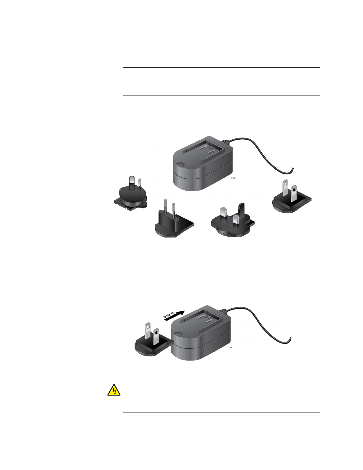
1. Ensure that the Multi-region AC/DC Power Adapter package contents
include one power adapter and one or more of the plugs shown in
Figure 37.
Figure 37. Package Contents
2. Remove the AC power plugs and power adapter from the shipping
package.
3. Select the AC power plug that is compatible with your region and slide
it into the power adapter as shown in Figure 38.
Figure 38. Slide AC Plug Into AC/DC Power Adapter
To prevent electric shock, slide the AC power plug into the AC/DC
power adapter before plugging it into the AC power wall receptacle.
5858
Page 59
FS710 Series Ehternet Switch Installation Guide
Note
Warning
Caution
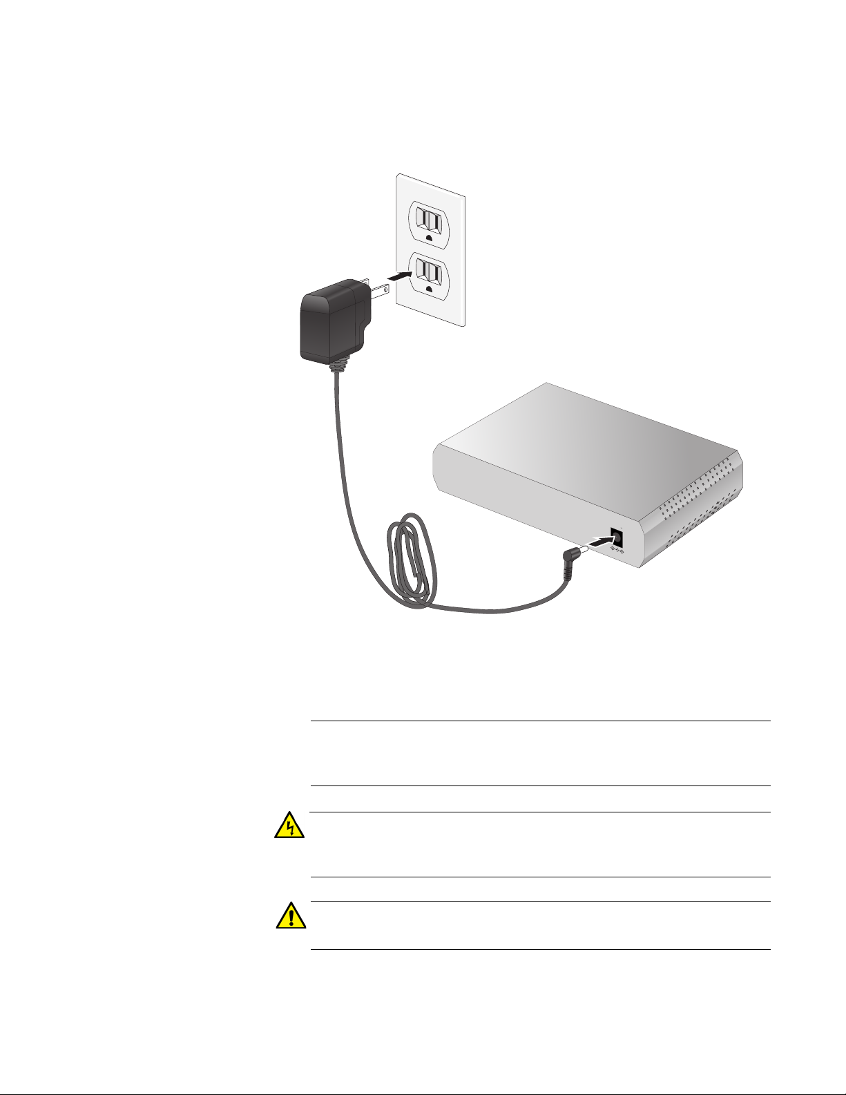
4. Insert the DC power plug into the DC power plug of your FS710 Series
switch and the AC power plug into the AC power wall receptacle as
shown in Figure 39.
.
4394
5VDC
–
4395
Figure 39. Plug Power Cord into Rear Panel DC Connector
5. Verify the PWR LED is green. If the LED is off, see Chapter 3,
“Troubleshooting” on page 61.
Allied Telesis recommends attaching the power cord to the switch
before plugging the power cord into a wall outlet.
Power cord is used as a disconnection device: To de-energize
equipment, disconnect the power cord. E3
Only use the AC adapter that is supplied with the unit. E85
6. Go to “Cabling the Switch” on page 60.
59
Page 60

Cabling the Switch
After installing the switch, connect twisted pair cables to the Ethernet
ports. When connecting a twisted pair cable, observe the following
guidelines:
The RJ-45 connector should fit snugly into the port on the switch.
The tab on the connector should lock the connector into place.
The ports on the switch are auto-MDI/MDI-X. You can use a
straight-through twisted pair cable to connect any type of network
device to a port on the switch.
The network should not contain data loops, which can adversely
affect network performance. A data loop exists when two or more
network devices can communicate with each other over more than
one data path.
Use cable ties (not provided) to dress and bundle the Ethernet cables as
the distance increases away from switch.
The switch is now ready for network operations.
6060
Page 61

Chapter 3
Note
Troubleshooting
This chapter contains information on how to troubleshoot the switch in the
event a problem occurs.
If you are still unable to resolve the problem after following the
instructions in this chapter, contact Allied Telesis Technical Support
for assistance. Refer to “Contacting Allied Telesis” on page 14.
Check the PWR LED on the front of the switch. If the LED is OFF,
indicating that the unit is not receiving power, do the following:
Verify that the power cord is securely connected to the power source
and to the connector on the back panel of the switch.
Verify that the AC power outlet or power adapter has power by
connecting another device to it.
Try connecting the power adapter to another power source.
Verify that the voltage from the power source is within the required
levels for your region.
Verify that the L/A LED for each port is green. If an L/A LED is OFF, do the
following:
Verify that the end-node connected to the port is powered ON and is
operating properly.
Verify that the twisted pair cable is securely connected to the port on
the switch and to the port on the end-node.
Ensure that the twisted pair cable does not exceed 100 meters (328
feet).
Verify that you are using the appropriate category of twisted pair cable:
Category 3 or better for 10 Mbps operation and Category 5 for 100
Mbps operation.
61
Page 62

Appendix A
Technical Specifications
This appendix contains the following sections:
”Physical Specifications”
“Environmental Specifications” on page 63
“Chassis Power Specifications” on page 63
“External Power Adapter Specifications” on page 63
“RJ-45 Twisted Pair Port Connectors” on page 64
Physical Specifications
Table 10. Physical Dimensions (W x D x H)
Specification Dimension (W x D x H)
FS710/5 & FS710/5E 130mm x 101mm x 30mm
FS710/8 & FS710/8E 195mm x 124mm x 38mm
FS710/16 & FS710/16E 210mm x 124mm x 44mm
FS710/24 305mm x 180mm x 44mm
Table 11. Product Weight
Model Weight
AT-FS710/5 0.4 Kg
AT-FS710/8 0.7 Kg
AT-FS710/16 0.9 Kg
AT-FS710/24 1.6 Kg
AT-FS710/5E 0.4 Kg
AT-FS710/8E 0.7 Kg
AT-FS710/16E 0.9 Kg
External AC Adapter 122.3 g
62
Page 63

Environmental Specifications
Table 12. Environmental Specifications
Specification Parameter
Operating Temperature 0° C to 50° C (32° F to 122° F)
Storage Temperature -25° C to 70° C (-13° F to 158° F)
Operating Humidity 5% to 90% non-condensing
Storage Humidity 5% to 95% non-condensing
Operating Altitude 2000 meters maximum
Chassis Power Specifications
Table 13. Chassis Input Power Specifications
FS710 Series Ehternet Switch Installation Guide
Model
AT-FS710/5 100 - 240 VAC, 0.20 A 50/60 Hz
AT-FS710/8 100 - 240 VAC, 0.20 A 50/60 Hz
AT-FS710/16 100 - 240 VAC, 0.22 A 50/60 Hz
AT-FS710/24 100 - 240 VAC, 0.22 A 50/60 Hz
AT-FS710/5E 5 VDC, 2 A N/A
AT-FS710/8E 5 VDC, 2 A N/A
AT-FS710/16E 5 VDC, 2 A N/A
Chassis Input Power
Ratings
External Power Adapter Specifications
Table 14. AC/DC Power Adapter Specifications
Specification Parameter
Rated Input Voltage 100 - 240 VAC
Frequency
Rated Input Frequency 50/60 Hz
Rated Input Current 0.4 A max
DC Output Voltage 5 V
Output Current 2 A
63
Page 64

RJ-45 Twisted Pair Port Connectors
This section lists the connectors and connector pinouts for the
AT-FS708 Fast Ethernet switch and its components.
Figure 40 illustrates the pin layout to an RJ-45 connector and port.
Figure 40. RJ-45 Connector and Port Pin Layout
Table 15 lists the RJ-45 pin signals when a twisted pair port is operating in
the MDI configuration.
Table 15. MDI Pin Signals (10Base-T or 100Base-TX)
FS710 Series Ehternet Switch Installation Guide
Pin Signal
1TX+
2TX-
3RX+
6RX-
Table 16 lists the RJ-45 port pin signals when a twisted pair port is
operating in the MDI-X configuration.
Table 16. MDI-X Pin Signals (10Base-T or 100Base-TX)
Pin Signal
1RX+
2RX-
3TX+
6TX-
64
 Loading...