


ALLEN&HEATH
GL4000
Dual Function Audio Mixing Console
USER GUIDE
PUBLICATION: AP2642

USER GUIDE
CONTENTS |
|
Warranty ............................................................... |
2 |
Introduction ........................................................... |
3 |
Overview .............................................................. |
4 |
Range and Options ............................................... |
5 |
Dimensions and Weights ...................................... |
6 |
Specifications ....................................................... |
7 |
System Block Diagram ......................................... |
8 |
Connectors ......................................................... |
10 |
Earthing .............................................................. |
13 |
Connecting the Power Unit ................................. |
14 |
Matching the Signal Levels ................................. |
15 |
Mono Input Channel ........................................... |
16 |
Stereo Input Channel .......................................... |
18 |
Stereo Channel Applications............................... |
19 |
Group Section .................................................... |
20 |
LR Section .......................................................... |
21 |
Mono and Master Section ................................... |
23 |
The Mute System ............................................... |
26 |
Mute Groups ....................................................... |
28 |
Mute Safes ......................................................... |
31 |
Mute Patches ..................................................... |
32 |
The Patch Display .............................................. |
33 |
QuickSolo ........................................................... |
36 |
Solo Safes .......................................................... |
37 |
MIDI .................................................................... |
38 |
Technical Support............................................... |
42 |
Front-of House Application ................................. |
44 |
On-Stage Monitor Application ............................. |
48 |
Multi-Speaker System Application ...................... |
51 |
Internal Link Options ........................................... |
52 |
Panel Layout Drawing ............................. |
rear cover |
copyright © 2001 ALLEN & HEATH. All rights reserved |
Publication ............. |
AP2642 Issue 3 |
1

LIMITED ONE YEAR WARRANTY
This product has been manufactured in the UK by ALLEN & HEATH and is warranted to be free from defects in materials or workmanship for a period of one year from the date of purchase by the original owner.
To ensure the high level of performance and reliability for which this equipment has been designed and manufactured please read this User Guide before use.
In the event of a failure notify and return the defective unit to
ALLEN & HEATH or its authorised agent as soon as possible for repair under warranty subject to the following conditions:
CONDITIONS OF WARRANTY
1.The equipment has been installed and operated in accordance with the instructions in the User Guide.
2.The equipment has not been subject to misuse either intended or accidental, neglect, or alteration other than as described in the User Guide or Service Manual, or approved by ALLEN & HEATH.
3.Any necessary adjustment, alteration, or repair has been made by ALLEN & HEATH or its authorised agent.
4.The defective unit is to be returned carriage prepaid to ALLEN & HEATH or its authorised agent with proof of purchase.
5.Units to be returned should be packed to avoid transit damage.
These terms of warranty apply to UK sales. In other territories the terms may vary according to legal requirements.
This product complies with the European Electromagnetic Compatibility Directives 89/336/EEC & 92/31/EEC and the European Low Voltage Directives 73/23/EEC & 93/68/EEC.
MANUFACTURED IN THE UNITED KINGDOM
Allen & Heath Limited.
Kernick Industrial Estate,
Penryn, Cornwall, TR10 9LU.
http://www.allen-heath.com
2

INTRODUCTION
The GL4000 continues ALLEN & HEATH’s commitment to provide high quality audio mixing consoles engineered to meet the exacting requirements of today’s audio business. It brings you the latest in high performance technology and offers the reassurance of over two decades of console manufacture and customer support.
This user guide presents a quick reference to the function and application of the GL4000. For further information on the basic principles of audio system engineering please refer to one of the specialist publications available from bookshops and audio equipment dealers.
Whilst we believe the information in this guide to be reliable we do not assume responsibility for inaccuracies. We also reserve the right to make changes in the interest of further product development.
SERVICE AND TECHNICAL SUPPORT
Under normal conditions the GL4000 does not require user maintenance or internal calibration. In certain cases it may be necessary to reconfigure internal option links. This and any service work required should be carried out by qualified service or engineering personnel only.
We are able to offer further product support through our worldwide network of approved dealers and service agents. To help us provide the most efficient service please keep a record of the console serial number, and date and place of purchase to be quoted in any communication regarding this product.
SAFETY WARNING
Mains electricity is dangerous and can kill. Mains voltage is present within the power supply unit provided with the console. Do not remove the power unit cover with mains connected. The correct mains voltage setting is indicated on the rear of the power unit. Check your mains wiring and earthing before switching on.
DO NOT REMOVE THE MAINS EARTH CONNECTION!
The console chassis is connected to mains earth to ensure your safety. Audio 0V connects to the console chassis internally. Should problems be encountered with ground loops operate the audio ground lift switches on connected equipment accordingly or disconnect the cable screens at one end. Refer to the section on 'EARTHING' later in this User Guide.
GENERAL PRECAUTIONS
POWER SUPPLY Use only the power unit specified for the console. Check the unit for correct AC mains voltage setting before switching on. Allow adequate space around the unit for ventilation.
CONNECTIONS Use audio connectors and cables only for their intended purpose. Do not connect any source of AC or DC power to the console audio connectors. Do not connect the output of power amplifiers directly to the console.
CLEANING Avoid the use of chemicals, abrasives and solvents. The control panel is best cleaned with a soft brush and dry lint-free cloth. To remove stubborn marks (such as chinagraph pencil) isopropyl alcohol may be used.
LUBRICATION The faders, switches and potentiometers are lubricated for life. The use of electrical lubricants on these parts is not recommended.
DIRT, DUST, SMOKE and MOISTURE Prevent damage to the moving parts, such as faders and potentiometers, and cosmetics by avoiding drinks spillage, tobacco ash, smoke, and exposure to rain and condensation. Protect from excessive dirt, dust, heat and vibration.
3

OVERVIEW
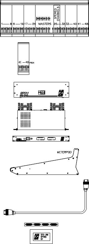
The GL4000 offers the professional user an uncompromised feature set and performance for live sound engineering and recording. The console is available in 24, 32, 40 and 48 channel sizes with an external 3U rack power unit. Options include bolt-on expander module, SYS-LINK interconnect system and 1U dual power supply monitor/combiner unit. Units from Serial Number 403421 include a built-in VU Meterpod as standard. An optional VU Meterpod is available for earlier units.
Dual function + live recording capability :
Large venue Front-of-House
Dedicated 12 buss (10mix+LR) stage monitor Dual function combines Front-of-House and monitor Live recording to 2-track and multitrack
24, 32, 40, 48 frame sizes including VU Meterpod Stereo models include mic/stereo line channels depending on customer specification
8 groups with inserts and trimmable balanced XLR outputs L,R,M mix on balanced XLR and with inserts
10 Aux sends on balanced XLR and with inserts
4 Matrix capable of balanced XLR and inserts
Matrix to aux link feature for group effects and monitors Secondary LR output capable of balanced XLR and inserts Channel Direct outputs with level trim and pre/post
4 band full sweep channel EQ with mid Q switches Stereo channel 4-point width control
Separate insert jacks with balanced returns MIDI mute system with 128 patches
8 independent mute groups Solo-in-place with QuickSolo feature
Full metering - channel, mix buss and outputs. Monitor with stereo PFL, local output, 2 phones ...
Simultaneous stereo and mono PFL metering Output meter selector switches for main or aux Talkback to L-R, M, groups, matrix, and to each aux 2-track replay to L-R and monitor
The console is constructed using extruded aluminium beams, steel panels and 3mm thick metal side plates to ensure rigidity and mechanical reliability on the road, as well as easy flightcasing. Individual circuit assemblies are accessible by removal of the steel base. A durable but soft front armrest is provided for comfort. Front, top and rear write-on strips are provided for channel marking. High quality proven reliable parts are used throughout. High performance op-amp and discrete circuits are used to ensure low noise and sonic purity.
The GL4000 reflects our commitment to providing the best audio mixing solutions and customer support.
4
THE RANGE
The following GL4000 models and options are available. For further details please contact your Allen & Heath agent :
GL4000-824 - 24 channel console
GL4000-832 - 32 channel console
GL4000-840 - 40 channel console
GL4000-848 - 48 channel console
The Stereo models can include mic/stereo line channels dependant on customer specification. The console is supplied with separate power supply, DC power cable and mains cable with moulded plug.
GL4000-8M - 8 mono channels expander
GL4000-4SM - 4 stereo, 4 mono expander
GL4000-4MS - 4 mono, 4 stereo expander
These expander modules are fitted by removing the console side plate, attaching to the chassis, and plugging in the harnesses. The console may beexpandedto amaximum of48channels.
RPS11 - 300W rack power unit with DC cable
RPSD2 - Dual supply combiner/monitor
1U 19" rack unit which allows two power units to connect to one console for redundant supply backup. Also provides local and remote DC rail LED monitoring.
The Integral Meterpod provides illuminated moving coil VU metering of the groups, L,R,M (or monitors, LR sidefill, listen wedge). Also additional PFL/AFL indicator.
GL4000-SL1 - SYS-LINK expander option
Circuitassemblyandmulti-pinconnectorsystem which can be fitted to the console to allow simple interconnection between two consoles so that one becomes the slave of the second by linking the audio busses and PFL/AFL system.
SYS-LINK interconnects using two standard 25way D-type cables to any other console fitted with the SYS-LINK system.
This option should be fitted only by your Allen & Heath agent or competent service personnel.
5
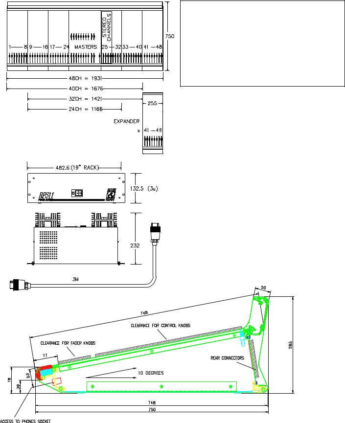
DIMENSIONS AND WEIGHTS
Dimensions shown in millimeters. |
UNPACKED |
Width |
Depth |
Height |
Wt (kg) |
|
|
|
|||||
|
GL4000M-824 |
1166 (46") |
748 (29.5") |
285 (11.2") |
47 |
(104lbs) |
|
GL4000M-832 |
1421 (56") |
748 (29.5") |
285 (11.2") |
57 |
(126lbs) |
|
GL4000M-840 |
1676 (66") |
748 (29.5") |
285 (11.2") |
67 |
(148lbs) |
|
GL4000M-848 |
1931 (76") |
748 (29.5") |
285 (11.2") |
77 (170lbs) |
|
|
GL4000-8M |
255 (10") |
748 (29.5") |
285 (11.2") |
9 (20lbs) |
|
|
RPS11 |
483 (19") |
232 (9.1") |
135 (3U) |
10 |
(22lbs) |
|
RPSD2 |
483 (19") |
180 (7.1") |
45 (1U) |
6 (13lbs) |
|
PACKED |
Width |
Depth |
Height |
Wt (kg) |
|
|
|||||
|
|
|
|
|
|
GL4000M-824 |
1702 (67") |
900 (35") |
390 (15.4") |
82 (181lbs) |
|
GL4000M-832 |
1702 |
(67") |
900 (35") |
390 (15.4") |
91 (201lbs) |
GL4000M-840 |
1950 |
(76.8") |
900 (35") |
390 (15.4") |
100 (221lbs) |
GL4000M-848 |
1931 |
(76") |
900 (35") |
390 (15.4") |
129 (284lbs) |
GL4000-8M |
480 (18.9") |
830 (32.7") |
260 (10.2") |
12 (26lbs) |
|
RPS11 |
575 (22.6") |
270 (10.6") |
170 (6.7") |
11 (24lbs) |
|
RPSD2 |
520 (20.5") |
260 (10.2") |
115 (4.5") |
6 (13lbs) |
|
|
|
|
|
|
|
6
SPECIFICATIONS
0dBu = 0.775 Vrms Reference for high level equipment +4dBu = 1.23 V 0dBV = 1 Vrms Reference for low level equipment -10dBV = 310 mV 0VU meter reading = +4dBu at XLR outputs
INPUT GAIN |
|
Mic/Line Input ................. |
+6dB to +60dB variable |
Mic/Line + Pad ............... |
-14dB to +40dB variable |
Line Input ....................... |
-14dB to +40dB variable |
Stereo Line Input ............ |
off to +10dB variable |
2-track Return ................ |
off to +10dB variable |
MAXIMUM OUTPUT LEVEL |
|
Main Outputs .................. |
+27dBu into load of >600 ohm |
Jack Outputs .................. |
+21dBu into load of >2K ohm |
Internal headroom .......... |
+21dB |
FREQUENCY RESPONSE
Measured 20Hz to 20kHz ref 1kHz
Mic to mix (+40dB) ......... |
+0/-0.5dB |
Line to mix (0dB) ............ |
+0/-0.5dB |
DISTORTION
THD + noise measured @ 1kHz +20dBu
Mic to mix (+40dB) ......... |
0.006% |
Line to mix (0dB) ............ |
0.006% |
CROSSTALK
Referred to driven channel @ 1kHz
Channel to channel ........ |
> 100dB |
Mute shutoff ................... |
> 85dB |
Fader shutoff .................. |
> 90dB |
NOISE PERFORMANCE |
|
Measured rms 22Hz to 22kHz bandwidth
Mic EIN........................... |
-128dB 150 ohm source |
|
Line pre-amp (0dB) ........ |
< -91dBu |
|
Residual output noise ......................... |
|
< -98dBu (-102dB S/N) |
Mix noise, nothing routed |
................... |
< -87dBu (-91dB S/N) |
Mix noise, 24 channels routed ............ |
< -81dBu (-85dB S/N) |
|
METERING |
|
|
Input meters ................... |
4 segment LED (signal, 0, +6, peak) |
|
Mix meters...................... |
4 segment LED (signal, 0, +6, peak) |
|
Output meters ................ |
12 segment LED |
|
LED meter response ...... |
peak reading |
|
Peak indicators ............... |
on 5dB before clipping |
|
Signal indicators ............. |
on -20dBu |
|
Meterpod ........................ |
Illuminated VU moving coil meters |
|
7
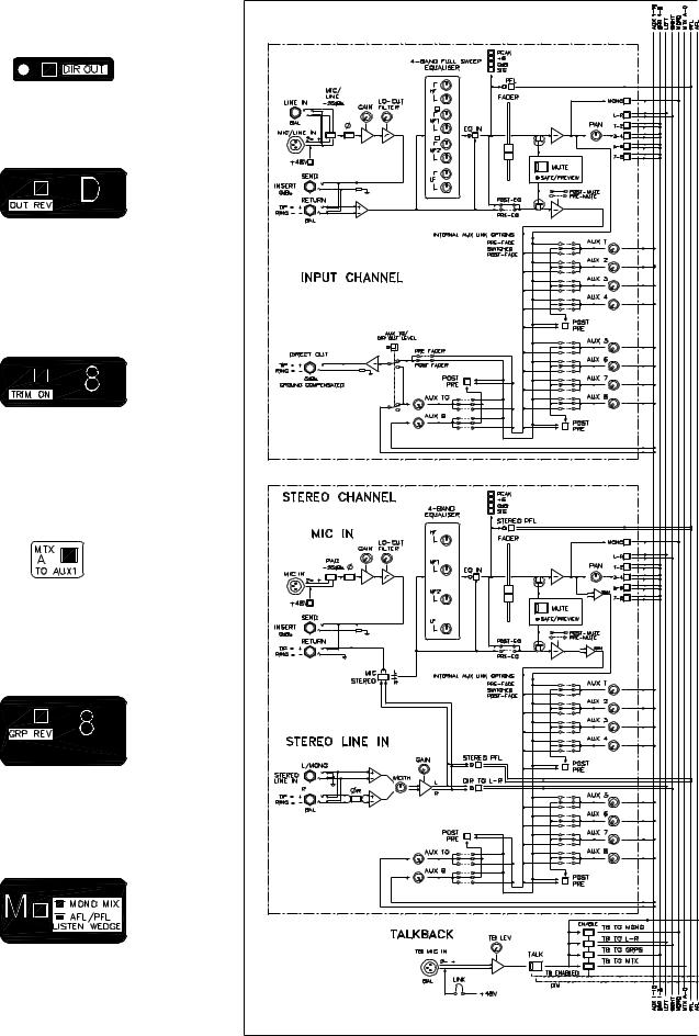
MODE SWITCHING
Protected underpanel mode switches set the console architecture according to the required application, for example FOH or stage monitor. Select these using a pointed object.
DIR OUT routes the channel direct out signal through the aux 10 pre/post selector and level control.
OUT REV swaps the matrix or LR2 output jack with the related aux XLR and insert. The control sections are not swapped. This can provide matrix outputs on XLR with inserts, or aux effects sends on jack as required.
TRIM ON routes the group output signal through a pre/post fader selector and level trim. This lets you record the groups independent of the subgrouping to LR and M.
MTX TO AUX Links the matrix mix into the aux mix to include aux sends from the groups, LR and M. Used for effects from the groups, and for quick monitor mixes.
GRP REV reverses the aux (small fader) and group (main fader) control sections. Also applies to LR. The outputs remain unaffected.
This mode is used for stage monitoring.
MONO MODE converts the mono output to the monitor engineers listen wedge. M AFL is disabled. The M mix still feeds the insert and matrix.
8

SYSTEM DIAGRAM
9
CONNECTORS
Professional gold plated connector types are used to ensure continued reliable operation. All the console main inputs and outputs are balanced XLRs. All 1/4" jacks are 3-pole TRS for operation with balanced or unbalanced equipment. Inserts are provided on all channel inputs, and on Groups, L, R, Mono and all Aux outputs. Aux can be swapped with matrix and LR2 for XLR outputs with inserts
DIRECT OUTPUT
Provides a buffered signal from the channel, ideal for minimum signal path connection to multitrack recorders or local effects sends. Set post-fader, post-mute as standard. Can be switched through the Aux10 send control for pre/post fader selection and level trim with +6dB maximum boost.
3-pole 1/4" jack socket (tip = hot). Impedance balanced 50 ohm 0dBulinelevelforconnectiontobalancedorunbalancedequipment.
INSERT SEND
Used to send the channel signal to external effects and signal processing equipment, post-pre-amp and pre-EQ.
3-pole 1/4" jack socket (tip = hot). Impedance balanced 0dBu 50ohm line level.
INSERT RETURN
Used to return the processed signal from external equipment into the channel audio signal path pre-EQ.
3-pole 1/4" jack socket (tip = hot). Balanced >10kohm 0dBu line level. (Stereo channel returns are unbalanced).
MIC/LINE INPUT
3-pin female XLR (pin 2 = hot). Electronically balanced. 74dB gain range. Mic impedance >2kohm, line >10kohm
Can be used for XLR line input when the LINE IN jack is left unplugged.
MONO CHANNEL LINE INPUT
3-pole 1/4" jack socket (tip = hot). Electronically balanced >10kohm.
STEREO CHANNEL LINE INPUT
3-pole 1/4" jack socket (tip = hot). Electronically balanced >10kohm. Plug into the Left input only for a mono line source.
10
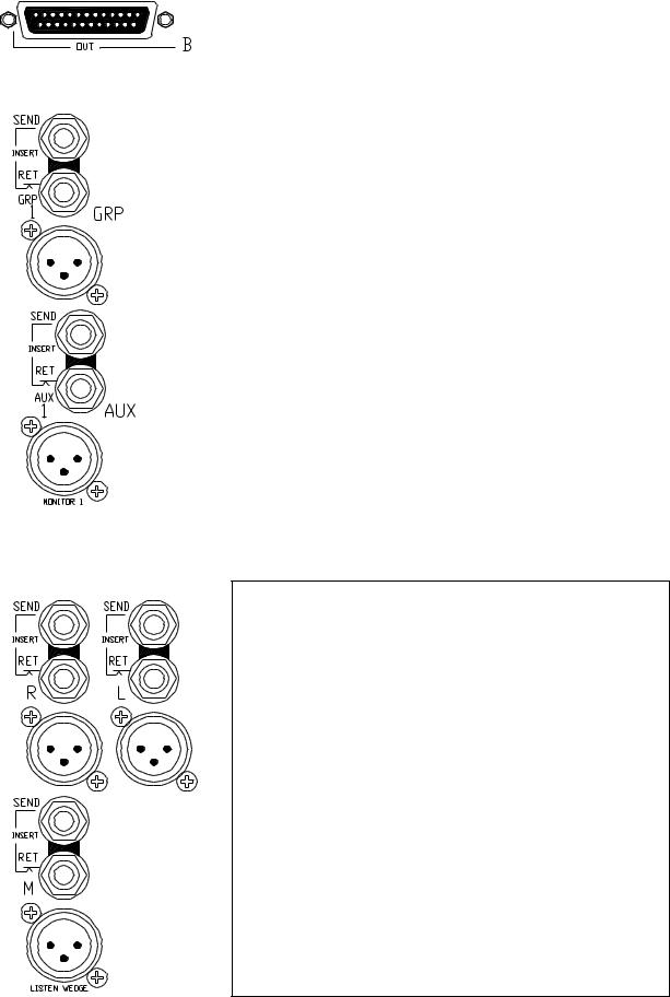
SYS-LINK EXPANDER OPTION
Available as a kit to be fitted to the console to expand the busses. Uses 4 25-pin D-type connectors (input and output A and B). Operates at -2dBu line level. Refer to your Allen & Heath agent for further details.
GROUP/AUX/L/R/M INSERT SEND
Used to send the output signal to external effects and signal processing equipment such as graphic equalisers, delays and compressors, post-mix amp and pre-fader.
3-pole 1/4" jack socket (tip = hot). Impedance balanced -2dBu 50ohm line level.
GROUP/AUX/L/R/M INSERT RETURN
Used to return the processed signal from external equipment into the output audio signal path pre-fader and mix meter.
3-pole 1/4" jack socket (tip = hot). Balanced >10kohm -2dBu line level.
GROUP/AUX/L/R/M MAIN OUTPUT
3-pin male XLR (pin 2 = hot). Electronically balanced 75ohm. +4dBu line level, +27dBu maximum into 600 ohm load.
Capable of driving long cable runs without loss or interference.
MODE SWITCHING
Set the underpanel mode switches for the intended console operation. Some of these affect the way the connectors work. For full details please refer to the BLOCK DIAGRAM.
OUT REV underpanel mode switch - The Aux XLRs and inserts can swap with the Matrix and LR2 output jacks for aux (effects) sends on jacks if required. This also provides matrix and LR2 outputs on XLRs with inserts for driving speaker systems.
MONO MODE underpanel mode switch - The Mono output becomes the engineers listen wedge monitor feed when the console is operated in on-stage monitor mode. However, the Mono insert remains with the mono mix.
MIX/AUX REV underpanel mode switch - Note that while the front panel control sections are swapped when the reverse mode switches are pressed, the signals always appear at their related connectors, ie. the connectors do not swap.
11
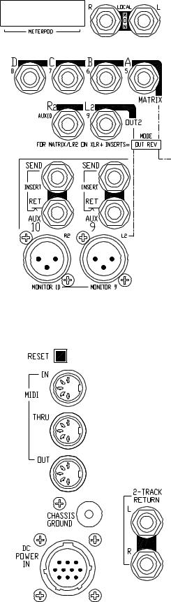
METERPOD CONNECTOR
Recessed 16-pin dual row header for connection to the meterpod.
LOCAL STEREO MONITOR
For connection to a stereo amplifier/speaker system for LR, AFL/ PFL monitoring local to the console.
3-pole 1/4" jack sockets (tip = hot). Impedance matched 50ohm 0dBu nominal line level.
HEADPHONES
Connections for 2 stereo headphones >8ohms. One connector is on the front panel, the other is concealed under the armrest.
3-pole 1/4" jack sockets (tip = left, ring = right).
MATRIX OUTPUT
3-pole 1/4" jack socket (tip = hot). Impedance balanced 50ohm 0dBu nominal line level.
Can swap with the aux output XLRs and inserts to drive long cable runs without loss or interference, and to insert external signal processing devices such as graphic equalisers and delays.
LR2 OUTPUT
Secondary LR output for 2-track recording, broadcast or additional speaker and zone feeds.
3-pole 1/4" jack socket (tip = hot). Impedance balanced 50ohm 0dBu nominal line level.
Can swap with the aux output XLRs and inserts to drive long cable runs without loss or interference, and to insert external signal processing devices such as graphic equalisers and delays.
2-TRACK RETURN INPUT
For connection to 2-track playback equipment such as cassette, DAT or CD players.
3-pole 1/4" jack sockets (tip = signal). Unbalanced 50ohm. +10dB maximum gain allows connection to low and high level equipment.
MIDI INTERFACE
Standard 5-pin 180' connectors for opto-isolated connection to other MIDI equipment. A mute processor reset switch is provided.
CONSOLE DC POWER INPUT
The console connects to a separate power supply unit via a 10-pin circular connector cable. Connect only the Allen & Heath power unit supplied with the console.
A chassis ground terminal post is provided. This connects to mains earth through the power cable.
12

EARTHING
The connection to earth (ground) in an audio system is important for two reasons:
1. SAFETY - To protect the operator from high voltage shock associated with the AC mains supply feeding the system, and
2.AUDIO PERFORMANCE QUALITY - To minimise the effect of earth (ground) loops which result in audible hum and buzz, and to shield the audio signals from external interference.
For safety it is important that all equipment earths are connected to mains earth so that exposed metal parts are prevented from carrying high voltage which can injure or even kill the operator. A solid, low impedance earth system is necessary to ensure that earths at different points in the system are kept at the same potential. A typical sound system includes amplifiers, signal processing equipment, microphones, musical instruments and much more in addition to the console, all of which require earth connection for safety and correctaudiooperation. Oftenthisequipmentisspreadacrossthevenueandinterconnected by hundreds of metres of power and audio cables. It is recommended that the sound engineer check the continuity of the safety earth from all points in the system including microphone bodies, guitar strings, muticore cases, equipment panels ...
The same earth is also used to shield audio cables from external interference such as the hum fields associated with power transformers, lighting dimmer buzz, and computer radiation. Earth is also used for the signal 'return' when connecting to unbalanced equipment. Problems arise when the signal sees more than one path to mains earth. An 'earth loop' (ground loop) results causing current to flow between the different earth paths. A larger potential difference between these paths results in more current flow and so more audible noise. This condition is usually detected as a low frequency hum or buzz at mains frequency or its harmonics.
To ensure operator safety and trouble-free audio performance from your system we recommend the following :
Do not remove the earth connection from the power unit mains plug. The console chassis is connected to mains earth through the power cable to ensure your safety. Audio 0V is connected to the console chassis internally. If problems are encountered with earth loops operate the audio 'ground lift' switches on connected equipment accordingly, or disconnect the cable screens at one end, usually at the destination. It is useful to carry ground lift cable adaptors such as short XLR male to female leads with pin1 disconnected.
Use a separate 'clean' mains outlet for the audio equipment to prevent interference from other equipment such as lighting, stage machinery and vending machines. Ensure a good central 'star point' earth connection.
Avoid running audio cables next to mains, computer or lighting cables, or near thyristor dimmer and power supply units. If unavoidable, cross these at right angles.
Use low impedance sources such as 200 ohm or less microphones to reduce susceptability to interference. The console outputs are designed to operate at very low impedance to minimise interference problems.
Use balanced connections where possible as these provide further immunity by cancelling out interference that may be picked up on long cable runs. To connect an unbalanced source to a balanced console input, link the cold input (XLR pin3 or jack ring) to 0V earth (XLR pin1 or jack sleeve) at the console. To connect a balanced console output to an unbalanced destination, link the cold output to 0V earth at the console.
Use professional quality cables and connectors and check for correct wiring and reliable solder joints.
If you are not sure ... Have your system checked by a competent engineer, or contact your local Allen & Heath agent for advice.
13
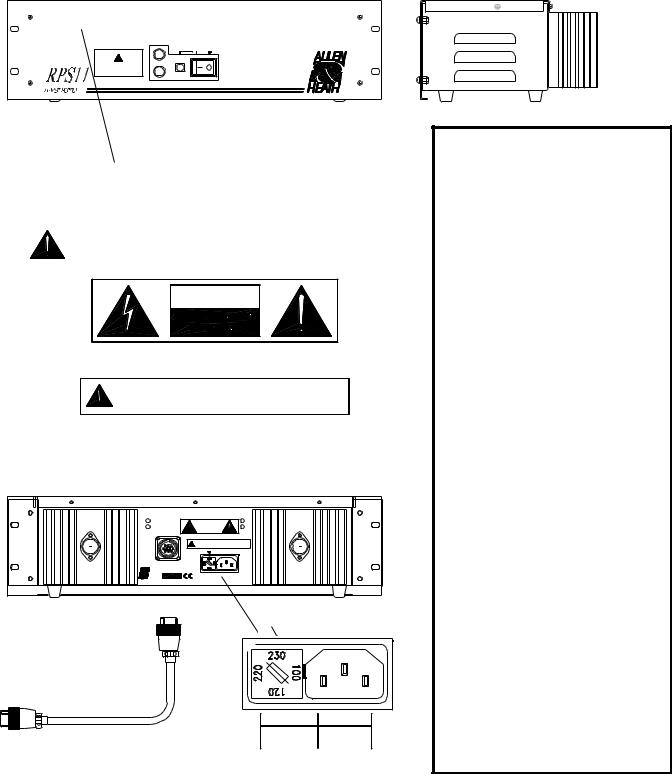
CONNECTING THE POWER UNIT
Connect only the Allen & Heath power unit specified for the console. The standard unit for GL4000 is the RPS11. This is an external 3U 19" rack mounted unit that connects to the console via the separate DC cable supplied. The RPS11 is a low noise linear design that converts AC mains voltage to the DC voltages required to power the console. It also provides +48V phantom power for use with high quality powered microphones. The presence of AC mains voltage is shown on the power unit front panel neon indicator. The presence of the DC voltages is shown on the console power indicator LEDs. A second backup RPS11 may be connected to the console through the optional RPSD-2 dual supply combiner unit available from your Allen & Heath agent if required.
DO NOT OBSTRUCT VENTILATION OPENINGS. ALLOW ADEQUATE VENTILATION AROUND THE UNIT.
SEE INSTALLATION INSTRUCTIONS BEFORE CONNECTING TO THE SUPPLY.
DC FUSES
CAUTION: FOR CONTINUED PROTECTION AGAINST RISK OF FIRE
REPLACE FUSE WITH SAME TYPE AND RATING.
ATTENTION: REMPLACER LE FUSIBLE AVEC UN DES MEMES
CARACTE RISTIQUES.
T 10A 250V 20mm
ON OFF
V+
V-
DO NOT OBSTRUCT VENTILATION OPENINGS.
ALLOW ADEQUATE VENTILATION AROUND THE UNIT.
WARNING - THIS APPARATUS MUST BE EARTHED.
WARNING: TO REDUCE THE RISK OF ELECTRIC SHOCK, DO NOT EXPOSE THIS APPARATUS TO RAIN OR MOISTURE
CAUTION
AVIS: RISQUE DE CHOC ELECTRIQUE - NE PAS OUVRIR.
CAUTION: FOR CONTINUED PROTECTION AGAINST RISK OF FIRE REPLACE FUSE
WITH SAME TYPE AND RATING.
ATTENTION: REMPLACER LE FUSIBLE AVEC UN DES MEMES CARACTERISTIQUES.
NO USER SERVICEABLE PARTS INSIDE
SERIAL No:
 AC MAINS IN ~
47-63Hz |
FUSE TYPE |
AC SUPPLY |
320VA MAX |
T 3.15A 20mm |
220 - 240V~ |
300W MAX |
T 5.0A 20mm |
100 - 120V~ |
SAFETY WARNINGS !
Ensure that the warnings printed on the power unit (shown here) are followed.
Always switch the power unit off before connecting or disconnecting the console power cable.
Itisnormalforthepowerunittodissipate heat. Do not cover the unit or position it on soft furnishings during operation. Do not position other equipment known to generate significant amounts of heat below the unit. It is recommended that rack units containing high power amplifiers and other heat dissipating equipment are fitted with cooling fans.
BEFORE SWITCHING ON !
Check that the voltage indicated on the fuseholder is correct for the mains voltage in your area.
Check that the mains IEC connector is fully inserted into the inlet socket.
Check that the DC power cable is correctly fitted to both the power unit and the console. The locking ring should be screwed in place.
It is recommended that audio power amplifiers are switched on last and switched off first to prevent possible damage to loudspeakers.
Check the system for safety earthing.
14
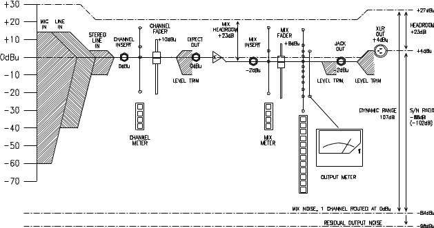
MATCHING THE SIGNAL LEVELS
For best performance it is important that the connected source signals are matched to the "normal operating level" of the console. Similarly the console outputs should be correctly matched to the operating levels of the connected amplifiers and destination equipment. If too high the signal peaks will be clipped resulting in a harsh distorted sound, and if too low the signal-to-noise ratio is reduced resulting in excessive background hiss and noise.
For best results operate the console with the meters averaging around '0' letting the louder passages peak into the 'yellow'. Reduce the gain if the red peak indicators flash. The GL4000 produces a standard XLR output level of +4dBu for a meter reading of 0VU. It is advisable to adjust the power amplifier input gain or fit an attenuator pad if normal console operation results in an output level too high for the connected amplifier. Normal operation should result in fader levels around the '0' mark. Note that when reversed with the auxes the matrix and LR2 output level trims can be used to match the console to the amplifiers independent of the mix levels. Similarly the group output trims can be switched in to match levels.
The GL4000 has an advanced PFL (pre-fade listen) / AFL (after-fader listen) and channel metering system to let you listen to and check the level of signals at different points in the signal path without affecting the main outputs. Use the channel PFL switches to set up the input GAIN controls to read an average '0'. Signal activity is always shown on the channel meters regardless of fader position. The green 'SIG' LED lights at -20dBu to indicate signal presence, the green '0' LED indicates normal level, yellow '+6' indicates normal peaks, and the red 'PEAK' LED warns of potential overload 5dB before clipping.
The mix meters above each output fader monitors the pre-fade mix level. You can run the mix 'hot' but reduce the channel fader levels if the red 'PEAK' LEDs flash.
LEVEL DIAGRAM
15
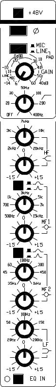
MONO INPUT
+48V - Feeds +48V to pins 2 and 3 of the input XLR for condenser microphones which require phantom power.
Plug the microphone in before switching +48V on or off. Use +48V |
( |
||
only with balanced microphones and cables. No damage will occur |
|||
when +48V is switched to balanced non-phantom powered transformer |
|
||
coupled dynamic microphones. However, always switch +48V off when |
|
||
connecting line or unbalanced sources. |
|
||
PHASE REVERSE - |
Reverses XLR input pins 2 and 3 to correct for |
|
|
reverse wired cables or reversed phase signals. Can also be effective in |
|
||
minimising acoustic feedback between the microphone and loudspeakers |
|
||
in live sound mixing. |
|
|
|
MIC/LINE(PAD) - Selectslineinputsensitivity whenpressed,microphone |
|
||
when released. Note that with the line jack unplugged the switch acts as |
|
||
a 20dB pad for high output microphones or line input on XLR. |
|
||
GAIN - Use this control with the MIC/LINE switch to adjust the channel |
|
||
input sensitivity to match the connected source (-60 to +14dBu) to the |
|
||
console operating level (0dBu). The gain should be set so that the channel |
|
||
meter reads an average '0'. |
|
||
LO-CUT FILTER |
- |
Reduces low frequency source noise such as |
|
microphone proximity popping, stage noise and transport rumble. Can be |
|
||
used to clean up sounds that do not have much bass content such as |
|
||
vocals (around 150Hz), separate out the top end of a drum kit (400Hz), |
|
||
reduce the handling noise of acoustic instruments, and so on. Select the |
|
||
required cut off frequency by sweeping from fully anticlockwise (filter off) |
|
||
to the maximum 400Hz. Setting the cutoff to 50Hz will have little effect on |
|
||
most program material but will protect the low frequency speaker drivers. |
|
||
The response drops by 12dB per octave below the cut off frequency. |
|
||
EQUALISER - |
This provides separate, simultaneous control of 4 |
|
|
frequency bands. Each band may be boosted or cut by up to +/- 15dB centred on the selected frequency which may be swept across a wide range. Use the equaliser to correct for tonal deficiencies in the source such as acoustic resonances or poor microphone response (corrective EQ), or to change the tonal balance, for example to brighten up a guitar so it cuts through the mix (effective EQ). You may need to adjust the input GAIN control when using excessive amounts of EQ to compensate for the change in overall signal level.
HF and LF affect the high (treble) and low (bass) frequencies respectively. These have a shelving response which means that all frequencies beyond the selected frequency are affected.
MF1 and MF2 affect the upper and lower mid frequencies respectively. These have a peak/dip (bell shaped) response which means that the maximum boost or cut occurs at the selected (center) frequency. The MF1 and MF2 bands overlap for additional cut or boost when required or to provide a tailored frequency response to suit any application. The sharpness of the curve is selected using the Q switch to a Q of either 1 (wide band) or 2.4 (narrow band). Use wide band when you want to add presence or warmth to the sound. Use narrow band to control problem frequencies for example when notching out acoustic resonances.
16
 Loading...