


DR66

INSTALLER USER GUIDE
Publication AP4333
Digital Audio Mix Processors
DR66 & DR128
2 DR66 & DR128 Installer User Guide
DR66 & DR128 Installer User Guide AP4333 Issue 3.
Copyright © 2001 Allen & Heath Limited. All rights reserved
Whilst we believe the information in this guide to be reliable we do not assume
responsibility for inaccuracies. We also reserve the right to make changes in
the interest of further product development.
This product complies with the European Electromagnetic
Compatibility directives 89/336/EEC & 92/31/EEC and the
European Low Voltage Directives 73/23/EEC & 93/68/EEC.
NOTE: Any changes or modifications to the equipment not approved by Allen
& Heath could void the compliance of the console and therefore the users
authority to operate it.
Manufactured in the United Kingdom by
Allen & Heath Limited
Kernick Industrial Estate, Penryn, Cornwall, TR10 9LU, UK
http://www.allen-heath.com
Limited One Year Warranty
This product has been manufactured in the UK by ALLEN & HEATH and is
warranted to be free from defects in materials or workmanship for period of one
year from the date of purchase by the original owner.
To ensure a high level of performance and reliability for which this equipment has
been designed and manufactured, read this User Guide before operating.
In the event of a failure, notify and return the defective unit to ALLEN & HEATH or
its authorised agent as soon as possible for repair under warranty subject to the
following conditions:
Conditions Of Warranty
1. The equipment has been installed and operated in accordance with the
instructions in this User Guide
2. The equipment has not been subject to misuse either intended or accidental,
neglect, or alteration other than as described in the User Guide or Service
Manual, or approved by ALLEN & HEATH.
3. Any necessary adjustment, alteration or repair has been carried out by ALLEN
& HEATH or its authorised agent.
4. The defective unit is to be returned carriage prepaid to ALLEN & HEATH or its
authorised agent with proof of purchase.
5. Units returned should be packed to avoid transit damage.
In certain territories the terms may vary. Check with your ALLEN & HEATH agent
for any additional warranty, which may apply.

DR66 & DR128 Installer User Guide 3
Introduction
This user guide refers to the Allen & Heath DR128 and DR66 digital mix processors loaded with
Version 2 or later operating software. Units loaded with earlier versions can be updated to take
advantage of the features available from Version 2. Further information and the software itself can
be downloaded from our Web site: http://www.allen-heath.com
This guide is intended for the technical engineer in charge of the installation and configuration of
the audio system. It is not intended for the day-to-day user who should be provided with operating
instructions specific to the application by the installer. The function, application, installation and
technical details of the DR hardware are described. For details on the configuration of the DSP
resources please refer to the Windows
®
Help file in the PC WinDR System Manager software
provided with the unit.
We are able to offer further product support through our worldwide network of approved dealers
and service agents. You can also access our Web site on the Internet for information on our full
product range, distribution network and technical support. To help us provide the most efficient
service please keep a record of the serial number and purchase details to be quoted in any
communication regarding this product. The serial number is located on the rear panel.
Contents
Warranty and Contact Details ............ Inside Front
Important Safety Instructions ............................... 4
Mains Voltage Setting and Plug Wiring ............... 5
Welcome to the DR Series .................................. 6
Main Features ...................................................... 7
System Block Diagram ........................................ 8
Basic Principles ................................................... 9
Front Panel ........................................................ 10
Rear Panel ......................................................... 12
Installation.......................................................... 14
Connecting Power Supplies .............................. 15
Earthing.............................................................. 16
Configuring the Hardware.................................. 17
Starting with the Default Configuration.............. 17
Starting with WinDR........................................... 17
Calibration Adjustments available ..................... 18
Removing the Top Cover................................... 18
Labelling the Function Keys .............................. 19
Working with Audio Signals ............................... 19
Calibrating the XLR Mic/Line Inputs .................. 20
Calibrating the RCA Phono Line Inputs ............ 21
Calibrating the XLR Line Outputs...................... 22
Remote Switch Wiring ....................................... 23
Remote Output Wiring ....................................... 24
Fitting the DSPx Expander Option .................... 25
Fitting the DSPd Delay Option .......................... 25
Configuring the Software ................................... 26
Software Compatibility Issues ........................... 26
Installing the WinDR System Manager ............. 27
Using WinDR ..................................................... 28
Configuring Control............................................ 29
Networked Computer System............................ 29
SysNet................................................................ 29
Using the DR...................................................... 30
The Front Panel LCD Display............................ 30
The Function Keys............................................. 31
The Function LEDs ............................................ 33
The Setup Keys ................................................. 34
Adjusting LCD Contrast ..................................... 35
Adjusting Clock Time ......................................... 35
Adjusting Day of Week ...................................... 35
Appendix A : Earlier Version 1 Software ........... 36
Appendix B : Technical Specification ................ 39
Appendix C : DR66 Architects Specification ..... 40
Appendix D : DR128 Architects Specification... 41
Installation Log Sheet ........................................ 42
DR128 Front Panel Label Template .................. 43
4 DR66 & DR128 Installer User Guide
Important Safety Instructions
WARNINGS - Read the following before proceeding:
ATTENTION: RISQUE DE CHOC ELECTRIQUE – NE PAS OUVRIR
Read instructions: Retain these safety and operating instructions for future reference. Heed all
warnings printed here and on the equipment. Ensure that the operating
instructions printed in this user guide are adhered to.
Removing the cover: Operate the unit with its top cover correctly fitted. Do not touch or tamper with
the internal power supply circuits while configuring or adjusting the internal
settings with power applied. Do not remove the internal power unit protection
cover at any time.
Power sources: Connect the unit to a mains power source only of the type described in this User
Guide and marked on the rear panel. Use the power cord with sealed mains plug
appropriate to your local mains supply as provided with the console. If the
provided plug does not fit into your outlet consult your agent for assistance.
Power cord routing: Route the power cord so that it is not likely to be walked on, stretched or pinched
by items placed upon or against it.
Grounding: Do not defeat the grounding and polarisation means of the power cord plug. Do
not remove or tamper with the ground connection in the power cord.
Water and moisture: To reduce the risk of fire or electric shock do not expose the unit to rain or
moisture or use it in damp or wet conditions. Do not place containers of liquids
on it that might spill into any openings.
Ventilation: Do not obstruct the ventilation slots or position the unit where the airflow required
for ventilation is impeded. If the unit is to be operated in a rack or other furniture
ensure that it is constructed to allow adequate ventilation.
Heat and vibration: Do not locate the unit in a place subject to excessive heat or direct sunlight, as
this could be a fire hazard. Locate the unit away from any equipment that
produces heat or causes excessive vibration.
Servicing: Switch off the equipment and unplug the power cord immediately if it is exposed
to moisture, spilled liquid, objects fallen into the openings, the power cord or plug
become damaged, during lightening storms, or if smoke, odour or noise is
noticed. Refer servicing to qualified technical personnel only.
Installation: Install the unit in accordance with the instructions printed in this User Guide.
Unauthorised changes or modifications may invalidate the warranty or legal
compliance of the unit and could void the user’s authority to operate it.
CAUTION
WARNING: This equipment must be earthed.
WARNING: This equipment must be installed
and configured by competent technical personnel only.
DR66 & DR128 Installer User Guide 5
The Mains Voltage Setting
Before starting check that the mains voltage setting on the DR unit is correctly
set for the local mains supply. Check that the correct mains lead with
moulded mains plug and IEC connector has been supplied with your unit.
Read and understand the warnings and instructions printed on the facing
page and on the rear panel.
It is advised to turn connected power amplifiers down or off before switching
the DR unit on or off. Ensure that the IEC mains plug is pressed fully into the
rear panel socket before switching on.
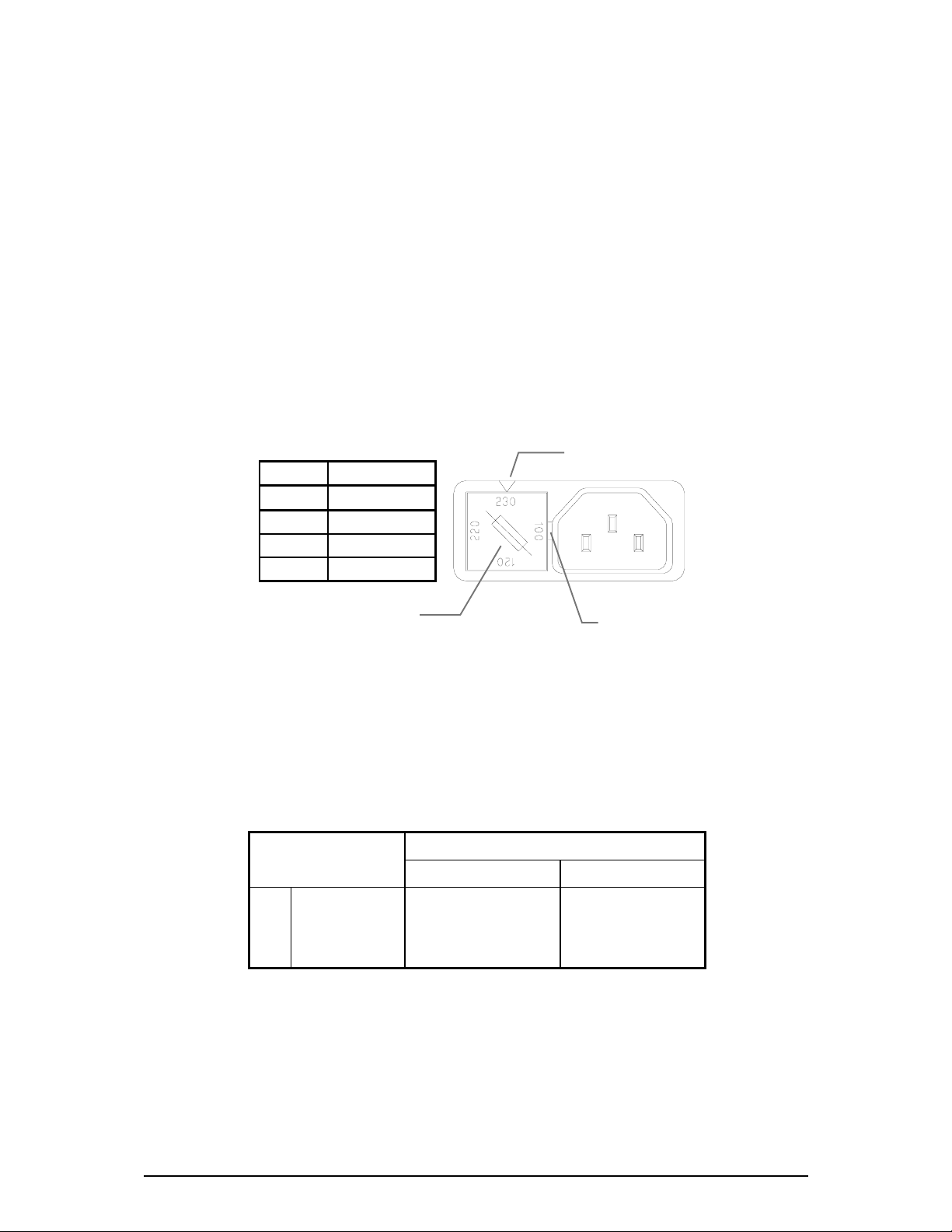
Changing the Fuse or Mains Voltage Setting
The unit may be configured for the following mains voltages. The rear panel
mains protection fuse is a standard 20mm anti-surge type. Use the correct
fuse type and rating for the selected mains voltage as shown.
To change the mains fuse first unplug the mains lead from the rear of the unit.
Remove the fuse cover from the AC inlet socket using a small flat bladed
screwdriver. To change the mains voltage settings replace the fuse cover as
indicated on the fuse cover - with the correct mains setting pointing upwards.
Important Mains Plug Wiring Instructions.
The power unit is supplied with a moulded mains plug fitted to the AC mains
power lead. Follow the instructions below if the mains plug has to be
replaced. The mains lead wires are coloured in accordance with the following
code. Ensure that these colour codes are followed carefully in the event of
the plug being changed.
WIRE COLOUR
TERMINAL
European USA/Canada
L LIVE BROWN BLACK
N NEUTRAL BLUE WHITE
E EARTH GND GREEN & YELLOW GREEN
The wire which is coloured Green/Yellow must be connected to the terminal in
the plug that is marked with the letter E or with the Earth symbol. This
appliance must be earthed.
The wire which is coloured Blue must be connected to the terminal in the plug
which is marked with the letter N.
The wire which is coloured Brown must be connected to the terminal in the
plug which is marked with the letter L.
Ac mains Fuse
100V AC 20mm T1.6A
120V AC 20mm T1.6A
220V AC 20mm T630mA
230V AC 20mm T630mA
Lever cover out with
flat bladed screwdriver
Fuse Cover
Setting

6 DR66 & DR128 Installer User Guide
Welcome to the DR Series
DR66 6 In 6 Out Digital Audio Mix Processor
DR128 12 In 8 Out Digital Audio Mix Processor
The DR66 and DR128 are part of the Allen & Heath Contractor Series designed for installed sound
such as public announcement, conference and background music systems in hotels, restaurants,
government buildings, sports and leisure facilities and so on. They offer the same audio
architecture, programmability and processing capability, use the same operating system, but differ
in size and the number of inputs and outputs available. The powerful and expandable internal DSP
(digital signal processor) enables sophisticated installation setups requiring full matrix mixing,
zoning, signal processing and network control in a compact 1 or 2U rack space.
Also available for the DR are the DSPx resource expander and the DSPd output delay option
cards. Other products in the Contractor Series include the GR05 and GR1 analog zone mixers
and the GR8A 8-channel amplifier together with its GR8X transformer option for 70/100V
speakers.
WinDR System Manager
The Allen & Heath WinDR System Manager is a Microsoft Windows
®
application that runs on a PC
such as laptop, desk or networked system. It is provided with the unit for the installer to configure
the internal routing and signal processing according to the requirements of the installation. Once
configured, the DR runs as a stand-alone system without the need to have the PC connected. The
front panel and remote switches can be assigned by the installer to provide the operator with the
limited control required for day to day operation whilst tamper proofing the system settings.
Note: This user guide refers to DR units loaded with Version 2 or later operating software. If
you are configuring the unit to match a previous installation running version 1.8 software you can
load in the earlier version by downloading it from the Allen & Heath Web site. Loading instructions
and details on the release history of the software are available from the site. Instructions on using
the WinDR application and configuring the DR are available from the Help file within the software.

DR66 & DR128 Installer User Guide 7
Main Features DR66 DR128
• Desktop or 19” rack mount 1U 2U
Removable rack ears and feet for rack, plinth or freestanding operation.
• Balanced XLR Mic/Line inputs 2 8
Built in preamp stage for directly plugging in microphones and line
equipment. Internal links for phantom power and rear panel gain trimmers.
• Unbalanced dual RCA phono Line inputs 4 4
Sums L+R to convert the stereo source for typical mono zoning application.
Internal trim to match connected source.
• Balanced XLR outputs 6 8
With internal level trim. Capable of driving long cable runs to the amps.
• Opto-isolated remote inputs 12 8
Ideal for remote wall plate switch control of levels and patch selection.
• Opto-isolated remote outputs 4 0
For remote LED/lamp display, or switching of relays and other equipment.
• Installer assignable front panel keys 8 12
For day-to-day operator control of levels and pre-determined patch selection.
• Routing matrix with crosspoint level control 6x6 12x8
Independently adjusts the level of any input to any output.
• Front panel LCD display
Displays active patch number, name, day, time, level and other information.
• Mains and battery backup power input
24V battery input for power backup.
• RS232 com port
For configuration by PC, gateway for network control, or communication with
industry standard remote controllers using the Allen & Heath SysNet protocol.
• WinDR System Manager software …
For flexible system configuration to satisfy exact install requirements.
• Up to 99 internal configuration patches
For full or partial parameter changes with single key, remote or timed actions
for day to day operations such as source selection, paging, room combining,
alarm management, event configurations, and so on.
• Real time clock
For time and day of week scheduled patch events
• Channel and patch naming
Name input, output channels and patches with up to 8 characters each.
• Protection limiters on all outputs
With full parameter control to protect speakers and destination equipment.
• Ducker with multiple priority levels
For voiceover, jukebox and other auto level functions.
• Automatic mic mixing with ambient level sensing
Adjusts the output level according to the number of open mics and level of
background noise.
• Level, mute and polarity control
Independently available for every input and output channel.
• Assignable signal processing resources
31/15/7 band graphic, 6/4/2 band Parametric EQ, Noise gates, Compressors.
Internally expandable for more DSP power and/or output delay function.
8 DR66 & DR128 Installer User Guide
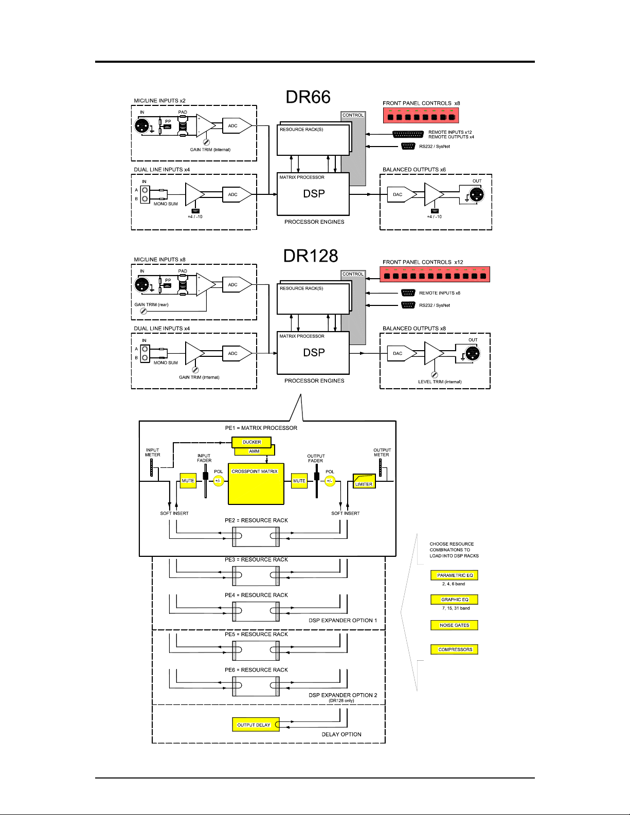
System Block Diagram

DR66 & DR128 Installer User Guide 9
Basic Principles
Audio Inputs and Outputs
The DR66 and DR128 audio mix processors accept any level of microphone or line level input
signals. These are pre-amplified and adjusted to the correct internal operating level required by
the processor using the rear panel and internal gain trimmers and pad jumper links. If required
phantom power can be independently selected for each mic input using internal links. The output
level is adjusted using internal trimmers or jumper links before they are differentially balanced and
sent to the XLR output connectors.
Digital Signal Processing
The DR performs its signal processing in the digital domain by first converting the analog audio
inputs to digital signals using A to D converters. The digital audio is then passed through a series
of Digital Signal Processing Engines before being converted back to analogue audio using D to A
converters. It is the Digital Signal Processing Engines that give the DR its power and versatility.
The Basic DR contains 2 Digital Signal Processing Engines (PE’s) as standard.
The first PE implements the Matrix Processor whose configuration is always fixed. The Matrix
Processor provides the input and output faders, signal meters, crosspoint matrix with variable gain
at each crosspoint, output protection limiters, multiple priority ducker, automatic mic mixer and the
‘soft’ insert points for the signal processing.
The second PE is available for the installer to configure the signal processing according to the
specific requirements of the installation. Signal Processing resources such as Parametric and
Graphic EQs, Gates and Compressors with full parameter control are provided in ‘Resource Racks’
one of which can be selected and loaded into the PE.
Resource Racks
A ‘resource rack’ is much like an equipment rack with various EQ, dynamic and other signal
processing devices loaded. Different combinations of processing devices can be loaded into the
PE in the same way as you can fill a 19” rack cabinet. There is a finite ‘space’ available. Many
rack combinations are available so you can choose that best suited to your application. A list of
the available resource racks is detailed in the WinDR Help menu Reference topic.
DSPx Resource Expander Option
Further signal processing capability is available by fitting DSPx plug-in expander cards. The DR66
accepts one expander, the DR128 accepts up to two. Each provides an additional 2 Processing
Engines. Thus up to 6 PE’s can be fitted with 5 of these available for custom-configured signal
processing by loading the best suited resource racks.
DSPd Delay Option
In addition to the DSPx expander cards a DSPd Delay option card can be fitted. This provides up
to 0.68 seconds (680mS) of signal delay on each output channel.
Controlling the DR
The level, routing and signal processing parameters can be assigned and configured using the
provided Allen & Heath WinDR System Manager software running on a PC. The front panel and
remote ‘soft’ keys are assigned according to required operator function such as level
increment/decrement, mute or patch recall. This is explained in the Help file provided with the
software. The RS232 serial port interfaces with the PC, communicates with industry standard
remote controllers using the Allen & Heath SysNet protocol or provides the gateway for networked
PC control. A multipin connector provides the interface to the remote switches.
How the DR is Used
The installer connects up the system, matches the audio interface using the internal trimmers,
configures the parameters using a PC, assigns and labels the panel and remote key functions,
disconnects the PC and leaves the unit ready for day to day operation. The operator has limited
control as defined by the installer. The system settings remain protected. The installer can archive
the configuration and edit the settings off-line. Updated versions of operating software available
from Allen & Heath can be easily loaded into the unit to take advantage of new features… Absolute
flexibility yet simple to install and use!
10 DR66 & DR128 Installer User Guide
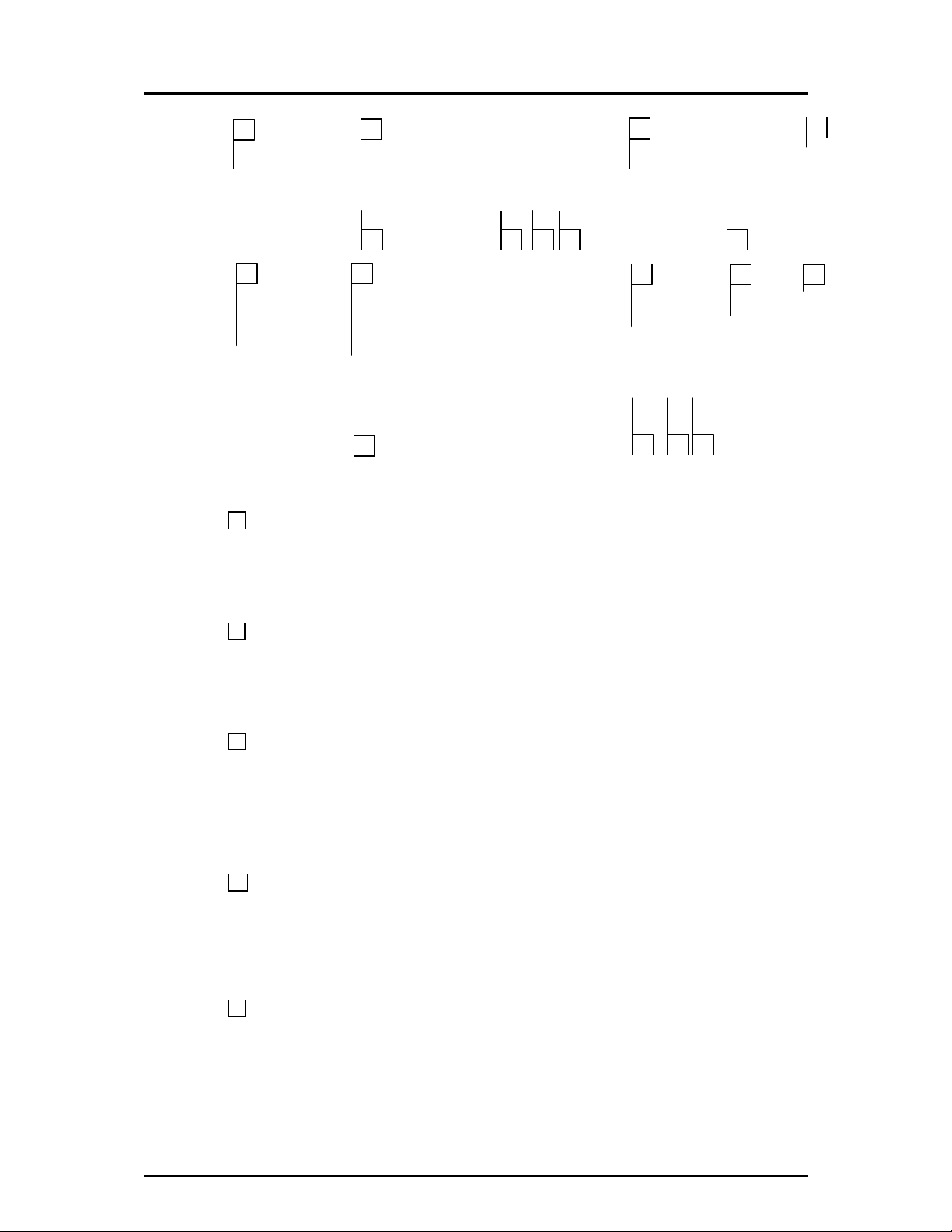
Front Panel
1 Ident Blocks Space is provided for writing on or adhering a label to identify the function of
the associated front panel key. The installer can remove the DR128 front panel plate so that the
label can be fitted behind the window. Do this by removing the four corner hex fixing screws. A
template with instructions is provided in this user guide and in electronic format with the WinDR
software.
2 Function Keys 8 Front panel function keys are provided on the DR66 and 12 on the DR128.
These can be assigned by the installer according to the requirements of the installation. They
would typically be assigned as level trim, channel mute, source select or patch change for day-to-
day operation. If they are not required they can simply be left unassigned. The key function can
change with patch recall if required.
3 Function LEDs Each function key has an associated 3-colour LED indicator. The LED can
be independently assigned as a 3-colour signal meter, or as a green, amber or red status indicator.
For example, it could be an input source meter with signal presence, 0dB and peak indicators for a
key assigned as an input volume control, or a red indicator for a mute key, patch active indicator,
or a colour coded source indicator with colour according to selected source patch. The LED
function does not need to be associated with that of the function key. It can also can change with
patch recall if required.
4 Display A 2x16 character illuminated LCD displays user information during day-to-day
operation, and installer information during setup. When switching the unit on it briefly displays the
boot code version number and then the operating software version number. During normal
operation it displays the current patch name (if loaded), current/last patch numbers as well as time
and day of week. It also momentarily displays channel name and level information when operating
function keys assigned as level controls. The display contrast can be adjusted in Setup mode.
5 SETUP Key Press and hold this key for at least 2 seconds to enter Setup mode. This mode
allows setup of some parameters from the front panel. The earlier V1.xx operating software
versions also allow password protected front panel control of matrix processor parameters and
patch recall. Version 2 restricts this to LCD contrast adjustment and time and day of week
changes while the enhanced parameter set is configured using the PC. The ◄ESC, SET►, ▲UP
and ▼DOWN keys are used to navigate and edit the Setup menus.
7 6 5 2
3
1
9
4
8
1
2
3
4
5 6 7
8 9
DR66 & DR128 Installer User Guide 11
6 ◄ESC Key Press and hold this key while in normal mode to view the operating software
version number. Press ESC while in Setup mode to exit a menu or return to normal operation.
7 ►SET Key This key only functions in Setup mode. Press to advance the menu while setting
up a parameter.
8 UP and DOWN Keys In normal mode these function as level increment/decrement keys
when a function key assigned as a volume up/down selector is pressed, or for scrolling through the
available patches when a function key assigned for patch select is pressed. In Setup mode these
scroll through the available options for the parameter being edited.
9 Rack Ears The rack ears are used to secure the unit into a plinth or standard 19” rack
system. They can be removed for optional desktop operation.
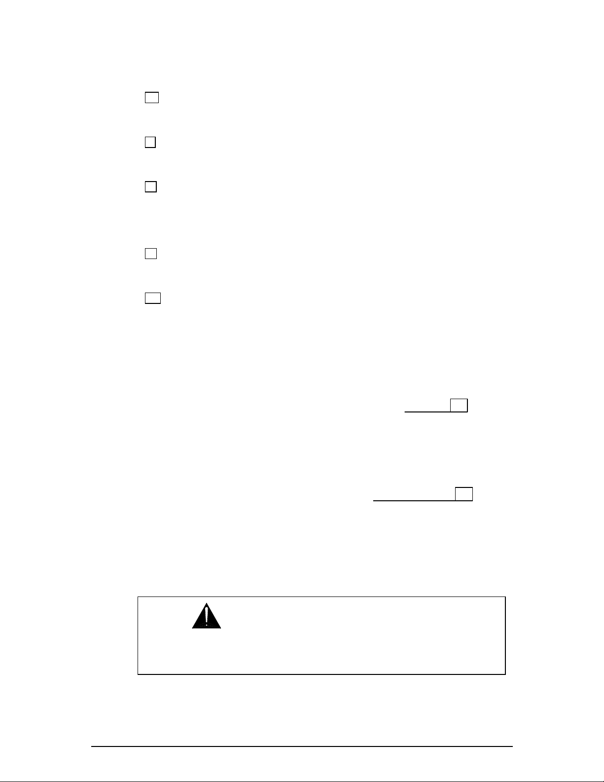
10 Top Cover The installer can remove the top cover of either unit during setup to configure
the hardware for the particular installation. This includes input and output level trim and
microphone phantom power. The optional DSPx and DSPd expander cards can be fitted inside
the unit to extend its processing power. The SysNet option card can be fitted to units running the
earlier Version 1.xx software. Note that Version 2 operating software runs a different SysNet
protocol using the RS232 port and does not require this option. The DR66 system block diagram
is printed on its top cover for convenient installer reference.
DR66
DR128
WARNING: This equipment must be installed and configured by
competent technical personnel only. Ensure the safety instructions printed in
this user guide and on the unit panels are adhered to.
10
10
12 DR66 & DR128 Installer User Guide
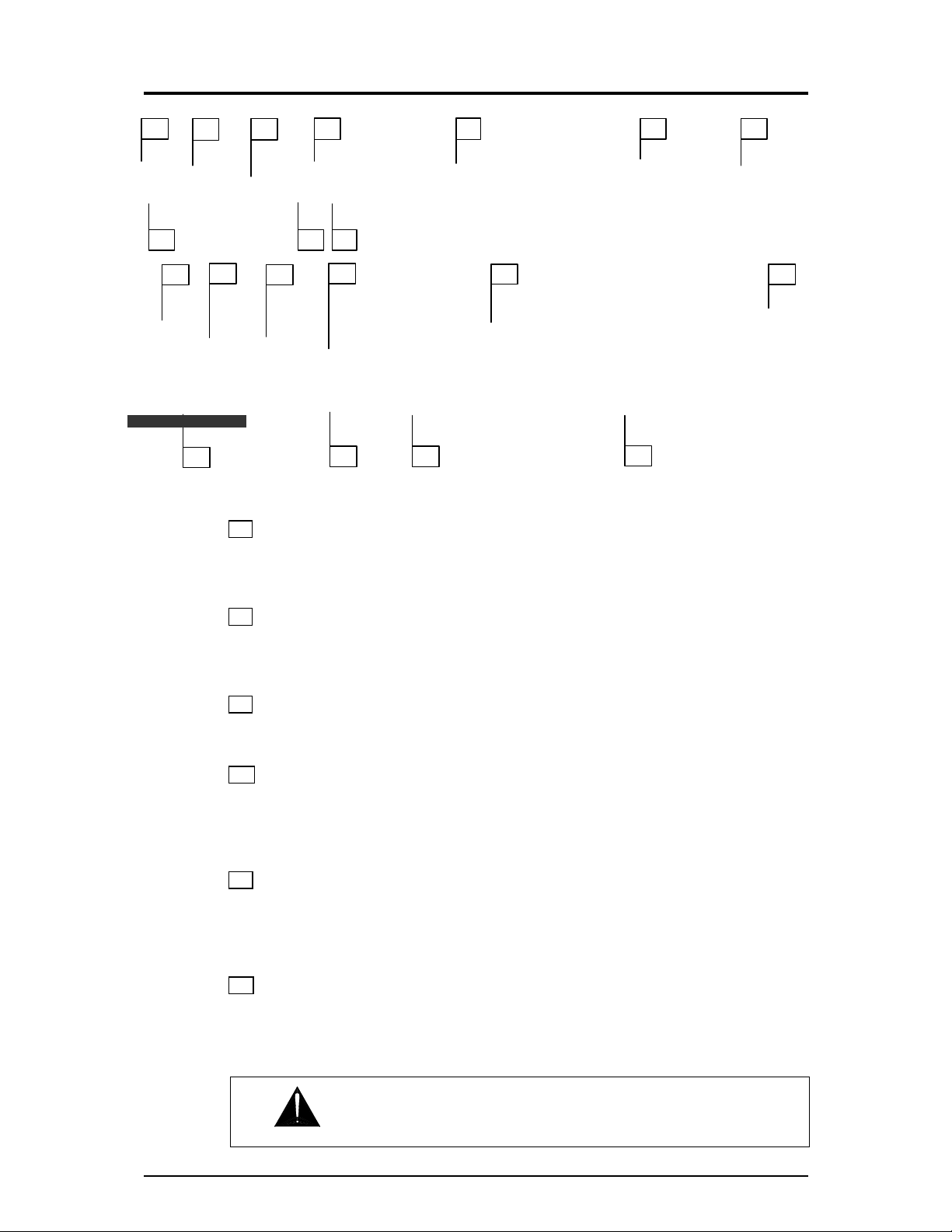
Rear Panel
11 POWER On/Off Switches mains power to the unit. Make sure that WinDR editing software
running on connected PCs is shut down first before switching the unit on or off. WinDR should be
started after the unit has completed its boot up routine to ensure communication is established.
12 MAINS INPUT Fused IEC mains socket with integral voltage selector for the internal power
supply. Note the Mains Voltage Setting and Important Mains Plug Wiring Instructions printed
at the start of this user guide.
13 Serial Number The unit serial number is printed here. Make a note of this to be referred to
in any service communication with Allen & Heath.
14 SysNet Option The optional SysNet card may be fitted here for units running V1.xx
operating software and interfacing to remote equipment using the Allen & Heath SysNet V5
protocol. Note that versions from V2.00 do not require this SysNet card as the revised V6 protocol
is run from the RS232 port. The connector slot is blanked off for future options.
15 RS232 Port 9-pin D-type female socket for plugging in a standard one-to-one wired 9-way
male to 9-way or 25-way female cable to connect to the serial port of a PC. Do not use a Null-
Modem cable. We recommend a cable length no longer than 3 meters for reliable operation. This
port is also used to interface with industry standard controllers using the SysNet V6 protocol.
16 BATTERY Input A 24V DC supply such as a battery may be connected here to provide
backup power in the event of a mains power failure. This switches in automatically when the
mains voltage falls below a certain level. There is no interruption to the operation of the unit. The
DR66 has its battery input on the REMOTE D-type connector. The DR128 has its battery input on
a pair of ¼” terminals.
11 12
13
14
15 18
19 20
16 17
11
16
12
14
15
17
20
19
18
13
WARNING: Adhere to the correct battery terminal polarity.

DR66 & DR128 Installer User Guide 13
17 REMOTE Connections This provides opto-isolated switch closure inputs and opto-isolated
output lines for remote control, for example using wall plates for volume and patch selection. The
DR66 uses a 25-pin D-type female socket providing 12 inputs and 4 outputs. It also includes the
battery input described above. The DR128 uses a 9-pin D-type female socket providing 8 inputs.
It does not provide any outputs. The remote functions are assigned in a similar way to the front
panel keys and indicators.
18 Line Outputs Low impedance, balanced line level audio outputs are provided on male XLR
sockets. The DR66 provides 6 while the DR128 provides 8. These can drive the long cable to the
amplifier racks typical in most installations without signal loss or interference pickup. The
operating level may be adjusted from the low –10dBV standard to the high +4dBu standard using
the internal trimmers or jumpers.
19 Line Inputs 4 mono line input channels are provided for plugging in unbalanced line level
equipment. Dual RCA phono inputs A and B are provided per channel. These can be used to sum
two different sources into one channel, or to sum a stereo source such as CD or MiniDisc player
into mono, typical in background music zoning. Stereo zoning can be achieved by plugging the left
and right sources into different line channels rather than summing them into one for mono. Input
sensitivity can be adjusted for –10dBV to +4dBu using the internal trimmers or jumpers.
20 Mic/Line Inputs Microphones or line level equipment may be plugged into these balanced
XLR inputs. Professional grade discrete pre-amplifiers convert a wide range of source signals to
the operating level required by the unit. The DR66 provides 2 inputs with internal gain trimmers.
The DR128 provides 8 inputs with recessed rear panel gain trimmers. Internal jumper links can be
configured by the installer for attenuator pad and phantom power requirements.
14 DR66 & DR128 Installer User Guide
Installation
This section describes how the unit should be installed into the system furniture, connection to the
mains and battery backup supplies, and cable plugging and routing.
Rack or Desk Mount
The unit is shipped with its rack ears and desk feet fitted. To 19” rack mount, secure the unit into
the rack using 4x M6 bolts with protective cup washers. These are usually supplied with the rack
system. The rack should provide a minimum side to side opening of 445mm. If the space directly
beneath the unit is to be used it may be necessary to remove the attached feet by prising them off.
The rack ears can also be used to secure the unit into a custom plinth or other furniture. To desk
or table mount, remove the rack ears and ensure the feet are fitted.
DR66
Rack Mount
1U high in 19” rack. Width 482mm (19”) Depth 350mm (14”) Height 44mm (1.75”)
Desk or Shelf
Ears removed, feet fitted. Width 440mm (17.3”) Depth 350mm (14”) Height 48mm (1.9”)
DR128
Rack Mount
2U high in 19” rack. Width 482mm (19”) Depth 350mm (14”) Height 88mm (3.5”)
Desk or Shelf
Ears removed, feet fitted. Width 440mm (17.3”) Depth 350mm (14”) Height 92mm (1.9”)
WARNING: Ensure that the front and side air vents are not restricted and
that there is adequate ventilation around the unit. Do not install the unit directly
above or below heat or electromagnetic field generating equipment such as power
supplies or amplifiers. To avoid damage to the internal assemblies do not fit screws
or drill through the sides or underside of the unit. Make provision for removing the
top cover for access to the internal configuration jumpers and trimmers. Allow
adequate space for plugging in the rear connectors and routing the cable harnesses.
A minimum of 75mm (3”) is recommended.
 Loading...