

Page 1
There are plenty of radio goodies about and Chris will guide you to the best buys.
T
he summer Amateur Radio rally and boot sale
season has been in ‘full steam’ and I hope
that, if you’ve been able to visit one, you’ve
managed to pick up a bargain or two. Maybe helped by
recent Buying Secondhand articles in this series.
This time, as promised, I’ll be detailing a couple
of ‘get you going’ high frequency (h.f.) transceivers,
ideally suited for a first ‘all round’ rig and at a price
which hopefully won’t break the bank. The Icom IC-706
and Alinco DX-70 transceivers both offer the ability
of fixed, mobile, and portable operation, and have
broadly similar capabilities.
The first models of each were launched back in
1995, and over the years each transceiver model has
had three different variants, generally an increase in
power at v.h.f., etc. (Please see the description later on
the individual transceivers for more details).
What’s The Cost?
I know one of the first questions readers will ask will
be, “What will one cost me?” This is of course often
hard to say, as in the past when a second-hand ‘buy’
is prominently featured in a magazine such as PW,
this increases the desirability of the rig. However, it
can also often ‘wake up’ people who already have one
that’s lying dormant and unused under the shack desk
or in the house loft and prompt them into selling it!
So, the resultant price – at least for a short while
after such a feature – can either go up or down from
what it was before! But as a guide I believe you
should be able to pick
up first, i.e. early, model
variants of the DX-70 for
under £200 and a first
model variant of the
IC-706 for under £250.
Later models, with more
features and of course
being newer and thus
less-used, will of course
usually attract higher
prices.
I’ve been fortunate
in using various models
of both the DX-70 and
the IC-706 myself in the
past, each of them at
home and out and about
in my car. This as well
as being able to fully
and stringently test them at the time for technical
performance in my measurement lab. So, I’ve no
hesitation in recommending either to readers as a
second-hand radio, providing of course you follow my
advice regarding each one!
I know the DX-70 has been, and probably still is,
a ‘favourite’ of the PW Editor Rob Mannion G3XFD.
I must admit to having a personal preference for the
IC-706GMkII (albeit available at a higher price), but that
again is personal preference and each radio would be
ideal as starter or all-rounder transceiver.
Having said that, the DX-70 has stood the test of
time and after 15 years from its launch, the latest
model in the DX-70 series, unlike other radios that
have faded in the past, is still here on the market and
selling well!
Now for couple of points to watch out for when
you’re buying second-hand. The first is the inclusion,
or not, of CTCSS (sub-tone) in the IC-706, or whether
you need to add an optional module for this. It will be
important if you’re interested in 50, 144 and 430MHz
repeater operation rather than single sideband (s.s.b./
c.w. (Morse).
Secondly, you should check whether either rig
has extended 7MHz (40m) band transceive coverage.
Additionally, you need to check for
5MHz band
c
over
age transmit if you’re licensed for this or hope
to be in the future. If not then don’t worry too much,
because for each transceiver model featured I’ve given
details on how to add this to a second-hand radio.
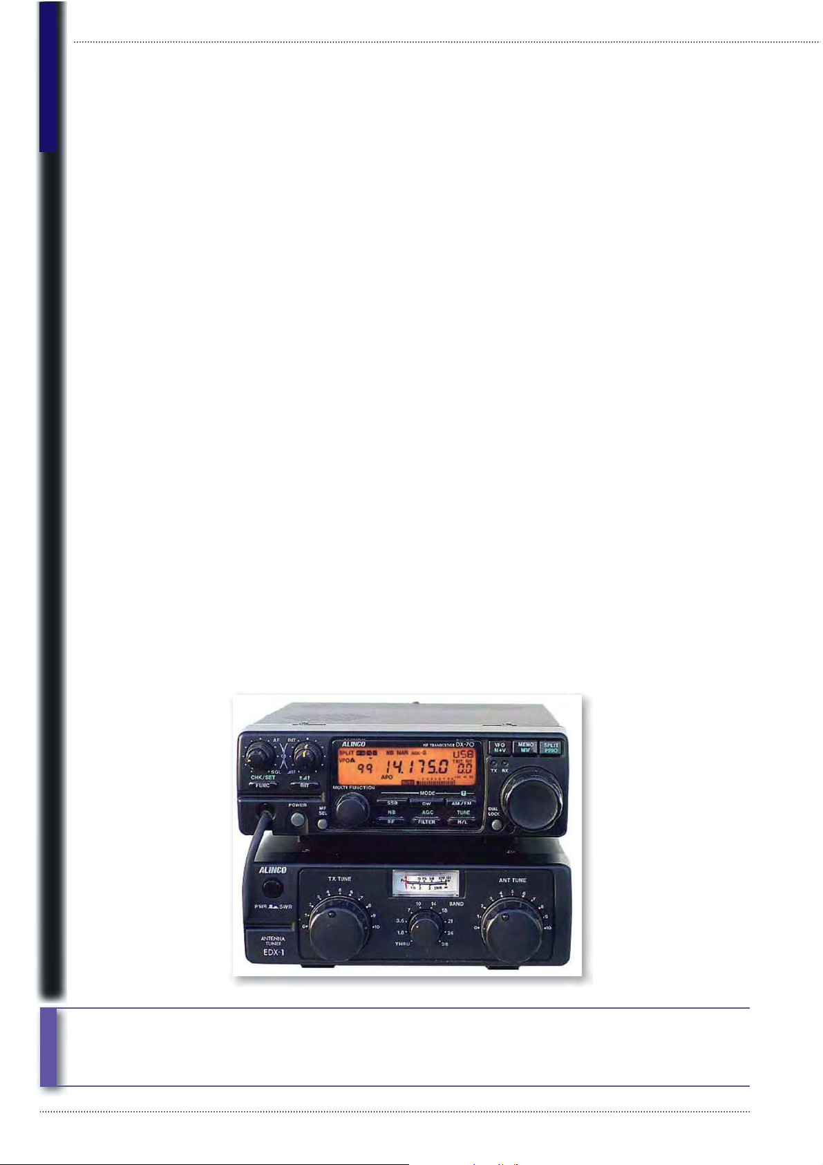
The Alinco DX-70
The first DX-70, Fig. 1, first
appeared in early 1995,
and offers h.f. and 50MHz
transceiver coverage on
amplitude modulation
(a.m.), c.w., narrow band
frequency modulation
(n.b.f.m.) and s.s.b. The rig
has 100W output on h.f.
(switchable to 10W for low
lower operation) plus 10W
on 50MHz, switchable
to 1W low power. A little
later came the DX-70T,
which was virtually the
same as the DX-70 but
with narrow filters fitted
as standard.
Fig. 1: The original Alinco DX-70 with its matching antenna ‘tuning’ unit.
Buying Second-hand
Feature
Practical Wireless, November 2010
42
Chris Lorek G4HCL takes a look at several h.f. transceivers which you can hopefully
pick up at a bargain price.
Page 2
Finally, in 1999 the
DX-70TH, Fig. 2, was
launched, and this model
is in fact still available and
on current sale – it’s similar
to the DX-70T but the ‘H’
signifies it has a higher
power of 100W on 6m. The
operation and appearance of
each is identical apart from
the model number on the
front and rear panels.
Each model has a transmit
frequency range within the
normal Amateur bands, and
a receive coverage of 150kHz
– 30MHz and 50 – 54MHz. A
built-in continuous tone coded
squelch system (CTCSS)
tone encoder is included –
invaluable for 28 and 50MHz
n.b.f.m. (usually referred to as
f.m.) repeater use.
Narrow (1kHz) and wide
(2.4kHz) intermediate
frequency (i.f.) filters are
available for c.w./s.s.b. and
‘narrow a.m.’ receive. These
being switchable from the front panel, together with a
further wider filter for normal a.m. and f.m. use. A 500Hz
filter is automatically switched in when c.w. mode is
selec
ted.
An IF s
hift control helps in fighting adjacent frequency
interference on a crowded band, and switchable 10dB and
20dB receive attenuators help guard against overload, a
10dB preamplifier also being fitted. This is for use when
needed on a ‘quiet’ band or for example whilst mobile
with a small antenna. Two antenna sockets are fitted to
the rear panel, one for h.f. and the other for 50MHz. The
set’s dimensions are 178 W x 58 H x 228mm D.
The front panel can be detached and an optional
cable used to link this to the main transceiver ‘body’,
which you can then mount elsewhere, maybe next to
the feed-point of your mobile h.f. antenna. However, the
microphone and speaker connections stay at the main
transceiver end, so although you’ll need extension leads
here, but you can detach the front panel without any
further connections and take it with you when you leave
the car.
For on-air use, there’s an internal speech processor
and for c.w. operators,
full and semi-break in. When I
u
sed th
e set on-air I found the smooth VFO knob control
easy to use although I quickly learned how to use the set
by touch alone for mobile use. I also quickly learned that
I – invariably – had to use the Dial Lock button to keep
me on frequency during a contact on the move as I found
that I could easy accidentally knock the
VFO control
kn
ob.
F
or normal mobile use, the set’s 100 memory
channels were useful. These, combined with a single
button-push ‘memory to VFO’ operation enables this to
act as a band switch for Amateur and broadcast bands.
At home I must confess,
I found the set’s receiver
often suf fered on busy
bands if I connected my fullsize dipole on the l.f. bands,
or my tower-mounted
3-element quad-bander
Yagi beam on the higher
bands and pointed at a busy
Europe.
But then, the DX-70TH
is a small set, and the
attenuator function was
useful here. However, in
fairness – many users
of a transceiver such as
this may not be using
‘monster’ antennas, using
more compact types. My
conclusions after I’d used
the rig those years ago were
that Alinco had surprised the
Amateur Radio world with
a radical departure from
their previous v.h.f./u.h.f.
f.m. only offerings. But that
they’d managed to do a very
good job, as I found no real
limitations with the set considering it’s size and features.
Things To Watch For
Now, let’s look at the things to watch for on the DX-70
series of rigs. As well as the usual ‘bewares’ which I gave
details of in the first column in this Buying Second-hand
series, such as buying and ownership warnings, look out
for severe scratching to the case if the previous owner or
owners have repeatedly taken it in and out of a car. If just
the front panel has been removed this won’t usually be
an issue, but here check the connections aren’t corroded
nor the front panel display fascia scratched.
See my recent article on the TM-G707E and IC-207
in the July 2010 issue of PW for information on how
to remove any scratches if your seller hasn’t been too
careful in the past.
Electrical problems with the PIN diodes, which are
used to switch the antenna path between the transmitter
power amplifier and receiver front end circuits, have
to my knowledge been reported causes of failure.
So it would be a good idea to check a second hand
transceiver on-air for r.f. power output (e.g. with an
in-line power meter) and receiver sensitivity – here you
should hear an increase in background noise on the
lower h.f. bands when you connect an antenna.
Extended Transmit Frequency
For the extended 7MHz (40m) band and for the 5MHz
band – if you’d like to use these on transmit, check your
seller has had extended transmit range enabled. But if
not, here’s how to go about it.
Remove the control head, remove the four screws
from the back of this, then remove the rear panel of
the control head – it’s a ‘snap fit’ so you may need to
Practical Wireless, November 2010
43
Fig. 2: The current version of the DX-70, the ‘TH’ version has been improved and
adds more output power of 100W at 50MHz.
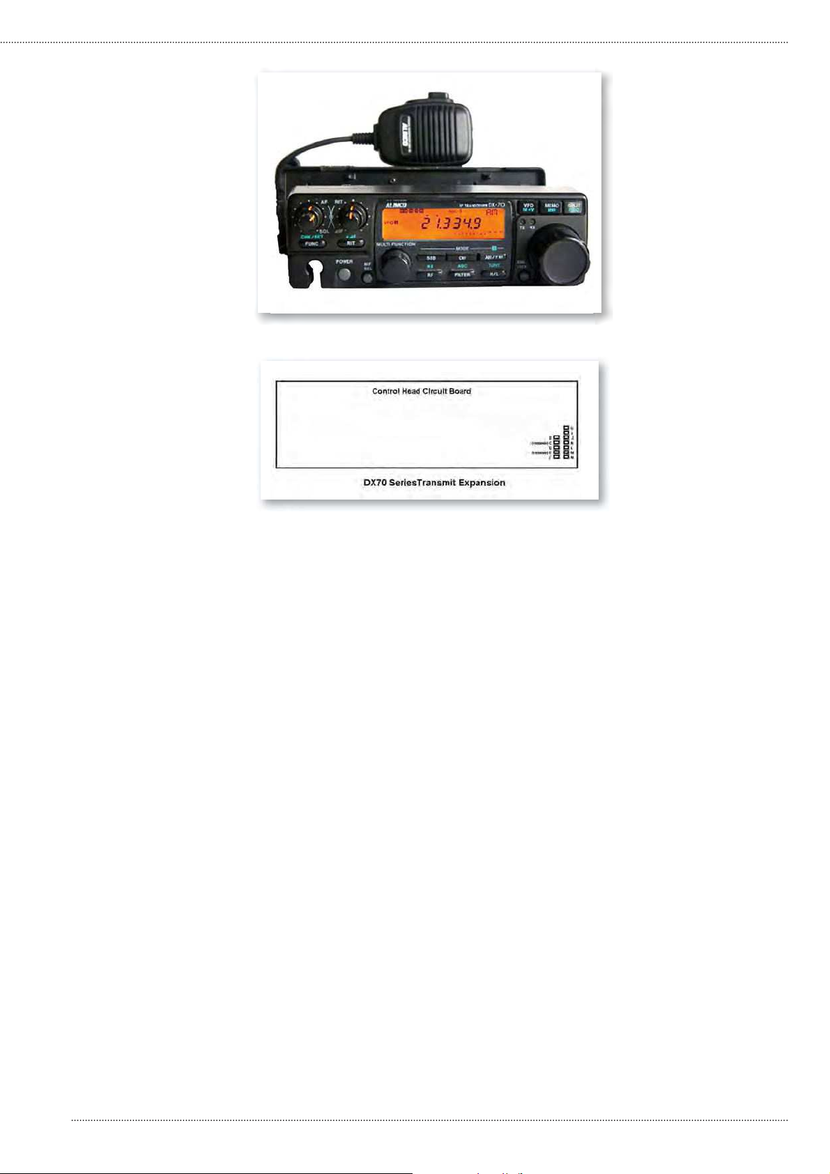
Fig. 3: See the text for expanding the transmit receive capabilities of the Alinco
DX-70 series. There is no pad labelled ‘A’ on the left-hand column.
Page 3

Buying Second-hand
prise it of f. Looking at the
printed circuit board, with
the display fascia away from
you and the tuning knob
on the left hand side, you’ll
see on the bottom right
hand side of the board two
columns of solder pads for
surface-mount resistors, five
on the left hand row and
seven on the right hand row,
Fig. 3.
Note that not all resistors
may be fitted and that
they’re not labelled. Above
each row is a distinct solder
pad. To extend the transmit
range, refer to Fig. 3 and
remove diodes labelled
C and E on the diagram
(second and fourth down
in the left hand column). Following this, reassemble the
control head and per form a reset of the transceiver by
keeping the F button pressed at the same time as you
switch the radio on. Your memory channels, etc., will
be re-set but the radio will now operate with extended
transmit range.
The Icom IC-706 & IC706G
Now let’s turn to the IC-706 which, was launched in the
latter half of 1995 and was an obvious competitor to the
Alinco DX-70. At the time of its launch it was the most
talked-about radio for many years and when the first batch
arrived in the UK they were very quickly sold. In fact, I know
there were several hundred UK Amateurs on the ‘waiting
list’, with the USA ‘waiting list’ of around 4000 Amateurs.
As with the Alinco DX-70 it also offers an h.f. and 50MHz
multi-mode transceiver, with a detachable front panel, in a
similar sized case. It also came with optional narrow filters
and the same frequency range – but with added 144MHz
transceiver coverage and wide-band f.m. reception.
The transceiver measures 167(W) x 58 (H) x 200mm
(D), and like the DX-70 it has a removable front panel to
allow you to take this with you when you leave the vehicle.
An optional remote
cable kit is again also
available to allow you to
remotely mount the radio
body away from the car
dashboard, Fig 4.
A very comprehensive
range of operating
features are built-in (too
many to mention in detail
here) and you’ll need a
good read of the manual
to learn how to operate
them all! Note however,
that CTCSS isn’t fitted as
standard in the IC-706 and
IC-706G – so you’ll need
an optional internal add-on
board for this.
The transceiver offered
up to 100W output on
both h.f. and 50MHz,
plus the added ‘bonus’ of
the 144MHz transceiver
coverage with 10W transmit
output – as well as a general
coverage receiver tuning
from 30kHz to 200MHz.
As such it had the edge
over the DX-70 in terms of
features but came along at a
higher price, which secondhand models hold, typically
£50-90 more than the DX-70
at the time I write this article.
Just a few years later,
the IC-706MkII, Fig. 5,
came along, this had better
technical performance
than the original IC-706 along with a doubling of the
144MHz transmit output power of 20W. Still later on,
the IC-706MkIIG came on sale, which increased the 2m
transmit power output further to 50W (adjustable down to
5W) and, significantly, added 430MHz (70cm) multi-mode
transceive coverage with a transmitter power output of 20W
maximum, adjustable down to 2W for low power operation.
This later model was, I’m sure, intended to appeal to
users who’d like a combined h.f. mobile rig, together with a
2m/70cm dual band rig for mobile repeater operation and
the advantage of a multi-mode all-band rig for hilltop DX
operation.
When I used the set, coupled to my h.f. antenna system
at home (a combination of wires, dipoles and beams), it
operated reasonably well, although I usually needed to have
the r.f. pre-amplifier switched in on ‘quiet’ bands such as the
upper h.f. bands and v.h.f. While on 3.5MHz (80m) and 40m,
at night, the set suffered a little from strong signals and I
typically needed to have the attenuator switched in.
When operating mobile, I tended to use the memory
channels almost continuously, every channel acted virtually
as a ‘separate v.f.o.’ – I could simply tune away from each as
I wanted with a turn of the tuning knob. This knob usefully
had a small tension
adjustment lever, either
stiff for mobile use, or
free-wheeling for shack
use – which I appreciated.
The IC-706MkII
The IC-706MkIIG
was provided with a
highe
r power – 50W
on 144MHz, together
with 430MHz coverage
and Icom included the
CTCSS sub-tone encode
and decode as standard.
This could previously
be added as an optional
plug-in unit, but with
Practical Wireless, November 2010
44
Fig. 5: The IC-706MkIIG offered operation on the major Amateur bands from h.f. to u.h.f.
Fig. 4: As with the Alinco DX-70, the IC-706 series can have a remote location for
the control head, making it easier to remove the unit, when not in use.
Page 4

this version it was built in as part of the
main p.c.b. circuitry.
The ‘G Mark II also has a
useful standing wave ratio (s.w.r.)
measurement facility on h.f. and
50MHz.The facility is not just on
the tuned (working) frequency but
either side of this, with a simple SWR
bargraph display, which appears along
the bottom section of the liquid crystal
display(l.c.d.) panel.
Mobile whips can have a rather
narrow bandwidth on h.f., and you can
only shift frequency so far before the
s.w.r. becomes too high, so this could
be rather useful for mobile operators.
On air I found the performance on
receive had the edge over the original IC-706, this
being reflected in the lab measurements I’d made. The
IC-706MkII would also have a similar receive performance
improvement.
Things To Watch For
With the IC-706 and IC-706MkIIG an important thing
to bear in mind – if you intend to operate the set on
144MHz and, with the IC-706MkIIG, on 430MHz, is to
make sure there’s a CTCSS option board internally fitted
to the set you’re intending to buy. As these transceivers
aren’t current models you may well have dif ficulty
finding a CTCSS board. So check first if one is available
if this is important to you before agreeing to buy a set
without CTCSS. The IC-706MkIIG has CTCSS fitted as
standard.
Again if you want to operate on the whole of the
7MHz band, check it has extended transmit coverage.
But if it hasn’t, I’ve detailed the modification for each
variant of the set below.
The microphone connector on each model plugs into
the lower front of the set, with the microphone lead
going ver tically downwards. This could have imposed
strain on the lead where it enters the plastic plug,
causing intermit tent operation, especially if the rig was
used as a mobile by the previous owner(s).
If you can inspect and test the radio first, wiggle
the lead about while you’re transmitting, and check for
any breaks in your transmitted audio and intermittent
transmission. It’s not too serious as you can slightly
shor ten the lead a little, but you’ll
need a new plug and a special plug
‘crimping tool’ to fit this.
Extended Transmit
Frequency
Extending the transmit frequency
range for the IC-706 series isn’t
difficult. For operation on the
extended 40m (7MHz) band you’ll
need to ensure your radio is enabled
for this, also for 5MHz, here are the
details for each variant;.
The IC-706: On the main printed
circuit board (p.c.b.) by the filter
option location, you’ll see a row of
five surface mounted dual diodes, Fig.
6, next to a jumper wire. Using a small (but hot) soldering
iron, lift up the lead(s) on one end of D59 to disconnect it
(or if you wish) also then heat up the lead(s) on other side
and remove it completely.
The IC-706MkII: On the main p.c.b., you’ll see an
oblong metal can, and near to this are a few rows of
surface mount diodes. Take a look at the accompanying
diagram, Fig. 7, and, using a small (but hot) soldering
iron, remove D116 and D118 by applying heat to one of
the legs and lifting the diode away from the board.
The IC-706MkIIG; On the main p.c.b., under the
speaker near to the crystal, you’ll see two rows of solder
pads for surface mount components, Fig. 8. On position
10 along this row from the left you’ll see a diode, D2030,
soldered in. Simply remove this diode using a small (but
hot) soldering iron on the leads. After you re-connect
your d.c. supply the radio will be automatically reset and
the transmit range expanded on h.f. and v.h.f.
Next Time
That’s it for this month and I shall be back soon with a
further Buying Second-hand column. If you’d like any
particular types of radios covered in this series then
please do get in touch. I’ve already a nice pile of ideas
and information in the pipeline – but I’d welcome being
guided further by readers’ interests.
I can be contacted by E-mail to g4hcl@rsgb.org.uk or
by post to PO Box 400, Eastleigh, Hampshire SO53 4ZF,
UK. ‘Bye for now, see you next time!
O
Practical Wireless, November 2010
45
Fig. 6: Expanding the capabilities of the original IC-706 is as
suggested in the text.
Fig. 7: To expand the capabilities of the MkII version of the IC-706,
see text for more detail.
Fig. 8: And the IC-706MkIIG has another version
of expanding its capabilities. See text for the
differences of the various models of the IC-706.
 Loading...