

Page 1

ALINCO, INC.
Y
odoyabashi Dai-bldg 13F
4-4-9 Koraibashi, Chuo-ku, Osaka 541-0043 Japan
Phone: +81-6-7636-2362 Fax: +81-6-6208-3802
http://www.alinco.com
E-mail:export@alinco.co.jp
A1.140220
VHF/UHF FM
Transceiver DR638
All EU and EFTA member states. Operator
license is required.
FCC ID:PH3-DR638
IC:3070C-DR638
Copyright Alinco, lnc. PS0665A/FNEG-NI
Printed in China
Page 2
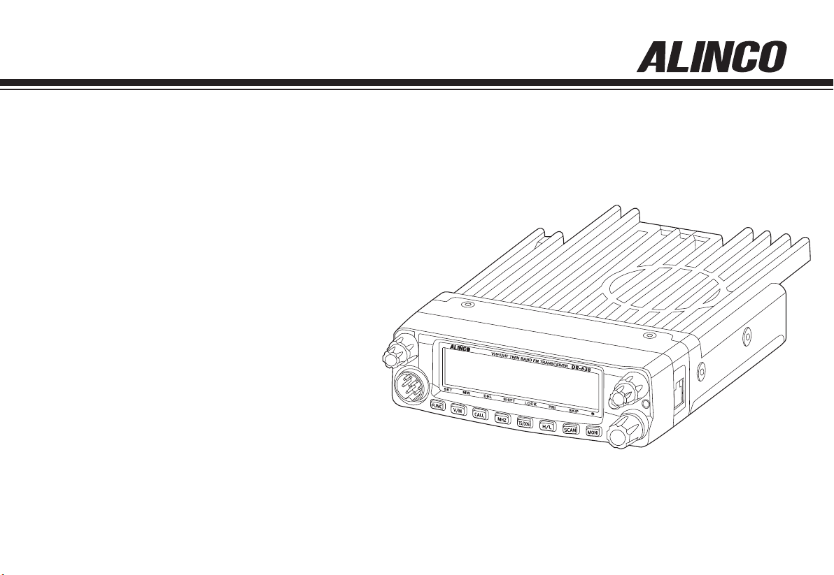
VHF/UHF FM T
ransceiver
DR-638
Instruction Manual
Thank you for purchasing your new Alinco transceiver.
Please read this manual carefully before using the
product to ensure full performance, and keep this
manual for future reference as it contains information
on after-sales services. In case addendum or errata
sheets are included with this product, please read
those materials and keep them together with this
instruction manual for future reference.
NOTE: DR-638 may be delivered to you after dealer-programming.
In such cases, please ask your dealer about the available
features in your unit and how to operate this unit.
Page 3
Introduction
Thank you very much for purchasing this excellent Alinco transceiver.
Our products are ranked among the finest in the world. This radio has
been manufactured with state of the art technology and it has been tested
carefully at our factory. It is designed to operate to your satisfaction for
many years under normal use.
Please read this manual completely from the first page to the
last, to learn all the functions the product offers. It is important to
note that some of the operations may be explained in relation to
information in previous chapters. By reading just one part of the
manual, you may risk not understanding the complete explanation
of the function.
Conformity Symbols
Tested to comply MIL-STD-810G
-Shock: Method 514.6/I,IV -Vibration: Method 516.6/I
Conformity Information
Before transmitting
There are many radio stations operating in proximity to the frequency
ranges this product covers. Be careful not to cause interference when
transmitting around such radio stations.
■
Lightning
Please note that no car provides adequate protection of its passengers
or drivers against lightning. Therefore, Alinco will not take responsibility
for any danger associated with using its radios or inside the car during
lightning.
■
For North American users
Due to strict rules, this product is blocked for operations before sales
and only dealers can program the radio before delivery to consumers.
Manufacturer is n ot aware of details of such dealer-pr og ra mm in g
therefore please kindly contact your dealer rst in case technical-service
may be necessary.
In case the unit you have purchased is marked with a CE symbol,a copy
of relative conformity certicate or docu-ment can be reviewed at http://
www.alinco.com/usa.html.Please see the back-cover for more details.
Copyright 2012 All rights reserved. NO part of this document may be
reproduced, copied, translated or transcribed in any form or by any
means without the prior writhout the prior written permission of Alinco.
Inc,Osaka, Japan, English Edition Printed in China.
Comformity information / Amateur radio version
Manufacturer:
ALINCO, Inc. Electronics Division
Yodoyabashi Dai-bldg. 13F
4-4-9 Koraibashi, Chuo-ku,
Osaka 541-0043 Japan
Page 4

FCC NOTICE / Compliance Information Statement
This equipment has been tested and found to comply with the limits for a
Class B digital device, pursuant to part 15 of the FCC Rules.
These limits are designed to provide reasonable protection against
harmful interference in a residential installation.
This equipment generates, uses, and can radiate radio frequency energy
and, if not installed and used in accordance with the instruction manual,
may cause harmful interference to radio communications. However, there
is no guarantee that interference will not occur in a particular installation.
If this equipment does cause harmful interference to radio or television
reception, which can be determined by turning the equipment off and on,
the user is encouraged to try to correct the interference by one or more
of the following measures:
• Reorient or relocate the receiving antenna.
• Increase the separation between the equipment and receiver.
• Connect the equipment into an outlet on a circuit different from that to
which the receiver is connected.
• Consult the dealer or an experienced radio/TV technician for help.
Tested to Comply
With FCC Standards
FOR HOME OR OFFICE USE
Information in this document is subject to change without notice or
obligation. All brand names and trademarks are the property of their
respective owners. Alinco cannot be liable for pictorial or typographical
inaccuracies. Some parts, options and/or accessories are unavailable
in certain areas. Changes or modifications not expressly approved by
the party responsible for compliance could void the user's authority to
operate the equipment.
This device complies with Part 15 of the FCC Rules. Operation is subject
to the following two conditions: (1) This device may not cause harmful
interference, and (2)this device must accept any interference received,
including interference that may cause undesired operation.
customers in Canada :
MODEL: 3070C-DR638
Le pré sen t a p par eil est con for me aux CNR d'I ndus tri e C a nad a
applicables aux appareils radio exempts de licence. L'exploitation est
autorisée aux deux conditions suivantes :
(1) l'appareil ne doit pas produire de brouillage, et.
(2) l'utilisateur de l'appareil doit accepter tout brouillage radioélectrique
subi, même si le brouillage est susceptible d'en compromettre le
fonctionnement.
CE Conformity Information
This device is in compliance with the essential requirements of R&TTE
Directive 1999/5/EC.
A copy of the certicate by the notied body can be reviewed at http://
www.alinco.com/usa.html.
This device is authorized for use in all EU and EFTA member states.
An operator's license is required for this device.
Page 5

Trash bin icon / Rohs Icon
IMPORTANT: This manual is common to amateur and commercial
users.
Not all features are available to commercial users. Commercial-use units
are programmed by the dealer before sales therefore features may be
prohibited for manual access by the users.
Commercial-users should contact the dealer for any technical inquiry
because the distributor and manufacturer are not aware of the details of
dealer-programming.
F e a t u r e s li k e sc l a m b l i n g is n o t al l o w e d fo r am a t e u r ra d i o
communications.
Page 6

SAFETY TRAINING
INFORMATION
Land-mobile version only
WARNING:
This radio generates RF electromagnetic energy during transmission.
This radio is designed for and classified as “Occupational Use Only”,
meaning it must be used only during the course of employment by
indiv iduals aw are of th e hazards, and the w ays to mi nimize su ch
hazards.This radio is NOT intended for use by the “GeneralPopulation”
in an uncontrolled environment.
• Fo r c omp lia nce wit h F CC and Ind ust ry Can ada RF Exp osu re
Requirements, the transmitter antenna installation shall comply with
the following two conditions:
1.The transmitter antenna gain shall not exceed 0 dBi.
2.The antenna is required to be located outside of a vehicle and kept
at a distance of 63 centimeters or more between the transmitting
antenna of this device and any persons during operation.For small
vehicle as worst case, the antenna shall be located on the roof top
at any place on the centre line along the vehicle in order to achieve
63 centimeters separation distance. In order to ensure this distance
is met, the installation of the antenna must be mounted at least 63
centimeters away from the nearest edge of the vehicle in order to
protect against exposure to bystanders.
CAUTION:
To ensure that your exposure to RF electromagnetic energy is within
the FCC allowable limits for occupational use, always adhere to the
following guidelines:
DO NOT operate the radio without a proper antenna attached, as this
•
may damage the radio and may also cause you to exceed FCC RF
exposure limits. A proper antenna is the antenna supplied with this
radio by the manufacturer or an antenna specically authorized by the
manufacturer for use with this radio.
DO NOT transmit for more than 50% during the time of employment
•
(50% duty cycle or less). Transmitting excessive amount of time can
cause RF exposure compliance requirements to be exceeded. Please
carefully read this instruction manual to learn how to transmit and stop
transmitting before starting to use it.
Electromagnetic Interference/Compatibility
Du ring tra nsm iss ion s, your rad io gen erate s R F e nergy that can
possibly cause interference with other devices or systems. To avoid
such interference, turn off the radio in areas where signs are posted to
do so. DO NOT operate the transmitter in areas that are sensitive to
electromagnetic radiation such as hospitals, aircraft, and blasting sites.
Occupational/Controlled Use
This product is used in situations that users are exposed to RF as
consequence of their employment provided those users are fully aware
of the potential RF hazards and can exercise control over their exposure.
This transceiver is NOT ATEX approved and NOT intended for the use
•
in hazardous explosive atmospheres.
PC PROGRAMMING
NOTE: The utility software may be available to distributors/dealers only.
USB programming cable is required. The manufacturer will not release
the software to unauthorized party so please contact your dealer for
details.
Page 7

FCC INFORMATION / LAND-MOBILE VERSION ONLY
FOR CLASS B UNINTENTIONAL RADIATORS:
This equipment has been tested and found to comply with the limits for a
Class B digital device, pursuant to part 15 of the FCC Rules.
These limits are designed to provide reasonable protection against
harmful interference in a residential installation.
This equipment generates, uses and can radiate radio frequency energy
and, if not installed and used in accordance with the instructions, may
cause harmful interference to radio communications. However, there is
no guarantee that interference will not occur in a particular installation.
If this equipment does cause harmful interference to radio or television
reception, which can be determined by turning the equipment off and on,
the user is encouraged to try to correct the interference by one or more
of the following measures:
Reorient or relocate the receiving antenna. ●
Increase the separation between the equipment and receiver. ●
Connect the equipment into an outlet on a circuit different from that to ●
which the receiver is connected.
Consult the dealer or an experienced radio/TV technician for help. ●
FOR CUSTOMERS IN CANADA :
Le présent appareil est conforme aux CNR d'Industrie Canada applicables
aux appareils radio exempts de licence.
L'EXPLOITATION EST AUTORISÉE AUX DEUX CONDITIONS SUIVANTES :
(1) l'appareil ne doit pas produire de brouillage, et
(2) l'utilisateur de l'appareil doit accepter tout brouillage radioélectrique
subi, même si le brouillage est susceptible d'en compromettre le
fonctionnement.
Page 8
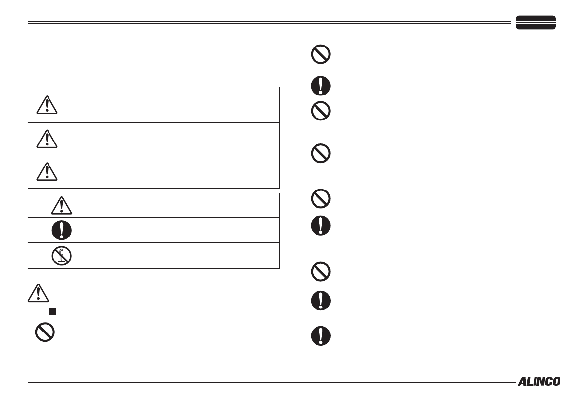
To prevent any hazard during operation of Alinco’s radio product, in this
manual and on the product you may nd symbols shown below. Please
read and understand the meanings of these symbols before starting to
use the product.
Danger
Alert
Caution
This s ymbol i s inten de d to alert the user t o an
immediate danger that may cause loss of life and
property if the user disregards the warning.
This symbol is intended to alert the user to a possible
hazard that may cause loss of life and property if the
user disregards the warning.
This symbol is intended to alert the user a possible
hazard that may cause loss of property or injure the
user if the warning is disregarded.
Alert symbol. An explanation is given.
Warning symbol. An explanation is given.
Instruction symbol. An explanation is given.
WARNING
Do not use this product in close proximity to other electronics
devices, especially medical ones. It may cause interference
to those devices.
Keep the radio out of the reach of children.
In case a liquid leaks from the product, do not touch it. It may
damage your skin.
Rinse with plenty of cold water if the liquid contacted your
skin.
Never operate this product in facilities where radio products
are prohibited for use such as aboard aircraft, in airports, in
ports, within or near the operating area of business wireless
stations or their relay stations.
Use of this product may be prohibited or illegal outside of
your country. Be informed in advance when you travel.
The m an ufacturer decli ne s any responsibilit ie s against
loss of life and/or property due to a failure of this product
when used to perform important tasks like life-guarding,
surveillance, and rescue.
Do not use multiple radios in very close proximity. It may
cause interference and/or damage to the product(s).
ALERT
Environment and condition of use:
Do n ot drive whi le handlin g the r adio for y our saf ety. It
is recomm en de d that y ou check local traffi c regulations
regarding the use of radio equipment while driving.
Some countries prohibit the operation of transceiver while
driving.
The manufacturer declines any responsibilities against loss
of life and property due to a failure of this product when used
with or as a part of a device made by third parties.
Use of third party accessory may result in damage to this
product. It will void our warranty for repair.
Page 9
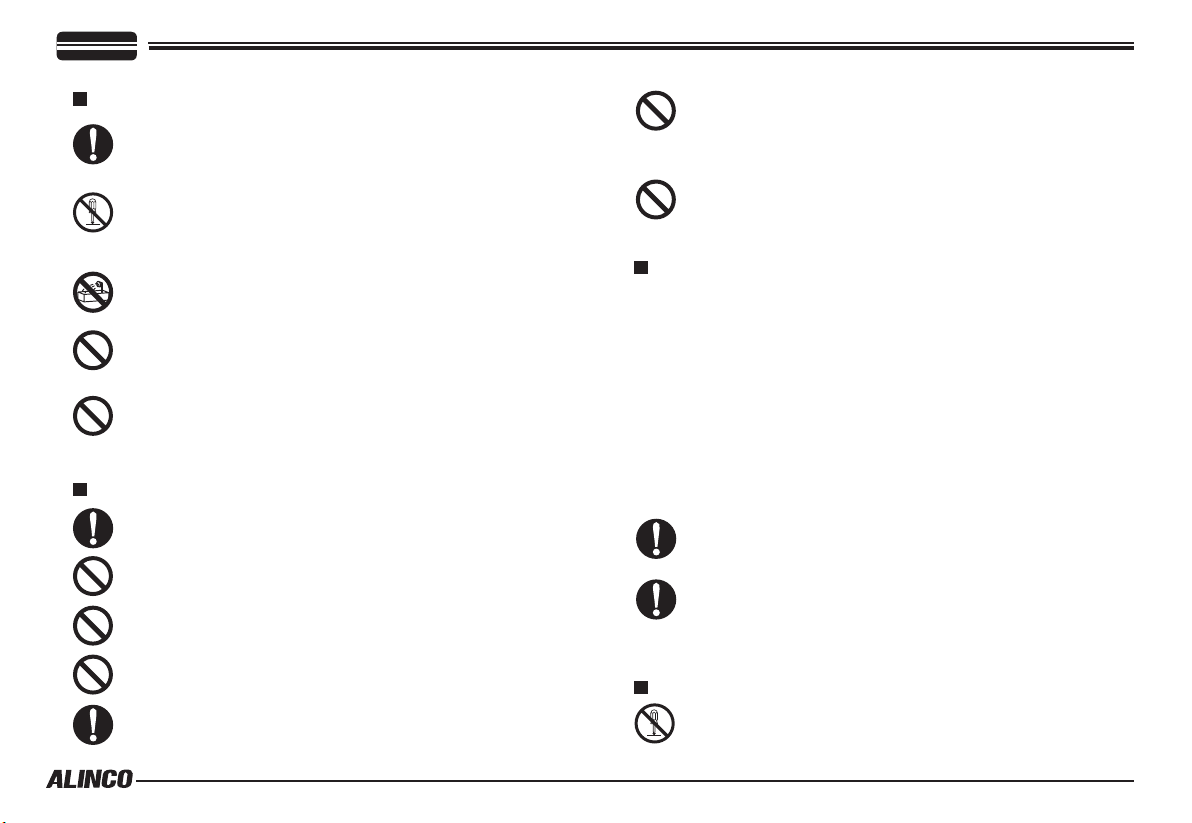
WARNING
Handling this product:
Be sure to reduce the audio output level to minimum before
using an earphone or a headset. Excessive audio may damage
hearing.
Do not open the unit without permission or instruction from the
manufacturer.
Unauthorized modication or repair may result in electric shock,
re and/or malfunction.
Do not operate this product in a wet place such as shower
room. It may result in electric shock, re and/or malfunction.
Do not place conductive materials, such as water or metal in
close proximity to the product. A short-circuit to the product
may result in electric shock, re and/or malfunction.
Do not touch the heatsink (on/around the unit mostly found on
mobile-base units) as it may become very hot during/after the
operation that may risk burn your skin.
About power-supply:
Use only appropriate, reliable and certified power supply of
correct voltage and capacity.
Do not connect cables in reverse polarity. It may result in
electric shock, re and/or malfunction.
Do not plug multiple devices including the power-supply into a
single wall outlet. It may result in overheating and/or re.
Do not handle a power-supply with a wet hand. It may result in
electric shock.
Securely plug the power-supply to the wall outlet. Insecure
installation may result in short-circuit, electronic shock and/or re.
Do not plu g the power-suppl y into the wall o ut let if the
contacts are dirty and/or dusty.
Shortcircuiting and/or overheating may result in re, electric
shock and/or damage to the product.
Do not modify or remove fuse-assembly from the DC-cable.
It may result in f ire, electric shock and/or damage to the
product.
In case of emergency:
In case of the following situation(s), please turn off the product, switch
off the source of power, then remove or unplug the power-cord. Please
contact your local dealer of this product for service and assistance.
Do not use the product until the trouble is resolved. Do not try to
troubleshoot the problem by yourself.
• When a strange sound, smoke and or strange odor comes out of the
product.
• When the product is dropped or the case is broken or cracked.
• When a liquid penetrated inside.
• When a power-cord ( including DC-cables, AC-cables and adapters)
is damaged.
For your safety, turn off then remove all related AC-lines to
the product and its accessories including the antenna if a
thunderstorm is likely.
Turn off the unit, remove the mobile antenna from its base
and keep it in the vehicle if a thunderstorm is likely.
Please read cautions regarding the lightning-protection on
page 9 also.
Maintenance
Do not open the unit and its accessories. Please consult with
your local dealer of this product for service and assistance.
Page 10
WARNING
CAUTION
Environment and condition of use:
Do not use the product in proximity to a TV or a radio. It may
cause interference or receive interference.
Do not install in a humid, dusty or insufficiently ventilated
place. It may result in electric shock, re and/or malfunction.
Do not install in an unstable or vibrating position. It may result
in electric shock, re and/or malfunction when/if the product
falls to the ground.
Do not install the product in proximity to a source of heat and
humidity such as a heater or a stove. Avoid placing the unit in
direct sunlight.
Do not modify, dismantle, incinerate, or immerse the batteries
that may be used in accessories you use with this product.
Please check your local regulations for details on recycling
option or disposal of the batteries in your area.
About transceiver
Do not connect devices other than speci ed ones to the jacks
and ports on the product.
It may result in damage to the devices.
Turn off and remove the power-source (AC cable, DC cable,
battery, cigar-cable, charger adapter etc) from the product
when the product is not in use for extended period of time or in
case of maintenance.
Use a clean, dry cloth to wipe off dirt and condensation from
the surface of the product.
Never use thinner or benzene for cleaning.
About power-supply
Al w ays turn off the p o wer supp l y wh e n co n nect i ng or
disconnecting the cables.
When using an external antenna, make sure that the antenna
ground is not common with the ground of the power supply.
Eur opean users: When a transceiver is powere d from an
external DC power source (adapter, power supply, cigar-plug
etc), make sure that this power supply has approval to the
level of IEC/EN 60950-1.
Page 11

CONTENTS
New and Innovative Features ..............................................1
Supplied Accessories/Optional Accessories .....................2
Supplied Accessories .......................................................................2
Initial Installation ..................................................................3
Mobile installation ............................................................................3
DC Power Cable Connection ...........................................................4
Power supply voltage Display ..........................................................6
Antenna Connection ........................................................................6
Accessories Connections
Getting Acquainted ..............................................................8
Front panel ....................................................................................... 8
Rear panel .......................................................................................9
Display .............................................................................................9
Microphone .....................................................................................10
Basic Operations ................................................................. 11
Switching the Power On/Off ............................................................. 11
Adjusting the Volume .......................................................................11
Squelch level setting ........................................................................11
Switch between VFO and memory mode ........................................11
Setting frequency .............................................................................11
Setting channel ................................................................................11
Switch Between Main Band and Sub band ...................................... 12
Selecting the operating band ...........................................................12
Receiving .........................................................................................12
Squelch Off/Squelch Off Momentary................................................12
Transmitting .....................................................................................13
Transmit DTMF/2TONE/5TONE signaling ....................................... 13
High/Mid/Low Power Setting ............................................................ 13
.........................................................6
........
Frequency Reverse ..........................................................................13
CTCSS/DCS setting .........................................................................13
Call channel recalling ....................................................................... 13
CTCSS/DCS Scan
Dual Watch.......................................................................................14
Emergency Alarm
Channel/Frequency Scan
Channel Scan Skip
Memory Channel Programming
Search Scan Range Setting
Channel Copy
Channel Delete
Memory Banks operation
.......
....................................................................14
.......
.....................................................................14
........
.........................................................14
.......
...................................................................14
.......
................................................14
.......
.....................................................14
........
...........................................................................15
.........................................................................15
.......
..........................................................15
.......
PARAMETER SETTING MODE(SET MODE) .......................16
Menu 01: APO (Automatic power off) .............................................. 16
Menu 02: Automatic offset ...............................................................16
Menu 03: VFO Channel Step Setting ...............................................16
Menu 04: VFO Band lockout ............................................................ 16
Menu 05: Beep Sound .....................................................................17
Menu 06: CPU Clock Frequency Setting ......................................... 17
Menu 07: 2Tone Encode Select .......................................................17
Menu 08: 5Tone Encode Select .......................................................17
Menu 09: Add Optional Signaling .....................................................18
Menu 10: Tone Encode Setup ..........................................................18
Menu 11: Tone Decode Setup ......................................................... 18
Menu 12: Sub Band Display ............................................................19
Menu 13: DTMF Encode Pre-Loading Timing ..................................19
Menu 14: DTMF Encode Transmitting Time ....................................19
Menu 15: DTMF Encode Setup .......................................................19
Page 12

CONTENTS
Menu 16: Squelch Mode Setup ........................................................20
Menu 17: Compander ......................................................................20
Menu 18: Scrambler (Available to Commercial models only ) ......... 20
Menu 19: Tone Burst Tones
Menu 20: Hyper
Menu 21: Keypad Lockout
Menu 22: PTT Lockout
Menu 23: TOT Penalty
Menu 24: Talk Around
Menu 25: SUB Band Mute
Menu 26: Editing Memory Name
Menu 27: Time-Out Timer(TOT)
Menu 28-31: Microphone PA,PB, PC,PD key setup
Menu 32: RF Squelch
Menu 33: Offset Direction
Menu 34: Scan Resume Condition
Menu 35: Priority Channel Scan
Menu 36: Offset Frequency
Menu 37: Display Mode
Menu 38: Busy Channel Lockout(BCLO)
Menu 39: DTMF Self ID Enquiry
Menu 40: 5-TONE Self ID Enquiry
Menu 41: VFO Frequency Linkage
Menu 42: Wide/Narrow FM Mode
Menu 43: Crossband Repeat (HE model not available)
Menu 44-46: LCD backlight
Menu 47: Keypad backlight brightness
Menu 48: Calling Record
Menu 49: AM Function
........................................................................21
.......
........
.......
.......
.......
.......
......................................................20
.......
........................................................21
.......
.............................................................21
..............................................................21
...............................................................21
........................................................22
.......
..............................................22
.......
...............................................22
........
................22
.......
...............................................................23
.........................................................23
.......
...........................................23
.......
...............................................24
.......
......................................................24
.......
............................................................24
.......
..................................24
.......
...............................................24
.......
............................................25
.......
...........................................25
.......
.............................................25
.......
...........25
........
......................................................26
.......
.....................................26
.......
..........................................................26
.......
..............................................................26
Menu 50: Automatic AM function
Menu 51: VHF External speaker port
Menu 52: Beep Volume control
Menu 53: Talk Around
Menu 54: Microphone Speaker
MENU 55: Memory Banks Enquiry
MENU 56: Memory Banks Linking
Menu 64: Password Function
..............................................................27
.......
..............................................26
.......
......................................27
........
................................................27
.......
.................................................27
.......
...........................................27
.......
............................................28
.......
...................................................28
.......
Microphone Operation .........................................................29
Send DTMF signaling ......................................................................29
Main/Sub band switching .................................................................29
Function operation through PA-PD keys ..........................................29
Main/Sub band switching .................................................................29
Main/Sub band switching .................................................................29
Cable Clone ...........................................................................31
Resume Factory Default .................................................................. 31
Programming Software Installing and Starting (in windows
XP syst1e0m) ........................................................................32
Install USB Cable Driver Programme ..............................................32
Maintenance ..........................................................................33
Trouble Shooting. .............................................................................33
Specications .......................................................................34
Appendix ...............................................................................35
51 groups CTCSS Tone Frequency(Hz). ......................................... 35
1024 groups DCS Code. .................................................................. 35
Page 13

New and Innovative Features
1
758 memory channels, full duplex oper ation with independent
volume and squelch controls
50 Watts of power output on the VHF band and 40 Watts on the
UHF band with cross band repeater function.
UU, UV,VU,VV operations with full-dupe and wideband receive
capability including Air band in AM and FM broadcast.
A large LCD with selectable backlit color, Keys and microphone
keypads are also backlit and ensures comfortable operation in the
dark.
CTCSS, DCS, 2-tones, 5-tones and tone-bursts for repeater access
and sellective calling operations.
Various scan functions including CTCSS/DCS Scan function.
1
Variety of signaling such as emergency alarm, ANI/DTMF, remote-
kill/revive features.
Mu l ti group s of fix scram b lin g and 2 g r oups of self defin e
scrambling.(commercial models)
Co mp and er funct ion t o dec rea se the b ackgr oun d noi se and
enhance audio clarity.(commercial models)
Theft alarm provides extra safety.
Operating Frequency Ranges
<Band 1> *For DR638
Tx: 136-174MHz
400-480MHz
Rx: 108-180MHz
220-260MHz
350-399.995MHz
400-523MHz
Page 14
Supplied Accessories
Supplied Accessories
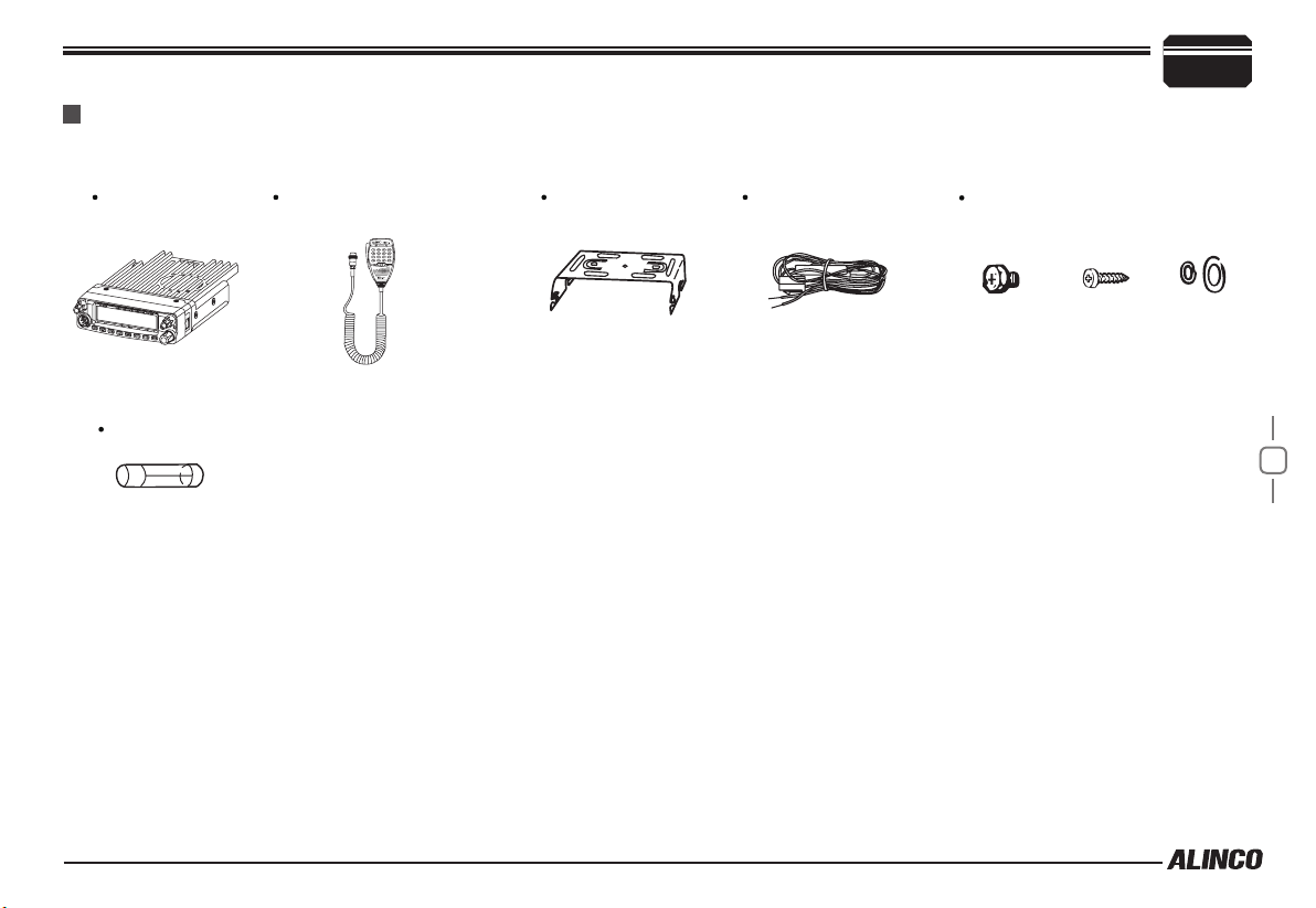
Carefully unpack to make sure the following items are found in the package in addition to this manual:
2
Transceiver
DR-638
Microphone EMS-74
(with DTMF keyboard)
Mo b i le Mo unti n g
Bracket
DC Power Cable with
Fuse Holder
Hardware Kit for Bracket
Black screws
(
M4X8mm
4PCS
Tapping screws
)
(
M5X8mm
4PCS
)
S-Washer
Spare Fuses
The standard accessories may vary slightly depending on the version you have purchased. Please contact your local authorized Alinco dealer should
you have any questions. Alinco and authorized dealers are not responsible for any typographical errors there may be in this manual. Standard
accessories may change without notice.
Warranty Policy: Please refer to any enclosed warranty information or contact your authorized Alinco dealer / distributor for the warranty policy.
■
In order to operate this product, a properly tuned antenna, its feedline with connectors and xing hardware are necessary. Please
consult with your dealer for details.
2
Page 15
3
Initial Installation
Mobile installation
The transceiver may be installed in any position in your car, where the
controls and microphone are easily accessible and it does not interfere
with the safe operation of the vehicle. If your vehicle is equipped with
air bags, be certain your radio will not interfere with their deployment. If
you are uncertain about where to mount the unit, contact your vehicle's
dealer.
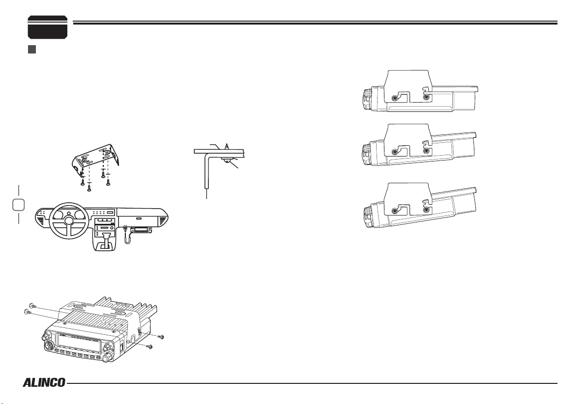
Install the mounting bracket in the vehicle using the supplied self-
1.
tapping screws (4pcs) and at washers (4pcs).
Car body
Washer (M5)
Tapping screw
(M5x20mm)
Determine the appropriate angle of the transceiver, using the 3 screw
hole positions on the side of the mounting bracket.
3
Position the transcei ver, t hen inser t and tig hten the supplied
2.
hexagon SEMS screws.
Double check that all screws are tightened to prevent vehicle
vibration from loosening the bracket or transceiver.
Mounting bracket
Caution:
Use only the provided screws
otherwise you risk damaging the
circuit board, components or falloff of the unit.
Page 16

DC Power Cable Connection
Mobile Operation
The v ehicle batter y must have a nominal ra ting of 12V. Never
connect the transceiver to a 24V battery. Be sure to use a 12V
vehicle battery that has sufficient current capacity. If the current
to the transceiver is insufficient, the display may darken during
transmission, or transmitting output power may drop excessively.
Route the DC power cable supplied with the transceiver directly
1.
to the vehicle's battery terminals using the shortest path from the
transceiver.
Never use the cigarette lighter socket as a DC source.
The entire length of the cable must be dressed so it is isolated from
heat, moisture, and the engine secondary (high voltage) ignition
system/ cables.
After installing cable, in order to avoid the risk of damp, please
2.
use heat-resistant tap to tie together with fuse box. Don't forget to
reinforce whole cable.
In or der to av oid th e r isk of sh ort ci rcu it, pl eas e c ut dow n
3.
connection with negative (-) of battery, then connect with radio.
Confirm the correct polarity of the connections, then attach the
4.
power cable to the battery terminals; red connects to the positive (+)
terminal and black connects to the negative (-) terminal.
Never remove the fuse holders from the cable.
Reconnect any wiring removed from the negative terminal.
5.
Red
Black
Initial Installation
Connect the DC power cable to the transceiver's power supply
6.
connector.
Press
If the ignition-key on/off feature is desired(optional feature),use the
optional EDC-43(For Cigar-Plug connection) cable. Connect one of the
cables between the ACC terminal or a Cigar-Plug that operates with
the vehicle ignition or ACC switch on the vehicle and EXT POWER
jack on the rear side of the unit.
When the ignition key is turned to ACC or ON(Start) position with
7.
the radio turned off, the power switch illuminates. The illumination
will be turned off when the ignition key is turned to the off position.
To turn on the unit, press the power switch manually while it is
illuminated. (While ignition key is at ACC or ON position)
When the ignition key is turned to ACC or ON position with the
8.
radio's power switch on, the unit turns on automatically and the
power switch will be lit. Turn the ignition key to OFF position or
manually turn the power switch off to shut down the radio.
Use of ignition-key ON/OFF feature drains 5mAh of current from
9.
the battery as long as the EDC-43 is being connected.
the connectors rmly together until the locking tab clicks.
DC power cable
Ext. Power jack
3
4
Page 17

3
Fixed Station Operation
In order to use this transceiver for xed station operation, you will need
a separate 13.8V DC power supply (not included) , Please contact local
dealer to require.
The current capacity of your power supply must be 12A or more.
5
Initial Installation
ACC terminal
Cigar-Plug connection
Optional EDC-43 required
Ext. Power jack
Connect the DC power cable to the regulated DC power supply
1.
and ensure that the polarities are correct. (Red: positive, Black:
negative).
Never directly connect the transceiver to an AC outlet.
Use the supplied DC power cable to connect the transceiver to a
regulated power supply.
Do not substitute a cable with smaller gauge wires.
Regulated
power supply
Black
Red
Connect the transceiver's DC power connector to the connector
2.
the DC power cable.
Press the connectors rmly together until the locking tab clicks
Before connecting the DC power to the transceiver, be sure to switch
the transceiver and the DC power supply OFF.
Do not plug the DC power supply into an AC outlet until you make all
connections.
.
REPLACING FUSES
If the fuse blows, determine the cause, then correct the problem.
After the problem is resolved, replace the fuse. If newly installed fuses
continue to blow, disconnect the power cable and contact your dealer
for assistance
Only use fuses of the sp ecified type an d rating, otherwi se the
transceiver could be damaged.
.
Fuse Location Fuse Current Rating
Transceiver 15A
Supplied Accessory DC
power cable
If you use the transceiver for a long period when th e vehicle battery is
not fully charged, or when the engine is OFF, the battery may become
discharged, and will not have sufcient reserves to start the vehicle. Avoid
using the transceiver in these conditions.
20A
on
DC power cable with fuse holder
Page 18

Power supply voltage Display
After connecting the transceiver to the power supply, long press the
key, enter 12DSPSUB menu, and select DC-IN, then it will appear
current power supply voltage on the right side of Screen.
The display immediately changes as the voltage supply changes, It also
displays voltage during transmission.
The transceiver will return to its normal operation when the power is
turned ON/OFF or repeat above operation.
Initial Installation
3
Accessories Connections
External Speaker
If you pla n to use the optional exte rnal speaker /s, The re are 2
options. For a single speaker, plug into the 3.5mm SP Jack on the
rear of the radio to hear both bands through one speaker. To use
dual speakers, use the optional Y cable and plug it into the 3.5mm ST
Jack on the rear of the radio to split the left and right bands between
the 2 speakers.
The rang e of disp la yed volt ag e is from 8V to16 V DC. Be ca us e the
displayed value is estimated, please use a voltmeter when a more precise
Important
reading is desired.
Antenna Connection
Before operating, install an efficient, well-tuned antenna. The success
of your installation will depend on the type of antenna and its correct
installation.
Use a 50Ω impedance antenna and lo w-los s coaxial feed-line that
has a characteristic impedance of 50Ω, to match the transceiver input
impedance. Coupling the antenna to the transceiver via feed-lines having
an impedance other than 50Ω reduces the efficiency of the antenna
system and can cause interference to nearby televisions, radio receivers
and other electronic equipment.
Transmitting without first connecting an antenna or other matched
load may damage the transceiver. Always connect the antenna to the
transceiver before transmitting.
All xed stations should be equipped with a lightning arrester to reduce
the risk of re, electric shock, and transceiver damage.
External speaker
6
Microphone
For voice communications, connect a provided microphone into the
socket on the front of the main unit. Turn the ring firmly on the plug
until it locks. Attach the supplied microphone hanger in an appropriate
location using the screws included in the screw set.
Microphone
connector
Page 19

3
Initial Installation
Microphone
Audio Y Cable
External Dual Speakers
(Use optional audio Y cable)
After insta lling your an tenna, ensure that you have the best
possible SWR reading.
7
IMPORTANT: RF Hazard Warning
The electro-magnetic exposure of this device may exceed the European
standards of the hazard level when transmitting at the high-power
setting while connected to a unity gain antenna at a distance of 100cm
or less from the operator. Furthermore, the hazardous RF exposure
level depends on the conditions of the combination of the antenna gain,
distance from the operator, output setting and installation environment,
the refore the operator m ay be exposed to stronger RF even at a
distance of more than 100cm. For safety purpose, it is recommended
that the antenna be installed outside of, and as far as possible from,
the operator’s area. Avoid using an excessively high-gained antenna in
case the distance between the operator and the antenna is very limited.
Always use the minimum necessary output power for communications.
External single speaker
Antenna
Page 20

Front panel
Basic Functions
NO. KEY FUNCTION
1 PWR(Power) Press it to power On/Off the transceiver.
Main AF knob
2
Sub AF knob
Main SQL ring
3
Sub SQL ring
4 Dial Knob
5 FUNC/SET
6 [V/M]
Adjust Main band audio level.
Adjust Sub band audio level.
Adjust Main band squelch level.
Adjust Sub band squelch level.
Rotate it to choose frequency/channel. Press
it to set the left band as "Main Band". In function
setup, it works as confirm key. in scan mode,
rotate it to change scan directions.
Short press:
Long press:
Short press:
memory mode.
Long press:
Function Key
Enter Function Menu setting
Switches between VFO mode and
Switch VFO working frequency
Getting Acquainted
7 [CALL]
8 [MHz]
9 [TS/DCS]
10 [H/L]
LED indicators
11
(Right/Left)
12 [SCAN]
13 [MONI]
MIC
14
Connector
15 LCD Display
4
Short press:
Long press:
Tone, press this key can edit ANI code calling
(microphone input)
Short press:
VFO mode.
Long press:
Short press:
Long press:
DCS, long press this key to open CTCSS/DCS
frequency scan.
Short press:
Long press:
I lluminates red while transmitting, green while
receiving signals.
Short press:
Long press:
O p e n s s q u el c h a n d c a nc e l s TS Q / D C S
temporary.
connect the mic connector or data reading/writing,
cloning
Di s pla y s f r equ e nci e s, chann els and othe r
operating parameters.
Switches to CALL channel.
when channel setting DTMF/5
Changes frequency step by 1MHz in
Open the scrambling function.
Sets CTCSS and DCS values.
when channel setting CTCSS/
Switches the output power
Open the emergency alarm function
Starts scanning.
DTMF/2TONE/5TONE setting
8
Page 21

4
Functions
Getting Acquainted
which can be activated while appears, after pressing the
Key
1 MW FUNC+
2 DEL FUNC+
3 SHIFT FUNC+
LOCK
4
5 PRI FUNC+
6 SKIP FUNC+
7 FUNC+
FUNC+
V/M
CALL
MHZ
TS/DOS
H/L
SCAN
MONI
Programs the data into the memory.
Delete settings.
Changes shift directions.
Blocks the keys and dial operation
Enters to the Priority monitor.
Sets scan skip channels
Setting memory banks.
DISPLAY
1 2 3 4 5 6 7 8 13 9 14 10 15 11 1712
19
20
21
252622 23 24 25
18
16
27
Rear panel
21
4 5
9
NO. KEY FUNCTION
Ext. Power
1
Jack
Ext.Speaker
2
Terminal
Antenna
3
Connector
Ext.Single
4
Speaker Port
To Connect optional cable for ignition key On/Off
function.
To Connect an optional external speaker.
Connect a 50 Ω antenna
Terminal for optional single external speaker.
5 Fan Runs Automatically when radio temperature rise up.
3
NO. KEY
1
2
3
4
5
6
7
DCS
8
COMP
9
10
REP
11
12
SUB
13
14
15
16
Å
FUNCTION
Appears when press FUNC key.
Appears while in AM mode.
Appears while using Middle output power.
Appears while using low output power.
Appears while channel setting in narrow band.
Appears while channel setting in offset direction.
Appears while channel setting in CTCSS encoding and decoding
Appears while channel setting in DCS encoding and decoding.
Appears while channels setting in voice companding.
Appears while open key lock function.
Appears while open Cross repeat.
no function at present.
Appears while SUB band in Main side.
Appears while Channels setting in Scrambler.
Appears while open grouping function.
Appears while Sub side in memory channel or Call channel mode.
Page 22

17
18
19
20
MAIN
21
P1
22
P2
23
P3
24
25
26
27
microphone
Appears while Channels setting in scrambling function.
no function at present.
Appears channel frequency or channel name.
Appears channel number or grouping number.
Appears while Main band.
Appears when current channel is priority channel.
Appears while channel setting in Scan skip.
Flash while open Scan.
Appears while main/sub receive squelch opened.
MAIN:Transmit power indicator/receive indicator.
SUB:Transmit power indicator/receive indicator.
8
9
1
10
Getting Acquainted
PA Switches between VFO and Memory modes.
PB Changes CTCSS and DCS mode parameters.
3
PC Starts and stops scanning.
PD Transmit preprogrammed DTMF, 2TONE, 5TONE code.
Band Indicator The indicator light on for Main band.
4
TX/RX Indicator
5
(Main/Sub)
PTT
6
UP
7
DOWN
8
MIC Speak here during transmission.
9
Speaker
10
MIC Connector Diagram(in the front view of connector)
Illuminates red while transmitting, green while receiving
signals.
Push-TO-Talk key: Press this key to transmit.
Increase frequency ,channel number or setting value.
Decrease frequency, channel number or setting value.
When shut the speaker in the base, you can hear the
calling by this speaker.
4
10
NO. KEY FUNCTION
M/S
1
Number Key
2
Switches between Main and Sub bands.
Input VFO frequency or DTMF dial out etc.
Page 23

5
Important: The explanations herein are based on manufacturer's default
setting.
Landmobile units may be programmed differently.
Basic Operations
and Memory mode. When in memory mode,
the memory channel number appears on the
left side of memory frequency.
Switching The Power On/Off
Power On
Press key to turn on. Appears "ALINCO DR638" then displays current frequency or channel.
Power Off
Press
key for over 0.5 Second to turn off.
POWER
Adjusting The Volume
Rotate the [VOL] knob of selected band clockwise
to increase the audio level, counterclockwise to
decrease.
11
Rotate the SQL ring counterclockwise to hear the white noise to set the audio
level properly.
SQUELCH LEVEL SETTING
Rotate the [SQL] ring of selected band clockwise
to increase the squelch level,counterclockwise to
decrease.
A noise is heard at the minimum setting.
Squelch is to cut the white-noise in stand-by state.
Setting it too high may risk missing weaker signals but lower setting may
open squelch often hearing more noise. You should set the levels of both
MAIN and SUB bands before start operating.
Switch between VFO and MEMORY MODE
In standby, press or key to switch between VFO(Frequency)
Setting Frequency
In VFO mode, turn the dial clockwise to increase
frequency; Counterclockwise to decrease. Every
click will increase or decrease frequency by one
channel-step. To select MAIN and SUB band,
press the dial. Press key then turn the dial
or [UP/DOWN] keys to change the frequency by
1MHz step.
The microphone
Press
[UP/DOWN]
size. Hold
[UP/DOWN]
[UP/DOWN]
key will increase(decrease) the frequency by one step
key also able to adjust frequency.
key will adjust the frequency continuously.
Input Frequency THROUGH Microphone number key
In VFO mode, you can input the frequency by the numerical keys.
Out-of-the-band frequnecies are automatically rejected.
For example, to input 145.320MHz, press 1,4,5,3,2,0 sucsessively.
When completed, a decimal point appears at the MHz order.
Setting CHANNEL
In memory mode, you can select the frequency by turning the dial.
Turn clockwise to increase,counterclockwise to decrease the channel
numbers. To switch the MAIN/SUB band, press the dial.
While a memory channel is shown in SUB band, [
]icon appears.
Page 24

Basic Operations
Pressing [UP/DOWN] keys on microphone also sets channels. Some restriction may apply depending on the versions. Transmitting is
The mamory channels must be pre-programmed to operate in the memory
mode. Empty channels numbers won't be displayed during operation and
appears only during memory setting.
Input Channel THROUGH Microphone number key
In memory mode, pressing 3 numerical keys recalls the desired memory
channel. For example press 0,0,1 recalls channel 1. Press 0,3,0 for
ch.30, and 5,1,2 for ch.512. If the input channel is not programmed in
advance, an error beep sounds and returns to last channel operated.
While pressing the key, [CH-] and entering numbers are shown on the
display.
Switch Between Main Band and Sub band
At the default setting, both MAIN and SUB
ba nds a re dis pla yed. The t ran smi tti ng is
possible only on the frequency/channel shown
on the LEFT.
To transmit, press the dial to set the desired
frequency or channel on the LEFT side of the
display.
SELECTING THE OPERATING BAND
1. Select the MAIN band by pressing the dial so that MAIN appears on
the left corner of the display. By pressing and holding the
toggles the operating bands between 108-180MHz, 220-260MHz, 350-
399MHz and 400-480MHz for receiving.
2.S elect the SUB band so that SUB app ears above the frequen cy
display on the right. By pressing and holding the key toggles the
operating bands between 136-174MH and 400-480MHz for transmitting.
key
prohibited outside of the specied frequency range. "OFF" appears when
PTT is pressed in the RX-only frequency and alarming beep sounds.
This transceiver can be set working on 2 UHF band or 2 VHF
band.
Receiving
Both MAIN and SUB bands receive s ignals simu ltaneously. While
receiving signals, the
strength icon will appear in the display, and
audio sounds.
You m a y r isk mis sing we aker si gnal s w hen the squ elch
level is set too high. If the Busy and signal strength icon are
displayed but can't hear any audio, please check the selective
calling(signaling) setting like Tone-squelch and DCS.
icon and signal
Squelch Off/Squelch Off Momentary
Press and hold
temporary to monitor incoming signals of currently operating band.
Release the
and signaling settings.
Pressing [ ] key on the microphone functions
same as above but holds squelch off until the [ ] is pressed again.
key cancels the squelch and signaling setting
key to activate the squelch
5
12
Page 25

5
Basic Operations
Transmitting
Before transmitting, monitor the frequnecy to make sure the channel is
vacant and won't cause interference to others.
Hold [PT T] key to t ra nsmit, and speak at
approximately 5cm/2 inces to the microphone
in normal voice level. Too loud or too silent
voice level may cause trouble hearing at the receiving stations.
Transmitting is possibl e only on the MAIN band. Operating
setting can't be changed while transmitting.
Transmit DTMF/2TONE/5TONE signaling
If the current channel is with DTMF/2TONE/5TONE signaling, hold [PTT]
and [ UP ] key will transmit selected Pre-programmed signaling.
13
Power SETTING
Press
press of the key toggles the setting as the chart below.
The setting is valid until next change in VFO mode, but it holds only
temporaly in the memory mode and changing the channel or turning
on/off the power will cancel the setting and recalls the original memory
parameter of the output power setting.
HIGH
VHF(50W)
UHF(40W)
key to choose output power from different levels. Every
Frequency Reverse
In standby, hold key for over 1 second to turn On/Off frequency
reverse function. When reverse function is on, the TX frequency will
change to RX frequency and RX frequency change to TX frequency.
The signaling will also be reversed if CTCSS/DCS signaling existed in
this channel.
This function is valid only when current channel setup with offset
frequency and offset direction
CTCSS/DCS SETTING
In standby, press key or microphone ke y can setting the
CTCSS/DCS encoding and decoding for current channel.
Press
1.
and " " icon, rotate band switch or MIC UP/DOWN keys to select
CTCSS encoding which is desired to setting, press key or [PTT]
key to conrm and exit.
Double Press
2.
frequency and "
keys can sync setting the CTCSS encoding and decoding which is
desired, press
Press
3.
and "DCS" icon, rotate band switch or MIC UP/DOWN keys can sync
select the CTCSS encoding and decoding which is desired, press
key, When the screen displays the CTCSS frequency
ke y, When the screen di splays the CTCSS
" icon, rotate band switch or MIC UP/DOWN
key or [PTT] key to conrm and exit
key three times, When the screen displays the DCS NO.
key or [PTT] key to conrm and exit.
CALL CHANNEL RECALLING
Press key to recall a preprogrammed channel. It is convenient to
set the most frequently used channel in advance as a CALL channel for
quicker operation.Repeat it to return to the
last operating channel.
Page 26

CTCSS/DCS Scan
In standby, long press key to enter CTCSS/DCS scan, when nd
matching CTCSS/DCS signal, the scan will pause in the scan pause
way. In the CTCSS/DCS Scan status, rotate band switch or press the
MIC UP/DOWN key can change the scan direction.
To enable this function, the channel shall be programmed with
CTCSS/DCS decode.
DUAL WATCH
In standby, Press and while icon is displayed on the screen,
press key to enter Dual Watch mode. The radio will scan the
channel in every 5 seconds. When the radio receives matching signal, it
pause scanning until the signaling disappear. Repeat above operation to
exit Dual watch.
EMERGENCY ALARM
To start emergency alarm, press and hold key until the trans
-ceiver displays ALARM and emit alarm. Re-power on the transceiver to
exit alarm. This transceiver has 4 kind of alarm which can be setup by
programming software.
CHANNEL/FREQUENCY SCAN
FREQUENCY SCAN
In VFO mode, press the or key to start scanning.
During the scanning, turn the dial or press [UP/DOWN] keys to change
the scanning direction. Press [PTT] or keys other than [UP/DOWN] to
stop scanning.
Basic Operations
5
CHANNEL SCAN
In Memory mode,press the or key to start scanning.
During the scanning,turn the dial or press [UP/DOWN] keys to change
the scanning direction. Press [PTT] or keys other than [UP/DOWN] to
stop scanning.
CHANNEL SCAN SKIP
In Memory mode, turn the dial to choose the channel to skip during
scanning. Press and while icon is displayed on the screen,
press key. A beep sounds twice and the
channel is set as the skip channel and "P2"
icon. Repeat it to cancel the setting, a beep is
heard once and "P2" icon dissapears.
MEMORY CHANNEL PROGRAMMING
In VFO mode, select the desired frequency by using the dial or
1.
numerical keys.
Press
2.
display.
Rotate the dial or press
3.
memory channel number.
While displaying the
4.
appears on the display. While it's displayed, press and hold the
key again until a beep is heard and MEN-IN dissapears. The memory
channel is set. If icon dissapears during operation, simply press
the key again to resume.
key to display and a memory channel number on the
[UP/DOWN] keys to se le ct a desired
and a number, press key. MEN-IN
SEARCH SCAN RANGE SETTING
Five different search scan ranges are programmable.
14
Page 27

5
Set a pair of upper and lower limit frequencies in each L1/U1- L5/
U5 memory channels to activate the function. L stands for the lower
and U stands for the upper limit. The upper
limit must exceed the lower limit frequency.
Please refer above "MEMORY CHANNEL
PROGRAMMING" section for how to memory frequencies.
Basic Operations
CHANNEL COPY
In memory mode, select the desired channel by using the dial or
1.
numerical keys.
Press
2.
display.
Rotate the dial or press
3.
memory channel number.
While displaying the
4.
15
press key. MEN-IN appears on the
display. Two beep is heard and then MEN-IN dissapears. channel
copy completed. If icon disappears during operation, simply press
the
key to display and a memory channel number on the
[UP/DOWN] keys to se le ct a desired
and a number,
key again to resume.
CHANNEL DELETE
1.In memory mode, select the desired channel by using the dial or
1.
numerical keys.
Press
2.
on the display. A beep is heard and the memory channel frequency
disappears
Then rotate the dial or press
3.
DOWN] keys to confirm, channel delete
completed. If
operation, simply press the key
again to resume.
key to display then press key. MENOUT appears
[UP/
icon dissapears during
MEMORY BANKS OPERATION
The transceiver has 6 groups “A-F” and one no edit group.
Normal memory: 1 to 200 (200ch)
Bank A: CH 201 to 300 (100ch)
Bank B: CH 301 to 400 (100ch)
Bank C: CH 401 to 500 (100ch)
Bank D: CH 501 to 600 (100ch)
Bank E: CH 601 to 700(100ch)
Bank F: CH 701 to 758 (58ch)
In memory mode, you can do the groups function according to the
following instruction, the groups number show in the position of channel
number. Normal memory: show “- -”.
Press
1.
mode.
Rotating the dial to choose the groups you want.
2.
Press the
3.
icon appears on the display, then the radio
goes to the group that you choose.
If there is not channel in your choose group, it will return to the
original channel.
Exit the groups mode: Press the
4.
times continuously, "
channel mode.
key to display then press key to enter the group
key again to conrm, " "
then press key in two
" icon disappears, the radio will back to the
Page 28
Parameter Setting Mode (SET MODE)
You can set the operating parameters and functions of DR-638 to best
suite your demands.
Press and hold
1.
Rotate the dial or use
2.
Press the dial to enter to the parameter setting state and rotate it or
3.
use [UP/DOWN] keys to select the desired value.
Press the dial again to go back to the menu and set next parameters,
4.
or press [PTT] or key to set the new parameter and return to
the operating mode.
MENU 01: APO (AUTOMATIC POWER OFF)
Once APO is activated, the transceiver will be automatically switched off
when the pre-set time is elapsed.
Press and hold
1.
the function menu.Rotate the dial or use
[UP/DOWN] keys to select the menu 01
APO and press the dial.
Rotate the dial or use
2.
select the value from 0.5 to 12 hours, or
OFF for not using this function.
Press [PTT] to set and exit or press the dial to set and continue.
3.
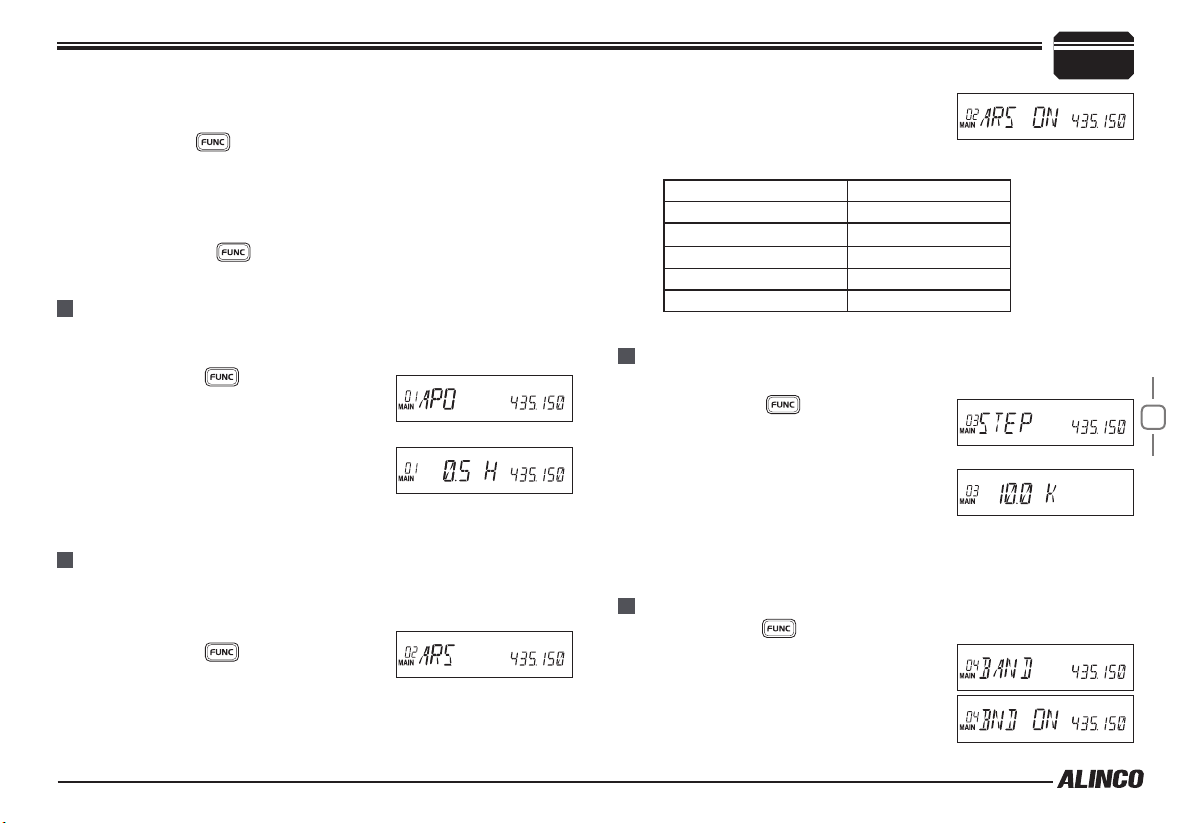
MENU 02: AUTOMATIC OFFSET
This transceiver has automatic offset function. When this function is on,
the transceiver will automatically transmitting with RX frequency ± offset
frequency.
Press and hold
1.
the function menu.Rotate the dial or use
[UP/DOWN] keys to select the menu 02 ARS and press the dial.
Rotate the dial or use
2.
Press [PTT] to set and exit or press the dial to set and continue.
3.
key until activating the function menu.
[UP/DOWN] keys to select the desired menu.
key until activating
[UP/DOWN] keys to
key until activating
[UP/DOWN] keys to select ON or OFF.
When the ARS is ON, the transceiver will
4.
automatically turn on offset direction, the
default offset for 144MHz range is 0.6MHz,
and 440MHz range is 5MHz.
Frequency range Offset Direction
145.200-145.495MHz LCD displays "-"
146.610-146.995MHz LCD displays "-"
147.000-147.395MHz LCD displays "+"
442.000-444.995MHz LCD displays "+"
447.000-449.995MHz LCD displays "-"
MENU 03: VFO CHANNEL STEP SETTING
This menu appears only in the VFO mode.
Press and hold
1.
the function menu.Rotate the dial or use
[UP/DOWN] keys to select the menu 03
STEP and press the dial.
Rotate the dial or use
2.
to select the value from 2.5K, 5K, 6.25K,
10K, 12.5K
Press [PTT] to set and exit or press the dial to set and continue.
3.
key until activating
[UP/DOWN] keys
MENU 04: VFO BAND LOCKOUT
Press and hold
1.
the dial or use [UP/DOWN] keys to select
the menu 04 BAND and press the dial.
Rotate the dial or use
2.
select the value from
ON: Turn on VFO band lockout function
key until activating the function menu. Rotate
[UP/DOWN] keys to
6
16
Page 29

6
OFF: Turn off VFO band lockout function
The scanning or frequency setting through the dial or numerical keys
3.
become available only within the current VFO frequency band.
Press [PTT] to set and exit or press the dial to set and continue.
4.
Parameter Setting Mode (SET MODE)
MENU 05: BEEP SOUND
Press and hold
1.
the dial or use [UP/DOWN] keys to select the menu 05 BEEP and
press the dial.
Rotate the dial or use
2.
select the value from
ON: Turn on Beep function.
3.
OFF: Turn off Beep function.
OFF setting turns off the beep sounds.
17
Press [PTT] to set and exit or press the dial to set and continue.
4.
key until activating the function menu.Rotate
[UP/DOWN] keys to
MENU 06: CPU CLOCK FREQUENCY SETTING
Press and hold
1.
the dial or use [UP/DOWN] keys to select
the menu 06 CLKSFT and press the dial.
Rotate the dial or use
2.
select the value from
ON: Change CPU clock.
OFF: CPU clock frequency remain unchanged.
When you hear a noise-interference always on a certain same
3.
channel even without connecting to the antenna, try setting it to ON
parameter. If the noise is CPU clock related, it may be eliminated.
This feature is not a noise-blanker.
Press [PTT] to set and exit or press the dial to set and continue.
4.
key until activating the function menu. Rotate
[UP/DOWN] keys to
MENU 07: 2TONE ENCODE SELECT
Press and hold
1.
the dial or use [UP/DOWN] keys to select the menu 07 2T ENC and
press the dial.
Rotate the dial or use
2.
select the value from 0-23, total 24 groups.
If the 2TONE encode are programmed
wi t h nam e , the LCD wi ll d i s play the
correspondent name.
Press [PTT] to set and exit or press the dial to set and continue.
3.
After choose the 2TONE encode group. Press [PTT] will transmit selected
NOTE
code.
key until activating the function menu. Rotate
[UP/DOWN] keys to
MENU 08: 5TONE ENCODE SELECT
Press and hold
1.
the dial or use [UP/DOWN] keys to select
the menu 08 5T ENC and press the dial.
Rotate the dial or use
2.
to select the value from 0-99, total 100
groups.
If the 5TONE encode are programmed with name, the LCD will
display the correspondent name.
Press [PTT] to set and exit or press the dial to set and continue.
3.
After choose the 5TONE encode group. Press [PTT] will transmit selected
N
OTE
code.
key until activating the function menu. Rotate
[UP/DOWN] keys
Page 30

MENU 09: ADD OPTIONAL SIGNALING
Press and hold
1.
the dial or use [UP/DOWN] keys to select
the menu 09 TONDEC and press the dial.
Rotate the dial or use
2.
select the value from :
DTMF: means DTMF signaling is added.
2TONE: means DTMF signaling is added.
5TONE: means DTMF signaling is added.
OFF: Turn off optional signaling
Press [PTT] to set and exit or press the
3.
dial to set and continue.
DTMF and 5Tone signaling can be applied
4.
for other advanced features such as ANI, [PTT] ID, group call, select
call, remotely stun, remotely kill/Revive etc.
The working of optional signaling shall be work associated with the squelch
OTE
N
mode setup. (Refer to Squelch Mode setup in page 20)
key until activating the function menu.Rotate
[UP/DOWN] keys to
MENU 10: TONE ENCODE SETUP
Press and hold
1.
dial or use [UP/DOWN] keys to select the
menu 10 TXCDCS and press the dial.
Rotate the dial or use
2.
select the value from:
OFF: Turn off both CTCSS/DCS encode.
CTCSS: Set CTCSS encode.
DCS: Set DCS encode.
key until activating the function menu.Rotate the
[UP/DOWN] keys to
Parameter Setting Mode (SET MODE)
Press PTT to set and exit or press the dial to set and continue.
3.
Available tones
CTCSS: 62.5-254.1Hz, and one self-
dene group, total 52 groups
DCS: 000N-777I, total 1024 groups
See the Appendix at the end of this booklet
4.
for more details.
MENU 11: TONE DECODE SETUP
Press and hold
1.
dial or use [UP/DOWN] keys to select the menu 11 RXCDCS and press
the dial.
Rotate the dial or use
2.
select the value from:
OFF: Turn off both CTCSS/DCS decode.
CTCSS: Set CTCSS decode.
DCS: Set DCS decode.
Press [PTT] to set and exit or press the
3.
dial to set and continue.
Available tones
CTCSS: 62.5-254.1Hz, and one self-
dene group, total 52 groups
DCS: 000N-777I, total 1024 groups
See the Appendix at the end of this booklet
for more details.
The working of CTCSS/DCS decode shall be work associated with the
N
OTE
squelch mode setup. (Refer to Squelch Mode setup in page 19)
key until activating the function menu.Rotate the
[UP/DOWN] keys to
6
18
Page 31

6
Parameter Setting Mode (SET MODE)
MENU 12: SUB BAND DISPLAY
Press and hold
1.
dial or use [UP/DOWN] keys to select the
menu 12 DSPSUB and press the dial.
Rotate the dial or use
2.
select the value from:
FREQ: Displays sub band frequency.
DC-IN: Displays approximate DC voltage
instead of sub band frequency.
OFF: Turns off to display the sub band
frequnecy.
Press [PTT] to set and exit or press the
3.
dial to set and continue.
While OFF is selected, you can still switch beteen the MAIN and
4.
SUB bands.
19
This setting only hides the SUB band appearance, not turning off the
5.
SUB band functions.
key until activating the function menu.Rotate the
[UP/DOWN] keys to
MENU 13: DTMF ENCODE PRE-LOADING TIMING
Press and hold
1.
the dial or use [UP/DOWN] keys to select the menu 13 DTMF D and
press the dial.
Rotate the dial or use
2.
select the pre-Loading time value from:
1 0 0M s/ 3 00 Ms /6 0 0M s/ 8 00 Ms a n d
1000Ms(1 second)
Press [PTT] to set and exit or press the dial to set and continue.
3.
key until activating the function menu.Rotate
[UP/DOWN] keys to
MENU 14: DTMF ENCODE TRANSMITTING TIME
Press and hold
1.
the dial or use [UP/DOWN] keys to select the menu 14 DTMF S and
press the dial.
Rotate the dial or use
2.
select the time for transmit a single DTMF
encoding tone and the interval time value
from 30Ms / 50Ms / 80Ms / 100Ms / 150Ms
/ 200Ms and 250Ms.
Press [PTT] to set and exit or press the dial to set and continue.
3.
key until activating the function menu. Rotate
[UP/DOWN] keys to
MENU 15: DTMF ENCODE SETUP
Press and hold
1.
dial or use [UP/DOWN] keys to select the
menu 15 DTMF W and press the dial.
Rotate the dial or use
2.
select the DTMF group.
Press
3.
Pressing [PTT] will transmit with selected
DTMF code (01-16: 16 groups of DTMF
codes programmable). When the selected
group is empty, the LCD displays [------].
Press the dial so that the last bar starts
flashing. Turn the dial to select desired
rst character or number for DTMF tone coding.Press the dial again
to select the next. Press the key to complete and return to the
DTMF group menu. Repeat for more coding.
Press
4.
Press [PTT] to set and exit or press the dial to set and continue.
5.
key again to go back to DTMF.
key again to store values and exit code editing.
key until activating the function menu.Rotate the
[UP/DOWN] keys to
Page 32

MENU 16: SQUELCH MODE SETUP
This parameter becomes available only when CTCSS/DCS or optional
DTMF/5TONE/TONE signaling has been set.
Press and hold
1.
the function menu.Rotate the dial or use
[UP/DOWN] keys to select the menu 16 SGN SQL and press the
dial.
Rotate the dial or use
2.
select desired setting.
SQ: Norma l squel ch only w it hout any
selective calling functions.
CTSS/DCS: Like TSQ or DCS, CTCSS/
DCS code is required to open the squelch.
CT*TO: O p t i o n a l si g n a l i n g su c h as
DTMF and 5-tone is required to open the
squelch.
TONE: CTC SS/ DCS an d an Opt ion al
signaling is required to open the squelch.
CT/TO: Opens squelch when matching
either one of CTCSS/DCS or an optional signaling.
Press [PTT] to set and exit or press the dial to set and continue.
3.
key until activating
[UP/DOWN] keys to
MENU 17: COMPANDER
Compander reduces background noise, but all users' radios must be
equipped with compander and turned on the function.
Press and hold
1.
the function menu. Rotate the dial or use
[UP/DOWN] keys to select the menu 17
COMP and press the dial.
Rotate the dial or use
2.
key until activating
[UP/DOWN] keys to select the value:
Parameter Setting Mode (SET MODE)
ON: Turn on Compander function.
OFF: Turn off Compander function
Press [PTT] to set and exit or press the
3.
dial to set and continue.
MENU 18: SCRAMBLER (AVAILABLE TO COMMERCIAL MODELS ONLY)
Analog inversion scrambling is available to
commercial-use versions only.
Press and hold
1.
the function menu. Rotate the dial or use [UP/DOWN] keys to select
the menu 18 SCR and press the dial.
Rotate the dial or use
2.
to select the value. Available parameters
are 1-9 (9 fixed groups )U1, U2 (2 self
dened scrambler groups). Set the same value to all users.
Press [PTT] to set and exit or press the dial to set and continue.
3.
key until activating
[UP/DOWN] keys
MENU 19: TONE BURST TONES
Tone-burst tones are commonly used in Europe to activate repeaters.
Press and hold
1.
the function menu.Rotate the dial or use
[UP/DOWN] keys to select the menu 19
TBST and press the dial.
Rotate the dial or use
2.
select desired setting.
1000: 1000Hz.
1450: 1450Hz.
1750: 1750Hz.
2100: 2100Hz.
Press [PTT] to set and exit or press the dial to set and continue.
3.
key until activating
[UP/DOWN] keys to
6
20
Page 33

Parameter Setting Mode (SET MODE)
6
To send the tone, press [PTT] then press [down] key. Once the
repeater is open, sending TBT is not necessary.
MENU 20: HYPER
The radio can be setting two kinds of display mode,HYPER1 and
HYPER2, Provide independent VFO, Call Channel, Group function
setting.
Press and hold key until activating the
1.
function menu.Rotate thedial or use
DOWN]
keys to select the menu 20 HYPER and pressthe dial.
Rotate the dial or use
2.
select desired setting.
HYPER1:Super channel 1 display mode.
HYPER2:Super channel 2 display mode.
21
Press [PTT] to set and exit or press the
3.
dial to set and continue.
[UP/DOWN]
[UP/
keys to
MENU 21: KEYPAD LOCKOUT
Press and hold
1.
dial or use [UP/DOWN] keys to select the
menu 21 LOCK and press the dial.
Rotate the dial or use
2.
select the value:
ON: T u r n on th e ke y - l o c k . A l l ke y s
operation are locked except
OFF: Turn off the key-lock.
Press [PTT] to set and exit or press the dial to set and continue.
3.
key until activating the function menu.Rotate the
[UP/DOWN] keys to
key.
MENU 22: PTT LOCKOUT
This function is to prohibit or restrict PTT operations.
Press and hold
1.
dial or use [UP/DOWN] keys to select the
menu 22 LOCKT and press the dial.
Rotate the dial or use
2.
select the value:
ON: PTT lock.
OFF: PTT lock disabled.
3.
Press
key to set and exit or press the dial to set and continue.
key until activating the function menu.Rotate the
[UP/DOWN] keys to
MENU 23: TOT PENALTY
When transmission is shut down in the TOT mode, this function prohibits
another transmission during a selected TOT penalty period regardless
of the [PTT] key being pressed. A beep sounds when the [PTT] key is
pressed during the TOT penalty period.
Press and hold key until activating the function menu. Rotate the
1.
dial or use [UP/DOWN] keys to select the
menu 23 TOTP and press the dial.
Rotate the dial or use
2.
select the value:
1-30 second, total of 30 setting parameters
OFF: TOTP is turn off.
Press [
3.
PTT] to set and exit or press the dial to set and continue.
[UP/DOWN] keys to
MENU 24: TALK AROUND
Press and hold
1.
the function menu.Rotate the dial or use
[UP/DOWN] keys to select the menu 24
key until activating
Page 34

REV and press the dial.
Rotate the dial or use
2.
ON: Talk Around is turn on. The TX and
RX frequency will be reversed, along with
the CTCSS/ DC S encode and deco de
frequencies if used.
OFF: Turn off Talk Around
Press [
3.
PTT] to set and exit or press the dial to set and continue.
[UP/DOWN] keys to select the value:
MENU 25: SUB BAND MUTE
Press and hold
1.
dial or use [UP/DOWN] keys to select the
menu 25 MUTE and press the dial.
Rotate the dial or use
2.
select the value:
TX: When the Main band is transmitting,
the sub band receive is mute.
RX: When the Main band is receiving, the
sub band receive is mute.
RX/TX: Suspends the sub band receive at
any time.
Press [
3.
PTT] to set and exit or press the dial to set and continue.
key until activating the function menu.Rotate the
[UP/DOWN] keys to
Parameter Setting Mode (SET MODE)
Turn the dial to select desired first
2.
character.Press the dial again to edit the
next. Press
exit the setting menu.
Press PTT to set and exit or press the dial to set and continue.
3.
key to store values and
MENU 27: TIME-OUT TIMER(TOT)
The time-out timer limits the amount of continuously transmitting time.
When the transmitting reaches the selected TOT value, the transmission
will be automatically cut off and emits warning beep.
Press and hold
1.
the dial or use [UP/DOWN] keys to select the menu 27 TOT and
press the dial.
Rotate the dial or use
2.
select the value:
1-30 Minutes, total of 30 setting
parameters.
OFF: TOT is turn off.
Press [
3.
OTE
N
PTT] to set and exit or press the dial to set and continue.
4-5 minutes is common and recommended.
key until activating the function menu.Rotate
[UP/DOWN] keys to
6
22
MENU 26: EDITING MEMORY NAME
Press and hold
1.
the dial or use [UP/DOWN] keys to select
the menu 26 NAME C and press the dial
so that the last digit starts ashing. Up to 7
characters can be registered in each memory channel.
key until activating the function menu.Rotate
MENU 28-31: MICROPHONE PA,PB, PC,PD KEY SETUP
Press and hold
1.
the function menu.Rotate the dial or use
[UP/DOWN] k eys to sele c t t heme nu
No.28-31 menu The LCD displays "PG
PA", "PG PB", "PG PC", "PG PD". and
press the dial.
key until activating
Page 35

6
Rotate the dial or use
2.
Press
3.
N
OTE
Parameter Setting Mode (SET MODE)
[UP/DOWN] keys to select wanted value
[PTT] to set and exit or press the dial to set and continue.
For Menu details, please refer to Page 29-30, Microphone Operation.
MENU 32: RF SQUELCH
The squelch opens only when the signal strength reaches to the selected
S-meter reading.
Press and hold
1.
the function menu.Rotate the dial or use
[UP/DOWN] keys to select the menu 32 RF SQL and press the dial.
Rotate the dial or use
2.
S-3: Squelch opens at 3 bar.
S-5: Squelch opens at 5 bars.
23
S-9: Squelch opens at 9 bars.
S-FULL: Squelch opens at FULL-scale
reading only.
PTT] to set and exit or press the dial to set and continue.
Press [
3.
when open, SQL ring adjustment is inefficiency.
NOTE
key until activating
[UP/DOWN] keys to select the value:
MENU 33: OFFSET DIRECTION
Press and hold
1.
dial or use [UP/DOWN] keys to select the
menu 33 RPT MOD and press the dial.
Rotate the dial or use
2.
to select the value:
key until activating the function menu.Rotate the
[UP/DOWN] keys
-: M i n u s offs e t , me ans t r a n s m itting
fr e quen c y is lower than recei v ing
frequency.
+: Plus offset, me a n s tr a n s m i t t i n g
fre quency is high er than receiving
frequency.
OFF: OFFSET is turn off. Transmitt ing
fre q u e n c y is the sam e as re c e iving
frequency.
Press [
3.
PTT] to set and exit or press the
dial to set and continue.
MENU 34: SCAN RESUME CONDITION
Press and hold
1.
the function menu.Rotate the dial or use
[UP/DOWN] keys to select the menu 34
SCAN and press the dial.
Rotate the dial or use
2.
to select the value:
TIME: Pauses 5 seconds to receive the
signal and resume scanning.
BUSY: Remains on the frequency until
the signal is gone, then resume scanning
after pausing 2 seconds.
SECEDE: Can ce ls scannin g when a
signal is received and stopped scanning.
Press [
3.
PTT] to set and exit or press the
dial to set and continue.
key until activating
[UP/DOWN] keys
Page 36

MENU 35: PRIORITY CHANNEL SCAN
Priority channels must be pre-programmed in P SCAN to set this
parameter.
Press and hold
1.
dial or use [UP/DOWN] keys to select the
menu 35 SCAN M and press the dial.
Rotate the dial or use
2.
to select the value:
MEN: Scans all memory channels in the
channel scanning mode.
MSN: Scan s on l y Pr i o rity me m o r y
channels in the channel scanning mode.
Press [
3.
PTT] to set and exit or press the dial to set and continue.
key until activating the function menu.Rotate the
[UP/DOWN] keys
MENU 36: OFFSET FREQUENCY
The difference between the transmitting and receiving frequencies for
repeater operation is called shift or offset frequnecy.
Press and hold
1.
the function menu.Rotate the dial or use
[UP/DOWN] keys to select the menu 36
SHIFT and press the dial.
Rotate the dial or use
2.
to select desired value between 0 and
100MHz.
Press [
3.
PTT] to set and exit or press the dial to set and continue.
key until activating
[UP/DOWN] keys
MENU 37: DISPLAY MODE
Press and hold
1.
the function menu. Rotate the dial or use
key until activating
Parameter Setting Mode (SET MODE)
[UP/DOWN] keys to select the menu 37 DISPLAY and press the dial.
Rotate the dial or use
2.
FREQ: D i s p l ays c h a n nel n u m b er +
frequency in memory mode and switches
to VFO mode by pressing key.
CH: D i spla y s on l y mem o ry c h anne l
numbers.
NAME: Displays channel number + name
tags in memory mode and switches to
VFO mode by pressing
Press [
3.
PTT] to set and exit or press the dial to set and continue.
[UP/DOWN] keys to select the mode:
key.
MENU 38: BUSY CHANNEL LOCKOUT(BCLO)
Press and hold
1.
the function menu.Rotate the dial or use
[UP/DOWN] keys to select the menu 38
REPLOCK and press the dial.
Rotate the dial or use
2.
RLORP: Signal in g BCLO , transmitting
is inhibited when a signal with different
CTCSS/DCS setting is being received.
RLOBU: Transmitting is inhibited when a
signal of any kind is being received.
OFF: BCLO is disabled.Transmitting is
allowed in any receiving status.
PTT] to set and exit or press the dial to set and continue.
Press [
3.
key until activating
[UP/DOWN] keys to select the mode:
MENU 39: DTMF SELF ID ENQUIRY
Press and hold
1.
the dial or use [UP/DOWN] keys to select the menu 39 DTMF ID and
key until activating the function menu.Rotate
6
24
Page 37

6
press the dial.
The DTMF self ID is shown on the display.
2.
Press [
3.
dial to set and continue.
Parameter Setting Mode (SET MODE)
PTT] to set and exit or press the
MENU 40: 5-TONE SELF ID ENQUIRY
Press and hold
1.
dial or use [UP/DOWN] keys to select the
menu 40 5TONE ID and press the dial.
The 5-TONE self ID is shown on the
2.
display.
Press [
3.
25
PTT] to set and exit or press the
dial to set and continue.
key until activating the function menu.Rotate the
MENU 41: VFO FREQUENCY LINKAGE
Press and hold
1.
dial or use [UP/DOWN] keys to select the
menu 41 VFOTR and press the dial.
Rotate the dial or use
2.
select the value:
ON: Turn on the Link. In VFO mode, both
MA IN a nd SUB band fr e que nci e s
changes by the same channel steps at
dial or [UP/DOWN] operation.
OFF: Turn off the Link.
Press [
3.
OTE
N
PTT] to set and exit or press the dial to set and continue.
This function is valid only when both bands operate in VFO mode.
key until activating the function menu.Rotate the
[UP/DOWN] keys to
42: NARROW FM MODE
MENU
Press and hold
1.
dial or use [UP/DOWN] keys to select the
menu 42 WINNAR and press the dial.
Rotate the dial or use
2.
select the mode:
NARROW: Narrow bandwidth (12.5KHz)
Press [
3.
OTE
N
PTT] to set and exit or press the
dial to set and continue.
The FM bandwidth must be set correctly in accordance with your local
regulations. Incorrect setting may also cause poor audio quality.
key until activating the function menu.Rotate the
[UP/DOWN] keys to
MENU 43: CROSSBAND REPEAT (HE MODEL NOT AVAILABLE)
Press and hold
1.
the dial or use [UP/DOWN] keys to select
the menu 43 X-RPT.
Press the dial to display "
2.
Press the dial again, a beep sounds and
3.
displays REP.
Rotate the dial or use [UP/DOWN] keys to
4.
select the value.
Press [
5.
PTT] to set and exit or press the dial to set and continue.
key until activating the function menu.Rotate
XSTART".
Page 38

MENU 44-46: LCD BACKLIGHT
1Press and hold FUNC key until
1.
activating the function menu.Rotate the
dial or use [UP/DOWN] keys to select
themenu No. 44-46 menu The LCD
displays "COL RED","COLGRN","COL
BLU" and press the dial.
Rotate the dial or use
2.
to select wanted value.Each color (Red,
Green,Bule) with 32 brightness levels.
Press [
3.
PTT] to set and exit or press the
dial to set and continue.
[UP/DOWN] keys
Parameter Setting Mode (SET MODE)
3.
Press
to set and exit or press the dial to set and continue.
[PTT]
MENU 49: AM FUNCTION
Press and hold FUNC key until activating the function menu.Rotate the
1.
dial or use
menu 49 AM and press the dial.
Rotate the dial or use
2.
select the value:
ON: turn on AM function.
OFF: turn off AM function.
Press
3.
[UP/DOWN]
to set and exit or press the dial to set and continue.
[PTT]
keys to select the
[UP/DOWN]
keys to
6
MENU 47: KEYPAD BACKLIGHT BRIGHTNESS
1 Press and hold FUNC key until activating the function menu.Rotate
1.
the dial or use
the menu 47 DIMMER and press the dial.
Rotate the dial or use
2.
select the value:
Available value: 32 brightness levels.
Press
3.
[PTT]
[UP/DOWN]
to set and exit or press the dial to set and continue.
keys to select
[UP/DOWN]
keys to
MENU 48: CALLING RECORD
The transceiver offers enquiry of calling record.
Press and hold FUNC key until activating
1.
the function menu.Rotate the dial or use
[UP/DOWN]
NOTE and press the dial.
Rotate the dial or use
2.
select the value:
This transceiver is able to record 16 calling at most.
keys to select the menu 48
[UP/DOWN]
keys to
This function is only valid when the Main band frequency is VHF 108-
N
OTE
180MHz, the function is invalid when the right band is set as Main band.
MENU 50: AUTOMATIC AM FUNCTION
The radio will automatically boot AM function when the VHF frequency is
under 136MHz.
Press and hold FUNC key until activating the function menu.Rotate the
1.
dial or use
menu 50 AUT AM and press the dial.
Rotate the dial or use
2.
select the value:
3.
ON: turn on auto AM function.
OFF: turn off auto AM function.
Press
4.
To enable Automatic AM function, the AM function shall be turned on rst.
OTE
N
[UP/DOWN]
to set and exit or press the dial to set and continue.
[PTT]
keys to select the
[UP/DOWN]
keys to
26
Page 39

6
Parameter Setting Mode (SET MODE)
MENU 51: VHF EXTERNAL SPEAKER PORT
When the function setup as external (EXT), an external Dual Track speaker
must be connected in order to hear the calling on VHF. The calling from
VHF and UHF are separated in 2 tracks.
Press and hold FUNC key until activating the function menu.Rotate the
1.
dial or use
menu 51 VSPCONT and press the dial.
Rotate the dial or use
2.
select the value:
INT: Internal speaker, VHF and UHF band
share one speaker
EXT: External speaker, the calling on VHF
is only audible through the external
Dual Track speaker.
Press
3.
27
MENU 52: BEEP VOLUME CONTROL
Press and hold func key until activating the function menu.Rotate the
1.
dial or use
menu 52 BP-VOL and press the dial.
Rotate the dial or use
2.
select the value:
LOW: BEEP volume is low.
HIGH: BEEP volume is high.
Press
3.
[UP/DOWN]
to set and exit or press the dial to set and continue.
[PTT]
[UP/DOWN]
to set and exit or press the dial to set and continue.
[PTT]
keys to select the
[UP/DOWN]
keys to select the
[UP/DOWN]
keys to
keys to
MENU 53: TALK AROUND
With this function on, the transceiver will not able to communicate with
another transceiver through a repeater.
Press and hold func key until activating
1.
the function menu.Rotate the dial or use
[UP/DOWN] keys to select the menu 53 TALK and press the dial.
Rotate the dial or use
2.
select the value:
ON: Turn on Talk Around
OFF: Turn off Talk Around
Press [
3.
PTT] to set and exit or press the dial to set and continue.
[UP/DOWN] keys to
MENU 54: MICROPHONE SPEAKER
Press and hold func key until activating
1.
the function menu.Rotate the dial or use
[UP/DOWN] keys to select the menu 54
HND SPK. and press the dial.
Rotate the dial or use
2.
select the value:
HSPKOFF: Turn off microphone speaker.
HSPK ON: Turn on microphone speaker.
MSPKOFF: Turn off Main speaker.
Press
3.
to set and continue.
to set and exit or press the dial
[PTT]
[UP/DOWN] keys to
MENU 55: MEMORY BANKS ENQUIRY
Press and hold func key until activating the function menu.Rotate the
1.
dial or use
the dial.
The memory bank is shown on the display.
2.
Press
3.
dial to set and continue.
[UP/DOWN]
to set and exit or press the
[PTT]
keys to select the menu 55 BAK -- and press
Page 40

MENU 56: MEMORY BANKS LINKING
Memory banks can be linked together for expanded scanning or viewing.
Press and hold func key until activating the function menu. Rotate the
1.
dial or use
the dial.
Rotate the dial or use
2.
select the value:
ON/OFF: Sel ect ON to t urn on B ank
Linking, Off to turn off Bank Linking
Menu 57 Bank A Link ON /OFF
Menu 58 Bank B Link ON /OFF
Menu 59 Bank C Link ON /OFF
Menu 60 Bank D Link ON /OFF
Menu 61 Bank E Link ON /OFF
Menu 62 Bank F Link ON /OFF
Menu 63 Bank CH Link ON /OFF
Press
3.
[UP/DOWN]
to set and exit or press the dial to set and continue.
[PTT]
keys to select the menu 56 BALK and press
[UP/DOWN]
keys to
MENU 64: PASSWORD FUNCTION
Press and hold func key until activating the function menu.Rotate the
1.
dial or use
press the dial.
Rotate the dial or use
2.
select the value:
ON: Turn on password function.
OFF: Turn off password function.
Press
3.
When password function is on, correct password shall be input after power
OTE
N
on. The password shall be programmed before using this function.
[UP/DOWN]
to set and exit or press the dial to set and continue.
[PTT]
keys to select the menu 64 PASSWD. and
[UP/DOWN]
keys to
Parameter Setting Mode (SET MODE)
6
28
Page 41

Microphone Operation
7
UP
PTT
Main/Sub band switch
You can operate the transceiver by keypad or input desired frequency
and channel through the QHM-05 microphone.
MIC
DOWN
Numeric Keys
[UP/DOWN] lock key
Microphone speaker
SEND DTMF SIGNALING
29
Hold the [PTT] key; input the desired DTMF signaling by the numeric
keys.
when the LCD displays "-", means minus offset.
This function is valid only when current channel set with offset frequency.
OTE
N
PRI
Add or delete priority channel: In channel mode, press the key
:
programmed as PRI function to set priority channel, when the
LCD displays "
Repeat above operation, the
disappear, the curent channel is not set
as priority channel.
LOW: Output power setup, in standby, press the key programmed as as
LOW function will change the power level. When LCD displays
HIGH, the transmitting power on current channel is high. When
LCD displays MID1, the transmitting power on current channel
is middle1, When LCD displays MID2, the transmitting power on
current channel is middle 2. When LCD
displays LOW, the transmitting power on
current channel is low.
the current channel is set as priority channel.
P1",
"P1"
icon
MAIN/SUB BAND SWITCHING
At the default setting, both MAIN and SUB bands are displayed.The
transmitting is possible only on the frequency/channel shown on the
LEFT.
To transmit, press the [M/S] key to set the desired frequency or channel
on the LEFT side of the display.
FUNCTION OPERATION THROUGH PA-PD KEYS
The PA, PB, PC, PD, keys are programmable, they can be endowed with
the following functions.
RPTR: OFFSET direction setup, in standby,
press the key programmed as RPTR function
will change the offset direction. When LCD displays"+", means plus offset,
TONE: CTCSS/DCS code setup. In standby, press the key programmed
as TONE function will be able to setup CTCSS/DCS code.
When the LCD displays "
[UP/DOWN] key to choose CTCSS encode. When the LCD
displays " " and CTCSS frequency, press the microphone
[UP/DOWN] key to choose CTCSS decode. When the LCD
displays "DCS" and DCS code, press
the microphone [UP/DOWN] key to
choose DCS code.
MHZ: In VFO mode, press the key programmed as MHZ function,
the megabit digital in the LCD flashes, now rotate the dial or
microphone [UP/DOWN] key to adjust
frequency by 1Mhz step.
" and CTCSS frequency, press the
Page 42

REV: In standby, press the key programmed
as
REV" function to turn-on or turn off
"
Frequency Revrse function.
CALL: CALL channel switch, in standby press
the key programmed as
function to switch between CALL
channel and current channel.
MAIN: Main band switch, in standby press the
key programmed as
choose left band or right band as Main
band.
VFO/MR: Working mode switch, in standby,
press the key programmed as
VFO/MR" function to switch
"
between channel mode and frequency mode.
SCAN: Scan function, in standby, press the
key programmed as
to start channel scan or frequency
scan.
SQL OFF:Turn off Squelch, in standby, press
the key programmed as "SQL
OFF" function to turn off squelch,
you can hear very weak signal, repeat the above function to
turn on squelch.
TBST: Transmit tone burst, in standby, press
the key programmed as
function to transmit selected tone burst.
This function is use to wake sleeping repeater.
MAIN" function to
"
"
CALL"
"
SCAN" function
TBST
"
Microphone Operation
CALL OUT: Calling, in standby, press the key programmed as "CALL
OUT" function to transmit pre-
programmed DTMF, 2TONE,
5TONE code.
COMP: Compander function in standby, press
the key programmed as
to turn on or turn off Compander
function.
SCR: Scrambler function, in standby, press the key programmed as
SCR" function to check Scrambler
"
function. The optional scrambler
groups (from 9 xed groups and 2 self
dened groups).
TONE DEC: Add Optional Signaling, in standby press the key programmed
as
TONE DEC" function to
"
choose DTMF(DT), 2TONE(2T),
5TONE(5T) or OFF.
W/N: Wide or narrow band setup, in standby,
press the key programmed as
function to choose Wide band, middle
and narrow band.
TALK: In standby status, press programmed
Talk k ey to enab le an d disable Talk
around function.
OFF: No function.
COMP"
"
W/N"
"
7
30
"
Page 43

8
This feature will copy the programmed data and parameters from the master unit to slave units. It copies the parameters and memory program settings.
Use optional CP53 cloning cable, connect the cable between the data jacks on both master and slave.
1.
Press and hold
2.
Cable Clone
key to power on, then hold this key until the LCD displays "CLONE".
Clone Cable (CP-53)
31
Press the dial,
3.
when the Master unit displays "CLONE" again, the Slave unit repower on, means the clone completed. Turn off the Slave
unit, and change another slave unit. Then repeat step 3 to clone next radio.
When the Master unit enter clone mode, repeater step 3 will be able to clone multi radios.
OTE
N
If the data is not successfully transmitted, turn off both units, make sure the cable connection is correct and repeat the entire operation from the beginning.
the Master unit and Slave unit both display "CLONE XX", "XX" stands for the data amount being cloned,
RESUME FACTORY DEFAULT
If your radio seems to be malfunctioning becuase of wrong operation or setup, this function will be able to resume all setup and
channels to factory default.
Hold
key while power on the radio, all channnel and function setup will resume to factory default.
Page 44
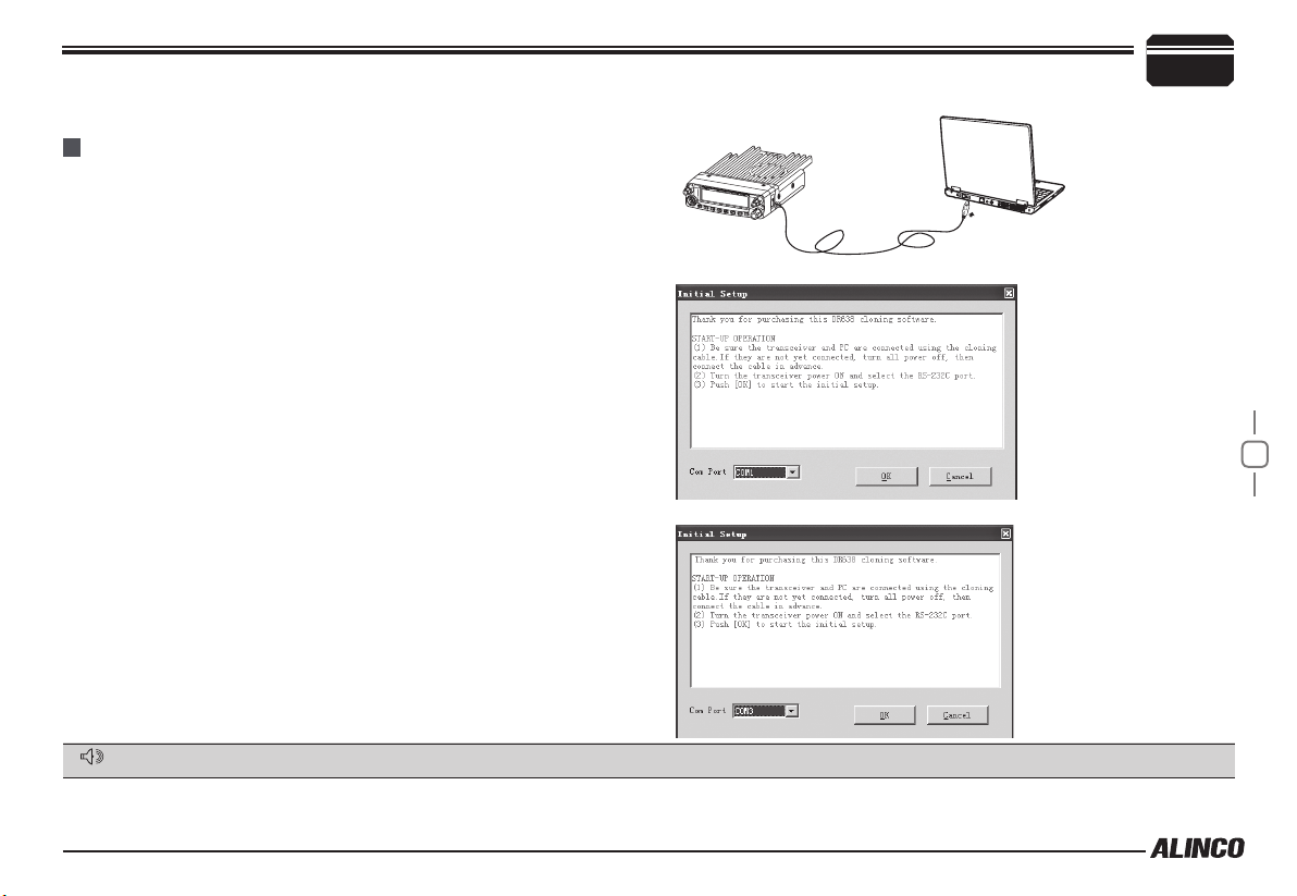
Programming Software Installing and Starting (in windows XP syst1e0m)
9
Double click “DR638 setup.exe”, then follow the installing instruction.
INSTALL USB CABLE DRIVER PROGRAMME
Click st art m enu in compu ter, under “ALL PROGRA MS” menu,
1.
choose and click “USB To Com port” in DR638 program, install “USB
To Com port” driver by indication.
Connect the optional PC50 USB Programming cable to USB port in
2.
PC with transceiver.(As pic 1)
Double click DR638 shortcut or click DR638 in procedure index of
3.
start menu, choose serial com port as indicated then click OK to start
programming software. (As pic 2)
According to instruction, select correct "COM Port"(As pic 3), then
4.
click "OK" to start programming software.
NOTE: Even in same computer, the selective COM Port is different when
USB cable connects with different USB port.
You shall install software before connecting the USB cable line. Switch
on transceiver before writing frequency. You had better not switch on or
off the power supply of transceiver when it is connected with computer,
otherwise, it will make transceiver unable to read or write frequency. In
this case, you have to turn off programming software, pull out USB cable.
then reinsert USB cable and open software, then rechoose COM Port,
it will turn into normal operation. Therefore, please connect transceiver
with computer after switching on the transceiver. Don't restart transceiver
power when it is connected with computer.
This software has product identify system, when rstly installing the software, you have to connect the transceiver,otherwise you can not start the software.
NOTE
Note:This product could program the frequence on computer through interface by manufacturer only.
Pic1
Pic2
32
Pic3
Page 45

10
Maintenance
TROUBLE SHOOTING
Problem Possible Causes and Potential Solutions
(a) Power is on, nothing appears on
Display.
(b) Fuse is blown. Check and solve problem resulting in blown fuse and replace fuse with new fuse.
(c) Display is too dim. Dimmer setting is "LAMP-L". Please make the dimmer setting "LAMP-H".
+ and - polarities of power connection are reversed. Connect red lead to plus terminal and black lead to
minus terminal of DC power supply.
(d) No sound comes from speaker.
Key and Dial do not function. Key-lock function is activated. Cancel Key-lock function.
(e)
33
(f) Rotating Dial will not change
memory channel.
(g) PTT key is pressed but
transmission does not occur.
• Squelch is muted. Decrease squelch level.
• Tone or CTCSS/DCS squelch is active. Turn CTCSS or DCS squelch off.
Transceiver is in CALL mode. Press the VFO or memory mode.
• Microphone connection is poor. Connect microphone properly.
• Antenna connection is poor. Connect antenna properly.
Page 46

General
TX: 136~174MHz
400~480MHz
Frequency Range
Number of Channels 758 channels
Channel Spacing
Phase-locked Step 12.5KHz
Operating Voltage 13.8V DC ±15%
Squelch Carrier/CTCSS/DCS/5Tone/2Tone/DTMF
Frequency Stability ±2.5ppm
Operating Temperature -20~+60
Dimensions(WxHxD) 139(W)x40(H)x212(D)mm
Weight about 1.14kg
RX: 108~180MHz (AM/FM)
220~260MHz (FM)
400~523MHz (FM)
350~399.995MHz (FM)
12.5KHz (Narrow band)
℃
Specifications
Receiver (ETSI EN 300 068)
Narrow band
Sensitivity
(12dB SINAD)
Adjacent Channel
Selectivity
Audio Response +1~-3dB(0.3~2.55KHz)
Hum & Noise ≥40dB
Audio distortion ≤5%
Audio power output
Transmitter (ETSI EN 300 068)
Power Output
Modulation 11KΦF3E
Adjacent Channel
Power
Hum & Noise ≥36dB
Spurious Emission ≥70dB
Audio Response +1~-3dB(0.3~2.55KHz)
Audio Distortion ≤5%
≤0.35μV
≥60dB
2W@10%
>
Narrow band
40W/50W
≥60dB
11
34
Page 47

12
Appendix
51 GROUPS CTCSS TONE FREQUENCY(HZ)
62.5 77.0 91.5 107.2 127.3 151.4 167.9 183.5 199.5 225.7 254.1
67.0 79.7 94.8 110.9 131.8 156.7 171.3 186.2 203.5 229.1
69.3 82.5 97.4 114.8 136.5 159.8 173.8 189.9 206.5 233.6
71.9 85.4 100.0 118.8 141.3 162.2 177.3 192.8 210.7 241.8
74.4 88.5 103.5 123.0 146.2 165.5 179.9 196.6 218.1 250.3
The self dened CTCSS tone supports non standard codes.
pre-programmed
35
The frequency shall be
Self
Dene
1024 GROUPS DCS CODE
000 001 002 003 004 005 006 007
010 011 012 013 014 015 016 017
020 021 022 023 024 025 026 027
030 031 032 033 034 035 036 037
040 041 042 043 044 045 046 047
050 051 052 053 054 055 056 057
060 061 062 063 064 065 066 067
070 071 072 073 074 075 076 077
100 101 102 103 104 105 106 107
110 111 112 113 114 115 116 117
120 121 122 123 124 125 126 127
130 131 132 133 134 135 136 137
140 141 142 143 144 145 146 147
150 151 152 153 154 155 156 157
160 161 162 163 164 165 166 167
170 171 172 173 174 175 176 177
200 201 202 203 204 205 206 207
210 211 212 213 214 215 216 217
220 221 222 223 224 225 226 227
230 231 232 233 234 235 236 237
240 241 242 243 244 245 246 247
250 251 252 253 254 255 256 257
260 261 262 263 264 265 266 267
270 271 272 273 274 275 276 277
300 301 302 303 304 305 306 307
310 311 312 313 314 315 316 317
320 321 322 323 324 325 326 327
330 331 332 333 334 335 336 337
Page 48

340 341 342 343 344 345 346 347
350 351 352 353 354 355 356 357
360 361 362 363 364 365 366 367
370 371 372 373 374 375 376 377
400 401 402 403 404 405 406 407
410 411 412 413 414 415 416 417
420 421 422 423 424 425 426 427
430 431 432 433 434 435 436 437
440 441 442 443 444 445 446 447
450 451 452 453 454 455 456 457
460 461 462 463 464 465 466 467
470 471 472 473 474 475 476 477
500 501 502 503 504 505 506 507
510 511 512 513 514 515 516 517
520 521 522 523 524 525 526 527
530 531 532 533 534 535 536 537
540 541 542 543 544 545 546 547
550 551 552 553 554 555 556 557
560 561 562 563 564 565 566 567
570 571 572 573 574 575 576 577
600 601 602 603 604 605 606 607
610 611 612 613 614 615 616 617
620 621 622 623 624 625 626 627
630 631 632 633 634 635 636 637
640 641 642 643 644 645 646 647
650 651 652 653 654 655 656 657
660 661 662 663 664 665 666 667
670 671 672 673 674 675 676 677
700 701 702 703 704 705 706 707
710 711 712 713 714 715 716 717
Appendix
720 721 722 723 724 725 726 727
730 731 732 733 734 735 736 737
740 741 742 743 744 745 746 747
750 751 752 753 754 755 756 757
760 761 762 763 764 765 766 767
770 771 772 773 774 775 776 777
12
36
Page 49

SAFETYTRAININGINFORMATION
YourAlinco,Incorporated;ElectronicsDivisionradiogeneratorsRFelectromagneticenergyduring
transmitmode.Thisradioisdesignedforandclassifiedas“OccupationalUseOnly”,meaningitmustbeusedonlyduringthe
courseofemploymentbyindividualsawareofthehazards,andthewaysToMinimizeSuchhazards.ThisradioisNOTintended
forusebythe“GeneralPopulation”inanuncontrolledenvironment.ThisradiohasbeentestedandcomplieswiththeFCCRF
Alin
exposurelimitsfor“OccupationalUseOnly”.Inaddition,your
thefollowingStandardsandGuidelineswithregardtoRFenergyandelectromagneticenergylevelsandevaluationofsuch
levelsforexposuretohumans:
to Radio Frequency Electromagnetic Fields.
� American National Standards Institute (C95.1-1992), IEEE Standard for Safety Levels with Respect to Human
Exposure to Radio Frequency Electromagnetic Fields, 3 kHz to 300 GHz.
� American National Standards Institute (C95.3-1992), IEEE Recommended Practice for the Measurement of
Potentially Hazardous Electromagnetic Fields– RF and Microwave.
� The following accessories are authorized for use with this product. Use of accessories other than those (listed in the
instruction) specified may result in RF exposure levels exceed the FCC requirements for wireless RF exposure.
�
FCC OET Bulletin 65 Edition 97-01 Supplement C, Evaluating Compliance with FCC Guidelines for Human Exposure
co,Incorporated;ElectronicsDivision
radiocomplieswith
To ensure you’re your expose to RF electromagnetic energy is within the FCC allowable limits for occupational use, always
adheretothefollowingguidelines
T
heinformationlistedaboveprovidestheuserwiththeinformationneededtomakehimorherawareofRFexposure,
andwhattodotoas‐surethatthisradiooperateswiththeFCCRFexposurelimitsofthisradio.
ElectromagneticInterference/Compatibility
Duringtransmissions,Alinco,Incorporated;ElectronicsDivisionradiogeneratesRFenergythatcanpossiblycauseinterference
withotherdevicesorsystems.Toavoidsuchinterference,turnofftheradioinareaswheresignsarepostedtodoso.DONOT
operatethetransmitterinareasthataresensitivetoelectromagneticradiationsuchashospitals,aircraft,andblastingsites.
Occupational/ControlledUse
Theradiotransmitterisusedinsituationsinwhichpersonsareexposedasconsequenceoftheiremploymentprovided
thosepersonsarefullyawareofthepotentialforexposureandcanexercisecontrolovertheirexposure.
1
InordertocomplywithRFexposurerequirements,aminimumdistanceof mustbemaintainedbetweentheantenna
00cm
andallpersons
Page 50

ThisdevicecomplieswithIndustryCanadalicence‐exemptRSSstandard(s).Operationissubject
tothefollowingtwoconditions:
(1)thisdevicemaynotcauseinterference,and
(2)thisdevice mustacceptanyinterference,includinginterferencethatmaycauseundesired
operationofthedevice.
Le présent appareil est conforme aux CNR d'Industrie Canada applicablesaux appareils radio
exemptsdelicence.L'exploitationestautoriséeauxdeuxconditionssuivantes:
(1)l'appareilnedoitpasproduiredebrouillage,et
(2) l'utilisateur de l'appareil doit accepter tout brouillage radioélectrique subi, même si le
brouillageestsusceptibled'encompromettrelefonctionnement.
 Loading...