

Page 1
Parameter Setting Mode
(Refer page 27 for how to enter the setting mode.)
Time-Out-Timer
The TOT feature is popular in repeater systems. It prohibits the users from transmitting on the
repeater after a certain period of time has elapsed. By setting this function and activating it according to the repeaters’ requirement, the radio alerts the user by a beep 5 seconds prior to time-out.
When the time is expired, transmitting stops and the transceiver automatically returns to recei ving
mode. This a v oids the repeater going into its TO T mode. Until the PTT is released once and pressed
again, the transceiver will not transmit.
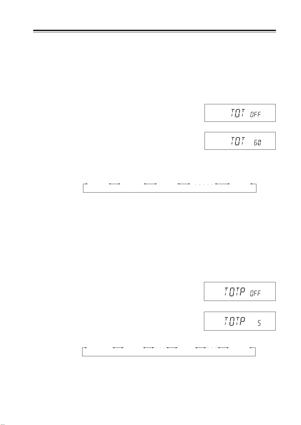
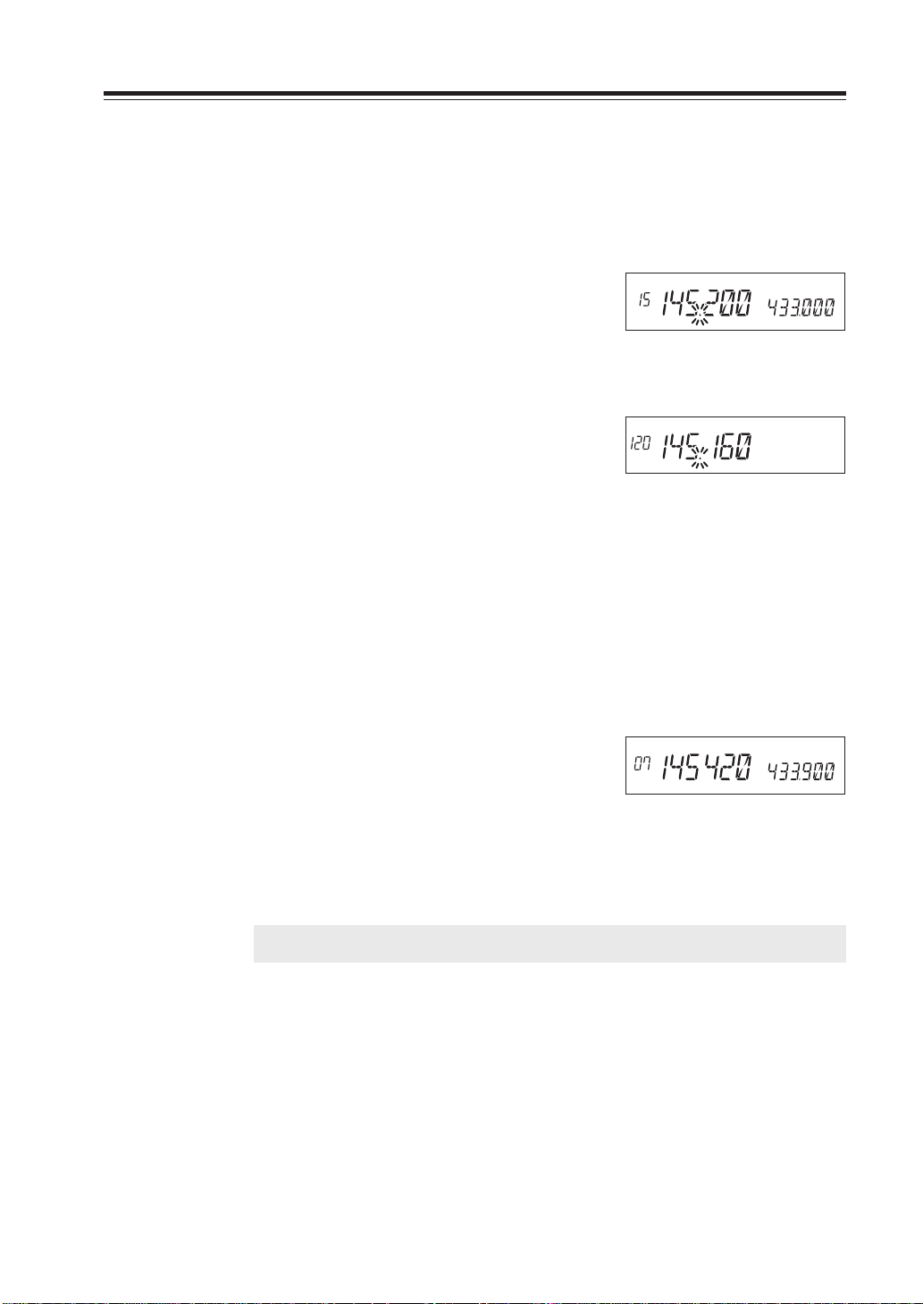
1. In this Menu the default display shows TOT-
OFF.
2. Rotate the main dial to select time-out time.
The display should change as shown. The number followed by TOT is the time-out time in
seconds.
The TOT feature is selectable up to 450 seconds (7.5 minutes).
TOT OFF TOT 30 TOT 60 TOT 450
During the setting time of 60 seconds
TOT Penalty
When transmission is shut down in the TOT mode, this function prohibits another
transmission during a selected TOT penalty period regardless of the PTT key pressed.
A beep sounds when the PTT key is pressed during the TOT penalty period. If the PTT
is continuously pressed over both TOT and the TOT penalty period, this function will be
automatically cancelled.
Setting the TOT penalty time
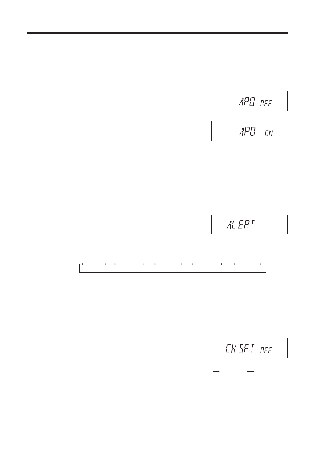
1. [TOTP OFF] icon appears on the display.
2. By rotating the main dial, the display changes
as below and TOT penalty setting is changed.
The penalty time can be set up to 15 seconds.
In case the setting time is 5 seconds
TOTP 0FF TOTP 1 TOTP 4 TOTP 15
29
Page 2
Parameter Setting Mode
CKSFT OFF CKSFT ON
(Refer page 27 for how to enter the setting mode.)
APO-Auto Power OFF
This feature will automatically shut off the transceiver. It is useful for mobile operation to avoid
draining the car battery . If there is no activity or use of the radio, it will turn off automatically after
30 minutes followed by a beep sound.
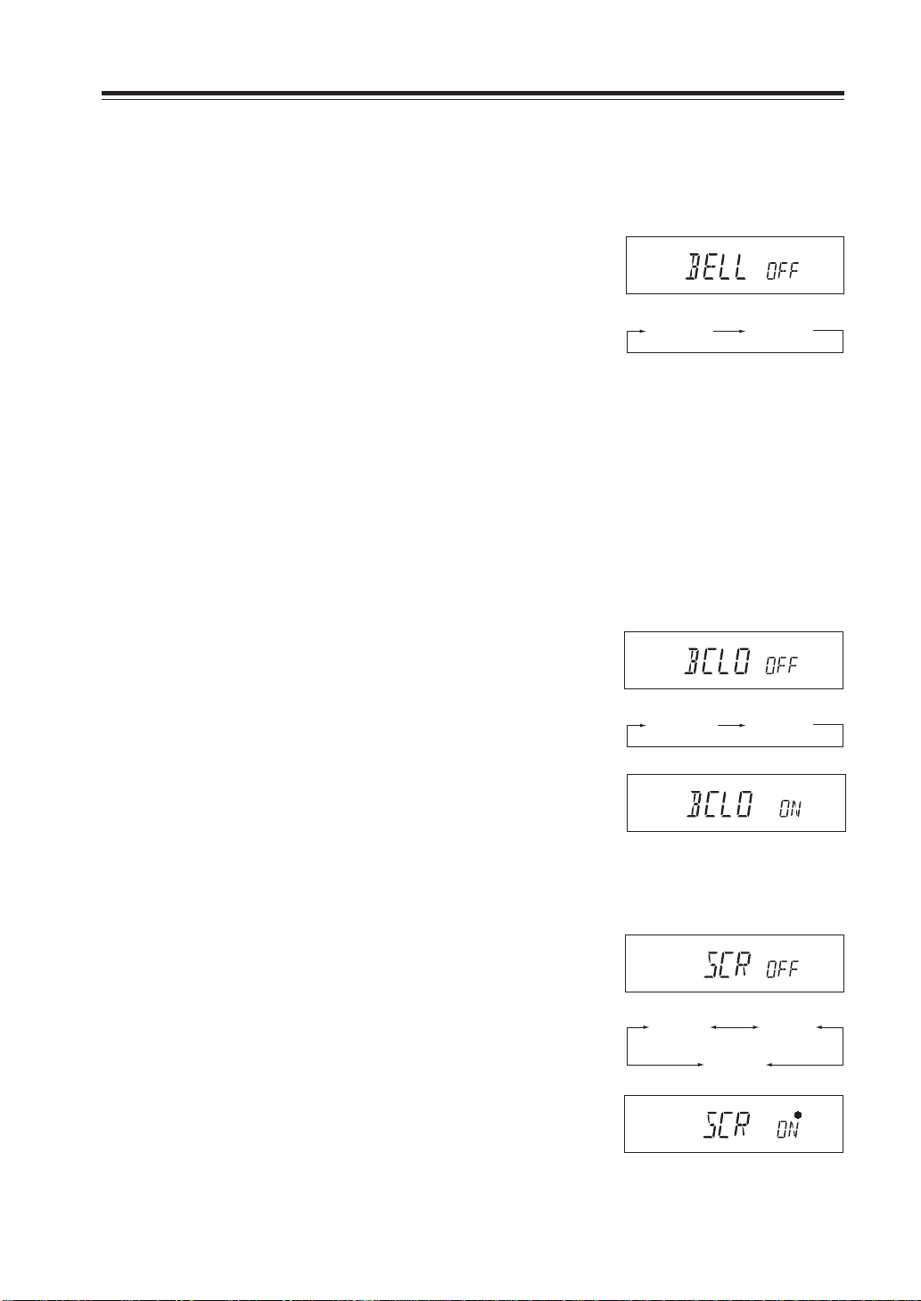
1. Default is APO-OFF.
2. Rotate dial to select APO-ON to activate the
function.
During the ON setting
Tone-Burst Frequency
This is to access Tone-Burst repeaters which require a certain pitch of audible tone to activate
“sleeping” repeaters. Usually, a repeater system does not require the tone once the repeater is
activated.
Tone Burst frequency can be set to ALERT, 1750Hz, 2100Hz, 1000Hz and 1450Hz.
(ALERT is an intermittent recalling sound)
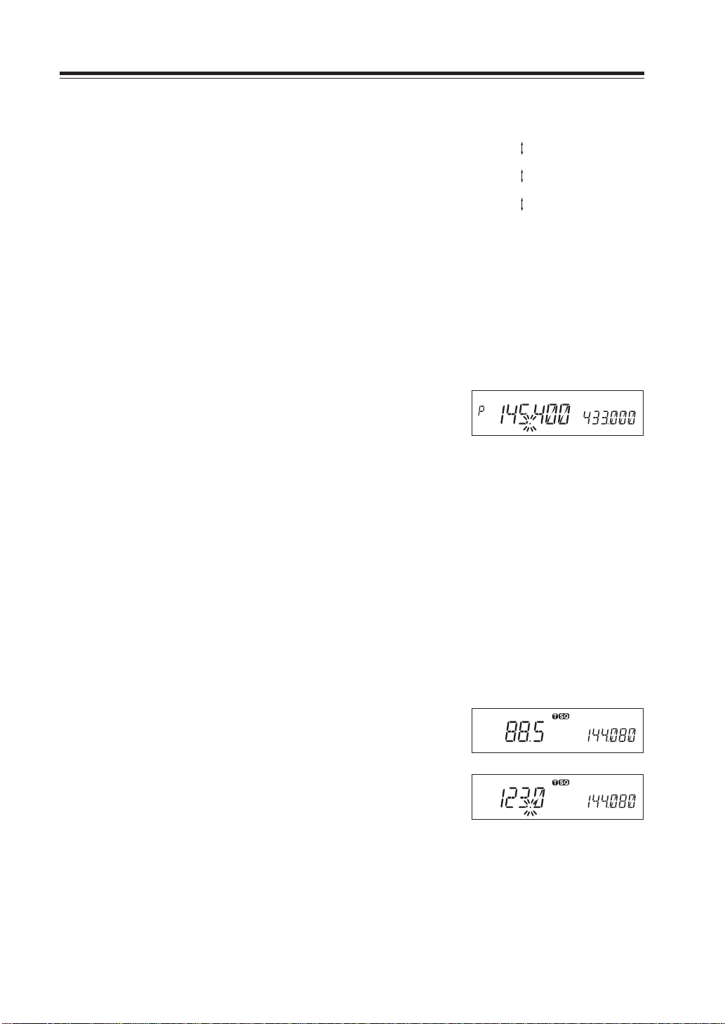
1. [ALERT] icon appears on the display.
2. By rotating the main dial, the display changes
as below and Tone Burst frequency setting is
changed.
ALERT TB 1750
TB 2100
TB 1000 TB 1450
Clock shift
In the unlikely event that CPU clock noise is present on a particular operating frequency programmed into the radio, you can shift the CPU clock frequency to avoid the CPU clock noise,
which normally is so weak that it is inaudible even if the radio is tuned exactly to its frequency.
1. [CKSFT OFF] icon appears on the display.
2. By rotating the main dial, the display changes
as shown and Clock shift setting is changed.
30
Page 3
Parameter Setting Mode
BELL OFF BELL ON
(Refer page 27 for how to enter the setting mode.)
Bell
The bell informs you that you are being called by sounding a bell, and flashing the bell icon on the
display.
1. [BELL OFF] icon appears on the display.
2. By rotating the main dial, the display changes
as shown and Bell function setting is changed.
Busy-Channel-Lock-Out (BCLO)
This function prohibits transmission as long as there is a signal on the receiving frequency.
The default is BCLO-OFF, which is the of f position. By acti v ating this function, the radio transmits
only when:
1.No signal is received (BUSY icon is gone) on the receiving frequency.
2.Tone-squelch is opened by the corresponding CTCSS tone of the receiving signal.
3.As above, with DCS code.
Otherwise a beep sounds but the unit does not transmit even when the PTT is pressed.
1. [BCLO OFF] icon appears on the display.
2. By rotating the main dial, the display changes
as shown and BCLO setting is changed.
Theft Alarm
(Please refer page 44 for details)
1. [SCR OFF] icon appears on the display.
2. By rotating the main dial, the display changes
as shown and Theft Alarm is set ON/OFF.
3. When Theft Alarm is set, [*] icon appears on
the display.
BCLO OFF BCLO ON
SCR OFF SCR ON
SCR DLY
31
Page 4
Parameter Setting Mode
Illumination color setting
This is to select display illumination color.
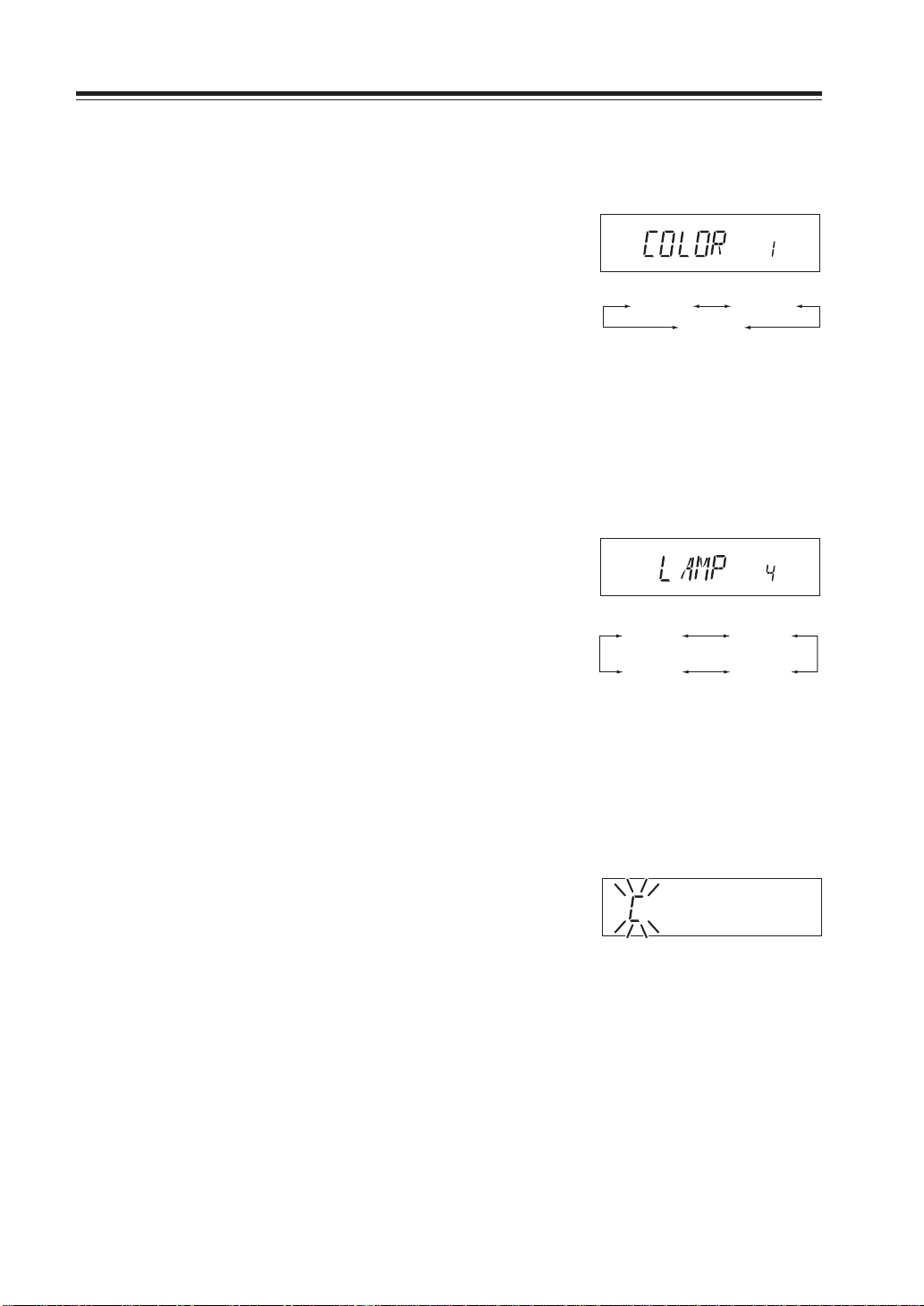
1. [COLOR 1] icon appears on the display.
(Refer page 27 for how to enter the setting mode.)
2. By rotating the main dial, the display changes
as right and illumination color is changed.
COLOR 1 is Amber (Red) illumination.
COLOR 2 is Yellow illumination.
COLOR 3 is Orange illumination.
COLOR 1 COLOR 2
COLOR 3
Dimmer
This is to provide better visibility of the display by dimming the display illumination in the dark.
1. [LAMP 4] icon appears on the display.
2. By rotating the main dial, the display changes
as below and Dimmer setting is changed.
It is bright with LAMP 4 and will be darker
with 3-2-1.
LAMP 1 LAMP 2
LAMP 4 LAMP 3
Call sign setting (In packet operation)
This is to register the call sign of your station to transmit in Packet communication mode. 36
characters, A - Z and 0 - 9 are available for registration.
32
1. The display shows [C] flashing.
2. Rotate the dial to select a character to be pro-
grammed.
3. By pressing the BAND key, the character is il-
luminated and entered.
An identical character to the one just entered
flashes on the immediate right ready to be entered.
4. Enter with the BAND key (Repeat the same
sequence). You can program up to 6 digits.
5. Pressing the CALL key during programming
will delete all characters to be programmed.
Page 5
Transmission speed setting
(In packet operation)
This is to set transmission speed at the time of data communication.
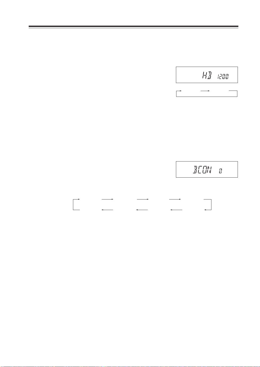
1. [HB 1200] icon appears on the display.
Parameter Setting Mode
(Refer page 27 for how to enter the setting mode.)
2. By rotating the main dial, the display changes
as right and setting is changed.
HB 1200 HB 9600
[HB 1200] Transmission speed is set at 1200bps.
[HB 9600] Transmission speed is set at 9600bps.
Beacon interval setting
(In geolocating communication/A.P.R.S.®)
This is to set a transmission time separation of GPS location data when Geolocating communication is in operation.
1. [BCON 0] icon appears on the display. No
transmission is made at BCON 0.
2. By rotating the main dial, the display changes
as below and setting is changed.
BCON 05
(30sec.)
BCON 0
(OFF)
Setting for call sign, transmission speed and beacon interval will be transmitted to TNC unit (EJ50U) by TNC clone.
Operation of TNC will stay unchanged until TNC clone transmission will be completed.
BCON 1
(1min.)
BCON 30
(30min.)
BCON 3
(3min.)
BCON 20
(20min.)
BCON 5
(5min.)
BCON 10
(10min.)
33
Page 6
Useful functions
Reception band switching
This is to switch the receiving band. On VHF side, FM broadcasting can be received.
1. After pressing the FUNC key, press the CALL
key while [F] icon is on.
On VHF side, the band s witches from 144MHz
band to FM broadcasting band.
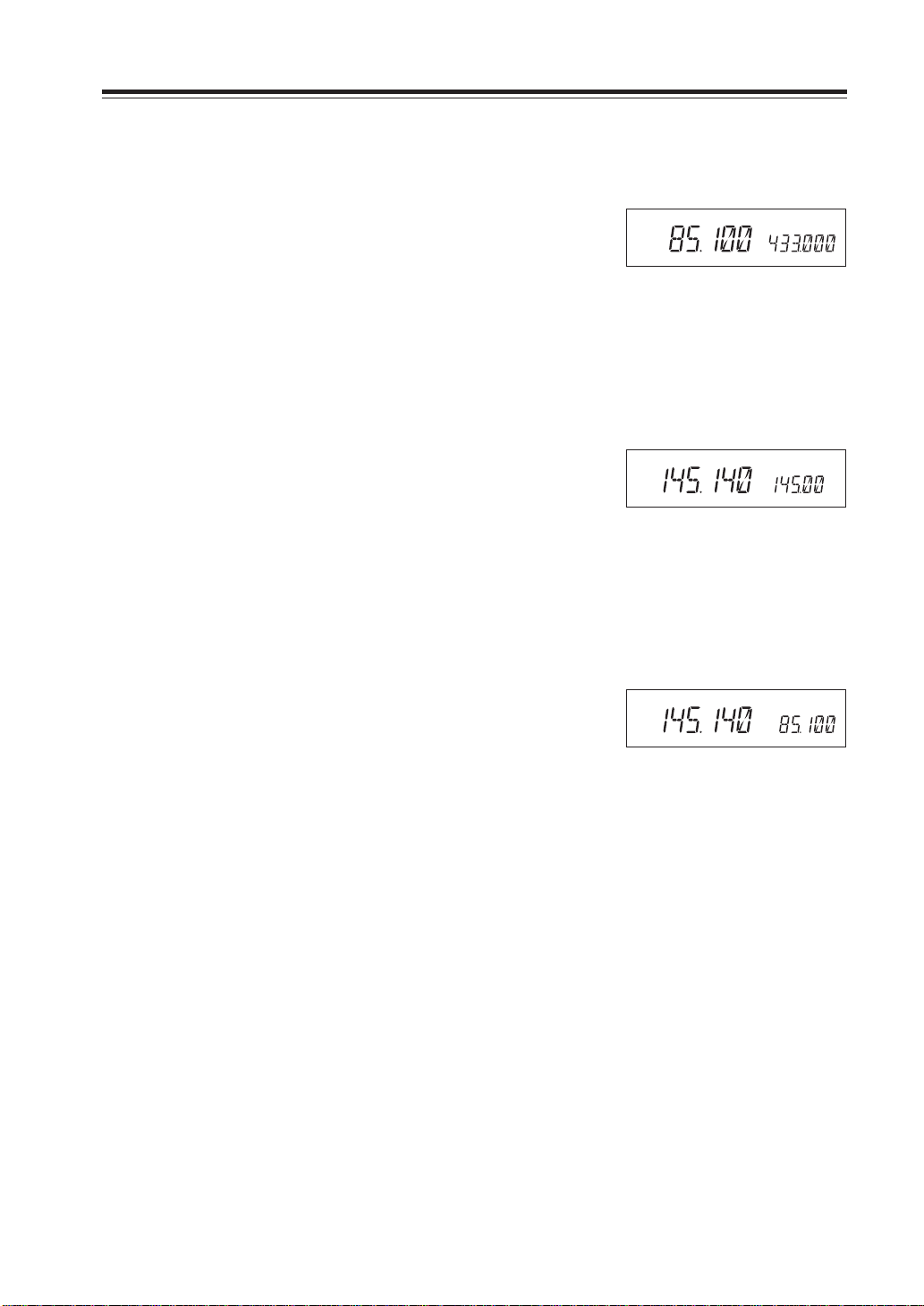
V-V/U-U simultaneous reception
This is to receive the same frequency band simultaneously both on the MAIN band and the SUB
band, while in the VFO mode.
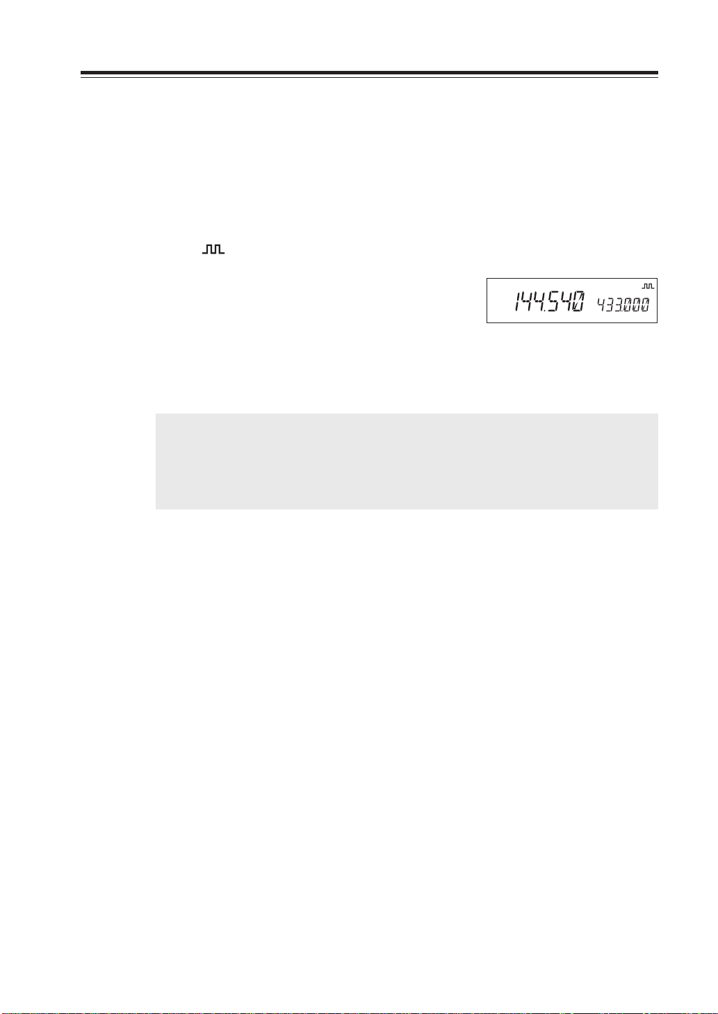
1. After pressing the FUNC key, press the BAND
key while [F] icon is on.
Display on the SUB band changes to the same
frequency band as the MAIN band.
The default frequency of the SUB band is VFO
default frequency.
When V-V/U-U is set
2. To change frequency or setting of the SUB
band, switch the SUB band to the MAIN by
the BAND key before operation.
3. By pressing the BAND key after pressing the
FUNC key again, the display will return to the
normal V-U display.
If you switch BAND while having FM broadcasting band on the MAIN side, the display will
show [SUB] icon illuminating.
At this time, the MAIN band will be exclusive
for reception and not be ready for transmission.
When [SUB] icon is on the display, memory
programming is not possible either.
SUB
In this case no transmission is possible
on the MAIN band
34
Page 7
Single-band mode
This is to use the unit just like a single-band transceiver onl y for VHF or UHF, b y erasing displa y on
the SUB side.
1. Press the BAND key while pressing and hold-
ing the FUNC key.
The display on the SUB side disappears and its
function is temporary suspended.
While in the V-V/U-U mode, the unit will not
enter to the single-band mode.
VFO Auto-program setting function
This is to program various automatic settings in a certain frequency range in the VFO mode.
It is useful for quick repeater access.
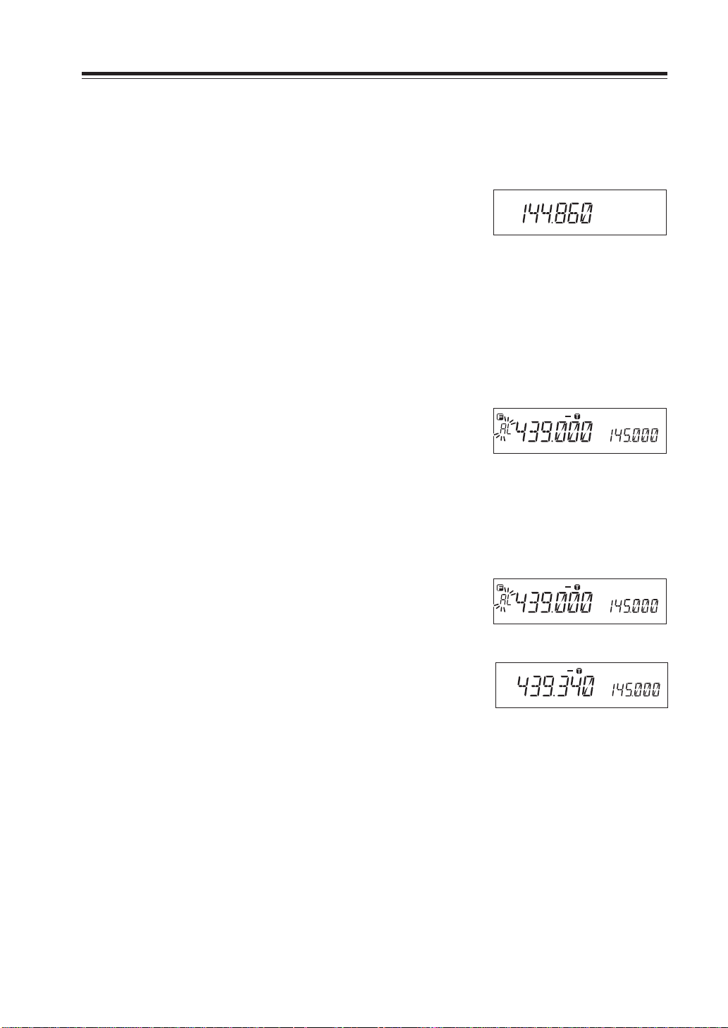
1. Program the lower edge frequency of the de-
sired range as well as other parameters such as
repeater shift, CTCSS tone into the [AL] channel in the memory mode (Refer page 19).
Programmable items are frequency, shift direction, offset frequency, tone ENC frequency and
its setting, tone DEC frequency and its setting,
DCSEN code and its setting, and DESDEC setting.
When 439.000MHz 88.5Hz ENC-5.000MHZ
shift is set in AL
Useful functions
2. As above program the higher edge frequency
in the [AH] channel of the memory. Disregard
other settings such as CTCSS tones or repeater
shift.
3. In the VFO mode, what have been programmed
in the AL memory are automatically set within
the frequency band between AL and AH.
Temporary setting change is possible between
AL and AH, but once frequenc y is changed by
rotating the dial, all the preset values in AL will
be restored.
Shows an example within
VFO auto-program setting
35
Page 8
Us eful functions
SCANNING FUNCTION
Use this function to automatically search for signals. 6 different scan types are available in the unit.
In parameter setting mode, choose Timer mode or Busy mode to determine the desired resuming
condition. If the CTCSS(TSQ) squelch or DCS squelch is set, the audio can be heard only when the
tone/code matches the incoming signal. Otherwise, scanning stops but no audio will be heard. The
direction of scan, upward or downward, can be changed during the scan b y rotating the main dial or
pressing UP or DOWN keys in the desired direction.
•VFO Scan
Scans all VFO channels in regard to the preset tuning step.
1. Enter VFO mode.
2. Press UP (to go upward) or Down (to go down-
ward) key for more than 1 second but less than
2 seconds.
3. The scan starts. It stops at the frequency where
the incoming signal is detected, and resumes
the scan according to the resume setting.
4. Press any key (other than UP/DOWN keys) to
exit.
NOTE: • By pressing the UP/DOWN key for more than 2 seconds the frequency changes as long as key
is pressed.
• When both MAIN and SUB bands are in the VFO mode (except when in V-V/U-U), you can
operate the BAND key even during scanning and simultaneous scanning both for V and U is
possible.
36
Page 9
•Memory Scan
Scans all memory channels unless Memory skip feature is
selected for a given memory.
1. Enter Memory mode.
2. Sequence is the same as in VFO scan. Use UP/
DOWN keys for commands.
Range of Memory Scan
Exclusive scanning for VHF/UHF:
If scanning is started somewhere between 00 and 79,
scanning is always repeated within this range.
Mixed scanning for V/U:
If scanning is started somewhere between 100 and 139,
scanning is always repeated within this range.
Useful functions
During mixed scanning for V/U
•Skip-channel setting
A memory channel set as a skip-channel will be excluded
from scanning during Memory Scan, and can be set even after the memory is programed.
1. Press the FUNC key in the Memory mode, and
then press the V/M key while [F] icon is illuminating. Skip setting of a memory channel
selected is made.
A memory channel with skip setting will have
1MHz decimal point put off.
2.
To cancel skip-channel setting, repeat the step 1.
IMPORTANT: CALL, PL, PH, AL, AH and ch.99 are always skipped.
37
Page 10
Useful functions
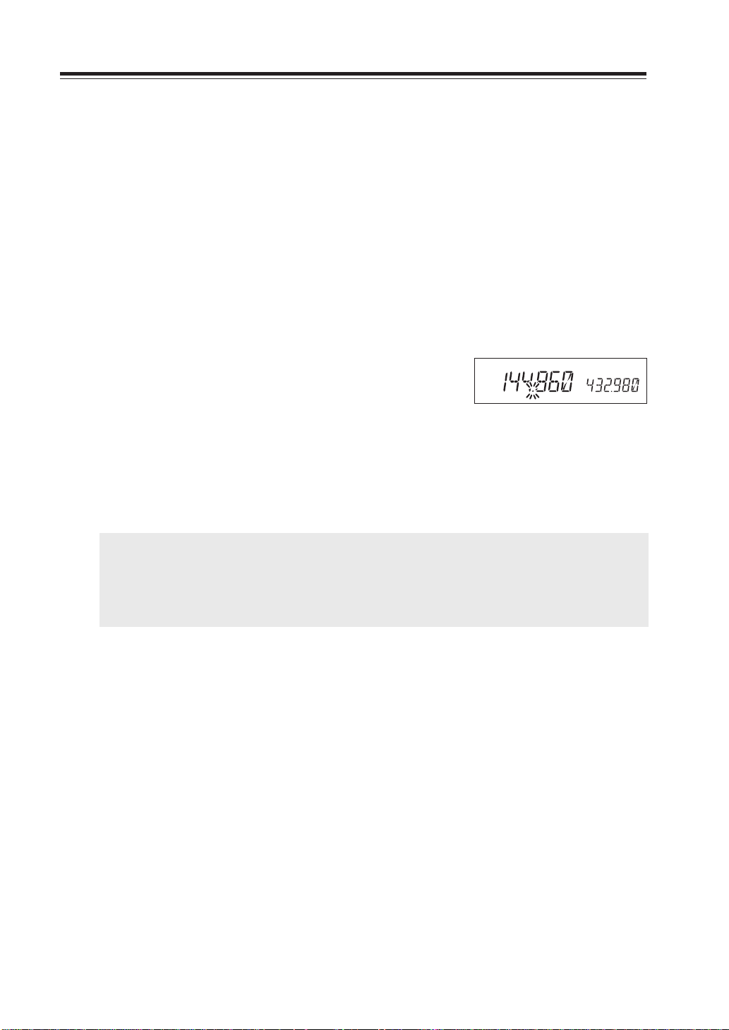
•Program Scan
This is a type of VFO scan, but b y setting the frequenc y range
of the VFO into PH and PL channels, it only scans between
those frequencies. W ith setting the PH and PL properly , up to
3 Program scan ranges will be av ailable, w hich are L-PH, PLPH and PH-H.
1. Enter the VFO mode and set the PL and PH
frequency into the designated memory channels. Refer to Memory setting for the proper
sequence.
2. Return to VFO mode by pressing V/M key. Set
the VFO to the frequency within the range to
be program-scanned.
3. Press MHz key for more than 1 second to start
scanning. During this scan mode, a decimal
point flashes as shown.
4. Use main dial or UP/DOWN keys to change
the direction. Press any key (other than the UP/
DOWN keys) to exit.
Band edge H
PH
PL
Band edge L
Program Scan is going
•Tone Scan
This function automatically searches for the CTCSS tone an
incoming signal might carry. This feature is useful to search
the encoding tone of a repeater, or to communicate with a
station operating in TSQ (CTCSS squelch) mode.
1. Press TS/DCS key to enter CTCSS decode set-
ting mode.
2. Press UP/DOWN key for more than 1 second
but less than 2 seconds to start scanning. It scans
38 tones in order.
3. The decimal point on the tone frequency will
flash, and it stops when the matching tone is
detected.
4. The scan won’t resume until the operation is
repeated.
5. Press any key (other than UP/DOWN keys) to
exit.
38
Page 11

•DCS scan
Same as previous, but for DCS code search.
1. While in the DCS setting, press the UP/DOWN
key for more than 1 second but less than 2 seconds to start scanning.
(It scans 105 DCS codes in order.)
• During scanning, 1 MHz order decimal point
will flash.
• The scan stops when the matching DCS code
is detected and reception starts.
IMPORTANT: After scanning is over, it will not resume until another dialing or UP/
DOWN key pressing will be made.
2. After scanning is over, pressing any key other
than UP/DOWN key will cancel the scan mode.
KEY-LOCK FUNCTION
Useful functions
DCS
This will lock the keys to avoid unintentional changes.
1. Press FUNC key and press TS/DCS key while
F icon is on the display.
2. The [ ] icon appears.
3. With this function activated, only the follow-
ing commands can be accessed:
• PTT
• FUNC+TS/DCS to cancel this function
• Monitor function (to release squelch for weak
signal reception)
• Squelch setting
• UP/DOWN keys
TONE BURST
This feature is to recall the other party by adding a tone to the transmitting signal.
• While the PTT key and the DOWN key are pressed together, a tone signal is transmitted.
• The default is an alert sound. Transmitted tone can be changed in the Setting mode.
• For DR-620E, 1750Hz tone burst signal is transmitted as the default setting, so that a repeater
can be accessed to.
39
Page 12

Useful functions
Narrow-band mode
This feature is to prepare for the possible future change of the tuning step.
1. Press the MHz key together with the FUNC key.
[Nar] icon illuminates on the display to show
the unit is in the Narrow mode.
2. Repeat the same operation to return to the nor-
mal mode.
IMPORTANT: In the NARROW mode, the microphone gain and modulation during trans-
AM receiver mode
This mode is to receive AM signals.
1. Press the TS/DCS key while the FUNC key is
pressed.
[AM] icon illuminates on the display to show
the unit is in the AM reception mode.
2. Repeat the same operation to return to the FM
mode.
Even while AM mode is set, the FM mode will
resume for TX even though AM icon remains.
Nar
In the Narrow mode
mission and the demodulation range during reception will be lower.
AM
40
Page 13

Selective Communication
Many repeaters require a CTCSS tone or a DCS code encode setting as a “key” to access the
system, so-called “selective-calling”. Sometimes, CTCSS or DCS decode features are used on the
output of a repeater so they can be used as a squelch. In this mode, regardless of the main squelch
status, the audio can be heard ONLY when the matching tone/code signal is received. The combination of CTCSS squelch and DCS function is not available; only one or the other may be used for
a given frequency.
Tone-squelch (CTCSS) and DCS
1. Press TS/DCS key. The current setting will be
displayed with T/SQ/DCS icons and relative
frequency/code. Press the same key to select
T/SQ/DCS setting.
T
88.5
T/SQ
88.5
The original status
DCS
023
2. The numbers (such as 88.5) represent the
CTCSS frequency in Hz. When it is displayed
with the T icon only, the unit transmits the subaudible tone while the PTT is pressed (encode)
and the repeater access is enabled (assuming
the repeater is using 88.5).
3. Press the same key again so that the SQ icon
shows up on the display. This is the CTCSS
decode frequency. This enables CTCSS squelch
(or Tone Squelch, TSQ).
4. Press it again so that the 3-digit number and
DCS icon is displayed. This is the DCS code,
and it enables DCS encoding and decoding.
For 2-4, rotate the main dial or press the UP/DOWN keys to change tone or code. Press any key
(Except TS/DCS, UP/DOWN keys) to enter the setting and return to original status. The T/SQ/DCS
icon will remain on the display to sho w the current status. T o exit, simply use the TS/DCS key and
press it until the relative status icon T/TQ/DCS disappears.
The CTCSS encoding and decoding frequencies may be set differently. The encode setting frequency automatically relates to the decode setting, but decode setting does not affect encode. The
standard set of 38 different CTCSS tones are available as shown on the chart below. DCS encode/
decode cannot be separated and are selectable from 104 codes as shown below and following page.
67.0 71.9 74.4 77.0 79.7 82.5 85.4 88.5
91.5 94.8 97.4 100.0 103.5 107.2 110.9 114.8
118.8 123.0 127.3 131.8 136.5 141.3 146.2 151.4
156.7 162.2 167.9 173.8 179.9 186.2 192.8 203.5
210.7 218.1 225.7 233.6 241.8 250.3
41
Page 14

Selective Communication
023 025 026 031 032 036 043 047 051 053 054 065
071 072 073 074 114 115 116 122 125 131 132 134
143 145 152 155 156 162 165 172 174 205 212 223
225 226 243 244 245 246 251 252 255 261 263 265
266 271 274 306 311 315 325 331 332 343 346 351
356 364 365 371 411 412 413 423 431 432 445 446
452 454 455 462 464 465 466 503 506 516 523 526
532 546 565 606 612 624 627 631 632 645 654 662
664 703 712 723 731 732 734 743 754
DET setting
In case DET mode in DCS operation is preferred, press H/L key w hile DCS code is displayed in the
setting mode. Observe that a decimal point appears then follow the remaining sequence to set the
parameter and exit.
DET on DCS function stands for Detect-Only mode. In DCS operation, the TX signal carries
digital code such as 001010000 determined by setting the 3-digit code such as 123,124 etc. This
stream is modulated with very low sub-audib le frequenc y. The RX side, just like TSQ, detects this
stream and determines the squelch operation. This DCS code stream is transmitted all the way
through the communication like CTCSS tone (in this case a single continuous tone, instead of
digital coded stream).
It is necessary for receiver to correctly and CONTINUOUSLY receive this DCS digital stream to
hold the squelch open, otherwise the CPU thinks that the signal is unwanted and it closes the
squelch. But due to noise or weak signal strength etc, sometimes it is difficult to continuously
receive DCS stream. By activating DET, the receiver opens squelch when the first corresponding
DCS stream is received, then thereafter, regardless of the status of DCS codes the DCS squelch
remain opened.
Advantage of DET
It enables DCS squelch operation even in poorer condition, opening the squelch only when
corresponding DCS coded signal is received.
Disadvantage of DET
When it is activated, and suppose 2 stations are sharing the same channel with using DCS
selective-calling technique and transmitting at the same time, after the station A with corresponding DCS is gone, you may still hear the station B although he can't open your DCS
squelch by his signal alone.
42
Page 15
Digital voice communication (DR-620T only)
By installing an optional digital unit EJ-47U, digital voice
communication becomes enabled.
1. Install EJ-47U to the connecter CN3 of the unit.
2. Press the FUNC key, and then press the SQL
key while [F] icon is illuminating.
[ ] is shown on the display.
3. Press the FUNC key or the PTT key to enter
the digital communication mode. Repeat step
2 to exit and return to analog FM mode.
4. To cancel the digital communication mode,
press the SQL key while the display shows
codes in step 2.
IMPORTANT: During setting, code is displayed and switched by rotating the dial, but it does
not affect the function of EJ-47U. Please disregard this setting sequence. The
digital voice operation within the amateur radio frequency may be prohibited,
restricted or subject to special station license. Please be sure to consult with
your local authority prior to operate this mode.
Selective Communication
When digital setting is made
43
Page 16

Special Functions
THEFT ALARM
This alert uses a beep sound when the unit is about to be removed in an improper manner. This
function is useful when the unit is installed in a vehicle.
To connect, set and operate
IMPORTANT: Be sure to connect the power cable directly to a car battery. The power cable of this
unit requires voltage at all times to activate this function.
For the same reason, ACC ON/OFF feature must be deactivated.
DC power cable
Handle of the car etc.
Transceiver
1. Wire the alarm cable (There are 2 ways to con-
figure).
1. Modifying and inserting 3.5 Ø stereo plug
for alarm into the SP terminal jack in the
back, as the figure shows.
This configuration is recommended for vehicle installation for the easier removal of
the cable
2. Modifying and inserting the provided wiring cable UX1290A into the connecter
CN10 in the unit.
This configuration is recommended for
semi-permanent setting. By selecting this
configuration speaker remains active, either
internal or external, as configured.
Ensure the tube of the
cable goes through the
slot on the chassis.
Battery
3.5 Ø stereo plug: Looped
UX1290A: Extended and looped
Connect and loop the red and black lead.
44
2. Be sure to fix the alarm cable to a steering
etc. as the figure shows.
Black Red
CN10
Page 17

Special Functions
N
T
VHF/UHF TWINBAND FM TRANSCEVER
3. Set SCR-ON in the setting mode. The [
] icon
*
will appear on the display.
4. Turn OFF the unit.
Alarm function is activated , the displa y will turn
off and TX display lamp will start illuminating.
TX display lamp
MW
V/M
MAIN
TX/RX
MAIN
VOL
VV/UU
BAND
VHF/UHF TWINBAND FM TRANSCEVER
RX BAND SHIFT LOCK
CALL MHz
TS/DCS
PACKET DIGITAL
H/L SQL FU
DR-620
5. To deactivate, turn ON the unit and set SCR-
OFF in the setting mode.
IMPORTANT: • To activate the function, be sure to switch OFF the power after having con-
nected the cable for alarm. (Connecting it after the power is off may activate
the alarm)
• The alarm will not be active unless the PWR switch is turned off.
• The alarm function will not operate if the power is OFF in the ACC power sup-
ply control function.
• The alarm cable A/B provided with DR-135/435 are not compatible with this
unit.
SE
How the alarm operates
When the alarm cable is removed from the port or cut without using the proper sequence, the alarm
sounds for 10 minutes. During the alarm, the unit goes to receive on memory channel 99, according to its pre-programmed setting (TSQ/DCS accepted).
To cancel alarm setting while the alarm is in work
1. When a signal is received on ch.99 the alarm stops. If ch.99 is empty the unit stays
monitoring the Main-VFO frequency. Turning on the unit with SQL key pressed
also cancels the alarm.
2. When the power is OFF again, the alarm setting will resume.
NOTE: The alarm feature on DR-620TA version functions in a slightly different manner.
1. When the alarm starts, the unit alternates between transmit and receive on ch.99 every 5
seconds for 5 minutes.
2. Setting and operation of the function are the same as other versions.
This feature allows you to monitor and to control the alarm from a remote place by using
ch.99 on memory mode.
45
Page 18

Special Functions
N
T
VHF/UHF TWINBAND FM TRANSCEVER
Setting alarm starting time
Choose this operation when a delay period is desired.
1. Enter the Parameter setting mode as described
previously and select SCR-DLY. Follow the
previous instruction to set.
2. Turn off the unit. Display will disappear but
TX display lamp
MW
V/M
MAIN
TX/RX
MAIN
VOL
VV/UU
RX BAND SHIFT LOCK
BAND
CALL MHz
the LCD illumination stays on. After 20 seconds TX LED lights up, illumination dims, and
alarm functions. The system won’t work during the 20 second “DELAY” period.
3. The alarm sounds under the same condition as
described previously. There is a 20 second delay until the alarm sounds. During the 20 second period, only the display illumination is lit.
Turn ON the unit with the SQL key pressed
during “DELAY” period to cancel the alarm
function.
IMPORTANT: Please set the parameters at SCR-OFF during normal operation.
NOTE: Please use a sticker provided indicating installation of the theft alarm device.
VHF/UHF TWINBAND FM TRANSCEVER
PACKET DIGITAL
TS/DCS
H/L SQL FU
DR-620
SE
46
Page 19

Cable Clone
This feature will copy the programmed data and parameters in the master unit to slave units.
3.5 ø stereo-mini plug
Master side Slave side
Plug configuration (both for Master/Slave)
GND
Connection
Make a cable using 3.5 mm stereo-mini plugs as shown above. Make a master unit by setting and
programming it as desired. Turn off both units. Connect the cable between the DATA jacks on both
master and slave. Turn both radios on after the connection is made.
Special Functions
DATA
TX/RX
IMPORTANT: Be sure to connect cables while the unit is turned OFF.
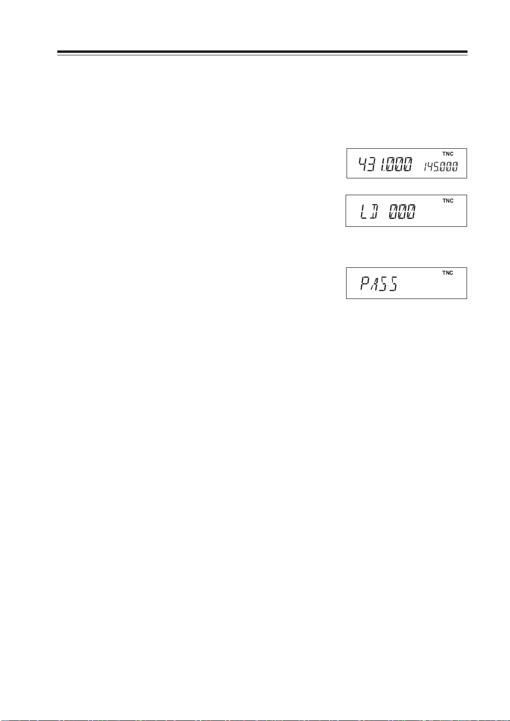
Setting on the Slave side
1. Go to receive mode (VFO or Memory). Avoid
using 9600 bps data reception.
2. When it receives the clone data, LD*** shows
up on the display.
3. When the transmission is successfully finished,
the display will show [PASS].
4. Turn off the power. Disconnect the cable and
repeat the sequence to clone the next slave unit.
47
Page 20

Special Functions
Setting on the Master side
1. Press CALL key with FUNK key pressed.
CLONE will be displayed and the radio enters
the clone mode.
2. Press PTT. SD*** will be displayed and it starts
sending the data into the slave unit.
3. [PASS] will appear on the display when the data
is successfully transmitted.
During transmission
4. The master radio may stay turned on for the
next clone. Turn off the unit to exit from the
clone mode.
If the data is not successfully transmitted, turn off both units, make sure the cable connection is
correct and repeat the entire operation from the beginning.
IMPORTANT: Never pull off the cable while the data is transmitted in clone mode.
When transmission is finished
48
Page 21

Packet Communication
Packet communication is a high-speed data communication system transmitting a package of data
by keyboard operation of a personal computer. The use of Digi-peaters (relay stations) offers communications with DX stations (distant stations). For packet communication, a personal computer
and an optional EJ-50U (TNC unit) are required other than this unit.
EJ-50U is equipped with Digi-peater function. For detailed operation, please refer to the instruction manual of EJ-50U.
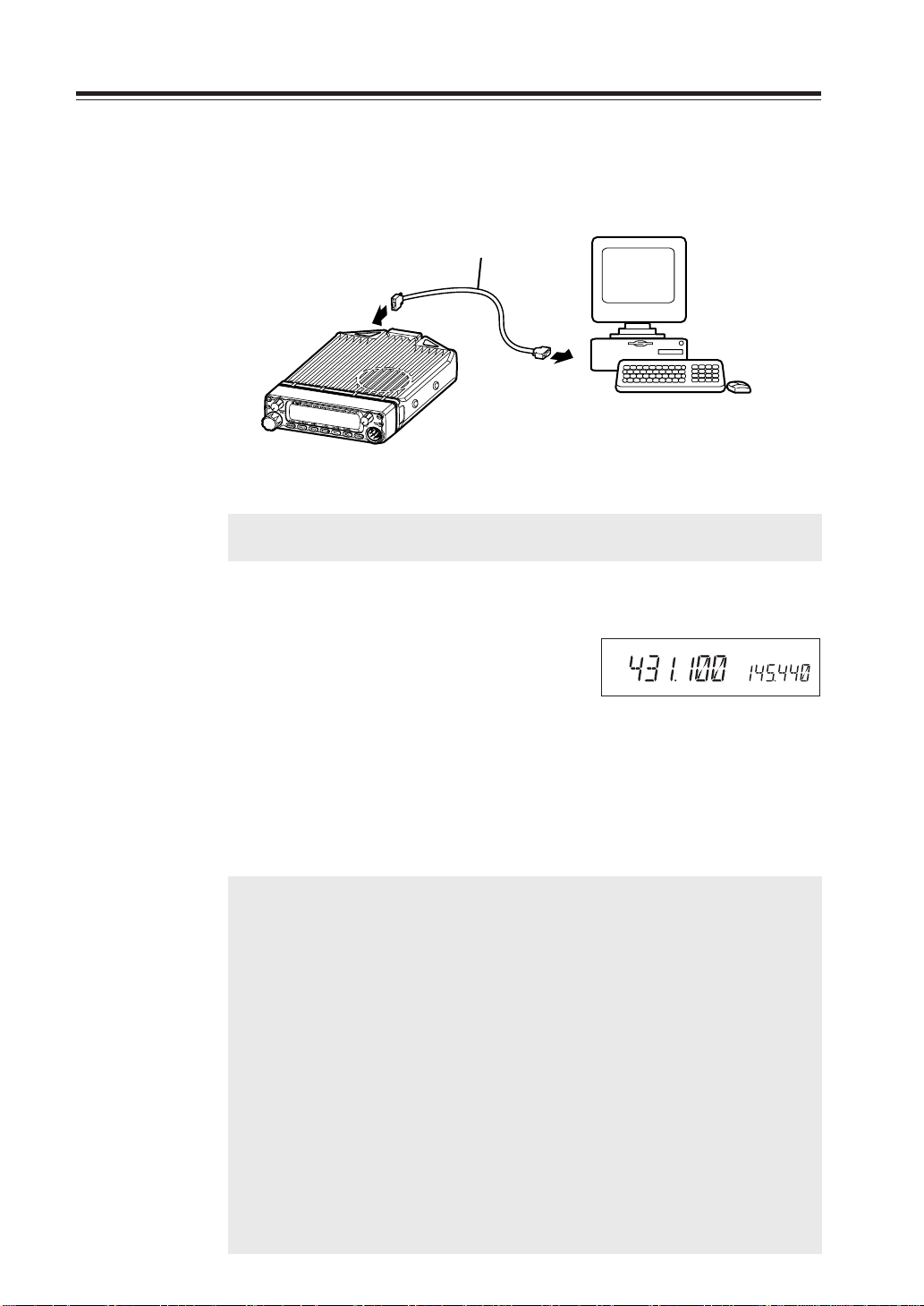
When using EJ-50U
Connect EJ-50U with a personal computer.
1. Connect EJ-50U and DSUB connecter to this unit following the figure below.
A sheet attached to the place meant for DSUB connecter can be removed easily by
pressing from inside.
Special Functions
W1
EJ-50U
Cushion
CN3
D-SUB connecter
W2
CN4
2. Insert DSUB connecter W1 into EJ-50U.
3. Insert W2 of EJ-50U into CN4 of this unit.
Hexagon screw
Clip washer
EJ50U should not mount on the chassis.
49
Page 22
Special Functions
4. Connect EJ-50U with a personal computer.
Connect DSUB connecter on the rear panel and a personal computer with a straight
cable.
RS-232C
straight cable
Personal computer
IMPORTANT: Between DSUB and a personal computer, use 9-pin RS-232C straight
cable (male-female).
Packet Mode Setting
1. Press the FUNC key. While [F] icon is on, press
the H/L and SQL keys. [TNC] lights up on the
display and the unit enters packet mode.
By the same operation, [TNC] lights off, the
unit exits from packet mode and the display
returns to the normal status.
2. Use the computer keyboard to send designated
commands from your PC to start packet communication.
NOTE: • Conditions of communication with a PC terminal.
Please use PC commands to program the following.
Data Speed (Transfer Rate) : 9600bps
Data Length : 8 bit
Parity Bit : None
Stop Bit : 1 bit
Flow Control : Xon/Xoff
• What have been programmed from a PC are stored in memory even after the
TNC unit is removed from the transceiver.
• This TNC unit is not equipped with all the functions an external TNC may have
(Some functions may be limited).
IMPORTANT: • Packet communication is easy to be affected by transmission and re-
ception environment and especially in 9600bps packet mode, commu-
nication error may easily occur unless all segments of S-meter are dis-
played.
• While in packet mode or geolocating communication mode, tones or
codes are not output even if Tone setting or DCS setting is programmed.
TNC
50
Page 23

APRS
Install an optional TNC unit EJ-50U and an external GPS receiver to operate this function.
APRS (Automatic Packet/Position Reporting System) is a pro gram software registered as a trademark of Bob Bruninga, WB4APR. W ith this pro gram, you may trace a mobile station on the map in
a computer.
For tracing a mobile station, y ou may need a PC installed with APRS, this unit (transceiver), TNC
(EJ-50U). You may also need a GPS receiver, which catches a signal from a satellite and lets you
know where you are.
APRS will reconstruct NMEA (National Marine Electronics Association) data message received
from a GPS receiver. For detailed information, please see the Internet web page regarding APRS.
NOTE: GPS means Global Positioning System.
APRS Setting
APRS needs a TNC unit EJ-41U, a GPS receiver and a PC installed with APRS software. Select an
external GPS receiver compatible with NMEA system.
Configuration NMEA: NMEA-0183, 4800bps/Parity Bit none/Data Length 8bit/Stop Bit 1bit
For connection
Please refer to the chapter of packet communication for EJ-50U installation and connection
with a PC.
Special Functions
1. Connect a GPS receiver to CN5 connecter inside of this unit using the provided
wiring cable with some modification.
(Modification/connection of the wiring cable to the terminal is as follows)
Ensure the tube of the wiring cable
goes through the slot on the chassis.
Black Red
CN5
Red
DATA output (GPS receiver output)
GND (GND of GPS receiver)
Black
UX1290A
GPS receiver
DSUB-9 pin
Notebook PC
This unit
NOTE: • You may remove the PC after setting is finished.(What has been pro-
grammed is stored in the TNC unit. To change settings, reconnect it
before setting.)
• Setting of call sign of your station, communication speed and Beacon
transmission time separation may be changed by the TNC clone of this
unit without using a PC.
51
Page 24

Special Functions
For operation
For detailed information, please see a list of commands and
an instruction manual of EJ-50U.
TNC
1. Boot up the terminal software on the PC, press
the FUNC key and press the H/L key while [F]
icon is on. [TNC] lights up on the display and
the unit enters Geolocating communication
mode.
2. Initial screen of TNC appears on the PC.
3. Set communication speed of radio packet from
the command mode (cmd:).
[Example cmd: HB 1200 or 9600]
4. Register call sign of your station.
[Example cmd: MY *****]
5. Set communication speed of the GPS port.
[Example cmd: GB 4800]
6. Set automatic transmission time separation of
GPS data.
[Example cmd: LOC E 3]
7. When location data etc. is received from the
GPS receiver, it will be automatically transmitted with a programmed time separation.
Geolocating communication mode
TASCO Radio Modem
AX.25 Level 2 Version 2.0
Release 03/Dec/99 3Chip ver 1.08
Checksum $04
cmd:HB 1200
HBAUD was 1200
cmd:MY JA1234
MYCALL was NOCALL
cmd:GB 4800
GBAUD was 4800
cmd:LOC E 6
LOCATION was EVERY 0
cmd:
Example of PC display
52
8. By pressing the FUNC key and then the H/L
key, TNC will be turned off and transmission
will also be stopped.
9. By turning on TNC again, automatic transmis-
sion will resume following the previous settings.
IMPORTANT: • While using APRS software, header setting for monitoring should be OFF.
(Input: cmd: LTMH OFF)
• Please use this unit and a GPS receiver reasonably apart from each other.
Page 25
Special Functions
TNC Clone
This feature enables setting change required for APRS function without connecting to a PC.
Please use this feature when setting change is desired while APRS function is in operation.
Setting change is available for call sign of your station, communication speed and data transmission time separation (Setting is made in setting mode).
1. Press the FUNC key and then press the H/L
key while [F] icon is on (Enter packet mode).
2.
Press the CALL key with the FUNC key pressed.
The display will sho w [TNCLON] and data programmed in setting mode for call sign of your
station, communication speed and data transmission time separation are transmitted.
3. Upon completion of data transmission, the dis-
play shows [PASS].
Turning off the unit will finish clone mode and
restore the normal packet mode.
TNC
TNC
Data is under transmission
TNC
Completion of data transmission
53
Page 26

Special Functions
Remote Control Operation (EMS-57 Only)
The transceiver can be controlled remotely by operating the DTMF keys on the microphone. Frequencies can also be entered directly through the key pads.
1
DTMF
LOCK
2
OFF
OFF
List of Remote Control Keys
3
No.
Key Function
1 DTMF
2 LOCK
3
DTMF/REMOTE
Enter the remote command or the frequency.
Press LOCK to prevent the transceiver from accepting
remote control inputs from the microphone.
To operate remote control, press REMOTE.
Key
Transceiver corresponding key
Function Page
0-9 – Direct frequency input –
A V/M Memory channel access 19
B CALL Call channel access 23
C SET mode SET mode access (Note 1) 26
D
FUNC+BAND
Switching reception band 34
* Press and hold SQL Monitor function 24
# BAND Switching MAIN band 15
0 H/L Switching transmission output 25
(Note 1) To change the SET mode menu, press the UP and DOWN keys at the top. To change its
contents, press the * and # keys. Press PTT key or C key to return to the frequency display.
54
Page 27

Special Functions
Entering a frequency directly
Frequencies can be entered directly by pressing the numerical keys of the microphone.
• Range of frequencies to be input
87.500 - 107.995MHz (WFM reception)
144.000 - 145.995MHz
430.000 - 439.995MHz
1. Set the microphone DTMF/REMOTE switch to the REMOTE position.
2. DTMF keys can be used to enter from the 100MHz digit.
(Ex.) When setting 144.20 MHz with the tuning step set to 20kHz.
Enter 1 4 4 2 0
After entering the fifth digit a slightly longer beep is emitted and the entry is completed.
3. Canceling an entry before it is completed. Press PTT key or C key.
Entry method depending on tuning step
Depending on the set tuning step, digit entry may be necessary to the 1 kHz digit. In some cases
entry to the 10 kHz digit is sufficient. For cases in which digit entry is only necessary to the 10 kHz
digit some digit keys were not accepted.
The relationship between the tuning step and input method is as follows.
Tuning step
5.0 kHz
8.33 kHz
10.0 kHz 10 kHz Completion after input of the 10 kHz digit.
12.5 kHz 10 kHz 0···00.0, 1···12.5, 2···25.0, 3···37.5, 4···invalid
15.0 kHz 10 kHz Completion after input of the 10 kHz digit.
20.0 kHz 10 kHz Completion after input of the 10 kHz digit.
25 kHz 10 kHz 0···00.0, 2···25.0, 5···50.0, 7···75.0,
30 kHz 10 kHz When you input the 10 kHz digit, the 1 kHz digit set as follows.
50 kHz 10 kHz
Entry
completion digit
1 kHz Completion after input of the 1 kHz digit.
When you input the 10 kHz digit, the 1 kHz digit set as follows.
5···50.0, 6···62.5, 7···75.0, 8···87.5, 9···invalid
When you input the 10 kHz digit, the 1 kHz digit set as follows.
Other entries are invalid.
When you input the 10 kHz digit, the 1 kHz digit set as follows.
0···00.0, 5···50.0
Final digit selection
55
Page 28

Maintenance / Reference
Reset
Resetting the unit returns all programmed contents to their factory default setting.
1. Press the PWR key for more than 1 second with
the FUNC key pressed to turn the power on.
2. All segments of the LCD will be displayed, then
default settings are displayed.
NOTE: While holding the FUNC key down, turn the power on. All segments of the LCD will be displayed,
then default settings are displayed.
IMPORTANT: While holding the FUNC key down, turn the power on. All segments of the LCD will be
displayed, then default settings are displayed.
AM
MiLo
Nar
SQL
BUSY BUSY1 3 5 7 9
All LCD segments
DCS
SUB
TNC
Factory Default Settings
DR-620T DR-620E DR-620TA
MAIN band VHF VHF VHF
VFO frequency (VHF) 145.00MHz 145.00MHz 165.00MHz
(UHF) 445.00MHz 435.00MHz 460.00MHz
CALL frequency (VHF) 145.00MHz 145.00MHz 145.00MHz
(UHF) 445.00MHz 435.00MHz 460.00MHz
Memory channel - - Offset direction - - Offset frequency (V/U) 600kHz/5MHz 600kHz/7.6MHz 600kHz/5MHz
Channel step 5kHz 12.5kHz 5kHz
Channel step (FM) 100kHz 100kHz 100kHz
Tone-squelch setting - - Tone frequency 88.5Hz 88.5Hz 88.5Hz
DCS setting - - DCS code 023 023 023
Output power HI HI HI
Scan resuming condition
Beep volume setting 2 2 2
Time-Out-Timer OFF OFF OFF
TOT penalty OFF OFF OFF
APO OFF OFF OFF
Tone burst sound setting ALERT 1750Hz ALERT
Clock shift setting OFF OFF OFF
Bell setting OFF OFF OFF
Busy-Channel-Lock-Out setting
Theft Alarm setting OFF OFF OFF
Display color setting 1 (Amber) 1 (Amber) 1 (Amber)
Dimmer setting 4 4 4
Squelch level 02 02 02
timer timer timer
OFF OFF OFF
R
56
Page 29

Maintenance / Reference
Troubleshooting
Please check the list below concluding that the transceiver is faulty.
If a problem persists, reset the transceiver. This can sometimes correct erroneous operation.
Problem
Power is on, nothing
appears on the
Display
Display is too dim.
No sound comes
from the speaker.
The unit does not
receive.
Keys and the dial do
not function.
Possible Causes
a. + and - polarities of power
connection are reversed.
b. Fuse is blown.
c. ACC power supply is
connected but is OFF.
Dimmer setting is "LAMP 1 - 3."
a. The volume knob is rotated
too much counter-clockwise.
b. Squelch is muted.
c. Tone or DCS squelch is
active
d. PTT key of the microphone
is pressed for transmission.
e. External speaker is
connected.
Key-lock function is activated
([ ] is on).
Potential Solutions
a. Correctly connect the red lead
and the black lead of the DC
power cable provided re7)
spectively to the plus terminal and
the minus terminal.
b. Check and solve the problem
resulting in blown fuse and
replace it with a new one with the
rated capacity.
c. Turn on the ACC power supply.
Make the dimmer setting "LAMP 4."
a. Set the volume knob properly.
b. Decrease squelch level.
c. Turn tone or DCS squelch off.
d. Immediately turn off the PTT key.
e. Pull the jack off the terminal of the
external speaker.
Cancel key-lock function.
Rotating the dial will
not change memory
channel.
Pressing the
UP/DOWN key will
not change
frequencies or
memory channels.
PTT key is pressed
but transmission
does not occur.
a. No memory is programmed.
b. The unit is in CALL mode.
a. The unit is in CALL mode.
b. Lock switch is ON.
a. Microphone terminal is not
properly inserted.
b. Antenna is not connected.
c. SHIFT is set for OFF band
transmission.
d. The unit is in SUB band
reception mode.
a. Program memory.
b. Press V/M key for memory mode.
a. Switch to VFO mode or memory
mode.
b. Turn off the Lock switch.
a. Properly insert the microphone
terminal.
b. Properly connect the antenna.
c. Cancel SHIFT or set within the
band.
d. Switch to the MAIN band.
57
Page 30

Maintenance / Reference
Problem
Packet
communication does
not function.
APRS does not
function.
The unit does not
enter V-V/U-U mode.
IMPORTANT: When reception frequencies fall in any one of the formulas below, the unit may
receive non-modulated signal.
This is due to the structure of frequencies of this unit and not a malfunction of the
unit.
• (Reception frequency on the MAIN side - 45.1MHz )
• (FM reception frequency + 10.7MHz x 4) : UHF reception frequency - 90.2MHz
• (FM reception frequency + 10.7MHz x 5) :UHF reception frequency
• (Reception frequency in the UHF band - 45.1MHz) x 2
Possible Causes
a. TNC is not connected or set
properly.
b. The unit is not in the packet
mode.
c. The squelch is open.
d. The data transmission speed
is not configured.
e. A PC cable other than the
straight type is used.
a. The unit is not in the packet
mode.
b. The unit is not configured for
automatic transmission.
c. The squelch is open.
d. The GPS receiver is not
geolocating.
Either the MAIN or SUB side is
in memory mode.
: Reception frequency on the SUB side - 43.4MHz (In u-u)
- (Reception frequency in the VHF band - 21.7MHz) x 6 : 45.1MHz
Potential Solutions
a. Make sure the connections and
configurations are properly set.
b. Switch to the packet mode.
c. Adjust the squelch level where it
will open by a reception signal.
d. Adjust the speed by the PC.
e. Use a straight type PC cable.
a. Switch to the packet mode.
b. Use the PC to set transmission
time separation.
c. Adjust the squelch level where it
will open by a reception signal.
d. Wait until the GPS receiver
properly geolocates.
Switch to VFO mode.
Optional accessories
• EMS-57 DTMF equipped microphone
(This comes standard with the DR-620T)
• EJ-50U TNC unit
58
• EMS-53 Microphone
(This comes standard with the DR-620E)
Page 31

Transmitter Chart
DR-620T, DR-620E
ANT
DR-620T
144.000〜147.995MHz
430.000〜449.995MHz
Power
amplifier
RD70HVF1
DR-620E
144.000〜145.995MHz
430.000〜439.995MHz
amplifier
Excitation
2SK2975
amplifier
Excitation
2SK3074
Maintenance / Reference
EJ-50U
GPSinput
2SC5066
Bufferamplifier
144MVCO
2SK508K2
TGT0210Q
TMT0211Q
PCinput
2SC5226
Bufferamplifier
PLL
M64076AGP
21.25MHz
NJM2902V
Lowpassfilter
Low-frequency
amplifyinglimiter
MIC
2SC5066
Bufferamplifier
430MVCO
2SK508K2
59
Page 32

Maintenance / Reference
Specification
General
Frequency coverage
DR-620T 87.500 - 107.995MHz (WFM)
108.000 - 135.995MHz (AM RX)
136.000 - 173.995MHz (RX)
144.000 - 147.995MHz(TX)
335.000 - 479.995MHz (RX)
430.000 - 449.995MHz (TX)
DR-620E 87.500 - 107.995MHz (WFM)
144.000 - 145.995MHz (RX, TX)
430.000 - 439.995MHz (RX, TX)
Operating mode 16K0F3E (Wide mode), 8K50F3E (Narrow mode)
Frequency resolution 5, 8.33, 10, 12.5, 15, 20, 25, 30, 50, 100kHz
Number of memory channels
Antenna impedance 50Ω unbalanced
Power requirement 13.8V DC +/-15% (11.7 to 15.8V)
Ground method Negative ground
Current drain Receive: 0.6A(Max.), 0.4A(Squelched)
Operating temperature
Frequency stability +/- 2.5ppm
Dimensions 140(w) - 40(h) - 185(d) mm (w/o knobs)
Weight Approx. 1.0kg
Transmitter
Output power High:50W(VHF), 35W(UHF)Mid:10WLow:5W
Modulation system Variable reactance frequency modulation
Maximum frequency deviation
Spurious emission -60dB
Adjacent channel power
Modulation Distortion Lass than 3%
Microphone impedance
Receiver
Sensitivity -14dBu for 12dB SINAD
Receiver circuitry Double conversion superheterodyne
Intermediate frequency
Squelch sensitivity -18dBu
Selectivity(-6dB/-60dB)
Spurious and image 70dB
rejection ratio
Audio output power 2.0W (8Ω,10%THD)
*All specifications are subject to change without notice or obligation.
200
Transmit: 11.0A
- 10 °C to 60 °C
+/- 5kHz (Wide mode) +/-2.5kHz (Narrow mode)
-60dB
2kΩ
1st 21.7MHz 2nd 450kHz (VHF)
1st 45.1MHz 2nd 455kHz (UHF)
12kHz/24kHz
DR-620T, DR-620E
60
Page 33

MEMO
61
 Loading...