

Page 1
ALINCO,INC.
Head Office: Shin-Dai building 9th Floor
2-6, 1-Chome, Dojimahama, Kita-ku,
Osaka 530-0004, JAPAN
Phone:+81-6-4797-2136 Fax:+81-6-4797-2157
E-mail:export@alinco.co.jp0
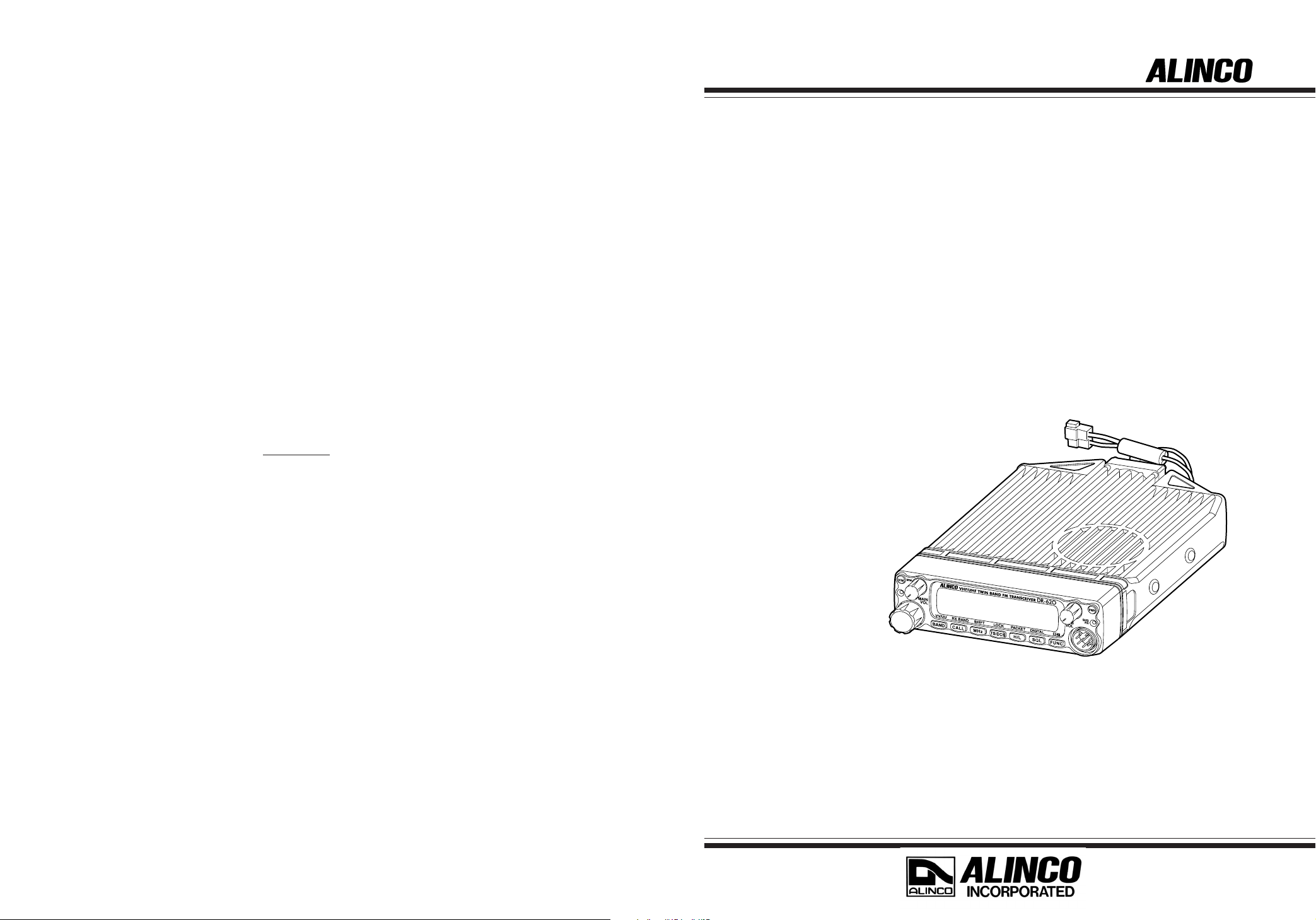
VHF/UHF FM TRANSCEIVER
DR-620T/E
Instruction Manual
Printed in Japan
Copyright Alinco,Inc. 2002 PS00000
Thank you for purchasing your new Alinco transceiver.
This instruction manual contains important safety and operating instructions. Please read this
manual carefully before using the product and keep it for future reference.
Page 2

NOTICE
Compliance Information Statement
This equipment has been tested and found to comply with the limits for a Class B digital device,
pursuant to part 15 of the FCC Rules.
These limits are designed to provide reasonable protection against harmful interference in a residential
installation. This equipment generates, uses, and can radiate radio frequency energy and, if not installed
and used in accordance with the instruction manual, may cause harmful interference to radio communications. However, there is no guarantee that interference will not occur in a particular installation. If this
equipment does cause harmful interference to radio or television reception, which can be determined by
turning the equipment off and on, the user is encouraged to try to correct the interference by one or
more of the following measures:
• Reorient or relocate the receiving antenna.
• Increase the separation between the equipment and receiver.
• Connect the equipment into an outlet on a circuit different from that to which the receiver is
connected.
• Consult the dealer or an experienced radio/TV technician for help.
Tested to Comply
With FCC Standards
VHF/UHF FM Transceiver DR-620T/E
This device complies with Part 15 of the FCC Rules. Operation is subject
to the following two conditions: (1) This device may not cause harmful
interference, and (2) this device must accept any interference received,
including interference that may cause undesired operation.
U.S. Representative: ATOC Amateur Distributing LLC
23 South High Street
Covington, OH 45318
Telephone: 937-473-2840
FOR HOME OR OFFICE USE
Information in this document is subject to change without notice or obligation. All brand names and
trademarks are the property of their respective owners. Alinco cannot be liable for pictorial or typographical inaccuracies. Some parts, options and/or accessories are unavailable in certain areas. Changes
or modifications not expressly approved by the party responsible for compliance could void the user's
authority to operate the equipment.
Conformity Information
In case the unit you have purchased is marked with a CE symbol, a copy of relative conformity certificate or document can be reviewed at http://www.alinco.com/usa.html.
Copyright © 2002 All rights reserved. No part of this document may be reproduced, copied, translated
or transcribed in any form or by any means without the prior written permission of Alinco. Inc., Osaka,
Japan. English Edition Printed in Japan.
Page 3

Contents
Before operating the transceiver ............. 3
Attention ................................................................ 3
Introduction ...............................................3
New and Innovative Features...................4
Standard Accessories .............................. 5
Initial Installation ....................................... 6
For a base station set up ....................................... 6
For a mobile station set up .................................... 7
Location .................................................... 7
Installing a Mobile Antenna....................... 7
Installing the Transceiver .......................... 7
Front Panel ............................................................ 8
External power supply control function .................. 9
Power supply voltage display function................. 10
Part Names and Functions ..................... 11
Front Panel ...........................................................11
Rear Panel........................................................... 12
Display ................................................................. 13
Microphone EMS-53 (Standard) .......................... 14
Basic Operations.....................................15
Turning the unit on and off................................... 15
Switching the MAIN band .................................... 15
Audio Volume level setting .................................. 15
Squelch level setting............................................ 15
Squelch level setting on the SUB side .... 15
VFO mode ........................................................... 16
Change frequency by the channel step .. 16
Change frequency by 1 MHz step........... 16
Setting the channel step ...................................... 17
Shift Direction and Offset frequency setting ........ 18
Memory Mode...................................................... 19
Recalling a memory channel................... 19
How to program memory ........................ 20
Memory channel deleting .................................... 21
Programmable data in the memory channel ...
21
Channel name (Alphanumeric) registration function.....
CALL mode .......................................................... 23
To recall a CALL channel..................................... 23
To receive signals ................................................ 23
Monitor function ................................................... 24
Reverse function.................................................. 24
To transmit ........................................................... 25
Switching the transmission power........... 25
22
Parameter Setting Mode .........................26
A list of the setting mode ..................................... 26
To use the setting mode ...................................... 27
Channel Step setting ........................................... 28
Scan Type............................................................ 28
Beep Sound ......................................................... 28
Time-Out-Timer.................................................... 29
TOT Penalty......................................................... 29
Setting the TOT penalty time .................. 29
APO-Auto Power OFF ......................................... 30
Tone-Burst Frequency ......................................... 30
Clock shift ............................................................ 30
Bell....................................................................... 31
Busy-Channel-Lock-Out (BCLO) ......................... 31
Theft Alarm .......................................................... 31
Illumination color setting ...................................... 32
Dimmer ................................................................ 32
Call sign setting (In packet operation) ................. 32
Transmission speed setting (In packet operation) ........
Beacon interval setting (In geolocating communication)
33
33
Useful functions ......................................34
Reception band switching.................................... 34
V-V/U-U simultaneous reception ......................... 34
Single-band mode ............................................... 35
VFO Auto-program setting function ..................... 35
SCANNING FUNCTION ...................................... 36
•VFO Scan .............................................. 36
•Memory Scan ........................................ 37
•Skip-channel setting .............................. 37
•Program Scan........................................ 38
•Tone Scan.............................................. 38
•DCS scan .............................................. 39
KEY-LOCK FUNCTION ....................................... 39
TONE BURST...................................................... 39
Narrow-band mode .............................................. 40
AM receiver mode ............................................... 40
1
Page 4

Contents
Selective Communication ...................... 41
Tone-squelch (CTCSS) and DCS ........................ 41
DET setting ............................................. 42
Digital voice communication (DR-620T only)..
43
Special Functions ................................... 44
THEFT ALARM .................................................... 44
To connect, set and operate ................... 44
How the alarm operates.......................... 45
Setting alarm starting time ...................... 46
Cable Clone ......................................................... 47
Connection.............................................. 47
Setting on the Slave side ........................ 47
Setting on the Master side ...................... 48
Packet Communication........................................ 49
When using EJ-50U ................................ 49
Packet Mode Setting............................... 50
APRS ................................................................... 51
APRS Setting .......................................... 51
For operation........................................... 52
TNC Clone .............................................. 53
Remote Control Operation (EMS-570 only)......... 54
List of Remote Control Keys ................... 54
Entering a frequency directly .................. 55
Entry method depending on tuning step . 55
Maintenance / Reference ........................56
Reset ................................................................... 56
Factory Default Settings.......................... 56
Troubleshooting ................................................... 57
Optional accessories ........................................... 58
Transmitter Chart................................................. 59
Specification ........................................................ 60
2
Page 5
Before operating the transceiver
Attention
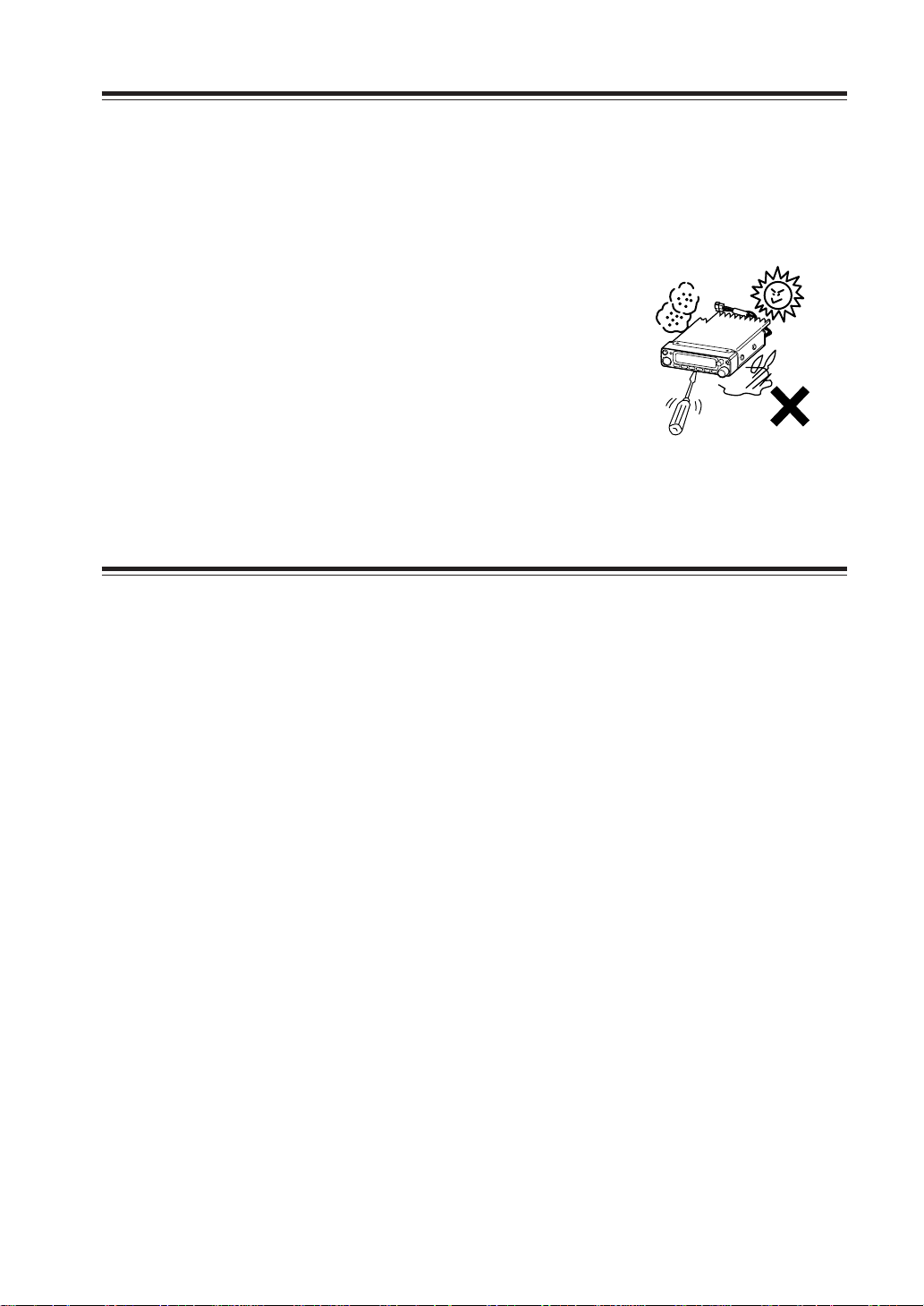
• Do not remove the case or touch the interior components.
Tampering can cause equipment trouble.
• Do not use or keep the transceiver where it is exposed to direct sunlight, dusty
places, or near sources of heat.
• Keep the transceiver awa y from TV's or other equipment when it interferes with reception.
• When transmitting for long periods of time at high
power, the transceiver might overheat.
• Turn the power off immediately if the transceiver
emits smoke or strange odors. Ensure the transceiver
is safe, then bring it to the nearest Alinco service
center.
Introduction
Thank you very much for purchasing this excellent Alinco transceiver. Our products
are ranked among the finest in the world. This radio has been manufactured with
state of the art technology and it has been tested carefully at our factory. It is designed to operate to your satisfaction for many years under normal use.
PLEASE READ THIS MANUAL COMPLETELY TO LEARN ALL THE FUNCTIONS THE PRODUCT OFFERS. WE MADE EVERY ATTEMPT TO WRITE
THIS MANUAL TO BE AS COMPREHENSIVE AND EASY TO UNDERSTAND
AS POSSIBLE. IT IS IMPORTANT TO NOTE THAT SOME OF THE OPERATIONS MAY BE EXPLAINED IN RELATION TO INFORMATION IN PREVIOUS CHAPTERS. BY READING JUST ONE PART OF THE MANUAL, YOU
RISK NOT UNDERSTANDING THE COMPLETE EXPLANATION OF THE
FUNCTION.
3
Page 6

New and Innovative Features
Your new radio features some of the most advanced functions and reliable engineering
available anywhere. The ALINCO design philosophy is focused on developing innovative usable features, including the following:
• A large, color-selectable display panel
Very clear display of frequency, memory name etc. ensure convenient operation.
• Excellent frequency stability
By using a temperature compensated crystal oscillator (TCXO), deviation less than
+/- 2.5ppm is realized.
• V-V/U-U function
Simultaneous reception of 2 signals within a same frequency band is possible (Excluding FM broadcasting band).
• High-quality materials are used throughout the product and a huge heat sink around
the chassis ensures stable and durable operation.
• AM Air-band reception capability (T models only)
• 200 fully programmable memory channels with alphanumeric memory channel labels
• CTCSS, DCS and 5 different Tone-Bursts are standard for selective calling and repeater access worldwide.
• Applicable for APRS®/Packet communication (With the optional EJ-50U installed)*
• Theft Alarm feature
• Auto-Programming VFO for easier repeater access
• Cable-Clone function
• Power supply voltage display function
• Narrow-FM mode
• Microphone remote control function (EMS-57 microphone may be on option depending the version.)
• Front-Control unit separation
APRS®isatrademarkofMr.BobBruninga,WB4APR.
*
4
Page 7
Standard Accessories
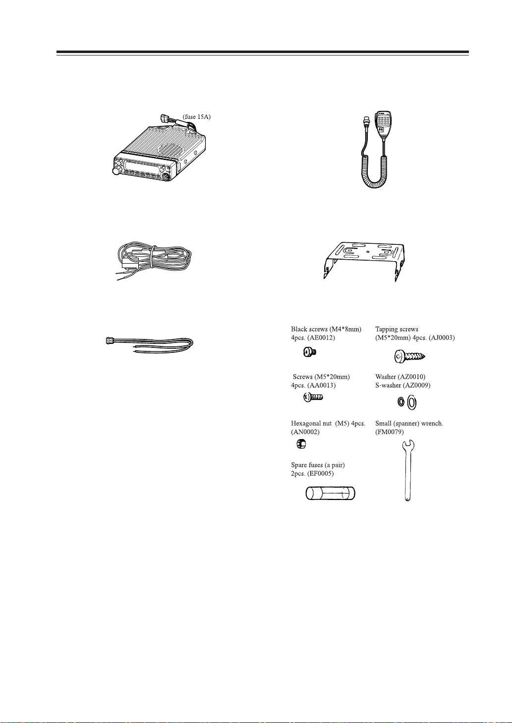
Carefully unpack to make sure the following items are found in the package in addition to this manual:
• Transceiver
• DC power cable with fuse holder (UA0038)
•ACC cable (UX1290A)
• Microphone EMS-53 or EMS-57 (with
DTMF keypad)
• Mobile mounting bracket. (FM0078Z)
• Hardware kit for bracket
• Theft Alarm stickers 2pcs. (PR0454)
• Instruction manual (this manual)
•
Warranty certificate (T version only) (PH0009A)
• EJ-50U manual & disc (with TNC version only)
The standard accessories may vary slightly depending on the version you have purchased. Please contact
your local authorized Alinco dealer should you have any questions. ALINCO and authorized dealers are
not responsible for any typo graphical errors there may be in this manual. Standard accessories ma y change
without notice.
Warranty Policy:
Please refer to any enclosed warranty information or contact your authorized Alinco dealer / distributor for the warranty policy.
5
Page 8
Initial Installation
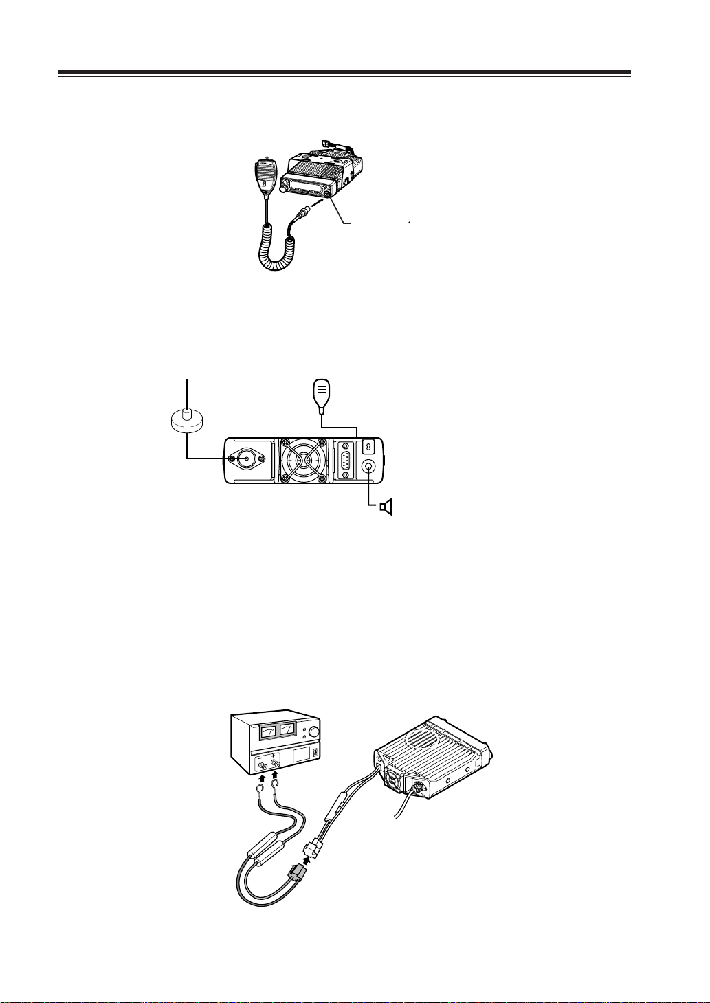
e
Connect the microphone to the front panel of the transceiver.
Microphon
connector
Connect antenna port to a 50 ohm antenna that covers the 2 m/70 cm bands, using good quality
50 ohm coaxial cable.
Antenna
Microphone
rear panel
External speaker
(if used)
For a base station set up
The Transceiver requires a 12-13.8VDC negative grounded power source.
Use a regulated power supply capable of providing continuous current of 12A or more.
Power supplies that do not meet those specifications may cause malfunction and/or damage to the
radio and will void the warranty. Alinco offers excellent communication-grade power supplies as
optional accessories. Please contact your local authorized Alinco dealer.
DC
power supply
Black lead
Red lead
DC power cable
6
Page 9
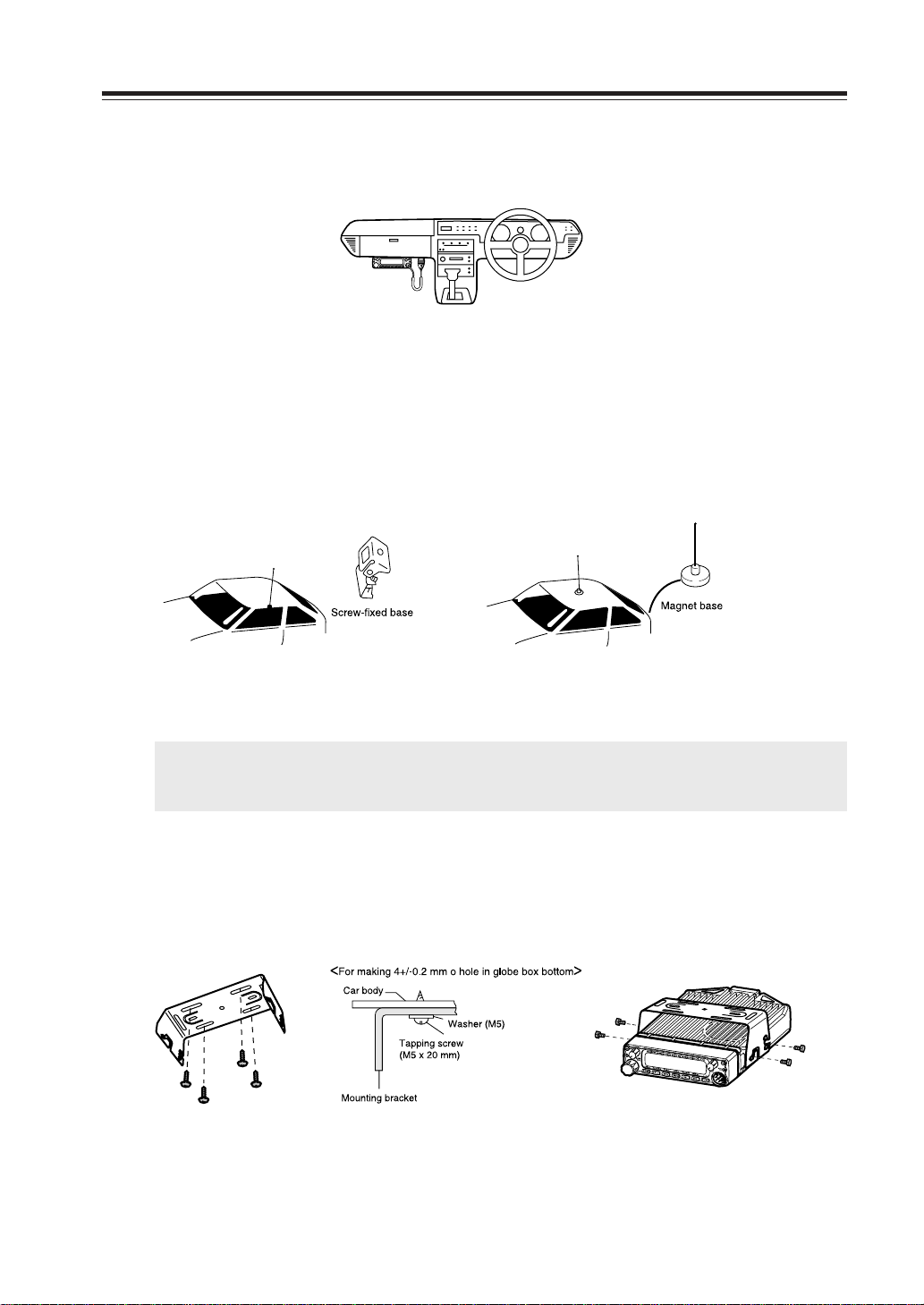
For a mobile station set up
b
Location
The transceiver ma y be installed in an y position in y our car, where the controls and microphone are
easily accessible and it does not interfere with the safe operation of the v ehicle or the performance
of the set. If your vehicle is equipped with air bags, be certain your radio will not interfere with
their deployment. If you are uncertain about w here to mount the unit, contact y our v ehicle's manufacturer. Please refer the next page for front control unit setting.
Installing a Mobile Antenna
Initial Installation
Use a 50 ohm coaxial cable to connect the antenna. Mobile antennas require an appropriate mounting base for proper installation and operation. For more information, see the documentation for
your antenna.
IMPORTANT: After installing your antenna, ensure that you have the best possible SWR reading.
High RF environments can cause severe damage to your unit. Ensure that you are not
in a high RF environment when operating the transceiver.
Installing the Transceiver
See the figure on the below.
b
a
a
7
Page 10

Initial Installation
Front Panel
The main unit can be set with either side facing up.
Fix the front panel as you prefer.
1. Slide the front panel while keeping the knob pressed.
Front panel
2. Turn the front panel
Main unit
Knob
3. Match the catch in the main unit with the slot in the front panel and fit the front
panel into the main unit.
Catch
Slot
4. Slide the front panel.
NOTE: By using the optional separation kit EDS-9, you can use the front panel and the main unit in
a separate position. The instruction is provided in the EDS-9.
8
Page 11

External power supply control function
Red: For connection with the ACC power supply
Black: For connection with the grounding wire
Red
CN11
SW11
ON
ACC
ACC external power supply control function is on
Black
In wiring, ensure
the tube comes
right in the slot
WARNING: The connection of cables may involve certain knowledge about the ve-
hicle the unit will be installed. Consult with your car-dealer or service sta-
tion for more information if necessary as we are not responsible of any
damage this installation might cause to your vehicle.
1. Be sure the vehicle has a negative-ground, 12VDC electric system before installa-
tion. Connect the provided DC cable with fuse-holder directly to the battery (red
cable to the positive terminal) to minimize any possible ignition noise. Be sure the
vehicle has a large capacity battery as the use of a transceiver may overload the
electric system of the vehicle.
Initial Installation
2. In addition, if the optional ignition-key ON/OFF feature is desired, use the provided
ACC cable. Remove the cover by unscrewing 4 screws. Connect the ACC cable to
the ACC power jack (CN11) on the rear side of the unit inside, trim the outgoing
cable as shown above, select the ACC switch (SW11) to ACC position and reassemble the cover.
3. Be sure to cut the electric power supply off (by disconnecting the battery cables of
the vehicle) and the ignition key is at OFF position for you and your car's safety.
Connect another end of the ACC cable to the ACC terminal or ACC switch on the
vehicle. Make sure all above sequence has been done properly. Set the vehicle's
electric system back normal.
4. If this option is selected, the unit can be turned on/off either manually or automati-
cally in accordance with the ignition key position.
A: When the ignition key is turned to ACC or ON (start) position with the unit left
turned ON, the unit will turn on automatically and turns OFF when the ignition
key is turned to the OFF position.
B: To manually ON/OFF the power, leave the ignition key to ACC position and use
PWR switch on the unit. If the ignition key is at OFF position the unit won't turn
on. The power consumption, regardless of the ignition key position, of this feature is about 5mA. For operation without this option, use the PWR switch to turn
the unit on/off always.
9
Page 12

Initial Installation
Power supply voltage display function
After connecting the transceiver to the power supply, the supply voltage can be confirmed by pressing the SQL key together with the FUNC k e y. The supply v oltage to the transceiver is then seen on
the display.
The transceiver will return to its normal operation when the power is switched OFF.
The display immediately changes as the voltage supply changes.
It also displays voltage during transmission.
(Example) In case of 13.6V
IMPORTANT: The range of the displayed voltage is only from 7 - 16VDC. Because the displayed
value is estimated, please use a voltmeter when a more precise reading is desired.
10
Page 13

Part Names and Functions
VHF/UHF
TWIN B
AND FM
TRANSCEVER
DR-620
Front Panel
16 32
MW
V/M
MAIN
TX/RX
4
MAIN
VOL
7
VHF/UHF
VV/UU
RX BAND SHIFT LOCK
BAND
CALL MHz
8 9
TWIN B
AND FM
TS/DCS
10 14131211
TRANSCEVER
DR-620
PACKET DIGITAL
H/L SQL FUNC
PWR
SUB
RX
SUB
VOL
SET
•Primary Functions
No.
Key Function
1 PWR key Power turns ON/OFF whenever switch is pressed.
2
Main VOL knob
3
Sub VOL knob
4 Main TX/RX During transmission on the MAIN, illuminates in Red,
indicator and during reception illuminates in Green.
5 Sub RX lamp During reception on the SUB, illuminates in Green.
6 V/M/MW Switches between VFO mode and memory mode.
7 Dial
8 BAND/VVUU Switches the MAIN band to VHF or UHF.
9
CALL/RX BAND
10 MHZ/SHIFT In VFO mode, changes frequency in 1 MHz steps.
11
TSDCS/LOCK
12 HL/ PACKET Switches HI/MID/LOW of transmission power.
13 SQL/DIGITAL Sets the squelch level.
14 FUNC/SET Sets functions.
15
Mic. Connector
Adjusts the volume level on the MAIN band.
Adjusts the volume level on the SUB band.
Changes the frequency, memory channel and various settings.
Switches to CALL Mode.
Sets the tone squelch and DCS setting.
Connects the provided microphone.
5
15
•
Functions which can be activated while [F] appears, after pressing the FUNC Key
No.
Key Function
6 V/M/MW Write in to memory channel.
8
BAND/VVUU
9
CALL/RXBAND
Switches to VV/UU mode.
Switches reception bands.
10 MHZ/SHIFT Sets the shift direction and the offset frequency.
11
TSDCS/LOCK
12 HL/PACKET Accesses the packet communication mode or the
Sets the key lock function.
geolocating communication mode.
13
SQL/DIGITAL
* [F] illuminates when the FUNC key is pressed.
Accesses the digital voice communication mode.
11
Page 14

Part Names and Functions
Rear Panel
•
Functions that can be activated while pressing the FUNC Key
No.
Key Function
1 PWR Reset to factory default settings.
5 V/M/MW Erase the memory.
8 BAND/VVUU Switches to the single band mode.
9
CALL/RXBAND
10 MHZ/SHIFT Switches to wide/narrow mode reception.
11
TSDCS/LOCK
12 HL/PACKET Sets the channel name function.
13 SQL/D Accesses the power supply voltage indication mode.
Accesses the clone function mode.
Switches to the AM reception mode.
• Functions that require continuous pressing to be activated.
No.
Key Function
13 SQL/DIGITAL When pressed for 1 second, the monitor function is on.
(When the shift is set, the reverse function is on.)
14 FUNC/SET When pressed for 2 seconds, accesses the set mode.
4 3 5 2
1
No.
Key Function
1
External Speaker Terminal
2 Power cable Connects to the 13.8VDC power supply.
3 Air-cooling fan
4 Antenna Connector Connect an optional antenna for 50 ohm
5
D-SUB Connector (Optional)
Terminal for optional external speaker.
(Also used for the clone function.)
Cools the unit during transmission. (PTT activation)
impedance. (PL-259 or compatible)
Connects to a personal computer for packet use.
12
Page 15

Display
Part Names of Functions
2 3 4 5 6 7 8 9
1
AM
MiLo
25
24
No.
SQL
BUSY BUSY1 3 5 7 9
23 22 21 20 19 18
Key Function
Nar
DCS
101112 13 14 15
SUB
TNC
R
16
17
1 Appears when FUNC Key is pressed.
2AM Appears during AM reception.
3Mi Appears when transmission power is set to MID.
4Lo Appears when transmission power is set to LOW.
5 Nar Appears when in narrow band reception mode.
6 +/- Appears when setting the shift.
7 Appears when setting the tone squelch.
8 DCS Appears when setting the DCS.
9 SUB Appears when SUB band is on the MAIN side.*
10 Appears when setting the key lock.
11 * Appears when setting the theft alarm function.
12 TNC
13
Appears when in packet mode (Optional EJ-50U required).
Appears when SUB band is in the memory mode or call mode.
14 R Appears when the reverse function is activated.
15 Appears when in the digital voice communication mode.**
16 Appears when setting the bell (pager) function.
17 Indicates the frequency or memory name on the SUB side
18 S Meter Indicates the relative signal strength level of transmission/
reception on the SUB side.
19 Appears when a signal is being received on the SUB side.
20 Indicates the frequency or memory name on the MAIN side.
21 S Meter Indicates the relative signal strength level of transmission/
reception on the MAIN side.
22
.Decimal point
Appears when changing the DCS decode settings.
Disappears when setting the skip.
23 Appears when a signal is being received on the MAIN side.
24 SQL Appears when setting the squelch level.
25 Indicates memory numbers in the memory mode.
*SUB band is the band exclusive for reception when in V-V/U-U.
** T version only. Optional EJ-47U required.
13
Page 16
Part Names and Functions
E
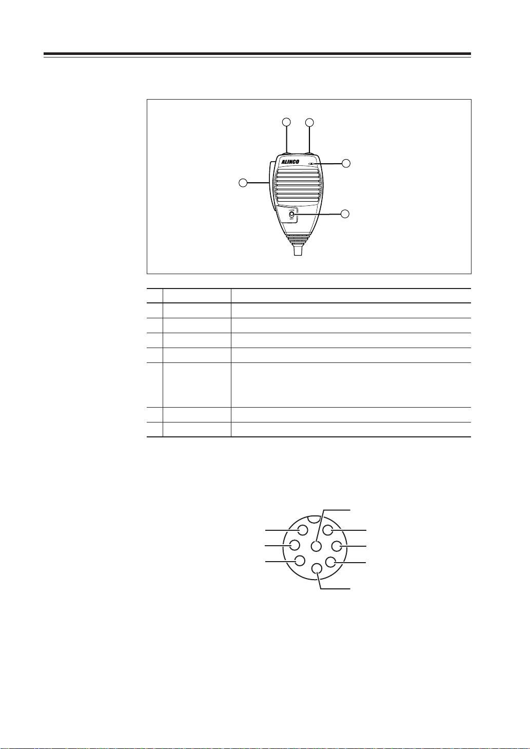
Microphone EMS-53 (Standard)*
2
3
No.
Key Function
1UP
2 DOWN
3 PTT Press the PTT(Push-To-Talk)key to transmit.
4 DTMF DTMF tone keys
DTMF / REMOTE
5
6 Lock Switch Locks out the UP and DOWN keys.
7 MIC Speak here during transmission.
Increase the frequency, memory channel number , or setting v alue.
Decrease the frequency , memory channel number , or setting value.
Set to DTMF when you don’t want to operate remote control functions. So that DTMF keys do not function except
Switch
during transmit to send DTMF codes manually.
1
5
4
14
Mic. Connector Diagram (While looking in the front view of the connector)
GND
1
MIC
PTT
DOWN
* If the version you have purchased contained EMS-57 Multi-function microphone, please
also refer page 54.
2
7
6
8
3
5
4
MIC GND
REMOT
DC 5V
UP
Page 17
Basic Operations
TWIN B
AND FM
RANSCEVER
VHF/U
BAND
CALL MHz
VV/UU
V/M
MAIN
VOL
MW
MAIN
TX/RX
RX BAND SHIFT LOCK
PACK
TS/DCS
H/L
VHF/UHF VHF/UHF TWIN BTWIN BAND FM AND FM TRANTRANSCEVER
DR-620
BAND Key
Turning the unit on and off
By pressing the PWR key the po w er is turned on. By pressing
the PWR key again, the po wer is turned off. Refer page 9 for
external power supply control.
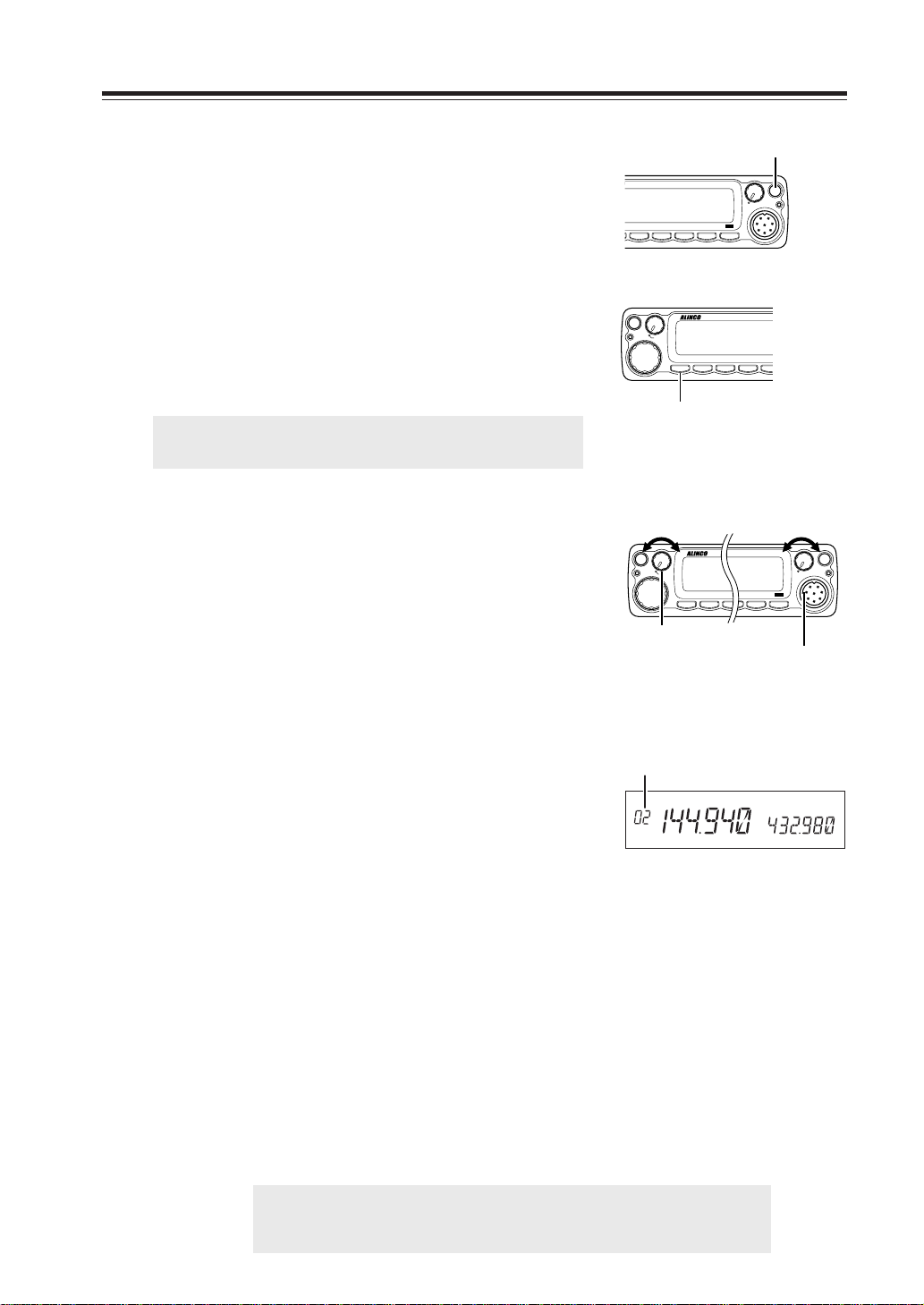
Switching the MAIN band
Repeating to press the BAND key will s witch the MAIN band
between VHF band and UHF band.
The MAIN band allows transmission and reception. The SUB
band only allows reception. The MAIN band and the SUB
band can receive simultaneously.
IMPORTANT: On the SUB side, no setting other than the fre-
quency and S meter is indicated.
Audio Volume level setting
The volume of the MAIN band is adjusted by the VOL knob
on the MAIN side, and the volume of the SUB band by the
VOL knob on the SUB side.
Rotate the VOL knob clockwise to increase the audio level,
counterclockwise to decrease.
Squelch level setting
/UHF
TWIN B
AND FM
TRANSCEVER
DR-620
PACKET DIGITAL
H/L SQL FUNC
SET
SHIFT LOCK
MHz
TS/DCS
Volume
low
high
MW
V/M
MAIN
TX/RX
VHF/U
RANSCEVER
MAIN
VOL
VV/UU
RX BAND SHIFT
BAND
CALL MHz
MAIN side VOL knob
PWR key
PWR
SUB
RX
SUB
VOL
Volume
ET DIGITAL
low
DR-620
SQL FUNC
high
PWR
SUB
RX
SUB
VOL
SET
SUB side VOL knob
Adjust threshold level of the squelch. A squelch eliminates the background noise when a signal is
not received. To set squelch level on the MAIN band side,
1. Press SQL Key.
Squelch level
[SQL] icon appears on the display and the
squelch level will be shown on it.
SQL
2. By rotating the main dial or by using the UP/
DOWN keys on the microphone, adjust the
squelch level to the desired level.
The new squelch lev el will be stored if the pow er
is turned off.
3. When completing the setting, press PTT or any
key on the front panel other than the Band key.
Then the display will return to the original status; or if there are no operations for 5 seconds,
the unit will automatically complete the setting
and the display will return to the original status.
Squelch level setting on the SUB side
To set the squelch level on the SUB side, press the BAND key while [SQL] appears.
NOTE: • 21 levels, between (00) and (20), are available for the squelch level.
(Higher level settings will make the squelch more difficult to open.)
• The default level is 02.
15
Page 18
Basic Operations
K
L
NVHF/UHF TWIN BAND FM TRANSCEVER
DR-620
VFO mode
VFO tuning is set as a default mode at the factory. VFO (variable frequency oscillator) allo ws y ou to change the frequenc y
in accordance with the selected channel step as you rotate the
main dial or by using the UP/DO WN k eys on the microphone.
VFO mode is also used to program the data to be stored in the
memory channels or to change the parameter settings of the
transceiver.
1. Identify the current mode by checking the dis-
play. If “M” or “C” icon is NOT displayed on
it, the unit is already in the VFO mode.
If memories have not been pro grammed, the unit
will not be switched to the memory mode.
2. Otherwise press “V/M” keys until those icons
are gone.
VFO mode
Memory mode
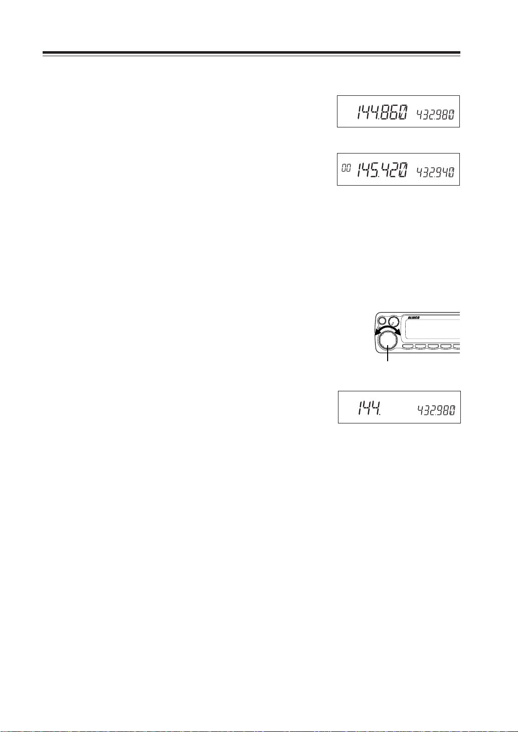
Change frequency by the channel step
Rotate the main dial clockwise to increase the frequency , counterclockwise to decrease. The UP/DOWN keys on the microphone act in the same way.
Change frequency by 1 MHz step
This will enable a quick change of frequency in 1 MHz steps:
1. Press MHz key. The digits after 100 kHz will
disappear from the display.
2. Follow the same sequence as above to change
the value.
Frequency
decrease
V/M
MAIN
TX/RX
Dial
MW
MAIN
VOL
VHF/UHF TWIN BAND FM TRA
Frequency
increase
VV/UU
RX BAND SHIFT LOCK
BAND
CALL MHz
TS/DCS
PAC
H/
16
Page 19
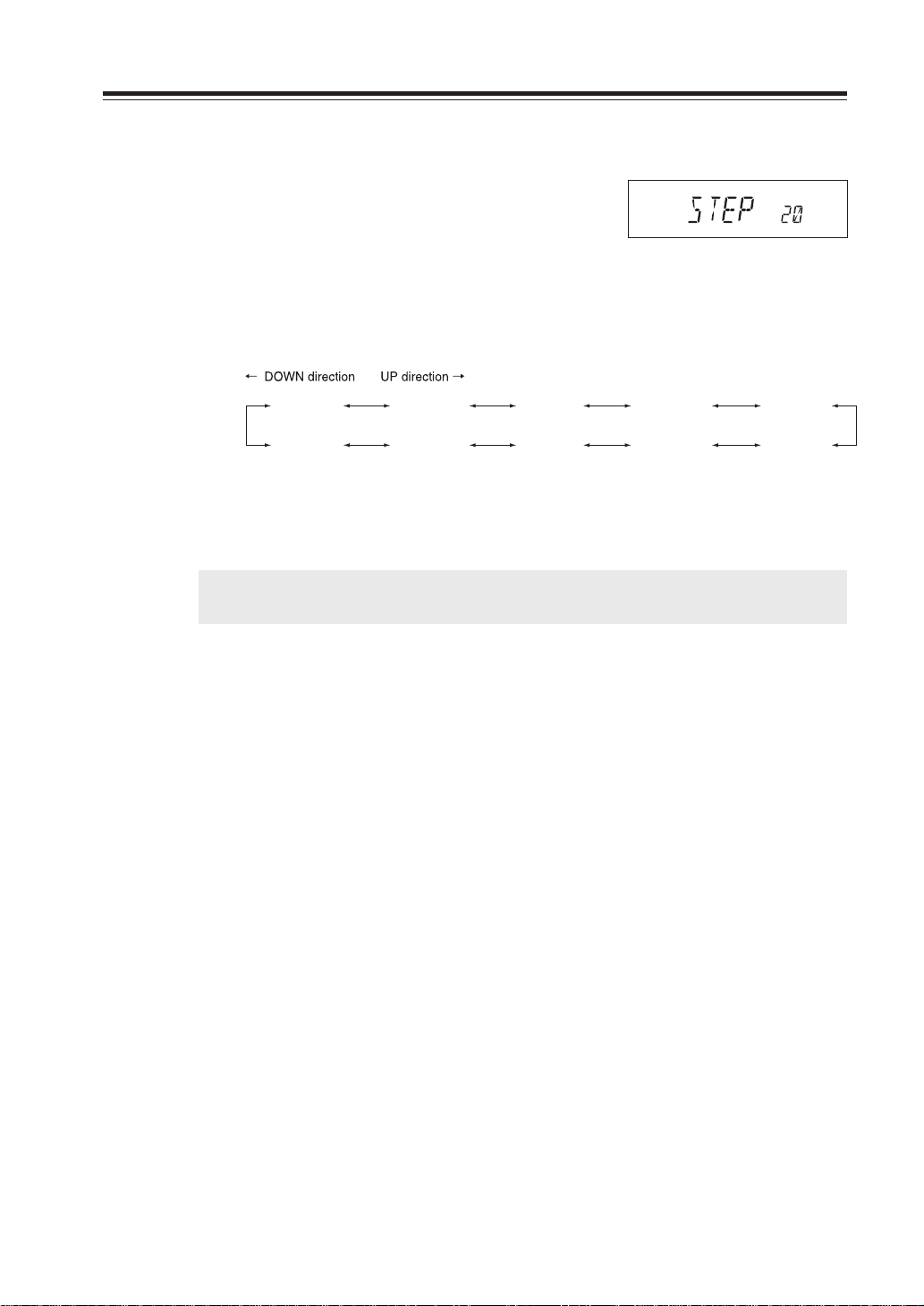
Setting the channel step
1. When the unit is in VFO mode, enter into the
SET mode and select the channel step setting
display. (Refer to page 32 and 33 for SET
mode).
2. The current channel step will be displayed.
3. You can change the channel step as below by
rotating the dial.
Basic Operations
Channel step setting display (default)
STEP 5
(5 kHz)
STEP 100
(100 kHz)
STEP 8.33
(8.33 kHz)
STEP 50
(50 kHz)
STEP 10
(10 kHz)
STEP 30
(30 kHz)
STEP 12.5
(12.5 kHz)
STEP 25
(25 kHz)
STEP 15
(15 kHz)
STEP 20
(20 kHz)
4. Pressing any key other than FUNC key or SQL
key on the unit will complete the setting and
the display will return to the original status.
IMPORTANT: By changing the channel step frequency, settings below 10kHz may be auto-
matically corrected.
17
Page 20

Basic Operations
Shift Direction and Offset frequency setting
Conventional repeaters are operated in the DUPLEX mode, which receives an incoming
signal on one frequency and re-transmits on another. The difference between these two frequencies is called the offset frequency. The offset is variable between 0 to 99.995MHz on
this unit.
1. After pressing the FUNC key, by pressing MHz
key while [F] appears on the display, the display will show the current status of offset frequency and shift direction. By repeating to
press MHz key, shift direction will be changed
as right.
- 0.600 + 0.600
2. By rotating the dial (pressing UP/DOWN key)
while shift frequency is displayed, one click will
change the frequency by one channel step.
3. After pressing the FUNC key, rotating the dial
will change the frequency by 1MHz depending on which direction the dial is rotated (how
UP/DOWN key is pressed).
At –600kHz
Shift release (off)
4. Pressing PTT key or V/M key will complete
the setting and the display will return to the
original status.
18
Page 21

Memory Mode
This mode allows recalling and operating the preprogrammed frequency or setting. This unit provides up to 200 memory channels (80 exclusive channels each for VHF and UHF, from 00 to 79CH
and 40 common channels for VHF and UHF, from 100 to 139), 1 CALL channel each for V and U
(C), 1 program-scan edge memory channel each for V and U (PL) (PH) and 1 VFO automatic
program setting channel (AL) (AH).
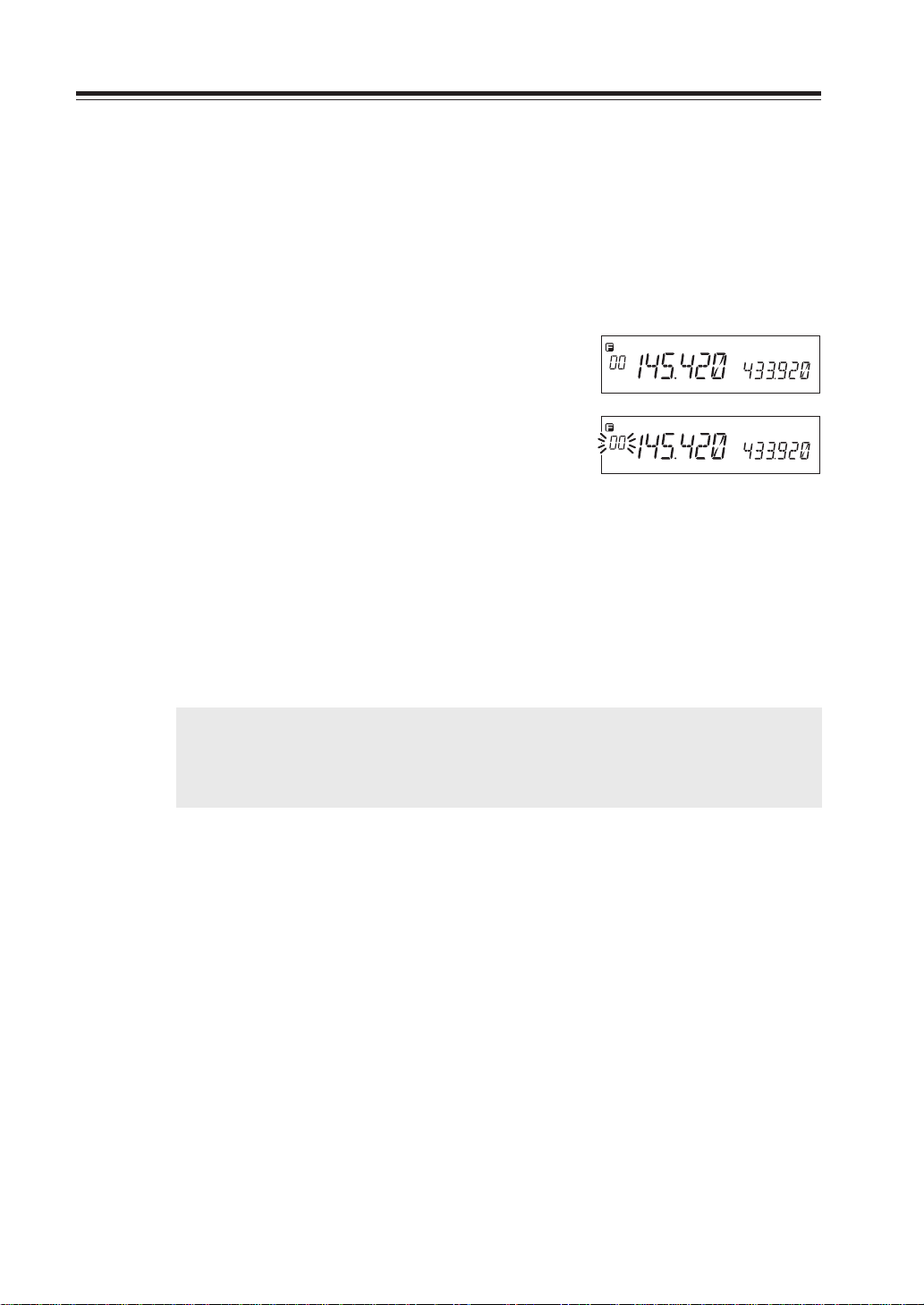
Recalling a memory channel
Basic Operations
1. Select the memory mode by pressing V/M key.
[00] appears on the display to indicate that the
unit is in the memory mode.
Repeat to switch the mode between memory
and VFO.
2. Select a memory channel.
Rotating the main dial (pressing UP/DOWN
key) will increase or decrease a memory channel number by 1 channel step. For recalling a
memory on the SUB band, first switch the
MAIN band by the B AND ke y. When the SUB
side is in the memory mode or CALL mode,
[ ] appears on the display.
When recalling any memory number between
100 and 139, the display on the SUB side will
disappear.
IMPORTANT: If memory channels have not been programmed, the unit will not be
switched to the memory mode by pressing V/M key. Please read memory
channel programming on the next page.
Memory channel
Memory mode
In case the SUB side is in the memory mode
19
Page 22
Basic Operations
How to program memory
1. Select a frequency to be programmed in the
VFO mode and set the parameters as appropriate. Refer the next page for programmable parameters.
2. By pressing FUNC key, [F] and [Memory No.]
icons will appear on the display.
3. Rotate the main dial (or press UP/DOWN key)
to select the desired memory channel number.
4. An empty channel is shown with a flashing
[Memory No.] icon.
5. By pressing V/M key while FUNC is on the
display, programming will be completed with
a beep sound.
6. If a previously programmed channel is selected
in the step 3, the memory channel will be overwritten by the step 5.
7. When CH-C is selected, CALL channel will
also be rewritten.
IMPORTANT: • Program the Theft-Alarm data in CH99.
• For Channels from 100 to 139, VHF/UHF band can be programmed indiscrimi-
nately. (VHF/UHF mixed scanning is possible by the memory program scan-
ning.)
During the unregistered channel
20
Page 23

Memory channel deleting
1. Select the memory mode by pressing V/M key.
Basic Operations
2. Select the desired memory channel number by
rotating the main dial.
Memory Mode
3. The programmed memory channel has the
memory number illuminated on the display.
4. By pressing M/W key together with FUNC key
while [F] icon is on, a beep will sound and the
memory will be deleted. At the same time,
[Memory No.] icon will start flashing.
NOTE: When a LCD memory channel is flashing, the full contents of the memory are
displayed in the LCD.
After pressing FUNC key again, if you press M/W key while [F] icon is on, you can
restore a deleted memory. However, after changing CH or the mode, restoration
will not be possible.
Programmable data in the memory channel
Memory channel including 00 – 99, 100 – 39, CALL channel and AL channel can store follo wing:
• Frequency
• Shift frequency
• Shift direction (+ / -)
• Tone encoder frequency
• Tone decoder frequency
• Tone encoder/decoder setting
• DCS encoder code
• DCS decoder code
• DCS setting
• Skip CH setting
• Busy channel Lock Out (BCLO)
• Digital mode setting
• Digital code
• Narrow mode setting
• AM mode setting
IMPORTANT: In PL/PH/AH, only frequency can be programmed.
21
Page 24
Basic Operations
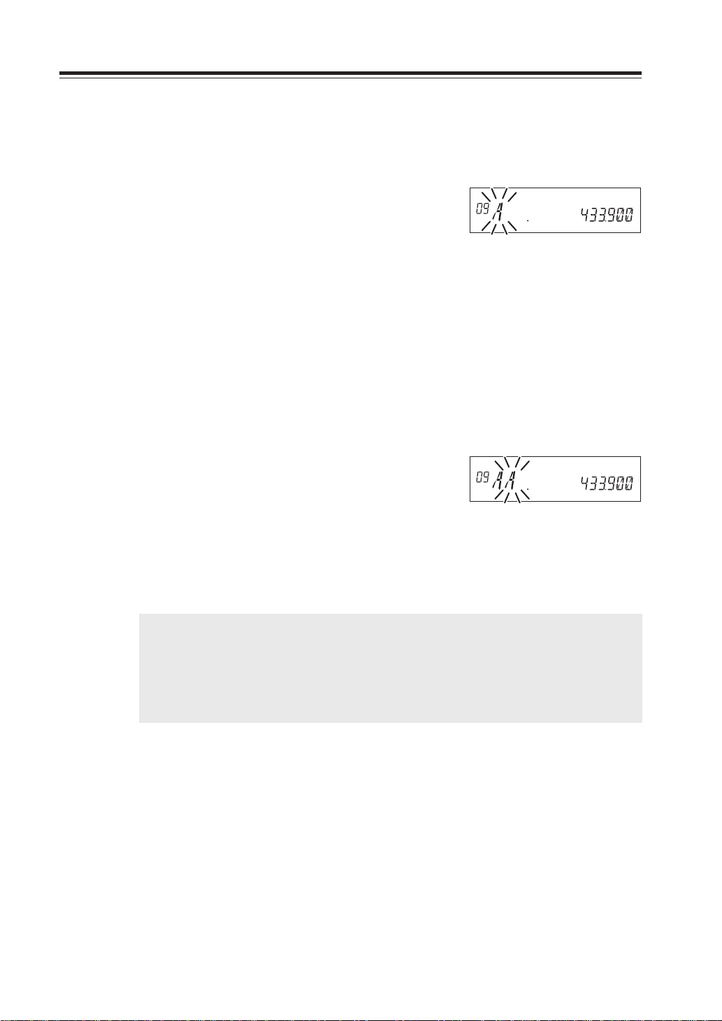
Channel name (Alphanumeric) registration function
The memory channels stored in the memory mode can be displayed with an alphanumeric tag
instead of the default frequency display. There are 67 characters available including A-Z, 0-9.
1. In the memory mode, select a channel to be
programmed.
2. Press the H/L key together with the FUNC key.
3. The display shows [A ] flashing.
4. Rotate the dial to select a character to be pro-
grammed.
5. By pressing the BAND key, the character is il-
luminated and entered.
An identical character to the one just entered
flashes on the immediate right ready to be edited.
6. Enter with the BAND key. (Repeat the same
sequence)
7. Pressing the CALL key during programming
will delete all characters to be programmed.
8. Pressing any key other than the BAND key and
the CALL key will complete the setting and the
display will return to the original status.
NOTE: In the memory mode, a designated alphanumeric tag is displayed instead of the frequency
for a channel with a designated channel name (CH number is displayed unchanged). By
pressing the FUNC key for 5 seconds, the frequency will be displayed.
(By pressing any key during operation, the display will return to show a channel name. But
by operating a key designated for some FUNC key, the unit will enter the designated
setting mode.)
22
Page 25
CALL mode
This is a memory mode that allows the transceiver to quickly recall the assigned memory channel
by simply pressing the CALL key, regardless of the current status of the unit.
The default setting is 145.00MHz/433.00MHz, and available 1ch each on VHF and UHF band.
To recall a CALL channel
Select the desired VHF or UHF band by pressing BAND key.
1. Press CALL key. The C icon appears on the
display and the transceiver enters the CALL
mode. In this mode, the main dial or the UP/
DOWN keys cannot change the frequency or
memory channels.
2. Press CALL key again or press V/M key to exit
CALL mode.
3. No scan functions are available in CALL mode.
To store a desired setting in the CALL channel, follow the memory mode programming instructions and assign your selected settings to memory channel C. The call channel can be modified but
cannot be eliminated or hidden.
Basic Operations
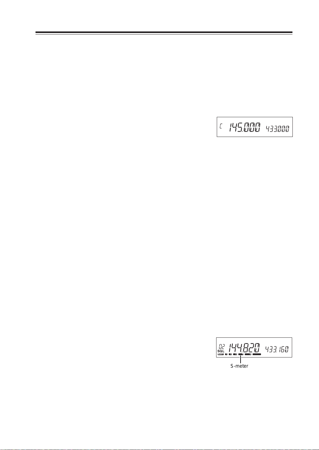
To receive signals
1. Be sure to have the unit connected to the ap-
propriate antenna, powered on, set the audio
volume and squelch level properly on both
MAIN and SUB bands.
2. Select the desired band by pressing BAND key
and browse frequencies or select desired frequency to listen to ongoing communications.
The S-meter shows relative signal strength
when the transceiver detects an incoming signal, and RX display lamp (green) turns on.
3. If the S-meter indicates an incoming signal but
nothing is heard from a speaker, check audio
level, squelch level, and CTCSS/DCS decoding status, which are explained elsewhere in this
manual.
SQL
BUSY 1 3 5 7 9
S-meter
23
Page 26

Basic Operations
Monitor function
A Monitor function is av ailable to receiv e weaker signals. Press
and hold SQL key for more than 1 second. Regardless of the
level setting of the squelch, it will be opened and the Busy
icon/RX lamp turn on the display. Press any key on the front
panel to exit.
IMPORTANT: Monitor function only operates on the MAIN band. Monitor function op-
erates irrespective of Tone squelch/DCS function setting.
Reverse function
This function is for monitoring the transmission frequency
instead of receiving frequency in repeater operation. This technique is commonly used to check if it is possible to communicate without using a repeater by monitoring the accessing,
station’s signal strength.
BUSY
When -5.000MHz SHIFT is set
1. Keep pressing the SQL key for more than 1 sec-
ond while SHIFT is set.
[R] icon illuminates on the display to indicate
that the reverse function is activated and the
squelch opens.
2. Pressing any key will cancel the operation.
R
BUSY
24
Page 27

To transmit
N
T
VHF/UHF TWINBAND FMTRANSCEVER
1. Set the transmission band to the MAIN side.
2. Be sure that you are authorized to operate on
the selected frequency. Check the system and
monitor the frequency to make sure that you
are not going to disturb any ongoing communications.
3. Press the PTT key on the microphone.
TX display lamp (red) illuminates to show the
unit is transmitting.
4. Speak into the microphone in a normal tone
while keeping the PTT key pressed.
Hold the microphone approximately 5cm away
from your mouth. Keeping this distance too
close or speaking too loud may result in poor
audio.
TX display lamp
MW
V/M
MAIN
TX/RX
MAIN
VOL
VV/UU
BAND
VHF/UHF TWINBAND FMTRANSCEVER
RX BAND SHIFT LOCK
CALL MHz
Basic Operations
DR-620
PACKET DIGITAL
TS/DCS
H/L SQL FU
SE
5. Releasing the PTT key will complete the trans-
mission and the unit will be back for receiving.
NOTE: Pressing the DOWN key together with the PTT key will transmit the CALL tone
signal. DR-620E will transmit the Tone Burst signal. See page 39 for details.
IMPORTANT: If you press the PTT key out of the transmission frequency range, [OFF]
icon will appear on the display. Transmission is not possible in this while.
Switching the transmission power
1. Press the H/L key. The transmission power
switches from Hi to Mid, Mid to Lo and then
Lo to Hi.
At MID power, [Mi] icon, and at LOW power,
[Lo] icon illuminates. Nothing appears on the
display at Hi power. The default is HI power.
RF meter shows •• when transmitting at LOW
power, •••• at MID power and •••••• at HI
power.
Transmission
power
HI
MID
LOW
620T/E
VHF UHF
50W 35W
10W 10W
5W 5W
Lo
1 35 7 9
At LOW power
Mi
1 3 5 79
At MID power
1 3 5 7 9
At HI power
IMPORTANT: The output power level cannot be changed during transmission.
25
Page 28

Parameter Setting Mode
IMPORTANT: Please read the following pages thoroughly prior to the change of any parameters.
THE PARAMETERS CANNOT BE SET WITHOUT ENTERING THE SET MODE.
By entering the Parameter Setting mode, some of the radio’s operating parameters can be changed
to suit your application. The following is the Selectable Parameters’ Menu.
NOTE: The Alphanumeric Channel Tag setting will not appear in the menu until memories have been programmed
first!
A list of the setting mode
Cut and keep the following list of the setting mode for your convenience.
Parameters Setting Mode
Default display
STEP 20
TIMER
BEEP 2
TOT OFF
TOTP OFF
APO OFF
ALERT
CKSFT OFF
BELL OFF
BCLO OFF
SCR OFF
COLOR 1 Illumination color switching
LAMP 4
C
HB 1200
BCON 0
Function
Channel Step setting
Scan type switching
Beep sound ON/OFF
Time-Out-Timer ON/OFF
TOT penalty ON/OFF
Auto-Power-Off ON/OFF
Tone Burst frequency setting*
Clock Shift setting
Bell function setting
Busy-Channel-Lock-Out setting
Theft Alarm ON/OFF
Dimmer setting
Call sign setting (packet)
Transmission speed setting (packet)
Beacon interval setting (packet)
Press the FUNC key /UP key
Press the SQL/DOWN key
*DR-620E has TB1750 Tone burst frequency as the default.
26
Page 29

To use the parameter setting mode
1. Press the FUNC key for more than 2 seconds to
enter the parameter Setting mode.
Parameter Setting Mode
2. Select a menu by pressing the FUNC key and
the SQL key, or UP/DOWN keys on the microphone.
3. Rotate the main dial to change the setting.
4. Pressing the FUNC/SQL and UP/DOWN key
will complete the setting and enters to the next
menu.
5. Pressing any key other than the FUNC/SQL and
UP/DOWN key will complete the setting and
exits the parameter setting mode.
At default display
27
Page 30

Parameter Setting Mode
TIMER BUSY
Channel Step setting
This is to select the channel step to be used in the VFO mode.
Refer to the chart below for the relation of the actual step
frequency and how it is displayed.
(Refer page 27 for how to enter the setting mode.)
STEP 5
(5 kHz)
STEP 100
(100 kHz)
NOTE: The default is as follows.
• DR-620E [STEP 12.5]
• DR-620T [STEP 5]
STEP 8.33
(8.33 kHz)
STEP 50
(50 kHz)
STEP 10
(10 kHz)
STEP 30
(30 kHz)
Scan Type
This is to select the scan resume condition. TIMER setting
allows the radio to resume scanning after 5 seconds, regardless of the signal receiving status. BUSY setting resumes scanning when the received signal is gone. The scan mode is explained later.
Beep Sound
This is to change the volume of a beep sound during operation.
1. [BEEP2] icon appears on the display.
STEP 12.5
(12.5 kHz)
STEP 25
(25 kHz)
STEP 15
(15 kHz)
STEP 20
(20 kHz)
28
2. By rotating the dial, the display will change as
below and the volume of a beep sound will be
changed.
Volume low
BEEP 1 BEEP 2
Volume High
BEEP 3
Volume 0
BEEP OFF
 Loading...