

Page 1

UHF FM MOBILE TRANSCEIVER
User Manual
Model name:DR-438
Brand name:plum
FCC ID:PH3-DR438H
IC:3070C-DR438H
1
Page 2

ALINCO, INC.
Y
odoyabashi Dai-bldg 13F
4-4-9 Koraibashi, Chuo-ku, Osaka 541-0043 Japan
Phone: +81-6-7636-2362 Fax: +81-6-6208-3802
http://www.alinco.com
E-mail:export@alinco.co.jp
UHF FM Transceiver / 400.000-489.995MHz
All EU and EFTA member states. Operator
license is required.
A1.0-13/05
Copyright Alinco, lnc. PS0665/FNEG-NE
Printed in China
Page 3
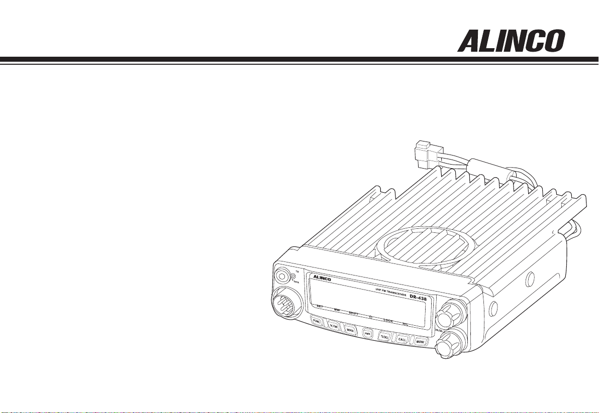
UHF FM Mobile Transceiver
DR-438
Instruction Manual
Thank you for purchasing your new Alinco transceiver.
Please read this manual carefully before using the
product to ensure full performance, and keep this
manual for future reference as it contains information
on after-sales services. In case addendum or errata
sheets are included with this product, please read
those materials and keep them together with this
instruction manual for future reference.
NOTE: DR-438 may be delivered to you after dealer-programming.
In such cases, please ask your dealer about the available
features in your unit and how to operate this unit.
Page 4
Introduction
Thank you very much for purchasing this excellent Alinco transceiver.
Our products are ranked among the finest in the world. This radio has
been manufactured with state of the art technology and it has been tested
carefully at our factory. It is designed to operate to your satisfaction for
many years under normal use.
Ple ase read thi s manual completely from the first page to the
last, to learn all the functions the product offers. It is important to
note that some of the operations may be explained in relation to
information in previous chapters. By reading just one part of the
manual, you may risk not understanding the complete explanation
of the function.
Before transmitting
There are many radio stations operating in proximity to the frequency
ranges this product covers. Be careful not to cause interference when
transmitting around such radio stations.
■
Lightning
Please note that no car provides adequate protection of its passengers
or drivers against lightning. Therefore, Alinco will not take responsibility
for any danger associated with using its radios or inside the car during
lightning.
■
For North American users
Due to strict rules, this product is blocked for operations before sales
and only dealers can program the radio before delivery to consumers.
Manufacturer is n ot aware of details of such dealer-pr og ra mm in g
therefore please kindly contact your dealer rst in case technical-service
may be necessary.
Features
■ Output power selectable 40W
■ PC-programmable
■ Alphanumeric name tags
■ Voice Compander (Reduce Noise & enhance audio
clarity)
■ Optional Inversion Scramble (DR-135S only)
■ Sub-tone (CTCSS/DCS) Encode/ Decode, DTMF/ANI
2-tone and 5-tone
,
■ Various scan modes, Key lock, Narrow operations
and more at NO extra costs.
Conformity Symbols
Tested to comply MIL-STD-810G
-Shock: Method 514.6/I,IV -Vibration: Method 516.6/I
Conformity Information
In case the unit you have purchased is marked with a CE symbol,a copy
of relative conformity certicate or docu-ment can be reviewed at http://
www.alinco.com/usa.html.Please see the back-cover for more details.
Copyright 2012 All rights reserved. NO part of this document may be
reproduced, copied, translated or transcribed in any form or by any
means without the prior writhout the prior written permission of Alinco.
Inc,Osaka, Japan, English Edition Printed in China.
Page 5

SAFETY TRAINING
WARNING:
This radio generates RF electromagnetic energy during transmission.
This radio is designed for and classified as “Occupational Use Only”,
meaning it must be used only during the course of employment by
indiv iduals aw are of th e hazards, and the w ays to mi nimize su ch
hazards.This radio is NOT intended for use by the “GeneralPopulation”
in an uncontrolled environment.
• Fo r c omp lia nce wit h F CC and Ind ust ry Can ada RF Exp osu re
Requirements, the transmitter antenna installation shall comply with
the following two conditions:
1.The transmitter antenna gain shall not exceed 0 dBi.
2.The antenna is required to be located outside of a vehicle and kept at
a distance of 63 centimeters or more between the transmitting
antenna of this device and any persons during operation.For small
vehicle as worst case, the antenna shall be located on the roof top at
any place on the centre line along the vehicle in order to achieve 63
centimeters separation distance. In order to ensure this distance is met,
the installation of the antenna must be mounted at least 63 centimeters
away from the nearest edge of the vehicle in order to protect against
exposure to bystanders.
CAUTION:
To ensure that your exposure to RF electromagnetic energy is within
the FCC allowable limits for occupational use, always adhere to the
following guidelines:
DO NOT operate the radio without a proper antenna attached, as this
•
may damage the radio and may also cause you to exceed FCC RF
exposure limits. A proper antenna is the antenna supplied with this
INFORMATION
radio by the manufacturer or an antenna specically authorized by the
manufacturer for use with this radio.
DO NOT transmit for more than 50% during the time of employment
•
(50% duty cycle or less). Transmitting excessive amount of time can
cause RF exposure compliance requirements to be exceeded. Please
carefully read this instruction manual to learn how to transmit and stop
transmitting before starting to use it.
Electromagnetic Interference/Compatibility
Du ring tra nsm iss ion s, your rad io gen erate s R F e nergy that can
possibly cause interference with other devices or systems. To avoid
such interference, turn off the radio in areas where signs are posted to
do so. DO NOT operate the transmitter in areas that are sensitive to
electromagnetic radiation such as hospitals, aircraft, and blasting sites.
Occupational/Controlled Use
This product is used in situations that users are exposed to RF as
consequence of their employment provided those users are fully aware
of the potential RF hazards and can exercise control over their exposure.
This transceiver is NOT ATEX approved and NOT intended for the use
•
in hazardous explosive atmospheres.
Page 6
FOR CLASS B UNINTENTIONAL RADIATORS:
This equipment has been tested and found to comply with the limits for a
Class B digital device, pursuant to part 15 of the FCC Rules.
These limits are designed to provide reasonable protection against
harmful interference in a residential installation.
This equipment generates, uses and can radiate radio frequency energy
and, if not installed and used in accordance with the instructions, may
cause harmful interference to radio communications. However, there is
no guarantee that interference will not occur in a particular installation.
If this equipment does cause harmful interference to radio or television
reception, which can be determined by turning the equipment off and on,
the user is encouraged to try to correct the interference by one or more
of the following measures:
●
Reorient or relocate the receiving antenna.
Increase the separation between the equipment and receiver. ●
Connect the equipment into an outlet on a circuit different from that to ●
which the receiver is connected.
Consult the dealer or an experienced radio/TV technician for help.
●
FOR CUSTOMERS IN CANADA :
Le présent appareil est conforme aux CNR d'Industrie Canada applicables
aux appareils radio exempts de licence.
L'ExPLOITATION EST AUTORISéE AUx DEUx CONDITIONS SUIVANTES :
(1) l'appareil ne doit pas produire de brouillage, et
(2) l'utilisateur de l'appareil doit accepter tout brouillage radioélectrique
subi, même si le brouillage est susceptible d'en compromettre le
fonctionnement.
PRECAUTIONS:
The manufacturer declines any responsibilities against loss of life and
property due to a failure of this product when used with or as a part of a
device made by third parties.
Use of third party accessory may result in damage to this product. It will void
our warranty for repair.
Handling this product
Be sure to reduce the audi o output level to minimum before using an
earphone or a headset. Excessive audio may damage hearing.
Do not ope n the uni t wit hou t p erm i ss i on or i nst ruc t io n fro m t he
manufacturer. Unauthorized modification or repair may result in electric
shock, re and/or malfunction and voids warranty.
Do not operate this product in a wet place such as in a shower room. It
may result in electric shock, re and/or malfunction.
Do not place the product in a container carrying conductive materials,
such as water or metal in close proximity. A short-circuit to the product may
result in electric shock, re and/or malfunction.
In case of emergency
In case of the following situation(s), please turn off the product, switch
off the source of power, then remove or unplug the power-cord. Please
contact your local dealer of this product for service and assistance.
Do not use the product until the trouble is resolved. Do not try to
troubleshoot the problem by yourself.
When a strange sound, smoke and/or strange odor comes out ●
of the product.
When the product is dropped or the case is broken or cracked. ●
When a liquid penetrated inside. ●
Whe n a power co rd (includin g DC cables, AC cables and ●
adapters) is damaged
For your safety, turn off then remove all related AC lines to the product and
its accessories from the wall outlet if a thunderstorm is likely.
Maintenance
Do not open the unit and its accessories. Please consult with your local
dealer of this product for service and assistance
Page 7
Environment and condition of use
It is recommended that you check local trafc regulations regarding the use of
a radio equipment while driving. Some countries prohibit or apply restrictions
for the operation of radios and mobile- phones while driving.
Do not use this produ ct in clo se proxi mit y to other el ect ronic de vic es,
especially medical ones. It may cause interference to those devices.
Keep the radio out of the reach of children. This product is not a toy and
contains small part that may be dangerous when swallowed.
In case a liquid leaks from the product, do not touch it. It may damage your
skin. Rinse with plenty of cold water if the liquid contacted your skin.
Never operate this product in facilities where radio products are prohibited for
use such as aboard aircraft, in airports, in ports, within or near the operating
area of business wireless stations or their relay stations.
Use of this product may be prohibited or illegal outside of your country. Be
informed in advance when you travel.
The manufacturer declines any responsibilities against loss of life and/or a
property due to a failure of this product.
Do not use multiple radios in very close proximity. It may cause interference
and/or damage to the product(s).
Environment and condition of use
Do not use the prod uct in pr oximi ty to a TV or a ra dio. It may cause
interference or receive interference.
Do not install in a humid, dusty or insufciently ventilated place. It may result
in electric shock, re and/or malfunction.
Do not install in an unstable or vibrating position. It may result in electric
shock, re and/or malfunction when/if the product falls to the ground.
Do not install the product in proximity to a source of heat and humidity such
as a heater or a stove. Avoid placing the unit in direct sunlight.
Be cautious of a dew formation. Please completely dry the product before
use when it happens.
About transceiver
Do not connect devices other than specied ones to the jacks and ports on
the product. It may result in damage to the devices.
Turn off and remove the power source (AC cable, DC cable, battery, cigar
cable, charger adapter etc.) from the product when the product is not in use
for extended period of time or in case of maintenance.
Use a clean, dry cloth to wipe off dirt and condensation from the surface of
the product. Never use thinner or benzene for cleaning.
Check with your local waste ofcials for details on recycling or proper
disposal in your area.
PC PROGRAMMING
NOTE: The utility software may be availa ble to distributors/deal ers only. USB
programming cable is required. The manufacturer will not release the software to
unauthorized party so please contact your dealer for details.
Page 8

CONTENTS
Supplied Accessories/Optional Accessories .....................1
Supplied Accessories ....................................................................... 1
Initial Installation ..................................................................2
Mobile installation ............................................................................2
DC Power Cable Connection ...........................................................3
Power supply voltage Display ..........................................................5
Antenna Connection ........................................................................5
Accessories Connections ................................................................. 5
Getting Acquainted ..............................................................7
Front panel ....................................................................................... 7
Rear panel .......................................................................................8
Display .............................................................................................8
Microphone .....................................................................................9
Operating Mode
Basic Operations .................................................................11
Switching the Power On/Off
Adjusting the Volume ...................................................................... 11
Switch between VFO and Channel mode ....................................... 11
Adjusting Frequency/Channel Through Selector Knob .................... 11
Adiusting squelch level ....................................................................11
Receiving .........................................................................................11
Transmitting .....................................................................................11
Transmitting Tone Burst Tone .......................................................... 12
Transmitting Optional Signaling ....................................................... 12
Memory Channel Programming ....................................................... 12
........................................................................10
............................................................11
Memory Channel DeletIng
...............................................................12
KEY OPERATIONS ................................................................13
Squelch Off/Squelch Off Momentarry ..............................................13
Frequency/Memory Scan ................................................................. 13
Memory Scan ...................................................................................13
CTCSS/DCS Encode and Decode setup ......................................... 13
CTCSS SCAN ..................................................................................14
DCS SCAN ......................................................................................14
High/Mid/Low Power switch ............................................................. 14
Compander ......................................................................................14
Offset Direction and offset frequency setup ..................................... 14
Keypad Lockout ...............................................................................15
Auto-Dialer Setup
Transmitting Edited DTMF Tones in the Auto-dialer Memory ...........15
............................................................................. 15
PARAMETER SETTING MODE .............................................16
Frequency Channel Step Setup ....................................................... 16
DTMF, DTMF ANI, 2Tone or 5Tone Signaling ..................................16
Sending 2-Tone Call .........................................................................17
Sending 5-Tone Call .........................................................................17
Sending DTMF call ..........................................................................17
Signaling Combination setup ...........................................................17
High/Mid/Low Power Selection ........................................................18
Band-width Selection .......................................................................18
TX OFF Setup .................................................................................. 18
Busy Channel Lockout ..................................................................... 19
Page 9

CONTENTS
Editing Channel NAME ...................................................................19
Reverse TX/RX ................................................................................ 19
Talk Around .....................................................................................19
Voice Compander ...........................................................................20
Scrambler setup (Encryption) ..........................................................20
Radio's DTMF Self ID Enquiry ......................................................... 20
Radio's 5TONE Self ID Enquiry ....................................................... 20
Beep Sound .....................................................................................21
TOT (Time-out timer) .......................................................................21
APO (Auto power off) ....................................................................... 21
DTMF Transmitting Time
Display Iiiumination Color Setting ....................................................22
Scan Resume Time Setup ............................................................... 22
LCD Dimmer ....................................................................................22
Tone-burst Tones .............................................................................22
Display Mode Setup ......................................................................... 22
PIN Setup(
Address list .....................................................................................23
RESET (
Useless if PIN is not assigned
May be blocked for dealer-programmed units
Microphone Operation ......................................................... 24
Keypad Lock ....................................................................................24
Transmitting DTMF By Microphone Keypad .................................... 24
Function Setup By Microphone Keypad ........................................... 24
Switches between VFO and channel mode .................................... 24
Short Calling CALL Channel ........................................................... 24
.................................................................. 21
) ................................. 23
) ......... 23
Transmitting DTMF Code ................................................................. 24
Frequency Step ............................................................................... 24
Optional signaling ...........................................................................24
Scan Skip ........................................................................................ 25
Frequency/Channel scan ................................................................ 25
Busy Channel Lockout ..................................................................... 25
Reverse TX/RX ................................................................................ 25
TOT (Time-out timer) .......................................................................25
CTCSS/DCS Encode and Decode ................................................... 25
Talk Around .....................................................................................26
Beep Sound .....................................................................................28
HIGH/MID/LOW Power Selection ....................................................28
LCD Backlight
................................................................................26
Anti-theft Alarm ...................................................................27
Cable Clone ........................................................................... 27
Maintenance .......................................................................... 27
Default Setting after Resetting(UHF) ...............................................31
Trouble Shooting .............................................................................. 31
Specications ....................................................................... 30
Appendix ............................................................................... 31
50 groups CTCSS Tone Frequency(Hz). .........................................31
1024 groups DCS Code. .................................................................. 31
Page 10
1
Supplied Accessories
Supplied Accessories
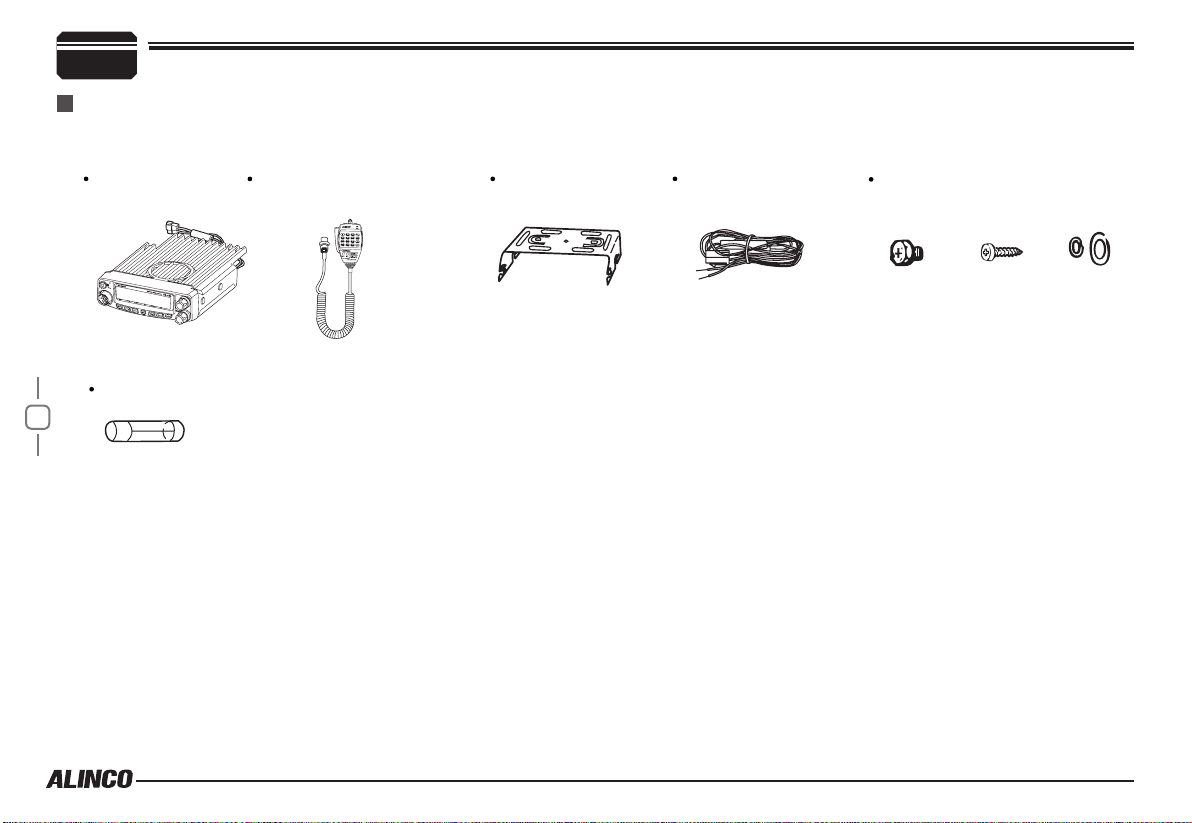
Carefully unpack to make sure the following items are found in the package in addition to this manual:
Transceiver
DR-438
Microphone EMS-74
(with DTMF keyboard)
Mo b i le Mo unti n g
Bracket
DC Power Cable with
Fuse Holder
Spare Fuses
1
The standard accessories may vary slightly depending on the version you have purchased. Please contact
your local authorized Alinco dealer should you have any questions. Alinco and authorized dealers are not
responsible for any typographical errors there may be in this manual. Standard accessories may change
without notice.
Warranty Policy: Please refer to any enclosed warranty information or contact your authorized Alinco dealer /
distributor for the warranty policy.
■
In order to operate this product, a properly tuned antenna, its feedline with connectors and
xing hardware are necessary. Please consult with your dealer for details.
Hardware Kit for Bracket
Black screws
(
M4X8mm
4PCS
Tapping screws
)
(
M5X8mm
4PCS
)
S-Washer
Page 11
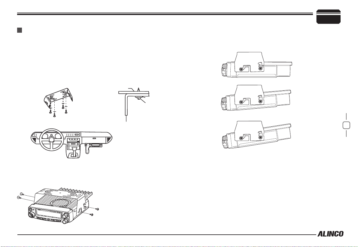
Mobile installation
The transceiver may be installed in any position in your car, where the
controls and microphone are easily accessible and it does not interfere
with the safe operation of the vehicle. If your vehicle is equipped with
air bags, be certain your radio will not interfere with their deployment. If
you are uncertain about where to mount the unit, contact your vehicle's
dealer.
Install the mounting bracket in the vehicle using the supplied self-
1.
tapping screws (4pcs) and at washers (4pcs).
Car body
Washer (M5)
Tapping screw
(M5x20mm)
Initial Installation
Determine the appropriate angle of the transceiver, using the 3 screw
hole positions on the side of the mounting bracket.
2
Mounting bracket
Position the transcei ver, t hen inser t and tig hten the supplied
2.
hexagon SEMS screws.
Double check that all screws are tightened to prevent vehicle
vibration from loosening the bracket or transceiver.
Caution:
Use only the provided screws
otherwise you risk damaging the
circuit board, components or fall-off
of the unit.
2
Page 12
2
Initial Installation
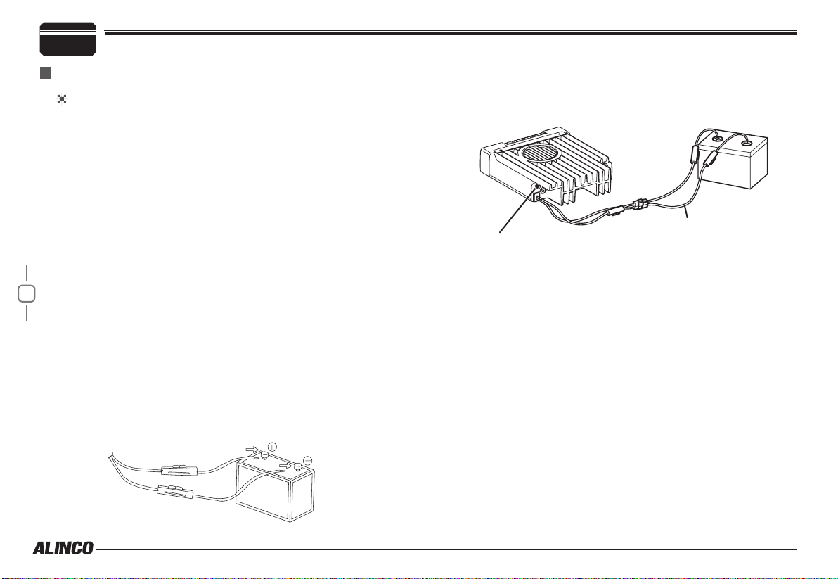
DC Power Cable Connection
Mobile Operation
The v ehicle batter y must have a nominal ra ting of 12V. Never
connect the transceiver to a 24V battery. Be sure to use a 12V
vehicle battery that has sufficient current capacity. If the current
to the transceiver is insufficient, the display may darken during
transmission, or transmitting output power may drop excessively.
Route the DC power cable supplied with the transceiver directly
1.
to the vehicle's battery terminals using the shortest path from the
transceiver.
Never use the cigarette lighter socket as a DC source.
The entire length of the cable must be dressed so it is isolated from
heat, moisture, and the engine secondary (high voltage) ignition
system/ cables.
After installing cable, in order to avoid the risk of damp, please
2.
3
use heat-resistant tap to tie together with fuse box. Don't forget to
reinforce whole cable.
In or der to av oid th e r isk of sh ort ci rcu it, pl eas e c ut dow n
3.
connection with negative (-) of battery, then connect with radio.
Confirm the correct polarity of the connections, then attach the
4.
power cable to the battery terminals; red connects to the positive (+)
terminal and black connects to the negative (-) terminal.
Never remove the fuse holders from the cable.
Reconnect any wiring removed from the negative terminal.
5.
Red
Black
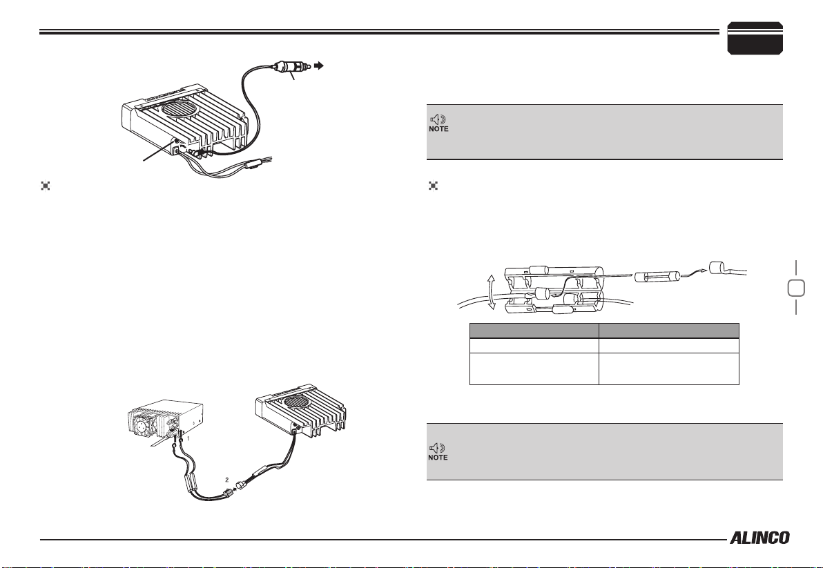
Connect the DC power cable to the transceiver's power supply
6.
connector.
If the ignition-key on/off feature is desired(optional feature),use the
optional EDC-43(For Cigar-Plug connection) cable. Connect one of the
cables between the ACC terminal or a Cigar-Plug that operates with
the vehicle ignition or ACC switch on the vehicle and EXT POWER
jack on the rear side of the unit.
When the ignition key is turned to ACC or ON(Start) position with
7.
the radio turned off, the power switch illuminates. The illumination
will be turned off when the ignition key is turned to the off position.
To turn on the unit, press the power switch manually while it is
illuminated. (While ignition key is at ACC or ON position)
When the ignition key is turned to ACC or ON position with the
8.
radio's power switch on, the unit turns on automatically and the
power switch will be lit. Turn the ignition key to OFF position or
manually turn the power switch off to shut down the radio.
Use of ignition-key ON/OFF feature drains 5mAh of current from
9.
the battery as long as the EDC-43 is being connected.
the connectors rmly together until the locking tab clicks.
Press
DC power cable
Ext. Power jack
Page 13
ACC terminal
Cigar-Plug connection
Optional EDC-43 required
Ext. Power jack
Fixed Station Operation
In order to use this transceiver for xed station operation, you will need
a separate 13.8V DC power supply (not included) , Please contact local
dealer to require.
The current capacity of your power supply must be 12A or more.
Connect the DC power cable to the regulated DC power supply
1.
and ensure that the polarities are correct. (Red: positive, Black:
negative).
Never directly connect the transceiver to an AC outlet.
Use the supplied DC power cable to connect the transceiver to a
regulated power supply.
Do not substitute a cable with smaller gauge wires.
Regulated
power supply
Black
Red
Initial Installation
Connect the transceiver's DC power connector to the connector
2.
the DC power cable.
Press the connectors rmly together until the locking tab clicks
Before connecting the DC power to the transceiver, be sure to switch
the transceiver and the DC power supply OFF.
Do not plug the DC power supply into an AC outlet until you make all
connections.
2
REPLACING FUSES
If the fuse blows, determine the cause, then correct the problem.
After the problem is resolved, replace the fuse. If newly installed fuses
continue to blow, disconnect the power cable and contact your dealer
for assistance
Only use fuses of the sp ecified type an d rating, otherwi se the
transceiver could be damaged.
If you use the transceiver for a long period when th e vehicle battery is
not fully charged, or when the engine is OFF, the battery may become
discharged, and will not have sufcient reserves to start the vehicle. Avoid
using the transceiver in these conditions.
.
Fuse Location Fuse Current Rating
Transceiver 15A
Supplied Accessory DC
power cable
20A
on
4
DC power cable with fuse holder
Page 14

2
Initial Installation
Power supply voltage Display
After connecting the transceiver to the power supply, the supply voltage
can be displayed on LCD by pressing the
key.
The display immediately changes as the voltage supply changes, It also
displays voltage during transmission.
The transceiver will return to its normal operation when the power is
turned ON/OFF or repeat above operation.
The rang e of disp la yed volt ag e is from 7V to16 V DC. Be ca us e the
displayed value is estimated, please use a voltmeter when a more precise
Important
5
reading is desired.
key together with the
Antenna Connection
Before operating, install an efficient, well-tuned antenna. The success
of your installation will depend on the type of antenna and its correct
installation.
Use a 50Ω impedance antenna and lo w-los s coaxial feed-line that
has a characteristic impedance of 50 Ω, to match the transceiver input
impedance. Coupling the antenna to the transceiver via feed-lines having
an impedance other than 50Ω reduces the efficiency of the antenna
system and can cause interference to nearby televisions, radio receivers
and other electronic equipment.
Transmitting without first connecting an antenna or other matched
load may damage the transceiver. Always connect the antenna to the
transceiver before transmitting.
All xed stations should be equipped with a lightning arrester to reduce
the risk of re, electric shock, and transceiver damage.
Accessories Connections
External Speaker
If you plan to use an external speaker, choose a speaker with an
impedance of 8 Ω. The external speaker jack accepts a 3.5 mm (1/8")
mono (2-conductor) plug.
External speaker adopt double port BTL, please care about the connection.
Do not use the speaker that requires grounding.
Error
Ground
Page 15

Microphone
For voice communications, connect a provided microphone into the
socket on the front of the main unit. Turn the ring firmly on the plug
until it locks. Attach the supplied microphone hanger in an appropriate
location using the screws included in the screw set.
Initial Installation
2
Micr ophone
connector
Microphone [EMS-74]
External speaker
Antenna
6
Page 16

Getting Acquainted
3
Front panel
Basic Functions
NO. KEY FUNCTION
1
7
PWR(Power) Power on/Off
2
VOL Adjust Volume Key
3
SQL Knob Adjust Squelch level
4
Main Dial
5
FUNC/SET Function Key
6
V/M/MW
7
MHz/SHIFT Step Size Key ( step:1MHz)
8
TS/DCS/LOCK Sets CTCSS and DCS value
9
CALL/H/L CALL Channel
10
MONI Squelch off
11
Data Terminal
12
TX lights during Transmitting
Change frequency, memory channel and scan
direction etc.
Switches between VFO mode and Channel
mode
Data reading/writing, cloning and theft alarm
functions
13
Mic.connector
Microphone connection port
Press key until icon appears then press the following
key.
NO. KEY FUNCTION
5
FUNC/SET Conrms the selective functions and exit
6
V/M/MW Stores data into channels
7
MHz/SHIFT Sets offset direction and offset frequency
8
TS/DCS/LOCK Sets Keypad lock function
9
10
MONI Compander mode on/off
Press
key and following key together to activate
following function:
NO. KEY FUNCTION
1
MONI+PWR Reset to factory default settings
6
V/M/MW Erase the memory
7
MHz/SHIFT
8
TS/DCS/LOCK Auto dialer
9
CALL
10
MONI Enters power supply voltage indication mode
Narrow band
Enters clone data function mode
Functions that require continuous pressing following key
to be activated
NO. KEY FUNCTION
5
FUNC/SET
10
MONI Monitor mode
Press and hold for 2s to enter the Setting
mode
Page 17

Rear panel
21
NO. KEY FUNCTION
Ex t . Po w er
1
Jack
Ext.Speaker
2
Terminal
Antenna
3
Connector
Terminal for connecting optional cable for use with
ignition key On/Off function.
Terminal for optional external speaker.
Connection for 50Ω coaxial cable and antenna.
Connector is PL/M.
DISPLAY
14
19
1
2
16
17
18
15
13
Getting Acquainted
NO. KEY
3
1
2
3
4
5
6
7
8
9
10
11
12
13
14
15
13
12
10
11
9
16
17
18
8
19
Å
SQL
M
Dot
Decimal point
DCS
A
Nar
LO
Mi
FUNCTION
(Not in use)
Memory mode.
Indicates the channel number in memory mode.
Channel skip.
Indicates the decimal point of frequency and the
scanning function.
Indicates the frequency or memory name.
Signal is being received or monitor.
Signal strength of receiving and transmitting.
Compander.
Keypad lock .
Set DCS function.
Set CTCSS function.
Offset frequency direction.
Scramble. (S-version only)
Auto power off.
Narrow mode.
Function key is activated
3
8
3
4
5
6
7
Page 18

Getting Acquainted
3
microphone
NO. KEY FUNCTION
UP Increase frequency ,channel number or setting value.
1
9
DOWN Decrease frequency, channel number or setting value.
2
PTT Push-To-Talk key to transmit.
3
Numerical Keyd Input VFO frequencies and other various oprations
4
DTMF ON/OFF Switches between DTMF and function operations.
5
LOCK Switch Locks all keys excep PTT.
6
MIC Microphone element is located.
7
MIC Connector Diagram(in the front view of connector)
Page 19

Operating Mode (VFO Mode or Channel Mode)
(
)
( )
)(
According to practical application,you can set the radio works as VFO
Transceiver mode or Channel mode.
1.
the programming software.
2.
A. Frequency + Memory mode: At this
mode, when set display as "FR", it
en ters int o Fr eque ncy + Me mory
mode. Once the radio is turned off or
switched to another channel, the temporary setting will be erased
and back to initial settings. (As pic 1)
B. Channel + Name Tag Mode: When
set display as "N M" , it e nt er s into
Channel +Name Tag Mode. At this
mode, it will display corresponding
cha n n e l name wh e n the c u r r e nt
channel is edited with name in advance. Otherwise, it will display
frequency and channel number. Its operations are the same as
frequency+channel mode. (As pic 2)
C. VF O M ode(F req uency mode ): This
mode sho ws on ly frequency on the
di s p l a y. Set mo de op e r a tion an d
Ch annel se tting are s tored as the
latest value. Once the radio is turned
off or changed to new frequency using VFO, the value remains
until next change. (As pic 3)
:Please refer to "Display Mode" in P.22.
See the Function Setup menu in
Pic 1
Pic 2
(Pic 3)
3.
When set display mode as "CH", it enters
into Commercial radio mode. At this mode,
ex cept ver y l i mit e d f eatu re, all oth e r
functions should be set by PC software in
advance to the operation. If name tag is
programmed, the LCD will display name
tag. (As pic 4) Once the transceiver has
been set as this mode, users can't access
to reset or changing masked parameters manually.
Some countries of distribution do not allow commercial users
to program the radio freely and/or to operate in frequnecydisplay(VFO) mode.
In ad di tion,the prog ra mming software is made available to
dealer s only and A linco r el eases t he softwa re only t o the
authorized importers.
Please consult with your dealer of purchase of this product in
case you may have questions about channel programming and
available features. Alinco and its authorized distributers are not
aware of details of such programming performed by your dealer.
(Pic 4)
Pic 5
4
10
Page 20

Basic Operations
5
The symbol stands for restricted or optional functions. Features and/
or operations may not be available to commercial-mode users unless
pre-programmed by the dealer.
Switching The Power On/Off
According to the option selected during
installation, press the switch or turn the
ignition key to ACC or ON position to power
on. Press the key for 1 seconds or turn the
ignition key to OFF position to turn off.
PWR KEY
be masked. In this status, turn Main Dial or Microphone [
/ ] key will increase or decrease frequency quickly by
1MHz step.
Under chann el mode, you can change the cur rent channel to
2.
the desired one through Main Dial, clockwise turn to the forward
channel, anticlockwise turn to the backward channel. In relative
Operating mode, Microphone's [
function for adjusting frequency and channel.
/ ] key has the same
Adjusting The Volume
Turn the VOL knob clockwise to increase the
audio level, counterclockwise to decrease.
11
Press and hold MONI key to hear a white-noise to set the proper audio level.
Switch between VFO and MEMORY mode
In standby, press key or Microphone's
key until appear , this indicates current
frequency in Memor y mode. Repeat above
operation to switch between Frequency mode
(VFO) and Memory mode.
Adjusting Frequency/Channel THROUGH the dial
Un d er freq uenc y (V FO) mode , y o u
1.
can change the current freq uency to
th e de s ired one thro ugh dial ; Turn
clockwise to increase frequency; turn
counterclockwise to decrease. Ever y
click will increase or decrease one step.
Press
key, the KHz order digits w ill
Dial
Frequency
decrease
Frequency
increase
ADJUSTING SQUELCH LEVEL
A squelch eliminates white-noise (the background noise when a signal is
not received). Higher level settings will keep the squelch "closed” more
tightly for quieter monitoring, but weak signals will not be heard. Lower
settings allow weaker signals to "open” the squelch but noise may also
cause it to open. By rotating the SQL knob, adjust the squelch level to
the desired level.
Receiving
Select the desired receiving frequency
or browse channels to listen to ongoing
communications. The S-meter shows relative
signal strength between BUSY and 5th segment when the transceiver
detects an incoming signal.
Transmitting
Press and hold key or press MIC's key to monitor for a while to
conrm the channel desired is not busy. Release
key to return standby status,Then press and hold [PTT] key to speak into
microphone.
or press Mic's
Page 21

Please hold the microphone approximately 2.5-5.0cm from your lips
then speak into the microphone in your normal speaking voice.
While transmitting, LED lights RED and TX-meter shows relative power level.
Release PTT to receive.
, and
Transmitting Tone BURST TONE
Press and hold [PTT] key, then press Microphone [ ] key to
transmit current selected tone-burst tone. Pre-programming is necessary.
Transmitting OPTIONAL SIGNALING
Press and hold [PTT] key, then press Microphone
key in front panel or press Mic's key to transmit pre-stored and
selected DTMF/2Tone/5Tone optional signaling. Pre-programming is
necessary.
key or press
Basic Operations
MEMORY CHANNEL PROGRAMMING
Under frequency mode (VFO), turn
1.
frequency or input frequency by MIC's numeric keys.
Press
2.
to select the desired signaling. See P.13 for details.
Press
3.
and current channel number,
ashing means current channel is empty.
Turn
4.
channel number to store.
Press
5.
number disappears and beep sounds
twice.
Press
6.
stored.
key to enter CTCSS/DCS signaling setup, turn Main Dial
key, LCD appears , icon
Main Dial to select the desired
key, , icon and channel
V/M key again to conrm that the memory channel is properly
Main Dial to select the desired
icon
MEMORY CHANNEL DELETING
Under Memory mode, turn
1.
deleted.
Press
2.
deleted beep sounds.
deleted.
key and key together, current memory will be
Main Dial to select cha nn el to be
icon ashing means current memory is
5
12
Page 22

KEY OPERATIONS
6
squelch off/squelch off momeNTARY
Squelch Off: Press
1.
to resume squelch. Thi s is set by programmi ng software as an
option.
Squelch Off Momentary: Press and hold
2.
release
The above functions can be set in by software only, not by key
operation.
key to disable squelch, press key again
key to disable squelch,
key to resume squelch.This is factory default operation.
Frequency/MEMORY Scan
Frequency Scan
Scans all VFO frequencies in regard to the preset tuning step.
13
In VFO mode, press
1.
start scanning.
Main Dial or press Microphone [ / ] key to
Turn
2.
change scan direction.
Press any key except
3.
for 1 second to
and key to stop.
MEMORY Scan(channel scan)
Scans all memory channels unless Memory skip feature is selected for a
given memory.
In memory mode, press
1.
scan
Turn selector knob or press Microphone
2.
[ / ] key to change scan
direction.
Press any key except
3.
key for 1 second to enter into channel
and key to exit.
CTCSS/DCS Encode and Decode setup
Many repeaters require a CTCSS tone or a DCS code encode
setting as a “key” to access the system, so-called “selective-calling”.
Sometimes, CTCSS or DCS decode features are used on the output of
a repeater so they can be used as a squelch. In this mode, regardless
of the main squelch status, the audio can be heard ONLY when the
matching tone/code signal is received. The combination of CTCSS
squelch and DCS function is not available; only one or the other may
be used for a given channel.The operation is available on VFO and
memory mode. Dealer-Preprogrammed units can't operate this function
manually. In the memory mode, the setting is temporary; changing the
channel or turning off the radio will erase the setting.
Press
key. The current setting will be displayed with T/SQ/
1.
DCS icons and relative frequency/code. Press the same key to
select T/SQ/DCS setting.
The numbers (such as 88.5) represent the CTCSS frequency in
2.
Hz. When it is displayed with the icon only, the unit transmits
the sub-audible tone while the PTT
is pressed (encode) and the repeater
access is en a b l e d (assuming th e
repeater is using 88.5Hz tone).
Press the same key again so that the
3.
i c on shows up on th e di s play.
This is the CTCSS decode frequency.
This enables CTCSS squelch (or Tone
Squelch, TSQ).
Press it again so that the 3-digit number
4.
and icon is displayed. This is the DCS code, and it enables
DCS encoding and decoding.
For 2-4, rotate the main dial or press the [
change tone or code. Press any key ( Except FUNC / PWR / TS / DCS,
/ ] keys to
Page 23

UP / DOWN keys) to enter the setting and return to original status. The
T/SQ/DCS icon will remain on the display to show the current selective-
calling status. To exit, simply use the TS/DCS key and press it until the
relative status icon T/TQ/DCS disappears.
The CTCSS encoding and decoding frequencies may be set differently.
The encode settin g frequency automatically relates to the dec ode
setting, but decode setting does not affect encode. The standard set of
50 different CTCSS tones are available. DCS encode/decode cannot be
separated. The list of selectable tones and codes is shown on Appendix
at the end of this booklet.
CTCSS SCAN
Repeatedly press key u nti l LC D
displays
second to enter into CTCSS scanning. Once
nding a matching CTCSS tone, a voice will
be heard and resumes scanning after 15 seconds.
icons ,then hold key for 1
KEY OPERATIONS
: Transmits in low power
6
Compander (Decrease the background noise and ENHANCE
AUDIO CLARITY)
Compander function will decrease the background noise and enhance
audio clarity
1.
2.
.
Press
to turn on compander function, repeat
above operation again to turn off .
When "
compander is active.
This function is valid only among the compander-capable radios
and may worse the audio if used with non-compander ones.
key, then press key
" i co n is d i sp l a y ed ,
14
DCS SCAN
Re3peatedly press
displays DCS icons ,then hold key for
1 second to enter into DCS scanning. Once
nding a matching DCS code,a voice will be
heard and resumes scanning after 15 seconds.
key until LCD
HIGH/MID/LOW Power switch
Press
between high/Mid/lo w power. The LCD
appears:
None: Transmits in high power
key until LCD display iron, then press key to switch
: Transmits in middle power
Offset Direction and offset frequency setup
Repeater receives a signal(UP-LINK) on one frequency and re-transmits
on another frequency(DOWN-LINK). The difference between these two
frequencies is called the offset frequency. If the UP-LINK frequency
higher than DOWN-LINK frequency, the direction is positive, If it is lower,
the shift direction is negative.
Press
1.
Repeatedly press
2.
offset.
When LCD displays "
3.
positive offset, which means transmitting
frequency higher than receiving frequency.
key until the icon appears on the LCD, then press
key, LCD displays offset direction and offset frequency.
key to select positive offset or negative
" icon, it indicates
Page 24

KEY OPERATIONS
6
When LCD displays "
4.
negative offset, which means transmitting
f r eq ue n cy l o we r t h a n r e c ei v in g
frequency.
Turn
Main Dial or Mic's [ / ] key to change offset
5.
frequency in accordance with the step setting.
Press any key except
6.
Under channel mode,this operation can be temporarily available.
Once the radio is turned off or switched to another channel,the
temporary setting will be erased.
KEYPAD LOCKOUT
15
Avoiding unintentional operation, this function will lock, all keys except
and .
、
Press
key until LCD displays
1.
icon, then press
displays
function is valid.
Repeat above operation,
2.
lockout function is invalid.
icon. Now keypad lockout
" icon, it indicates
and key to set and nish setting.
key until LCD
icon disappears, indicating keypad
Auto-Dialer Setup
This will automatically transmit pre-programmed and stored DTMF tones.
It is necessary to program Auto-dialer tones in advance to operate this
feature.
While pressing and holding
1.
the auto-dialer enquiry mode, LCD displays current default data
and current group displayed on left. If no data in current group,it
shows"EMPTY".
Turn selector knob to choose group
2.
you wish to edit. Up to 16 Auto-dialer
memories are available.
Press
3.
you wish to transmit automatically.
The display scrolls when the 7th digit
4.
is entered. The numbers 0-9, --, A-D,
and # can be stored up to a total of
*
23 digits.
After editing, press PTT
5.
Press
key to program the DTMF
key to send current auto-dialer tones.
to exit and store.
key, press key to enter
Transmitting Edited DTMF tones in the Auto-dialer memory
While pressing and holding
1.
auto-dialer enquiry
Turn
Main Dial to select desired auto-dialer group to transmit.
2.
Press PTT to transmit selected DTMF tones.
3.
key, press key to enter into
Page 25

PARAMETER SETTING MODE
7
IMPORTANT: All or a part of operation in this chapter may not be
available to dealer-programmed units.
The default setting list is available on P29.
Press and hold
1.
setting mode.
Press
2.
Turn
Main Dial to select the desired parameter.
3.
Press
4.
key for over 2 seconds to enter the parameter
or to select the desired menu.
to conrm and exit.
Frequency Step Setup
Only in VFO mode, this function is valid. Turn Main Dial to sel ect
frequency step.
Press and hold
1.
Press
2.
menu, LCD displays ”STP--125”
Turn
3.
frequency channel step.Available steps in KHz are: 2.5(shown as 2
K5),6.25(62),8.33(83),10,12.5(125),20,25,30 and 50.
Press
4.
This function is not available in memory-mode.
/
Main Dial to selec t the d esire d
key to conrm and exit
key for over 2 seconds to enter setting menu.
key to choose No.01
DTMF, DTMF ANI, 2Tone or 5Tone Signaling
DTMF/5Tone/2Tone signalling are used for selective-calling. DTMF
and 5Tone signalling can be applied for other advanced features such
as ANI, PTT ID, group call, remotely stun,remotely kill, waken,...etc.
The signalling edition must be done in advanse to operatins through
programming software.
Press and hold
1.
menu.
Press
2.
Turn Main Dial to
3.
"DTMF”: the channel will be m ut e by a DTMF signa l. The
speaker won’t sound until receiving
a correspondent DTMF signal. Hold
"PTT" then press [UP] directly to
transmit the pre-stored DTMF tones.
"2TONE": the channel will be mute by
a 2-Tone signa l. The speaker won’t
sound until receiving a correspondent
2-Tone signal.Hold “PTT” then press
[UP] to transmit the pre-stored 2-Tone
signal.
"5Tone": the channel will be mute by
a 5-Tone si gnal. The Speaker won’t
sound until receiving a correspondent
5-Tone signal. hold [PTT] then press
[UP] directly to transmit the pre-stored
5-Tone signal.
Press
4.
/ to choose No 2 menu, LCD displays "T-OFF" .
key to conrm and exit.
key for over 2 seconds to enter into setting
select the desired setup.
16
Page 26

7
PARAMETER SETTING MODE
Sending 2-Tone Call
Press and hold
1.
Press
2.
No.03 menu, LCD displays "2 TON
xx","XX"indicates the preprogrammed
groups.
Turn Main Dial to select the desired 2-TONE group, Press PTT to
3.
transmit selected group.
Total:32groups,00-31, Default: 00.
4.
5.
Press
key to conrm and exit.
key for over 2 seconds to enter setting menu.
/ k e y t o c h o o s e
Sending DTMF call
Press and hold
1.
Press
2.
menu, LCD displays "DTMF xx", "XX"
indicates the operation parameters must
be.
Turn Main Dial to select the desired DTMF group,Press PTT to
3.
transmit selected group.
Total:16groups,00-16,Default:00.
4.
Press
5.
/ key to choose No.05
key to conrm and exit.
key for over 2 seconds to enter setting menu.
2-TONE will be operation parameters must be edited by
programming software prior to the practical operation.
This function is to only query edited group or name.
17
Sending 5-Tone Call
Press and hold
1.
Press
2.
LCD displays "5TON xx","XX"indicates the
preprogrammed groups.
Turn Main Dial to select the desired 5-TONE group, Press [
3.
transmit selected group.
Total:100groups,00-99,Default:00.
4.
Press
5.
/
key to conrm and exit.
5-TONE operation parameters must be edited by programming
software prior to the practical operation.
key for over 2 seconds to enter setting menu.
key to choose No.04 menu,
PTT] to
Signaling Combination setup
This function is to improve the level of protecting the radio against
receiving irrelative signal.
Press and hold
1.
Press
2.
menu, LCD displays "SPK--SQ".
Tur n Mai n Dia l to select the d esire d
3.
combination.
If select "SQ",it indicates you can hear the calling from caller when
receive a matching carrier.
If LCD displays "
you can hear the calling from caller
when receive a matching carrier and
CTCSS/DCS signaling .
If LCD displays "
you can hear the calling from caller
when receive a matching carrier and
DTMF/2TONE/5TONE signaling .
/ key to choose No.06
key for over 2 seconds to enter setting menu.
CTC", it indic ate s
TON",it indicates
Page 27

If LCD displays "
you can hear the calling from caller
when receive a matching carrier and
CTCSS/DCS and DTMF/2TONE/5TONE signaling .
If LCD displays "
can hear the calling from caller when
receive a matching carrier and either
CTCSS/DCS DTMF/2TONE/5TONE
signaling.
4.
Press
key to conrm and exit.
C*T", it indic ates
C/T",it indicates you
PARAMETER SETTING MODE
Band-width Selection
Select suitable bandwidth in accordance with your local band-plans.
Press and hold
1.
Press
2.
menu, LCD displays"BAND--25".
Turn Main Dial to select the desired
3.
setting.
12:band width is 12.5KHz(Narrow band)
/ key to choose No .08
key for over 2 seconds to enter setting menu.
7
This function is available only for pre-programmed units with
Tone-signals and CTCSS/DCS selective calling.
4.
Press
key to conrm and exit.
TX OFF SETUP
This function is to prohibit the transmission and to use the radio as a
receiver.
Press and hold
1.
Press
2.
menu, LCD displays"Tx-ON".
Turn Main Di al t o select the desired
3.
setting .
On:I n current c hanne l, Press P TT t o
transmit
OFF:In current channel,Press PTT is
invalid.
4. Press
/ key to choose No.09
key to conrm and exit.
key for over 2 seconds to enter setting menu.
18
Page 28

7
PARAMETER SETTING MODE
Busy Channel Lockout
BCLO is to disable transmitting while RX signal is received. Once the
channel is busy and you press PTT, the radio will beep as warning and
get back to receiving.
Press and hold
1.
Press
2.
OFF".
Turn selector knob to select the desired setting.
3.
BU: Enable
current channel receives a matching
carrier.
RL: Enable
inhi b i t e d wh e n cu r r e n t ch a nnel
19
receives a matching carrier but dismatching CTCSS/DCS.
OFF:
dis a b l e d .It ca n tra n s m i t in an y
receiving status.
Press
4.
Editing Channel NAME
In memory-mode, press and hold
1.
setting menu.
Press
2.
menu, LCD displays cursor and ashing.
Turn Main Dial to select the desired letter, press
3.
selected letter and enter into next edition,Press
forward edition.
/ key to choose No.10 menu, LCD displays"LOCK--
B u s y ch a n n e l lo ck o ut i s
key to conrm and exit.
/ ke y to choo s e No . 11
key for over 2 seconds to enter setting menu.
BCLO, Carrier lockout, transmitting is inhibited when
BTLO, trans mit ting is
(Available only in Memory mode)
key for over 2 seconds to enter
key to conrm
to return
After edition, press
4.
In Frequnecy display (VFO)mode, this menu is not available.
key to exit.
Reverse TX/RX
TX frequency turns to RX frequency & RX frequency changes to TX
frequency. CTCSS/DCS setting is respected also.
Press and hold
1.
Press
2.
OF".
Turn Main Di al t o select the desired
3.
setting.
ON:Enable Frequency Reverse
OFF:Disable Frequency Reverse.
Press
4.
/ key to choose No.12 menu, LCD displays "REV—
key to set and exit.
key for over 2 seconds to enter setting menu.
Talk Around
By Talk Around function,you can directly communicate with other radios
in your group in case the repeater is not activated or when you are out of
the repeater range. The transceiver will transmit by RX frequency with its
CTCSS/DCS signaling.
Press and hold
1.
Press
/ key to choose No.13 menu, LCD displays "TALK—
2.
OF".
key for over 2 seconds to enter setting menu.
Page 29

Turn Main Di al t o select the desired
3.
setting.
ON:Enable Talk Around
OFF:Disable Talk Around
After edition, press
4.
key to exit.
Voice Compander
Enable this function to reduce background noise and enhance audio
clarity.
Press and hold
1.
Press
/ key to choose No.14 menu, LCD displays "COMP--
2.
OFF".
Tur n Main Dial to sel ect the d es ired
3.
setting.
ON:Enable compander
OFF:Disable compander
Press
4.
Enable all radios within the group. Not recommended in case
NOT all radios are compander-compatible.
key to conrm and exit.
key for over 2 seconds to enter setting menu.
Scrambler setup (Encryption)
An analog voice inversion scrambler is available as an option. This
special audio process can offer a more condential communication.
Press and hold
1.
key for over 2 seconds to enter setting menu.
PARAMETER SETTING MODE
Press
2.
OF".
Turn Main Dial to select the desired
3.
setting.
ON:Enable Scrambler
OF:Disable Scrambler
Press
4.
This setting operation is available to all units but actually works
only with DR-438S version.
/ key to choose No.15 menu, LCD displays "SCR--
key to conrm and exit.
Radio's DTMF SELF ID ENQUIRY
Press and hold
1.
setting menu.
Press
2.
menu, LCD displays"D--xxx". XXX is
radio's DTMF SELF ID.
Press
3.
/ key to choose No .16
key to conrm and exit.
key for over 2 seconds to enter general
Radio's 5TONE SELF ID ENQUIRY
Press and hold
1.
Press
2.
xxxxx", "xxxxx" is radi o's 5TONE
SELF ID.
Press
3.
/ key to choose No.17 menu, LCD displays"F--
key to conrm and exit.
key for over 2s to enter general setting menu.
7
20
Page 30

7
PARAMETER SETTING MODE
beep sound
The beep provides conrmation of entry, error status or malfunctions of
the radio. You can enable or disable beep sounds.
Press and hold
1.
seconds to enter setting menu.
Press
2.
menu, LCD displays"BEEP--ON".
Turn selector knob to select the desired
3.
setting.
ON:Enable beep sounds.
OFF:Disable beep sounds.
Press
4.
21
TOT (Time-out timer)
TOT prohibits the users from transmitting after a certain period of time
has elapsed. When the time is over,transmitting stops and automatically
returns to receiving. Until the PTT is released once and pressed again,
the radio will not transmit.
Press and hold
1.
Press
2.
menu, LCD displays"TOT--3"
Turn Main Dial to select the desired
3.
timer setting.
Timer:1-30min,each level 1min
OFF: Disable TOT
Press
4.
/ key to choose No .18
key to conrm and exit.
/ key to choose No .19
key to conrm and exit.
key f or over 2
key for over 2 seconds to enter setting menu.
APO (Auto power off)
Once APO is activated, the radio will be automatically switched off when
the pre-set time is elapsed.
Press and hold
1.
seconds to enter setting menu.
Press
2.
menu, LCD displays"APO--OFF".
Turn selector knob to select the desired
3.
setting.
30MIN:Auto power off after 30m
1HOUR:Auto power off after 1h
2HOUR:Auto power off after 2h
OFF:Disable Auto power off
Press
4.
/ key to choose No .20
key to conrm and exit.
key for o ver 2
DTMF Transmitting Time
Press and hold
1.
seconds to enter setting menu.
Press
2.
menu, LCD displays"SPD--50".
Turn Main Dial to select the desired setting, in miliseconds.
3.
30/50/100/200/300/500, which indicates the time for sending each
DTMF signal & the interval between each DTMF being sent.
Press
4.
/ key to choose No .21
key to conrm and exit.
key f or over 2
Page 31

Display iiiumination color setting
This is to select the display illumination color.
Press and hold
1.
Press
2.
ORG".
Turn Main Dial to select the desired color. Available colors are:
3.
ORG-Orange, PUR-Purple, and BLU-Blue.
Press
4.
/ key for over 2 seconds to enter setting menu.
/ key to choose No.22 menu, LCD displays "COL--
key to conrm and exit.
Scan resume Time Setup
There are 3 kinds of scan resume conditions.
Press and hold
1.
Press
2.
menu, LCD displays "SCAN--TO".
Turn Main Di al t o select the desired
3.
Scan Resume Time.
TO: Timed Scan, it resumes scanning
after receiving 5 seconds or when the
signal is gone, which ever faster.
CO: Busy Scan, it resumes scanning
when the receiving signal is gone.
SE: Stops scanning when a signal is received.
Press
4.
/ k ey to choose No.23
key to conrm the selection and exit.
key for over 2 seconds to enter setting menu.
LCD dimmer
Press and hold
1.
key for over 2 seconds to enter setting menu.
General Setting
Press
2.
menu, LCD displays "LAMP--25"
Turn Main Di al t o select the desired
3.
LCD brightness; 1 to turn off, 32 to the brightest.
Press
4.
/ k ey to choose No.24
key to conrm and exit.
8
tone-burst tones
Press and hold
1.
Press
2.
menu, LCD displays"TB--1750".
Turn Main Di al t o select the desired
3.
tone freq uency. Avai lable tone s are
1000,1450,1750 and 2100Hz.
Press
4.
/ k ey to choose No.25
key to conrm the selection and exit.
key for over 2 seconds to enter setting menu.
Display Mode Setup
There are 3 different dispaly modes: Frequency+Memory mode, Channel
mode&Channel+Name Tag mode.
Press and hold
1.
Press
2.
FR".
Turn Main Dial to select the desired mode.
3.
FR: Frequency+Memory mode.
CH:Channel mode.
NM:Channel+Name Tag mode,if channel
no t n amed , i t d isp l ays Fre que ncy +
Memory mode.
Press
4.
/ key to choose No.26 menu, LCD displays"DSP—
key to conrm and exit.
key for over 2 seconds to enter setting menu.
22
Page 32

8
PIN Setup(
Enable this function,you have to insert a matching PIN to enter into
normal status when radio is turned on.(The PIN can be assigend by
programming software only.)
1.
2.
3.
23
4.
General Setting
This function may not be available in dealer-programmed units.
Useless if PIN is not assigned
Press and hold
Press
OF".
Turn Main Dial to enable /disable Pin
setup.
ON: Turn on Pin setup
OFF:Turn off Pin setup
Press
/ key to choose No.27 menu, LCD displays "CODE-
key to conrm and exit.
key for over 2 seconds to enter setting menu.
)
Address list
You store desired ID and corresponding ID name in address list.The LCD
displays ID corresponding name if radio received ANI calling and find
matching ID in address list .
Press and hold
1.
menu.
Press
2.
menu, LCD displays"BOOK".
Press
3.
(00-127,total is 128 group ID).Turn Main
Dial to select desired number, press
/ ke y to choose No.28
to enter into ID setting, press
/ to select t he desired group
key for over 2 seconds to enter general setting
conrm and move cursor
to next edition,press to clear out all
digits.
After finishing edition,press to confirm
4.
and enter into edition of current group's ID corresponding name.
Turn selector knob to select desired letter, press
cursor to next edition, press
128 group ID and corresponding ID name.
Press
5.
Step 3 and Step 4 operations to edit multi-ID and corresponding ID
name.
Press
6.
RESET (
If your radio seems to be malfunctioning, resetting the microprocessor
may solve the p roblem. When performing the res et, you may lose
memory data and stored information. Back up or write down important
data before performing the reset.
Press and hold
1.
seconds to enter general setting menu.
Press
2.
menu, LCD displays "RESTORE".
Turn Main Di al t o select the desired
3.
operation.
FA C T: R e sume fa c t o ry de f a u l t for
channel,signaling and general setting.
SETUP:Return initial setup for No.18-No 27 general setting menu.
Press
4.
to confirm and return into main menu.Repeat above
key to return to standby status.
May be blocked for dealer-programmed units
k ey for o ver 2
/ k ey to choose No.29
key to perform the reset.
to clear out all letters. 00-127,total
to move
)
Page 33

In this chapter, operations shown with is available to all units, is subject
to dealer-programming or restrictions. Some of features may be functional in
memory mode temporary, but the setting will return to the initial parameters
after changing channel or turned off the unit.
DOWN
PTT
Lock Switch
You can operate the transceiver by keypad or input desired frequency
or channel through the EMS-74 microphone. Keypad operations may be
blocked for dealer-programmed units.
UP
MIC
Numeric Keys
DTMF ON/OFF
Keypad Lock
Pull down the slide switch to lock position,The lamp is turned off and all
of keypads is not work except PTT switch.
Transmitting DTMF By Microphone KeyPAD
Slide DTMF key to DTMF position, press and hold the [PTT] key,
transmitting the desired DTMF signaling by the numeric key directly.
The keypad operation is suspended in DTMF position.
Function Setup By Microphone Keypad
Squelch off:In standby, press ke y,
the squelch is disabled when
i con
Microphone Operation
ashed in LCD, Press again to enable squelch and the icon
disappears.
9
Switches between VFO and channel mode
In standby, press key to swi tch bet ween channel mode a nd
Frequency mode (VFO).
Short Calling CALL CHANNEL
In standby, press
key to exit.
Transmitting DTMF Code
In standby, press , LCD displays DTMF data and group.Press [
/ ] key to select the desired transmitting DTMF group,then
Press PTT to transmit.
If no DTMF data in current group,LCD displays "EMPTY", press key
again and input desired DTMF code by keypad,press PTT to transmit
and store DTMF data.
key to switch transceiver to CALL channel,press
FREQUENCY STEP
Only in VFO mode,this function is valid.
1. Press
2. Press
3. Press any numeric keys to save and exit.
Optional signaling
In standby,press , then press to add
optional signaling,repeat above operation to
set DTMF,2TONE or 5TONE signaling.
D: DTMF
T: 2-tone
F: 5-tone
, then press , LCD displays "STP--125"
/ to select the desired frequency channel step.
24
Page 34

9
Microphone Operation
This function can be temporarily used in channel mode. Once the
radio is turned off or switched to another channel, the temporary
setting will be erased and back to initial settings.
Scan Skip
In Channel mode, press then press ,decimal point appears.
It means current channel is scan skip. Repeat above operation to set
scan or scan skip in current channel. Decimal point dissapears when the
channel is available for scanning.
Frequency/Channel scan
In corresponding mode,press then press key to start scanning.
In scanning mode,press
Press [PTT] to stop scanning.
25
/ to change scan direction.
Busy Channel Lockout
BCLO is to disable transmitting while RX signal is received. Once the
channel is busy and you press PTT, the radio will beep as warning and
get back to receiving.
In standby,press
1.
Lockout.
Press [
2.
BU: Enable BCLO, Carrier lockout, transmitting is inhibited when
current channel receives a matching carrier;press [PTT] to emit error
voice prompt.
RL: Enable BTLO, transmitting is inhibited when current channel
receives a matching carrier but dis-matching CTCSS/DCS.press
[PTT] to emit error voice prompt It can transmit in any receiving
status.
,then press to enter into Busy Channel
/ ] to select the desired value.
OFF: Busy channel lockout is disabled.
Press number keys to conrm and exit.
3.
Reverse TX/RX
TX frequency turns to RX frequency & RX
frequency changes t o TX frequency. The
signaling will also be reversed if CTCSS/DCS
signaling exited in this channel.
In standby,press
1.
Press [
2.
ON:Enable Frequency Reverse
OFF:Disable Frequency Reverse
Press number keys to conrm and exit.
3.
,then press , LCD displays “REV—OF”.
/ ] to select the desired value.
TOT (Time-out timer)
The time-out timer limits the amount of transmitting time. When you
reach the time limit which has been programmed by your dealer, your
transmission will be cut off. In order to transmit again, you must release
PTT button to reset the timer.
In standby,press
1.
Press [
2.
Press number key to conrm and exit.
3.
,then press “LCD displays "TOT-x".
/ ] to select the desired value.
CTCSS/DCS Encode and Decode
In standby,press
1.
Encode and Decode.
Repeat above operation to set as below:
2.
, then press to enter into CTCSS/DCS
Page 35

LCD displays T icon,it indicates CTCSS encode set in current
channel.
LCD displays T and SQ icon,it indicates CTCSS encode and
decode set in current channel.
LCD displays DCS icon,it indicates DCS encode and decode set
in current channel.
In corresponding icon,press [
3.
CTCSS/DCS encode and decode.
4.
Press
, , or to conrm and exit.
/ ] to select the desired
Talk Around
By Talk Around function,you can directly communicate with other radios
in your group in case the repeater is not activated or when you are out of
the repeater range. The transceiver will transmit by RX frequency with its
CTCSS/DCS signaling.
In standby,press
1.
Press [
2.
ON:Enable Talk Around
OFF:Disable Talk Around
Press number key to conrm and exit.
3.
,then press key,LCD displays “TALK--OF”.
/ ] to select the desired setting .
BEEP sound
The prompt ing ton e provi des con firmation of e ntry, error status or
malfunctions of the transceiver. You can enable or disable this function.
In standby, press
1.
Press [
2.
BEEP—OF :turn off the beep;
BEEP—ON :turn on the beep.
, then press , LCD displays "BEEP--xx”.
/ ] to turn on/off BEEP prompt.
Microphone Operation
Press number key to conrm and exit.
3.
LCD Backlight
In standby status, press
1.
xx" .
Press [
2.
levels).
Press number key to conrm and exit.
3.
/ ] to select desired backlight brightness(1-32
, then press LCD displays"LAMP-
9
26
Page 36

10
Anti-theft Alarm
DC power cable
Optional alarm cable
[UX1259]
By removing or cutting the cable before turning on will sound alarm. To
turn off the alarm, press PWR key to turn off the power. The alarm is
canceled and turns on normally when PWR key is pressed next time.
Steering-wheel etc.
Optional extention cable (if necessary)
[UX1260]
27
A loud alert beep sounds when the unit is about to be removed in an
improper manner.This function is useful when the unit is installed in a
vehicle.
Setting: Connect the DC cable direct to the battery as shown.
Operation:
Connect the optional alarm cable to the DATA jack on the front
1.
panel as shown WHILE POWER IS ON.Secure the other end of
the cable to an object that stays xed in the vehicle.Use an optional
extension cable if necessary.
Turn off the unit by pressing the PWR key. The alarm is now active.
2.
To operate, turn on the unit rst then remove the cable while power
3.
is ON.
Battery
Page 37

Cable Clone
This feature clones the programmed data and parameters in the master unit to slave units.
Use commonly available audio-cable with 3.5 mm stereo-mini plugs as shown below. Make a master unit by setting and programming it as desired.
1.
Turn on both units. Connect the cable between the DATA jacks on both units.
Press and hold master unit
2.
key, then press key to enter into cloning mode, LCD displays "CLONE".
11
Master/Slave stereo plug,3.5mm plug
GND
Press master unit's
3.
unit will restart. Turn off the power, disconnect the cable and repeat step 3 operations to clone the next slave unit.
If the data is not successfully transmitted, turn off both units, make sure the cable connection is correct and repeat the entire operation from the beginning.
[PTT] key, LCD displays "CLONExx". Slave unit displays "CLONExxx". When the cloning is successfully nished, the slave
Not in use
DATA TX/RX
28
Page 38

12
Maintenance
Default Setting after Resetting Trouble Shooting
DR-438
VFO frequency 445.000MHz DCS code 023N
Memory channel
Offset direction
Offset frequency 5.000M TOT OFF
Channel step 12.5KHz APO OFF
CTCSS encode and decode
CTCSS frequency 88.5Hz LCD color Orange
0-199 -
-
-
and decode
Output power HI
Key-lock setting OFF
Squelch Level 4
DCS encode
-
Optional functions will be basically deativated and programmed values
are erased.
29
Problem Possible Causes and Potential Solutions
(a) Power is on, nothing
appears on Display.
(b) Fuse is blown.
(c) Display is too dim. Set the LCD backlight parameter properly.
(d) No sound comes from
speaker.
(e) Key and Dial do not
function.
(i) Rotating Dial will not
change memory channel.
(g) PTT key is pressed but
doesn't transmit.
Pl eas e c ont act you r d eal er whe n a tec hni cal ass ist anc ma y b e
necessary.
+ and - polarities of power connection
are reversed. Connect red lead to plus
terminal and black lead to minus terminal of
DC power supply.
Check and solve problem resulting in blown
fuse and replace fuse with a new one.
• Squelch level too hight. Decrease squelch level.
• Selective-calling like TSQ activated. Press
[Moni] key to monitor.
Key-lock function is activated. Cancel Key-lock
function.
Transceiver is in CALL mode. Press
• Microphone connection is poor. Connect
microphone properly.
• Antenna connection is poor. Connect antenna
properly.
.
Page 39

General
Frequency Range UHF: 400-470MHz
Number of Channels
Channel Spacing
Channel step
Operating Voltage 13.8V DC ±15%
Squelch
Frequency Stability ±2.5ppm
Operating Temperature
Dimensions(WxHxD) 145 (W) x 47 (H) x 190 (L)mm
Weight about 1.2Kg
Specications are subject to change without notice due to advancements in
technology.
200 channels
12.5KHz (Narrow band)
2.5KHz,5KHz, 6.25KHz, 8.33KHz, 10KHz,
12.5KHz
Carrier/CTCSS/DCS/5Tone/2Tone/DTMF
-20℃~+60
℃
Specifications
Receiver (ETSI EN 300 086 standard testing )
Narrow band
Sensitivity
(12dB Sinad)
Adjacent Channel
Selectivity
Intermodulation ≥60dB
Spurious Rejection ≥70dB
Audio Response +1~-3dB(0.3~2.55KHz)
Hum & Noise ≥40dB
Audio distortion ≤5%
Audio power output
Transmitter (ETSI EN 300 086 standard testing )
Power Output
Modulation 11KΦF3E
Adjacent Channel
Power
Hum & Noise ≥36dB
Spurious Emission ≥60dB
Audio Response +1~-3dB(0.3~2.55KHz)
Audio Distortion ≤5%
≤ 0.35μV
≥60dB
>
2W@10%
Narrow band
40W
≥60dB
13
30
Page 40

14
Appendix
50 groups CTCSS Tone Frequency(Hz) 1024 groups DCS Code.
67.0 79.7 94.8 110.9 131.8 156.7 171.3 186.2 203.5 229.1
69.3 82.5 97.4 114.8 136.5 159.8 173.8 189.9 206.5 233.6
71.9 85.4 100.0 118.8 141.3 162.2 177.3 192.8 210.7 241.8
74.4 88.5 103.5 123.0 146.2 165.5 179.9 196.6 218.1 250.3
77.0 91.5 107.2 127.3 151.4 167.9 183.5 199.5 225.7 254.1
31
000 001 002 003 004 005 006 007
010 011 012 013 014 015 016 017
020 021 022 023 024 025 026 027
030 031 032 033 034 035 036 037
040 041 042 043 044 045 046 047
050 051 052 053 054 055 056 057
060 061 062 063 064 065 066 067
070 071 072 073 074 075 076 077
100 101 102 103 104 105 106 107
110 111 112 113 114 115 116 117
120 121 122 123 124 125 126 127
130 131 132 133 134 135 136 137
140 141 142 143 144 145 146 147
150 151 152 153 154 155 156 157
160 161 162 163 164 165 166 167
170 171 172 173 174 175 176 177
200 201 202 203 204 205 206 207
210 211 212 213 214 215 216 217
220 221 222 223 224 225 226 227
230 231 232 233 234 235 236 237
240 241 242 243 244 245 246 247
250 251 252 253 254 255 256 257
260 261 262 263 264 265 266 267
270 271 272 273 274 275 276 277
300 301 302 303 304 305 306 307
310 311 312 313 314 315 316 317
Page 41

320 321 322 323 324 325 326 327
330 331 332 333 334 335 336 337
340 341 342 343 344 345 346 347
350 351 352 353 354 355 356 357
360 361 362 363 364 365 366 367
370 371 372 373 374 375 376 377
400 401 402 403 404 405 406 407
410 411 412 413 414 415 416 417
420 421 422 423 424 425 426 427
430 431 432 433 434 435 436 437
440 441 442 443 444 445 446 447
450 451 452 453 454 455 456 457
460 461 462 463 464 465 466 467
470 471 472 473 474 475 476 477
500 501 502 503 504 505 506 507
510 511 512 513 514 515 516 517
520 521 522 523 524 525 526 527
530 531 532 533 534 535 536 537
540 541 542 543 544 545 546 547
550 551 552 553 554 555 556 557
560 561 562 563 564 565 566 567
570 571 572 573 574 575 576 577
600 601 602 603 604 605 606 607
610 611 612 613 614 615 616 617
620 621 622 623 624 625 626 627
630 631 632 633 634 635 636 637
640 641 642 643 644 645 646 347
650 651 652 653 654 655 656 657
660 661 662 663 664 665 666 667
670 671 672 673 674 675 676 677
Appendix
700 701 702 703 704 705 706 707
710 711 712 713 714 715 716 717
720 721 722 723 724 725 726 727
730 731 732 733 734 735 736 737
740 741 742 743 744 745 746 747
750 751 752 753 754 755 756 757
760 761 762 763 764 765 766 767
770 771 772 773 774 775 776 777
N is positive code, I is negative code, total: 1024groups.
15
32
Page 42

SAFETYTRAININGINFORMATION
You r Qixiang Electron Science & Technology Co., Ltd radio generates RF electromagnetic
energyduringtransmitmode. This radio is designed for and classified as “OccupationalUse
Only”,meaning itmustbe used only during the course of employmentbyindividuals aware
ofthehazards,andthewaysto minimizesuch hazards.
the“GeneralPopulation”inanuncontrolledenvironment.
ThisradiohasbeentestedandcomplieswiththeFCCRFexposurelimitsfor“OccupationalUseOnly”.Inaddition,
your QixiangElectronScience & TechnologyCo.,Ltdradio complies withthefollowing Standardsand Guidelines
withregardtoRFenergyandelectromagneticenergylevelsandevaluationofsuchlevelsforexposuretohumans:
FCC OET Bulletin 65 Edition 97-01 Supplement C, Evaluating Compliance with FCC Guidelines for Human Exposure to
Radio Frequency Elec tromagnetic Fields.
American National Standards Institute (C95.1-1992), IEEE Standard for Safety Levels with Respect to Human Exposure
to Radio Frequency Electromagnetic Fields, 3 kHz to 300 GHz.
American National Standards Institute (C95.3-1992), IEEE Recommended Practice for the Measurement of Potentially
Hazardous Electromagnetic Fields– RF and Microwave.
The following accessories are authorized for use with this product. Use of accessories other than those (listed in the
instruction) specified may result in RF exposure levels exceed the FCC requirements for wireless RF exposure.
heinformationlistedaboveprovidestheuserwiththeinformationneededtomakehimor
T
herawareofRFexposure,andwhattodotoas‐surethatthisradiooperateswiththeFCCRF
exposurelimitsofthisradio.
ElectromagneticInterference/Compatibility
During transmissions, your
possiblycauseinterferencewith otherdevices or systems.To avoidsuchinterference,turn offthe radio inareas
wheresigns areposted to doso.DO NOToperatethe transmitter in areasthat are sensitive to electromagnetic
radiation
suchashospitals,aircraft,andblastingsites.
Occupational/ControlledUse
The radio transmitter is used in situations in which persons are exposed as consequence of their employment
providedthosepersonsarefullyawar eofthepotentialforexposureandcanexercisecontrolovertheirexposure.
Inorder tocomply withRF
theantennaandallpersons
Qixiang Electron Science & Technology Co., Ltd radio generates RF energy that can
exposurerequirements, aminimum distanceof200cm mustbe maintainedbetween
This radiois NOTintendedforuse by
 Loading...