

Alesis BASSFX Owner’s Manual
g
Quick Start Owner’s Manual
Box Contents:
BassFX Effect Processor
User Manual
Manual de inicio rápido del usuario (Spanish)
Contenido de la caja:
Procesador de efectos BassFX
Manual de usuario
Guide d’installation rapide (Français)
Contenue de la boîte :
Processeur d’effet Bass FX
Guide de l’utilisateur
Schnelles Hinweisbuch (Deutsch)
Schachtelinhalt:
BassFX Effekt-Prozessor
Gebrauchsanleitun
Manuale rapido di utilizzazione (Italiano)
Contenuto della Confezione:
Processore Effetti BassFX
Manuale d’Uso
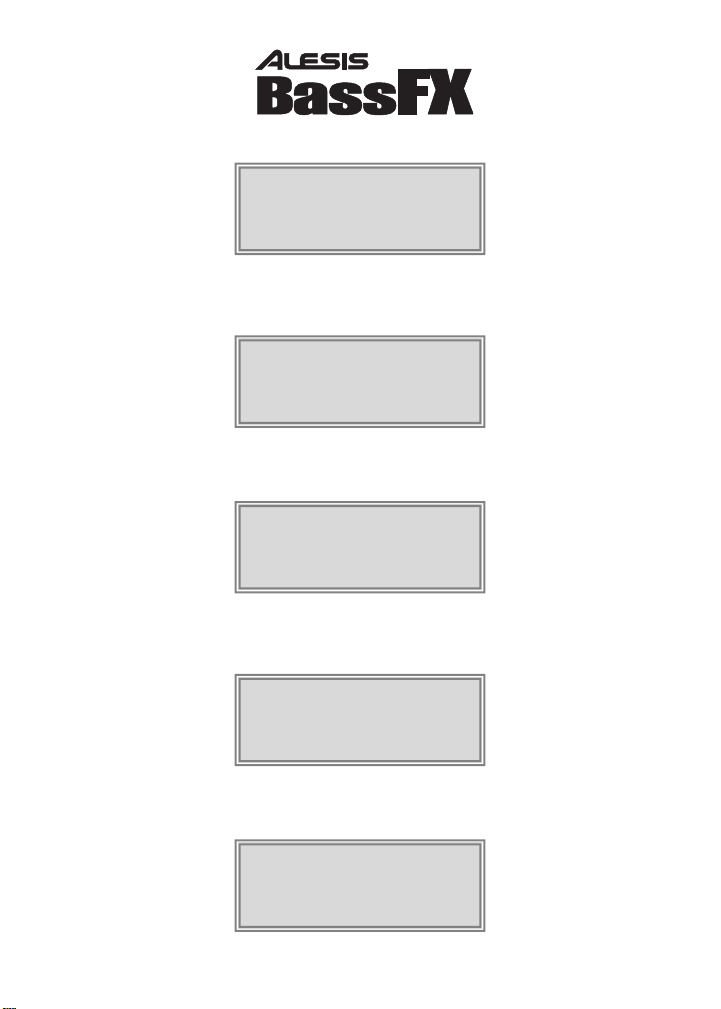
BassFX Hookup Diagram
9V
Adapter
Headphones
BassFX
Bass
Guitar
Control
Pedal
Amplifier
Quick Setup for the BassFX
1. Make sure all items listed on the front
of this guide are in the BassFX’s box.
2. Read the Important Safety Instructions
starting on page 7 of the User Manual.
3. Study the Hookup Diagram above.
4. Make sure all devices and instruments
are turned off and all gain knobs set to
zero.
5. Connect your bass and amplifier (and
control pedal and headphones if
applicable) to the BassFX in the
manner illustrated above. Refer to the
Connection Details below for details
on which cables to use.
6. Plug in all devices.
7. Experiment with the BassFX’s effect
combinations. Refer to the quick
reference on the next page for help.
8. When finished, turn off the amp before
disconnecting any equipment to
prevent damage to the speaker.
9. Go to http://www.alesis.com to
register the BassFX.
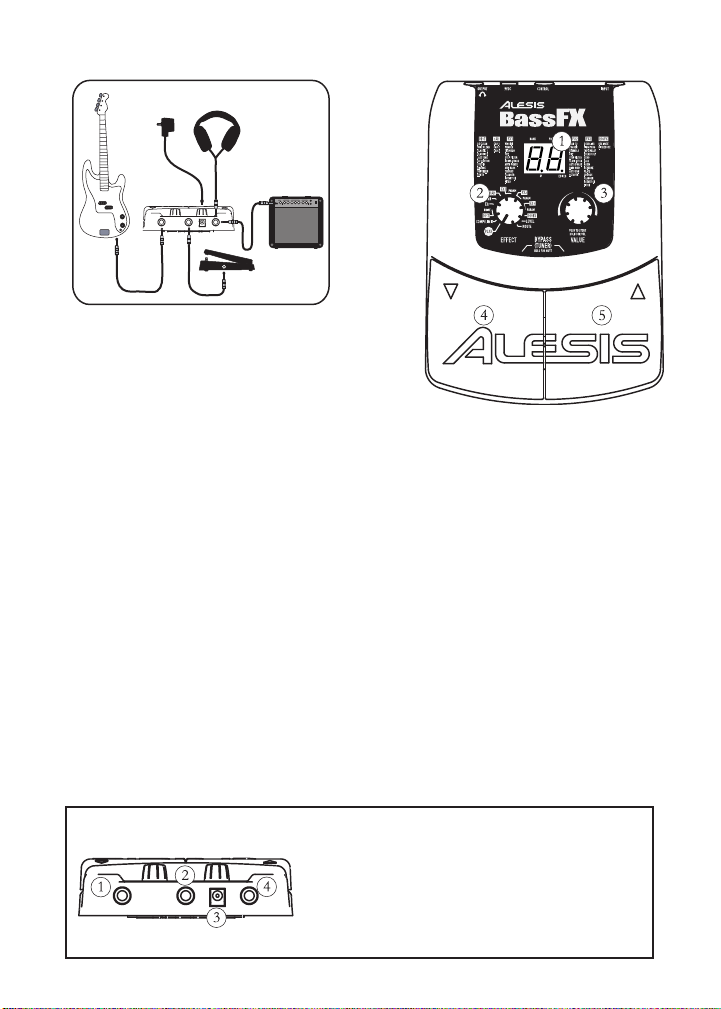
Features of the BassFX
1. Display – Indicates bank and program,
shows parameter values and displays
pitch in tuner mode.
2. EFFECT Knob – Puts the BassFX in
PLAY mode or EDIT mode. You are
in EDIT mode when you select a
module or parameter with this knob.
3. VALUE Knob – Adjusts parameter
values, program numbers and master
volume; stores changes.
4. Left Foot Pedal – Decrements
program number; when used with the
right foot pedal, puts the unit in
BYPASS and MUTE modes and
accesses the tuner.
5. Right Foot Pedal – Increments
program number; when used with the
left foot pedal, puts the unit in
BYPASS and MUTE modes and
accesses the tuner.
Connection Details
1. INPUT Jack – A 1/4” monophonic high impedance unbalanced
input. If you’re using battery power, the unit powers on when you
insert a plug here.
2. CONTROL Jack – a 1/4” jack where you can connect a control
pedal for controlling effects.
3. 9VDC Jack – compatible with most 9VDC adapters. The unit
powers on as soon as you connect the adapter.
4. OUTPUT Jack – a stereo 1/4” unbalanced jack for headphones.
You may use a stereo-to-mono Y cable to connect this to two
amplifiers.
Effect Quick Reference
Refer to chapter 10 of the User Manual
for more details on effect modules.
1. COMP/LIMIT – increasing levels of
compression (C1-C9) and limiting (L1L9).
2. DIST – various types of amp modeling.
3. DRIVE – controls the drive/gain for
the DIST module; control pedal may
be used.
4. EQ – 50 separate values that cover the
gamut of possible EQ settings. See
page 26 of the User Manual for details.
5. NR – noise reduction and hum
elimination working together. left digit
of the display shows the level of hum
elimination and right digit shows level
of noise reduction.
6. CAB – settings C1 – C3 simulate 4 x
10”, 4 x 12” and 1 x 15” cabinets
respectively.
7. FX1 – various mono effects; most have
a separate setting for pedal control.
8. PARAM – direct-control parameter for
FX1; for most effects, can be set to
pedal control independent of the FX1
setting.
9. FX2 – stereo versions of the effects
found in FX1, with several additions;
these also have settings for pedal
control.
10. PARAM – direct-control parameter for
FX2; for most effects, can be set to
pedal control independent of the FX2
setting.
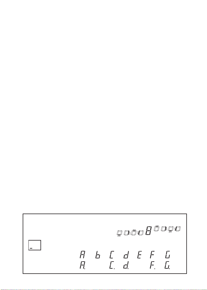
Visual Guide to Tuning
The bottom four segments rotate counterclockwise if
pitch is low. The top four rotate clockwise if the
pitch is high. An 8 means you’re in tune.
11. FX3 – various delay-based effects;
most have pedal-controlled versions.
12. PARAM – direct-control parameter for
FX3; for most effects, can be set to
pedal control independent of the FX3
setting.
13. DIGIFX – a couple of digital-sampling
effects with pedal-controlled versions.
14. LEVEL – the level of the current
program.
15. ROUTE – eight variations of the
routing order of all nine effect modules.
Selecting, Editing and Storing
Programs
1. In PLAY mode, use the foot pedals or
VALUE knob to select a program.
2. Turn the EFFECT knob to the module
or parameter you wish to edit.
3. Turn the VALUE knob to change the
value of the module or parameter.
4. To store your changes, press the
VALUE knob and then turn the knob
to select a store location. Press the
VALUE knob again to store the
program.
Using the Tuner
1. In PLAY mode, activate the tuner by
pressing both pedals at the same time
to enter BYPASS mode, or hold down
the pedals for more than half a second
to enter MUTE mode.
2. Play the open string you wish to tune.
Use the following guide when tuning:
Low
In tune
High
= no pitch detected.
Here are the 12 possible
pitches (a decimal point
indicates a sharp):
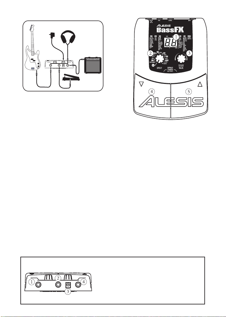
Diagrama de montaje de BassFX
Adaptador
de 9V
Guitarra
baja
BassFX
Auriculares
Instalación rápida para el BassFX
1. Asegúrese de que todos los artículos
incluidos al inicio de este manual están
incluidos en la caja del BassFX.
2. Lea las importantes instrucciones de
seguridad que comienzan en la página 7 del
Manual de usuario.
3. Estudie el diagrama de montaje que aparece
más arriba.
4. Asegúrese de que todos los dispositivos e
instrumentos están apagados y de que todos
los controles de ganancia están en posición
“cero”.
5. Conecte su guitarra y su amplificador (y
pedalera de control y auriculares si es
aplicable) al BassFX de la manera que se
muestra abajo. Remítase a “Detalles de
conexión” más abajo para detalles sobre qué
cables utilizar.
6. Enchufe todos los dispositivos.
7. Experimente con las combinaciones de
efectos de BassFX. Si necesita ayuda,
remítase a la referencia rápida en la página
siguiente.
8. Cuando haya terminado, apague el
amplificador antes de desconectar ningún
equipo para evitar daños al bafle.
Visite http://www.alesis.com para registrar el
9.
BassFX.
Amplificador
Pedal de
Control
Detalles de conexión
Características del BassFX
1. Display – Indica banco y programa, muestra
los valores del parámetro y puede visualizarse
el pitch en modo sintonizador.
2. Botón de EFECTOS – Pone el BassFX en
modo PLAY [Tocar] o EDIT [Editar]. Se
encuentra en modo EDITAR cuando
selecciona un módulo o parámetro con este
botón.
3. Botón de VALOR – Ajusta los valores del
parámetro, los números de programa y el
volumen del master; almacena los cambios.
4. Pedal del Pie Izquierdo – Disminuye el
número de programa, cuando se utiliza junto
con el pedal del pie derecho, pone la unidad
en los modos de BYPASS y MUTE
[SILENCIO] y accede al sintonizador.
6.
Pedal del Pie Derecho – Aumenta el
número de programa, cuando se utiliza junto
con el pedal del pie izquierdo, pone la unidad
en los modos de BYPASS y MUTE
[SILENCIO] y accede al sintonizador.
1. Jack de ENTRADA– Una entrada no balanceada de alta impedancia
monofónica de ¼”. Si está utilizando alimentación por batería, la
unidad se enciende cuando inserta en el enchufe aquí.
2. Jack de CONTROL – un jack de 1/4” donde puede conectar un
pedal de control para controlar los efectos.
3. Jack de 9VDC– compatible con la mayoría de los adaptadores
9VDC. Esta unidad se enciende cuando conecta el adaptador.
4. Jack de SALIDA– un jack estéreo de 1/4” no balanceado para
auriculares. Puede usar un stereo-a-mono Y cable para conectar esto
a dos amplificadores.
 Loading...