

Page 1

Part No. 060180-10, Rev. E
March 2005
OmniSwitch 6600 Family
Switch Management Guide
www.alcatel.com
Page 2

This user guide documents release 5.1.6 of the OmniSwitch 6600 Family.
The functionality described in this guide is subject to change without notice.
Copyright © 2005 by Alcatel Internetworking, Inc. All rights reserved. This document may not be reproduced in whole or in part without the express written permission of Alcatel Internetworking, Inc.
®
Alcatel
and Alcatel OmniVista
and the Alcatel logo are registered trademarks of Alcatel. Xylan®, OmniSwitch®, OmniStack®,
®
are registered trademarks of Alcatel Internetworking, Inc.
OmniAccess™, Omni Switch/Router™, PolicyView™, RouterView™, SwitchManager™, VoiceView™,
WebView™, X-Cell™, X-Vision™, and the Xylan logo are trademarks of Alcatel Internetworking, Inc.
This OmniSwitch product contains components which may be covered by one or more of the following
U.S. Patents:
• U.S. Patent No. 6,339,830
• U.S. Patent No. 6,070,243
• U.S. Patent No. 6,061,368
• U.S. Patent No. 5,394,402
• U.S. Patent No. 6,047,024
• U.S. Patent No. 6,314,106
• U.S. Patent No. 6,542,507
26801 West Agoura Road
Calabasas, CA 91301
(818) 880-3500 FAX (818) 880-3505
info@ind.alcatel.com
US Customer Support—(800) 995-2696
International Customer Support—(818) 878-4507
Internet—http://eservice.ind.alcatel.com
ii OmniSwitch 6600 Family Switch Management Guide March 2005
Page 3

Contents
About This Guide .......................................................................................................... xi
Supported Platforms .......................................................................................................... xi
Who Should Read this Manual? .......................................................................................xii
When Should I Read this Manual? ...................................................................................xii
What is in this Manual? .................................................................................................... xii
What is Not in this Manual? .............................................................................................xii
How is the Information Organized? ................................................................................xiii
Documentation Roadmap ................................................................................................xiii
Related Documentation .................................................................................................... xv
User Manual CD .............................................................................................................xvi
Technical Support ........................................................................................................... xvi
Chapter 1 Logging Into the Switch ............................................................................................1-1
In This Chapter ................................................................................................................1-1
Login Specifications ........................................................................................................1-2
Login Defaults .................................................................................................................1-2
Quick Steps for Logging Into the Switch ........................................................................1-3
Overview of Switch Login Components .........................................................................1-4
Management Interfaces ............................................................................................1-4
Logging Into the CLI .........................................................................................1-4
Using the WebView Management Tool ............................................................1-5
Using SNMP to Manage the Switch ..................................................................1-5
User Accounts ..........................................................................................................1-5
Using Telnet ....................................................................................................................1-6
Logging Into the Switch Via Telnet .........................................................................1-6
Starting a Telnet Session from the Switch ...............................................................1-6
Using FTP .......................................................................................................................1-7
Using FTP to Log Into the Switch ...........................................................................1-7
Using Secure Shell ..........................................................................................................1-8
Secure Shell Components .........................................................................................1-8
Secure Shell Interface ........................................................................................1-8
Secure Shell File Transfer Protocol ...................................................................1-8
Secure Shell Application Overview .........................................................................1-9
Secure Shell Authentication ...................................................................................1-10
Protocol Identification .....................................................................................1-10
Algorithm and Key Exchange .........................................................................1-10
OmniSwitch 6600 Family Switch Management Guide March 2005 iii
Page 4

Contents
Authentication Phase .......................................................................................1-10
Connection Phase ............................................................................................1-11
Starting a Secure Shell Session ..............................................................................1-11
Closing a Secure Shell Session ..............................................................................1-13
Log Into the Switch with Secure Shell FTP ...........................................................1-13
Closing a Secure Shell FTP Session ......................................................................1-14
Modifying the Login Banner .........................................................................................1-15
Modifying the Text Display Before Login .............................................................1-16
Configuring Login Parameters ......................................................................................1-17
Configuring the Inactivity Timer ..................................................................................1-17
Enabling the DNS Resolver ..........................................................................................1-18
Verifying Login Settings ...............................................................................................1-18
Chapter 2 Managing System Files .............................................................................................2-1
In This Chapter ................................................................................................................2-1
File Management Specifications .....................................................................................2-2
Switch Administration Overview ....................................................................................2-3
File Transfer .............................................................................................................2-3
Switch Directories ....................................................................................................2-4
File and Directory Management ......................................................................................2-5
Using Wildcards .......................................................................................................2-7
Multiple Characters ...........................................................................................2-7
Single Characters ...............................................................................................2-7
Directory Commands ...............................................................................................2-8
Determining Your Location in the File Structure ..............................................2-8
Changing Directories .........................................................................................2-9
Displaying Directory Contents ........................................................................2-10
Making a New Directory .................................................................................2-11
Displaying Directory Contents Including Subdirectories ................................2-12
Copying an Existing Directory ........................................................................2-12
Removing a Directory and its Contents ...........................................................2-13
File Commands ......................................................................................................2-14
Creating or Modifying Files ............................................................................2-14
Copy an Existing File ......................................................................................2-14
Move an Existing File or Directory .................................................................2-15
Change File Attribute and Permissions ...........................................................2-16
Delete an Existing File ....................................................................................2-16
Managing Files on Non Primary Switches ......................................................2-16
Utility Commands ..................................................................................................2-17
Displaying Free Memory Space ......................................................................2-17
Performing a File System Check .....................................................................2-17
Deleting the Entire File System .......................................................................2-18
Loading Software onto the Switch ................................................................................2-19
Using the Switch as an FTP Server ........................................................................2-19
Using the Switch as an FTP Client .........................................................................2-21
Using Secure Shell FTP .........................................................................................2-23
Closing a Secure Shell FTP Session ......................................................................2-23
ivOmniSwitch 6600 Family Switch Management Guide March 2005
Page 5

Contents
Using Zmodem .......................................................................................................2-24
Registering Software Image Files .................................................................................2-26
Directories on the Switch .......................................................................................2-26
Using the Install Command ....................................................................................2-27
Available Image Files .............................................................................................2-28
Application Examples for File Management ................................................................2-29
Transferring a File to the Switch Using FTP .........................................................2-29
Creating a File Directory on the Switch .................................................................2-30
FTP Client Application Example ....................................................................2-31
Creating a File Directory Using Secure Shell FTP ................................................2-32
Transfer a File Using Secure Shell FTP .................................................................2-34
Closing a Secure Shell FTP Session ......................................................................2-34
Verifying Directory Contents ........................................................................................2-34
Setting the System Clock ..............................................................................................2-35
Setting Date and Time ............................................................................................2-35
Date ..................................................................................................................2-35
Time Zone .......................................................................................................2-35
Time .................................................................................................................2-36
Daylight Savings Time Configuration ...................................................................2-37
Enabling DST ..................................................................................................2-38
Chapter 3 Configuring Network Time Protocol (NTP) ..........................................................3-1
In This Chapter ................................................................................................................3-1
NTP Specifications ..........................................................................................................3-2
NTP Defaults Table .........................................................................................................3-2
NTP Quick Steps .............................................................................................................3-3
NTP Overview ................................................................................................................3-4
Stratum .....................................................................................................................3-5
Using NTP in a Network ..........................................................................................3-5
Authentication ..........................................................................................................3-7
Configuring NTP .............................................................................................................3-8
Configuring the OmniSwitch as a Client .................................................................3-8
NTP Servers .............................................................................................................3-9
Using Authentication ..............................................................................................3-10
Verifying NTP Configuration .......................................................................................3-11
Chapter 4 Managing CMM Directory Content ........................................................................4-1
In This Chapter ................................................................................................................4-1
CMM Specifications .......................................................................................................4-2
CMM Files ......................................................................................................................4-3
CMM Software Directory Structure .........................................................................4-3
Where is the Switch Running From? .................................................................4-4
Software Rollback Feature .......................................................................................4-4
Software Rollback Configuration Scenarios for a Single Switch .....................4-5
Redundancy ..............................................................................................................4-9
OmniSwitch 6600 Family Switch Management Guide March 2005 v
Page 6

Contents
Redundancy Scenarios .......................................................................................4-9
Managing the Directory Structure (Non-Redundant) ...................................................4-13
Rebooting the Switch .............................................................................................4-13
Copying the Running Configuration to the Working Directory ............................4-15
Rebooting from the Working Directory .................................................................4-17
Copying the Working Directory to the Certified Directory ...................................4-20
Copying the Certified Directory to the Working Directory ...................................4-21
Show Currently Used Configuration ......................................................................4-22
Show Switch Files ..................................................................................................4-23
Managing Redundancy in a Stack .................................................................................4-24
Rebooting the Switch .............................................................................................4-24
Copying the Working Directory to the Certified Directory ...................................4-25
Synchronizing the Primary and Secondary CMMs ................................................4-26
Swapping the Primary CMM for the Secondary CMM .........................................4-28
Show Currently Used Configuration ......................................................................4-28
Emergency Restore of the boot.cfg File ........................................................................4-30
Can I Restore the boot.file While Running from Certified? ..................................4-30
Displaying CMM Conditions ........................................................................................4-31
Chapter 5 Using the CLI ...............................................................................................................5-1
CLI Specifications ...........................................................................................................5-2
CLI Overview ..................................................................................................................5-2
Online Configuration ................................................................................................5-2
Offline Configuration Using Configuration Files ....................................................5-3
Command Entry Rules and Syntax .................................................................................5-3
Text Conventions .....................................................................................................5-3
Using “Show” Commands .......................................................................................5-4
Using the “No” Form ...............................................................................................5-4
Using “Alias” Commands ........................................................................................5-4
Partial Keyword Completion ....................................................................................5-5
Command Help ...............................................................................................................5-5
Tutorial for Building a Command Using Help .........................................................5-7
CLI Services ....................................................................................................................5-9
Command Line Editing ............................................................................................5-9
Deleting Characters ...........................................................................................5-9
Recalling the Previous Command Line ...........................................................5-10
Inserting Characters .........................................................................................5-10
Syntax Checking ....................................................................................................5-11
Prefix Recognition ..................................................................................................5-11
Example for Using Prefix Recognition ...........................................................5-12
Prefix Prompt ...................................................................................................5-13
Command History ..................................................................................................5-13
Logging CLI Commands and Entry Results .................................................................5-15
Enabling Command Logging ..........................................................................5-15
Disabling Command Logging .........................................................................5-15
Viewing the Current Command Logging Status .............................................5-16
Viewing Logged CLI Commands and Command Entry Results ....................5-16
viOmniSwitch 6600 Family Switch Management Guide March 2005
Page 7

Contents
Customizing the Screen Display ...................................................................................5-17
Changing the Screen Size .......................................................................................5-17
Changing the CLI Prompt ......................................................................................5-17
Displaying Table Information ................................................................................5-18
Filtering Table Information ....................................................................................5-19
Multiple User Sessions ..................................................................................................5-20
Listing Other User Sessions ...................................................................................5-20
Listing Your Current Login Session ......................................................................5-21
Terminating Another Session .................................................................................5-22
Application Example .....................................................................................................5-23
Using a Wildcard to Filter Table Information ........................................................5-23
Verifying CLI Usage .....................................................................................................5-24
Chapter 6 Working With Configuration Files .........................................................................6-1
In This Chapter ................................................................................................................6-1
Configuration File Specifications ...................................................................................6-2
Tutorial for Creating a Configuration File ......................................................................6-2
Quick Steps for Applying Configuration Files ...............................................................6-4
Setting a File for Immediate Application .................................................................6-4
Setting an Application Session for a Date and Time ...............................................6-4
Setting an Application Session for a Specified Time Period ...................................6-5
Configuration Files Overview .........................................................................................6-6
Applying Configuration Files to the Switch ............................................................6-6
Verifying a Timed Session ................................................................................6-6
Cancelling a Timed Session ..............................................................................6-7
Configuration File Error Reporting ...................................................................6-7
Setting the Error File Limit ...............................................................................6-8
Syntax Checking ................................................................................................6-8
Displaying a Text File ..............................................................................................6-9
Text Editing on the Switch .......................................................................................6-9
Invoke the “Vi” Editor .......................................................................................6-9
Creating Snapshot Configuration Files .........................................................................6-10
Snapshot Feature List .............................................................................................6-10
User-Defined Naming Options ........................................................................6-11
Editing Snapshot Files .....................................................................................6-11
Verifying File Configuration .........................................................................................6-14
Chapter 7 Managing Switch User Accounts ............................................................................7-1
In This Chapter ................................................................................................................7-1
User Database Specifications ..........................................................................................7-2
User Account Defaults ....................................................................................................7-2
Overview of User Accounts ............................................................................................7-3
Startup Defaults ........................................................................................................7-4
Quick Steps for Network Administrator User Accounts ..........................................7-5
Quick Steps for Creating Customer Login User Accounts ......................................7-6
OmniSwitch 6600 Family Switch Management Guide March 2005 vii
Page 8

Contents
Default User Settings ...............................................................................................7-7
How User Settings Are Saved ..................................................................................7-7
Creating a User ................................................................................................................7-8
Removing a User ......................................................................................................7-8
User-Configured Password ......................................................................................7-8
Setting a Minimum Password Size ...........................................................................7-9
Configuring Password Expiration ............................................................................7-9
Default Password Expiration .............................................................................7-9
Specific User Password Expiration .................................................................7-10
Configuring Privileges for a User .................................................................................7-11
Setting Up SNMP Access for a User Account ..............................................................7-12
SNMP Access Without Authentication/Encryption ...............................................7-12
SNMP Access With Authentication/Encryption ....................................................7-13
Removing SNMP Access From a User ..................................................................7-13
Setting Up End-User Profiles ........................................................................................7-14
Creating End-User Profiles ....................................................................................7-15
Setting Up Port Ranges in a Profile .......................................................................7-15
Setting Up VLAN Ranges in a Profile ...................................................................7-15
Associating a Profile With a User ..........................................................................7-16
Removing a Profile From the Configuration ..........................................................7-16
Verifying the User Configuration .................................................................................7-16
Chapter 8 Managing Switch Security ........................................................................................8-1
In This Chapter ................................................................................................................8-1
Switch Security Specifications ........................................................................................8-2
Switch Security Defaults .................................................................................................8-2
Switch Security Overview ...............................................................................................8-3
Authenticated Switch Access ..........................................................................................8-4
AAA Servers—RADIUS or LDAP ..........................................................................8-4
Authentication-only—ACE/Server ..........................................................................8-4
Interaction With the User Database .........................................................................8-5
ASA and Authenticated VLANs ..............................................................................8-5
Configuring Authenticated Switch Access .....................................................................8-6
Quick Steps for Setting Up ASA ....................................................................................8-7
Setting Up Management Interfaces for ASA ..................................................................8-9
Enabling Switch Access .........................................................................................8-10
Configuring the Default Setting .............................................................................8-10
Using Secure Shell .................................................................................................8-11
Configuring Accounting for ASA .................................................................................8-12
Verifying the ASA Configuration .................................................................................8-13
viiiOmniSwitch 6600 Family Switch Management Guide March 2005
Page 9

Contents
Chapter 9 Using WebView ...........................................................................................................9-1
In This Chapter ................................................................................................................9-1
WebView CLI Defaults ...................................................................................................9-2
Browser Setup .................................................................................................................9-2
WebView CLI Commands ..............................................................................................9-3
Enabling/Disabling WebView ..................................................................................9-3
Enabling/Disabling SSL ...........................................................................................9-3
Quick Steps for Setting Up WebView ............................................................................9-4
WebView Overview ........................................................................................................9-4
WebView Page Layout .............................................................................................9-4
Banner ................................................................................................................9-5
Toolbar ..............................................................................................................9-5
Feature Options .................................................................................................9-6
View/Configuration Area ..................................................................................9-6
Configuring the Switch With WebView .........................................................................9-7
Accessing WebView ................................................................................................9-7
Home Page ...............................................................................................................9-8
Configuration Page ...................................................................................................9-9
Global Configuration Page ................................................................................9-9
Table Configuration Page ................................................................................9-10
Table Features .................................................................................................9-12
Adjacencies ............................................................................................................9-16
WebView Help ..............................................................................................................9-17
General WebView Help .........................................................................................9-17
Specific-page Help .................................................................................................9-17
Chapter 10 Using SNMP ...............................................................................................................10-1
In This Chapter ..............................................................................................................10-1
SNMP Specifications ....................................................................................................10-2
SNMP Defaults .............................................................................................................10-2
Quick Steps for Setting Up An SNMP Management Station .......................................10-3
Quick Steps for Setting Up Trap Filters ........................................................................10-4
Filtering by Trap Families ......................................................................................10-4
Filtering by Individual Traps ..................................................................................10-5
SNMP Overview ...........................................................................................................10-6
SNMP Operations ..................................................................................................10-6
Using SNMP for Switch Management ...................................................................10-7
Setting Up an SNMP Management Station .....................................................10-7
SNMP Versions ......................................................................................................10-7
SNMPv1 ..........................................................................................................10-7
SNMPv2 ..........................................................................................................10-8
SNMPv3 ..........................................................................................................10-8
SNMP Traps Table .................................................................................................10-9
Using SNMP For Switch Security ..............................................................................10-26
OmniSwitch 6600 Family Switch Management Guide March 2005 ix
Page 10

Contents
Community Strings (SNMPv1 and SNMPv2) .....................................................10-26
Configuring Community Strings ...................................................................10-26
Encryption and Authentication (SNMPv3) ..........................................................10-27
Configuring Encryption and Authentication .................................................10-27
Setting SNMP Security .................................................................................10-28
Working with SNMP Traps ........................................................................................10-29
Trap Filtering ........................................................................................................10-29
Filtering by Trap Families .............................................................................10-29
Filtering By Individual Trap ..........................................................................10-29
Authentication Trap ..............................................................................................10-30
Trap Management ................................................................................................10-30
Replaying Traps .............................................................................................10-30
Absorbing Traps ............................................................................................10-30
Sending Traps to WebView ...........................................................................10-30
SNMP MIB Information .............................................................................................10-31
MIB Tables ...........................................................................................................10-31
MIB Table Description ..................................................................................10-31
Industry Standard MIBs .......................................................................................10-32
Enterprise (Proprietary) MIBs ..............................................................................10-36
Verifying the SNMP Configuration ............................................................................10-39
Appendix A Software License and Copyright Statements .................................................... A-1
Alcatel License Agreement ............................................................................................ A-1
ALCATEL INTERNETWORKING, INC. (“AII”)
SOFTWARE LICENSE AGREEMENT ............................................................... A-1
Third Party Licenses and Notices ..................................................................................A-4
A. Booting and Debugging Non-Proprietary Software ..........................................A-4
B. The OpenLDAP Public License: Version 2.4, 8 December 2000 .....................A-4
C. Linux ..................................................................................................................A-5
D. GNU GENERAL PUBLIC LICENSE: Version 2, June 1991 .......................... A-5
E. University of California ...................................................................................A-10
F. Carnegie-Mellon University ............................................................................A-10
G. Random.c .........................................................................................................A-10
H. Apptitude, Inc. .................................................................................................A-11
I. Agranat .............................................................................................................A-11
J. RSA Security Inc. ............................................................................................A-11
K. Sun Microsystems, Inc. ....................................................................................A-11
L. Wind River Systems, Inc. ................................................................................A-12
M. Network Time Protocol Version 4 ...................................................................A-12
Index ...................................................................................................................... Index-1
xOmniSwitch 6600 Family Switch Management Guide March 2005
Page 11

About This Guide
This OmniSwitch 6600 Family Switch Management Guide describes basic attributes of your switch and
basic switch administration tasks. The software features described in this manual are shipped standard with
your OmniSwitch 6600 Family switch. These features are used when readying a switch for integration into
a live network environment.
Supported Platforms
This information in this guide applies to the following products:
• OmniSwitch 6624
• OmniSwitch 6648
• OmniSwitch 6600-U24
• OmniSwitch 6600-P24
• OmniSwitch 6602-24
• OmniSwitch 6602-48
OmniSwitch 6600 Family switches are next generation enterprise edge/workgroup switches. The
OmniSwitch 6624 and 6602-24 offer 24 copper 10/100 ports, the 6600-P24 offers 24 copper 10/100 Power
over Ethernet (PoE) ports, the 6648 and 6602-48 offer 48 copper 10/100 ports, and the 6600-U24 offers 24
fiber 100 ports.
In addition, OmniSwitch 6624/6600-U24/6648 switches have one expansion port that can be used for a
Gigabit Ethernet uplink module and another expansion port that can be used for a Gigabit Ethernet uplink
or a stacking module while the 6602-24/6602-48 switches offer fixed Gigabit Ethernet uplinks and fixed
stacking ports. The stacking ports on all OmniSwitch 6600 Family switches allow two to eight
OmniSwitch 6600 Family switches to be configured as one virtual chassis known as a stack.
Note. All references to OmniSwitch 6624 and 6648 switches also apply to the OmniSwitch 6600-U24,
6600-P24, 6602-24, and 6602-48 unless specified otherwise.
Unsupported Platforms
The information in this guide does not apply to the following products:
• OmniSwitch 6800, 7700, 7800, or 8800
• OmniSwitch (original version with no numeric model name)
• Omni Switch/Router
• OmniStack
• OmniAccess
OmniSwitch 6600 Family Switch Management Guide March 2005 page xi
Page 12

Who Should Read this Manual? About This Guide
Who Should Read this Manual?
The audience for this user guide is network administrators and IT support personnel who need to configure, maintain, and monitor switches and routers in a live network. However, anyone wishing to gain
knowledge on how fundamental software features are implemented in the OmniSwitch 6600 Family will
benefit from the material in this configuration guide.
When Should I Read this Manual?
Read this guide as soon as your switch is up and running and you are ready to familiarize yourself with
basic software functions. You should have already stepped through the first login procedures and read the
brief software overviews in the OmniSwitch 6600 Family Getting Started Guide.
You should have already set up a switch password and be familiar with the very basics of the switch software. This manual will help you understand the switch’s directory structure, the Command Line Interface
(CLI), configuration files, basic security features, and basic administrative functions. The features and
procedures in this guide will help form a foundation that will allow you to configure more advanced
switching features later.
What is in this Manual?
This configuration guide includes information about the following features:
• Basic switch administrative features, such as file editing utilities, procedures for loading new software,
and setting up system information (name of switch, date, time).
• Configurations files, including snapshots, off-line configuration, time-activated file download.
• The CLI, including on-line configuration, command-building help, syntax error checking, and line edit-
ing.
• Basic security features, such as switch access control and customized user accounts.
• SNMP
• Web-based management (WebView)
What is Not in this Manual?
The configuration procedures in this manual primarily use Command Line Interface (CLI) commands in
examples. CLI commands are text-based commands used to manage the switch through serial (console
port) connections or via Telnet sessions. This guide does include introductory chapters for alternative
methods of managing the switch, such as web-based (WebView) and SNMP management. However the
primary focus of this guide is managing the switch through the CLI.
Further information on WebView can be found in the context-sensitive on-line help available with that
application.
This guide does not include documentation for the OmniVista network management system. However,
OmniVista includes a complete context-sensitive on-line help system.
page xii OmniSwitch 6600 Family Switch Management Guide March 2005
Page 13

About This Guide How is the Information Organized?
This guide provides overview material on software features, how-to procedures, and tutorials that will
enable you to begin configuring your OmniSwitch. However, it is not intended as a comprehensive reference to all CLI commands available in the OmniSwitch. For such a reference to all OmniSwitch 6600
Family CLI commands, consult the OmniSwitch CLI Reference Guide.
How is the Information Organized?
Each chapter in this guide includes sections that will satisfy the information requirements of casual readers, rushed readers, serious detail-oriented readers, advanced users, and beginning users.
Quick Information. Most chapters include a specifications table that lists RFCs and IEEE specifications
supported by the software feature. In addition, this table includes other pertinent information such as minimum and maximum values and sub-feature support. Some chapters include a defaults table that lists the
default values for important parameters along with the CLI command used to configure the parameter.
Many chapters include Quick Steps sections, which are procedures covering the basic steps required to get
a software feature up and running.
In-Depth Information. All chapters include overview sections on software features as well as on selected
topics of that software feature. Topical sections may often lead into procedure sections that describe how
to configure the feature just described. Many chapters include tutorials or application examples that help
convey how CLI commands can be used together to set up a particular feature.
Documentation Roadmap
The OmniSwitch user documentation suite was designed to supply you with information at several critical
junctures of the configuration process. The following section outlines a roadmap of the manuals that will
help you at each stage of the configuration process. Under each stage, we point you to the manual or
manuals that will be most helpful to you.
Stage 1: Using the Switch for the First Time
Pertinent Documentation: OmniSwitch 6600 Family Getting Started Guide
Release Notes
A hard-copy OmniSwitch 6600 Family Getting Started Guide is included with your switch; this guide
provides all the information you need to get your switch up and running the first time. This guide provides
information on unpacking the switch, rack mounting the switch, installing uplink and stacking modules,
unlocking access control, setting the switch’s IP address, setting up a password, and setting up stacks. It
also includes succinct overview information on fundamental aspects of the switch, such as hardware
LEDs, the software directory structure, stacking, CLI conventions, and web-based management.
At this time you should also familiarize yourself with the Release Notes that accompanied your switch.
This document includes important information on feature limitations that are not included in other user
guides.
OmniSwitch 6600 Family Switch Management Guide March 2005 page xiii
Page 14

Documentation Roadmap About This Guide
Stage 2: Gaining Familiarity with Basic Switch Functions
Pertinent Documentation: OmniSwitch 6600 Family Hardware Users Guide
OmniSwitch 6600 Family Switch Management Guide
Once you have your switch up and running, you will want to begin investigating basic aspects of its hard
ware and software. Information about OmniSwitch 6600 Family hardware is provided in the OmniSwitch
6600 Family Hardware Users Guide. This guide provides specifications, illustrations, and descriptions of
all hardware components—chassis, power supplies, uplink and stacking modules, and cooling fans. They
also include steps for common procedures, such as removing and installing switch components.
The OmniSwitch 6600 Family Switch Management Guide is the primary user guide for the basic software
features on a single switch. This guide contains information on the switch directory structure, basic file
and directory utilities, switch access security, SNMP, and web-based management. It is recommended that
you read this guide before connecting your switch to the network.
Note. The OmniSwitch 6600 Family Switch Management Guide was originally known as the “OmniSwitch
6624/6648 Switch Management Guide.”
Stage 3: Integrating the Switch Into a Network
Pertinent Documentation: OmniSwitch 6600 Family Network Configuration Guide
OmniSwitch 6600 Family Advanced Routing Configuration Guide
When you are ready to connect your switch to the network, you will need to learn how the OmniSwitch
implements fundamental software features, such as 802.1Q, VLANs, Spanning Tree, and network routing
protocols. The OmniSwitch 6600 Family Network Configuration Guide contains overview information,
procedures and examples on how standard networking technologies are configured in the OmniSwitch
6600 Family.
Note. The OmniSwitch 6600 Family Network Configuration Guide was originally known as the
“OmniSwitch 6624/6648 Network Configuration Guide.”
The OmniSwitch 6600 Family Advanced Routing Configuration Guide includes configuration information
for networks using Open Shortest Path First (OSPF).
Note. The OmniSwitch 6600 Family Advanced Routing Configuration Guide was originally known as the
“OmniSwitch 66/24/6648 Advanced Routing Configuration Guide”
Anytime
The OmniSwitch CLI Reference Guide contains comprehensive information on all CLI commands
supported by the switch. This guide includes syntax, default, usage, example, related CLI command, and
CLI-to-MIB variable mapping information for all CLI commands supported by the switch. This guide can
be consulted anytime during the configuration process to find detailed and specific information on each
CLI command.
page xiv OmniSwitch 6600 Family Switch Management Guide March 2005
Page 15

About This Guide Related Documentation
Related Documentation
The following are the titles and descriptions of all the OmniSwitch 6600 Family user manuals:
• OmniSwitch 6600 Family Getting Started Guide
Describes the hardware and software procedures for getting an OmniSwitch 6600 Family switch up
and running. Also provides information on fundamental aspects of OmniSwitch software and stacking
architecture.
• OmniSwitch 6600 Family Hardware Users Guide
Complete technical specifications and procedures for all OmniSwitch 6600 Family chassis, power
supplies, fans, and uplink and stacking modules.
• OmniSwitch CLI Reference Guide
Complete reference to all CLI commands supported on the OmniSwitch 6600, 6800, 7700, 7800, and
8800. Includes syntax definitions, default values, examples, usage guidelines, and CLI-to-MIB variable mappings.
• OmniSwitch 6600 Family Switch Management Guide
Includes procedures for readying an individual switch for integration into a network. Topics include
the software directory architecture, image rollback protections, authenticated switch access, managing
switch files, system configuration, using SNMP, and using web management software (WebView).
• OmniSwitch 6600 Family Network Configuration Guide
Includes network configuration procedures and descriptive information on all the major software
features and protocols included in the base software package. Chapters cover Layer 2 information
(Ethernet and VLAN configuration), Layer 3 information, security options (authenticated VLANs),
Quality of Service (QoS), and link aggregation.
• OmniSwitch 6600 Family Advanced Routing Configuration Guide
Includes network configuration procedures and descriptive information on all the software features and
protocols included in the advanced routing software package OSPF.
• Technical Tips, Field Notices
Includes information published by Alcatel’s Customer Support group.
• Release Note
Includes critical Open Problem Reports, feature exceptions, and other important information on the
features supported in the current release and any limitations to their support.
OmniSwitch 6600 Family Switch Management Guide March 2005 page xv
Page 16
User Manual CD About This Guide
User Manual CD
All user guides for the OmniSwitch 6600 Family are included on the User Manual CD that accompanied
your switch. This CD also includes user guides for other Alcatel data enterprise products. In addition, it
contains a stand-alone version of the on-line help system that is embedded in the OmniVista network
management application.
Besides the OmniVista documentation, all documentation on the User Manual CD is in
requires the Adobe Acrobat Reader program for viewing. Acrobat Reader freeware is available at
www.adobe.com.
Note. In order to take advantage of the documentation CD’s global search feature, it is recommended that
you select the option for searching PDF files before downloading Acrobat Reader freeware.
To verify that you are using Acrobat Reader with the global search option, look for the following button in
the toolbar:
Note. When printing pages from the documentation PDFs, de-select Fit to Page if it is selected in your
print dialog. Otherwise pages may print with slightly smaller margins.
PDF format and
Technical Support
An Alcatel service agreement brings your company the assurance of 7x24 no-excuses technical support.
You’ll also receive regular software updates to maintain and maximize your Alcatel product’s features and
functionality and on-site hardware replacement through our global network of highly qualified service
delivery partners. Additionally, with 24-hour-a-day access to Alcatel’s Service and Support web page,
you’ll be able to view and update any case (open or closed) that you have reported to Alcatel’s technical
support, open a new case or access helpful release notes, technical bulletins, and manuals. For more information on Alcatel’s Service Programs, see our web page at eservice.ind.alcatel.com, call us at 1-800-9952696, or email us at support@ind.alcatel.com.
page xvi OmniSwitch 6600 Family Switch Management Guide March 2005
Page 17

1 Logging Into the Switch
Logging into the switch may be done locally or remotely. Management tools include: the Command Line
Interface (CLI), which may be accessed locally via the console port, or remotely via Telnet; WebView,
which requires an HTTP client (browser) on a remote workstation; and SNMP, which requires an SNMP
manager (such as Alcatel’s OmniVista or HP OpenView) on the remote workstation. Secure sessions are
available using the Secure Shell interface. File transfers can be done via FTP or Secure Shell FTP.
In This Chapter
This chapter describes the basics of logging into the switch to manage the switch through the CLI. It
includes information about using Telnet, FTP, and Secure Shell for logging into the switch as well as
information about using the switch to start a Telnet or Secure Shell session on another device. It also
includes information about managing sessions and specifying a DNS resolver. For more details about the
syntax of referenced commands, see the OmniSwitch CLI Reference Guide.
Configuration procedures described in this chapter include:
• “Quick Steps for Logging Into the Switch” on page 1-3
• “Using Telnet” on page 1-6
• “Using FTP” on page 1-7
• “Using Secure Shell” on page 1-8
• “Modifying the Login Banner” on page 1-15
• “Configuring Login Parameters” on page 1-17
• “Enabling the DNS Resolver” on page 1-18
Management access is disabled (except through the console port) unless specifically enabled by a network
administrator. For more information about management access and methods, use the table here as a guide:
For more information about... See...
Enabling or “unlocking” management interfaces
on the switch
Authenticating users to manage the switch Chapter 8, “Managing Switch Security”
Creating user accounts directly on the switch Chapter 7, “Managing Switch User Accounts”
Using the CLI Chapter 5, “Using the CLI”
Using WebView to manage the switch Chapter 9, “Using WebView”
Getting Started Guide or
Chapter 8, “Managing Switch Security”
Using SNMP to manage the switch Chapter 10, “Using SNMP”
OmniSwitch 6600 Family Switch Management Guide March 2005 page 1-1
Page 18

Login Specifications Logging Into the Switch
Login Specifications
Telnet clients supported Any standard Telnet client.
FTP clients supported Any standard FTP client.
HTTP (WebView) clients supported
Secure Shell clients supported Any standard Secure Shell client (Secure Shell
SNMP clients supported Any standard SNMP manager (such as HP Open-
– Internet Explorer for Windows NT, Windows
XP, and Windows 2000, version 5.5
– Netscape for Windows NT, Windows XP, and
Windows 2000, version 4.7
– Netscape for Sun OS 2.8, version 4.7
– Netscape for HP-UX 11.0, version 4.7.
Version 2).
Vie w).
Login Defaults
Access to managing the switch is always available for the admin user through the console port, even if
management access to the console port is disabled
Parameter Description Command Default
Session login attempts allowed
before the TCP connection is
closed.
session login-attempt 3 attempts
Timeout period allowed for
session login before the TCP
connection is closed.
Inactivity timeout period. The
length of time the switch can
remain idle during a login
session before the switch will
close the session.
session login-timeout 55 seconds
session timeout 4 minutes
page 1-2 OmniSwitch 6600 Family Switch Management Guide March 2005
Page 19

Logging Into the Switch Quick Steps for Logging Into the Switch
Quick Steps for Logging Into the Switch
The following procedure assumes that you have set up the switch as described in your OmniSwitch Getting
Started Guide and Hardware Users Guide. Setup includes:
• Connecting to the switch via the console port.
• Setting up the Ethernet Management Port (EMP) through the switch’s boot prompt.
• Enabling (or “unlocking”) management interfaces types (Telnet, FTP, HTTP, SNMP, and Secure
Shell) through the aaa authentication command for the interface you are using. Note that Telnet, FTP,
and Secure Shell are used to log into the switch’s Command Line Interface (CLI). For detailed information about enabling session types, see Chapter 8, “Managing Switch Security.”
1 If you are connected to the switch via the console port, your terminal will automatically display the
switch login prompt. If you are connected remotely, you must enter the switch IP address in your Telnet,
FTP, or Secure Shell client (typically the IP address of the EMP). The login prompt then displays.
2 At the login prompt, enter the admin username. At the password prompt, enter the switch password.
(Alternately, you may enter any valid username and password.) The switch’s default welcome banner will
display, followed by the CLI prompt.
Welcome to the Alcatel OmniSwitch 6000
Software Version 5.1 Development, September 2, 2002.
Copyright(c), 1994-2002 Alcatel Internetworking Inc. All Rights reserved.
OmniSwitch(TM) is a trademark of Alcatel Internetworking, Inc. registered in the
United States Patent and Trademark Office.
You are now logged into the CLI. For information about changing the welcome banner, see “Modifying
the Login Banner” on page 1-15.
For information about changing the login prompt, see Chapter 5, “Using the CLI.”
For information about setting up additional user accounts locally on the switch, see Chapter 7, “Managing
Switch User Accounts.”
OmniSwitch 6600 Family Switch Management Guide March 2005 page 1-3
Page 20
Overview of Switch Login Components Logging Into the Switch
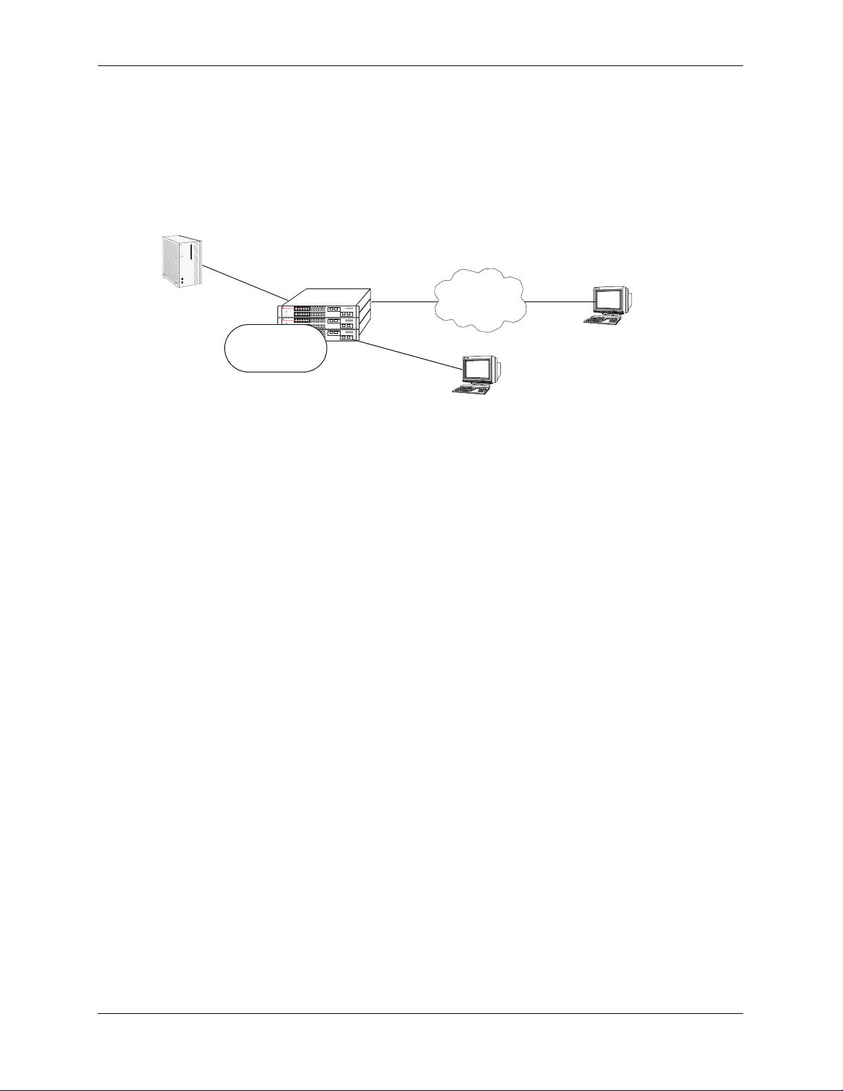
Overview of Switch Login Components
Switch access components include access methods (or interfaces) and user accounts stored on the local
user database in the switch and/or on external authentication servers. Each access method, except the
console port, must be enabled or “unlocked” on the switch before users can access the switch through that
interface.
OmniSwitch
Authentication
Server
OmniSwitch 6648
OmniSwitch 6648
OmniSwitch 6648
local user
database
remote user
Login via Secure Shell, Telnet,
FTP, HTTP, or SNMP
local user
Login via the console port.
Switch Login Components
Management Interfaces
Logging into the switch may be done locally or remotely. Remote connections may be secure or insecure,
depending on the method. Management interfaces are enabled using the aaa authentication command.
This command also requires specifying the external servers and/or local user database that will be used to
authenticate users. The process of authenticating users to manage the switch is called Authenticated
Switch Access (ASA). Authenticated Switch Access is described in detail in Chapter 8, “Managing Switch
Security.”
An overview of management methods is listed here:
Logging Into the CLI
• Console port—A direct connection to the switch through the console port. The console port is always
enabled for the default user account. For more information about connecting to the console port, see
your OmniSwitch Hardware Users Guide.
• Telnet—Any standard Telnet client may be used for remote login to the switch. This method is not
secure. For more information about using Telnet to access the switch, see “Using Telnet” on page 1-6.
• FTP—Any standard FTP client may be used for remote login to the switch. This method is not secure.
See “Using FTP” on page 1-7.
• Secure Shell—Any standard Secure Shell client may be used for remote login to the switch. See
“Using Secure Shell” on page 1-8.
page 1-4 OmniSwitch 6600 Family Switch Management Guide March 2005
Page 21

Logging Into the Switch Overview of Switch Login Components
Using the WebView Management Tool
• HTTP—The switch has a Web browser management interface for users logging in via HTTP. This
management tool is called WebView. For more information about using WebView, see Chapter 9,
“Using WebView.”
Using SNMP to Manage the Switch
• SNMP—Any standard SNMP browser may be used for logging into the switch. See Chapter 10,
“Using SNMP.”
User Accounts
User accounts may be configured and stored directly on the switch, and user accounts may also be configured and stored on an external authentication server or servers.
The accounts include a username and password. In addition, they also specify the user’s privileges or enduser profile, depending on the type of user account. In either case, the user is given read-only or read-write
access to particular commands.
• Local User Database
The user command creates accounts directly on the switch. See Chapter 7, “Managing Switch User
Accounts,”for information about creating accounts on the switch.
• External Authentication Servers
The switch may be set up to communicate with external authentication servers that contain user information. The user information includes usernames and passwords; it may also include privilege information or
reference an end-user profile name.
For information about setting up the switch to communicate with external authentication servers, see the
OmniSwitch 6600 Family Network Configuration Guide.
OmniSwitch 6600 Family Switch Management Guide March 2005 page 1-5
Page 22

Using Telnet Logging Into the Switch
Using Telnet
Telnet may be used to log into the switch from a remote station. All of the standard Telnet commands are
supported by software in the switch. When Telnet is used to log in, the switch is acting as a Telnet server.
A Telnet session may also be initiated from the switch itself during a login session. In this case, the switch
is acting as a Telnet client.
Logging Into the Switch Via Telnet
Before you can log into the OmniSwitch using a Telnet interface, the telnet option of the aaa
authentication command must be enabled. Once enabled, any standard Telnet client may be used to log
into the switch. To log into the switch, open your Telnet application and enter the switch’s IP address (the
IP address will typically be the same as the one configured for the EMP). The switch’s welcome banner
and login prompt display.
Note. A Telnet connection is not secure. Secure Shell is recommended instead of Telnet or FTP as a
secure method of accessing the switch.
Starting a Telnet Session from the Switch
At any time during a login session on the switch, you can initiate a Telnet session to another switch (or
some other device) by using the telnet CLI command and the relevant IP address. The following shows an
example of telnetting to another OmniSwitch with an IP address of 10.255.10.123.
-> telnet 10.255.10.123
Trying 10.255.10.123...
Connected to 10.255.10.123.
Escape character is '^]'.
login :
Here, you must enter a valid username and password. Once login is completed, the OmniSwitch welcome
banner will display as follows:
login : admin
password :
Welcome to the Alcatel OmniSwitch 6000
Software Version 5.1.2.125, December 13, 2002.
Copyright(c), 1994-2002 Alcatel Internetworking, Inc. All Rights reserved.
OmniSwitch(TM) is a trademark of Alcatel Internetworking, Inc. registered
in the United States Patent and Trademark Office.
page 1-6 OmniSwitch 6600 Family Switch Management Guide March 2005
Page 23

Logging Into the Switch Using FTP
Using FTP
The OmniSwitch can function as an FTP server. Any standard FTP client may be used.
Note. An FTP connection is not secure. Secure Shell is recommended instead of FTP or Telnet as a secure
method of accessing the switch.
Using FTP to Log Into the Switch
You can access the OmniSwitch with a standard FTP application. To login to the switch, start your FTP
client. Where the FTP client asks for “Name”, enter the IP address of your switch. Where the FTP client
asks for “User ID”, enter the username of your login account on the switch. Where the FTP client asks for
“Password”, enter your switch password.
Note. If you are using Authenticated Switch Access (ASA), the port interface must be authenticated for
FTP use and the username profile must have permission to use FTP. Otherwise the switch will not accept
an FTP login. For information about ASA, refer to Chapter 8, “Managing Switch Security.”
Note. You must use the binary mode (bin) to transfer image files via FTP.
OmniSwitch 6600 Family Switch Management Guide March 2005 page 1-7
Page 24

Using Secure Shell Logging Into the Switch
Using Secure Shell
The OmniSwitch Secure Shell feature provides a secure mechanism that allows you to log in to a remote
switch, to execute commands on a remote device, and to move files from one device to another. Secure
Shell provides secure, encrypted communications even when your transmission is between two untrusted
hosts or over an unsecure network. Secure Shell protects against a variety of security risks including the
following:
• IP spoofing
• IP source routing
• DNS spoofing
• Interception of clear-text passwords and other data by intermediate hosts
• Manipulation of data by users on intermediate hosts
Note. The OmniSwitch supports Secure Shell Version 2 only.
Secure Shell Components
The OmniSwitch includes both client and server components of the Secure Shell interface and the Secure
Shell FTP file transfer protocol. SFTP is a subsystem of the Secure Shell protocol. All Secure Shell FTP
data are encrypted through a Secure Shell channel.
Since Secure Shell provides a secure session, the Secure Shell interface and SFTP are recommended
instead of the Telnet program or the FTP protocol for communications over TCP/IP for sending file
transfers. Both Telnet and FTP are available on the OmniSwitch but they do not support encrypted
passwords.
Note. Secure Shell may only be used to log into the switch to manage the switch. It cannot be used for
Layer 2 authentication through the switch.
Secure Shell Interface
The Secure Shell interface is invoked when you enter the ssh command. After the authentication process
between the client and the server is complete, the remote Secure Shell interface runs in the same way as
Telnet. Refer to “Starting a Secure Shell Session” on page 1-11 to for detailed information.
Secure Shell File Transfer Protocol
Secure Shell FTP is the standard file transfer protocol used with Secure Shell version 2. Secure Shell FTP
is an interactive file transfer program (similar to the industry standard FTP) which performs all file
transfer operations over a Secure Shell connection.
You invoke the Secure Shell FTP protocol by using the sftp command. Once the authentication phase is
completed, the Secure Shell FTP subsystem runs. Secure Shell FTP connects and logs into the specified
host, then enters an interactive command mode. Refer to “Starting a Secure Shell Session” on page 1-11
for detailed information.
page 1-8 OmniSwitch 6600 Family Switch Management Guide March 2005
Page 25
Logging Into the Switch Using Secure Shell
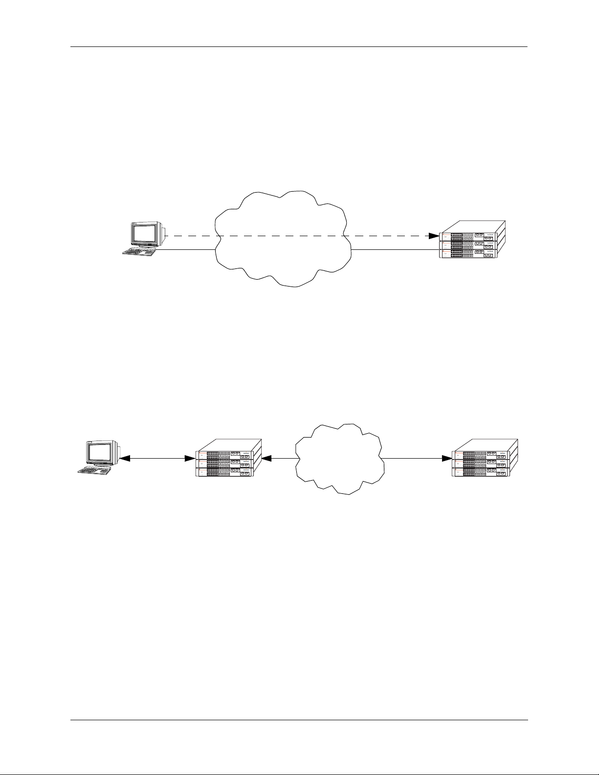
Secure Shell Application Overview
Secure Shell is an access protocol used to establish secured access to your OmniSwitch. The Secure Shell
protocol can be used to manage an OmniSwitch directly or it can provide a secure mechanism for
managing network servers through the OmniSwitch.
The drawing below illustrates the Secure Shell being used as an access protocol replacing Telnet to
manage the OmniSwitch. Here, the user terminal is connected through the network to the switch.
Secure Shell
OmniSwitch 6648
OmniSwitch 6648
OmniSwitch 6648
Network
Terminal
OmniSwitch
Secure Shell Used as an Access Protocol
The drawing below shows a slightly different application. Here, a terminal connected to a single
OmniSwitch acting as a Secure Shell client as an entry point into the network. In this scenario, the client
portion of the Secure Shell software is used on the connecting OmniSwitch and the server portion of
Secure Shell is used on the switches or servers being managed.
Secure Shell
Terminal
Access Protocol
OmniSwitch 6648
OmniSwitch 6648
OmniSwitch 6648
OmniSwitch Secure
Shell Client
Network
Secure Shell
OmniSwitch 6648
OmniSwitch 6648
OmniSwitch 6648
Secure Shell
Server
OmniSwitch as a Secure Shell Client
OmniSwitch 6600 Family Switch Management Guide March 2005 page 1-9
Page 26

Using Secure Shell Logging Into the Switch
Secure Shell Authentication
Secure Shell authentication is accomplished in several phases using industry standard algorithms and
exchange mechanisms. The authentication phase is identical for Secure Shell and Secure Shell SFTP. The
following sections describe the process in detail.
Protocol Identification
When the Secure Shell client in the OmniSwitch connects to a Secure Shell server, the server accepts the
connection and responds by sending back an identification string. The client will parse the server’s identification string and send an identification string of its own. The purpose of the identification strings is to
validate that the attempted connection was made to the correct port number. The strings also declare the
protocol and software version numbers. This information is needed on both the client and server sides for
debugging purposes.
At this point, the protocol identification strings are in human-readable form. Later in the authentication
process, the client and the server switch to a packet-based binary protocol, which is machine readable
only.
Algorithm and Key Exchange
The OmniSwitch Secure Shell server is identified by one or several host-specific DSA keys. Both the
client and server process the key exchange to choose a common algorithm for encryption, signature, and
compression. This key exchange is included in the Secure Shell transport layer protocol. It uses a key
agreement to produce a shared secret that cannot be determined by either the client or the server alone. The
key exchange is combined with a signature and the host key to provide host authentication. Once the
exchange is completed, the client and the server turn encryption on using the selected algorithm and key.
The following elements are supported:
Host Key Type DSA
Cipher Algorithms AES, Blowfish, Cast, 3DES, Arcfour, Rijndael
Signature Algorithms MD5, SHA1
Compression Algorithms None Supported
Key Exchange Algorithms diffie-hellman-group-exchange-sha1
diffie-hellman-group1-sha1
Note. The OmniSwitch generates a 512 bit DSA host key at initial startup. The DSA key on the switch is
made up of two files contained in the /flash/network directory; the public key is called
ssh_host_dsa_key.pub, and the private key is called ssh_host_dsa_key. To generate a different DSA key,
use the Secure Shell tools available on your Unix or Windows system and copy the files to the /flash/
network directory on your switch. The new DSA key will take effect after the OmniSwitch is rebooted.
Authentication Phase
When the client tries to authenticate, the server determines the process used by telling the client which
authentication methods can be used. The client has the freedom to attempt several methods listed by the
server. The server will disconnect itself from the client if a certain number of failed authentications are
attempted or if a timeout period expires. Authentication is performed independent of whether the Secure
Shell interface or the SFTP file transfer protocol will be implemented.
page 1-10 OmniSwitch 6600 Family Switch Management Guide March 2005
Page 27

Logging Into the Switch Using Secure Shell
Connection Phase
After successful authentication, both the client and the server process the Secure Shell connection
protocol. The OmniSwitch supports one channel for each Secure Shell connection. This channel can be
used for a Secure Shell session or a Secure Shell FTP session.
Starting a Secure Shell Session
To start a Secure Shell session from an OmniSwitch, issue the ssh command and identify the IP address
for the device you are connecting to.
Note. You can only use a host name instead of an IP address if the DNS resolver has been configured and
enabled. If not, you must specify an IP address. See Chapter 2, “Managing System Files,” for details.
Note. Use of the cmdtool OpenWindows support facility is not recommended over Secure Shell connections with an external server.
The following command establishes a Secure Shell interface from the local OmniSwitch to IP address
11.333.30.135.
-> ssh 11.333.30.135
login as:
You must have a login and password that is recognized by the IP address you specify. When you enter
your login, the device you are logging in to will request your password as shown here.
-> ssh 11.333.10.135
login as: rrlogin1
rrlogin1's password for keyboard-interactive method:
Once the Secure Shell session is established, you can use the remote device specified by the IP address on
a secure connection from your OmniSwitch.
Note. The login parameters for Secure Shell session login parameters can be affected by the session login-
attempt and session login-timeout CLI commands.
OmniSwitch 6600 Family Switch Management Guide March 2005 page 1-11
Page 28
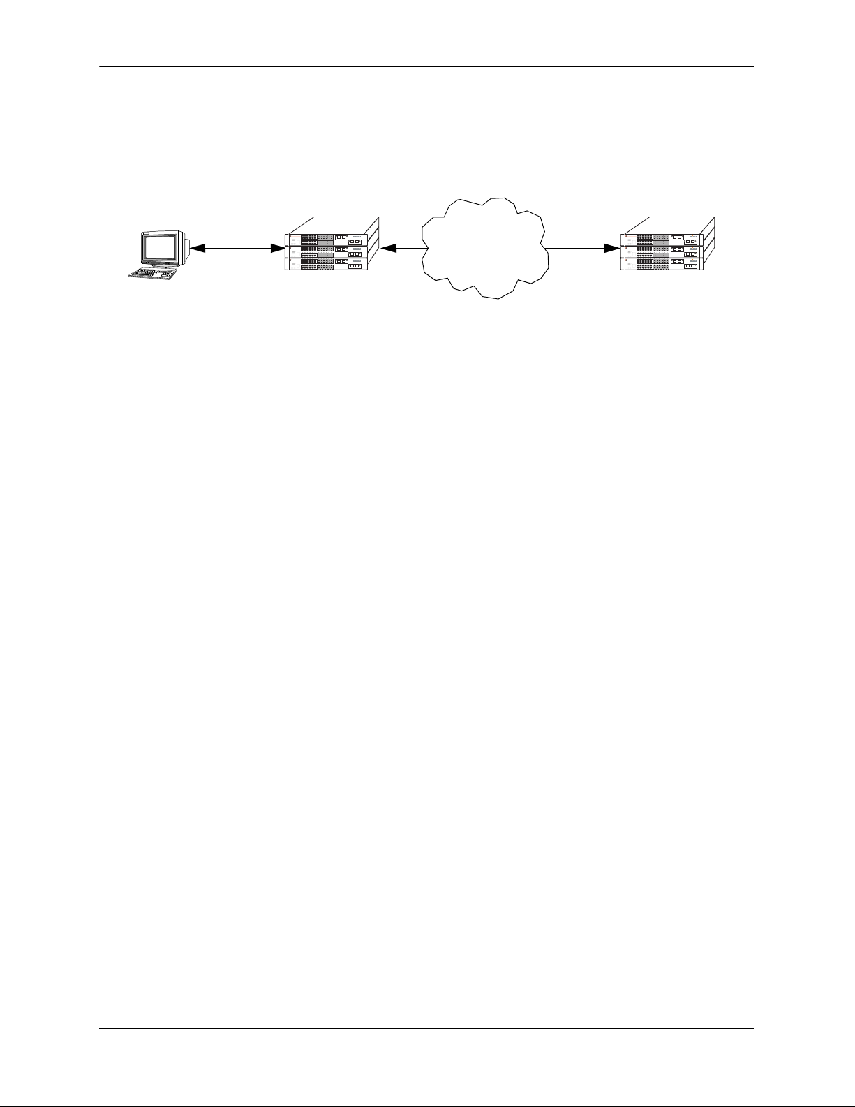
Using Secure Shell Logging Into the Switch
The following drawing shows an OmniSwitch, using IP address 11.233.10.145, establishing a Secure Shell
session across a network to another OmniSwitch, using IP address 11.333.30.135. To establish this session
from the console in the figure below, you would use the CLI commands shown in the examples above.
Once you issue the correct password, you are logged into the OmniSwitch at IP address 11.333.30.135.
Console
OmniSwitch 6648
OmniSwitch 6648
OmniSwitch 6648
OmniSwitch
11.233.10.145
Secure Shell Session between Two OmniSwitches
OmniSwitch 6648
OmniSwitch 6648
OmniSwitch 6648
OmniSwitch
11.333.30.135
page 1-12 OmniSwitch 6600 Family Switch Management Guide March 2005
Page 29

Logging Into the Switch Using Secure Shell
To view the parameters of the Secure Shell session, issue the who command. The following will display.
-> who
Session number = 0
User name = (at login),
Access type = console,
Access port = Local,
IP address = 0.0.0.0,
Read-only domains = None,
Read-only families = ,
Read-Write domains = None,
Read-Write families = ,
End-User profile =
Session number = 1
User name = rrlogin1,
Access type = ssh,
Access port = NI,
IP address = 11.233.10.145,
Read-only domains = None,
Read-only families = ,
Read-Write domains = All ,
Read-Write families = ,
End-User profile =
This display shows two sessions currently running on the remote OmniSwitch at IP address
11.333.30.135. Session number 0 is identified as the console session. Session number 1 indicates the
User name is rrlogin1, the IP address is 11.233.10.145, and the Access type is “ssh” which indicates a
Secure Shell session.
Closing a Secure Shell Session
To terminate the Secure Shell session, issue the exit command. The following will display:
-> exit
Connection to 11.333.30.135 closed.
Using the example shown above, this display indicates the Secure Shell session between the two switches
is closed. At this point, the user is logged into the local OmniSwitch at IP address 11.233.10.145.
Log Into the Switch with Secure Shell FTP
To open a Secure Shell FTP session from a local OmniSwitch to a remote device, proceed as follows:
1 Log on to the OmniSwitch and issue the sftp CLI command. The command syntax requires you to
identify the IP address for the device to which you are connecting. The following command establishes a
Secure Shell FTP interface from the local OmniSwitch to IP address 10.222.30.125.
-> sftp 10.222.30.125
login as:
2 You must have a login and password that is recognized by the IP address you specify. When you enter
your login, the device you are logging in to will request your password as shown here.
-> sftp 10.222.30.125
login as: rrlogin2
rrlogin2's password for keyboard-interactive method:
OmniSwitch 6600 Family Switch Management Guide March 2005 page 1-13
Page 30

Using Secure Shell Logging Into the Switch
3 After logging in, you will receive the sftp> prompt. You may enter a question mark (?) to view
available Secure Shell FTP commands and their definitions as shown here.
sftp>?
Available commands:
cd path Change remote directory to 'path'
lcd path Change local directory to 'path'
chmod mode path Change permissions of file 'path' to 'mode'
help Display this help text
get remote-path [local-path] Download file
lls [path]] Display local directory listing
ln oldpath newpath Symlink remote file
lmkdir path Create local directory
lpwd Print local working directory
ls [path] Display remote directory listing
mkdir path Create remote directory
put local-path [remote-path] Upload file
pwd Display remote working directory
exit Quit sftp
quit Quit sftp
rename oldpath newpath Rename remote file
rmdir path Remove remote directory
rm path Delete remote file
symlink oldpath newpath Symlink remote file
version Show SFTP version
? Synonym for help
Note. Although Secure Shell FTP has commands similar to the industry standard FTP, the underlying
protocol is different. See Chapter 2, “Managing System Files,” for a Secure Shell FTP application example.
Closing a Secure Shell FTP Session
To terminate the Secure Shell FTP session, issue the exit command. The following will display:
-> exit
Connection to 11.333.30.135 closed.
This display indicates the Secure Shell FTP session with IP address 11.333.20.135 is closed. The user is
now logged into the OmniSwitch as a local device with no active remote connection.
page 1-14 OmniSwitch 6600 Family Switch Management Guide March 2005
Page 31

Logging Into the Switch Modifying the Login Banner
Modifying the Login Banner
The Login Banner feature allows you to change the banner that displays whenever someone logs into the
switch. This feature can be used to display messages about user authorization and security. You can
display the same banner for all login sessions or you can implement different banners for different login
sessions. You can display a different banner for logins initiated by FTP sessions than for logins initiated
by a direct console or a Telnet connection. The default login message looks similar to the following:
login : user123
password :
Welcome to the Alcatel OmniSwitch 6000
Software Version 5.1 Development, September 2, 2002.
Copyright(c), 1994-2002 Alcatel Internetworking, Inc. All Rights reserved.
OmniSwitch(TM) is a trademark of Alcatel Internetworking, Inc. registered
in the United States Patent and Trademark Office.
Here is an example of a banner that has been changed:
login : user123
password :
Welcome to the Alcatel OmniSwitch 6000
Software Version 5.1 Development, September 2, 2002.
Copyright(c), 1994-2002 Alcatel Internetworking, Inc. All Rights reserved.
OmniSwitch(TM) is a trademark of Alcatel Internetworking, Inc. registered
in the United States Patent and Trademark Office.
********** LOGIN ALERT ************************
This switch is a secure device. Unauthorized
use of this switch will go on your permanent record.
Two steps are required to change the login banner. These steps are listed here:
• Create a text file that contains the banner you want to display in the switch’s /flash/switch directory.
• Enable the text file by entering the session banner CLI command followed by the filename.
To create the text file containing the banner text, you may use the vi text editor in the switch (See
Chapter 2, “Managing System Files,” for information about creating files directly on the switch.) This
method allows you to create the file in the /flash directory without leaving the CLI console session. You
can also create the text file using a text editing software package (such as MS Wordpad) and transfer the
file to the switch’s /flash directory. For more information about file transfers, see Chapter 2, “Managing
System Files.”
If you want the login banner in the text file to apply to FTP switch sessions, execute the following CLI
command where the text filename is firstbanner.txt.
-> session banner ftp /flash/firstbanner.txt
If you want the login banner in the text file to apply to CLI switch sessions, execute the following CLI
command where the text filename is secondbanner.txt.
-> session banner cli /flash/secondbanner.txt
The banner files must contain only ASCII characters and should bear the .txt extension. The switch will
not reproduce graphics or formatting contained in the file.
OmniSwitch 6600 Family Switch Management Guide March 2005 page 1-15
Page 32

Modifying the Login Banner Logging Into the Switch
Modifying the Text Display Before Login
By default, the switch does not display any text before the login prompt for any CLI session.
At initial bootup, the switch creates a pre_banner.txt file in the /flash directory. The file is empty and
may be edited to include text that you want to display before the login prompt.
For example:
Please supply your user name and password at the prompts.
login : user123
password :
In this example, the pre_banner.txt file has been modified with a text editor to include the Please supply
your user name and password at the prompts message.
The pre-banner text cannot be configured for FTP sessions.
To remove a text display before the login prompt, delete the pre_banner.txt file (it will be recreated at the
next bootup and will be empty), or modify the pre_banner.txt file.
page 1-16 OmniSwitch 6600 Family Switch Management Guide March 2005
Page 33

Logging Into the Switch Configuring Login Parameters
Configuring Login Parameters
You can set the number of times a user may attempt unsuccessfully to log in to the switch’s CLI by using
the session login-attempt command as follows:
-> session login-attempt 5
In this example, the user may attempt to log in to the CLI five (5) times unsuccessfully. If the user
attempts to log in the sixth time, the switch will break the TCP connection.
You may also set the length of time allowed for a successful login by using the session login-timeout
command as follows:
-> session login-timeout 20
In this example, the user must complete the login process within 20 seconds. This means that the time
between a user entering a login name and the switch processing a valid password must not exceed 20
seconds. If the timeout period is exceeded, the switch will break the TCP connection.
Configuring the Inactivity Timer
You can set the amount of time that a user must be inactive before the session times out. By default, the
timeout for each session type is 4 minutes. To change the setting, enter the session timeout command with
the type of session (cli, http, or ftp) and the desired number of minutes. In the following example, the CLI
timeout is changed from the default to 8 minutes.
-> session timeout cli 8
This command changes the inactivity timer for new CLI sessions to 8 minutes. Current CLI sessions are
not affected. In this example, current CLI sessions will be timed out after 4 minutes. (CLI sessions are
initiated through Telnet, Secure Shell, or through the switch console port.)
For information about connecting to the CLI through Telnet or Secure Shell, see “Using Telnet” on
page 1-6 and “Using Secure Shell” on page 1-8. For information about connecting to the CLI through the
console port, see your Getting Started Guide. For information about using the CLI in general, see
Chapter 5, “Using the CLI.”
The ftp option sets the timeout for FTP sessions. For example, to change the FTP timeout to 5 minutes,
enter the following command:
-> session timeout ftp 5
This command changes the timeout for new FTP sessions to 5 minutes. Current FTP sessions are not
affected. For more information about FTP sessions, see “Using FTP” on page 1-7.
The http option sets the timeout for WebView sessions. For example, to change the WebView inactivity
timer to 10 minutes, enter the following command:
-> session timeout http 10
In this example, any new WebView session will have a timeout of 10 minutes. Current WebView sessions
are not affected. For more information about WebView sessions, see Chapter 9, “Using WebView.”
OmniSwitch 6600 Family Switch Management Guide March 2005 page 1-17
Page 34

Enabling the DNS Resolver Logging Into the Switch
Enabling the DNS Resolver
A Domain Name System (DNS) resolver is an optional internet service that translates host names into IP
addresses. Every time you enter a host name when logging into the switch, a DNS service must look up the
name on a server and resolve the name to an IP address. You can configure up to three domain name servers that will be queried in turn to resolve the host name. If all servers are queried and none can resolve the
host name to an IP address, the DNS fails. If the DNS fails, you must either enter an IP address in place of
the host name or specify the necessary lookup tables on one of the specified servers.
Note. You do not need to enable the DNS resolver service unless you want to communicate with the
switch by using a host name. If you use an IP address rather than a host name, the DNS resolver service is
not needed.
You must perform three steps on the switch to enable the DNS resolver service.
1 Set the default domain name for DNS lookups with the ip domain-name CLI command.
-> ip domain-name mycompany1.com
2 Specify the IP addresses of up to three servers with the ip name-server CLI command. These servers
will be queried when a host lookup is requested.
-> ip name-server 189.202.191.14 189.202.191.15 189.255.19.1
3 Use the ip domain-lookup CLI command to enable the DNS resolver service.
-> ip domain-lookup
You can disable the DNS resolver by using the no ip domain-lookup command. For more information,
refer to the OmniSwitch CLI Reference Guide.
Verifying Login Settings
To display information about login sessions, use the following CLI commands.
who Displays all active login sessions (e.g., console, Telnet, FTP, HTTP,
Secure Shell, Secure Shell FTP).
whoami Displays the current user session.
show session config Displays session configuration information (e.g., default prompt, ban-
ner file name, inactivity timer, login timer, login attempts).
show dns Displays the current DNS resolver configuration and status
For more information about these commands, refer to the OmniSwitch CLI Reference Guide.
page 1-18 OmniSwitch 6600 Family Switch Management Guide March 2005
Page 35

2 Managing System Files
This chapter describes the several methods of transferring software files onto the OmniSwitch and how to
register those files for use by the switch. This chapter also describes several basic switch management
procedures and discusses the Command Line Interface (CLI) commands used.
• File Management (copy, edit, rename, remove, change, and display file attributes)
• Directory Management (create, copy, move, remove, rename, and display directory information)
• System Date and Time (set system clock)
CLI commands are used in the configuration examples; for more details about the syntax of commands,
see the OmniSwitch CLI Reference Guide.
In This Chapter
Configuration procedures described in this chapter include:
• “Loading Software onto the Switch” on page 2-19
• “Creating a File Directory on the Switch” on page 2-30
• “Registering Software Image Files” on page 2-26
• “Setting the System Clock” on page 2-35
For related information about connecting a terminal to the switch, see your Getting Started Guide. For
information about switch command privileges, see Chapter 8, “Managing Switch Security.”
OmniSwitch 6600 Family Switch Management Guide March 2005 page 2-1
Page 36

File Management Specifications Managing System Files
File Management Specifications
The following table lists specifications for the OmniSwitch flash directory and file system as well as the
system clock.
File Transfer Methods FTP, Zmodem
Switch Software Utility OmniSwitch as an FTP Client
Configuration Recovery The /flash/certified directory holds configurations that are certified as
the default start-up files for the switch. They will be used in the event of
a non-specified reload.
Switch /flash Directory
• 32 MB flash memory available for switch files and directories
• Contains the /certified and /working directories
File/Directory Name Metrics
File/Directory Name Characters Character types are limited to a-z, A-Z, 0-9, dashes (-), dots (.), and
Maximum Number of
Files/Directories
Sub-Directories Up to seven sub-directories allowed including /flash.
Text Editing Vi standard UNIX editor. The Ed standard UNIX editor is available in
System Clock Set local date, time and time zone, Universal Time Coordinate (UTC),
System Date Default Value THU JAN 01 1970 (Thursday, January 1, 1970)
• 32 characters maximum for directory and file names
• 255 character maximum for a fully qualified path
underlines (_)
Maximum of 244 files and/or directories allowed in the root (flash)
directory.
the debug mode.
Daylight Savings (DST or summertime).
page 2-2 OmniSwitch 6600 Family Switch Management Guide March 2005
Page 37

Managing System Files Switch Administration Overview
Switch Administration Overview
The OmniSwitch has a variety of software features designed for different networking environments and
applications. Over the life of the switch, it is very likely that your configuration and feature set will change
because the needs of your network are likely to expand. Also, software updates become available from
Alcatel. If you change your configuration to upgrade your network, you must understand how to install
switch files and to manage switch directories.
The OmniSwitch switch has 32 MB of usable flash memory. You can use this memory to store files,
including executable files (used to operate switch features and applications), configuration files, and log
files.
You need to understand the various methods of loading files onto the switch for software upgrades and
new features. Once the files are on the switch, the CLI has commands that allow you to load, copy, and
delete these files. The CLI also has commands for displaying, creating, and editing ASCII files directly on
the switch. You may also want to establish a file directory structure to help organize your files on the
switch.
All of the files and directories on the switch bear a time stamp. This is useful for switch administration
because the time stamp allows you to tell at a glance which files are the most recent. You can set the
system clock that controls these time stamps as well as other time based switch functions.
File Transfer
The switch can receive and send files using industry standard local and remote transfer methods. Each of
these methods are defined and explained. Because file transfers can involve logging onto the switch from
a remote host, security factors, such as DNS resolver and Authenticated Switch Access requirements
should be considered.
User’s Host
File Transfer from User’s
Host to the OmniSwitch
File Transfer to OmniSwitch
It is not enough to simply transfer a file onto the switch. Once files are on the switch, they must be
registered in order to become functional. The OmniSwitch has a directory structure that allows you to
install new software while maintaining a backup copy of your old configuration. This directory structure is
explained in the “Switch Directories” section on page 2-4 and instructions are given on how to execute the
install command in the “Registering Software Image Files” section on page 2-26.
OmniSwitch
OmniSwitch 6648
OmniSwitch 6600 Family Switch Management Guide March 2005 page 2-3
Page 38

Switch Administration Overview Managing System Files
Switch Directories
You can create your own directories in the switch flash directory. This allows you to organize your configuration and text files on the switch. You can also use the vi command to create files. This chapter tells you
how to make, copy, move, and delete both files and directories.
Listing Directory: /flash
Directory: /flash/certified
(Files)
Directory: /flash/working
Directory: /flash/network
(Files)
Switch Flash Directory
(Files)
(Files)
boot.params
cs_system.pmd
boot.slot.cfg
boot.cfg.1.err
swlog1.log
swlog2.log
page 2-4 OmniSwitch 6600 Family Switch Management Guide March 2005
Page 39

Managing System Files File and Directory Management
File and Directory Management
A number of CLI commands allow you to manage files on your switch by grouping them into subdirectories within the switch’s flash directory. These commands perform the same functions as file
management software applications (such as Microsoft’s Explorer) perform on a workstation. For
documentation purposes, we have categorized the commands into three groups.
• Directory commands allow you to create, copy, move, remove, rename, and display directories.
• File commands allow you copy, edit, rename, remove, change, and display file attributes.
• Utility commands display memory and system diagnostic information.
The following illustration represents a sample flash directory that contains three directories and six files at
the top level. The sample working directory and the certified directory both hold five files. The sample
network directory holds one file.This sample flash directory is used in the explanations of the directory,
file and utility CLI commands described in the following section.
Note. Your switch may show files and directories different from the ones shown in this example.
boot.params
cs_system.pmd
boot.slot.cfg
Working Directory
Hweb.img
Hsecu.img
Hbase.img
Hl2eth.img
boot.cfg.1.err
swlog1.log
boot.cfg
boot.params
Sample Flash Directory
Flash Files
swlog2.log
Network Directory
policy.cfg
Certified Directory
Hsecu.img
Hrelease.img
Hos.img
Hl2eth.img
boot.cfg
boot.params
OmniSwitch 6600 Family Switch Management Guide March 2005 page 2-5
Page 40

File and Directory Management Managing System Files
To list all files and directories in your current directory, use the ls command. Here is a sample display of
the flash directory.
-> ls
Listing Directory /flash:
drw 512 Oct 25 14:39 certified/
drw 512 Jul 15 14:59 NETWORK/
drw 512 Oct 25 14:17 WORKING/
-rw 321 Oct 25 14:39 boot.params
-rw 163258 Oct 2 11:04 cs_system.pmd
-rw 11 Jul 30 14:09 boot.slot.cfg
-rw 693 Oct 9 11:55 boot.cfg.1.err
-rw 0 Oct 28 11:14 swlog1.log
-rw 64000 Oct 28 15:51 swlog2.log
9467904 bytes free
The following information describes the screen displayed by the ls command.
• The first column consists of three text characters. The first character indicates whether the row entry is
a file (-) or a directory (d). The second and third characters indicate the user’s read/write permissions.
drw 512 Oct 25 14:17 WORKING/
-rw 321 Oct 25 14:39 boot.params
Here, the first entry shows a directory (d) for which the user has read and write (rw) permissions. The
second entry shows a file (-) for which the user has read and write (rw) permissions.
• The second column indicates the number of bytes of flash memory the row entry occupies.
drw 512 Oct 25 14:17 WORKING/
-rw 321 Oct 25 14:39 boot.params
Here, the first entry shows that the directory uses 512 bytes of flash memory. The second entry shows
that the file occupies 321 bytes of flash memory.
• The third, fourth and fifth columns show the date and time the row entry was created or copied into the
flash directory.
drw 512 Oct 25 14:17 WORKING/
-rw 321 Oct 25 14:39 boot.params
Here, the first entry indicates the file was created or copied on April 22 at 05:23 hours. The second
entry indicates that the directory was created or copied on April 19 at 06:12 hours.
• The column on the right lists the file or directory name. Note that directory names end with a slash (/)
character.
drw 512 Oct 25 14:17 WORKING/
-rw 321 Oct 25 14:39 boot.params
Here, the first entry shows a directory named WORKING, the second entry shows a file named
boot.params.
The value shown at the bottom of the display indicates the amount of flash memory remaining for use in
this directory (9.47 megabytes in the above example).
page 2-6 OmniSwitch 6600 Family Switch Management Guide March 2005
Page 41

Managing System Files File and Directory Management
Using Wildcards
Wildcards allow you to substitute symbols (* or ?) for text patterns while using file and directory
commands. The asterisk (*) takes the place of multiple characters and the question mark character (?)
takes the place of single characters. More than one wildcard can be used within a single text string.
Multiple Characters
An asterisk (*) is used as a wildcard for multiple characters in a text pattern. The following command will
list all entries in the current directory that end with the .log extension.
-> ls *.log
Listing Directory /flash:
-rw 64000 Sep 21 19:49 swlog1.log
-rw 64000 Aug 12 19:06 swlog2.log
The following command lists all entries in the current directory that contain the i character.
-> ls *i*
Listing Directory /flash:
drw 2048 Aug 21 17:49 certified/
drw 2048 Aug 12 18:51 working/
-rw 31 Jul 29 2001 policy.cfg
drw 2048 Jul 28 12:17 switch/
Single Characters
The question mark (?) is used as a wildcard for a single character in a text pattern. The following
command will locate all entries containing swlog followed by any single character, followed by the .log
extension.
-> ls swlog?.log
Listing Directory /flash:
-rw 64000 Jul 21 19:49 swlog1.log
-rw 64000 Aug 12 19:06 swlog2.log
The single and multiple character wildcards can be used in combination. The following command lists all
entries containing the letter i followed by any two single characters.
-> ls *i??
Listing Directory /flash:
drw 2048 Aug 12 18:51 working/
OmniSwitch 6600 Family Switch Management Guide March 2005 page 2-7
Page 42

File and Directory Management Managing System Files
Directory Commands
The directory commands are applied to the switch file system and to files contained within the file system.
When you first enter the flash directory, your login is located at the top of the directory tree. You may
navigate within this directory by using the pwd and cd commands (discussed below). The location of your
login within the directory structure is called your current directory. You need to observe your login
location because when you issue a command, that command applies only to directories and files in your
current directory unless another path is specified.
The following drawing is a logical representation of the file directory shown in the illustration on
page 2-5.
Flash Directory
Certified Directory
(Files)
Hsecu.img
Hos.img
H12eth.img
Hrelease.img
boot.cfg
Working Directory
(Files)
Hweb.imb
Hsecu.img
H12eth.img
Hbase.img
boot.cfg
Network Directory
(File)
policy.cfg
(Files)
boot.params
cs_system.pmd
boot.slot.cfg
boot.cfg.1.err
swlog.1.log
swlog2.log
Sample Switch Directory Tree
Determining Your Location in the File Structure
Use the pwd command to display the path to your current directory. When you first log into the switch,
your current directory is the flash directory. If you enter the pwd command, the following will display.
-> pwd
/flash
->
The display shows the name of the current directory and its path. If your current directory is the certified
directory and you enter the pwd command, the following will display.
-> pwd
/flash/certified
->
The display shows the path to your current directory.
page 2-8 OmniSwitch 6600 Family Switch Management Guide March 2005
Page 43

Managing System Files File and Directory Management
Changing Directories
Use the cd command to navigate within the file directory structure. The cd command allows you to move
“up” or “down” the directory tree. To go down, you must specify a directory located in your current directory. The following command example presumes your current directory is the /flash file directory as
shown in the directory on page 2-8 and that you want to move down the directory tree to the certified
directory.
->pwd
/flash
->cd certified
->
To verify that your current directory has changed to /flash/certified, use the pwd command and the
following will display.
->pwd
/flash/certified
To move “up” the directory tree, use the cd command. Enter cd.. (cd dot dot) without specifying a direc-
tory name and your current directory will move up one directory level. If you enter cd without the dots,
your current directory will move to the top of the tree. The following example shows the cd command
used where the current directory is /flash/certified.
->pwd
/flash/certified
-> cd
->
To verify that your current directory has moved up the directory tree, use the pwd command to display
your location. The display shows you have moved up one level from the /flash/certified directory and that
your current directory is /flash.
-> pwd
/flash
If you use the cd command while you are at the top of the directory tree, the cd command will have no
effect on the location of your login. In other words, if you use cd while your current directory is /flash,
your current directory will remain /flash after you execute the cd command.
OmniSwitch 6600 Family Switch Management Guide March 2005 page 2-9
Page 44

File and Directory Management Managing System Files
Displaying Directory Contents
The ls and dir commands have the same function. These two commands display the contents of the current
directory. If you use the ls or dir command while logged into the /flash file directory as shown on
page 2-8, the following will display.
-> dir
Listing Directory /flash:
drw 512 Oct 25 14:39 certified/
drw 512 Jul 15 14:59 NETWORK/
drw 512 Oct 25 14:17 WORKING/
-rw 321 Oct 25 14:39 boot.params
-rw 163258 Oct 2 11:04 cs_system.pmd
-rw 11 Jul 30 14:09 boot.slot.cfg
-rw 693 Oct 9 11:55 boot.cfg.1.err
-rw 0 Oct 28 11:14 swlog1.log
-rw 64000 Oct 29 09:12 swlog2.log
9467904 bytes free
If you specify a path as part of the ls or dir command, your screen will list the contents of the directory at
the specified path.
-> ls /flash/certified
Listing Directory /flash/certified:
drw 2048 Oct 12 11:16 ./
drw 2048 Oct 12 15:58 ../
-rw 2636 Oct 12 11:16 boot.cfg
-rw 496901 Oct 16 11:07 Hl2eth.img
-rw 860086 Oct 26 11:07 Hos.img
-rw 123574 Oct 14 10:54 Hsecu.img
-rw 123574 Oct 14 10:54 Hrelease.img
page 2-10 OmniSwitch 6600 Family Switch Management Guide March 2005
Page 45

Managing System Files File and Directory Management
Making a New Directory
To make a new directory use the mkdir command. You may specify a path for the new directory, otherwise, the new directory will be created in your current directory. The syntax for this command requires a
slash (/) and no space between the path and the new directory name. Also, a slash (/) is required at the
beginning of your path specification. The following command makes a new directory in the working
directory.
-> mkdir /flash/working/newdir1
Flash Directory
Working Directory
(Files)
Hweb.imb
Hsecu.img
Hl2eth.img
Hbase.img
boot.cfg
newdir1 Directory
This drawing represents the content of the /flash/working directory after the new directory is added.
Note. Your login account must have write privileges to execute the mkdir command.
OmniSwitch 6600 Family Switch Management Guide March 2005 page 2-11
Page 46

File and Directory Management Managing System Files
Displaying Directory Contents Including Subdirectories
The ls -r command displays the contents of your current directory in addition to recursively displaying all
subdirectories. The following example shows the result of the ls -r command where the /flash/working
directory contains a directory named newdir1. Be sure to include a space between ls and -r.
-> ls -r /flash/working
Listing Directory /flash/working:
drw 2048 Oct 14 17:14 ./
drw 2048 Oct 14 17:12 ../
drw 2048 Oct 14 17:14 newdir1/
-rw 2636 Oct 12 11:16 boot.cfg
-rw 123574 Oct 14 10:54 Hl2eth.img
-rw 123574 Oct 14 10:54 Hbase.img
-rw 123574 Oct 14 10:54 Hsecu.img
-rw 123574 Oct 14 10:54 Hweb.img
Listing Directory /flash/working/newdir:
drw 2048 Oct 14 17:14 ./
drw 2048 Oct 14 17:14 ../
Copying an Existing Directory
The cp -r command recursively copies directories, as well as any associated subdirectories and files.
Before using this command, you should make sure you have enough memory space in your target directory to hold the new material you are copying. In this example, a copy of the working directory and all its
contents will be created in the certified directory. The destination directory must exist before the cp -r
command will work.
->cp -r /flash/working flash/certified/working
Flash Directory
Working Directory
(Files)
boot.cfg
H12eth.img
Hbase.img
Hsecu.img
Hweb.img
newdir1 Directory
boot.cfg
H12eth.img
Hos.img
Hrelease.img
Hsecu.img
Certified Directory
(Files)
(Files)
boot.cfg
H12eth.img
Hbase.img
Hsecu.img
Hweb.img
Working Directory
newdir1 Directory
Note. Your login account must have write privileges to execute the cp -r command.
page 2-12 OmniSwitch 6600 Family Switch Management Guide March 2005
Page 47

Managing System Files File and Directory Management
To verify the creation of the new directory, use the ls -r command to produce a list of the contents of the
certified directory. This list will include the files that were originally in the certified directory plus the
newly created copy of the working directory and all its contents.
->ls -r /flash/certified
Listing Directory /flash/certified
drw 2048 Oct 12 16:22 ./
drw 2048 Oct 15 10:16 ../
-rw 4347 Oct 2 12:25 boot.cfg
-rw 683217 Oct 25 14:20 Hl2eth.img
-rw 844217 Oct 25 14:21 Hos.img
-rw 4658 Oct 25 14:21 Hrelease.img
-rw 193819 Oct 25 14:21 Hwebsecu.im
Listing Directory /flash/certified/working
drw 2048 Oct 14 17:14 ./
drw 2048 Oct 14 17:12 ../
drw 2048 Oct 14 17:14 newdir1/
-rw 4347 Oct 2 12:25 boot.cfg
-rw 1041935 Oct 25 14:17 Hweb.img
-rw 142830 Oct 25 14:17 Hsecu.img
-rw 2743945 Oct 25 14:16 Hbase.img
-rw 844217 Oct 25 14:17 Hos.img
Listing Directory /flash/certified/working/newdir:
drw 2048 Oct 14 17:14 ./
drw 2048 Oct 14 17:14 ../
Removing a Directory and its Contents
The rmdir command removes the specified directory and all its contents. If the following command is
issued from the flash directory, shown in the drawing on page 2-8, the working directory would be
removed from the certified directory.
->rm -r /flash/certified/working
Note. Your login account must have write privileges to execute the rmdir command.
OmniSwitch 6600 Family Switch Management Guide March 2005 page 2-13
Page 48

File and Directory Management Managing System Files
File Commands
The file commands apply to files located in the /flash file directory and its sub-directories.
Note. Each file in any directory must have a unique name. If you attempt to create or copy a file into a
directory where a file of the same name already exists, you will overwrite or destroy one of the files.
Creating or Modifying Files
The switch has an editor for creating or modifying files. The editor is invoked by entering the vi command
and the name of the new file or existing file that you want to modify. For example:
-> vi /flash/my_file
This command puts the switch in editor mode for my_file. If my_file does not already exist, the switch
will create the file in the flash directory. In editing mode, the switch uses command keystrokes similar to
any vi UNIX text editor. For example, to quit the edit session and save changes to the file, type ZZ to
return to the CLI prompt.
Copy an Existing File
Use the cp command to copy an existing file. You can specify the path and filename for the original file
being copied as well as the path and filename for the new copy being created. If no path is specified, the
command assumes the current directory. The following syntax copies the Hos.img file from the working
directory to the certified directory.
->cp /flash/working/Hos.img /flash/certified
This second example presumes that the user’s current directory is the /flash/working directory. Here, it is
not necessary to specify a path for the original file. A copy of Hos.img will appear in the /flash/certified
directory once the following command is executed.
->cp Fos.img /flash/certified
This third example presumes that the user’s current directory is the flash directory. To copy a file into the
same directory where the file currently exists, the user must specify a new filename. The following
command will result in the Hbase.img file being copied into the /flash/working directory under the new
name of newfile.img. Both Hos.img and its copy newfile.img will appear in the /flash/working directory.
->cp /flash/working/Hbase.img newfile.img
In these examples, a new file will be written to the specified or assumed path with the new filename. If
you do not specify a new filename, the new file will have the same name as the copied file. If you copy a
file to its own directory, you must specify a new filename. In each case, the file being copied will remain
in its original location.
Note. You must have write privileges in order to execute the cp command.
page 2-14 OmniSwitch 6600 Family Switch Management Guide March 2005
Page 49

Managing System Files File and Directory Management
Move an Existing File or Directory
The move and mv commands have the same function and use the same syntax. Use these commands to
move an existing file or directory to another location. You can specify the path and name for the file or
directory being moved. If no path is specified, the command assumes the current path. You can also
specify a path and a new name for the file or directory being moved. If no name is specified, the existing
name will be used.
Note. Your login account must have write privileges to use the move or mv command.
Flash Directory
Certified Directory
(Files)
Working Directory
(Files)
Network Directory
(File)
policy.cfg
Testfiles Directo r y
(File)
testfile2
In this first example, the user’s current directory is the flash directory. The following command syntax
moves the testfile2 file from the user created testfiles directory into the working directory as shown in the
illustration above. The screen displays a warning that the file is being renamed (or in this case, redirected).
-> move /flash/testfiles/testfile2 /flash/working/testfile2
WARNING:renaming file /flash/testfiles/testfile2 -> /flash/working/testfile2
In the next example, the user’s current directory is the /flash/testfiles directory as shown in the illustration,
so it is not necessary to specify a path for the file being copied. However, the command syntax specifies a
path to the destination directory. The screen displays a warning that the file is being renamed.
-> move testfile2 /flash/working/newtestfile2
WARNING:renaming file /flash/working/newtestfile2 -> /flash/working/newtestfile2
In this third example, the user’s current directory is the flash directory. Here, it is not necessary to specify
a path for the destination file but a path must be specified for the original file. The screen displays a
warning that the file is being renamed.
-> move /flash/testfiles/testfile2 newfile2
WARNING: renaming file /flash/testfiles/testfile2 -> /flash/testfiles/newfile2
In each of the above examples, a new file will be written to the specified or assumed path with the new
filename. In each case, the file being copied will be removed from its original location.
OmniSwitch 6600 Family Switch Management Guide March 2005 page 2-15
Page 50

File and Directory Management Managing System Files
Change File Attribute and Permissions
The chmod and attrib commands have the same function and use the same syntax. Use these commands
to change read-write privileges for the specified file. The following syntax sets the privilege for the
config1.txt file to read-write. In this example, the user’s current directory is the /flash file directory.
Note. You must have read-write privileges to a file to change that file’s privileges.
To set the permission for the config1.txt file to read-only, use the following syntax.
-> chmod -w /flash/config1.txt
To set the permission for the config1.txt file to read/write, use the following syntax.
-> chmod +w /flash/config1.txt
Delete an Existing File
The delete command deletes an existing file. If you use the delete command from the directory containing
the file, you do not need to specify a path. If you are in another directory, you must specify the path and
name for the file being deleted. The user of this command must have write privileges for any file being
deleted.
-> delete /flash/config.txt
Managing Files on Non Primary Switches
You can copy a file from a non primary switch to the primary switch in a stack with the rcp command. To
use this command enter rcp followed the slot number of the non primary switch, the path and file name of
the source file on the non primary switch, and the destination file name on the primary switch.
For example, to copy the boot.params file the /flash directory on Switch 4 in a stack to the primary
switch and name it boot.params.bak enter:
-> rcp 4 /flash/boot.params boot.params.bak
To delete a file on a non primary switch use the rrm command. To use this command enter rrm followed
by the slot number of the non primary switch and the path and file name of the file on the non primary
switch to be deleted.
For example, to delete the boot.params file in the /flash directory on Switch 4 enter:
-> rrm 4 /flash/boot.params
To list the directory contents of a non primary switch use the rls command by entering rls followed by the
slot number of the non primary switch and the path name of the directory you want to display. (As an
option, you can also specify a specific file name to be displayed.)
For example, to display the contents of the /working directory on Switch 4 enter:
-> rls 4 /working
page 2-16 OmniSwitch 6600 Family Switch Management Guide March 2005
Page 51

Managing System Files File and Directory Management
A screen similar to the following will be displayed:
drw 512 Mar 9 17:19 ./
drw 512 Mar 9 17:20 ../
-rw 3555972 Mar 9 06:58 Hbase.img
-rw 266815 Mar 9 06:57 Hadvrout.img
-rw 113389 Mar 9 06:58 Hdiag.img
-rw 1297834 Mar 9 06:58 Heni.img
-rw 791455 Mar 9 06:58 Hl2eth.img
-rw 878029 Mar 9 06:58 Hos.img
-rw 277136 Mar 9 06:58 Hqos.img
-rw 8215 Mar 9 07:01 Hrelease.img
-rw 463498 Mar 9 06:58 Hrout.img
-rw 130556 Mar 9 06:58 Hsecu.img
-rw 1305435 Mar 9 17:18 Hweb.img
-rw 267186 Mar 9 06:58 Hwebl2eth.img
-rw 242646 Mar 9 06:58 Hwebqos.img
-rw 145175 Mar 9 06:58 Hwebrout.img
-rw 205762 Mar 9 06:58 Hwebsecu.img
-rw 68559 Mar 9 06:58 Hwebadvrout.img
-rw 16730 Feb 27 13:21 boot.cfg
-rw 105613 Feb 26 15:54 certs.pem
-rw 105613 Feb 26 15:54 certs.pem.bak
Utility Commands
The utility commands include freespace, fsck, and newfs. These commands are used to check memory
and delete groups of files.
Displaying Free Memory Space
The freespace command displays the amount of free memory space available for use in the switch’s file
system. You may issue this command from any location in the switch’s directory tree.
-> freespace
/flash 16480256 bytes free
Performing a File System Check
The fsck command performs a file system check and can automatically repair any errors found. It displays
diagnostic information in the event of file corruption. When you enter the command, you must specify the
flash directory as follows.
-> fsck /flash
The screen displays the following prompt:
Do you want fsck to automatically repair any errors found? (<CR> = No)
OmniSwitch 6600 Family Switch Management Guide March 2005 page 2-17
Page 52

File and Directory Management Managing System Files
Press Enter to skip repairing files, or enter yes to start file repair. If you enter yes, the screen displays similar to the following:
/flash/ - disk check in progress ...
/flash/ - Volume is OK
total # of clusters: 14,773
# of free clusters: 9,621
# of bad clusters: 0
total free space: 19,242 Kb
max contiguous free space: 7,454,720 bytes
# of files: 28
# of folders: 4
total bytes in files: 10,262 Kb
# of lost chains: 0
total bytes in lost chains: 0
Deleting the Entire File System
The newfs command deletes the flash file system and all the files and directories contained in it. This
command is used when you want to reload all files in the file system.
Caution. This command will delete all of the switch’s system files. All configurations programmed into
the switch will be lost. Do not use this command unless you are prepared to reload all files.
page 2-18 OmniSwitch 6600 Family Switch Management Guide March 2005
Page 53

Managing System Files Loading Software onto the Switch
Loading Software onto the Switch
There are three common methods for loading software to and from your switch. The method you use
depends on your workstation software, your hardware configuration, and the location and condition of
your switch. These methods are discussed here.
• FTP Server—You can use the switch as an FTP server. If you have FTP client software on your work-
station, you can transfer a file to the switch via FTP. This is normally done to load or upgrade the
switch’s software or configurations. For details see “Using the Switch as an FTP Server” on page 2-19.
• FTP Client—You can use the switch as an FTP client by connecting a terminal to the switch’s console
port and using standard FTP commands. This feature is useful in cases where you do not have access to
a workstation with an FTP client. For details see “Using the Switch as an FTP Client” on page 2-21.
• Zmodem—You can load software directly through the serial port with any terminal emulator that
supports the Zmodem protocol. Note that a Zmodem transfer of large files may take several minutes to
complete. For details see “Using Zmodem” on page 2-24.
Using the Switch as an FTP Server
The switch can act as an FTP server for receiving files transferred from your workstation. You can transfer software files to the switch using standard FTP client software located on a host workstation. This is
normally done to load or upgrade the switch software.
Workstation
The FTP Client software
on the Workstation sends a
file from the Workstation to
the OmniSwitch
FTP Client FTP Server
OmniSwitch
OmniSwitch 6648
OmniSwitch FTP Server
The following describes how to transfer files where the switch is acting as an FTP server.
1 Log into the switch. Use your workstation’s FTP client software just as you would with any FTP
application. To log in to the switch, start your FTP client. Where the FTP client asks for “Name”, enter the
IP address of your switch. Where the FTP client asks for “User ID”, enter the username of your login
account on the switch. Where the FTP client asks for “Password”, enter your switch password.
Note. If you are using Authenticated Switch Access (ASA), the port interface must be authenticated for
FTP use and the username profile must have permission to use FTP. Otherwise the switch will not accept
an FTP login. For information about ASA, refer to the “Managing Switch Security” chapter in the Switch
Management Guide.
2 Specify the transfer mode. If you are transferring a switch image file, you must specify the binary
transfer mode on your FTP client. If you are transferring a configuration file, you must specify the ASCII
transfer mode.
OmniSwitch 6600 Family Switch Management Guide March 2005 page 2-19
Page 54

Loading Software onto the Switch Managing System Files
3 Transfer the file. Use the FTP “put” command or click the client’s download button to send the file to
the switch.
When you use FTP to transfer a file to the switch, the file is automatically placed in the switch’s /flash/
working directory. For details, on using CLI commands to managing files once they are on the switch see
“File and Directory Management” on page 2-5.
Note. You must use the binary mode (bin) to transfer files via FTP.
page 2-20 OmniSwitch 6600 Family Switch Management Guide March 2005
Page 55

Managing System Files Loading Software onto the Switch
Using the Switch as an FTP Client
Using the switch as an FTP client is useful in cases where you do not have access to a workstation with an
FTP client. You can establish an FTP session locally by connecting a terminal to the switch console port.
You can also establish an FTP session to a remote switch by using a Telnet session. Once you are logged
into the switch as an FTP client, you can use standard FTP commands.
Note. If you are using Authenticated Switch Access (ASA), the port interface must be authenticated for
FTP and Telnet use. The login profile must also have permission to use FTP. Otherwise the switch will not
accept an FTP login. For information about ASA and user privileges, refer to the “Managing Switch Security” chapter of this manual.
Terminal
A dumb terminal uses the FTP client on the OmniSwitch to retrieve
a file from a file server
OmniSwitch
File Server
OmniSwitch 6648
FTP Client FTP Server
OmniSwitch FTP Client
Use the switch ftp command to start its FTP client.
1 Establish a connection to the switch as explained in your Getting Started Guide
2 Log on to the switch and enter the ftp command to start the FTP client. Next, enter a valid host name
or IP address. (For information about enabling the DNS resolver for host names, please refer to Chapter 1,
“Logging Into the Switch.”) A screen similar to the following displays:
Connecting to [198.23.9.101]...connected
220 cosmo FTP server (UNIX(r) System V Release 4.1) ready
Name :
Note. You can only use a host name instead of an IP address if the DNS resolver has been configured and
enabled. If not, you must specify an IP address.
3 Set the client to binary mode with the bin command. Enter a valid user name and password for the host
you specified with the ftp command. A screen similar to the following displays:
Name : Jsmith
331 Password required for Jsmith
Password: *****
230 User Jsmith logged in.
OmniSwitch 6600 Family Switch Management Guide March 2005 page 2-21
Page 56

Loading Software onto the Switch Managing System Files
4 After logging in, you will receive the ftp-> prompt. You may enter a question mark (?) to view
available FTP commands as shown here.
ftp->?
Supported commands:
ascii binary bye cd delete
dir get help hash ls
put pwd quit remotehelp user
lpwd mput mget prompt !ls
lcd user
These are industry standard FTP commands. Their definitions are given in the following table.
ascii Set transfer type to ASCII (7-bit).
binary Set transfer type to binary (8-bit).
bye Close session gracefully.
cd Change to a new directory on the remote machine.
delete Delete a file on the remote machine.
dir Obtain a long listing on the remote machine.
get Retrieve a file from the remote machine.
hash Print the hash symbol (#) for every block of data transferred. (This com-
mand toggles hash enabling and disabling.)
help Displays a list of FTP commands and their definitions.
ls Display summary listing of the current directory on the remote host.
put Send a file to the remote machine.
pwd Display the current working directory on the remote host.
quit Close session gracefully.
remotehelp List the commands that the remote FTP server supports.
user Send new user information.
lpwd Display the current working directory on the local host.
mput Allows for the transfer of multiple files out of the local machine.
mget Allows for the transfer of multiple files into the local machine.
prompt Toggles the query for use with the mput and mget commands.
!ls Lists the contents (files and directories) of the local directory.
lcd Change to a new local directory
user Sends new user information.
If you lose communications while running FTP, you may receive a message similar to the following:
Waiting for reply (Hit ^C to abort)...........
In this case you can press Crtl-C to abort the session or wait until the communication failure is resolved
and the FTP transfer can continue.
Note. You must use the binary mode (bin) to transfer files via FTP.
page 2-22 OmniSwitch 6600 Family Switch Management Guide March 2005
Page 57

Managing System Files Loading Software onto the Switch
Using Secure Shell FTP
1 Log on to the OmniSwitch and issue the sftp CLI command. The command syntax requires you to
identify the IP address for the device you are connecting to. The following command establishes a Secure
Shell FTP interface from the local OmniSwitch to IP address 10.222.30.125.
-> sftp 10.222.30.125
login as:
2 You must have a login and password that is recognized by the IP address you specify. When you enter
your login, the device you are logging in to will request your password as shown here.
-> sftp 10.222.30.125
login as: rrlogin2
rrlogin2's password for keyboard-interactive method:
3 After logging in, you will receive the sftp> prompt. You may enter a question mark (?) to view
available Secure Shell FTP commands and their definitions as shown here.
sftp>?
Available commands:
cd path Change remote directory to 'path'
lcd path Change local directory to 'path'
chmod mode path Change permissions of file 'path' to 'mode'
help Display this help text
get remote-path [local-path] Download file
lls [path]] Display local directory listing
ln oldpath newpath Symlink remote file
lmkdir path Create local directory
lpwd Print local working directory
ls [path] Display remote directory listing
mkdir path Create remote directory
put local-path [remote-path] Upload file
pwd Display remote working directory
exit Quit sftp
quit Quit sftp
rename oldpath newpath Rename remote file
rmdir path Remove remote directory
rm path Delete remote file
symlink oldpath newpath Symlink remote file
version Show SFTP version
? Synonym for help
Note. Although Secure Shell FTP has commands similar to the industry standard FTP, the underlying
protocol is different.
Closing a Secure Shell FTP Session
To terminate the Secure Shell FTP session, issue the exit command. The following will display:
-> exit
Connection to 11.333.30.135 closed.
This display indicates the Secure Shell FTP session with IP address 11.333.20.135 is closed. The user is
now logged into the OmniSwitch as a local device with no active remote connection.
OmniSwitch 6600 Family Switch Management Guide March 2005 page 2-23
Page 58

Loading Software onto the Switch Managing System Files
Using Zmodem
A Zmodem application has been included with your switch software so that new programs and archives
can be uploaded through the switch’s serial console port. There are generally two situations that would
require you to use the switch’s console serial port to load software using Zmodem.
• Your system is having problems and the FTP transfer method does not work.
• The switch’s Ethernet Management port is either not functioning or not configured.
To use Zmodem, you must have a terminal emulator that supports the Zmodem protocol. There are many
Zmodem products available that operate differently. You should consult the user manual that came with
your terminal emulation software for details.
Note. If a file you are transferring already exists in the switch’s flash memory, you must remove the file
before transferring the new file via Zmodem.
Workstation
Zmodem
Zmodem is used to transfer
a file from a workstation to
the OmniSwitch
OmniSwitch
OmniSwitch 6648
Zmodem File Transfer
To transfer a file via Zmodem, complete the following steps.
1 Connect your terminal emulation device containing the Zmodem protocol to the switch’s console port.
2 Start the Zmodem process on your switch by executing the rz command.
-> rz
A screen similar to the following will appear.
Upload directory: /flash
rz ready to receive file, please start upload (or send 5 CTRL-X’s to abort).
**B000000023be50
3 Transfer the files using your terminal emulation software. The following will display.
ZMODEM file transfer successful,
Hit <RETURN> to exit...
When the transfer is complete, you can use the ls command to verify that the new files were loaded
successfully. To abort a Zmodem session enter Ctrl-X five times in succession.
page 2-24 OmniSwitch 6600 Family Switch Management Guide March 2005
Page 59

Managing System Files Loading Software onto the Switch
Note. Files transferred via Zmodem are loaded into the flash directory. Before the new files can be used
by the switch, you must transfer them to the switch’s /flash/working directory and execute the install
command.
OmniSwitch 6600 Family Switch Management Guide March 2005 page 2-25
Page 60

Registering Software Image Files Managing System Files
Registering Software Image Files
New software transferred to the switch must go through a registration process before it can be used by the
switch. The registration process includes two tasks.
• Transfer the new software file(s) to the switch’s /flash/working directory via remote connection.
• Register the software by executing the install command.
Note. Switch software must be located in the switch’s /flash/working directory before the install command
is executed.
Directories on the Switch
When you log into the switch, your current directory is the flash directory. For a factory default switch, the
flash directory contains three sub-directories and several files. It is important to understand the relationship of these directories before you load software or edit any of the files. The three directories are
described here:
• Certified directory—This directory contains configuration files that are certified as the default start-
up files for the switch. These are the trusted configuration and binary image files. They will be used in
the event of a non-specified reload. Do not attempt to edit these files. The path to this directory is
/flash/certified.
• Working directory—The working directory is a repository for configuration files that you are work-
ing on. If you are working on configuration files to develop a custom switch application, you may want
to test them before certifying them as the switch’s default. To do this, you can boot from the files in the
working directory while preserving the files in the certified directory. When the files in the working
directory are tested and working properly, you may certify them as the switch’s default files. The files
are then copied into the certified directory to replace the old ones. The path to this directory is
/flash/working.
• Network directory—This directory holds files that may be required by servers used for authentica-
tion. Other files can be put into this directory if desired. The path to this directory is /flash/network.
For more information on switch directories refer to the “Managing CMM Directory Content” chapter of
this manual.
page 2-26 OmniSwitch 6600 Family Switch Management Guide March 2005
Page 61

Managing System Files Registering Software Image Files
Using the Install Command
The install command verifies that the version number of the new file is compatible with files already on
the switch. It will also perform installation procedures required by the new file or the switch. Once these
procedures are completed, the install command will update the appropriate switch files so the newly registered file can be used. The new software must be loaded into the working directory of the switch in order
for the install command to work.
To register an image file that has been loaded into the switch’s working directory, enter the following
command along with the name of the file being registered:
-> install Hos.img
In this example, Hos.img is the name of the file being registered.
Note. You can use wildcards with the install command. For example to install all image files in the current
directory, use the following command:
-> install *.img
For more information, refer to “Using Wildcards” on page 2-7.
Executing the install command adds comments to the “Release” archive and package name; in addition,
version numbers are updated in the “Release” archive.
When the install command is executed it will perform a set of default operations to ensure version
compatibility. If the registration can not succeed without intervention or if there is a compatibility problem, the registration will be aborted and an error message will display.
Note. All registration processes take place within the working directory of the switch. New files are never
directly written to the certified directory. It is possible to perform registration procedures in the working
directory even if the switch is running off the files in the working directory. If the switch is booted using
files in the certified directory, no immediate effect from the registration will be realized until the system is
restarted from the working directory. If the system was booted from the working directory, the new software will be immediately available for use by the system following the successful completion of the registration process.
OmniSwitch 6600 Family Switch Management Guide March 2005 page 2-27
Page 62

Registering Software Image Files Managing System Files
Available Image Files
The following table is a list of image files available for the OmniSwitch 6600 Family. Most of the files
listed here are part of the base switch configuration. Files that support an optional switch feature are noted
in the table.
Archive File Name Base or Optional Software Description
Hadvrout.img Advanced Routing Advanced Routing
Hbase.img Base Software Base Software
Hdiag.img Base Software Diagnostics
Heni.img Base Software Ethernet Images
Hl2eth.img Base Software Layer 2 and Ethernet drivers
Hos.img Base Software Operating System
Hqos.img Base Software Quality of Service
Hrout.img Base Software Routing
Hsecu.img Optional Security Security (AVLANS)
Hweb.img Base Software Webview—Main
Hwebadvrout.img Advanced Routing Webview—Advanced Routing
Hwebl2eth.img Base Software Webview—Layer 2 and Ethernet drivers
Hwebqos.img Base Software Webview—Quality of Service
Hwebrout.img Base Software Webview—Routing
Hwebsecu.img Optional Security Webview—Security
Hrelease.img Base Software Release Archive
page 2-28 OmniSwitch 6600 Family Switch Management Guide March 2005
Page 63

Managing System Files Application Examples for File Management
Application Examples for File Management
The following sections give detailed examples of managing files and directories on the switch.
Transferring a File to the Switch Using FTP
In this example, the user is adding the AVLAN security feature to the switch. To do this the user must
load the Hsecu.img image file onto the switch and then register the file using the CLI install command.
The following steps describe how to transfer the file from the user workstation to the switch using an FTP
client on the workstation.
1 Load the Hsecu.img file onto a workstation that contains an FTP client.
You will normally receive the file from the Internet, via Email, or on CD media. Place the file on your
workstation where it can be easily downloaded.
2 Run the FTP client software on your workstation.
Most workstations have an FTP client installed. Refer to your manufacturer’s instructions for details on
running the FTP application.
3 Log in to the switch from your FTP client.
Where the FTP client asks for Name, enter the IP address of your switch. Where the FTP client asks for
User ID, enter “admin”. Where the FTP client asks for Password, enter “switch” or your custom configured password.
4 Transfer the file from the workstation to the switch using the FTP client.
If you have a GUI FTP client, select the Hsecu.img file on your desktop and click the download button. If
you have a text only FTP client, use the FTP “put” command to move the file from your desktop to the
switch. In either case, you must specify a binary file transfer because the Hsecu.img file is a binary file.
Once the transfer is complete, the file will appear in the switch’s /flash/working directory.
5 Close the FTP session with the switch.
6 To verify that the Hsecu.img file is in the /flash/working directory on the switch. Log onto the switch
and list the files in the /flash/working directory.
-> ls /flash/working
Listing Directory /flash/working:
drw 2048 Aug 4 10:45 ./
drw 2048 Aug 5 14:05 ../
-rw 670979 Aug 5 14:44 Hsecu.img
-rw 2877570 Aug 4 10:33 Hbase.img
-rw 217119 Aug 4 10:33 Hdiag.img
-rw 727663 Aug 4 10:33 Heni.img
-rw 236713 Aug 4 10:34 Hqos.img
-rw 5519 Aug 4 10:34 Hrelease.img
-rw 467850 Aug 4 10:34 Hrout.img
-rw 880 Sep 31 13:05 boot.cfg
This list verifies that the file is located on the switch in the /flash/working directory.
7 Execute the install command to register the security file Hsecu.img. The following will display:
OmniSwitch 6600 Family Switch Management Guide March 2005 page 2-29
Page 64

Application Examples for File Management Managing System Files
-> install Hsecu.img
renaming file temp.img -> /flash/working/Hrelease.img
Installation of Hsecu.img was successful.
The features and services supported by the Hsecu.img image file are now available on the switch.
Creating a File Directory on the Switch
In this example, the user wants to store several test files on the switch for use at a later date. The user has
loaded the files into the switch’s /flash/working directory using FTP. Rather than leaving the files in the
working directory, the user may want to create a new directory. The following steps describe how to create
a directory on the switch, how to transfer files into the directory, and how to list the files.
1 Log onto the switch and use the mkdir command to create a new directory called “resources”.
-> mkdir resources
->
2 Verify that the new directory was created by using the ls command. The “resources” directory is listed.
-> ls
Listing Directory /flash:
-rw 308 Aug 12 13:33 boot.params
drw 2048 Aug 14 10:45 certified/
drw 2048 Aug 15 16:24 working/
-rw 64000 Aug 15 16:19 swlog1.log
-rw 64000 Aug 15 14:05 swlog2.log
drw 2048 Sep 24 07:57 switch/
-rw 30 Aug 19 2023 policy.cfg
drw 2048 Aug 25 16:25 resources/
-rw 0 Sep 24 08:00 boot.cfg
3 Use the ls command to list the contents of the /flash/working directory.
-> ls /flash/working
Listing Directory /flash/working:
drw 2048 Aug 5 17:03 ./
drw 2048 Aug 5 16:25 ../
-rw 880 Sep 31 13:05 boot.cfg
-rw 6 Aug 5 17:03 test1.txt
-rw 6 Aug 5 17:03 test2.txt
-rw 6 Aug 5 17:03 test3.txt
4 Use the mv command to move the test files from /flash/working to /flash/resources.
-> mv test1.txt /flash/resources
-> mv test2.txt /flash/resources
-> mv test3.txt /flash/resources
page 2-30 OmniSwitch 6600 Family Switch Management Guide March 2005
Page 65

Managing System Files Application Examples for File Management
5 Use the ls command to verify that the files are now located in the /flash/resources directory.
-> ls /flash/resources
Listing Directory /flash/resources:
drw 2048 Jul 5 17:20 ./
drw 2048 Jul 5 16:25 ../
-rw 6 Jul 5 17:03 test1.txt
-rw 6 Jul 5 17:03 test2.txt
-rw 6 Jul 5 17:03 test3.txt
17995776 bytes free
FTP Client Application Example
The following example shows how to transfer a file named rrtext.txt from the switch’s /flash/working
directory to another host using the switch as an FTP client.
1 Log into the switch. Use the ls command to verify that your current directory is /flash.
-> ls
Listing Directory /flash:
-rw 272 Jun 12 15:57 boot.params
drw 2048 Jun 12 17:52 certified/
drw 2048 Jun 13 12:32 working/
drw 2048 Jul 12 16:22 switch/
-rw 10000 Jun 12 15:58 swlog1.log
-rw 10000 Jun 12 17:50 swlog2.log
-rw 445 Jun 21 11:43 aaasnap
-rw 7298 Jul 24 16:51 websnap1024
-rw 2662306 Jun 28 16:44 cs_system.pmd
-rw 543 Jun 28 12:02 aaapublic
drw 2048 Jun 28 17:50 newdir/
-rw 1452 Jun 29 12:50 nssnap76
-rw 1452 Jun 29 12:42 iesnap76
16480256 bytes free
2 Use the cd command to change your current directory to /flash/working. Use the ls or pwd command
to verify.
-> cd working
-> ls
Listing Directory /flash/working:
drw 2048 Aug 3 12:32 ./
drw 2048 Aug 14 10:58 ../
-rw 450 Aug 13 10:02 rrtest1.txt
OmniSwitch 6600 Family Switch Management Guide March 2005 page 2-31
Page 66

Application Examples for File Management Managing System Files
3 Enter the FTP mode by using the ftp command followed by the IP address or the name of the host you
are connecting to. (If you enter a host name, please refer to “Using Zmodem” on page 2-24.)
->ftp 10.255.11.101
220 Connecting to [10.255.11.101]...connected.
Cosmo Windows FTP server ready
Name : Myhost1
Note. You can only use a host name instead of an IP address if the DNS resolver has been configured and
enabled. If not, you must specify an IP address.
4 Enter a valid user name and password for the host you specified with the ftp command. A screen
similar to the following displays:
Name (d) : Jsmith
331 Password required for Jsmith
Password: *****
230 User Jsmith logged in.
5 Use the FTP “put” command to transfer the file from your switch to the host as shown here.
ftp> put rrtest.txt
The following will display.
200 Port set okay
150 Opening BINARY mode data connection
Transferred 20 octets in 1 seconds.
226 Transfer complete
ftp>
6 To exit the switch’s FTP client mode, use the “quit” FTP command. Your current directory on the
switch is /flash/working, which is the location from which you initiated the FTP client session. Use the
pwd CLI command to verify your current directory.
ftp> quit
221 Bye
-> pwd
/flash/working
Creating a File Directory Using Secure Shell FTP
The following example describes the steps necessary to create a directory on a remote OmniSwitch and to
transfer a file into the new directory using Secure Shell FTP.
1 Log on to the switch and issue the sftp CLI command with the IP address for the device you are
connecting to. The following command establishes a Secure Shell FTP interface from the local
OmniSwitch to another OmniSwitch at IP address 10.222.30.125.
-> sftp 10.222.30.125
login as:
page 2-32 OmniSwitch 6600 Family Switch Management Guide March 2005
Page 67

Managing System Files Application Examples for File Management
2 You must have a login and password that is recognized by the IP address you are logging in to. When
you enter your login, the device will request your password. Here, the login “rrlogin2” is used, the system
requests a password.
-> sftp 10.222.30.125
login as: rrlogin2
rrlogin2's password for keyboard-interactive method:
Once the correct password is given and the login is completed, the sftp> prompt displays. This indicates
that you are in the Secure Shell FTP mode and must therefore use the Secure Shell FTP commands as
listed on page 2-23
.
3 Use the ls command to display the contents of the target OmniSwitch’s directory.
sftp> ls
287 boot.params
2048 certified
2048 working
64000 swlog1.log
64000 swlog2.log30 policy.cfg
2048 network
206093 cs_system.pmd
2048 LPS
256 random-seed
4 Use the mkdir command to create a new directory entitled “newssdir” in the target OmniSwitch.
Remember you must specify the path for the new directory as follows:
sftp> mkdir /flash/newssdir
5 Use the ls command again to list the contents of the current (flash) directory. Note that the “newssdir”
directory appears toward the bottom of the following list.
sftp> ls
287 boot.params
2048 certified
2048 working
64000 swlog1.log
64000 swlog2.log30 policy.cfg
2048 network
206093 cs_system.pmd
2048 LPS
2048 newssdir
256 random-seed
OmniSwitch 6600 Family Switch Management Guide March 2005 page 2-33
Page 68

Verifying Directory Contents Managing System Files
Transfer a File Using Secure Shell FTP
To demonstrate how to transfer a file using the Secure Shell FTP, this application example continues from
the previous example, where a new directory named “newssdir” was created on a remote OmniSwitch.
1 Use the Secure Shell FTP put command to transfer the file “testfile1.rr” from the local OmniSwitch to
the “newssdir” directory on the remote OmniSwitch. You must specify the local path (where the file
originates) and the remote path (where the file is going) in the command syntax. The following command
is used:
sftp> put /flash/testfile1.rr /flash/newssdir
The following will display to indicate that the file was successfully transferred to the /flash/newssdir on
the target OmniSwitch.
Uploading /flash/testfile1.rr to /flash/newssdir/testfile1.rr
2 To verify that the file was transferred to the correct destination, use the Secure Shell FTP cd command
to move your login to the newssdir directory. Then, use the ls command to list the contents of the
directory. The copied file is listed in the correct directory as shown here.
sftp> cd newssdir
sftp> ls
2048 .
2048 ..
31 testfile1.rr
Closing a Secure Shell FTP Session
To terminate the Secure Shell FTP session, issue the exit command. The following will display:
-> exit
Connection to 11.333.30.135 closed.
This display indicates the Secure Shell FTP session with IP address 11.333.20.135 is closed. The user is
now logged into the OmniSwitch as a local device with no active remote connection.
Verifying Directory Contents
To display list of files, the following CLI commands may be used.
ls Displays the contents of a specified directory or the current working
directory.
dir Displays the contents of a specified directory or the current working
directory.
rls Displays the content of a non primary switch in a stack.
For more information about these commands, see the OmniSwitch CLI Reference Guide.
page 2-34 OmniSwitch 6600 Family Switch Management Guide March 2005
Page 69

Managing System Files Setting the System Clock
Setting the System Clock
The switch clock displays time using a 24 hour clock format. It can also be set for use in any time zone.
Daylight Savings Time (DST) is supported for a number of standard time zones. DST parameters can be
programmed to support non-standard time zones and time off-set applications.
All switch files and directories listed in the flash directory bear a time stamp. This feature is useful for file
management purposes.
Setting Date and Time
You can set the local date, time zone, and time for your switch or you can also set the switch to run on
Universal Time Coordinate (UTC or GMT). If applicable, you can also configure Daylight Savings Time
(DST or Summertime) parameters.
Note. If your switch has two CMMs for redundancy, you must set the date and time on both the primary
and the secondary CMM. Otherwise, if you experience a fail-over situation, the backup CMM’s time and
date will not match. You can use the takeover command to switch between CMMs to set time and date.
For more information on redundancy, refer to Chapter 4, “Managing CMM Directory Content.”
Date
To display the current system date for your switch, use the system date command. If you do not specify a
new date in the command line, the switch will display the current system date.
To modify the switch’s current system date, enter the new date with the command syntax. The following
command will set the switch’s system date to June 23, 2002.
-> system date 06/23/2002
When you specify the date you must use the mm/dd/yyyy syntax where mm is the month, dd is the day and
yyyy is the year. Months are specified as numbers from 01 to 12. Days are specified as numbers from 1 to
31. You must use two digits to define the month and the day. You must use four digits to specify the year.
Time Zone
To determine the current time zone or to specify a new time zone for your switch, use the system
timezone command. This specifies the time zone for the switch and sets the system clock to run on UTC
time (or Greenwich Mean Time). The following displays for the Pacific standard time zone.
-> system timezone
PST: (Coordinated Universal Time) UTC-8 hours
To set a new time zone for the system clock, use the system timezone command along with the appropriate time zone abbreviation. Refer to the table in “Enabling DST” on page 2-38 for time zone abbrevia-
tions. The following command sets the system clock to run on Pacific standard time.
-> system timezone pst
PST: (Coordinated Universal Time) UTC-8 hours
OmniSwitch 6600 Family Switch Management Guide March 2005 page 2-35
Page 70

Setting the System Clock Managing System Files
You may set the switch system clock to a time that is offset from standard UTC time. For example, you
can set a time that is offset from UTC by increments of 15, 30 or 45 minutes. You must indicate by a plus
(+) or minus (-) character whether the time should be added to or subtracted from the system time. To set a
time that offsets UTC by adding 5 hours and 45 minutes, use the following command:
-> system timezone +05:45
Note that four digits must be used to specify an offset for minutes and that minutes must be specified in
15, 30 or 45 minute increments. To specify the number of hours offset from UTC (such as ten hours) use
the following command syntax:
-> system timezone +10
Values to specify hours for offset range from -13 through +12.
Time
To display the current local time for your switch, use the system time command. If you do not specify a
new time in the command line, the current system time is displayed as shown:
-> system time
17:08:51 (PST)
To modify the switch’s current system time, enter the system time command. When you specify the time
you must use the hh:mm:ss syntax where hh is the hour based on a 24 hour clock. The mm syntax represents minutes and ss represents seconds. You must use two digits to specify the minutes and two digits to
specify the seconds. The following command will set the switch’s system time to 10:45:00 a.m.
-> system time 10:45:00
->
The following command will set the switch’s system time to 3:14:00 p.m.
-> system time 15:41:00
->
page 2-36 OmniSwitch 6600 Family Switch Management Guide March 2005
Page 71

Managing System Files Setting the System Clock
Daylight Savings Time Configuration
The switch can be set to automatically change the system clock to adjust for Daylight Savings Time
(DST). There are two situations that apply depending on the time zone selected for your switch.
If the time zone set for your switch shows DST parameters in the table on page 2-38, you need only enable
DST on your switch by using the following command:
-> system daylight savings time enable
If the time zone set for your switch does not show DST parameters in the table on page 2-38, you must
specify the start, end, and change parameters for DST using the system daylight savings time command.
The following information is needed to specify DST:
• The day of the week and month of the year when DST will begin.
• The position of that day in the month (e.g., first, second, third, fourth, or last Sunday of the month).
• The hour and minute of the day at which DST will begin.
• The day of the week and month of the year when DST will end.
• The position of that day in the month (e.g., first, second, third, fourth, or last Sunday of the month).
• The hour and minute of the day at which DST will end.
• The number of hours the switch clock will be offset for DST (one hour in most cases).
To set the switch DST parameters so that the clock will move back one hour on the fourth Sunday of
September at 11:00 p.m. and move forward on the fourth Sunday of March at 11:00 a.m., the following
command should be used:
-> system daylight savings time start fourth sun in Sept at 23:00 end fourth sun
in march at 11:00 by 1
For more details on syntax for this command, please refer to the OmniSwitch CLI Reference Guide. You
can also use the question mark (?) character in the command syntax to invoke the CLI’s help feature as
described in “Using the CLI” chapter of this manual.
Note. By default, Daylight Savings Time is disabled.
OmniSwitch 6600 Family Switch Management Guide March 2005 page 2-37
Page 72

Setting the System Clock Managing System Files
Enabling DST
When Daylight Savings Time (DST) is enabled, the switch’s clock will automatically set the default DST
parameters for the time zone specified on the switch or for the custom parameters you can specify with the
system daylight savings time start command. In this case, it is not necessary to change the time setting
on the switch when your time zone changes to and from DST. To verify the DST parameters for your
switch, use the system daylight savings time command. A screen similar to the following will display:
-> system daylight savings time
Daylight Savings Time (DST) is DISABLED.
PST: (Coordinated Universal Time) UTC-8 hours
Daylight Savings Time (DST):
DST begins on the first sunday in april (4/7) at 2:00
DST ends on the last sunday in october (10/27) at 2:00
DST will change the time by +/- 1:00 hour(s)
The second line in the above display indicates the Enabled/Disabled status of the DST setting on the
switch. The last three lines describe the date and time parameters for the selected time zone or the custom
parameters set with the CLI. To enable daylight savings time use the following command:
-> system daylight savings time enable
Note. If your time zone shows “No default” in the “Time Zone and DST Information Table” below under
the DST parameters, refer to “Daylight Savings Time Configuration” on page 2-37 for information on
configuring and enabling DST.
The following table shows a list of supported time zone abbreviations and DST parameters.
Time Zone and DST Information Table
Abbreviation Name
nzst New Zealand +12:00 1st Sunday in Oct. at
zp11 No standard name +11:00 No default No default No default
aest Australia East +10:00 Last Sunday in Oct.
gst Guam +10:00 No default No default No default
acst Australia Central
Time
jst Japan +09:00 No default No default No default
kst Korea +09:00 No default No default No default
awst Australia West +08:00 No default No default No default
zp8 China;
Manila, Philippines
zp7 Bangkok +07:00 No default No default No default
zp6 No standard name +06:00 No default No default No default
zp5 No standard name +05:00 No default No default No default
zp4 No standard name +04:00 No default No default No default
msk Moscow +03:00 Last Sunday in Mar.
Hours from
UTC DST Start DST End DST Change
2:00 a.m.
at 2:00 a.m.
+09:30 Last Sunday in Oct.
at 2:00 a.m.
+08:00 No default No default No default
at 2:00 a.m.
3rd Sunday in Mar.
at 3:00 a.m.
Last Sunday in Mar.
at 3:00 a.m.
Last Sunday in Mar.
at 3:00 a.m.
Last Sunday in Oct.
at 3:00 a.m.
1:00
1:00
1:00
1:00
page 2-38 OmniSwitch 6600 Family Switch Management Guide March 2005
Page 73

Managing System Files Setting the System Clock
Time Zone and DST Information Table (continued)
Abbreviation Name
eet Eastern Europe +02:00 Last Sunday in Mar.
cet Central Europe +01:00 Last Sunday in Mar.
met Middle Europe +01:00 Last Sunday in Mar.
bst British Standard
Time
wet Western Europe +00:00 Last Sunday in Mar.
gmt Greenwich Mean
Time
wat West Africa -01:00 No default No default No default
zm2 No standard name -02:00 No default No default No default
zm3 No standard name -03:00 No default No default No default
nst Newfoundland -03:30 1st Sunday in Apr. at
ast Atlantic Standard
Time
est Eastern Standard
Time
cst Central Standard
Time
mst Mountain Standard
Time
pst Pacific Standard
Time
akst Alaska -09:00 1st Sunday in Apr. at
hst Hawaii -10:00 No default No default No default
zm11 No standard name -11:00 No default No default No default
Hours from
UTC DST Start DST End DST Change
at 2:00 a.m.
at 2:00 a.m.
at 2:00 a.m.
+00:00 Last Sunday in Mar.
at 1:00 a.m.
at 1:00 a.m.
+00:00 No default No default No default
2:00 a.m.
-04:00 1st Sunday in Apr. at
2:00 a.m.
-05:00 1st Sunday in Apr. at
2:00 a.m.
-06:00 1st Sunday in Apr. at
2:00 a.m.
-07:00 1st Sunday in Apr. at
2:00 a.m.
-08:00 1st Sunday in Apr. at
2:00 a.m.
2:00 a.m.
Last Sunday in Oct.
at 3:00 a.m.
Last Sunday in Oct.
at 3:00 a.m.
Last Sunday in Oct.
at 3:00 a.m.
Last Sunday in Oct.
at 3:00 a.m.
Last Sunday in Oct.
at 3:00 a.m.
Last Sunday in Oct.
at 2:00 a.m.
Last Sunday in Oct.
at 2:00 a.m.
Last Sunday in Oct.
at 2:00 a.m.
Last Sunday in Oct.
at 2:00 a.m.
Last Sunday in Oct.
at 2:00 a.m.
Last Sunday in Oct.
at 2:00 a.m.
Last Sunday in Oct.
at 2:00 a.m.
1:00
1:00
1:00
1:00
1:00
1:00
1:00
1:00
1:00
1:00
1:00
1:00
OmniSwitch 6600 Family Switch Management Guide March 2005 page 2-39
Page 74

Setting the System Clock Managing System Files
page 2-40 OmniSwitch 6600 Family Switch Management Guide March 2005
Page 75

3 Configuring Network Time
Protocol (NTP)
The Network Time Protocol (NTP) is used to synchronize the time of a computer client or server to
another server or reference time source, such as a radio or satellite receiver. It provides client time accuracies within a millisecond on LANs, and up to a few tens of milliseconds on WANs relative to a primary
server synchronized to Universal Coordinated Time (UTC) (via a Global Positioning Service receiver, for
example).
In This Chapter
This chapter describes the basic components of the OmniSwitch implementation of Network Time Protocol and how to configure it through the Command Line Interface (CLI). CLI commands are used in the
configuration examples; for more details about the syntax of commands, see the OmniSwitch CLI Refer-
ence Guide.
Configuration procedures described in this chapter include:
• Enabling the NTP client and selecting the NTP mode. See “Configuring the OmniSwitch as a Client”
on page 3-8.
• Selecting an NTP server for the NTP client and modifying settings for communicating with the server.
See “NTP Servers” on page 3-9.
• Enabling authentication in NTP negotiations. See “Using Authentication” on page 3-10.
OmniSwitch 6600 Family Switch Management Guide March 2005 page 3-1
Page 76

NTP Specifications Configuring Network Time Protocol (NTP)
NTP Specifications
RFCs supported 1305–Network Time Protocol
Maximum number of NTP servers per client 3
NTP Defaults Table
The following table shows the default settings of the configurable NTP parameters.
NTP Defaults
Parameter Description Command Default Value/Comments
Specifies an NTP server from which
this switch will receive updates.
Used to activate client ntp client disabled
Used to activate NTP client broadcast mode
Used to set the advertised broadcast
delay, in microseconds.
ntp server version: 4
minpoll: 6
prefer: no
key: 0
ntp broadcast disabled
ntp broadcast-delay 4000 microseconds
page 3-2 OmniSwitch 6600 Family Switch Management Guide March 2005
Page 77

Configuring Network Time Protocol (NTP) NTP Quick Steps
NTP Quick Steps
The following steps are designed to show the user the necessary commands to set up NTP on an
OmniSwitch:
1 Designate an NTP server for the switch using the ntp server command. The NTP server provides the
switch with its NTP time information. For example:
-> ntp server 1.2.5.6
2 Activate the client side of NTP on the switch using the ntp client command. For example:
-> ntp client enable
3 You can check the server status using the show ntp server status command, as shown:
-> show ntp server status
IP address = 1.2.5.6
Prefer = yes
Version = 4
Key = 0
Stratum = 2
Minpoll = 6
Maxpoll = 10
Delay = 0.016 seconds
Offset = -0.700 seconds
Dispersion = 0.017 seconds
4 You can check the list of servers associated with this client using the show ntp client server-list
command as shown:
-> show ntp client server-list
IP Address Ver Key St Delay Offset Disp
================+===+=======+====+==========+=================+==========
1.2.5.6 4 0 2 0.06 -0.673 0.017
5 You can check the client configuration using the show ntp client command, as shown:
-> show ntp client
Current time: MON APR 05 2004 17:44:54 (UTC)
Last NTP update: MON APR 05 2004 17:30:54
Client mode: enabled
Broadcast client mode: disabled
Broadcast delay (microseconds): 4000
OmniSwitch 6600 Family Switch Management Guide March 2005 page 3-3
Page 78

NTP Overview Configuring Network Time Protocol (NTP)
NTP Overview
The Network Time Protocol (NTP) is used to synchronize the time of a computer client or server to
another server or reference time source, such as a radio or satellite receiver. It provides client time accuracies within a millisecond on LANs, and up to a few tens of milliseconds on WANs relative to a primary
server synchronized to Universal Coordinated Time (UTC) (via a Global Positioning Service receiver, for
example). Typical NTP configurations utilize multiple redundant servers and diverse network paths in
order to achieve high accuracy and reliability. Some configurations include cryptographic authentication to
prevent accidental or malicious protocol attacks.
It is important for networks to maintain accurate time synchronization between network nodes. The standard timescale used by most nations of the world is based on a combination of UTC (representing the
Earth’s rotation about its axis), and the Gregorian Calendar (representing the Earth’s rotation about the
Sun). The UTC timescale is disciplined with respect to International Atomic Time (TAI) by inserting leap
seconds at intervals of about 18 months. UTC time is disseminated by various means, including radio and
satellite navigation systems, telephone modems, and portable clocks.
Special purpose receivers are available for many time-dissemination services, including the Global Position System (GPS) and other services operated by various national governments. For reasons of cost and
convenience, it is not possible to equip every computer with one of these receivers. However, it is possible to equip some computers with these clocks, which then act as primary time servers to synchronize a
much larger number of secondary servers and clients connected by a common network. In order to do this,
a distributed network clock synchronization protocol is required which can read a server clock, transmit
the reading to one or more clients, and adjust each client clock as required. Protocols that do this include
NTP.
Note. The Alcatel OmniSwitch 6000, 7000, and 8000 series switches can only be NTP clients in an NTP
network. They cannot act as NTP servers.
page 3-4 OmniSwitch 6600 Family Switch Management Guide March 2005
Page 79

Configuring Network Time Protocol (NTP) NTP Overview
Stratum
Stratum is the term used to define the relative proximity of a node in a network to a time source (such as a
radio clock). Stratum 1 is the server connected to the time source itself. (In most cases the time source and
the stratum 1 server are in the same physical location.) An NTP client or server connected to a stratum 1
source would be stratum 2. A client or server connected to a stratum 2 machine would be stratum 3, and so
on, as demonstrated in the diagram below.
UTC Time Source Stratum 1 Stratum 2 Stratum 3
The farther away from stratum 1 a device is, the more likely there will be discrepancies or errors in the
time adjustments done by NTP. A list of stratum 1 and 2 sources available to the public can be found on
the Internet.
Note. It is not required that NTP be connected to an officially recognized time source (for example, a
radio clock). NTP can use any time source to synchronize time in the network.
Using NTP in a Network
NTP operates on the premise that there is one true standard time (defined by UTC), and that if several
servers claiming synchronization to the standard time are in disagreement, then one or more of them must
be out of synchronization or not functioning correctly. The stratum gradiation is used to qualify the accuracy of a time source along with other factors such as advertised precision and the length of the network
path between connections. NTP operates with a basic distrust of time information sent from other network
entities, and is most effective when multiple NTP time sources are integrated together for checks and
crosschecks. To achieve this end, there are several modes of operation that an NTP entity can use when
synchronizing time in a network. These modes help predict how the entity behaves when requesting or
sending time information, listed below:
• A switch can be a client of an NTP server (usually of a lower stratum), receiving time information
from the server but not passing it on to other switches.
• A switch can be a client of an NTP server, and in turn be a server to another switch or switches.
• A switch (regardless of its status as either a client or server) must be peered with another switch. Peer-
ing allows NTP entities in the network of the same stratum to regard each other as reliable sources of
time and exchange time information.
OmniSwitch 6600 Family Switch Management Guide March 2005 page 3-5
Page 80

NTP Overview Configuring Network Time Protocol (NTP)
Examples of these are shown in the simple network diagram below:
UTC Time Source
Stratum 1
NTP
Servers
1a 1b
Stratum 2
NTP
Server/Clients
2a 2b
Stratum 3
NTP
Clients
3a 3b
Servers 1a and 1b receive time information from, or synchronize with, a UTC time source such as a radio
clock. (In most cases, these servers would not be connected to the same UTC source, though it is shown
this way for simplicity.) Servers 1a and 1b become stratum 1 NTP servers and are peered with each other,
allowing them to check UTC time information against each other. These machines support machines 2a
and 2b as clients, and these clients are synchronized to the higher stratum servers 1a and 1b.
Clients 2a and 2b are also peered with each other for time checks, and become stratum 2 NTP servers for
more clients (3a and 3b, which are also peered). In this hierarchy, the stratum 1 servers synchronize to the
most accurate time source available, then check the time information with peers at the same stratum. The
stratum 2 machines synchronize to the stratum 1 servers, but do not send time information to the stratum 1
machines. Machines 2a and 2b in turn provide time information to the stratum 3 machines. It is important
to consider the issue of robustness when selecting sources for time synchronization.
It is suggested that at least three sources should be available, and at least one should be “close” to you in
terms of network topology. It is also suggested that each NTP client is peered with at least three other
same stratum clients, so that time information crosschecking will be performed.
Note. Alcatel’s current implementation of NTP only allows the OmniSwitch to act as a passive client, not
as a server. A passive client only receives NTP information and adjusts its time accordingly. In the above
example, an OmniSwitch could be either Server 3a or 3b. An OmniSwitch as Server 3a or 3b would also
not be able to peer with other servers on the same stratum.
page 3-6 OmniSwitch 6600 Family Switch Management Guide March 2005
Page 81

Configuring Network Time Protocol (NTP) NTP Overview
When planning your network, it is helpful to use the following general rules:
• It is usually not a good idea to synchronize a local time server with a peer (in other words, a server at
the same stratum), unless the latter is receiving time updates from a source that has a lower stratum
than from where the former is receiving time updates. This minimizes common points of failure.
• Peer associations should only be configured between servers at the same stratum level. Higher Strata
should configure lower Strata, not the reverse.
• It is inadvisable to configure time servers in a domain to a single time source. Doing so invites
common points of failure.
Note. NTP does not support year date values greater than 2035 (the reasons are documented in RFC 1305
in the data format section). This should not be a problem (until the year 2035) as setting the date this far in
advance runs counter to the administrative intention of running NTP.
Authentication
NTP is designed to use MD5 encryption authentication to prevent outside influence upon NTP timestamp
information. This is done by using a key file. The key file is loaded into the switch memory, and consists
of a text file that lists key identifiers that correspond to particular NTP entities.
If authentication is enabled on an NTP switch, any NTP message sent to the switch must contain the
correct key ID in the message packet to use in decryption. Likewise, any message sent from the authentication enabled switch will not be readable unless the receiving NTP entity possesses the correct key ID.
The key file is a text (.txt) file that contains a list of keys that are used to authenticate NTP servers. It
should be located in the /networking directory of the switch.
Key files are created by a system administrator independent of the NTP protocol, and then placed in the
switch memory when the switch boots. An example of a key file is show below:
2 M RIrop8KPPvQvYotM # md5 key as an ASCII random string
14 M sundial # md5 key as an ASCII string
In a key file, the first token is the key number ID, the second is the key format, and the third is the key
itself. (The text following a “#” is not counted as part of the key, and is used merely for description.) The
key format indicates an MD5 key written as a 1 to 31 character ASCII string with each character standing
for a key octet.
The key file (with identical MD5 keys) must be located on both the local NTP client and the client’s
server.
OmniSwitch 6600 Family Switch Management Guide March 2005 page 3-7
Page 82

Configuring NTP Configuring Network Time Protocol (NTP)
Configuring NTP
The following sections detail the various commands used to configure and view the NTP client software in
an OmniSwitch.
Configuring the OmniSwitch as a Client
The NTP software is disabled on the switch by default. To activate the switch as an NTP client, enter the
ntp client command as shown:
-> ntp client enable
This sets the switch to act as an NTP client in passive mode, meaning the client will receive updates from
a designated NTP server.
To disable the NTP software enter the ntp client command as shown:
-> ntp client disable
Setting the Client to Broadcast Mode
It is possible to configure an NTP client to operate in broadcast mode. Broadcast mode specifies a client
switch listens on all interfaces for server broadcast timestamp information. It uses these messages to
update its time.
To set an OmniSwitch to operate in broadcast mode, enter the ntp broadcast command as shown:
-> ntp broadcast enable
A client in broadcast mode does not need to have a specified server.
Setting the Broadcast Delay
When set to broadcast mode, a client needs to advertise a broadcast delay. Broadcast mode is intended for
operation on networks with numerous workstations and where the highest accuracy is not required. In a
typical scenario one or more time servers on the network broadcast NTP messages which are received by
NTP hosts. Correct time is determined from this NTP message based on a pre-configured latency or broadcast delay in the order of a few milliseconds.
To set the broadcast delay, enter the ntp broadcast-delay command as shown:
-> ntp broadcast delay 1000
page 3-8 OmniSwitch 6600 Family Switch Management Guide March 2005
Page 83

Configuring Network Time Protocol (NTP) Configuring NTP
NTP Servers
An NTP client needs to receive NTP updates from and NTP server. Each client must have at least one
server with which it synchronizes (unless it is operating in broadcast mode). There are also adjustable
server options.
Designating an NTP Server
To configure a client to synchronize with an NTP server, enter the ntp server command with the server IP
address or domain name, as shown:
-> ntp server 1.1.1.1
or
-> ntp server spartacus
It is possible to remove an NTP server from the list of servers from which a client synchronizes. To do
this, enter the ntp server command with the no prefix, as shown:
-> no ntp server 1.1.1.1
Setting the Minimum Poll Time
The minimum poll time is the number of seconds that the switch waits before requesting a time synchronization from the NTP server. This number is determined by raising 2 to the power of the number entered
using the ntp server command with the server IP address (or domain name) and the minpoll keyword.
For example, to set the minimum poll time to 128 seconds, enter the following:
-> ntp server 1.1.1.1 minpoll 7
This would set the minimum poll time to 27 = 128 seconds.
Setting the Version Number
There are currently four versions of NTP available (numbered one through four). The version that the NTP
server uses must be specified on the client side.
To specify the NTP version on the server from which the switch receives updates, use the ntp server
command with the server IP address (or domain name), version keyword, and version number, as shown:
-> ntp server 1.1.1.1 version 3
The default setting is version 4.
Marking a Server as Preferred
If a client receives timestamp updates from more than one server, it is possible to mark one of the servers
as the preferred server. A preferred server’s timestamp will be used before another unpreferred server
timestamp.
To specify an NTP as preferred, use the ntp server command with the server IP address (or domain name)
and the prefer keyword, as shown:
-> ntp server 1.1.1.1 prefer
OmniSwitch 6600 Family Switch Management Guide March 2005 page 3-9
Page 84

Configuring NTP Configuring Network Time Protocol (NTP)
Using Authentication
Authentication is used to encrypt the NTP messages sent between the client and server. The NTP server
and the NTP client must both have a text file containing the public and secret keys. (This file should be
obtained from the server administrator. For more information on the authentication file, see “Authentica-
tion” on page 3-7.)
Once both the client and server share a common MD5 encryption key, the MD5 key identification for the
NTP server must be specified on and labeled as trusted on the client side.
Setting the Key ID for the NTP Server
Enabling authentication requires the following steps:
1 Make sure the key file is located in the /networking directory of the switch. This file must contain the
key for the server that provides the switch with its timestamp information.
2 Make sure the key file with the NTP server’s MD5 key is loaded into the switch memory by issuing the
ntp key load command, as shown:
-> ntp key load
3 Set the server authentication key identification number using the ntp server command with the key
keyword. This key identification number must be the one the server uses for MD5 encryption. For example, to specify key identification number 2 for an NTP server with an IP address of 1.1.1.1, enter:
-> ntp server 1.1.1.1 key 2
4 Specify the key identification set above as trusted. A key that has been labeled as trusted is ready for
use in the authentication process. To set a key identification to be trusted, enter the ntp key command with
the key identification number and trusted keyword. For example, to set key ID 5 to trusted status, enter
the following:
-> ntp key 5 trusted
Untrusted keys, even if they are in the switch memory and match an NTP server, will not authenticate
NTP messages.
5 A key can be set to untrusted status by using the ntp key command with the untrusted keyword. For
example, to set key ID 5 to untrusted status, enter the following:
-> ntp key 5 untrusted
page 3-10 OmniSwitch 6600 Family Switch Management Guide March 2005
Page 85

Configuring Network Time Protocol (NTP) Verifying NTP Configuration
Verifying NTP Configuration
To display information about the NTP client, use the show commands listed in the following table:
show ntp client Displays information about the current client NTP configuration.
show ntp server status Displays the basic server information for a specific NTP server or a list
of NTP servers.
show ntp client server-list Displays a list of the servers with which the NTP client synchronizes.
show ntp keys Displays information about all authentication keys.
For more information about the resulting displays form these commands, see the “NTP Commands” chapter in the OmniSwitch CLI Reference Guide.
Examples of the show ntp client, show ntp server status, and show ntp client server-list command
outputs are given in the section “NTP Quick Steps” on page 3-3.
OmniSwitch 6600 Family Switch Management Guide March 2005 page 3-11
Page 86

Verifying NTP Configuration Configuring Network Time Protocol (NTP)
page 3-12 OmniSwitch 6600 Family Switch Management Guide March 2005
Page 87

4 Managing CMM
Directory Content
The CMM (Chassis Management Module) software runs the OmniSwitch 6600 Family. The directory
structure of the CMM software is designed to prevent corrupting or losing switch files. It also allows you
to retrieve a previous version of the switch software.
In addition to working as standalone switches, the OmniSwitch 6600 Family can also be linked together as
a stack. For example, you could have a stack of four 6624 models, a stack of three 6648 models, or a
combination of the two modules. An OmniSwitch 6600 Family stack can provide CMM redundancy; one
switch is designated as the primary CMM, and one is designated as the secondary CMM. One or the other
runs the switch, but never at the same time. All other switches in a stack are designated “idle” for the
purposes of CMM control.
Management of the stack is run by the stack configuration software. A detailed description of the stack
configuration software and how it works is given in “Managing Stacks” in the OmniSwitch 6600 Family
Hardware Users Guide.
In This Chapter
This chapter describes the basic functions of CMM software directory management and how to implement
them using the Command Line Interface (CLI). CLI commands are used in the configuration examples; for
more details about the syntax of commands, see the OmniSwitch CLI Reference Guide.
This chapter contains the following information:
• The interaction between the running configuration, the working directory, and the certified directory is
described in “CMM Files” on page 4-3.
• A description of how to restore older versions of files and prevent switch downtime is described in
“Software Rollback Feature” on page 4-4.
• The CLI commands available for use and the correct way to implement them are listed in “Managing
the Directory Structure (Non-Redundant)” on page 4-13.
• The CLI commands and issues involved in managing the directory structure of a stack with redundant
CMM software is described in “Managing Redundancy in a Stack” on page 4-24.
OmniSwitch 6600 Family Switch Management Guide March 2005 page 4-1
Page 88

CMM Specifications Managing CMM Directory Content
CMM Specifications
Size of Flash Memory 32 Megabytes
Size of RAM Memory 128 Megabytes
Maximum Length of File Names 32 Characters
Maximum Length of Directory Names 32 Characters
Default Boot Directory Certified
page 4-2 OmniSwitch 6600 Family Switch Management Guide March 2005
Page 89

Managing CMM Directory Content CMM Files
CMM Files
The management of a stack or single switch is controlled by three types of files:
• Image files, which are proprietary code developed by Alcatel to run the hardware. These files are not
configurable by the user, but may be upgraded from one release to the next. These files are also known
as archive files, as they are really the repository of several smaller files grouped together under a
common heading.
• A configuration file, named boot.cfg, which is an ASCII-based text file that sets and controls the
configurable functions inherent in the image files provided with the switch. This file can be modified
by the user. When the switch boots, it looks for the file called boot.cfg. It uses this file to set various
switch parameters defined by the image files.
• A boot file, named boot.slot.cfg, which is an ASCII-based text file that numbers the switches in a
stack. The boot.slot.cfg file and how to configure it is discussed more thoroughly in the OmniSwitch
6600 Family Getting Started Guide.
Modifications to the switch parameters affect or change the configuration file. The image files are static
for the purposes of running the switch (though they can be updated and revised with future releases or
enhancements). Image and configuration files are stored in the Flash memory (which is equivalent to a
hard drive memory) in specified directories. When the switch is running, it loads the image and configuration files from the Flash into the RAM. When changes are made to the configuration file, the changes are
first stored in RAM. The procedures for saving these changes via the CLI are detailed in the sections to
follow.
CMM Software Directory Structure
The directory structure that stores the image and configuration files is divided into two parts:
• The certified directory contains files that have been certified by an authorized user as the default files
for the switch. Should the switch reboot, it would reload the files in the certified directory to reactivate
its functionality.
• The working directory contains files that may or may not be altered from the certified directory. The
working directory is a holding place for new files. Files in the working directory must be tested before
committing them to the certified directory. You can save configuration changes to the working directory. You can reboot the switch from the working directory using the reload working command as
described in “Rebooting from the Working Directory” on page 4-17.
The running configuration is the current operating parameters of the switch, obtained from information
from the image and configuration files. The running configuration is in the RAM memory.
OmniSwitch 6600 Family Switch Management Guide March 2005 page 4-3
Page 90

CMM Files Managing CMM Directory Content
Where is the Switch Running From?
When a switch has booted and is running, the software used will come either from the certified directory
or the working directory. In most instances, the switch boots from the certified directory. (A switch can be
specifically booted from the working directory by using the reload working config command described in
“Rebooting from the Working Directory” on page 4-17.)
Once the switch is booted and functioning, the switch is said to be running from a particular directory,
either the working or certified directory. Where the switch is running from is determined at the time of the
switch’s boot-up.
At the time of a normal boot (by turning the switch power on or using the reload command), a compari-
son is made between the working directory and the certified directory. If the directories are completely
synchronized (i.e., all files are the same in both directories) the switch will be running from the working
directory. If there is any discrepancy between the two directories (even as small as a different file size or
file date), the switch will be running from the certified directory.
If a switch is running from the certified directory, you will not be able to save any changes made in the
running configuration. If the switch reboots, the changes made to switch parameters will be lost. In order
to save running configuration changes, the switch must be running from the working directory. You can
determine where the switch is running from by using the show running directory command described in
“Show Currently Used Configuration” on page 4-22.
Software Rollback Feature
The directory structure inherent in the CMM software allows for a switch to return to a previous, more
reliable version of image or configuration files.
Initially, when normally booting the switch, the software is loaded from the certified directory. This is the
repository for the most reliable software. When the switch is booted, the certified directory is loaded into
the running configuration and used to manage switch functionality.
Changes made to the configuration file in the running configuration will alter switch functionality. These
changes are not saved unless explicitly done so by the user using the copy running-config working
command described in “Copying the Running Configuration to the Working Directory” on page 4-15. If
the switch reboots before the configuration file in the running configuration is saved, then the certified
directory is re-loaded to the running configuration and changes made to the configuration file in the
running configuration prior to the reboot are lost.
Changes to the configuration file must be initially saved to the working directory using the copy running-
config working or the write-memory commands. Once the configuration file is saved to the working
directory, the switch can be rebooted from the working directory using the reload working command,
described in “Rebooting from the Working Directory” on page 4-17.
Likewise, new image files are always placed in the working directory first. The switch can then be rebooted from the working directory. When this is done, the contents of the working directory are loaded and
used to set up the running configuration, which is used to control switch functionality. New image or
configuration files can now be tested for a time to decide whether they are reliable.
Should the configuration or images files prove to be less reliable than their older counterparts in the certified directory, then the switch can be rebooted from the certified directory, and “rolled back” to an earlier
version.
Once the contents of the working directory are established as good files, then these files can be saved to
the certified directory and used as the most reliable software to which the switch can be rolled back to in
an emergency situation.
page 4-4 OmniSwitch 6600 Family Switch Management Guide March 2005
Page 91

Managing CMM Directory Content CMM Files
Software Rollback Configuration Scenarios for a Single Switch
The examples below illustrate a few likely scenarios and explain how the running configuration, working
directory, and certified directory interoperate to facilitate the software rollback on a single switch.
Note. This information applies to a switch stack, however the manner in which CMM software is propagated to all switches in a stack is explained in “Redundancy Scenarios” on page 4-9.
In the examples below, R represents the running configuration, W represents the working directory, and C
represents the certified directory.
Note. For the following scenarios, it is important to remember the difference between where the switch
boots from, and where the switch is running from. See “Where is the Switch Running From?” on page 4-4
for more information.
Scenario 1: Running Configuration Lost After Reboot
Switch X is new from the factory. It is plugged in and booted up from the certified directory, the contents
of which are loaded into the running configuration. Since the working and certified directories are exactly
the same, the switch is running from the working directory. Through the course of several days, changes
are made to the configuration file in the running configuration.
Power to the switch is interrupted, the switch reboots from certified directory, all of the changes in the
running configuration are overwritten, and the switch rolls back to the certified directory (which in this
case is the factory setting).
This is illustrated in the diagram below:
RWC
1. Switch boots
from certified
directory using
factory configuration settings.
Since the working
and certified
directories are the
same, it will be
running from the
working directory.
RWC
2. Changes are
made to the running configuration and stored in
the running configuration.
RWC
3. Power is interrupted and the
switch goes down.
RWC
4. Switch reboots
from certified
directory using
factory configuration settings; running configuration
changes are lost.
Since the working
and certified directories are the same,
it will be running
from the working
directory.
Running Configuration is Overwritten by the Certified Directory on Boot
OmniSwitch 6600 Family Switch Management Guide March 2005 page 4-5
Page 92

CMM Files Managing CMM Directory Content
Scenario 2: Running Configuration Saved to Working Directory
The network administrator recreates Switch X’s running configuration and immediately saves the running
configuration to the working directory.
In another mishap, the power to the switch is again interrupted. The switch reboots from certified directory, overwriting all of the changes in the running configuration, and rolls back to the certified directory
(which in this case is the factory settings). However, since the configuration file was saved to the working
directory, that file is still in the working directory and can be retrieved. Since the working and certified
directories are not exactly the same, the switch is running from the certified directory.
This is illustrated in the diagram below:
RWC
1. Switch boots
from certified
directory using
factory configuration settings.
Since the working
and certified
directories are the
same, it will be
running from the
working directory.
RWC
2. Changes are
made to the running configuration and stored in
the running configuration, then
saved to the working directory.
RWC
3. Power is interrupted and the
switch goes down.
RWC
4. Switch reboots
from certified
directory using
factory configuration settings; saved
configuration file
is still in the working directory.
Since the working
and certified directories are not the
same, it will be
running from the
certified directory.
Running Configuration Saved to Working Directory
It is important to note that in the above scenario, the switch is using the configuration file from the certified directory, not the working directory. The changes made and saved to the working directory are not in
effect. The switch can be booted from the working directory using reload working command.
page 4-6 OmniSwitch 6600 Family Switch Management Guide March 2005
Page 93

Managing CMM Directory Content CMM Files
Scenario 3: Saving the Working Directory to the Certified Directory
After running the modified configuration settings, and seeing no problems, the network administrator
decides that the modified configuration settings (stored in the working directory) are completely reliable.
The administrator then decides to save the contents of the working directory to the certified directory.
Once the working directory is saved to the certified directory, the modified configuration file is included
in a normal reboot.
Since the working and certified directories are exactly the same, the switch is running from the working
directory.
RWC
1. Switch boots
from certified
directory using
factory configuration settings.
Since the working
and certified
directories are the
same, it will be
running from the
working directory.
RWC
2. Changes are
made to the running configuration and stored in
the running configuration, saved
to the working
directory, then
saved to the certified directory.
RWC
3. Power is interrupted and the
switch goes down.
4. Switch reboots
from certified
directory using
saved configuration file in the certified directory.
Since the working
and certified directories are the same,
it will be running
from the working
directory.
Running Configuration is Saved to Working, then Certified, Directory
RWC
OmniSwitch 6600 Family Switch Management Guide March 2005 page 4-7
Page 94

CMM Files Managing CMM Directory Content
Scenario 4: Rollback to Previous Version of Switch Software
Later that year, an upgraded image file is released from Alcatel. The network administrator loads the new
file via FTP to the working directory of the switch and reboots the switch from the working directory.
Since the switch is specifically booted from the working directory, the switch is running from the working
directory.
After the reboot loads the new image file from the working directory, it is discovered that the image file
was corrupted during the FTP transfer. Rather than having a disabled switch, the network administrator
can reboot the switch from the certified directory (which has the previous, more reliable version of the
ENI image file) and wait for a new version of the image. In the meantime, the administrator’s switch is
still functioning.
This is illustrated below:
RWC
1. The new file is
installed in the
working directory.
RWC
2. The new file is
loaded via a
reboot from the
working directory. The switch is
running from the
working directory.
RWC
3. The file is corrupted and doesn’t
boot correctly.
Switch Rolls Back to Previous File Version
RWC
4. Switch reboots
from certified
directory using old
file. Since the
working and certified directories are
not the same, it
will be running
from the certified
directory.
page 4-8 OmniSwitch 6600 Family Switch Management Guide March 2005
Page 95

Managing CMM Directory Content CMM Files
Redundancy
CMM software redundancy is one of the switch’s most important fail over features. For CMM software
redundancy, at least two fully-operational OmniSwitches must be linked together as a stack. In addition,
the CMM software must be synchronized. (Refer to “Synchronizing the Primary and Secondary CMMs”
on page 4-26 for more information.)
When two OmniSwitches are running in a stack, one switch has the primary role and one switch has the
secondary role at any given time. (The primary and secondary roles are determined by the switch number
indicated on the LED on the front panel; the lowest number switch becomes the primary switch in the
stack.) The primary switch manages the current switch operations while the secondary switch provides
backup (also referred to as “fail over”).
Additional OmniSwitches in a stack are set to “idle” for the purposes of redundancy. For more information on managing a stack of switches, see “Managing Stacks” in the OmniSwitch 6600 Family Hardware
Users Guide.
Note. A redundant stacking cable is required to fully support redundancy.
Redundancy Scenarios
The following scenarios demonstrate how the CMM software is propagated to other switches in a stack for
the purposes of coherent redundancy. In the examples below W represents the working directory and C
represents the certified directory.
Scenario 1: Booting the Stack
The following diagram illustrates what occurs when a stack powers up. The stack displayed is a three
switch stack.
Switch #1 Switch #2 Switch #3
WC
1. Stack is powered up and boots
from the certified
directory.
WC
2. The contents of
the certified directory of the primary
CMM switch are
copied to the
working directory
of the secondary
CMM switch. The
working directory
is then copied to
the certified directory.
WC
3. The contents of
the certified directory of the primary CMM switch
are copied to the
working directory
of additional
switches. The
working directory
is then copied to
the certified directory.
Powering Up a Stack
This process occurs automatically when the switch boots. The working and certified directory relationship
described above in “Software Rollback Feature” on page 4-4 still apply to the primary CMM switch.
OmniSwitch 6600 Family Switch Management Guide March 2005 page 4-9
Page 96

CMM Files Managing CMM Directory Content
Generally speaking, the switch assigned the lowest stack number is the primary CMM switch, the switch
with the next lowest stack number is the secondary CMM switch, and all other switches are idle. For more
information on stack numbering, see the OmniSwitch 6600 Family Hardware Users Guide.
Scenario 2: Rebooting from the Working Directory
Since changes to the boot.cfg file and new .img files are initially saved to the working directory, sometimes it will be necessary to boot from the working directory to check the validity of the new files. The
following diagram illustrates the synchronization process of a working directory reboot. The stack
displayed is a three switch stack.
Switch #1 Switch #2 Switch #3
WC
1. Stack is booted
up from the working directory.
WC
2. The primary
CMM switch copies its working
directory to the
secondary CMM
switch working
directory.
WC
3. The primary
CMM switch copies its working
directory to the
other switch working directories.
Booting from the Working Directory
This synchronization process occurs automatically on a working directory reboot.
Note. It is important to certify the working directory and synchronize the stack as soon as the validity of
the software is established. Stacks booted from the working directory or unsynchronized stacks are at risk
of mismanaging data traffic due to incompatibilities in different versions of switch software. Certifying the
working directory is described in “Copying the Working Directory to the Certified Directory” on
page 4-20, while synchronizing the switch is described in “Synchronizing the Primary and Secondary
CMMs” on page 4-26.
page 4-10 OmniSwitch 6600 Family Switch Management Guide March 2005
Page 97

Managing CMM Directory Content CMM Files
Scenario 3: Synchronizing Switches in a Stack
When changes have been made to the primary CMM switch certified directory, these changes need to be
propagated to the other switches in the stack. This could be done by completely rebooting the stack.
However, a loss of switch functionality is to be avoided, a copy flash-synchro command can be issued.
The following diagram illustrates the process that occurs when using a copy flash-synchro command. The
stack shown is a three switch stack.
Switch #1 Switch #2 Switch #3
WC
1. A copy flash-
synchro command is issued on
the primary CMM
switch.
WC
2. The contents of
the certified directory of the primary
CMM switch are
copied to the
working directory
of the secondary
CMM switch. The
working directory
is then copied to
the certified directory.
WC
3. The contents of
the certified directory of the primary CMM switch
are copied to the
working directory
of additional
switches. The
working directory
is then copied to
the certified directory.
Synchronizing Switches in a Stack
The copy flash-synchro command (described in “Synchronizing the Primary and Secondary CMMs” on
page 4-26) can be issued on its own, or in conjunction with the copy working certified command
(described in “Copying the Working Directory to the Certified Directory” on page 4-25).
Note. It is important to certify the working directory and synchronize the stack as soon as the validity of
the software is established. Stacks booted from the working directory or unsynchronized stacks are at risk
of mismanaging data traffic due to incompatibilities in different versions of switch software. Certifying
the working directory is described in “Copying the Working Directory to the Certified Directory” on
page 4-20, while synchronizing the switch is described in “Synchronizing the Primary and Secondary
CMMs” on page 4-26.
OmniSwitch 6600 Family Switch Management Guide March 2005 page 4-11
Page 98

CMM Files Managing CMM Directory Content
Scenario 4: Adding a New Switch to a Stack
Since the OmniSwitch 6600 Family is designed to be expandable, it is very likely that new switches will
be added to stacks. The OmniSwitch 6600 Family automatically detects new switches added to the stack,
and new switches can pass traffic without a complete reboot of the stack.
However, a new switch added to the stack may not have the same software as the rest of the stack. In this
case, the new switch will need to be synchronized with the stack software.
The following diagram illustrates this idea. The diagram shows a stack of three switches to which a fourth
switch is added.
WC
1. Stack is powered up and boots
from the certified
directory,
or a copy flash-
synchro command is issued.
WC
2. The contents of
the certified directory of the primary
CMM switch are
copied to the
working directory
of the secondary
CMM switch. The
working directory
is then copied to
the certified directory.
WC
3. The contents of
the certified directory of the primary CMM switch
are copied to the
working directory
of additional
switches. The
working directory
is then copied to
the certified directory.
Synchronizing a Stack with more three Switches
WC
4. In a stack of
four or more
switches, the secondary CMM
switch assists in
the synchronization process, after
it has been synchronized to the
primary CMM
switch.
page 4-12 OmniSwitch 6600 Family Switch Management Guide March 2005
Page 99

Managing CMM Directory Content Managing the Directory Structure (Non-Redundant)
Managing the Directory Structure (Non-Redundant)
The following sections define commands that allow the user to manipulate the files in the directory structure of a single OmniSwitch 6600 Family switch.
Note. All of the commands described in the following sections work on a switch in a stack with a redundancy enabled. However, there may be special circumstances that apply when modifying parameters on a
switch in a stack that do not apply to a single switch. Redundant command usage is covered in “Managing
Redundancy in a Stack” on page 4-24. See the OmniSwitch 6600 Family Hardware Users Guide for more
information on switch redundancy.
Rebooting the Switch
When booting the switch, the software in the certified directory is loaded into the RAM memory of the
switch and used as a running configuration, as shown:
OmniSwitch 6648
Working Certified
Primary CMM
Running
The certified directory software should be the best, most reliable versions of both the image files and the
boot.cfg file (configuration file). The switch will run from the certified directory after boot if the working
and certified directories are not exactly the same. If they are the same, then the switch will run from the
working directory, allowing changes made to the running configuration to be saved. If the switch is
running from the certified directory, you cannot save any changes to the running configuration, or copy
files between the directories.
OmniSwitch 6600 Family Switch Management Guide March 2005 page 4-13
Page 100

Managing the Directory Structure (Non-Redundant) Managing CMM Directory Content
To reboot the switch from the certified directory, enter the reload command at the prompt:
-> reload
This command loads the image and configuration files in the certified directory into RAM memory. These
files control the operation of the switch.
Note. When the switch reboots using the reload command, it will boot from the certified directory. Any
information in the running configuration that has not been saved to the working directory will be lost.
Scheduling a Reboot
It is possible to cause a reboot of the primary or secondary CMM at a future time by setting time parameters in conjuction with the reload command, using the in or at keywords.
To schedule a reboot of the primary CMM in 3 hours and 3 minutes, you would enter:
-> reload primary in 3:03
To schedule a reboot of the primary CMM for June 30 at 8:00pm, you would enter:
-> reload primary at 20:00 june 30
Note. Scheduled reboot times should be entered in military format (i.e., a twenty-four hour clock).
Cancelling a Scheduled Reboot
To cancel a scheduled reboot, use the cancel keyword. A cancel command can be specified for a primary
reboot, a secondary reboot, or all currently scheduled reboots. For example, to cancel the primary reboot
set above, enter the following:
-> reload primary cancel
To cancel all scheduled reboots with a single command, enter the following:
-> reload cancel
Checking the Status of a Scheduled Reboot
You can check the status of a reboot set for a later time by entering the following command:
-> show reload
or
-> show reload status
The reload command is described in detail in the OmniSwitch CLI Reference Guide.
page 4-14 OmniSwitch 6600 Family Switch Management Guide March 2005
 Loading...