

Page 1

ASM 142
/
142
D
ASM
GRAPH
HELIUM LEAK DETECTOR
/
GRAPH
D
/
GRAPH D+
User’s
Manual
Page 2

Gb 02834
-
Edition
04
-
Feb
08
Alcatel Vacuum Technology,
Lucent
Group, has been supplying
helium and hydrogen leak detection
plasma sensors, vacuum measurement for severa
as
part of the Alcatel-
vacuum pumps,
systems
,
l
years.
Thanks
company
multiple
&
Alcatel Vacuum
Adixen, i
to its
complete range of products, the
has
become an essential player in
a
pplications : inst
D
eve
lopement, industry
rumentation, Research
and semic
Technology has
ts new brand name, in recognition o
onductors
launched
.
f
the company’s international standing in vacuum
sit
ion.
po
ISO
With both
Frenc
the
in
the high
h company
service
est
9001 and 14001 certifications,
is
an acknowlegded expert
and support, and
quality and
Adixen products have
environmental standards.
With 45
presence,
a whole host
and agents
The first step was
P
roducts
years
Fre
In Europe, AVTF-France hea
Alcatel
Technology
Benelux (Netherlands), Alcatel Vacuum Systems (Italy
and more recently Adixen Sensistor
2007)
etw
n
In Asia,
Vacuum Technology (Japan),
with Al
Vacuum
Technology Singapore, Alcatel Vacuum Technolog
Sha
This
epresensatives based
r
Thus,
produ
specialists in
years
of
experience, AVT
through its
of
experienced subsidiaries, dist
international network that includes
today
has a w
.
the founding of Alcatel Vacuum
(Hingham- MA)
ago,
mont
(CA)
reinforced
and
Tempe (AZ)
in the United States, t
today by 2 others
.
US subsidiaries
dquarters and its subs
Hochvakuumtechnik (Germany),
Alcatel Vacuum
UK (Scotland), Alcatel Vacuum Technolog
AB
in Sweden (in
form the foundation for the European partner
ork.
our
presence starte
d in 1993 with Alcatel
and has been strengthene
catel
Vacuum Technology Korea (in 1995),
Technology Taiwan (in 2001),
nghai
(China) (in
organization
2004).
is
rounded off by more than 40
in a variety
whatever the circumstances, the
cts
can
always
rely on quick support of our
of continents
Alcatel Vacuum
users
Vacuum Technology.
orldwid
ributor
hirty
in
idiaries
Alcatel
.
of Adixen
e
s
,
y
)
d
y
Page 3

A very wide range of helium leak
GB 00204 -
Edition
05 -
September
06
detectors
Dear customer,
You have just bought an
Adixen leak detector.
We would like to thank you
and we are proud to count
you among our customers.
This
product is a result of
the experience acquired
over 35 years by Alcatel
Vacuum
Technology France
in vacuum and leak
detection technology.
The applications of helium
leak testing are extremely
diversified ranging from
high-tech
installation
maintenance to highspeed testing of industrial
products.
Each product of the Adixen
detector range is designed
to meet the specific needs
of each application:
•
portability,
•
high sensitivity,
•
pumping capacity,
•
pumping type,
•
automation and
integration in an industrial
process.
1/2
Page 4

A very wide range of helium leak
GB 00204 -
Edition
05 -
September
06
detectors
This
product
complies
with the
requirements
of
European
Directives,
listed in the Declaration of Conformity contained in G100 of this
manual.
(E.C.
The
in German,
These Directives
Marking).
Declaration of Conformity and
Spanish,
are
Italian,
amended
by
Directive
Safety Instructions
Portuguese, Dutch
93/68/E.E.C
are available
and Danish
languages at the end of this manual.
Copyright/Intellectual property:
The use
property rights in force in any jurisdiction.
All rights
any part without prior written authorization from Alcatel Vacuum
T
echnology
of Adixen
reserved,
France.
products
are
subject
including copying this
to copyright and intellectual
document
in whole or
Specifications
by from Alcatel
2/2
and information are
Vacuum Technology
subject
France.
to
change
without notice
Page 5

M
anual reference
: 107817
ASM GRAPH D+: L0114
v3.1 r
.02
General
contents
ASM
142 -
ASM
142 D
D
ASM GRAPH
D+
User’s
Manual
GB 00205 -
Edition
07 - March 09
e
dition
:
07 - March 2009
Software version:
ASM
142/ASM GRAPH
L
0088
v3.1 r
ASM
142 D/ASM GRAPH D/
Alcatel Vacuum Technology France - User’s
:
.02
Preliminary
remarks
Chapter
Chapter B
Chapter C
ASM GRAPH - ASM GRAPH
Throughout
“Summary of screen
User’s
A
Manual ASM
Manual.
A 100 - Introduction
A 200
A 201
A 202
A 300
A 400
A 401
A 500
A 600
A 700
A 800
A 801
A 900
A 901
B
100 - Safety instructions
B
110 - Unpacking - Storage - T
B
200 - Neutral gas purge and inlet vent connection
B
201 - Neutral gas purge installation (accessory)
B
210 - Connecting the
B
211 - Connecting the
B
300 - Controlling the
B
310 - Controlling the
B
320 - Connecting the
B
400 - Before
C
100 - Factory
C
110 - Operating principle of the control panel
C
120 - Setting
C
130 - Access
C
140 - Summary
C
200 - Starting up / Switching off the leak detector
C
210 - How to
C
211 - Operation of the leak detector
C
300 - Calibration of the leak detector
C
301 - Basic
C
302 - Advanced internal calibration of the leak detector
C
303 - External
C
304 - Correction factor
C
305 - Calibrated leak
C
306 - Adaptor for calibrated leak in sniffing mode
C
400 - Remote
C
410 - Headphone and loudspeaker
C
430 - 3
C
440 - Control panel with graphic interface
C
450 - Long
this
User’s
Please
-
ASM 142 - Detector
-
ASM 142 D - Detector
-
ASM 142 Graph D+ - Detector
-
Analyzer cell operating principle
-
Testing
methods
-
About Helium and Hydrogen
-
Operator interface: control panel
-
Options
-
Accessories
-
ASM 142 - T
-
ASM 142 D - ASM Graph D+ - T
-
Dimensions
-
Dimensions
starting up the leak detector
and
to level
internal calibration of the leak detector
masses
distance sniffer probe and Helium spray gun
142/142
D - ASM
Manual, you could find this type of message
C
140”: it
read it for further information.
to the ASM 142 series
operating principle
operating principle
operating principle
echnical
ASM Graph D+
configuration of the leak
maintenance
of screens
use
the leak detector: 2 methods
calibration of the leak detector
control
option
characteristics
echnical
ransportation
detector
detector
detector
detector
detector
to the installation
to the installation: ASM graph D+
with the I/O interface
with a
PC computer
directly to a printer or another device
detector
part
presentation
4
-
Password
values
programming
GRAPH/GRAPH D/GRAPH
refers
to a specific chapter of the
INTRODUCTION
characteristics
through the
parameters
of the control panel
D+
RS
232 interface
INSTALLA
OPERA
TION
TION
1/3
Page 6

M
anual reference
: 107817
ASM GRAPH D+: L0114
v3.1 r
.02
General
contents
ASM
142 -
ASM
142 D
D
ASM GRAPH
D+
User’s
Manual
GB 00205 -
Edition
07 - March 09
e
dition
:
07 - March 2009
Software version:
ASM
142/ASM GRAPH
L
0088
v3.1 r
ASM
142 D/ASM GRAPH D/
2/3
:
.02
Chapter
Chapter E
Chapitre F
ASM GRAPH - ASM GRAPH
C
500 - Inlet vent
C
510 - Bargraph zoom
C
520 - Audio alarm/Digital voice
C
530 - Cycle end
C
540 - Zero function
C
550 - Memo function
C
560 - Helium pollution prevention
C
570 - Date - Time - Language - Unit
C
580 - Fault / information indicator and display
D
D 100 - T
D 200
D 300
D 300/D 400
D 400
able of
preventive maintenance
-
Maintenance message
-
General
-
Symptoms
troubleshooting
-
General
description
E
100 - Maintenance operations introduction
E
110 - ASM 142 / ASM 142
E
111 - ASM 142 D - ASM Graph D+ - Access
E
120 - Sending the leak detection for reparation to a
E
400 - Basic maintenance
E
530 - Valves
E
560 - Replacement
E
600 - Remote
E
610 - Long
E
710 - Primary
E
730 - Starting of the
E
740 - Greasing
E
750 - Primary
F
000 - Spare
F
001 - AVTF Customer Service
F
100 - T
F
200 - Monitoring and display
F
300 - Power and electrical supply
F
400 - Automatic control
F
500 - Measurement
F
600 - ASM 142 - Pumping
F
600 - ASM 142 D - Pumping
F
700 - Valves
F
800 - ASM 142 - Pipes - Connections - Seals
F
800 - ASM 142 D - Pipes - Connections - Seals
F
900 - Cover
F
1000 - Options - Accessories
F
1100 - Pictures
Alcatel Vacuum Technology France - User’s
installation and maintenance
of the internal calibrated leak
control
distance sniffer probe and Helium spray gun
pump
maintenance (AMD1)
molecular
molecular
pump maintenance
parts instructions
ools
of components
guide
troubleshooting
S -
Access
of the analyzer cell
and
turbomolecular
and
turbomolecular
of use
Offer
system
and
electronic
Manual ASM
MAINTENANCE - TROUBLESHOOTING
intervals
guide/Symptoms description
MAINTENANCE
to internal components
to the internal components
service
center
pumps
pumps
SHEETS
COMPONENTS
circuits
142/142
D - ASM
GRAPH/GRAPH D/GRAPH
D+
Page 7

M
anual reference
: 107817
ASM GRAPH D+: L0114
v3.1 r
.02
General
contents
ASM
142 -
ASM
142 D
D
ASM GRAPH
D+
User’s
Manual
GB 00205 -
Edition
07 - March 09
e
dition
:
07 - March 2009
Software version:
ASM
142/ASM GRAPH
L
0088
v3.1 r
ASM
142 D/ASM GRAPH D/
Alcatel Vacuum Technology France - User’s
:
.02
Chapter
ASM GRAPH - ASM GRAPH
G APPENDIX
G 100 - Declaration of
G 200
-
ASM 142 - Wiring
G 201
-
ASM 142 D - Wiring
G 300
-
Analog
G 400
-
Long
distance sniffer probe
G 500
-
Helium spray gun
G 600
-
Safety
G 800
- Tools
Indicates
confor
mity
output
questionnaire
diagrams
user manual
diagrams
user
manual
a potentially hazardous situation which, if not avoided,
could result in property damage.
CAUTION
CAUTION
Indicates
could result immoderate or minor injury. It may also be
against unsafe practices.
Indicates
could result in death or
a potentially hazardous situation which, if not avoided,
used
to alert
a potentially hazardous situation which, if not avoided,
severe
injury.
Indicated an imminently hazardous situation that, if not avoided,
W
ARNING
Manual ASM
will result in death or
142/142
D - ASM
GRAPH/GRAPH D/GRAPH
severe
injury
(extreme
D+
situations).
3/3
Page 8

Introduction
A
ASM
GRAPH
- ASM
GRAPH
D
GB 00206 -
Edition
03 -
June
08
Preliminary
remarks
ASM 142 - ASM 142 D
ASM
GRAPH
D+
Detailed contents
Throughout
“Summary of screen
User’s
this
Manual.
User’s
Please
Manual, you could find this type of message
read it for further information.
C
140”: it
User’s
refers
to a specific chapter of the
Manual
A 100
-
A 200 ASM 142 -
A 201 ASM 142 D -
A 202 ASM 142 Graph D+ -
A
300
A
400
A 401 About Helium and hydrogen
A 500 Operator interface : control panel
A new generation of Adixen helium leak detector
-
Vacuum
-
Stand-by
-
Roughing
-
Gross leak
-
Normal
-
Sniffing
-
Vacuum
-
Stand-by
-
Roughing
-
Gross leak
-
Normal
-
Sniffing
-
Vacuum
-
Stand-by
-
Roughing
-
Gross leak
-
Normal
-
Sniffing
-
Description
-
Design and manufacture
-
Overview
-
Helium
-
Spray method (inboard testing)
-
Sniffer method (outboard testing)
-
Bombing method
-
Helium
-
Helium and leak detection: which purity?
-
Hydrogen
circuit
mode
mode
test
mode
test
mode
test
mode
circuit
mode
mode
test
mode
test
mode
test
mode
circuit
mode
mode
test
mode
test
mode
test
mode
concentration
and signal displayed
Introduction
Detector
Detector
Detector
Analyzer cell
to the ASM 142 series
operating principle
operating principle
operating principle
operating
principle
T
esting methods
1/2
Page 9

Introduction
A
ASM
GRAPH
- ASM
GRAPH
D
GB 00206 -
Edition
03 -
June
08
ASM 142 - ASM 142 D
ASM
GRAPH
Detailed
D+
contents
User’s
Manual
A 600 Options
-
Which options for which model?
-
Metal
seals
-
Inlet port
-
Units
-
Languages
-
3 masses
-
Automatic
-
Roughing system
-
Interface
-
Remote
- Test
-
Stainless steel
-
Control panel with graphic interface
-
Control panel racks
-
Sniffing
-
Cables
test
chambers
board
control cable length
of gas
line
cover
lengths
(UCT)
A 700
-
Which
-
-
-
-
- Transport
-
-
-
-
-
-
-
-
-
- Test
-
-
-
-
-
-
-
-
-
accessories
Remote
control
Long Distance
10 m/30 feet
Headphone
cart
Foot pedal for cycle
Calibrated Helium leaks
Calibration
Spray probe
Inlet adaptor
Printer
Inlet filters
Short
distance sniffer probe (to be
Bombing chamber
chambers
Neutral gas vent line kit
4 swiveling
Covered sniffer probe and
Bottle
handle for cart
Built-in
mini-printer
2005 IS
Pressure measurement
Ventilation
Bottle
Pump
Kit
handle for cart
for which model?
Sniffer probe
LDS
extension
connector
command
accessory
wheels
kit (Ø125 mm)
kit
(1.5 m/5 feet)
connected
remote
control kit
to the inlet part of a leak detector)
Accessories
A 800 ASM 142 - Technical characteristics
2/2
A 801 ASM 142 D - ASM Graph D+ - Technical characteristics
A 900
A 901
Dimensions
Dimensions
- ASM Graph D+
Page 10

A
100
x
GB 00207
-
Edition 04
- June
08
A new generation
Adixen helium
Model photographed:
ASM
142
of
leak
detector
Introduction to the ASM 142 series
The
ASM
142/142 D/142
ASM
Graph D+ are
performance standards
These detectors
utilizing the
make them
high
performances, such
a roughing capacity of 7 CFM
(60 l/mn) with a usable helium
sensitivity
sec range.
high
a dry roughing capacity of 0.9
CFM
helium sensitivity
atm.cc/sec
a
in the
10
auto-zero
with two
for the operation of the unit,
the
parameters).
operator in his daily
(auto-calibration,
helium
...).
very rugged
field-proven components,
makes
environment.
reinforce
product (remote control,
probe).
totally dry leak detector.
specific to sniffing
applications.
graphic interface.
in the
performances, such
(1.5 m3/h) with a usable
range.
usable helium sensitivity
-7
atm.cc/sec
function).
comprehensive
distinct
other
for
evolved features
signal direct readout,
it ideal for any industrial
various accessories
the
We
your
are the
latest electronics technologies
a truly
-11
10
in the 10
range (with
control panel
areas (one
entering
to assist
operation
auto-zero,
design, based on
versatility
suggest
detector
complete
universal helium
universal
as,
atm.cc/
as,
-11
the
test
the
which
to
of the
sniffer
test mode
that you read this manual before you start to use
satisfaction.
S/ASM Graph/ASM Graph
leak
detectors
for
multi-purpose
end-result
of an
unit.
innovative engineering
and
unit:
ASM
142
x
x
x
x
x
to obtain optimum
ASM
Graph
ASM
142 D
x
x
x
x
x
x
levels
which
vacuum concepts,
ASM
Graph
x
x
x
x
x
x
of
performance
D/
set
new
approach
which
ASM
D
142 S
x
x
x
x
x
x
x
x
x
x
x
x
ASM
Graph
D+
x
x
x
x
x
x
x
and
1/1
Page 11
A
200
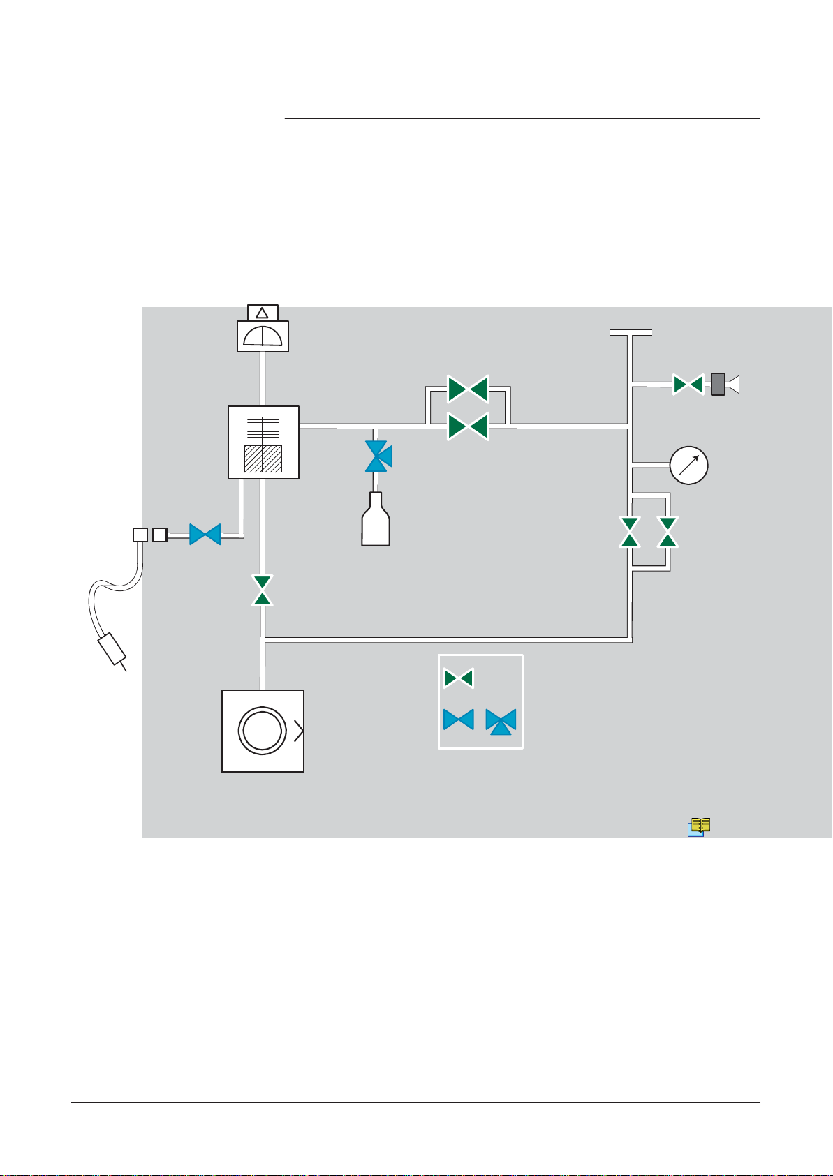
ASM 142 detector operating principle
GB 00208
-
Edition 03
- June
08
Vacuum
circuit
1
2
V
T3
18
V
C
V
T2
V
S
8
4
3
VA1 7
R1 VR2
V
5
15
VT1
Bacosol
Minisol valves
valve
Reference correspondence between valve/vacuum block marks
1 Preamplifier
2 Analyzer cell
3
Detector
inlet port
4 Internal calibrated leak
5 Inlet
pressure
gauge
7 Vent connector
Long
8
15
18
distance sniffer connector
Roughing
primary pump
Detection molecular
(RVP
20 0)
pump (AMP
007I)
A1 Inlet vent valve (6 points)
V
R1
V
R2
V
T1
V
T2
V
T3
V
V
S
Sniffing valve (9 points)
V
C
Calibration valve (7 points)
Roughing
Roughing
Exhaust
Detection
Detection
valve ( point)
valve (2 points)
valve (3 points)
valve (4 points)
valve (5 points)
E
530
/4
Page 12

A
200
ASM 142 detector operating principle
GB 00208
-
Edition 03
- June
08
(Patm
Stand-by mode
Roughing
mode
to 10 mbar inlet
18
1
2
3
VA1 7
V
T1
15
3
pressure)
2/4
15
5
V
R1
VR2
Page 13

A
200
ASM 142 detector operating principle
GB 00208
-
Edition 03
- June
08
Gross
leak
test
(10 mbar to
5x10
inlet
-1
pressure)
mode
mbar
1
2
18
3
VR1
VR2
5
VT1
15
V
3
T3
1
2
Normal
(lower than
5x10
test
-1
mode
mbar
18
VT1
VT2
5
inlet
pressure)
15
3/4
Page 14

A
200
ASM 142 detector operating principle
GB 00208
-
Edition 03
- June
08
Sniffing
test
mode
1
3
2
VA1
7
18
8 V
S
4/4
VT1
15
Page 15

A
201
ASM 142 D detector operating principle
GB 01476
-
Edition 03
- June
08
2
Analyzer cell
V
Roughing
valve (1 point)
3
Detector
inlet port
V
Roughing
valve (2 points)
4
Internal calibrated leak
V
Exhaust
valve (3 points)
V
Detection
valve (4 points)
Vent connector
V
Detection
valve (5 points)
8
Long
distance sniffer connector
V
Sniffing valve (9 points)
10
Outlet pump connector
V
Calibration valve (7 points)
15
Roughing
pump (AMD1)
16
Roughing molecular
pump
18
Detection molecular pump (AMP
007I)
Vacuum
circuit
18
8
V
S
1
2
V
T3
V
C
4
V
T2
VT1
3
VA1 7
V
R1
5
VR2
15
10 12
16
Bacosol
valve
Minisol valves
Reference correspondence between valve/vacuum block marks
E
530
Preamplifier
1
Inlet
Purge
(MDP
pressure
filter
5006 HDS)
5
7
12
gauge
V
A1
R1
R2
T1
T2
T3
S
C
Inlet vent valve (6 points)
1/4
Page 16

A
201
ASM 142 D detector operating principle
GB 01476
-
Edition 03
- June
08
Stand-by mode
1
2
18
V
T1
3
VA1 7
(Patm
Roughing
mode
to 10 mbar inlet
16
pressure)
16
15
15
3
5
V
R1
VR2
2/4
Page 17

A
201
ASM 142 D detector operating principle
GB 01476
-
Edition 03
- June
08
18
1
2
V
T1
VR1 VR2
3
5
Gross
leak
test
mode
(10 mbar to
5x10
-1
mbar
inlet pressure)
16
1
2
V
T2
15
3
18
test
Normal
mode
(lower than
-1
5x10
inlet
mbar
pressure)
16
V
T1
T3
V
15
5
3/4
Page 18

A
201
ASM 142 D detector operating principle
GB 01476
-
Edition 03
- June
08
Sniffing
4/4
test
mode
1
2
18
V
S
8
V
T1
16
15
3
VA1 7
Page 19

A
202
principle
GB 03710
-
Edition 01
- June
08
2
Analyzer cell
V
Roughing
valve (1 point)
Detector
inlet port
Roughing
valve (2 points)
4
Internal calibrated leak
V
Exhaust
valve (3 points)
5
Inlet
pressure
gauge
V
Detection
valve (4 points)
Sniffing valve (9 points)
10
Outlet pump connector
V
Calibration valve (7 points)
12
Purge
filter
15
Roughing
primary pump
(ACP 15)
Detection molecular pump (AMP
007I)
ASM 142 Graph D+ detector operating
Vacuum
circuit
18
8
10 12
V
S
1
2
V
T3
V
C
4
V
T2
VT1
15
16
Reference correspondence between valve/vacuum block marks
3
VA1 7
R1
V
5
VR2
Bacosol
valve
Minisol valves
E
530
Preamplifier
1
3
Vent connector
7
Long
8
16
18
distance sniffer connector
Roughing molecular
(MDP
5006 HDS)
pump
V
A1
R1
V
R2
T1
T2
V
T3
V
S
C
Inlet vent valve (6 points)
Detection
valve (5 points)
1/4
Page 20

A
202
principle
GB 03710
-
Edition 01
- June
08
ASM 142 Graph D+ detector operating
Stand-by mode
1
2
18
V
T1
Roughing
(Inlet pressure:
mode
Patm
16
15
to 10 mbar)
16
2/4
15
3
VA1 7
3
5
V
R1
VR2
Page 21

A
202
principle
GB 03710
-
Edition 01
- June
08
5
ASM 142 Graph D+ detector operating
18
16
18
16
1
1
2
V
T1
2
V
T1
3
VR1 VR2
15
3
V
T2
V
T3
15
5
3/4
Gross
leak
(Inlet
test
pressure:
10 mbar to
5x10
-1
mode
mbar)
Normal
(Inlet pressure:
than 5x10
test mode
lower
-1
mbar)
Page 22

A
202
principle
GB 03710
-
Edition 01
- June
08
ASM 142 Graph D+ detector operating
Sniffing
4/4
test
mode
1
2
18
V
S
8
V
T1
16
15
3
VA1 7
Page 23

A
300
Analyzer cell
operating principle
GB
00007
-
Edition 03
-
September
04
Description
The
analyzer
cell works on the principle of mass spectrometry and is
set to the mass of helium (m/e =
4).
m/e
= atomic mass of the
ionization
particle/number
of electrons lost
on
The principle of magnetic deflexion spectrometry is as follows. The
neutral molecules of the gas being
chamber
beam
(or source of ions) where they are
generated
by
a heated
molecules are transformed into
analyzed
tungsten filament. A
ions.
pass into an
bombarded
large
ionization
by an
electron
number of the
�
He
He
�
�
He
������
���
6
Leak Signal
��������������� ���
�
�
������������������
����������������������
��
���������
��
�����������������
��
������������������
�������������������
�������������������
��������������
������������
�����������
He
������������
Analyzer cell
-
functional
diagram
1/3
Page 24

A
300
Analyzer cell
operating principle
GB
00007
-
Edition 03
-
September
04
Description (continued)
These ionized particles are
accelerated
by an electrical
field.
The entire
property of deflecting the trajectories of the ions along different
according
to their
different masses, is divided into several
only ions with the same
separated
ions (N2+ or
analyzer
to the masses of those ions (to be more
m/e
ratios). Thus the ions
cell is subject to a magnetic field which has
precised, according
beam,
m/e
ratio. The helium ions (m/e = 4)
which
beams,
contained
each
from the lighter (H2+ or H1+, smaller beams) or
O2+,
small
beams).
ions with
containing
heavier
the
curves
are
Because there is a constant magnetic field
accelerator
= 4) follow
electrical field is adjusted so that the helium ions
a pre-determined
trajectory (passing through
and arrive on the target at the input to
(permanent
a
direct current
magnet),
(m/e
diaphragms)
amplifier.
the
The current of helium ions is
helium in the installation and by measuring it we can find the flow
rate of the leak that has been
proportional
detected.
to the partial pressure of
It
is essential that the total pressure in the
-4
10
mbar, so that the trajectories of the electrons and the ions are
disturbed by residual
Around
-3
10
mbar there is a risk of
molecules.
analyzer
damaging
cell is less
the
heated filament.
than
not
In order to
«stray ions», an electrode located in front of the target
the
secondary
«braking electrode».
separate
ions with low
the helium ions from «noise» caused by
eliminates
energies.
This electrode is called
the
There is an auxiliary electrode at the top of the cell,
a
plate, which collects the ions that are heavier than helium. This
electrode thus
measures
electrode serves as the plate for
«triode
2/3
electrode».
the total pressure in the
a
triode
gauge,
shaped like
analyzer.
This
hence its name of
Page 25

A
300
Analyzer cell
operating principle
GB
00007
-
Edition 03
-
September
04
Design
manufacture
and
Great care has been taken with the design and manufacture of
the cell in order to
and to achieve excellent stability:
– the metal parts are made of stainless
– the filament holder is made of
– there is an integral
repeatedly
amplifier.
obtain the same
steel,
machined aluminium,
characteristics
The cell assembly is
a
vacuum
–
– an optic holder
a permanent magnet,
–
amplifier.
– an
chamber
composed of:
or deflection
flange,
chamber,
•
The vacuum
The analysis cell vacuum
hollow with
(that are installed on the «optics holder» flange) are
chamber:
a rectangular opening
chamber
is made of light alloy.
into which the
electrodes,
placed.
It
is
•
The optics holder
The optics holder flange supports all the electrodes and
connections in the cell. They
– the sealed power supply socket, mounted on
– the amplifier, mounted on an elastomer
vthe supporting block which screens the target and on which
source of ions is
– the source of ions, which is made up of 2
• a
filament
•
an ionization
and a mass ion emitter.
holder,
flange:
mounted,
chamber
include:
with a stainless steel electron
gasket,
par
a
ts:
metal
electrical
gasket,
the
collector
The filament holder
with respect to the ionization
mechanically
chamber.
positions the tungsten filament
The electron collector and the filament have been
and positioned so that the
stabilizes at
filament. The cell is thus
the pieces being tested without the need of any special
system.
400°C
under
temperature
bombardment
rendered
of the electron
and
immune to
designed
collector
radiation
contamination
from
heating
the
from
3/3
Page 26

A
400
T
esting methods
GB
00008
-
Edition 05
-
February
02
Over
view
Leak detection is used to detect
micro-openings,
parts. The detection of these cracks involves the use of
gas, which is
capable
of infiltrating the smallest leak quickly: Helium.
porosities, etc. in test
a
light
tracer
The detector samples and measures the helium flow rate entering
test part via the
leak(s).
the
The testing method is selected
measurement accuracy required:
no
The part can be
connected to
The part is
sealed
an evacuation line
yes
Its
characteristics
allow it to
evacuated
be
yes
10
-1
mbar.
SPRAY
laeak rate
to
locating the
method
measurement
l/s
and possibility of
leak.
from
10
-10
no
Minimum
mbar.l/s
the
Its
characteristics
allow it to
pressurized
or
a
mixture
helium
SNIFFING
detectable
and possibility of
leak.
with helium
containing
yes
method
leak of
be
locating
according
-6
10
to the test part and
Its
characteristics
allow it to be
in
a vacuum
vessel
BOMBING
The sensitivity is limited by
internal dead
well as on the bombing time and
pressurization value.
Global test without possible
of the
leak.
volume of the part
the
placed
yes
method
the
location
as
the
1/4
Page 27

A
400
T
esting methods
GB
00008
-
Edition 05
-
February
02
Helium
and signal
(inboard testing)
2/4
concentration
displayed
Spray
method
Response time
In
leak
accordance
detection,
to the He
the signal
concentration
displayed
will
rate in the gas used for
change.
Example: signal
100
(with
% He in the gas
Signal
displayed
on the leak
This involves removing air from the test part,
analyzer
detector
and then
He
The part is
% He)
used
Global
part
placed
displayed
connected
1x10
spraying
test
under
with
a 1x10
to the detector inlet.
100 % 10 % 1 %
-7
mbar
.l/s
helium over the outer sur
detector
a
cover, into which helium is
injected.
The leak cannot be
located.
The detector measures the flow of helium
When
on the
there is
spraying
analyzer:
a response
starts, the leak signal is not
time which
depends
and the helium pumping speed S of the system at the
part,
according
T
= V/S
T
is the time required for the signal to reach 63 % of the final
to the following
(T
in
seconds,
relation:
V in litres, S in
-7
mbar.l/s calibrated leak
1x10
-8
mbar
.l/s
connecting
Spray
or
probe
spray
He
Potential leaking
sprayed
The leak can be
on the volume V being
with
penetrating
displayed instantaneously
l/s)
face.
test
part
helium.
located.
the
opening
the
-9
1x10
mbar
it to
the
detector
areas are
part.
tested
of
value.
.l/s
the
Page 28

A
400
T
esting methods
GB
00008
-
Edition 05
-
February
02
Sniffer
(outboard testing)
method
The test part is
Distance Sniffer)
pressurized
probe,
samples the helium
with helium. The detector, via an
escaping
from the
LDS
part.
(Long
Global test
or
He
The part is
part
LDS
placed
detector
under
a
cover containing a sniffer
probe.
The leak cannot be
The helium from the
accumulates over time inside
cover. The detector
the
concentration
located.
leak
measures
of
helium.
the
Local sniffing
He
part
LDS
test
detector
The sniffer probe is moved
areas
The leak can be
The signal supplied by
analyzer
measurement
The sniffer probe only
part of the helium
from the part. The
depends
separating
of the
likely to contain
located.
is not
a direct
of the
leak.
escaping
sample
on the
distance
the leak from the tip
probe.
leaks.
the
samples
over
3/4
Page 29

A
400
T
esting methods
GB
00008
-
Edition 05
-
February
02
Bombing method
This method is used for sealed objects that cannot be
directly to the detector
(semiconductors, waterproof watches, etc.).
connected
He
The part is
placed
part
Chamber 1
in
a chamber
part
Chamber
containing
2
pressurized helium.
He
detector
The helium
The part is then removed from the
vacuum
escapes
penetrates
the part if it has
a leak.
chamber
chamber
which is
connected
to the detector. The helium
from the part through the leak and
and
placed
in
another
produces a signal.
This signal is not a direct
pressure inside the part is difficult to
important part such as: the
pressure, the internal volume, the
4/4
measurement
determine.
pressurization
aeration
of the leak as the helium
Several parts play
time, the helium
bombing
time, the size of the
leak.
an
Page 30

A
401
About Helium and hydrogen
GB 02760
-
Edition 02
- June
08
Helium
Helium is the
representing
other
elements represent
second most common element
about 23 % of the total matter. 76 % is Hydrogen.
an insignificantly small fraction of the total.
in the universe,
All
Helium was
18, 1868.
element
common
very
is actually not abundant.
during the formation of earth escaped to space. Helium is created,
deep in the earth from the radioactive decay of Uranium and Thorium
which also
discovered
volcanic
spectrum
the
discovered
The
discovery in the
its name: “helios” in Greek
in the
generates
in 1881 by
gases emanated
as already known from the sun.
by
spectroscopy
sun’s chronosphere
universe most
Since
the earth its internal heat. On earth Helium was
spectroscopy
by the mountain showed the
of it is in the
it is so light all the Helium present
in a solar eclipse on August
gave the new
means
“sun”. While Helium is
stars:
of Mount
Vesuvio
on earth it
in Italy – the
same
lines in
Helium
of Krypton and 60
are isolated from air by liquefaction and rectification
as a contrary is “extracted” from natural gas and oil wells. Helium
comes
annual world wide production is ca. 3x10
4,500 tons.
concentration
up with the natural gas and is separated and stored. The
in the
times
atmosphere
higher than
is 5
times
Xenon. The
7 m3
bigger than the one
heavier noble gases
process.
or
Helium
Helium is
is so light that
other hand there is a
to earth.
world wide
constantly
This
gives a dynamic equilibrium and is the reason for the
constant concentration
seeping up from the ground all around us, but it
almost
all of it
constant
escapes
flow of Helium from space and the sun
into space fairly rapidly. On the
of ca. 5 ppm Helium in
air.
Helium is a very light
gases;
it is the
most
colorless element
difficult gas to liquefy.
and it is one of the six noble
Helium is a noble gas, which
all practical
protect things from oxidation – and of
gas.
intents
and
means
purposes. It’s used
it doesn’t react with anything for
course
as an inert shield gas to
as leak detection tracer
Helium is a 100 % green gas and has
impact on the atmosphere.
absolutely
no environmental
1/2
Page 31

A
401
About Helium and hydrogen
GB 02760
-
Edition 02
- June
08
Helium and
detection:
which purity ?
leak
Helium is available in many different purity
purity is
requested
from
some
laboratories for
very accurate analyses.
The use
doesn’t require
is enough
of the Helium as a tracer gas into a
such
attention. A purity in the range of 97 % to 99 %
.
levels,
the
fundamental
mass
spectrometer
highest
activities or
level of
There
is
absolutely
Hydrogen
cell analyzer by using standard purity level of Helium gas.
Hydrogen (H2) is the
of 0.0695 and a boiling point of -423 °F (-252.8 °C) at atmospheric
pressure.
It is a
concentrations
several methods,
of ammonia, and recovery from
manufacturing
transported
as a gas or a cryogenic
Hydrogen is flammable in the
air or oxygen and can detonate in the range 18 % to 60 % in air or
.
ygen
ox
2/2
no risk of accuracy lost or contamination for the
lightest element,
colorless, odorless, tasteless,
has a
gaseous
specific gravity
flammable gas found at
of about 0.0001 % in air. Hydrogen is produced by
including
and
petroleum
steam/methane
by-product streams
reforming, dissociation
from chemical
reforming. Hydrogen can be stored and
liquid.
concentration
range 4 % to 75 % in
Page 32

A
500
Operator
interface: control
panel
GB
00209
-
Edition 02
-
September
04
15
mbar.l/
s
Pa.m3/s
Torr.l/
14
-8
10
2
10
s
-7
-6
-5
-4
-3
-2
10
10
10
10
3
10
mba
hPa
Torr
ZERO
5
7
8
r
STDBY
EVAC
6
10
10
12
9
CYCLE
13
10
TEST
F1
F3
NEXT
-
+
SET POINTS SPECTRO MAINTENANCE OTHER
RESET
F2
F4
LEAK RATE
-12
-11
10
10
-10
10
10
-3
-2
-1
10
10
INLET
PRESSURE
AUTO CAL SNIFFER ZERO
Operation
COR
-9
-8
10
10
1
2
1 10
10
part
mbar.l/
s
Pa.m3/s
Torr.l /s
-7
-6
-5
-4
-3
10
10
10
10
3
10
mba
r
hP
a
STDBY
Torr
10
EVAC
CYCLE
-2
10
TEST
16
-11
10
-2
10
10
PRESSURE
10
-1
COR
-10
1 10
SNIFFER
-9
10
1
2
RESET
F2
F4
11
1
LEAK RATE
-12
10
-3
10
INLET
29
AUTO CAL
3 4
F1
18
F3
20 21 22
NEXT
19
24
SET POINTS SPECTRO
25 26 27
17
-
+
23
MAINTENANCE OTHER
28
1 Inlet port pressure
2 Control and menu selection indicators (ON when
3 Auto-calibration
4 Sniffing mode
5 Auto-zero
6 Cycle
ON/OFF
START/STOP
analog display
STAR
T/ABORT control key
ON/OFF
control key
control key
control key
activated)
Setting and
maintenance
part
(*)
*
Operator
access to setting and
maintenance
part
depends
on the user interface level.
User interface level C
120
7 Control keys (4 keys)
8 Standby
9 Evacuation
T
10
est
11 Helium signal
12 Helium signal
ON/OFF indicator
ON/OFF indicator
ON/OFF
indicatort
analogic display
analogic
13 Helium signal Zero scale
14 Correction factor COR indicator (applied to digital
15 Units
ON/OFF indicator
16 Helium signal digital
17 Alphanumeric display (4 lines x 20
18
Parameter function keys (1 key per display line)
19 Modification access keys (4 keys)
20
21/22
23
NEXT
: next
display/parameter
Plus or minus value adjustment,
RESET
of previously
displayed
scale
ON/OFF indicator
ON/OFF indicator
display
circular function
parameter
values (cancels temporary inputs)
characters)
selection, audio volume adjustment keys
display)
Parameter
function keys (1 key per display line)
F1
F3
F2
F4
NEXT
- +
SET POINTS
SPECTRO MAINTENANCE OTHER
RESET
LEAK RATE
-12
10
-3
10
INLET PRESSUR E
10
-2
10
AUTO CAL
-11
Helium signal
mbar.l/
-8
s
3
Pa.m
/s
Torr.l /s
-7
-6
10
10
3
10
mba
r
hPa
Torr
ZERO
COR
-10
-9
10
10
10
1
-1
10
2
1 10
10
SNIFFER
-5
10
STDBY
EVAC
display
-4
10
10
CYCLE
-3
-2
10
TEST
24 Menu selection access keys (4 keys)
25
26
SET
POINT menu selection key
SPECTRO
calibration
and
analyzer
cell configuration menu selection key
27 MAINTENANCE menu selection key
29 Remote control
28
OTHER
menus selection key (test mode selection, inlet
connection
VENT
selection,
date/time)
Modification access keys (4 keys) Control keys (4 keys)
Menu selection
access
keys (4 keys)
Remote control interface C
Control panel with graphic interface (option) C
control and menu selection
(ON when
400
440
and
indicators
activated)
1/2
Page 33

A
500
Operator
interface: control
panel
GB
00209
-
Edition 02
-
September
04
15
mbar.l/
s
Pa.m3/s
Torr.l/
14
-8
10
2
10
s
-7
-6
-5
-4
-3
-2
10
10
10
10
3
10
mba
hPa
Torr
ZERO
5
7
8
r
STDBY
EVAC
6
10
10
12
9
CYCLE
13
10
TEST
F1
F3
NEXT
-
+
SET POINTS SPECTRO MAINTENANCE OTHER
RESET
F2
F4
LEAK RATE
-12
-11
10
10
-10
10
10
-3
-2
-1
10
10
INLET
PRESSURE
AUTO CAL SNIFFER ZERO
Operation
COR
-9
-8
10
10
1
2
1 10
10
part
mbar.l/
s
Pa.m3/s
Torr.l /s
-7
-6
-5
-4
-3
10
10
10
10
3
10
mba
r
hP
a
STDBY
Torr
10
EVAC
CYCLE
-2
10
TEST
16
-11
10
-2
10
10
PRESSURE
10
-1
COR
-10
1 10
SNIFFER
-9
10
1
2
RESET
F2
F4
29
11
1
LEAK RATE
-12
10
-3
10
INLET
AUTO CAL
3 4
F1
18
F3
20 21 22
NEXT
19
24
SET POINTS SPECTRO
25 26 27
17
-
+
23
MAINTENANCE OTHER
28
1 Inlet port pressure
2 Control and menu selection indicators (ON when
3 Auto-calibration
4 Sniffing mode
5 Auto-zero
6 Cycle
ON/OFF
START/STOP
analog display
STAR
T/ABORT control key
ON/OFF
control key
control key
control key
activated)
Setting and
maintenance
part
(*)
*
Operator
access to setting and
maintenance
part
depends
on the user interface level.
User interface level C
120
7 Control keys (4 keys)
8 Standby
9 Evacuation
T
10
est
11 Helium signal
12 Helium signal
ON/OFF indicator
ON/OFF indicator
ON/OFF
indicatort
analogic display
analogic
13 Helium signal Zero scale
14 Correction factor COR indicator (applied to digital
15 Units
ON/OFF indicator
16 Helium signal digital
17 Alphanumeric display (4 lines x 20
18
Parameter function keys (1 key per display line)
19 Modification access keys (4 keys)
20
21/22
23
NEXT
: next
display/parameter
Plus or minus value adjustment,
RESET
of previously
displayed
scale
ON/OFF indicator
ON/OFF indicator
display
circular function
parameter
values (cancels temporary inputs)
characters)
selection, audio volume adjustment keys
display)
Parameter
function keys (1 key per display line)
F1
F3
F2
F4
NEXT
- +
SET POINTS
SPECTRO MAINTENANCE OTHER
RESET
LEAK RATE
-12
10
-3
10
INLET PRESSUR E
10
-2
10
AUTO CAL
-11
Helium signal
COR
-10
-9
10
10
-1
1 10
10
SNIFFER
mbar.l/
s
3
/s
Pa.m
Torr.l /s
-8
-7
10
1
10
-6
10
10
2
3
10
mba
r
hPa
Torr
ZERO
-5
10
STDBY
EVAC
display
-4
10
10
CYCLE
-3
-2
10
TEST
24 Menu selection access keys (4 keys)
25
26
SET
POINT menu selection key
SPECTRO
calibration
and
analyzer
cell configuration menu selection key
27 MAINTENANCE menu selection key
29 Remote control
28
OTHER
menus selection key (test mode selection, inlet
connection
VENT
selection,
date/time)
Modification access keys (4 keys) Control keys (4 keys)
Menu selection
access
keys (4 keys)
Remote control interface C
Control panel with graphic interface (option) C
control and menu selection
(ON when
400
440
and
indicators
activated)
2/2
Page 34

A
600
Options
ASM
182
T
ASM
192 T2
ASM
192 TD+
ASI
22
A
700
GB 02446 -
Edition
04 -
June
08
Metal seals
Inlet
Units
Languages
3 masses
Automatic
Roughing
Interface
Remote
Test
Stainless steel
Control panel with graphic
Control panel racks
Sniffing*
Cables lengths
T
Voltage configuration
Power
Standard
*also available in accessories
Which options
which model?
port
test
chambers
system
board*
control cable length
of gas line
cover (UCT)
ransport
cart*
plug
remote
control*
for
inter
face*
S
102
122 D
ASM
ASM
1
2
3
4
5
6
7
8
9
10
11
12
13
14
15
A
700
-
-
• •
•
• • • • • • • • • • • • •
• • • • • • • • • • • • •
• • •
•
• • • • • • • • • • • • •
• • • • • • • • • • • • •
•
S
142
142
ASM
•
• • • •
•
142 D
ASM
ASM
• • • • • • • • •
• • • • • • • • •
• • •
T
Graph D+
ASM
192
ASM
• • • • • • •
• •
• •
182 TD+
ASM
•
•
•
•
• •
• • •
T2D+
192
1002
ASM
ASM
•
•
•
•
1/5
Page 35

A
600
Options
GB 02446 -
Edition
04 -
June
08
Inlet
port
Units
Metal seals
Inlet and high
with metal
1
detector
usefull
in case of high
contaminated
ASM 122 D:
DN 40 inlet port for convenience.
2
ASM 1002:
vacuum
seals
instead of
against contamination with helium.
sensitivity
environment”.
The
standard DN 25 inlet port can be replaced by a
The test
chamber can be replaced by a DN 25 inlet
port for convenience.
3
The user
T
orr
can choice the unit of the software: mbar.l/s, Pa.m3/s or
.l/s.
manifolds and the analyzer cell are equipped
elastomer seals
to protect the leak
This
option is particularly
helium leak detection in an ”helium
Localisation
of the metal seals
F
800
Languages
3
masses
The user
German or Japanese.
4
Note: ASM 142 S: English/French/German/Spanish.
can choice the language of the software:
ASM 1002: English/French.
For
use
of one of the 3 following tracer gases:
2.
Helium 4, Helium 3 or Hydrogen
5
English,
French,
Automatic test
chambers
2/5
This
is
used
for the automatic bombing
When the chamber cover is closed, the
contact.
6
aluminium
3
• a hemispheric
•
a cylindrical chamber,
maximum
•
a cylindrical chamber,
maximum
alloy
models
are available:
chamber, Ø 72 mm, depth 31 mm
maximum
depth 68 mm
(medium
maximum
depth 200 mm (large model).
Note: ASM 142: large model not available.
testing
test
cycle is initiated, via
Ø 85 mm and
model),
Ø 160 mm and
of small components.
a
(small
model),
Page 36

A
600
Options
GB 02446 -
Edition
04 -
June
08
Roughing
Remote
system
Interface
control cable
7
board
8
In order to reduce the roughing time when
second
•
•
Apart from the roughing capacity, the weight and the power
consumption,
remain the same.
The
which will offer a
•
•
auto-cal
•
•
maintenance
This RS
from a
monitor the
3
roughing pump can be added to the roughing system:
ASM 192 T /
ASM 192 TD+ / 192 T2D+ total capacity: 50
helium leak
3 operating modes: basic, advanced, printer;
possibility to
etc...);
possibility to obtain and adjust the settings;
possibility to obtain all the
232 is the
PC
lengths
are proposed: 5 m (16
192 T2
the
characteristics
detector
remote
purposes.
(data recording on an
detector
total capacity: 40
can be equipped with a software version
complete RS
control the
most effective
from a small PLC.
232 protocol:
maintenance
and the
detector
interface to
Excel sheet,
Ft),
testing
m3/h
use
(start/stop, autozero,
information for preventive
10 m (32
large
or 24 cfm.
m3/h
of the leak detector
supervise
for
instance)
Ft)
and 15 m (49 Ft).
volumes,
or 36 cfm.
your leak test
a
and/or to
length
Test
of gas
9
line
10
Used to perform spray
with a reduced
carrier gas injected in
In this case, the
connector
specific to this option.
testing
response
viscous
detector
on long lines (typical diameter 1/4’
time due to the
flow.
is equipped with an additionnal
transfer
of the helium by
1/4”
’),
a
VCR
Stainless steel
cover
(UCT)
11
Designed for
T
echnology”).
The
front and rear
use
of the unit in clean rooms (“Ultra Clean
covers
and frame are made of
stainless
steal.
3/5
Page 37

A
600
Options
F1
F2
F3
F4
GB 02446 -
Edition
04 -
June
08
The
Control panel
with
graphic
inter
face
control panel with graphic interface is equipped with a color
screen.
touch
control panel
It allows it to have, as a
functions,
a graphic interface.
supplement
to the standard
12
mbar.l/s
Pa.m3/s
LEAK RATE
-12
10
COR
-11
-10
-9
10
10
10
Torr.l/s
-8
-7
-6
-5
-4
-3
10
10
10
10
-2
10
10
10
SET
POIN TS SPECTRO MAINTENANCE OTHER
AUTO CAL SNIFFER ZERO
STDBY
EVAC TEST
CYCLE
Control panel
racks
13
The
leak
detector
is delivered with 5 m (16
Ft)
or 10 m (32
Ft)
cables.
Standard
The
setting,
standard control panel rack allows to manage the detector:
test,
calibration,
...
LEAK RATE
-12
10
COR
-11
-10
10
10
mbar
.l/s
Pa.m3/s
T
orr
.l/s
-9
10
-8
-7
-6
-5
-4
-3
10
10
10
10
-2
10
10
10
1
2
1 10
3
10
10
ZERO
mbar
hPa
T
orr
STDBY EVAC TEST
CYCLE
-3
-2
-1
10
10
10
INLET
NEXT
-
+
RESET
SET
POIN TS SPECTRO MAINTENANCE OTHER
PRESSURE
AUTO CAL
SNIFFER
T
ouchscreen
The
control panel with graphic interface is equipped with a color
touch
control panel
screen.
It allows it to have, as a
functions,
a graphic interface.
supplement
to the standard
LEAK RATE
-12
10
COR
-11
-10
10
10
mbar.l/s
Pa.m3/s
Torr.l/s
-9
-8
-7
-6
-5
-4
-3
10
10
10
10
10
STDBY
EVAC TEST
-2
10
10
10
SET
POIN TS SPECTRO MAINTENANCE OTHER
4/5
AUTO CAL SNIFFER ZERO
CYCLE
Page 38

A
600
Options
GB 02446 -
Edition
04 -
June
08
Snif
fing
This
14
option allows to work in sniffing mode.
The
ASI 22 can be fitted with a long distance sniffer probe kit
composed
n
a sniffing probe (to order separately A
n
a sniffing cell,
n
2 male and female connectors,
n
the connecting
(Installation
of the following:
accessories
B
250)
700)
and the hose.
Câbles lengths
2 cables
module are proposed: 2 m (6 ft) ou 5 m (16 ft).
15
lengths
connecting the
electronic
module and the detection
5/5
Page 39

A
700
Accessories
ASM
192 T2
ASM
192 TD+
ASM
1002
Headphone
connector
(required interface
board)
Foot pedal for cycle command
(1.5 m/ 5 feet)
A
600
Covered sniffer probe and
remote
control
kit
GB 02447 -
Edition
04 -
June
08
Which
accessories
which model?
Standard remote
Long distance
10 m/30 feet
T
ransport
Calibrated helium leaks
Calibration accessory
Spray probe
Interface
Inlet adaptor
Printer
Inlet filter
Short
*also available in options
distance sniffer probe
Bombing chamber
Test
chambers
Neutral gas vent line kit
4 swiveling
Bottle
handle for cart
Fitted
mini-printer
sniffer
LDS
cart*
board* (p/n 107657)
wheels
for
control and cable*
(LDS)
probe
extension
kit
1
2
3
4
5
6
7
8
9
10
11
12
13
14
15
16
17
18
19
20
S
102
122 D
ASM
ASM
• • • • • • • • • • • • •
• • • • • • • • • • • • • •
• • • • • • • • • • • • • •
• • •
• • • • • • • • • • • • • •
• • • • • • • • • • • • • •
• •
• •
• •
• •
S
142
142
ASM
•
•
• • •
• • • •
•
142 D
ASM
ASM
•
•
• • • • • • • • • •
• • • • • • • • •
• • • •
• • • • • • • • •
• • • • • • • • •
•
Graph D+
ASM
•
T
T
182
192
ASM
ASM
•
•
•
•
•
•
• •
•
•
•
• •
•
182 TD+
ASM
•
•
•
•
• •
192 T2D+
ASM
•
•
•
•
•
•
•
1/14
22
ASI
Page 40

A
700
Accessories
ASM
192 T2
ASM
192 TD+
ASM
1002
Control panel rack *
cable: p/n
112776
A
600
GB 02447 -
Edition
04 -
June
08
Which
2005 IS pump
Pressure measurement
Ventilation kit
Control panel with graphic
(p/n:
n
Standard - 5 m (15 feet)
cable: p/n
n
Standard - 10 m (32 feet)
cable: p/n
n
Touchscreen - 5 m (15 feet)
cable: p/n
n
Touchscreen - 10 m (32 feet)
Long distance
Bootle
Remote control holder
*Also available in option
2/14
accessories
which model?
11171
6)
113134
112775
113133
sniffer kit * (p/n: 104757)
handfe for cart
for
21
kit
inter
face*
22
23
A
A
24
25
600
600
S
102
122 D
ASM
ASM
•
142
ASM
S
142
142 D
Graph D+
ASM
ASM
ASM
•
•
•
•
T
T
182
192
ASM
ASM
•
182 TD+
ASM
•
192 T2D+
ASM
22
ASI
•
•
•
•
•
Page 41

A
700
Accessories
Designation
Part No
Cable of 35 m/1
377˝
802
768
Cable of 40 m/1
575˝
802
769
GB 02447 -
Edition
04 -
June
08
Remote
control
1
The remote
to place it on a magnetized
signal and has
control is equipped with a magnet allowing the operator
surface. The
access
to control
autocalibration and auto-zero.
models
2
are available:
•
1 standard for all leak
detectors
operator can read the helium
keys such
as cycle command
except ASM 102 S /
ASM 142 S:
Remote
Designation Part No
Unit: mbar.l/s - Front
Unit: Torr
Unit: Pa.m3/s - Front
Unit: Pa.m3/s - Front
Note:
series
control with 5 m/15 feet cable length:
face in English
.l/s -
Front
face in English
face in English
face in Japanese
The remote
control is delivered in standard with the ASM
and ASM 122 D.
English
serigraphy
Japanese
106
688
108
881
108
880
106
690
192
serigraphy
mbar
.l/s
or
T
orr
.l/s
or
•
1 specific for sniffing leak
Remote
Designation Part No
Unit: mbar.l/s
control with 5 m/15 feet cable length:
Cable for
Cable of 10
Cable of 15
Cable of 20
Cable of 25
Cable of 30 m/1181˝
mbar
-
Front
remote
m/394˝
m/591˝
m/787˝
m/984˝
Pa.m3/s
-1
10
.l/s
face in English 112
control
detectors
(remote
(ASM 102 S /
control not provided):
ASM 142 S):
Pa.m3/s
only
-1
10
Pa.m3/s
110
110
802
802
802
747
881
882
494
339
767
Only Cable
Cable of 45 m/1771˝
Cable of 50 m/1
969˝
802
770
802
771
3/14
Page 42

A
700
Accessories
Designation
Part No
Tube
length 20
m/787˝
802
826
Tube
length 30 m/1181˝
802
827
802
828
Tube
length 50 m/1
969˝
Tube
length 60 m/2362˝
802
830
Tube
length 70 m/2
756˝
802
831
802
832
Tube
length 90
m/3543˝
Tube
length 100
m/3937˝
802
834
Tube
length 30 m/1181˝
802
836
Tube
length 40 m/1
575˝
802
837
802
838
Tube
length 60 m/2362˝
802
839
Tube
length 70 m/2
756˝
802
840
Tube
length 80
m/3150˝
802
841
Tube
length 100
m/3937˝
802
843
GB 02447 -
Edition
04 -
June
08
5 m/15
Ft
canalisation
10 m/32
Ft
canalisation
Rigid nipple
Flexible
nipple
Rigid nipple
Flexible
nipple
9 cm
30 cm
15 cm
45 cm
9 cm
30 cm
15 cm
45 cm
LDS
probe part number
Long Distance
Snif
Sniffer probe with a rigid nipple Sniffer probe with a flexible nipple
fer
probe
2
SNC1E1T1 SNC1E2T1 SNC1E3T1 SNC1E4T1 SNC2E1T1 SNC2E2T1 SNC2E3T1 SNC2E4T1
T
ube
Long
distance sniffer with
Tube
length 40 m/1
575˝
short
regid nozzle:
802
829
Nozzle length = 9
cm/3.5”
Tube
length 80
m/3150˝
802
833
T
ube
Nozzle length = 45
4/14
cm/18”
Long
distance sniffer with long flexible nozzle:
Designation Part No
Tube
length 20
Tube
length 50 m/1
Tube
length 90
m/787˝
969˝
m/3543˝
802
835
802
842
Page 43

A
700
Accessories
GB 02447 -
Edition
04 -
June
08
10 m/30 feet
extension
Headphone connector
LDS
3
4
Used to extend the
Part
No:
090216
With the headphone connector, the operator can
LDS
probe by 10 m/30 feet.
headphone to its detector.
Part
No:
A459818
The
headphone
detector
must be equipped with the interface board option.
connector
is an
accessory
connect
but to
a
use
it, the
T
ransport cart
ASM 182 range
Part
5
No:
111196
Which headphone
used?
C
410
5/14
Page 44

A
700
Accessories
610 mm/24.02 inch
335
mm
/
8
inch
1040
mm/
GB 02447 -
Edition
04 -
June
08
T
ransport
cart
(ctd)
ASM 142 range
It can be fixed to the detector.
Part
No:
108068
40.95 inch
13.1
ASM 142 range
In addition to the standard cart
(p/n 108068), a 4
steel
cart is proposed for 142 series.
Part
No:
No:
802862
100913
Foot
pedal for
cycle
Part
wheels
stainless
6/14
Part No:
command
(1.5 m/ 5
100913
feet)
6
Page 45

A
700
Accessories
Model
Part No
DN 16
110715
DN 25
110716
GB 02447 -
Edition
04 -
June
08
Calibrated Heli
Helium 3 and
external calibrated
Calibration
Hydrogen
calibrated
Principle
recalibration
accessory
um
leaks
7
leaks
leak
8
There
are
several
leaks, with or without reservoir, with
or without valve, covering
ranges.
The
types of calibrated
several
leak
choice of the appropriate
external calibrated leak depends on the
application requirements.
For further information on the Adixen
calibrated leaks, please refer to our
product catalog or
A.V.T.F. sales
engineer.
consult
your local
Most of the Adixen calibrated leaks are
delivered with a calibration certificate.
The manufacturer
and Hydrogen.
does not supply the calibrated leaks in Helium
All Adixen calibrated leaks are based on permeable membrane
technology.
Most calibrated leaks last many years even though the helium is
permanently
amount of helium contained in the reservoir: yearly
escaping (the leak rate is very small in comparison to the
loss
on the calibrated leak identification label).
However, it is
reservoir)
recalibrated on regular
recommended
to have every calibrated leak (with
intervals
to validate its value: this is
applicable for both internal and external calibrated leak
Recalibration
period of the calibrated leak depends on its leak rate
value.
Recommendation
THE RECALIBRATION INTERVALS SHOULD
Please consult
information.
Used to
leak and the sniffer probe for
a calibration.
connect
for proper Quality Control:
your local Alcatel
Sales representative
the alibrated
NOT
EXCEED
for additionnal
2 YEARS.
3
is indicated
s.
7/14
Page 46
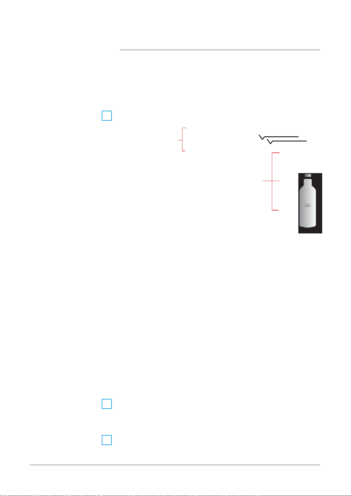
A
700
Accessories
GB 02447 -
Edition
04 -
June
08
Spray probe
Helium spray probe.
Part
9
No:
Spray gun
109951
Long
nozzle
2 needles
Short
nozzle
5 m plastic tube
M 1/4NPT
M
3/8G
M 1/8G
He
bottle
Spraying Helium in order to detect a leak is
usually
very easy,
especially if you need fast and rough detection.
Spraying Helium could also become a technical challenge when you
need to pinpoint very fine leaks, more so, when they are located in
areas with difficult access.
The
Helium spray gun is an easy to
allows you to work in various conditions of test:
•
Multi standard:
the Helium bottle (M
•
Multi purpose:
and 290 mm
•
Standard leak mode: for quick and rough leak tests.
•
Fine
The
the
Printer
Inlet adaptor
8/14
Adaptator plug is
part
10
Part
The manufacturer
connected
11
leak mode.
Helium spray gun is provided with 2 standard
adjustment
(test
chamber) of the detector.
No:
067791
to the leak
- RS232
-
40
serial type
columns
thanks
to the 3 different adapters to be
1/4 NPT, M
thanks
/
14.4 inch.
to the 2 nozzle
of the Helium flow at the outlet of the nozzle.
necessary
to
does not supply the printers.
detector
minimum.
use
and
3/8G
connect
multipurpose
and M 1/8G).
lengths
of 80 mm / 3.14 inch
needles
the calibrated leak to the inlet
The
printer should be
tool which
connected
wich
to
allow
and have the following characteristics:
Page 47

A
700
Accessories
70 μm
stainless steel mesh
filter
16
072
721
70 μm
stainless steel mesh
filter
25
072
857
40
067
636
20 μm inlet filter
20 μm inlet filter
40/40
105
842
20 μm inlet filter
40/25
105
843
25/25
105
844
5 μm inlet filter
40/25
105
846
20 μm inlet filter
Ø 114 mm
105
847
Ø 114 mm
105
848
DN 40 flange and a 1.5
meter
tube (5 ft)
DN 40 flange
DN 25 flange
14 mm
GB 02447 -
Edition
04 -
June
08
Inlet filters
12
Designation DN Flange Part No
Short distance
to the inlet part of a
leak
snif
probe (to
connected
detector):
fer
be
13
70 μm
stainless steel mesh
filter
25/25
105
5 μm inlet filter
5 μm inlet filter
40/40
105
5 μm inlet filter
O’ring, Ø 5 mm
T
emperature
coefficient: 7 % per °Celcius.
Standard leak rate: 2x10
Able to
measure
helium
-4
mbar
.l/s
concentration
Ø 114 mm 082
inside water or liquids.
Designation DN Flange Part No
Sniffer probe with membrane,
Sniffer probe with membrane,
Sniffer probe with membrane,
Sniffer probe with
14 mm O.D.
membrane
smooth
tube connection
and
40
40
25
Ø
067
067
103
067
841
845
152
683
677
592
678
9/14
Page 48

A
700
Accessories
(Ø 150
- L
200 - Vol.: 3.5 l)
(Ø 150
- L
200 - Vol.: 6.4 l)
25
795
716
Adaptator DN 40 to
USA 1 1/8
OD tube
GB 02447 -
Edition
04 -
June
08
Designation
Part No
802
452
802
453
Small
test
chamber DN 50 (3)
802
454
Medium
test
chamber DN 25 (1)
802
455
Medium
test
chamber DN 40 (2))
802
456
Large test
chamber DN 40 for ASM 182 T/TD+
802
458
Large test
chamber DN 40 for ASM 192 T/TD+
802
459
Large test
chamber DN 50 for ASM 192 T2/T2D+
802
460
Bombing
Test
chambers
chamber
14
15
Designation DN Flange Part No
Bombing chamber 10 bars
Bombing chamber 25 bars
Adaptator DN 25 to
•
Small
test
test
chamber, Ø 72 mm, depth 31 mm
•
Medium
test
chamber, Ø 85 mm, depth 68 mm
chamber: hemispherical
test
chamber: cylindrical
USA 1 1/8
OD tube
-
-
40
067
786
786
396
397
890
•
Large test
chamber, Ø 160 mm, depth 100 mm
chamber: cylindrical test
10/14
Small
test
chamber DN 25 (1)
Small
test
chamber DN 40 (2)
Medium
(1) ASM 142
(2) ASM 122 D
(3) ASM 192 T2/T2D+
test
chamber DN 50 (3)
-
ASM 142 D - ASM 122 D
-
ASM 182 T/TD+ - ASM 192 T/TD+
802
457
Page 49

A
700
Accessories
GB 02447 -
Edition
04 -
June
08
Neutral gas
vent
line
kit
16
Part
No:
801421
Neutral gas
vent
line
kit
4 swiveling
wheels
(Ø 125
kit
mm)
17
Soft wheel: improve the mobility
Customers
1, 2, 3 or 4
Part
No:
have the possibility to lock
wheels
801846
independently.
11/14
Page 50

A
700
Accessories
GB 02447 -
Edition
04 -
June
08
Length
Covered
sniffer
and remote control
probe
kit
18
= 5 m/1
Part
No:
802844
97”
Long distance
sniffer probe
Remote
mbar.l/s - English
control:
Bottle
12/14
handle for cart
19
Bottle
handle for cart p/n
Part
No:
802819
111196
Page 51

A
700
Accessories
GB 02447 -
Edition
04 -
June
08
Part
No:
Built-in
mini-printer
2005
IS
20
Pump
21
100728
n
The mini-printer
important
-
calibration,
-
faults,
-
changes
-
etc.
n
Connection
n
Maintenance kit: P/N 100807 (5 rolls of paper + 2 ribbons)
n
Paper characteristics:
Grade A. wood free 57 x 50mm, 12 mm diameter, color: white
Ink:
n
Characteristics:
– 2
– flow rate: 4
connector
–
voltages
–
– supplied without connecting accessories.
accessories
–
events
in settings,
ERC -
09 or
stages
should be specified when ordering
•
filter OME 25
•
filter cartridge - P/N
can print out
involving the detector:
B
250
ERC -
22 for EPSON
pump
m3/h
for
LDS
fot primary pump:
S -
test result tickets
P/N
104200
068304
or a record of all the
n
Part
No to command:
205
SIM
X X M
M = with mineral
A = USA
J
= Japan
E
= with mineral
K = U. K.
S
= Switzerland
L = 100/115 V -
200/240 V -
H =
oil
oil
50/60
50/60
Hz
Hz
13/14
Page 52

A
700
Accessories
Pressure
measurement
kit
Part
No:
104761
The
ASI 22 can be fitted with a
pressure measurement
kit.
GB 02447 -
Edition
04 -
June
08
22
It is
composed
n a stainless steel
n a gauge-unit connection
of the following:
PI3C gauge,
cable, l.: 5 meters/
197".
Ventilation Kit
Installation:
Part
No:
The
23
ASI 22 can be fitted with a detection module
ventilation kit. It is
n
a fan and its support,
n a connection
104762
B
250
composed
cable.
of the following:
Bottle
handle for cart
14/14
The
Installation:
24
Part
long distance sniffer probe should be ordered separately.
B
250
No: 112 532 (Ø 135-145)
112 533 (Ø 177)
Page 53

A
800
ASM
142
T
echnical characteristics
GB 00212
-
Edition 03
- June
08
Normal
test
mode
1x10
to 3x
10
1x10
to 3x10
5x
10
50
Response
time
(Inlet
port blanked off)
< 0.5 s
Gross leak
test
mode (at
minimum
inlet pressure)
1.1
l/s
Normal
test
mode (at
minimum
inlet pressure)
1.3
l/s
Analyzer cell design
self protected 180° magnetic deflection
mass
spectrometer
Analyzer cell sensitivity
3x10
A/mbar
Emission current
range
0.2 to 2 mA
Inlet port
pressure
display range
10
to 10
mbar
Gross leak
Sniffing
Helium pumping
test
test
mode
mode
speed
mbar.l/s Pa.m
1x10
-11
-7
1x10
at inlet port:
Measurement
(Helium)
-9
to 1
to 1x
10
1x10
-
4
-
1
1x10
range
-10
-12
3
/s mbar Pa
to
0.1
-
5
-8
to 1
Crossover pressure
inlet)
(at
10
-
1
sniffer probe at atm. pressure
1000
Roughing
Roughing
Analyzer cell (Spectro):
pump characteristics:
pump pumping speed (in air) 10
Analyzer cell filament 2 separate
Displays
adjustments:
tungsten
3
5
10
m3/h
filaments
-4
-3
-1
to
10
Pa
1/2
Page 54

A
800
ASM
142
T
echnical characteristics
GB 00212
-
Edition 03
- June
08
Sniffing Audio
set
point
Adjustable
throughout
the entire
measuring
range
Without autocalibration
1 min 3 s ± 10 %
With autocalibration
2 min 15 s ± 10 %
Power frequency
50/60
Hz single phase
Power
consumption
(maximum)
< 1kW
Start-up
temperature
10 to 45° C
Ambient operating temperature
0 to 45° C
40° C (43.4
g/m3 in the air)
Noise level (at 1 meter; audio alarm not operational, stand by mode)
57
dBA
W
eight
56 kg /123 lb
Audio alarm: 90 dB
Hard
vacuum
Start-up time (average, at 20 °C):
Time
to reach
vacuum
(Hard
Gross leak
Audio signal
test
mode
test):
test
mode 1.8 s 4 s 30 s
set
point Adjustable
port
inlet
blanked-off
frequency
modulated and adjustable audio signal
throughout
connected to
1.6 liter
volume
the entire
measuring
connected to
12.5 liter
volume
range
Normal
Miscellaneous:
Power voltage low voltage :
test
mode 2.3 s 8 s 1 min 03 s
-
100
high voltage
:
200 - 240 V ± 10%
130 V ± 10%
Storage temperature -25° C to 70° C
Storage
control panel)
temperature (detector
equipped with the graphic interface
-20° C to 60° C
max. 48 h at -20° C
max. 168 h at 60° C
Humidity (detector
equipped with the
Ta
≤ 40° C
Ta
> 40° C
graphic interface control panel)
85 % relative humidity max.
Absolute
humidity
must
lower than the humidy of
85 % relative humidity
be
at
House
protection level 20C
Inlet DN
2/2
IP
25
Page 55

A
801
ASM
142 D -
ASM
Graph D+
T
echnical
characteristics
GB 01478
-
Edition 03
- June
08
Normal
test
mode
1x10
to 3x10
1x10
to 3x10
5x
10
50
Sniffing
test
mode
sniffer probe at atm. pressure
Normal
test
mode (at
minimum
inlet pressure)
1.3
l/s
Roughing
pump pumping speed (in air)
(ASM
142 D)
1
m3/h
Roughing
pump pumping speed (in air)
(ASM
Graph D+)
14
m3/h
Analyzer cell design
self protected 180° magnetic deflection
mass
spectrometer
Analyzer cell sensitivity
3x10
A/mbar
10
to
10
Pa
Hard
vacuum
Audio signal
set
point
Adjustable
throughout
the entire
measuring
range
With autocalibration
3 min 5 s ± 10 %
With autocalibration
3 min ± 10 %
Gross leak
Response
Helium pumping
Gross leak
test
time
test
Measurement
(Helium)
mbar.l/s Pa.m
-9
mode
1x10
1x10
(Inlet
port blanked off) < 0.5 s
speed
mode (at
at inlet port:
minimum
to 1
-11
-7
to 1x
10
-
4
-
1
inlet pressure) 1.1
range
1x10
1x10
-12
3
/s mbar Pa
-10
to
0.1
-5
-6
to 1
Crossover pressure
10
inlet)
(at
-
1
1000
l/s
Roughing
Analyzer cell (Spectro):
Analyzer cell filament 2 separate
Emission current
Displays
Inlet port
Audio alarm: 90 dB
Sniffing Audio
Start-up time (average, at 20°
pump characteristics:
range 0.2 to 2
adjustments:
pressure
display range 10
set
point Adjustable
C) (ASM
142 D):
frequency
tungsten
3
-4
to 10
5
filaments
-3
modulated and adjustable audio signal
throughout
the entire
measuring
range
Without autocalibration 1 min 22 s ± 10 %
mA
mbar
-1
Start-up time (average, at 20°
Without autocalibration 1 min 15 s ± 10 %
C) (ASM
Graph D+):
1/2
Page 56

A
801
ASM
142 D -
ASM
Graph D+
T
echnical
characteristics
Normal
test
mode
5 s
24 s
2 min 37 s
Gross leak
test
mode
3.5 s 7 s 45 s
GB 01478
-
Edition 03
- June
08
high voltage :
200 - 240 V ± 10%
Power frequency
50/60
Hz simple phase
Power
consumption
(maximum)
< 500 W
Start-up
temperature
10 to 35° C
Storage temperature
-25° C to 70° C
max. 168 h at 60° C
40° C (43.4
g/m3 in the air)
Noise
level
(at 1
meter;
audio alarm not operational,
stand
by
mode) (ASM
Graph D+)
60 dBA
House
protection level
20C IP
Weight
(ASM
Graph D+)
71
kg/156 lb
Inlet
DN 25
Time
to reach
(Hard
142 D):
(ASM
Gross leak
vacuum test)
test
mode
test
mode 3.5 s
inlet
por
blanked-off
t
connected to
1.6 liter
21
Time
to reach
(Hard vacuum test)
(ASM 142 Graph
Normal
Miscellaneous:
Power voltage low voltage :
test
mode
+):
test
mode 5 s 11 s 1 min 11 s
inlet
por
blanked-off
t
connected to
1.6 liter
volume
s
volume
2 min 15 s
connected to
12.5 liter
connected to
12.5 liter
100 - 130 V ±10%
volume
volume
Ambient operating temperature 0 to 35° C
Storage
control panel)
Humidity (detector
the graphic interface control
panel)
Noise level (at 1 meter; audio alarm not operational, stand by mode)
Weight
temperature (detector
equipped with
(ASM
142 D)
equipped with the graphic interface
Ta
≤ 40° C
85 % relative humidity max.
-20° C to 60° C
max. 48 h at -20° C
Ta
> 40° C
Absolute
lower than the humidy of
85 % relative humidity
(ASM
142 D)
humidity
42
must
50 dBA
kg/92 lb
2/2
be
at
Page 57

A
900
Dimensions
(mm/
inch
)
GB 00213
-
Edition 02
- June
08
428
(
16.8
)
403
(
15.8
)
357 (14)
158
(
6.2
)
90
(
3.5
)
235
(
9.2
517
(
20.3
)
)
110
(
4.3
)
1/1
Page 58

A
901
Dimensions
(mm/
inch
)
GB 03843 -
Edition
01 -
June
08
917
(36.1)
357
(14.1)
841
(33.1)
158
(6.2)
131
(5.2)
ASM Graph D+
109
(4.3)
852
(33.5)
1/1
Page 59

CHINA
Alcatel
Vacuum Technology, Shanghai
Lane
N°82
Zhangjiang
Shanghai
China
Tel.
Fax. (86) 21 3895
887 Zuchongzhi Road
High-Tech
201203
(86) 21 5027
FRANCE
Alcatel
Vacuum Technology
avenue
98,
74009 Annecy cedex
France
Tel.
Fax. (33) 4 50 65 77
de Brogny
(33) 4 50 65 77 77
GERMANY
Alcatel
Hochvakuumtechnik
Am
Kreuzeck
97877 Wertheim
Germany
Tel.
(49) 9342 9610 0
Fax. (49) 9342 9610
10 - Postfach
IT
ALY
Alcatel
Vacuum
Via
T
rento, 30
20059
Italy
Tel.
(39) 0396 86 38 55
Fax. (39) 039 66 71
Systems
Vimercate
Alcatel
JAPAN
Alcatel-Lucent Japan
1-9-4 Kita Shin-Yokohama
0628
3815
Park,
Kohoku-ku
Yokohama, Kanagawa
Japan
Tel.
Fax. (81) 45 544
KOREA
- BP
89
France
2069
Alcatel
447
445-330 Kyungki-do,
South
Tel.
Fax. (82)
NETHERLANDS
ALCATEL Vacuum Technology
Landzichtweg 60
NL 4105
The
Tel.
Fax. (31) 345 531
30
1151
GmbH
SINGAPORE
Alcatel-Lucent
49
(Mi)
25
Vacuum Technology France - 98,
#01-02
577203
Singapore
Tel.
Fax. (65) 6254
Tel.
(33) 4 50 65 77 77 - Fax. (33) 4 50 65 77 89
(81) 3 6431
Vacuum Technology
Banwol-dong,
Korea
(82)
031-206-6277
031-204-6279
DP
Culemborg
Netherlands
(31) 345 478
Jalan
(65) 6254
Singapore
Pemimpin
APS Industrial
0828
7018
avenue
Web site:
Ltd.
223-0059
7130
0049
Hawsung-si,
400
076
Building
de Brogny
www
.adixen.com
Korea
Benelux
SWEDEN
Adixen
Sensistor
76
Box
SE-581
02 Linköping
Sweden
Tel.
46 (0)13 35 59 00
Fax. 46 (0)13 35 59
AB.
01
T
AIWAN
Alcatel
Vacuum Technology T
No. 169-3, Sec.1,
Song-Lin
Village,
Hsin-Chu
T
Tel.
Fax.(886) 3559
County
aïwan - R.O.C.
(886) 3 559
Kang-Leh
Hsin-Feng
9230
9231
UNITED
Alcatel
8 Bain
Livingston - West
EH54 7DQ - Scotland
United Kingdom
Tel.
Fax. (44) 1 506 418
KINGDOM
Vacuum Technology
Square - Kirkton Campus
(44) 1 506 418
Lothian
000
002
USA
Alcatel
Vacuum
67, Sharp Street
Hingham
USA
Tel.
(1) 781 331
Fax. (1) 781 331
- BP
2069 - 74009 Annecy cedex - FRANCE
-
MA
Products
02043
4200
4230
aïwan
Rd
304
UK Ltd
Page 60

Installation
B
ASM
GRAPH
- ASM
GRAPH
D
GB 00214 -
Edition
05 -
June
08
Preliminary
remarks
ASM 142 - ASM 142 D
ASM
GRAPH
D+
Detailed contents
Throughout
“Summary of screen
User’s
this
Manual.
User’s
Please
Manual, you could find this type of message
read it for further information.
C
140”: it
User’s
refers
to a specific chapter of the
Manual
B
100
-
Generalities
-
Pump
labels
-
Leak detector
-
Contact the
labels
manufacturer
in case of emergency
Safety
instr
uctions
B
110 Unpacking -
-
Unpacking
-
Precautionary measures
-
Supplies
-
Storage
-
Fixed mounting
- Transport
-
Precautionary measures
for the leak
for the leak
detector
detector
transportation
installation
Storage - T
ranspor
tation
B
200 Neutral gas purge and inlet vent
-
Products
-
Connection to the leak detector
-
Use
-
Gas characteristics
concerned
connection
B
201 Neutral gas purge installation
-
Object
-
Material
-
Installation
(accessory)
- ASM
142
B
210
B
211
B
300 Controlling the
Connecting
-
Purpose
-
Location
-
Prepare
-
The controls
- The
-
24 V DC Power supply
of the I/O interface
of the I/O interface
the
connector
(inputs)
signals (outputs)
wiring
the
detector
Connecting
to the installation: ASM Graph D+
the
detector
detector
to the installation
with the I/O interface
1/2
Page 61

Installation
B
ASM
GRAPH
- ASM
GRAPH
D
GB 00214 -
Edition
05 -
June
08
B 310
ASM 142 - ASM 142 D
ASM
-
Purpose
-
Location
- RS
-
Commands
- RS
-
Connection checking of
GRAPH
Detailed
Controlling the detector with
of the
of the
232 interface
available for your leak detector
232 interface
D+
contents
PC computer
RS
232
inter
instructions
setting
RS
inter
face
232
a PC
computer through the RS 232 inter
face
inter
face
User’s
Manual
face
B 320
-
Purpose
-
Location
-
Connector description
-
Communication
-
Connection to the
-
Tickets
Connecting the detector directly to
of the printer
of the printer
available
mode
printer
inter
face
inter
face
description
a printer or
another device
B
2/2
400
-
Check power
-
Check the oil level of the rotary vane pump (ASM 142 - ASM 142 S)
-
Installation
voltage
Before
starting up the leak detector
Page 62

B
100
GB 02451 -
Edition
03 -
June
08
Safety instructions
Indicates
could result in property damage.
CAUTION
W
ARNING
W
ARNING
Generalities
Indicates
could result immoderate or minor injury. It may also be
against unsafe practices.
Indicates
could result in death or
Indicated an imminently hazardous situation that, if not avoided,
will result in death or
•
Our
products
regulations. Any modification of the product made by the user is
liable to lead
into doubt the
and safety of the product.
responsability for
a potentially hazardous situation which, if not avoided,
a potentially hazardous situation which, if not avoided,
used
to alert
a potentially hazardous situation which, if not avoided,
severe
severe
are
designed
non-compliance
EMC (ElectroMagnetic
The
such
operations.
injury.
injury
(extreme
to comply with current
situations).
EEC
with the regulations, or even to put
Compatibility) performance
manufacturer
declines
any
•
The EMC
condition that the installation
In particular, in disturbed
use shielded cables
-
- stabilize the power supply line with
supply
performance of the product is obtained on the
source
to a
environments,
and
connections
distance
complies
of 3 m from the product inlet.
with the
it is
EMC
essential
for interfaces,
meshing
from the power
rules.
to:
Before
and follow the safety
declaration booklet delivered with the produit.
•
in
CAUTION
switching on the pump, the user should study the manual
instructions
The
leak
detectors
compliance
Risk
of toppling: altough the
with
must be
decree
88-1056 of 14 th November
regulations, it is important to take
toppling during handling, installation and operation.
listed in this conformity
connected
to an
products
electrical
comply with
precautions
to avoid
installation
1988.
ECC
1/6
Page 63

B
100
Safety
instr
uctions
GB 02451 -
Edition
03 -
June
08
CAUTION
Certain
needed
recommend
detectors
for pump operation is in
are fitted with oil pumps: the oil load
separate cans.
We also
that the user drains the pump before re-shipping
the equipment.
CAUTION
CAUTION
When relevant, remove the protection which blocks the
outlet of the pump, on the rear of the leak
recommended connecting
circuit for the oil seal pump.
excess pressure
Storage
without
temperature
factors
of the equipment: our equipment can be stored
special precautions
such
atmosphere,
parts
(elastomer seals,
as
possibl e (less
between 5°C and 40°C). For longer periods,
as humidity
etc., can
this outlet to a gas evacuation
This
circuit should have as little
than 0.3 bar).
for up to 3
content, temperature,
cause
damage to certain
lubricant, etc.).
detector.
months
(room
salty
«sensitive»
We
CAUTION
CAUTION
W
ARNING
CAUTION
2/6
CAUTION
Check
detectors
gases, condensable
the pumping
conditions
of the
are not equipped for pre-pumping of corrosive
vapours of liquids, even in small
quantities.
The
manufacturer can not take any responsability or apply
any warranty on a leak
presence
detectors
A helium leak
environment
must be taken by the user of the leak
(especially
of
corrosive
are not
designed
detection
for the user and the equipment: all precautions
to eliminate the
toxic or hazardous
The
manufacturer
through the p
Ensure
that parts or
detectors
atmospheric
If the
detector
rotation of the
secondary
the
can handle a
has
umps
.
pressure.
rotates in an axis perpendicular to the axis of
secondary
pump.
detector
or dangerous
to pump dangerous
operation must be made in a safe
presence
substance
prior to the
no control over the
enclosures connected
pressure
pump, there is a risk of
detector:
which is
gases:
the leak
used
with a
all our leak
substances.
detector
of
chemicaly,
in that respect
test
operation).
types
of
aggressive,
gases passin
to the inlet of the
drop of 1 bar relative to
seizure
g
of
Page 64

B
100
Safety
instr
uctions
GB 02451 -
Edition
03 -
June
08
W
ARNING
W
ARNING
W
ARNING
W
ARNING
W
ARNING
When the
the mains plug.
provoke an
When the main
device
electrical
is
switched
Residual
shock.
electrical
off, avoid touching the pins of
voltages due to filter
switch on the
capacitors
detector
is
set
can
to «0»,
the part supply between the power plug and the main switch
remains energized.
Risk
of
electrical shock
Disconnect
main
in
electrical
case
of contact.
cable before servicing.
Hazardous voltage enclosed.
Voltage or current hazard
Disconnect
and lockput power before servicing.
sufficient
Any intervention must be done by trained
When the leak
(monitoring,
with over 60
Electrical shock
Wait 5
minutes
detector
is
switched
frequency converter)
VDC
and remain energized.
may result in
severe
after switching off before opening the leak
to
cause
shock.
personnel only
off, internal parts
contain
injury.
capacitors
.
charged
detector.
Other located hazardous
pressurized
servicing,
the
pressure
hazardous
disconnect
regulator by turning the knob counter-clockwise.
energies:
Nitrogen purge,
energies. Release pressure
the gas line quick
Operating
temperatures
connector
conditions
justifying
before
and turn of
may generate
par
ticular
f
attention on the part of the user
(external
surfaces
> 70°C on
exhaust connections).
Contact
Always
may
cause
use
gloves before servicing.
burns.
3/6
Page 65

B
100
Safety
instr
uctions
GB 02451 -
Edition
03 -
June
08
Pump
labels
Located
possible risk of injury due to any hand contact with hot surfaces.
states
It
intervention.
on the rear of the pump, this label warns the
that
protective
gloves should be
used
before performing any
user
against
Located
weight, the product should not be handled manually, but always
through appropriate handling devices.
Located
internal
of contact. It advizes to
or to properly
Leak detector
labels
4/6
intervention
Located
disconnecting
before working on the leak detector.
Located
product has been
Located
indicates that the
on the upper cover, this label indicates that due to its heavy
on the upper cover, this label indicates that
parts
are energized and could
disconnect
lock-out
on the pump.
near the main power switch, this label indicates that after
power supply, the operator should wait 5 minutes
near the main power switch, this label indicates that the
at the top of the frame, near the
and
customized
exhaust
port should not be blocked.
tag-out
in factory, according to
cause
the pump before any intervention
the
equipment
electrical
exhaust
some
of the
shocks
breaker before any
customer
port, this label
in case
order.
Page 66

B
100
Safety
instr
uctions
GB 02451 -
Edition
03 -
June
08
Located
detector
near the main power switch,
power voltage.
Located
power cable should be
This
near the main power switch, this label indicates that the main
label indicates that the leak
disconnected
detector
these
labels indicate the leak
before maintenance.
is conformed to the R.O.H.S.
directives.
Located
number of the leak
NOTICE
PUMP IS SHIPPED WITHOUT
OIL
INST
ALLED
consult
maintenance manual
CAUTION
Recto
ATTENTION
Located
drained before leaving factory.
It should be fill with oil before running.
POMPE LIVREE SANS HUILE
A L’INTERIEUR
consulter le manuel
ATTENTION
Verso
d’utilisation
near the main power switch, this label indicates the
detector
and its serial number.
par
t
on the cover, this label indicates that the product has been
5/6
Page 67

B
100
Safety
instr
uctions
GB 02451 -
Edition
03 -
June
08
Located
indicates that the leak
be moved in all positions.
at the upper cover, this label
detector
could not
Located
packaging box, this tilt indicator indicates
that the box has been tipped.
inside (a) or outside (b) the
a
Contact
manufacturer in
emergency
of
6/6
the
case
In
case
service
back of the manual).
b
of
emergency
manager of your local
or equipment failure,
please contact
service center (see addresses
your
at the
Page 68

B
110
Unpacking - Storage - Transpor
tation
GB 00215 -
Edition
04 -
June
08
Unpacking When the
Keep the packaging box for possible return.
Check the packaging tilt indicator of the detector.
Before
equipment
opening, check the name of the model and the serial number.
is received, unpack it carefully.
Precautionar
measures
for
y
the leak detector
transpor
tation
ASM 142
ASM 142 S -
ASM 142 D
Use
-
an hoist equipped with
the leak
packaging.
Note:
If the operator doesn’t
hoist, 2 people are
to extract and carry the leak
detector.
detector handles
necessar
Weight: A
Notch
for
handling hook
In the
event
shipper and notify the
800
of an anomaly, take the
slings
to extract it from its
use
an
y
manufacturer
attached to
necessary
if necessary.
action with the
l/4
Page 69

B
110
Unpacking - Storage - Transpor
tation
I
II
I
II
GB 00215 -
Edition
04 -
June
08
2/4
ASM 142 Graph D+
Detector
handle
l
person
To
carry ASM Graph D+, 2 people are
neither the cart handle, nor
raise it by lower of the cart.
2 people to carry the ASM Graph D+
detector
handles: you
necessary.
Cart
Detector handle
l
person
Not to use
must
imperatively
handle
Page 70

B
110
Unpacking - Storage - Transpor
tation
User’s
Manual ASM l42 / l42
D
x
x x
Condensed manual
ASM l42 / l42
D
x
x x
User’s
Manual ASM l42 S
x
Condensed
manual ASM l42 S
x
Oil + Funnel
x x
GB 00215 -
Edition
04 -
June
08
The
Supplies
following
Condensed
manual
A calibration certificate of the internal
calibrated leak
l
allen wrench # 5
l
screwdriver
l
vacuum
l
vacuum
Stikers
units
l
allen wrench #
l
LDS
probe
Manual
RS
(l)
If internal calibrated leak option
Storage
If one of
For prolonged storage, factors
atmosphere,
Please
call your local
Before
to change all the
starting up after storage for over six
The seals
and ultraviolet light) in order to prevent hardening of the
parts
are supplied with your detector:
SUPPLIES
hose
connector
232 (option)
these parts
2,5
is
missing,
etc. may damage the
representative
seals (contact customer
kits
must
be kept away from heat and light (direct sunlight
ASM
contact the
such
as
detector
for further information.
ASM
142
x
x
x
x
x
x
142 S ASM
x(l)
x
x
x
x
x
x
x
x
manufacturer
temperature,
elements.
months,
service).
142 D
x
x
x
x
immediately.
humidity, saline
it is recommended
elastomers.
ASM
Graph D+
x
x
x
x
3/4
Page 71

B
110
Unpacking - Storage - Transpor
tation
GB 00215 -
Edition
04 -
June
08
Fixed mounting
T
ransport
The
ASM l42
can be fixed on a support: a threaded hole is available
on the bottom of the unit to place a screw to keep it
working
Before
any oil split (only ASM
Don’t move leak
surface such
(30 + x) mm< L < (45 + x) mm
as a bench (except ASM Graph D+).
M8
screw
expedition, we advise you to drain the primary pump to avoid
detector
l42 - ASM l42
when AMP pump is running.
S).
secure
x
to
a
L
We advise for any
wedge the
detector
transport
to
use
the original packaging and to
carefully into the box.
Precautionar
measures
for the
y
leak
Only for ASM Graph D+
The
cart is equipped with 4 pivoting
wheets
with brake.
detector installation
4/4
It is forbidden to place the cart on a sloping
precautions
take
for its translation stop.
surface
(> l %) without
Page 72

B
200
Inlet vent Neutral gas purge
ASM 192 T2
ASM Graph D+
ASM 102 S
GB 00019 -
Edition
05 -
June
08
Connection
Products
Neutral gas
ASM
ASM 192
Neutral gas
concerned
to the
leak
detector
purge
182/192
ASM 142 D
ASM 122
purge
Inlet
TD+
T2D+
vent
Neutral gas purge and inlet vent
connection
ASM 182 / 192
ASM
182 / 192 TD+
ASM 192 T2D+
ASM
142
ASM 142 D
ASM 142
S
ASM 122 D
ASM
1002
(1)
Requires
(2) Male
(3) Male
connector
connector
Model : Male
If no purge
detector, the neutral gas purge is to the ambiant air and
air flow inside the leak detector.
Even
connector
The
inlet vent
if the leak
to leak detector.
air.
male
D
connected
by the operator (
If no inlet vent
ambiant
T
(1)
a special inlet vent kit installation ( A
delivered with the leak detector.
not delivered with the leak detector.
connector R
system
is
connected
detector
delivered with the leak
status
(open or
C
system
500).
is
1/4
BSPT.
to
does not
closed)
connected,
connector
use
the neutral gas purge, the
detector
depends on the
the inlet vent is
(2)
(MDP 5006 HDS)(3)
(2)
700
).
B
210 / B
which is
connected
maintened
should always be
parameters set
connected
211
to
an
to the
1/2
Page 73

B
200
GB 00019 -
Edition
05 -
June
08
Neutral gas purge and inlet vent
connection
Use
Neutral gas
purge
Inlet
vent
Gas
characteristics
T
ype
2/2
Quality/purity
Use pressure
Purge
flow
Used to limit the leak
Used to
the
pumps
Make high
stabilization of the helium background noise.
As a
function
CAUTION
accelerate
after detecting a significant leak.
sensitivity testing
supplement
C
560 (except ASM 142 S/ASM 102 S).
In
case
of a big flow of Helium into the leak
leak
detected),
back to normal Helium background value) is 10
detector
internal pollution.
the cleanup of the helium background noise in
easier due to the decreasing and
to the neutral gas purge,
use
the “Depollution”
detector
the recovery time (time for the display to go
when the neutral gas purge is obturated than when it is open.
In usual average
test conditions,
there is however no major
difference.
Used to
the leak
Make high
stabilization of the helium background noise.
Allows to regulate the gas flow inside the leak detector, leak
detector
Nitrogen is typically the neutral gas
the condition that it is poor in helium
Take
accelerate
detector
sensitivity testing
the cleanup of the helium background noise in
after detecting a significant leak.
easier due to the decreasing and
in stand-by.
used
but you can
(concentration
use
≤ 1 ppm).
care with the ambiant air: it should not be polluted with helium.
According to the installation or item to
test. The
gas should be clean,
dry, without dust, no toxic.
0.3 ± 0.1 bar relative (≈ 20 psia/5 psig).
If the inlet vent
closed,
stay
ASM 122 D - ASM 142 D: ≤ 5 sccm
ASM 182 TD+: ≤ 50 sccm
pressure
is too high, the inlet valve will always
off even if the inlet valve is
"ON".
(very
times
longer
any gas on
big
Page 74

B
201
GB 02660 -
Edition
02 -
June
08
Neutral gas purge installation
ASM
Object
Material
Installation
This accessory
detector
Accessory
N2 port N2 vent line
142
allows to
connect
a neutral gas purge.
16
to the standard air inlet of the
Filter
to be
removed
(accessor
N2 vent line connected
to the filter port
y)
A
700
1/1
Page 75

B
210
GB 00217 -
Edition
03 -
June
08
Connecting
the detector to the
installation
Main power
cable
Main power
COR ZERO
INLET
10
3
2
10
10
1
1
-1
10
-2
10
-3
10
mbar
AUTO CAL ZERO
10
-2
10
-3
10
-4
10
-5
10
-6
TEST
10
-7
10
-8
HIGH
10
-9
-10
10
SNIF
-11
10
VENT
-12
10
mbar
.l/s
CYCLE
Remote
control
(accessories).
C
400
B
320
(option)
Controlling the
computer
through the
Refer
to the
delivered with your
RS
detector
RS
232
User’s
with a
232
inter
Manual
detector
PC
face:
.
switch
Inlet port DN 25
PC
(option)
B
310
LDS
Primary
purge
(ASM 142 only)
Exhaust
connector
External control
system
(I/O
Inter
face)
B
300
(option)
Probe
pump
B
200
A
700
1/1
Page 76

B
211
GB 03844 -
Edition
01 -
June
08
Connecting
the detector to the
installation: ASM graph D+
B
210
210
700
Holes
1/1
Main power
cable
Main power
switch
Bottle
B
handle for cart fixation
A
Page 77

Sniffing
star
t/stop
Zero function start
GB 00298 -
Edition
03 -
June
08
B
300
I/O
detector
connector
with a
B
210
Purpose of the
Location of the
Prepare the
connector wiring
(Sub D.
25
connector)
The
I/O
inter
face
I/O
inter
face
pin
male
controls
(inputs)
Controlling the detector with the
controls
21.
cap.
makes
points of
are pins
Autocalibration
Vent mode selection
it possible to control the leak
12
to
use
a shielded cable which is grounded on the
sequence
start
inter
The
PLC
The
located on the back of the leak detector.
It is
connector
22 Cycle
23 Calibration
24 Zero
25
face
I/O interface
or any other external control device.
I/O interface is available on a Sub D. 25 pin
The common
the
and
recommended
Inlet
vent
Female
Dry contacts:
The
signals
(outputs)
Direct current: 60 V
Alternative current: 40 V
Closed contact:
4 -
17
6 -
19
5 -
18
7 -
20
8 -
9
2 -15
1 -
14
3 - 16 Corrected
Nota :
- 2 -
1
12 =
21 =
3 = internal ground
common (external
common (external
Sniffer
Detector
Defect
Cycle start
Detector
Analog
0 - 8 VDC tracer gas analogic output
-
60 W or 2 A max
-
125 VA or 2 A max
mode
(LDS)
ready to
ready to
output 0 -
Mantissa
ground)
ground)
test.
test.
10
VDC corrected Exponent Helium sign
Helium signal
Good part (PASS)
Bad part (FAIL)
al
300
1/2
Page 78

GB 00298 -
Edition
03 -
June
08
B
300
I/O
24 V DC Power supply
Controlling the detector with the
inter
Pin No
face
24 V DC power supply
10, 11, 13 If SW 1 on P0307 interface board is closed
(upper position)
+24V DC
supplied by leak detector
(maximum current
350 mA)
If SW1 is open (lower position)
12, 21
(+) point for
customer external
power
supply
If SW1 on P0307 interface board is closed
(24 V)
(upper position)
Ground
If SW1 is open (lower position)
(-)
point for
customer
external power supply
SW1
+ 24 V
detector
F1
350 mA
J3.10
J3.11
GND
J3.13
J3.21
2/2
J3.12
Page 79

B
310
GB 01368 -
Edition
04 -
June
08
Purpose
computer
of the PC
inter
Location
RS
232
inter
RS
232
inter
instr
Commands
available for your
leak
RS
232
detector
inter
face
of
the
face
face
uctions
face
setting
Controlling the detector with a
RS
computer through the
The RS
with a
It is a Sub D 9 pin Male connector.
A specific manual
available with the
It is delivery with your leak detector.
Only the
detector
See
232 interface
PC
compatible computer.
Connect
describes
RS
commands
are available.
details in the
RS
(1x
ASM 142 S
and ASM 102 S)
makes
232
which correspond to the
232
2x
NEXT
for
it possible to control the leak detector
the
detector
to the operator all the commands
manufacturer
User’s
manual.
Mode
Handshake
232 interface
to the installation
protocol.
PC
fonctions
Adjustment
Adjustment
B
210/211
of your leak
C
110
Connection
of
RS
checking
232 interface
You can start up an
detector.
Leak detector
(depending on wiring
connectors.
stationary,
autotest
in order to check the
connect
recommended)
the both ends of
connection
RS
232 cable
on each of Sub 9 pins
PC/leak
1/2
Page 80

B
310
GB 01368 -
Edition
04 -
June
08
........
RS232 12345
Controlling the detector with a
RS
computer through the
Procedure 1 -
2x
232 interface
PC
Mode =
autotest
NEXT
(1x
for
ASM 142
2
- The
first line of
F1 on
and ASM 102 S)
........
...
...
...
RS232 *****
S
LCD screen
is:
5 stars
3 -
Following different
autotest
If the
the
F4
autotest
tests,
is
accomplished,
the
is
started
stars
the first line
and
F1
flash on
are replaced by numbers.
LCD screen
become:
2/2
...
...
...
Page 81

B
320
r
or
another device
GB
00216
- Edition 02 - September
04
Purpose of the
Location of the
Connector
description
printer
inter
printer
inter
face
face
Connecting the detector directly to a print
The Printer interface makes it possible to connect the leak detector
a
printer, an external
It
is a Sub D 9 pin Male
1 2 3 4 5
9
6 7 8
Pin # Function Communication
1
2 Rx Bauds
3 Tx Bits
4 NA Parity
5 Ground Stop bit
6
7
8 CTS
Exter
loudspeaker
Headphone
RTS
loudspeaker
nal
or
a headphone.
connector.
Mode
Parity control
protocol
Asynchronous
9600
8
None
1
None
B
210/211
e
to
Communication
mode
description
Connection
to the printer
9
Configuration tickets are sent
Internal use only. Don’t connect it
1 5 1
6 9 6
Leak detector
Headphone
out.
and
loudspeaker
C
Printer serial
9
port
410
5
1/5
Page 82

B
320
r
or
another device
GB
00216
- Edition 02 - September
04
Memo function must be active C
550
Connecting the detector directly to a print
Ticket Example Print
Configuration
Internal
with internal
Internal
with external
Calibration
checking
internal
T
est
Tickets
calibration
calibration
with
leak
leak
leak
available
Only
1
2
3
5
6
Automatic print after an internal
leak: refer to C
Automatic print after
refer to C
Automatic print at the test end: refer to C 211 / 212
302
available
301
a calibration
calibration
for Customer
checking with internal
Ser
with inter
vice
nal/exter
leak:
e
nal
2/5
Page 83

B
320
r
or
another device
GB
00216
- Edition 02 - September
04
ASM1002 CONFIGURATION TICKET
VERSION: L
DATE:Jan/01/2003 TIME:00:00:07
SET-POINT
audio level:
digital
voice level:
hard vacuum alarm:
hard vacuum
sniffing alarm: fixed
sniffing
reject point:
sniffer
probe clogged
bargraph
depollution function:
pollution reject point:
antipollution GL function: on
pollution reject point:
memo. function active: no
memo. display timer: no
memo. timer value(min:s): 00:
cycle
end function:
roughing
roughing timer value(min:s): 00:
test timer value(min:s): 00:
start.timer value(min:s): 00:
background suppression
activation:
trigger: reject
GL setpoint (mbar)
Normal setpoint (mbar)
SPECTRO
automatic calibration: off
calibration
every:
every:
filament in use:
electronic zero:
acceleration voltage(V):
electronic current(mA):
sensitivity coefficient:
calibrated leak
He
location:
internal
value:
unit: mbar.l/sec
year:
loss per year(%):
temperature(C):
temp.coefficient(%/C):
Connecting the detector directly to a print
Configuration ticket
1
125v1.0 r00
S MENUS
reject point:
zoom on reject point: no
overlap
operato
MENUS
check: operato
fixed
reject:
off
operato
timer: on
1.0E-
1.0E-
1.0E-
1.0E-
3.0E-
point
1.0E+02
1.0E-01
0050 cycles
0010 ho
urs
110
217
0.0
01.00
1.0E-
2003
2.00
3.00
07
04
06
05
04
10
10
10
05
07
20
e
AINTENANCE MENUS
M
vac.mnt.periodicity(ho
high
high vac.
filament#1
3
3
filament#2
customed mnt.period.(cycles):
customed mnt.due in(cycles):
bicolore remote: ye
primary
primary
mnt.due in(hours):
running time(hours):
running time(hours):
pump1 used: ye
pump2 used: no
urs):
12000
12000
5.0E+
5.0E+
0
0
05
05
s
s
OTHER
MENUS
election:
test mode s
inlet
vent mode: chambe
inlet
vent delay(sec):
inlet
vent open timer us: no
inlet
vent timer value(min/sec): 00:
hard vacuum
hard vacuum cor.coefficient:
sniffing
r
correction: off
sniffing cor.coefficient:
unit: mbar.l/sec
display language: englis
user interface:
password value:
normal
correction: off
1.00E+
1.00E+
5555
0
09
00
00
#4
r
h
r
TYPICAL VACUUM VALUES
Pu_gf:
1.00000
:1.00000
Pu_n
Mu_gf :
1.0E+06
Mu_n :00001.0
ld:
00015.0
Mu_r
DATE
AND TIME VALUE
r
last stop: Jan/01/
last start: Jan/01/
last calib.ok: Jan/01/
S
2003 00:00:00
2003 00:00:02
2003 00:00:00
2
detector counter (h:m:s):
00000:00:50
3/5
Page 84

B
320
r
or
another device
GB
00216
- Edition 02 - September
04
Calibration ticket
internal
Calibration ticket
external
4/5
with
calibrated leak
2
with
calibrated leak
3
Connecting the detector directly to a print
DATE:Jan/01/2003 TIME:00:03:17
ASM1002 CALIBRATION
unit:
CALIBRATED LEAK PARAMETERS:
location:
internal
value:
unit: mbar.l/sec
alibration
c
loss per
calibration temperature
temperature coefficient (%/C):
TARGET PARAMETERS:
current
target value:
ELECTRONIC ZERO:
done:
PEAK SEARCH :
search ye
IGNAL RECORDS (no calibrated):
S
global:
background:
CALIBRATION INFORMATIONS:
total
result:
year:
year
(%):
internal temperature (C):
time(sec):
gas:
mbar.l/sec
1.0E-
2003
(C):
3.00
1.2E-07
1.3E-
7.1E-11
COMPLETED
H
e
07
2.00
20
25
yes
s
07
74
CURRENT
DATE:Jan/01/2003 TIME:00:03:00
Fil:1 Ie=
DATE:Jan/01/2003 TIME:00:05:03
ASM1002 CALIBRATION
Unit :
CALIBRATED LEAK PARAMETERS:
location:
value:
unit: mbar.l/sec
alibration
c
loss per
calibration temperature
temperature coefficient (%/C):
TARGET PARAMETERS:
current
target value:
ELECTRONIC ZERO:
done:
PEAK SEARCH :
search no
IGNAL RECORDS(no calibrated):
S
global:
background:
CALIBRATION INFORMATIONS:
total
result:
ASM1002 CALIBRATION:
0.6 Vacc=232 Coef_sens:
external
year:
year
(%):
external temperature (C):
time(sec):
(C):
00.86
gas: He
mbar.l/sec
COMPLETED
1.0E-
2003
2.00
3.00
22
1.1E-05
no
2.0E-
05
3.0E-09
64
05
20
CURRENT
DATE:Jan/01/2003 TIME:00:05:02
Fil:1 Ie=
ASM1002 CALIBRATION:
0.6 Vacc=232 Coef_sens:
00.52
e
Page 85

B
320
r
or
another device
GB
00216
- Edition 02 - September
04
Calibration checking ticket
with internal
T
est
ticket
leak
5
6
Connecting the detector directly to a print
CALIBRATION INFORMATIONS:
DATE|Jan/01/2003 TIME|01:19:23
internal temperature(C)|
current
current coef.sens|
global rate|
background rate|
calibrated leak-rate|
target value|
percent allowance (+/-)|
RESULT(%)| -0
DATE:Jan/01/2003
HOUR CASE
00:28:26
00:28:55
00:29:40
00:29:45
DATE:Jan/01/2003
HOUR CASE
01:02:31
01:02:32
01:02:33
01:02:36
15
start
GL
NR
stop
NR
start
GL
NR
stop
NR
PRESSURE
3.8E+01
1.2E-02
6.3E-05
5.8E-05
PRESSURE
6.5E+01
4.6E+01
5.9E-02
9.9E-05
Memo function C
LEAKRAT
3.4E-
1.4E-09
9.1E-06
1.1E-05
LEAKRATE
4.8E-11
4.8E-11
.8E+00
1.3E-05
FAIL
00.78
1.10E-
5.22E-
1.10E-
1.10E-
11
E
24
07
11
07
07
550
Leak
value
Leak
value
T
est
result if
function
active
e
Memo
5/5
Page 86

B
400
GB 00218
-
Edition 05
- June
08
Check
Check
power voltage
the oil level
the rotary vane pump
Before
Please acquaint oneself
and
The
performance of the
reliability) depends on:
-
the
vacuum
-
the
frequency
-
the helium calibration.
Check that the power voltage is compatible
with the power configuration of the leak
detector: check the indications of the label
located close to the power switch.
of
The
pump has been drained: a label affixed on the cover of the unit
indicates this and the filling oil is supplied.
starting up the leak detector
with
the safety instructions sheet (
the installation sheet (
connections
and quality of maintenance
detector
B
110)
(pumping speed, accuracy and
Main power
B
100)
switch
(ASM
142 -
ASM 142 S)
PUMP IS SHIPPED
consult
NOTICE
OIL
INST
maintenance manual
CAUTION
WITHOUT
ALLED
POMPE LIVREE SANS HUILE
consulter le manuel
Recto Verso
Maintenance
of the primary pump
A
TTENTION
A L’INTERIEUR
d’utilisation
A
TTENTION
E
750
The
pump will be damaged if it runs without
(> 5 mn).
The
oil required for the first
Replacement
The
pumps have been
The technical characteristics
guaranteed only with the
Installation
Position
the unit so there is no possible risk of it falling or tilting.
of oil is the
use
user’s
responsability.
tested
with A200
of the pump are
recommended
is supplied with the detector.
oil.
oil.
oil.
1/1
Page 87

Operation
C
ASM
GRAPH
- ASM
GRAPH
D
l/4
GB 00219 -
Edition
04 -
June
08
Preliminary
remarks
C
100
ASM 142 - ASM 142 D
ASM
GRAPH
D+
Detailed contents
Throughout
“Summary of screen
User’s
-
Parameters
this
Manual.
User’s
Please
configuration
User’s
Manual
Manual, you could find this type of message
C
140”: it
refers
to a specific chapter of the
read it for further information.
Factory
configuration of the leak
detector
parameters
C 110
Operating
-
General
-
Graphic interface option
-
Control
keys
-
Menu
selection access keys
-
Parameter
-
Description
-
Values adjustment
function
of
keys
access key
with the control
panel
principle
of
the control panel
C 120
-
Levels
-
Parameters setting
interface
Setting
and
maintenance part
and application depending on level and display of the user
presentation
of
the control panel
4
C 130
-
To access
-
Change
to level
password
4
Access to level
C
140
-
Other
menu
-
Spectro menu
- Set
point
-
Maintenance
menu
menu
Summary
C 200
-
Starting up after an unused/storage period
-
Starting up the leak
-
Switching off the leak
-
Recommended
detector
detector
procedure
Star
ting up /
Switching
off
- Password
of screens
the leak detector
Page 88

Operation
C
ASM
GRAPH
- ASM
GRAPH
D
2/4
GB 00219 -
Edition
04 -
June
08
C
210 How to
ASM 142 - ASM 142 D
ASM
Detailed
-
How to
-
Hard
-
Sniffing
GRAPH
use
your leak
vacuum test
test
mode
D+
contents
detector?
mode
User’s
Manual
use
the leak
detector:
2 methods
C
211 Operation of the leak detector
-
Hard
vacuum test
-
Sniffing
-
Sniffer probe clogged reject point
-
Adjust vacuum/sniffing alarm reject point
test
C
300 Calibration of the leak detector
C
301
-
Purpose
-
When should an internal calibration be performed?
-
Internal calibrated
-
Internal calibration with the internal He calibrated leak
-
Internal calibration with an external calibrated leak
of the internal calibration
leak
Basic
internal calibration of the leak detector
C
302 Advanced internal calibration of the leak detector
-
Introduction
-
Activation/deactivation of the internal calibration
-
Checking
function
C
303
-
Purpose
-
External
-
Digital and analog display
-
External
-
Checking function with an external calibrated leak
of the external calibration
calibrated
calibration procedure
leak
External
calibration of the leak detector
C
304
-
Definition
-
Activate/Deactivate the correction factor VACUUM/SNIF COR Adjustment
-
General
notes (vacuum
or sniffing
test
mode)
Correction
factor
C
305 Calibrated leak
-
Different types of calibrated
-
Programming
the calibrated leak parameters
leaks
values
programming
Page 89

Operation
C
ASM
GRAPH
- ASM
GRAPH
D
3/4
GB 00219 -
Edition
04 -
June
08
ASM 142 - ASM 142 D
ASM
Detailed
GRAPH
D+
contents
User’s
Manual
C
306 Adaptor for calibrated leak in sniffing mode
-
How to
use
the
-
Notes
adaptor?
C
400
-
Remote
-
Remote
-
Remote
- Use
control
control
control
and display
inter
face
connecting
choice
Remote
control
C
410
-
Level adjustment
-
Accessories
-
Configuration
Headphone
and loudspeaker
C
430 3
-
Purpose
-
Gas
selection
-
Calibration in Hydrogen or Helium 3
masses
option
C
440 Control panel with graphic interface
-
Graphic interface
-
Leak detector
-
Automatic standby
-
Use caution
-
Control panel
-
Change of
-
Operating principle of the standard interface
-
Operating principle of the graphic interface
-
Selection
-
Graphic interface description
-
Graphic interface
-
Memorized graph
-
Animated
of the graphic interface
purpose
software version
screen
inter
face
inter
face
setting
synoptic
use
mode
C
450
C
500 Inlet vent
-
Choices
-
Air vent
-
Air vent
-
Air vent
proposed to the operator
purpose
Opening/Closing
adjustment
Long distance
sniffer probe and Helium spray gun
Page 90

4/4
Operation
C
C
510
ASM 142 - ASM 142 D
D
Detailed contents
User’s
Manual
Bargraph zoom
GB 00219 -
Edition
04 -
June
08
ASM
ASM
-
Purpose
-
Activate/deactivate the bargraph
-
Analog display
-
Zero function & Bargraph
GRAPH
GRAPH
- ASM
D+
zoom
GRAPH
zoom
C
520 Audio alarm / Digital voice
-
Audio alarm definition
-
Digital voice definition
-
General
-
Sound level
-
Adjustment
C
530
-
Purpose
-
Activate/Deactivate the Cycle
of the cycle
end
end
Cycle
end
C
540 Zero function
-
Purpose
-
Activate the zero
-
Deactivate
-
Activation/Deactivation of the background
-
Display
the zero
function
function
C
550 Memo function
-
Purpose
-
Activate/Deactivate the memo
function
C
560 Helium pollution prevention
-
Purpose
-
Activate/Deactivate the Helium pollution prevention
C
570 Date -
-
Adjustment
procedure
Time - Language
- Unit
C
580
-
Fault
-
Faults
-
Infor
- List
and infor
mation
of
messages
mation
Fault / information indicator and display
Page 91

C
100
1/2
GB 00220
-
Edition 03
-
September
04
Test
mode
Normal C
210
User
interface level
2
C
120
T
imer
00:10
Factory configuration of
Parameters
configuration
Parameters
Sniffer probe clogged threshold
Autocalibration
Activation
Auto-checking
Auto-checking
every …
every
...
the leak detector parameters
The
following list
parameters.
When the leak
memorized
We advice you to note in the
parameter values
1.10
and
indicates
detector
values
the factory
is
switched
are kept for the next start-up.
“Customer
modified for your application.
Configuration
Factory
-
7
mbar.l/s
On
Customer
modification
Operator
hours
cycles
10
100
configuration
off, all
set parameters
modification“
of the leak detector
are
column,
C
211
C
302
the
-
External
External
calibrated leak in test
calibrated leak in sniffing
GL correction
GL correction value
Sniffing correction
Sniffing correction value
Calibrated leak parameters
Password
Audio alarm
Voice synthesis
Reject
Reject
Detector
point in hard vacuum
point in sniffing
Inlet vent
Inlet vent activation
Delay
Open timer use
7
1.10
5.10
See
calibrated
1.10
1.10
mbar.l/s
-
6
mbar.l/s
Off
1
Off
1
calibration
certificate of
the
inter
nal
leak
delivered with
the
detector
5555
3
4
-
8
mbar.l/s
-
6
mbar.l/s
Off
Operator
0
No
.
C
C
C
C
C
303
304
305
130
520
C
500
Depollution
Depollution reject point
1.10
On
-
5
mbar.l/s
C
560
Page 92

2/2
C
100
GB 00220
-
Edition 03
-
September
04
Bargraph zoom
No
C
510
order
Maintenance required
1.10 6 cycles
D
100
Factory configuration of
Parameters
Memo function
Display timer
Display timer value
Cycle end Roughing
timer Roughing
timer
value Measure timer
value
Background suppression
T
rigger
Date - T
ime
Language - Unit
the leak detector parameters
Configuration
Factory
No
No
00:10
Operator
Yes
00:10
00:10
Operator
Reject
point
Factor
y
leaving
Requested
the
customer
in
Customer
modification
C
550
C
530
C
540
C
570
Gas for 3
masses
option
He
C
430
Page 93

C
110
Operating
principle of the control
panel
1/3
AUTO CA L SNIFFER ZERO
AUTO CA L ZERO
GB
01361
- Edition 03 - September
04
or
General
Graphic
inter
face
If a key (sensing switch) is
or not
If
authorized, a
brief audio signal is
your control panel is
equipped
depressed
Operator
interface A
when its function is not
emitted.
with
a graphic
interface, please
500
available
refer
option
Control
or
or
AUTO CAL MUTE
CYCLE SNIFFER
keys
CYCLE
SNIFFER
to the sheet C 440 which completed this
The
LED
indicator is ON when the control
ON).
key is activated (ex.: Sniffer
The
LED
indicator is OFF when the control
key is
deactivated
(ex.: Sniffer OFF).
sheet.
Menu
selection
access
keys
F1
F3
NEXT
-
+
SET POINTS SPE CTRO M AINTE NAN CE OTHER
RESET
The
LED
indicator comes ON after
It
Then the
the
activates the
alphanumeric display.
menu.
corresponding
menu is shown
Pressing the
second time
corresponding
deactivates
the menu. The
Menu selection key
is then turned OFF and the previous screen is
F2
F4
displayed
LEAK RATE
-12
-11
-10
10
10
10
-3
-2
-1
10
10
10
INLET
PRESSURE
AUTO CAL SNIFFER ZERO
again.
mbar.l/
s
3
/s
Pa.m
Torr.l/s
COR
-9
-8
-7
-6
10
10
10
10
1
2
3
1 10
10
10
mbar
a
hP
Torr
-5
-4
-3
-2
10
10
10
10
STDBY
EVAC
TEST
CYCLE
SET POINTS SPE CTRO MAI NTENA NCE OTHER
depressing
on
LED
indicator
the key
a
LEAK RATE
-12
10
AUTO CAL SNIFFER ZERO
.
mbar.l/
s
3
/s
Pa.m
Torr.l/ s
COR
-11
-10
-9
-8
-7
-6
-5
-4
10
10
10
10
10
-3
10
10
10
10
10
-2
STDBY
EVAC
TEST
CYCLE
or
(standard)
F
-3
-2
10
10
-5
-4
10
10
AUTO CA L MUTE
CYCLE SNIFFER
or
F1
F3
NEXT
SET POINTS SPECTRO MAINTENANCE OT HER
-1
10
Pa
F3
SPECTRO
-3
10
mbar
SET POINT S
SPECTRO
MAIN
TENANCE
OTHER
mbar.l/
Pa.m3/
s
LEAK RATE
-10
-9
10
10
AUTO CAL ZERO
To
rr.l/
COR
-8
-7
-6
-5
-4
10
10
-3
10
10
10
10
10 10
WARNING
STDBY TEST
F2
F4
RESET
SET POINTS
SPECTRO
F
2
F
4
Menu selection access
-1
SNI
FFER
(option/accessory)
MAINTENANCE OTHER
keys
Page 94

2/3
C
110
GB
01361
- Edition 03 - September
04
Parameter
function
Standard
•
To
access to the
parameter
up to 4 function keys
display ( , , and
parameter
key can be activated at
•
•
Note: In the user’s
The
LED
indicator is ON when
corresponding
function key is
the modification of the
displayed on the line is
Press the function key: the
will flash: the modification can
performed.
It
is possible to
reset the previous value by
RESET
key or the active menu
key.
•
Once the
pressing the function key
validates it: the
ON and stops
parameter
LED
flashing.
is
indicator
Operating
keys
control panel
to be
available
Press = press on the 1st line red
2nd line,
manual,
the
available:
parameter
authorized.
LED
indicator
escape and
pressing
selection
modified,
again
remains
principle of the control
changed,
on the
F4
). Only
a time.
all the functions are
be
there
are
alphanumeric
one
Similarly:
3rd line ;
Control panel with graphic
(option/accessor
•
No function keys : to access to
parameter
parameter
to be
changed,
value. Only one
value can be activated at
value
F4
4th line
explained
•
with to
The value
parameter
corresponding parameter
for
modification.
•
Press on the value: a arrow
the modification can be
PRESSURE UNIT: mbar
ZERO ROUGHING: yes
TEST MODE: normal
START TEMPO: 00:10
It
is possible to
escape
previous value by pressing
the active menu selection key.
•
Once the
pressing the red value
it: the arrow
parameter
disappears.
panel
inter
y)
press on
parameter
a time.
F4
function
is red when
is
available
appears
per
for
med.
and reset
RESET
is
modified,
again validates
face
the
keys.
the
the
key
the
.
or
Page 95

C
110
Operating
principle of the control
panel
3/3
GB
01361
- Edition 03 - September
04
Description of
access keys
Values
with the control
adjustment
panel
Procedure
NEXT
RESET
Next menu or next step of
Next
PARAMETER
WARNING/ERROR
when an error is
Resets original
parameter
value is validated) and deactivates
DIGIT,
message
detected.
parameter
a function,
display on the LCD
value (before
parameter key.
+
-
YES, or
or
mode.
NO,
value, or
sensitive test
ON,
or OPEN, or active, or
increase
audio volume, or select more sensitive test
or OFF, or CLOSE, or
decrease
audio volume, or select less
mode.
deactive,
In many menus, some values can be adjusted (reject point,
timer,
...).
Please follow the
procedure described
below.
Press function key of the desired line (where
value needs to be
For each
parameter,
adjusted).
use modification keys in
order to adjust the value and go to the
parameter.
Repeat the same
After the last modified
function key to validate the
operation
parameter,
as
needed.
press
changes.
the
next
again the
a new
the
increase value,
or
decrease
password,
-
or
+
NEXT
Page 96

10
/
C
120
presentation
of the control panel
GB 00966 -
Edition
06 -
June
08
Setting
and
maintenance
part
User
part
selected
for production types of applications.
production types of applications.
applications.
This
level is generally
selected
for
R&D
applications.
Setting and
maintenance
part
The
control panel can be divided into two different sections.
•
The section
located on the right of the control panel is dedicated to
the user.
•
The section
setting
and
located on the left of the control panel dedicated to the
maintenance (adjustments, functions, menu access,
etc.).
Operation
F1
F3
F2
F4
LEAK RATE
-12
10
COR
-11
-10
10
10
10
-9
mbar
.l/
s
Pa.m3/s
T
orr
.l/s
-8
-7
-6
-5
10
10
10
-4
10
10
1
2
-3
-2
-1
10
AUTO CAL
1
10
SNIFFER
10
NEXT
-
SET
POIN TS SPECTRO MAINTENANCE OTHER
+
RESET
INLET PRESSURE
3
10
10
10
mbar
hPa
STDBY
EVAC TEST
T
orr
ZERO
-3
10
CYCLE
10
-2
part
Setting
and
maintenance
Levels
Description
part
•
The detector
offers 4 user interface
accomodate any application requirements.
levels
for this
section
to
Level
Level
1
level has very limited information on the
alphanumeric display
This
2
level allows the operator to visualize some
parameters
(LCD). This
level is generally
without the possibility of making any
No
access
to control keys
(Cycle key included)
This
changes.
Same
as Level 1 , this level is
Level
3
Same
as level
parameters.
This
level is generally
2
but with possibility to
selected
Level
4
This
level allows
generally
used
access
for
settings
to all the
Note: When switching from level
level, the switch can be performed without using the
password.
usually selected
set
some
for maintenance
parameters
all the parameters.
4
to any other
for
and is
Access
keys
to all the control
Page 97

C
120
readY For cYcle
INlet: vent off
test mode:high sens
test mode:high sens
...
off
value: 1.00e+00
test mode:high sens
INlet: ...
date: Jan/03/2004
tIme: 09:02:48
GB 00966 -
Edition
06 -
June
08
Which is your user
To change
2/3
interface
level?
If this
screen
If this
screen
If this
screen
If this
screen
user interface
level
Setting and
maintenance
of the control panel
In order to find out what is the
sequence
appears, your
appears, your
appears, your
appears, your
described below:
access
access
access
access
level is
level is
level is
level is 4 .
2x
current
.
1
.
2
.
3
part presentation
interface level, follow the
One of the 4 next
appears
ð
ð
ð
ð
vacuum cor.: off
veNt settING:
vacuum cor.:
Adjustment
ò
screens
C
110
Page 98

Page 99

C
120
presentation
of the control panel
3/3
GB 00966 -
Edition
06 -
June
08
ASM 142
S
ASM 102
S
Setting and
maintenance
Parameters
application
on level and display
the user
setting and
depending
of
interface
Function
RS
User
Password
Test
Sniffer probe clogged threshold C 211
Hard vacuum/Sniffing reject point
Auto-calibration (setting)
External
Correction factor
Calibrated leak
Inlet
Bargraph zoom
(with its
232
interface C 120
mode
calibration
vent
associated
(requires
the
parameters)
RS
232
User’s
Manual
C
130
C
210
C
211
C
302
C
303
C
304
C
305
C
500
remote
control accessory) C 510
User
Interface Detector
Level
required for setting
parameters
Level
Level
1
2
ü ü ü ü
Audio alarm C 520
Digital voice
Cycle end
Zero function
Memo function
Helium pollution prevention (depollution)
Date - Time - Language - Unit
Gas line
3
masses
option
Maintenance required
Filament
information
Calibration mode
C
520
C
530
C
540
C
550
C
560
C
570
C
420
C
430
D 200
E
400
C
300
part
ASM
142
ASM
142 D
ASM Graph
ASM
ASM
ASM
Level
3
ü ü ü
ü ü ü
ü ü ü
ü ü ü ü ü
ü ü ü ü ü
ASM
Level
ASM
4
ASM
ASM 192 T2D+
ü
ü ü ü ü
ü ü ü ü
ü ü ü ü
ü ü ü ü
ü ü ü ü
ü ü ü ü
ü ü ü ü
ü ü
ü ü
ü ü
ü ü
ü ü ü ü
ü
ü ü ü
ü ü ü ü
ü ü ü ü
ü ü
122 D
182
192 T
192 T2
182
192
ü
ü
(*)
D+
TD+
(*) only ASM 182 TD+
Page 100

4/3
C
130
GB 00223 -
Edition
06 -
Juin
08
Access
A help for control panel utilization/access.
Operating principle of the control panel
Setting
and
Access
depending on authorization
maintenance
to
parameters
To access
part
presentation
and
parameters
to level
4
active
Notes:
This
C
C
4
- Password
110
Access
to level 4 - Password
Summary
120
Complete displays list with
way and
of screens
associated
to level
of the control panel
procedure allows the operator (with level
sheet
1
access
, 2 or
3
C
130
C
140
)
to
access
temporary to level
isn’t kept in memory and the unit will go back to its
level
afterwards. If the operator wants to maintain the level
must
change
level“).
the user interface level
Level
Level
Level
4
to adjust a function but the level
previous
(see “To
1
2
change
Adjustment
user interface
for each figure
C
110
3
4
interface
4
, he
after the 4th
4
.
Adjustment
Change
password
The
operator has now reached the level
The
software will automatically come out of level 4 and go back to
the previous
used
level.
3x
figure
C
110
1/1
 Loading...