

Page 1

The A70 Mounting Kit Installation Notes
These Installation Notes provide instructions for using the A70
mounting kit.
The AP70-MNT can be used to attach an A70 Wireless
Access/Grid Point (AP) to a shelf, wall, post, ceiling, or partition
hanger. The included mounting cradle holds the AP firmly in place
when installed, and also allows for quick release when
maintenance is required.
The A70 Mounting Kit Installation Notes 1
Page 2
AP70-MNT: Installation Notes
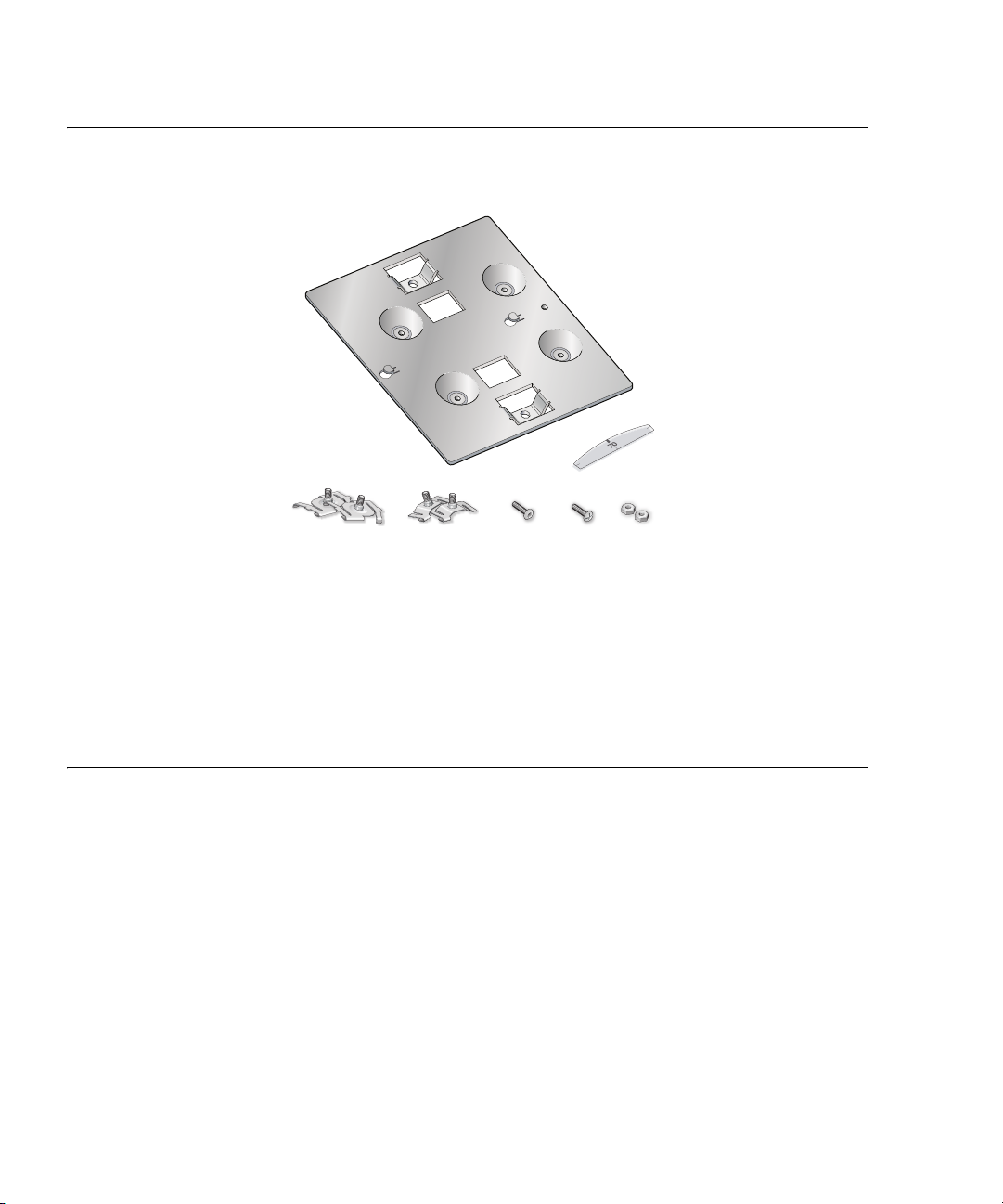
Kit Components
The following items are included in the AP70-MNT:
AP Mounting Cradle
Cover Label
15/16" T-Rail Clips 9/16" T-Rail Clips Nuts
Torx Screw
Pan head
Screw
FIGURE 1 Kit Items
Inform your supplier if there are any incorrect, missing or damaged parts. If
possible, retain the original packing materials. Use them to repack the product
in case there is a need to return it.
Prerequisites
Before using the mounting kit, you must first perform the initial AP
provisioning as described in the A70 Wireless Access/Grid Point Installation
Guide. When handling the AP, be sure to follow the requirements and safety
precautions outlined in that manual.
2 Part 0500056-02 May 2005
Page 3
Mounting the AP Cradle
The mounting kit can be used to install the A70:
z On a solid wall, shelf, or ceiling surface (see page 3)
z Suspended from a tile ceiling (see page 4)
z On a vertical post (see page 5)
z From an office partition hanger (see page 6)
The following procedures describe mounting the AP cradle. The AP is then
inserted into the cradle as shown on page 7.
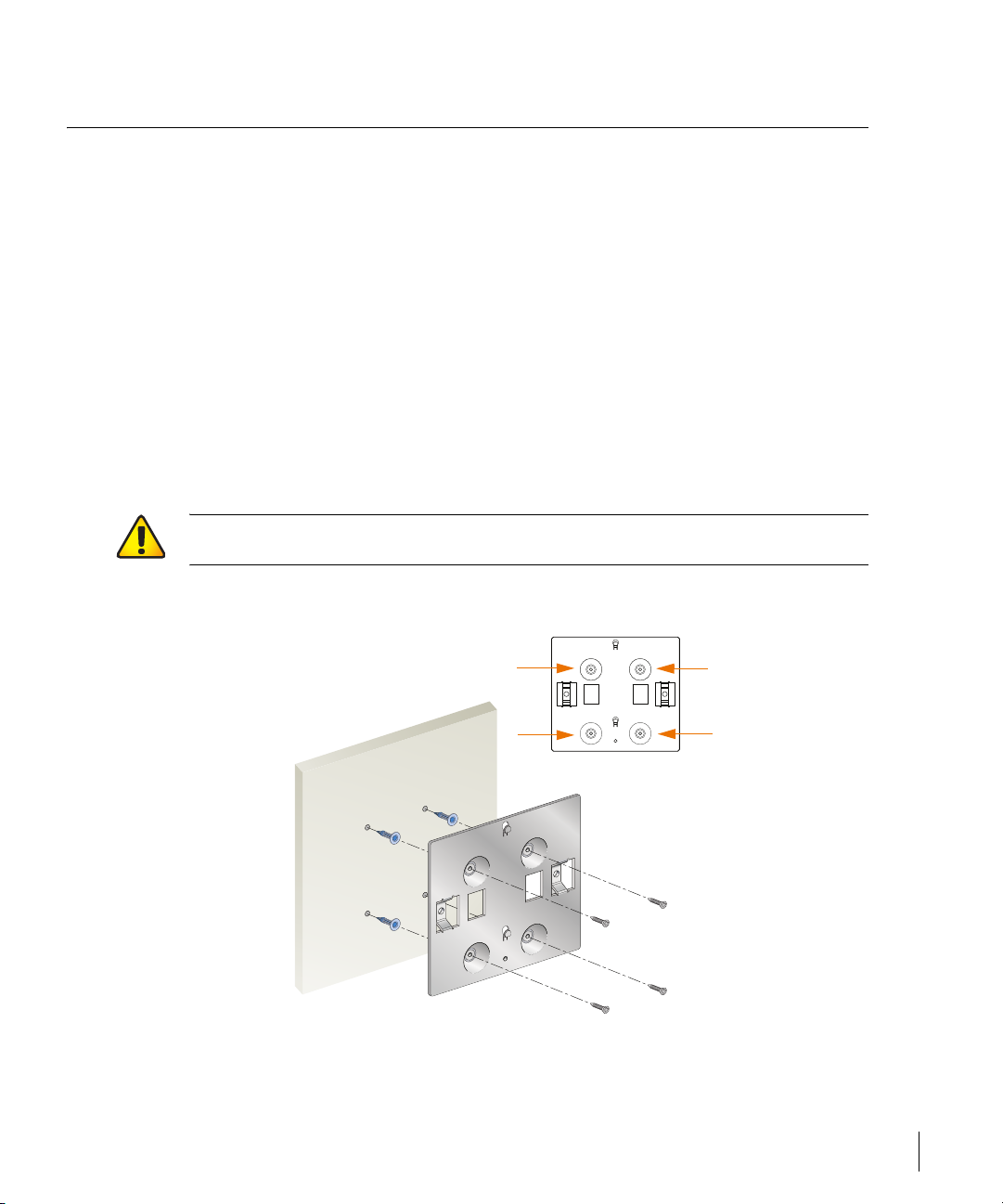
Solid Surface Mount
The mounting kit can be used to attach the AP to a solid, flat, indoor surface
such as a wall, shelf, and ceilings. (The holes used for surface mounting can
also be used to attach to any standard electrical gang box.)
CAUTION—For suspended ceilings, use only T-rail clips as described on
page 4.
FIGURE 2 Attaching the Cradle to a Solid Surface
The A70 Mounting Kit Installation Notes 3
Page 4
AP70-MNT: Installation Notes
Orient the cradle with its flat side against the mounting surface. If attaching the
cradle to a wall, orient it with the notched end at the top.
Secure the cradle to the solid surface using four #6 screws (not included) or
equivalent.
Suspended Ceiling Mount
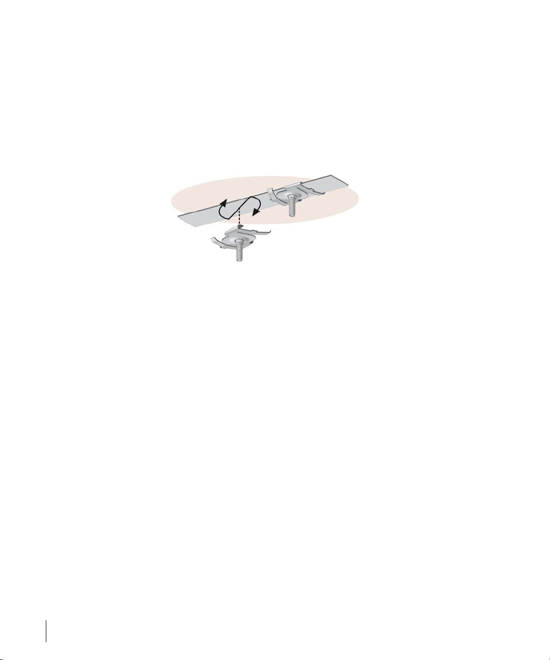
1 Attach the T-rail clips to the ceiling rail.
FIGURE 3 Attaching the T-Rail Clips
The T-rail clips twist onto the ceiling rails used with standard suspended-ceiling
systems. Use either the 15/16-inch or 9/16-inch clips, as appropriate for your
ceiling. Place the T-rail clips approximately 5.5 cm (2-1/8 inches) apart at the
location where the AP will be installed. Use the mounting cradle to gauge the
appropriate separation.
4 Part 0500056-02 May 2005
Page 5

2 Attach the cradle to the T-rail clips.
Side View
T-Rail
Clip
Cradle
Nut
FIGURE 4 Mounting the Cradle to a Suspended Ceiling
Secure the cradle on each T-rail clip bolt using the remaining nuts.
Vertical Post Mount
FIGURE 5 Mounting the Cradle to a Vertical Post
The A70 Mounting Kit Installation Notes 5
Page 6

AP70-MNT: Installation Notes
To mount the AP to a vertical post, thread a metal or plastic mounting strap
(not included) around the post and through the large slots on the cradle. The
strap should be flat and no wider than 1.5 cm (5/8 inches).
Office Partition Mount
FIGURE 6 Mounting the Cradle to a Partition Hanger
The cradle includes mounting holes for a variety of different office partition
hangers (not included). Use the hole most suited for your particular hanger
system’s hook or bolt.
6 Part 0500056-02 May 2005
Page 7

Placing the AP into the Cradle
3 Remove the label from the front of the AP chassis.
FIGURE 7 Removing the Label
The label conceals a mounting hole required in a later step. The extra label
shipped with the mounting kit is designed to replace this label once it is
removed.
The A70 Mounting Kit Installation Notes 7
Page 8

AP70-MNT: Installation Notes
4 Place the AP into the mounting cradle.
FIGURE 8 Placing the A70 into the Cradle
Fit the keyhole-shaped slots on the rear of the AP chassis over the cradle
mounting pin and tab. Slide the AP chassis downward so that the AP slot
captures the tab.
8 Part 0500056-02 May 2005
Page 9

5 Secure the AP with one of the included screws.
FIGURE 9 Installing the Cradle Screw
Use either the cross-head or hex-head screw. The hex-head screw requires a
less commonly available tool and may increase casual security. Install the
screw through the mounting hole in the front of the AP chassis (previously
covered by the label) and into the cradle mounting pin. Do not overtighten.
6 Apply the new label.
7 Secure the AP, if desired.
To prevent the unauthorized removal of the AP from its installed location, use a
Kensington MicroSaver Security Cable (not included). Wrap the security cable
around an immovable object, insert the cable’s lock into the Kensington
Security Slot on the back of the AP, and turn the key.
8 Orient the antennas.
For best performance, orient the antennas vertically.
9 Resume standard installation.
Once mounting is complete, connect the required cables and complete the
installation as described in the A70 Wireless Access/Grid Point Installation
Guide.
The A70 Mounting Kit Installation Notes 9
Page 10

AP70-MNT: Installation Notes
Notes
10 Part 0500056-02 May 2005
Page 11

Notes 11
Page 12

AP70-MNT: Installation Notes
12 Part 0500056-02 May 2005
 Loading...