

Page 1

AOS-W
User Guide
AOS-W Version 3.1
Page 2

Copyright
Copyright © 2007 Alcatel Internetworking, Inc. All rights reserved.
Specifications in this manual are subject to change without notice.
Originated in the USA.
Trademarks
AOS-W, Alcatel 4308, Alcatel 4324, Alcatel 6000, Alcatel 41, Alcatel 60/61/65,
Alcatel 70, and Alcatel 80 are trademarks of Alcatel Internetworking, Inc. in the
United States and certain other countries.
Any other trademarks appearing in this manual are the property of their respective
companies.
Legal Notice
The use of Alcatel Internetworking Inc. switching platforms and software, by all
individuals or corporations, to terminate Cisco or Nortel VPN client devices
constitutes complete acceptance of liability by that individual or corporation for
this action and indemnifies, in full, Alcatel Internetworking Inc. from any and all
legal actions that might be taken against it with respect to infringement of
copyright on behalf of Cisco Systems or Nortel Networks.
2 AOS-W 3.1 032063-00 Rev A
User Guide February 2007
Page 3

Contents
Preface . . . . . . . . . . . . . . . . . . . . . . . . . . . . . . . . . . . . . . . . . . . . . . . . . . 17
Document Organization. . . . . . . . . . . . . . . . . . . . . . . . . . . . . . . . . . . . . 17
Related Documents
Text Conventions
Contacting Alcatel
Volume 1
Introducing the Alcatel OmniAccess System
Chapter 1 Overview of the Alcatel OmniAccess System
Alcatel OmniAccess System Components . . . . . . . . . . . . . . . . . . . 24
Alcatel Access Points
Alcatel WLAN Switches
AOS-W
Basic WLAN Configuration
Authentication
Encryption
VLAN
User Role
Wireless Client Access to the WLAN
Association
Authentication
Client Mobility and AP Association
Configuring and Managing the Alcatel OmniAccess System
. . . . . . . . . . . . . . . . . . . . . . . . . . . . . . . . . . . . . . . . . . . . . . . . . . 31
. . . . . . . . . . . . . . . . . . . . . . . . . . . . . . . . . . . . . . . . . . . . . . . 35
. . . . . . . . . . . . . . . . . . . . . . . . . . . . . . . . . . . . . . . . . . . . . . . . . . . . 36
. . . . . . . . . . . . . . . . . . . . . . . . . . . . . . . . . . . . . . . . . . . . . . . . 38
. . . . . . . . . . . . . . . . . . . . . . . . . . . . . . . . . . . . . . . . . 17
. . . . . . . . . . . . . . . . . . . . . . . . . . . . . . . . . . . . . . . . . . 18
. . . . . . . . . . . . . . . . . . . . . . . . . . . . . . . . . . . . . . . . . . 19
. . . . . . . . . . . . . . . . . . . . . . . . . . . . . . . . . . . . 24
. . . . . . . . . . . . . . . . . . . . . . . . . . . . . . . . . . 28
. . . . . . . . . . . . . . . . . . . . . . . . . . . . . . . . . . 33
. . . . . . . . . . . . . . . . . . . . . . . . . . . . . . . . . . . . . . . . . . . 33
. . . . . . . . . . . . . . . . . . . . . . . . 39
. . . . . . . . . . . . . . . . . . . . . . . . . . . . . . . . . . . . . . . . . . . . . . 39
. . . . . . . . . . . . . . . . . . . . . . . . . . . . . . . . . . . . . . . . . . . 40
. . . . . . . . . . . . . . . . . . . . . . . . 41
. . 42
Volume 2
Installing the Alcatel OmniAccess System
Chapter 2 Deploying a Basic OmniAccess System
Configuration Overview. . . . . . . . . . . . . . . . . . . . . . . . . . . . . . . . . . . . . 46
Deployment Scenario #1
Deployment Scenario #2
Deployment Scenario #3
. . . . . . . . . . . . . . . . . . . . . . . . . . . . . . . . . 46
. . . . . . . . . . . . . . . . . . . . . . . . . . . . . . . . . 47
. . . . . . . . . . . . . . . . . . . . . . . . . . . . . . . . . 48
AOS-W 3.1 3
User Guide
Page 4

Contents
Configuring the Alcatel WLAN Switch . . . . . . . . . . . . . . . . . . . . . . . 50
Run the Initial Setup
Configure a VLAN for Network Connection
Connect the WLAN Switch to the Network
Configure the Loopback for the WLAN Switch
Deploying APs
Run Alcatel RF Plan
Enable APs to Connect to the WLAN Switch
Install APs
Update RF Plan
Additional Configuration
. . . . . . . . . . . . . . . . . . . . . . . . . . . . . . . . . . . . . . . . . . . . . 55
. . . . . . . . . . . . . . . . . . . . . . . . . . . . . . . . . . . . . . . . . . . . . . . 58
. . . . . . . . . . . . . . . . . . . . . . . . . . . . . . . . . . . . . . 50
. . . . . . . . . . . . . . . . . . . . . . . . . . . . . . . . . . . . . . 55
. . . . . . . . . . . . . . . . . . . . . . . . . . . . . . . . . . . . . . . . . . 59
. . . . . . . . . . . . . . . . . . . . . . . . . . . . . . . . . . . . 59
Chapter 3 Configuring Network Parameters
Configuring VLANs . . . . . . . . . . . . . . . . . . . . . . . . . . . . . . . . . . . . . . . . . 62
Configuring Ports
VLAN Assignment
Assigning a Static Address to a VLAN
Configuring a VLAN to Receive a Dynamic Address
Configuring Source NAT for VLAN Interfaces
Configuring Static Routes
Configuring the Loopback IP Address
. . . . . . . . . . . . . . . . . . . . . . . . . . . . . . . . . . . . . . . . 62
. . . . . . . . . . . . . . . . . . . . . . . . . . . . . . . . . . . . . . . 63
. . . . . . . . . . . . . . . . . . . . . . . . . . . . . . . . . . . 70
. . . . . . . . . . . . . . . . 51
. . . . . . . . . . . . . . . . 53
. . . . . . . . . . . . . 54
. . . . . . . . . . . . . . 55
. . . . . . . . . . . . . . . . . . . . . 64
. . . . . . . . 64
. . . . . . . . . . . . . . 68
. . . . . . . . . . . . . . . . . . . . . . . 71
Chapter 4 RF Plan
Overview . . . . . . . . . . . . . . . . . . . . . . . . . . . . . . . . . . . . . . . . . . . . . . . . . . 74
Before You Begin
Task Overview
Planning Requirements
Using RF Plan
Campus List Page
Building List Page
Building Specifications Overview Page
Building Dimension Page
AP Modeling Parameters Page
AM Modeling Page
Planning Floors Pages
AP Plan Page
AM Plan Page
Exporting and Importing Files
Locate
FQLN Mapper
4 AOS-W 3.1 032063-00 Rev A
User Guide February 2007
. . . . . . . . . . . . . . . . . . . . . . . . . . . . . . . . . . . . . . . . . . . . . . . . . . 100
. . . . . . . . . . . . . . . . . . . . . . . . . . . . . . . . . . . . . . . . . . . 75
. . . . . . . . . . . . . . . . . . . . . . . . . . . . . . . . . . . . . . . . . . . 75
. . . . . . . . . . . . . . . . . . . . . . . . . . . . . . . . . . . 75
. . . . . . . . . . . . . . . . . . . . . . . . . . . . . . . . . . . . . . . . . . . . . . 76
. . . . . . . . . . . . . . . . . . . . . . . . . . . . . . . . . . . . . . . . 76
. . . . . . . . . . . . . . . . . . . . . . . . . . . . . . . . . . . . . . . . 78
. . . . . . . . . . . . . . . . . . . . 79
. . . . . . . . . . . . . . . . . . . . . . . . . . . . . . . . . 80
. . . . . . . . . . . . . . . . . . . . . . . . . . . . 82
. . . . . . . . . . . . . . . . . . . . . . . . . . . . . . . . . . . . . . . 85
. . . . . . . . . . . . . . . . . . . . . . . . . . . . . . . . . . . . 87
. . . . . . . . . . . . . . . . . . . . . . . . . . . . . . . . . . . . . . . . . . . . 95
. . . . . . . . . . . . . . . . . . . . . . . . . . . . . . . . . . . . . . . . . . . 97
. . . . . . . . . . . . . . . . . . . . . . . . . . . . . 98
. . . . . . . . . . . . . . . . . . . . . . . . . . . . . . . . . . . . . . . . . . . 100
Page 5

RF Plan Example . . . . . . . . . . . . . . . . . . . . . . . . . . . . . . . . . . . . . . . . . . 103
Sample Building
Create a Building
Model the Access Points
Model the Air Monitors
Add and Edit a Floor
Defining Areas
Running the AP Plan
Running the AM Plan
. . . . . . . . . . . . . . . . . . . . . . . . . . . . . . . . . . . . . . . . . 103
. . . . . . . . . . . . . . . . . . . . . . . . . . . . . . . . . . . . . . . 104
. . . . . . . . . . . . . . . . . . . . . . . . . . . . . . . 105
. . . . . . . . . . . . . . . . . . . . . . . . . . . . . . . . . 106
. . . . . . . . . . . . . . . . . . . . . . . . . . . . . . . . . . . . 106
. . . . . . . . . . . . . . . . . . . . . . . . . . . . . . . . . . . . . . . . . . 107
. . . . . . . . . . . . . . . . . . . . . . . . . . . . . . . . . . . 110
. . . . . . . . . . . . . . . . . . . . . . . . . . . . . . . . . . . 112
Volume 3
Configuring APs
Chapter 5 Configuring Access Points
AP Configuration Overview . . . . . . . . . . . . . . . . . . . . . . . . . . . . . . . . 116
AP Names and Groups
Virtual APs
Configuring Profiles
Example Configurations
Configuring the Corpnet WLAN
Guest WLAN
Advanced Configuration Options
Channel Switch Announcement
. . . . . . . . . . . . . . . . . . . . . . . . . . . . . . . . . . . . . . . . . . . . . 120
. . . . . . . . . . . . . . . . . . . . . . . . . . . . . . . . . . . . . . . . . . . . 132
. . . . . . . . . . . . . . . . . . . . . . . . . . . . . . . . . . 116
. . . . . . . . . . . . . . . . . . . . . . . . . . . . . . . . . . . . . . . 121
. . . . . . . . . . . . . . . . . . . . . . . . . . . . . . . . . . . 126
. . . . . . . . . . . . . . . . . . . . . . . . . . 127
. . . . . . . . . . . . . . . . . . . . . . . . . . . 135
. . . . . . . . . . . . . . . . . . . . . . . . . 135
Contents
Chapter 6 Configuring Remote APs
Overview . . . . . . . . . . . . . . . . . . . . . . . . . . . . . . . . . . . . . . . . . . . . . . . . . 138
Configuring the Secure Remote Access Point Service
Configure a Public IP Address for the WLAN Switch
Configure the VPN Server
Configure the Remote AP User Role
Configure VPN Authentication
Provision the AP
Deploying a Branch Office/Home Office Solution
Troubleshooting the Branch Office Configuration
Double Encryption
. . . . . . . . . . . . . . . . . . . . . . . . . . . . . . . . . . . . . . . . 145
. . . . . . . . . . . . . . . . . . . . . . . . . . . . . . . . . . . . . . . . . 148
. . . . . . . . . . . . . . . . . . . . . . . . . . . . . . . 141
. . . . . . . . . . . . . . . . . . . . . . 142
. . . . . . . . . . . . . . . . . . . . . . . . . . . 144
. . . . . . . 140
. . . . . . 140
. . . . . . . . . . . . 146
. . . . . . . . . 148
Volume 4
Configuring Wireless Encryption and Authentication
AOS-W 3.1 5
User Guide
Page 6

Contents
Chapter 7 Configuring Roles and Policies
Policies . . . . . . . . . . . . . . . . . . . . . . . . . . . . . . . . . . . . . . . . . . . . . . . . . . . 152
Access Control Lists (ACLs)
Creating a Firewall Policy
Creating a User Role
Assigning User Roles
Default User Role in AAA Profile
User-Derived Role
Default Role for Authentication Method
Server-Derived Role
VSA-Derived Role
Firewall Parameters
. . . . . . . . . . . . . . . . . . . . . . . . . . . . . . . . . . . . . . . 156
. . . . . . . . . . . . . . . . . . . . . . . . . . . . . . . . . . . . . . 160
. . . . . . . . . . . . . . . . . . . . . . . . . . . . . . . . . . . . . . . 161
. . . . . . . . . . . . . . . . . . . . . . . . . . . . . . . . . . . . . 164
. . . . . . . . . . . . . . . . . . . . . . . . . . . . . . . . . . . . . . . 165
. . . . . . . . . . . . . . . . . . . . . . . . . . . . . . . . . . . . . . . 166
. . . . . . . . . . . . . . . . . . . . . . . . . . . . . 152
. . . . . . . . . . . . . . . . . . . . . . . . . . . . . . . . . . 153
. . . . . . . . . . . . . . . . . . . . . . . . . 160
Chapter 8 Configuring Authentication Servers
Servers and Server Groups . . . . . . . . . . . . . . . . . . . . . . . . . . . . . . . . 170
Configuring Servers
Configuring a RADIUS Server
Configuring an LDAP Server
Configuring a TACACS+ Server
Configuring the Internal Database
Configuring Server Groups
Configuring Server Rules
Assigning Server Groups
Configuring Authentication Timers
. . . . . . . . . . . . . . . . . . . . . . . . . . . . . . . . . . . . . . . 171
. . . . . . . . . . . . . . . . . . . . . . . . . . . . 171
. . . . . . . . . . . . . . . . . . . . . . . . . . . . . 173
. . . . . . . . . . . . . . . . . . . . . . . . . . 174
. . . . . . . . . . . . . . . . . . . . . . . . 175
. . . . . . . . . . . . . . . . . . . . . . . . . . . . . . . . . 177
. . . . . . . . . . . . . . . . . . . . . . . . . . . . . . . . 177
. . . . . . . . . . . . . . . . . . . . . . . . . . . . . . . . 180
. . . . . . . . . . . . . . . . . . . . . . . . . 182
. . . . . . . . . . . . . . . . . . 163
Chapter 9 Configuring 802.1x Authentication
Overview of 802.1x Authentication. . . . . . . . . . . . . . . . . . . . . . . . . 186
Authentication with a RADIUS Server
Authentication Terminated on WLAN Switch
Configuring 802.1x Authentication
802.1x Authentication Profile
Configuring User and Computer Authentication
Example Configurations
Authentication with an 802.1x RADIUS Server
Authentication with the WLAN Switch’s Internal Database
Advanced Configuration Options for 802.1x
Reauthentication with Unicast Key Rotation
. . . . . . . . . . . . . . . . . . . . . . . . . . . . . . . . . . . 196
. . . . . . . . . . . . . . . . . . . . . . . . . . . . 191
. . . . . . . . . . . . . . . . . . . . 187
. . . . . . . . . . . . . 188
. . . . . . . . . . . . . . . . . . . . . . . . . 190
. . . . . . . . . . 193
. . . . . . . . . . . . 196
211
. . . . . . . . . . . . . . . . 224
. . . . . . . . . . . . . . 224
Chapter 10 Configuring Captive Portal
Overview of Captive Portal Functions . . . . . . . . . . . . . . . . . . . . . . 228
Policy Enforcement Firewall License
WLAN Switch Server Certificate
Configuring Captive Portal in the Base AOS-W
6 AOS-W 3.1 032063-00 Rev A
User Guide February 2007
. . . . . . . . . . . . . . . . . . . . . 228
. . . . . . . . . . . . . . . . . . . . . . . . . 228
. . . . . . . . . . . . . . 229
Page 7

Configuring Captive Portal with the Policy Enforcement Firewall
License
Example Authentication with Captive Portal
Configuring Policies and Roles
Configuring the Guest VLAN
Configuring Captive Portal Authentication
Modifying the Initial User Role
Configuring the AAA Profile
Configuring the WLAN
User Account Administration
Captive Portal Configuration Parameters
Optional Captive Portal Configurations
Per-SSID Captive Portal Page
Changing the Protocol to HTTP
Proxy Server Redirect
Redirecting Clients on Different VLANs
Web Client Configuration with Proxy Script
Personalizing the Captive Portal Page
. . . . . . . . . . . . . . . . . . . . . . . . . . . . . . . . . . . . . . . . . . . . . . . . . . . 233
. . . . . . . . . . . . . . . . 236
. . . . . . . . . . . . . . . . . . . . . . . . . . . 237
. . . . . . . . . . . . . . . . . . . . . . . . . . . . . 245
. . . . . . . . . . . . . . . . 246
. . . . . . . . . . . . . . . . . . . . . . . . . . . 247
. . . . . . . . . . . . . . . . . . . . . . . . . . . . . 247
. . . . . . . . . . . . . . . . . . . . . . . . . . . . . . . . . . 248
. . . . . . . . . . . . . . . . . . . . . . . . . . . . 249
. . . . . . . . . . . . . . . . . . . . 250
. . . . . . . . . . . . . . . . . . . . . 253
. . . . . . . . . . . . . . . . . . . . . . . . . . . . 253
. . . . . . . . . . . . . . . . . . . . . . . . . . 254
. . . . . . . . . . . . . . . . . . . . . . . . . . . . . . . . . . . 255
. . . . . . . . . . . . . . . . . . . 257
. . . . . . . . . . . . . . 257
. . . . . . . . . . . . . . . . . . . . . . 259
Chapter 11 Configuring Virtual Private Networks
VPN Configuration . . . . . . . . . . . . . . . . . . . . . . . . . . . . . . . . . . . . . . . . 262
Configuring VPN with L2TP IPSec
Configuring VPN with PPTP
Configuring Alcatel Dialer
Captive Portal Download of Dialer
Configuring Site-to-Site VPN
Dead Peer Detection
. . . . . . . . . . . . . . . . . . . . . . . . . . . . . . . 266
. . . . . . . . . . . . . . . . . . . . . . . . . . . . . . . . . . 267
. . . . . . . . . . . . . . . . . . . . . . . . . . . . . . . . . . . . 271
. . . . . . . . . . . . . . . . . . . . . . . . . . 263
. . . . . . . . . . . . . . . . . . . . . . . 268
. . . . . . . . . . . . . . . . . . . . . . . . . . . . . . . 269
Contents
Chapter 12 Configuring Advanced Security
Overview . . . . . . . . . . . . . . . . . . . . . . . . . . . . . . . . . . . . . . . . . . . . . . . . . 274
Securing Client Traffic
Securing Wireless Clients
Securing Wired Clients
Securing Wireless Clients Through Non-Alcatel APs
Securing WLAN Switch-to-WLAN Switch Communication
Configuring the Odyssey Client on Client Machines
. . . . . . . . . . . . . . . . . . . . . . . . . . . . . . . . . . . . . 275
. . . . . . . . . . . . . . . . . . . . . . . . . . . . . . . 275
. . . . . . . . . . . . . . . . . . . . . . . . . . . . . . . . . . 278
. . . . . . 280
. . . . . . . . . 284
Chapter 13 Configuring MAC-Based Authentication
Configuring MAC-Based Authentication . . . . . . . . . . . . . . . . . . . . 290
Configuring the MAC Authentication Profile
Configuring Clients
. . . . . . . . . . . . . . . . . . . . . . . . . . . . . . . . . . . . . . . . 292
. . . . . . . . . . . . . . 290
AOS-W 3.1 7
User Guide
. . . 282
Page 8

Contents
Volume 5
Configuring Multiple
WLAN Switch Environments
Chapter 14 Adding Local WLAN Switches
Moving to a Multi-WLAN Switch Environment . . . . . . . . . . . . . . 296
Preshared Key for Inter-WLAN Switch Communication
Configuring Local WLAN Switches
Configuring the Local WLAN Switch
Configuring Layer-2/Layer-3 Settings
Configuring Trusted Ports
Configuring APs
. . . . . . . . . . . . . . . . . . . . . . . . . . . . . . . . . . . . . . . . 300
. . . . . . . . . . . . . . . . . . . . . . . . . . . . . . . 300
Chapter 15 Configuring IP Mobility
Alcatel Mobility Architecture . . . . . . . . . . . . . . . . . . . . . . . . . . . . . . . 304
Configuring Mobility Domains
Configuring a Mobility Domain
Joining a Mobility Domain
Example Configuration
Tracking Mobile Users
Mobile Client Roaming Status
Mobile Client Roaming Locations
Advanced Configuration
Proxy Mobile IP
Proxy DHCP
Revocations
. . . . . . . . . . . . . . . . . . . . . . . . . . . . . . . . . . . . . . . . . . . . 314
. . . . . . . . . . . . . . . . . . . . . . . . . . . . . . . . . . . . . . . . . . . . 314
. . . . . . . . . . . . . . . . . . . . . . . . . . . . . . . . . . . . . 311
. . . . . . . . . . . . . . . . . . . . . . . . . . . . . . . . . . . 313
. . . . . . . . . . . . . . . . . . . . . . . . . . . . . . . . . . . . . . . . . 313
. . . . . . . . . . . . . . . . . . . . . . . . . . . . . . 305
. . . . . . . . . . . . . . . . . . . . . . . . . . . 306
. . . . . . . . . . . . . . . . . . . . . . . . . . . . . . . 308
. . . . . . . . . . . . . . . . . . . . . . . . . . . . . . . . . . 308
. . . . . . . . . . . . . . . . . . . . . . . . . . . 311
. . . . 296
. . . . . . . . . . . . . . . . . . . . . . . . . 298
. . . . . . . . . . . . . . . . . . . . . 298
. . . . . . . . . . . . . . . . . . . . 299
. . . . . . . . . . . . . . . . . . . . . . . . 313
Chapter 16 Configuring Redundancy
Virtual Router Redundancy Protocol . . . . . . . . . . . . . . . . . . . . . . . . 316
Configuring Redundancy
Configuring Local WLAN Switch Redundancy
Master WLAN Switch Redundancy
Master-Local WLAN Switch Redundancy
. . . . . . . . . . . . . . . . . . . . . . . . . . . . . . . . . . . 317
. . . . . . . . . . . . 318
. . . . . . . . . . . . . . . . . . . . . . . 319
. . . . . . . . . . . . . . . . . 321
Volume 6
Configuring Intrusion Protection
8 AOS-W 3.1 032063-00 Rev A
User Guide February 2007
Page 9

Chapter 17 Configuring Wireless Intrusion Prevention
IDS Features . . . . . . . . . . . . . . . . . . . . . . . . . . . . . . . . . . . . . . . . . . . . . . 328
Unauthorized Device Detection
Denial of Service (DoS) Detection
Impersonation Detection
Signature Detection
IDS Configuration
IDS Profile Hierarchy
Configuring the IDS General Profile
Configuring Denial of Service Attack Detection
Configuring Impersonation Detection
Configuring Signature Detection
Configuring Unauthorized Device Detection
Client Blacklisting
Methods of Blacklisting
Blacklist Duration
Removing a Client from Blacklisting
. . . . . . . . . . . . . . . . . . . . . . . . . . . . . . . . . . . . . . . . . 332
. . . . . . . . . . . . . . . . . . . . . . . . . . . . . . . . . . . . . . . . . 354
. . . . . . . . . . . . . . . . . . . . . . . . . . . . . . . . . . . . . . . 356
. . . . . . . . . . . . . . . . . . . . . . . . . . . . . . . . 330
. . . . . . . . . . . . . . . . . . . . . . . . . . . . . . . . . . . . . 331
. . . . . . . . . . . . . . . . . . . . . . . . . . . . . . . . . . . . 332
. . . . . . . . . . . . . . . . . . . . . . . . . . . . . . . . . 354
. . . . . . . . . . . . . . . . . . . . . . . . . . 328
. . . . . . . . . . . . . . . . . . . . . . . . 330
. . . . . . . . . . . . . . . . . . . . . . 333
. . . . . . . . . . . 335
. . . . . . . . . . . . . . . . . . . . 338
. . . . . . . . . . . . . . . . . . . . . . . . . 341
. . . . . . . . . . . . . . 344
. . . . . . . . . . . . . . . . . . . . . . 357
Volume 7
Managing the OmniAccess System
Contents
Chapter 18 Configuring Management Access
Management Interfaces. . . . . . . . . . . . . . . . . . . . . . . . . . . . . . . . . . . . 362
Web Access
CLI Access
Alcatel Mobility Manager
Managing Certificates
About Digital Certificates
Obtaining a Server Certificate
Obtaining a Client Certificate
Importing Certificates
Updating CRLs
Service-Specific Use of Certificates
Configuring SNMP
SNMP for the WLAN Switch
SNMP for Access Points
SNMP Traps
Configuring Logging
Creating Guest Accounts
Configuring the Guest Provisioning User
Guest-Provisioning User Tasks
Optional Configurations
. . . . . . . . . . . . . . . . . . . . . . . . . . . . . . . . . . . . . . . . . . . . 363
. . . . . . . . . . . . . . . . . . . . . . . . . . . . . . . . . . . . . . . . . . . . . 367
. . . . . . . . . . . . . . . . . . . . . . . . . . . . . . . . 371
. . . . . . . . . . . . . . . . . . . . . . . . . . . . . . . . . . . . . 373
. . . . . . . . . . . . . . . . . . . . . . . . . . . . . . . . 373
. . . . . . . . . . . . . . . . . . . . . . . . . . . . 374
. . . . . . . . . . . . . . . . . . . . . . . . . . . . 375
. . . . . . . . . . . . . . . . . . . . . . . . . . . . . . . . . . . 375
. . . . . . . . . . . . . . . . . . . . . . . . . . . . . . . . . . . . . . . . . . 377
. . . . . . . . . . . . . . . . . . . . . . 378
. . . . . . . . . . . . . . . . . . . . . . . . . . . . . . . . . . . . . . . . 381
. . . . . . . . . . . . . . . . . . . . . . . . . . . . . 381
. . . . . . . . . . . . . . . . . . . . . . . . . . . . . . . . 383
. . . . . . . . . . . . . . . . . . . . . . . . . . . . . . . . . . . . . . . . . . . . 385
. . . . . . . . . . . . . . . . . . . . . . . . . . . . . . . . . . . . . . . 391
. . . . . . . . . . . . . . . . . . . . . . . . . . . . . . . . . . 393
. . . . . . . . . . . . . . . . . 393
. . . . . . . . . . . . . . . . . . . . . . . . . . 394
. . . . . . . . . . . . . . . . . . . . . . . . . . . . . . . . . 395
AOS-W 3.1 9
User Guide
Page 10

Contents
Setting the System Clock . . . . . . . . . . . . . . . . . . . . . . . . . . . . . . . . . . 396
Manually Setting the Clock
Configuring an NTP Server
. . . . . . . . . . . . . . . . . . . . . . . . . . . . . . 396
. . . . . . . . . . . . . . . . . . . . . . . . . . . . . . 397
Chapter 19 Managing Software Feature Licenses
Alcatel Software Licenses . . . . . . . . . . . . . . . . . . . . . . . . . . . . . . . . . 400
Software License Types
The Software Licensing Process
Obtaining a Software License Certificate
Software License Certificates
Locating the System Serial Number
Obtaining a Software License Key
Applying the Software License Key
Additional Software License Information
Permanent Licenses
Evaluation Licenses
Deleting a License Key
Moving Licenses
Resetting the WLAN Switch
Getting Help with Licenses
. . . . . . . . . . . . . . . . . . . . . . . . . . . . . . . . . . . . . . . . 406
. . . . . . . . . . . . . . . . . . . . . . . . . . . . . . . . . 400
. . . . . . . . . . . . . . . . . . . . . . . . . . . 401
. . . . . . . . . . . . . . . . . 401
. . . . . . . . . . . . . . . . . . . . . . . . . . . . 402
. . . . . . . . . . . . . . . . . . . . . . 403
. . . . . . . . . . . . . . . . . . . . . . . 403
. . . . . . . . . . . . . . . . . . . . . . 404
. . . . . . . . . . . . . . . . . . . . 405
. . . . . . . . . . . . . . . . . . . . . . . . . . . . . . . . . . . . . 405
. . . . . . . . . . . . . . . . . . . . . . . . . . . . . . . . . . . . . 405
. . . . . . . . . . . . . . . . . . . . . . . . . . . . . . . . . . 406
. . . . . . . . . . . . . . . . . . . . . . . . . . . . . 406
. . . . . . . . . . . . . . . . . . . . . . . . . . . . . . . . 407
Volume 8
Configuring Advanced Services
Chapter 20 Configuring QoS for Voice
Roles and Policies for Voice Traffic . . . . . . . . . . . . . . . . . . . . . . . . . 412
Configuring a User Role for SIP Phones
Configuring a User Role for SVP Phones
Configuring a User Role for Vocera Badges
Configuring a User Role for SCCP Phones
Configuring User-Derivation Rules
Optional Configurations
Wi-Fi Multimedia
Battery Boost
WPA Fast Handover
. . . . . . . . . . . . . . . . . . . . . . . . . . . . . . . . . . . . . . . . . . . 425
. . . . . . . . . . . . . . . . . . . . . . . . . . . . . . . . . . . 424
. . . . . . . . . . . . . . . . . . . . . . . . . . . . . . . . . . . . . . . . 424
. . . . . . . . . . . . . . . . . . . . . . . . . . . . . . . . . . . . . 426
. . . . . . . . . . . . . . . . . . . . . . . 422
. . . . . . . . . . . . . . . . . . 412
. . . . . . . . . . . . . . . . . 415
. . . . . . . . . . . . . . . 417
. . . . . . . . . . . . . . . . 420
10 AOS-W 3.1 032063-00 Rev A
User Guide February 2007
Page 11

Voice Services Module Features. . . . . . . . . . . . . . . . . . . . . . . . . . . . 428
Configuring the VoIP CAC Profile
Dynamic WMM Queue Management
TSPEC Signaling Enforcement
WMM Queue Content Enforcement
Voice-Aware 802.1x
SIP Authentication Tracking
SIP Call Setup Keepalive
Mobile IP Home Agent Assignment
. . . . . . . . . . . . . . . . . . . . . . . . . . . . . . . . . . . . 433
. . . . . . . . . . . . . . . . . . . . . . . . . . . . . . . . . 435
. . . . . . . . . . . . . . . . . . . . . . . . 428
. . . . . . . . . . . . . . . . . . . . . 430
. . . . . . . . . . . . . . . . . . . . . . . . . . . 432
. . . . . . . . . . . . . . . . . . . . . . 433
. . . . . . . . . . . . . . . . . . . . . . . . . . . . . 434
. . . . . . . . . . . . . . . . . . . . . . 435
Chapter 21 External Services Interface
Understanding ESI. . . . . . . . . . . . . . . . . . . . . . . . . . . . . . . . . . . . . . . . . 438
Understanding the ESI Syslog Parser
ESI Parser Domains
Peer WLAN Switches
Syslog Parser Rules
ESI Configuration Overview
Health-Check Method, Groups, and Servers
Redirection Policies and User Role
ESI Syslog Parser Domains and Rules
Monitoring Syslog Parser Statistics
Example Route-mode ESI Topology
Configuring the Example Routed ESI Topology
Example NAT-mode ESI Topology
Configuring the Example NAT-mode ESI Topology
Basic Regular Expression Syntax
Character-Matching Operators
Regular Expression Repetition Operators
Regular Expression Anchors
References
. . . . . . . . . . . . . . . . . . . . . . . . . . . . . . . . . . . . . . . . . . . . . 483
. . . . . . . . . . . . . . . . . . . . . . . . . . . . . . . . . . . . . 440
. . . . . . . . . . . . . . . . . . . . . . . . . . . . . . . . . . . 441
. . . . . . . . . . . . . . . . . . . . . . . . . . . . . . . . . . . . . 442
. . . . . . . . . . . . . . . . . . . . . . . . . . . . . . . . 443
. . . . . . . . . . . . . . . . . . . . . . . . . . . . . 482
. . . . . . . . . . . . . . . . . . . . . . . 440
. . . . . . . . . . . . . . . . . . . . . . . 448
. . . . . . . . . . . . . . . . . . . . . . 462
. . . . . . . . . . . . . . . . . . . . . . . . . 463
. . . . . . . . . . . . . . . . . . . . . . . . . . 474
. . . . . . . . . . . . . . . . . . . . . . . . . . . 481
. . . . . . . . . . . . . . . . . . . . . . . . . . . 481
Contents
. . . . . . . . . . . . . . 444
. . . . . . . . . . . . . . . . . . . . 452
. . . . . . . . . . . 464
. . . . . . . . 475
. . . . . . . . . . . . . . . . . 482
Volume 9
Appendices
Appendix A Configuring DHCP with Vendor-Specific
Options . . . . . . . . . . . . . . . . . . . . . . . . . . . . . . . . . . . . 487
Overview . . . . . . . . . . . . . . . . . . . . . . . . . . . . . . . . . . . . . . . . . . . . . . . . . 488
Windows-Based DHCP Server
Configuring Option 60
Configuring Option 43
Linux DHCP Servers
. . . . . . . . . . . . . . . . . . . . . . . . . . . . . . . . . . . 488
. . . . . . . . . . . . . . . . . . . . . . . . . . . . . . . . . . . 489
. . . . . . . . . . . . . . . . . . . . . . . . . . . . . . . . . . . . . . . 491
. . . . . . . . . . . . . . . . . . . . . . . . . . . . . 488
AOS-W 3.1 11
User Guide
Page 12

Contents
Appendix B External Firewall Configuration . . . . . . . . . . 493
Communication Between Alcatel Devices . . . . . . . . . . . . . . . . . . . 494
Network Management Access
Other Communications
. . . . . . . . . . . . . . . . . . . . . . . . . . . . . . . . . . . . 496
. . . . . . . . . . . . . . . . . . . . . . . . . . . . . 495
Appendix C Alcatel System Defaults . . . . . . . . . . . . . . . . 497
Basic System Defaults . . . . . . . . . . . . . . . . . . . . . . . . . . . . . . . . . . . . . 498
Firewall Defaults
Network Services
Policies
System Roles
Default Open Ports
. . . . . . . . . . . . . . . . . . . . . . . . . . . . . . . . . . . . . . . . . . . . . . . . . 499
. . . . . . . . . . . . . . . . . . . . . . . . . . . . . . . . . . . . . . . . . . 498
. . . . . . . . . . . . . . . . . . . . . . . . . . . . . . . . . . . . . . . 498
. . . . . . . . . . . . . . . . . . . . . . . . . . . . . . . . . . . . . . . . . . . 500
. . . . . . . . . . . . . . . . . . . . . . . . . . . . . . . . . . . . . . . . 501
Appendix D Windows Client Example Configuration for
802.1x . . . . . . . . . . . . . . . . . . . . . . . . . . . . . . . . . . . . . 505
Window XP Wireless Client Example Configuration . . . . . . . . . 505
Appendix E Internal Captive Portal . . . . . . . . . . . . . . . . . . 511
Creating a New Internal Web Page . . . . . . . . . . . . . . . . . . . . . . . . . 512
Basic HTML Example
Installing a New Captive Portal Page
Displaying Authentication Error Message
Reverting to the Default Captive Portal
Language Customization
Customizing the Welcome Page
Customizing the Pop-Up box
Customizing the Logged Out Box
. . . . . . . . . . . . . . . . . . . . . . . . . . . . . . . . . . . . 513
. . . . . . . . . . . . . . . . . . . . . . . 514
. . . . . . . . . . . . . . . . . . . 515
. . . . . . . . . . . . . . . . . . . . . 516
. . . . . . . . . . . . . . . . . . . . . . . . . . . . . . . . . . . 516
. . . . . . . . . . . . . . . . . . . . . . . . . . . . 522
. . . . . . . . . . . . . . . . . . . . . . . . . . . . . . . 524
. . . . . . . . . . . . . . . . . . . . . . . . . . 525
Index . . . . . . . . . . . . . . . . . . . . . . . . . . . . . . . . . . . . . . . . . . . . . . . . . . . 527
12 AOS-W 3.1 032063-00 Rev A
User Guide February 2007
Page 13

List of Tables
Text Conventions . . . . . . . . . . . . . . . . . . . . . . . . . . . . . . . . . . . . . . . . . . . .18
Table 1-1 Optional Software Modules . . . . . . . . . . . . . . . . . . . . . . . . . . . .31
Table 1-2 Encryption Options by Authentication Method . . . . . . . . . . . . . . 35
Table 5-3 Default AP Names . . . . . . . . . . . . . . . . . . . . . . . . . . . . . . . . . . .117
Table 5-4 AP Profiles . . . . . . . . . . . . . . . . . . . . . . . . . . . . . . . . . . . . . . . . . 121
Table 5-5 Profiles for Example Configuration . . . . . . . . . . . . . . . . . . . . . . 127
Table 7-6 Firewall Policy Rule Parameters . . . . . . . . . . . . . . . . . . . . . . . . . 153
Table 7-7 User Role Parameters . . . . . . . . . . . . . . . . . . . . . . . . . . . . . . . .156
Table 7-8 Conditions for User-Derived Role . . . . . . . . . . . . . . . . . . . . . . . . 161
Table 7-9 Conditions for Server-Derived Role . . . . . . . . . . . . . . . . . . . . . .165
Table 7-10 Firewall Parameters . . . . . . . . . . . . . . . . . . . . . . . . . . . . . . . . .166
Table 8-11 RADIUS Server Configuration Parameters . . . . . . . . . . . . . . . .171
Table 8-12 LDAP Server Configuration Parameters . . . . . . . . . . . . . . . . . .173
Table 8-13 TACACS+ Server Configuration Parameters . . . . . . . . . . . . . . .174
Table 8-14 Internal Database Configuration Parameters . . . . . . . . . . . . . .176
Table 8-15 Server Group Configuration Parameters . . . . . . . . . . . . . . . . .177
Table 8-16 Server Rule Configuration Parameters . . . . . . . . . . . . . . . . . . .178
Table 8-17 Server Types and Purposes . . . . . . . . . . . . . . . . . . . . . . . . . . .180
Table 8-18 Authentication Timers . . . . . . . . . . . . . . . . . . . . . . . . . . . . . . . 182
Table 9-19 802.1x Authentication Profile Basic WebUI Parameters . . . . . . 192
Table 9-20 User and Machine Authentication Scenarios . . . . . . . . . . . . . .194
Table 10-21 Captive Portal Authentication Profile Parameters . . . . . . . . . 250
Table 13-22 MAC Authentication Profile Configuration Parameters . . . . . 290
Table 16-23 VRRP Parameters . . . . . . . . . . . . . . . . . . . . . . . . . . . . . . . . . .317
Table 17-24 IDS Profiles . . . . . . . . . . . . . . . . . . . . . . . . . . . . . . . . . . . . . . 332
Table 17-25 IDS General Profile Configuration Parameters . . . . . . . . . . . .333
Table 17-26 IDS Denial of Service Profile Configuration Parameters . . . . .335
Table 17-27 IDS Rate Thresholds Profile Configuration Parameters . . . . . 337
Table 17-28 IDS Impersonation Profile Configuration Parameters . . . . . . . 339
Table 17-29 Predefined Signatures . . . . . . . . . . . . . . . . . . . . . . . . . . . . . . 341
Table 17-30 Signature Rule Attributes . . . . . . . . . . . . . . . . . . . . . . . . . . . .343
Table 17-31 IDS Unauthorized Device Profile Configuration Parameters . .344
Table 17-32 WMS Configuration Parameters . . . . . . . . . . . . . . . . . . . . . .348
Table 17-33 Valid SSIDs with Multi-Tenancy and Misconfigured AP
Protection . . . . . . . . . . . . . . . . . . . . . . . . . . . . . . . . . . . . . . . . . . . . . . . . . 352
Table 18-34 WebUI Tools . . . . . . . . . . . . . . . . . . . . . . . . . . . . . . . . . . . . .365
Table 18-35 Configuration Pages . . . . . . . . . . . . . . . . . . . . . . . . . . . . . . . 366
Table 18-36 Line Editing Keys . . . . . . . . . . . . . . . . . . . . . . . . . . . . . . . . . .369
Table 18-37 SNMP Parameters for the WLAN Switch . . . . . . . . . . . . . . . . 381
AOS-W 3.1 13
User Guide
Page 14

List of Tables
Table 18-38 SNMP Profile Configuration Parameters . . . . . . . . . . . . . . . . 383
Table 18-39 SNMP User Profile Configuration Parameters . . . . . . . . . . . . 384
Table 18-40 Software Modules . . . . . . . . . . . . . . . . . . . . . . . . . . . . . . . . . 391
Table 18-41 Logging Levels . . . . . . . . . . . . . . . . . . . . . . . . . . . . . . . . . . . .392
Table 20-42 WMM Access Category to 802.1D Priority Mapping . . . . . . . 424
Table 20-43 WMM Access Categories and 802.1d Tags . . . . . . . . . . . . . .431
Table 21-44 Character-matching operators in regular expressions . . . . . . 481
Table 21-45 Regular expression repetition operators . . . . . . . . . . . . . . . . .482
Table 21-46 Regular expression anchors . . . . . . . . . . . . . . . . . . . . . . . . . . 482
Table C-47 Default (Trusted) Open Ports . . . . . . . . . . . . . . . . . . . . . . . . . . 501
14 AOS-W 3.1 032063-00 Rev A
User Guide February 2007
Page 15

List of Figures
Figure 1-1 Connecting APs to the Alcatel WLAN Switch . . . . . . . . . . . . . . . 25
Figure 1-2 Alcatel APs Establish GRE Tunnels to the WLAN Switch . . . . . .26
Figure 1-3 Client Traffic is Tunneled to the WLAN Switch . . . . . . . . . . . . . . 27
Figure 1-4 Master and Local WLAN Switches . . . . . . . . . . . . . . . . . . . . . . . 30
Figure 1-5 VLANs for Wireless Clients Configured on WLAN Switch . . . . . 37
Figure 2-6 APs Connected to WLAN Switch . . . . . . . . . . . . . . . . . . . . . . . . 59
Figure 3-7 IP Address Assignment to VLAN via DHCP or PPPoE . . . . . . . . .65
Figure 3-8 Example: Source NAT using WLAN Switch IP Address . . . . . . . 69
Figure 5-9 AP Groups . . . . . . . . . . . . . . . . . . . . . . . . . . . . . . . . . . . . . . . . 118
Figure 5-10 Virtual AP Configurations Applied to the Same AP . . . . . . . . . 120
Figure 5-11 Applying AP Profiles to AP Groups . . . . . . . . . . . . . . . . . . . .123
Figure 5-12 Applying WLAN Profiles to AP Groups . . . . . . . . . . . . . . . . . . 124
Figure 5-13 Excluding a Virtual AP Profile from an AP . . . . . . . . . . . . . . . .124
Figure 6-14 Remote AP with a Private Network . . . . . . . . . . . . . . . . . . . . 138
Figure 6-15 Remote AP with WLAN Switch on Public Network . . . . . . . . 139
Figure 6-16 Remote AP with WLAN Switch Behind Firewall . . . . . . . . . . .139
Figure 6-17 Remote AP in a Multi-WLAN Switch Environment . . . . . . . . .139
Figure 8-18 Server Group . . . . . . . . . . . . . . . . . . . . . . . . . . . . . . . . . . . . .170
Figure 9-19 802.1x Authentication with RADIUS Server . . . . . . . . . . . . . . 187
Figure 9-20 802.1x Authentication with Termination on WLAN Switch . . . 188
Figure 10-21 Captive Portal in Base Operating System Example . . . . . . . . 230
Figure 11-22 Site-to-Site VPN Configuration Components . . . . . . . . . . . . 269
Figure 12-23 Wireless xSec Client Example . . . . . . . . . . . . . . . . . . . . . . . . 276
Figure 12-24 Wired xSec Client Example . . . . . . . . . . . . . . . . . . . . . . . . . .278
Figure 12-25 WLAN Switch-to-WLAN Switch xSec Example . . . . . . . . . . .282
Figure 12-26 The regedit Screen . . . . . . . . . . . . . . . . . . . . . . . . . . . . . . . .284
Figure 12-27 Modifying a regedit Policy . . . . . . . . . . . . . . . . . . . . . . . . . . 285
Figure 12-28 The Funk Odyssey Client Profile . . . . . . . . . . . . . . . . . . . . . .285
Figure 12-29 Certificate Information . . . . . . . . . . . . . . . . . . . . . . . . . . . . .286
Figure 12-30 Network Profile . . . . . . . . . . . . . . . . . . . . . . . . . . . . . . . . . . .287
Figure 15-31 Routing of Traffic to Mobile Client within Mobility Domain .305
Figure 15-32 Example Configuration: Campus-Wide Mobility . . . . . . . . . . 309
Figure 16-33 Redundant Topology: Master-Local Redundancy . . . . . . . . . 322
Figure 18-34 Creating a Guest Account . . . . . . . . . . . . . . . . . . . . . . . . . . 393
Figure 18-35 Guest Account Information . . . . . . . . . . . . . . . . . . . . . . . . . 393
Figure 18-36 Guest Provisioning Page . . . . . . . . . . . . . . . . . . . . . . . . . . . 394
Figure 21-37 The ESI-Fortinet Topology . . . . . . . . . . . . . . . . . . . . . . . . . . 438
Figure 21-38 Load Balancing Groups . . . . . . . . . . . . . . . . . . . . . . . . . . . . . 439
Figure 21-39 ESI Parser Domains . . . . . . . . . . . . . . . . . . . . . . . . . . . . . . . 440
AOS-W 3.1 15
User Guide
Page 16

List of Figures
Figure 21-40 Peer WLAN Switches . . . . . . . . . . . . . . . . . . . . . . . . . . . . . .441
Figure 21-41 The External Services View . . . . . . . . . . . . . . . . . . . . . . . . . . 444
Figure 21-42 The User Roles View . . . . . . . . . . . . . . . . . . . . . . . . . . . . . . .448
Figure 21-43 The Add Role View . . . . . . . . . . . . . . . . . . . . . . . . . . . . . . . . 448
Figure 21-44 Firewall Polices Choices . . . . . . . . . . . . . . . . . . . . . . . . . . . . 449
Figure 21-45 Firewall Policy Attributes . . . . . . . . . . . . . . . . . . . . . . . . . . . 449
Figure 21-46 Setting Firewall Policy Parameters . . . . . . . . . . . . . . . . . . . . 450
Figure 21-47 Selecting Parameters in Drop-down Lists . . . . . . . . . . . . . . .450
Figure 21-48 The External Services View . . . . . . . . . . . . . . . . . . . . . . . . . . 452
Figure 21-49 The Syslog Parser Domains View . . . . . . . . . . . . . . . . . . . . .453
Figure 21-50 The Add Domain View . . . . . . . . . . . . . . . . . . . . . . . . . . . . . 454
Figure 21-51 The Edit Domain View . . . . . . . . . . . . . . . . . . . . . . . . . . . . . 455
Figure 21-52 The Syslog Parser Rules View . . . . . . . . . . . . . . . . . . . . . . .456
Figure 21-53 The New Rule View . . . . . . . . . . . . . . . . . . . . . . . . . . . . . . .457
Figure 21-54 The Edit Rule View . . . . . . . . . . . . . . . . . . . . . . . . . . . . . . . .459
Figure 21-55 The Syslog Parser Rule Test View . . . . . . . . . . . . . . . . . . . .460
Figure 21-56 The Syslog Parser Statistics View . . . . . . . . . . . . . . . . . . . .462
Figure 21-57 Example Route-Mode Topology . . . . . . . . . . . . . . . . . . . . . . 463
Figure 21-58 The User Roles View . . . . . . . . . . . . . . . . . . . . . . . . . . . . . . .468
Figure 21-59 The Add Role View . . . . . . . . . . . . . . . . . . . . . . . . . . . . . . . . 468
Figure 21-60 Firewall Polices Choices . . . . . . . . . . . . . . . . . . . . . . . . . . . . 469
Figure 21-61 Firewall Policy Attributes . . . . . . . . . . . . . . . . . . . . . . . . . . . 469
Figure 21-62 Setting Firewall Policy Parameters . . . . . . . . . . . . . . . . . . . . 470
Figure 21-63 Selecting Parameters in Drop-down Lists . . . . . . . . . . . . . . .470
Figure 21-64 Example NAT-Mode Topology . . . . . . . . . . . . . . . . . . . . . . . 474
Figure A-65 Scope Options Dialog Box . . . . . . . . . . . . . . . . . . . . . . . . . . . 490
Figure A-66 DHCP Scope Values . . . . . . . . . . . . . . . . . . . . . . . . . . . . . . . . 490
Figure D-67 Wireless Networks . . . . . . . . . . . . . . . . . . . . . . . . . . . . . . . . . 506
Figure D-68 Networks to Access . . . . . . . . . . . . . . . . . . . . . . . . . . . . . . . .506
Figure D-69 Wireless Network Association . . . . . . . . . . . . . . . . . . . . . . . . 508
Figure D-70 Wireless Network Authentication . . . . . . . . . . . . . . . . . . . . . .509
Figure D-71 Protected EAP Properties . . . . . . . . . . . . . . . . . . . . . . . . . . . .510
Figure D-72 EAP MSCHAPv2 Properties . . . . . . . . . . . . . . . . . . . . . . . . . . 510
16 AOS-W 3.1 032063-00 Rev A
User Guide February 2007
Page 17

Preface
This preface includes the following information:
An overview of the contents of this manual
A list of related documentation for further reading
A key to the various text conventions used throughout this manual
Alcatel support and service information
Document Organization
This user guide includes instructions and examples for commonly-used wireless
LAN (WLAN) Switch configurations such as Virtual Private Networks (VPNs),
authentication, and redundancy.
Volume 1 contains an overview of the Alcatel OmniAccess system. Volume 2
describes how to install the Alcatel OmniAccess system in a wired network.
Volume 3 describes how to configure Alcatel access points (APs), including
remote APs. The remaining volumes of the user guide describe other features of
the Alcatel OmniAccess system.
Related Documents
The following items are part of the complete documentation for the Alcatel
OmniAccess system:
Alcatel WLAN Switch Installation Guides
Alcatel Access Point Installation Guides
Release Notes
AOS-W 3.1 17
User Guide
Page 18

Preface
Text Conventions
The following conventions are used throughout this manual to emphasize
important concepts:
TABLE 1 Text Conventions
Type Style Description
Italics This style is used to emphasize important terms and to mark
the titles of books.
System items This fixed-width font depicts the following:
Sample screen output
System prompts
Filenames, software devices, and specific commands
when mentioned in the text
Commands In the command examples, this bold font depicts text that
you must type exactly as shown.
<Arguments> In the command examples, italicized text within angle
brackets represents items that you should replace with
information appropriate to your specific situation. For
example:
# send <text message>
In this example, you would type “send” at the system
prompt exactly as shown, followed by the text of the
message you wish to send. Do not type the angle brackets.
[ Optional ] In the command examples, items enclosed in brackets are
optional. Do not type the brackets.
{ Item A | Item B } In the command examples, items within curled braces and
separated by a vertical bar represent the available choices.
Enter only one choice. Do not type the braces or bars.
18 AOS-W 3.1 032063-00 Rev A
User Guide February 2007
Page 19

Contacting Alcatel
Contact Center Online
Main Site http://www.alcatel.com/enterprise
Support Site http://eservice.ind.alcatel.com
Email support@ind.alcatel.com
Sales & Support Contact Center Telephone
North America 1-800-995-2696
Latin America 1-877-919-9526
Europe +33 (0) 38 85 56 92 9
Asia Pacific +65 6586 1555
Worldwide 1-818-880-3500
Preface
AOS-W 3.1 19
User Guide
Page 20

Preface
20 AOS-W 3.1 032063-00 Rev A
User Guide February 2007
Page 21

Volume 1
Introducing the
Alcatel
OmniAccess
System
AOS-W Version 3.1
Page 22

22 AOS-W 3.1 032063-00 Rev A
User Guide February 2007
Page 23

Overview of the Alcatel OmniAccess System
Wireless local area networks (WLANs) allow users of personal computers with
wireless network interface adapters to communicate with each other and connect
to existing wired networks. The Alcatel OmniAccess system allows you to
implement WLANs in enterprise environments with lower cost of deployment,
simplified management, and multiple layers of security.
This chapter describes the components and features of the Alcatel OmniAccess
system, in the following topics:
“Alcatel OmniAccess System Components” on page 24
“Basic WLAN Configuration” on page 33
“Wireless Client Access to the WLAN” on page 39
“Configuring and Managing the Alcatel OmniAccess System” on page 42
1
AOS-W 3.1 23
User Guide
Page 24

Overview of the Alcatel OmniAccess System
Chapter 1
Alcatel OmniAccess System Components
The Alcatel OmniAccess system consists of the following components:
Alcatel Access Points
Alcatel WLAN Switches
AOS-W
The following sections describe each of these components.
Alcatel Access Points
Alcatel Access Points (APs) operate exclusively with Alcatel WLAN Switches to
provide network access for wireless clients. Alcatel APs support Institute of
Electrical and Electronics Engineers (IEEE) 802.11a/b/g standards for wireless
systems.
OTE: Alcatel offers a range of APs that support various antenna types and
N
radio specifications. Refer to the Installation Guide for your Alcatel AP for
specific information about supported features.
An AP broadcasts its configured service set identifier (SSID), which corresponds
to a specific wireless local area network (WLAN). Wireless clients discover APs by
listening for broadcast beacons or by sending active probes to search for APs
with a specific SSID.
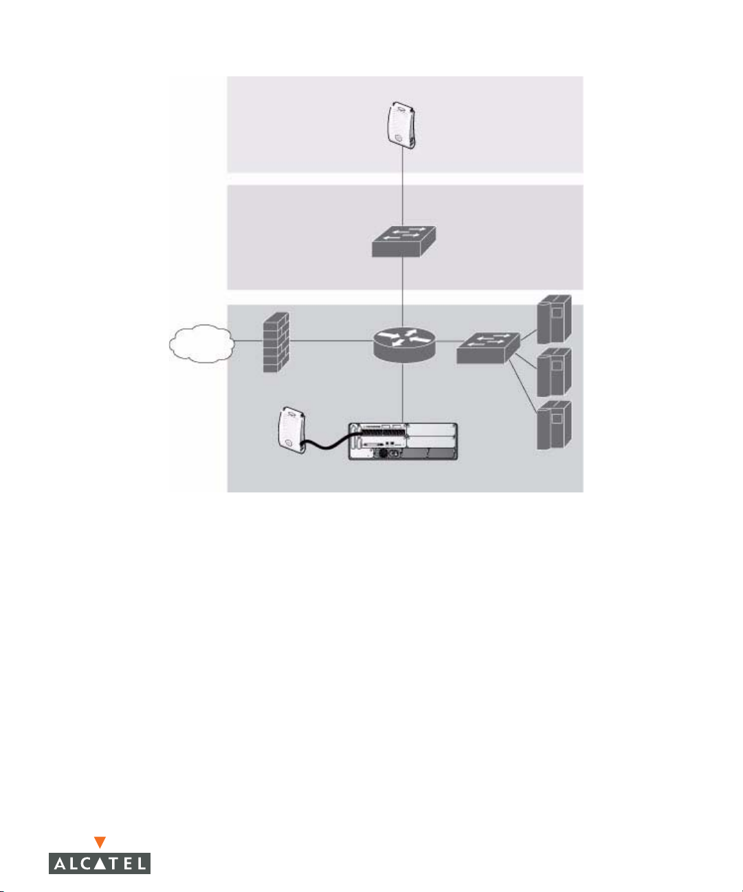
You can connect an Alcatel AP to an Alcatel WLAN Switch either directly with an
Ethernet cable or remotely through an IP network. Figure 1-1 shows two Alcatel
APs connected to an Alcatel WLAN Switch. One AP is connected to a switch in
the wiring closet that is connected to a router in the data center where the WLAN
Switch is located. The Ethernet port on the other AP is cabled directly to a port on
the WLAN Switch.
24 AOS-W 3.1 032063-00 Rev A
User Guide February 2007
Page 25
FLOOR
WIRING
CLOSET
INTERNET
Overview of the Alcatel OmniAccess System
ALCATEL AP CONNECTED
THROUGH AN IP NETWORK
Chapter 1
ALCATEL AP CONNECTED
WITH AN ETHERNET CABLE
ALCATEL WLAN SWITCH
DATA CENTER
FIGURE 1-1 Connecting APs to the Alcatel WLAN Switch
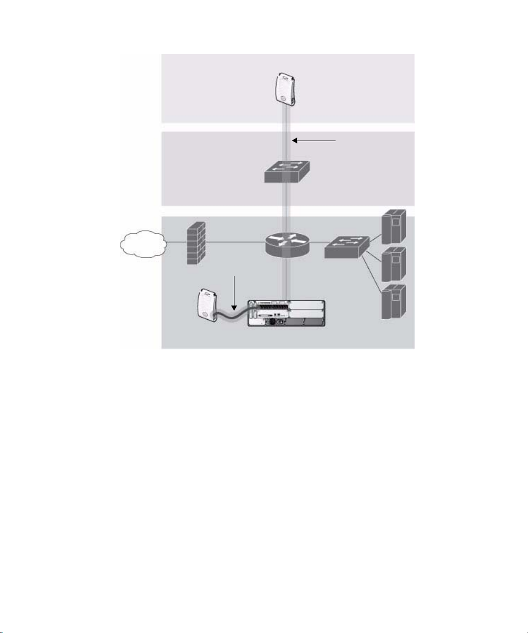
Alcatel APs are thin APs, which means their primary function is to receive and
transmit electromagnetic signals; other WLAN processing is left to the WLAN
Switch. When powered on, an Alcatel AP locates its host WLAN Switch through
a variety of methods, including the Alcatel Discovery Protocol (ADP), Domain
Name Service (DNS), or Dynamic Host Configuration Protocol (DHCP). When an
Alcatel AP locates its host WLAN Switch, it automatically builds a secure Generic
Routing Encapsulation (GRE) tunnel (Figure 1-2) to the WLAN Switch. The AP
then downloads its software and configuration from the WLAN Switch through
the tunnel.
AOS-W 3.1 25
User Guide
Page 26
Overview of the Alcatel OmniAccess System
Chapter 1
FLOOR
WIRING
CLOSET
INTERNET
GRE TUNNEL
ALCATEL AP
GRE T
UNNEL
ALCATEL WLAN SWITCH
DATA CENTER
FIGURE 1-2 Alcatel APs Establish GRE Tunnels to the WLAN Switch
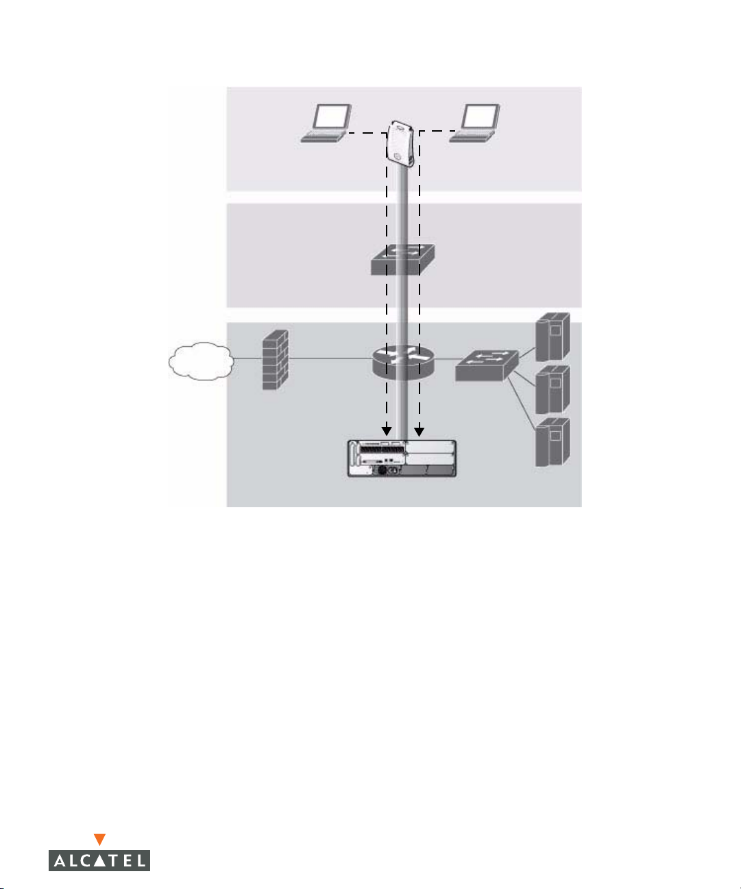
Client traffic received by the AP is immediately sent through the tunnel to the host
WLAN Switch (Figure 1-3), which performs packet processing such as encryption
and decryption, authentication, and policy enforcement.
26 AOS-W 3.1 032063-00 Rev A
User Guide February 2007
Page 27
FLOOR
WIRING
CLOSET
INTERNET
Overview of the Alcatel OmniAccess System
Chapter 1
WIRELESS CLIENTS
ALCATEL AP
DATA CENTER
ALCATEL WLAN SWITCH
FIGURE 1-3 Client Traffic is Tunneled to the WLAN Switch
Automatic RF Channel and Power Settings
Adaptive Radio Management (ARM) is a radio frequency (RF) resource allocation
algorithm that you can enable and configure in the Alcatel Mobility Edge system.
When ARM is enabled, each Alcatel AP can determine the optimum channel
selection and transmit power setting to minimize interference and maximize
coverage and throughput. The APs scan for better channels at periodic intervals
and report information to the WLAN Switch. The WLAN Switch analyzes reports
from all APs and coordinates changes, resulting in a higher performing RF
environment.
If an AP fails for any reason, the Alcatel OmniAccess system’s self-healing
mechanism automatically ensures coverage for wireless clients. The WLAN
Switch detects the failed AP and instructs neighboring APs to increase power
levels to compensate.
You can also enable the system to detect coverage holes, or areas where a good
RF signal is not adequately reaching wireless clients.
AOS-W 3.1 27
User Guide
Page 28

Overview of the Alcatel OmniAccess System
Chapter 1
RF Monitoring
An Alcatel AP can function as either a dedicated or shared Air Monitor (AM) to
monitor radio frequency (RF) spectrums to detect intrusions, denial of service
(DoS) attacks, and other vulnerabilities. A dedicated AM performs monitoring
functions exclusively and does not service wireless clients or advertise SSIDs. A
shared AM performs monitoring functions in addition to servicing wireless
clients.
Every AP automatically monitors the channel on which it services wireless clients.
You can configure the AP to perform off-channel scanning, where the AP spends
brief time intervals scanning other channels. However, the more clients an AP
services, the less time it has to perform off-channel scanning. If air monitoring
functions are critical to your network, Alcatel recommends that a few APs be
designated as dedicated AMs.
For example, you can configure dedicated AMs to perform the following
functions:
Detect, locate, and disable rogue APs (APs that are not authorized or
sanctioned by network administrators)
Detect and disable ad-hoc networks
Detect and disable honeypot APs
Detect wireless bridges
Capture remote packets
If air monitoring functions are only needed periodically, you can configure APs to
operate temporarily as AMs. You can also configure dedicated AMs to
automatically convert into APs if there is an AP failure or when there is high level
of traffic on the network.
Alcatel WLAN Switches
All Alcatel APs are connected either directly or remotely through an IP network to
an Alcatel WLAN Switch. The WLAN Switch is an enterprise-class switch that
bridges wireless client traffic to and from traditional wired networks and performs
high-speed Layer-2 or Layer-3 packet forwarding between Ethernet ports. While
Alcatel APs provide radio services only, the WLAN Switch performs upper-layer
media access control (MAC) processing, such as encryption and authentication,
as well as centralized configuration and management of SSIDs and RF
characteristics for Alcatel APs. This allows you to deploy APs with little or no
physical change to an existing wired infrastructure.
WLAN Switches provide 10/100 Mbps Fast Ethernet, IEEE 802.3af-compliant
ports that can provide Power over Ethernet (PoE) to directly-connected APs.
When you connect a PoE-capable port on the WLAN Switch to a PoE-compatible
device such as an Alcatel AP, the port automatically detects the device and
28 AOS-W 3.1 032063-00 Rev A
User Guide February 2007
Page 29

Overview of the Alcatel OmniAccess System
Chapter 1
provides operating power through the connected Ethernet cable. This allows APs
to be installed in areas where electrical outlets are unavailable, undesirable, or not
permitted, such as in the plenum or in air handling spaces.
OTE: Alcatel offers a range of WLAN Switches that provide different port types
N
and traffic capacities. Refer to the Installation Guide for your Alcatel
WLAN Switch for specific information about supported features.
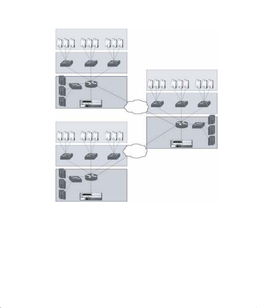
In an Alcatel OmniAccess system, at least one WLAN Switch is the master WLAN
Switch while non-master WLAN Switches are referred to as local WLAN Switches
(Figure 1-4). A master WLAN Switch offers a single point of configuration that is
automatically replicated from the master to local WLAN Switches throughout the
network.
Local WLAN Switches offer local points of traffic aggregation and management
for Alcatel APs and services. A local WLAN Switch can perform any supported
function (for example, WLAN management, policy enforcement, VPN services,
and so on), however these services are always configured on the master WLAN
Switch and are “pushed” to specified local WLAN Switches.
An Alcatel AP obtains its software image and configuration from a master WLAN
Switch; it can also be instructed by a master WLAN Switch to obtain its software
from a local WLAN Switch.
AOS-W 3.1 29
User Guide
Page 30
Overview of the Alcatel OmniAccess System
Chapter 1
LOCAL WLAN
S
WITCH
MASTER WLAN
SWITCH
LOCAL WLAN
SWITCH
FIGURE 1-4 Master and Local WLAN Switches
A typical OmniAccess system includes one master WLAN Switch, one or more
backup master WLAN Switches and any number of local WLAN Switches. It is
important to note that master WLAN Switches do not share information with
each other. Thus, APs that share roaming tables, security policies, and other
configurations should be managed by the same master WLAN Switch.
30 AOS-W 3.1 032063-00 Rev A
User Guide February 2007
Page 31

Overview of the Alcatel OmniAccess System
Chapter 1
AOS-W
AOS-W is a suite of mobility applications that runs on all Alcatel WLAN Switches
and allows you to configure and manage the wireless and mobile user
environment.
AOS-W consists of a base software package with optional software modules that
you can activate by installing the appropriate license key (Tab l e 1 -1 ). The base
AOS-W software includes the following functions:
Centralized configuration and management of APs
Wireless client authentication to an external authentication server or to the
WLAN Switch’s local database
Encryption
Mobility with fast roaming
RF management and analysis tools
TABLE 1-1 Optional Software Modules
Optional Software Module Description
Policy Enforcement
Firewall
Wireless Intrusion
Protection
VPN Server Enables WLAN Switches to provide Virtual Private
Provides identity-based security for wired and
wireless clients. Stateful firewall enables
classification based on client identity, device type,
location, and time of day, and provides
differentiated access for different classes of users.
Detects, classifies and limits designated wireless
security threats such as rogue APs, DoS attacks,
malicious wireless attacks, impersonations, and
unauthorized intrusions. Eliminates need for
separate system of RF sensors and security
appliances.
Networks (VPN) tunnel termination to local and
remote clients. Provides site-to-site VPN tunnels
between Alcatel WLAN Switches and third-party
VPN concentrators.
AOS-W 3.1 31
User Guide
Page 32

Overview of the Alcatel OmniAccess System
Chapter 1
TABLE 1-1 Optional Software Modules (Continued)
Optional Software Module Description
Remote AP Allows an Alcatel AP to be securely connected
from a remote location to a WLAN Switch across
the Internet. Allows the remote AP to be plugged
directly into an Internet-connected DSL router; a
WLAN Switch does not need to be installed at the
remote location.
There are three Remote AP licenses available that
allow the WLAN Switch to support a maximum of
6, 128, or 256 Remote APs.
xSec Enables support for xSec, a Federal Information
Processing Standard (FIPS)-certifiable Layer-2
encryption protocol.
Client Integrity Enables wireless and wired client remediation
services before network access is granted.
Integrates Sygate Technologies Sygate
On-Demand Agent (SODA).
External Services Interface
(ESI)
Supports automatic redirect of clients to external
devices that provide inline network services such
as anti-virus, intrusion detection system (IDS), and
content filtering.
Each optional module has a software license (either permanent or evaluation) that
you must install on an Alcatel WLAN Switch as a software license key. Contact
your sales account manager or authorized reseller to obtain software licenses.
OTE: After installing one or more software license keys, you must reboot the
N
Alcatel WLAN Switch for the new feature to become available.
32 AOS-W 3.1 032063-00 Rev A
User Guide February 2007
Page 33

Overview of the Alcatel OmniAccess System
Basic WLAN Configuration
You have a wide variety of options for authentication, encryption, access
management, and user rights when you configure a WLAN in the Alcatel
OmniAccess system. However, you must configure the following basic elements:
An SSID that uniquely identifies the WLAN
Layer-2 authentication to protect against unauthorized access to the WLAN
Layer-2 encryption to ensure the privacy and confidentiality of the data
transmitted to and from the network
A user role and virtual local area network (VLAN) for the authenticated client
This section describes authentication, encryption, VLAN, and user role
configuration in the Alcatel OmniAccess system.
Authentication
A wireless client must authenticate to the Alcatel OmniAccess system in order to
access WLAN resources. There are several types of Layer-2 security mechanisms
allowed by the IEEE 802.11 standard that you can employ in the OmniAccess
system, including those that require an external RADIUS authentication server:
Chapter 1
Authentication
Method
None (Also called open system authentication) This is the default
Description
authentication protocol. The client’s identity, in the form of the
Media Access Control (MAC) address of the wireless adapter
in the wireless client, is passed to the WLAN Switch.
Essentially any client requesting access to the WLAN is
authenticated.
AOS-W 3.1 33
User Guide
Page 34

Overview of the Alcatel OmniAccess System
Chapter 1
Authentication
Method
Description
IEEE 802.1x The IEEE 802.1x authentication standard allows for the use of
keys that are dynamically generated on a per-client basic (as
opposed to a static key that is the same on all devices in the
network).
OTE: The 802.1x standard requires the use of a RADIUS
N
authentication server. Most Lightweight Directory
Access Protocol (LDAP) servers do not support
802.1x.
With 802.1x authentication, a supplicant is the wireless client
that wants to gain access to the network and the device that
communicates with both the supplicant and the
authentication server is the authenticator. In the Alcatel
OmniAccess system, the WLAN Switch is the 802.1x
authenticator, relaying authentication requests between the
authentication server and the supplicant.
OTE: During the authentication process, the supplicant (the
N
wireless client) and the RADIUS authentication server
negotiate the type of Extensible Authentication
Protocol (EAP) they will use for the authentication
transaction. The EAP type is completely transparent
to the WLAN Switch and has no impact on its
configuration.
Wi-Fi Protected
Access (WPA)
WPA implements most of the IEEE 802.11i standard. It is
designed for use with an 802.1x authentication server (the
Wi-Fi Alliance refers to this mode as WPA-Enterprise). WPA
uses the Temporal Key Integrity Protocol (TKIP) to dynamically
change keys and RC4 stream cipher to encrypt data.
WPA in
pre-shared key
With WPA-PSK, all clients use the same key (the Wi-Fi Alliance
refers to this mode as WPA-Personal).
(PSK) mode
OTE: In PSK mode, users must enter a passphrase from
(WPA-PSK)
N
8-63 characters to access the network. PSK is
intended for home and small office networks where
operating an 802.1x authentication server is not
practical.
WPA2 WPA2 implements the full IEEE 802.11i standard. In addition
to WPA features, WPA2 provides Counter Mode with Cipher
Blocking Chaining Message Authentication Code Protocol
(CCMP) for encryption which uses the Advanced Encryption
Standard (AES) algorithm. (The Wi-Fi Alliance refers to this
mode as WPA2-Enterprise.)
34 AOS-W 3.1 032063-00 Rev A
User Guide February 2007
Page 35

Overview of the Alcatel OmniAccess System
Chapter 1
Authentication
Method
WPA2-PSK WPA2-PSK is WPA2 used in PSK mode, where all clients use
Description
the same key. (The Wi-Fi Alliance refers to this mode as
WPA2-Personal.)
Encryption
The Layer-2 encryption option you can select depends upon the authentication
method chosen (Tab l e 1 - 2).
TABLE 1-2 Encryption Options by Authentication Method
Authentication Method Encryption Option
None Null or Static WEP
802.1x Dynamic WEP
WPA or WPA-PSK only TKIP
WPA2 or WPA2-PSK only AES
Combination of WPA or WPA-PSK
and WPA2 or WPA2-PSK
You can configure the following data encryption options for the WLAN:
Mixed TKIP/AES
Encryption Method Description
Null Null means that no encryption is used and packets passing
between the wireless client and WLAN Switch are in clear
text.
Wired Equivalent
Protocol (WEP)
Defined by the original IEEE 802.11 standard, WEP uses
the RC4 stream cipher with 40-bit and 128-bit encryption
keys. The management and distribution of WEP keys is
performed outside of the 802.11 protocol. There are two
forms of WEP keys:
Static WEP requires you to manually enter the key for
each client and on the WLAN Switch.
Dynamic WEP allows the keys to be automatically
derived for each client for a specific authentication
method during the authentication process. Dynamic
WEP requires 802.1x authentication.
AOS-W 3.1 35
User Guide
Page 36

Overview of the Alcatel OmniAccess System
Chapter 1
Encryption Method Description
Temporal Key
Integrity Protocol
(TKIP)
Advanced
Encryption
Standard (AES)
Mixed
TKIP/AES-CCM
xSec (Extreme
Security)
TKIP ensures that the encryption key is changed for every
data packet. You specify TKIP encryption for WPA and
WPA-PSK authentication.
AES is an encryption cipher that uses the Counter-mode
CBC-MAC (Cipher Block Chaining-Message Authentication
Code) Protocol (CCMP) mandated by the IEEE 802.11i
standard. AES-CCMP is specifically designed for IEEE
802.11 encryption and encrypts parts of the 802.11 MAC
headers as well as the data payload. You can specify
AES-CCMP encryption with WPA2 or WPA2-PSK
authentication.
This option allows the WLAN Switch to use TKIP
encryption with WPA or WPA-PSK clients and use AES
encryption with WPA2 or WPA2-PSK clients. This option
allows you to deploy the Alcatel OmniAccess system in
environments that contain existing WLANs that use
different authentication and encryption.
xSec is a Federal Information Processing Standard
(FIPS)-certifiable Layer-2 encryption. xSec can encrypt and
tunnel Layer-2 traffic between a WLAN Switch and wired
and wireless clients, or between two Alcatel WLAN
Switches. To use xSec encryption:
You must use 802.1x authentication, which means
that you must use a RADIUS authentication server.
You must install the AOS-W xSec license in the Alcatel
WLAN Switch. If you are using xSec between two
Alcatel WLAN Switches, you must install a license in
each device.
For encryption and tunneling of data between the
client and WLAN Switch, you must install the Funk
Odyssey client that supports xSec in the wired or
wireless client.
VLAN
Each authenticated client is placed into a VLAN, which determines the client’s
DHCP server, IP address, and Layer-2 connection. While you could place all
authenticated wireless clients into a single VLAN, the Alcatel OmniAccess system
allows you to group wireless clients into separate VLANs. This enables you to
differentiate groups of wireless clients and their access to network resources. For
example, you can place authorized employee clients into one VLAN and itinerant
clients, such as contractors or guests, into a separate VLAN.
36 AOS-W 3.1 032063-00 Rev A
User Guide February 2007
Page 37

Overview of the Alcatel OmniAccess System
Chapter 1
NOTE: You create the VLANs for wireless clients only on the WLAN Switch. You
do not need to create the VLANs anywhere else on your network.
Because wireless clients are tunneled to the WLAN Switch (see
Figure 1-3 on page 27) to the rest of the network it appears as if the
clients were directly connected to the WLAN Switch.
For example, in the topology shown in Figure 1-5, authenticated wireless clients
are placed on VLAN 20. You configure VLAN 20 only on the WLAN Switch; you do
not need to configure VLAN 20 on any other device in the network.
OTE: To allow data to be routed to VLAN 20, you need to configure a static
N
route to VLAN 20 on an upstream router in the wired network.
VLAN 20
FLOOR
WIRING
CLOSET
NTERNET
I
VLAN 20
DATA CENTER
FIGURE 1-5 VLANs for Wireless Clients Configured on WLAN Switch
A client is assigned to a VLAN by one of several methods and there is an order of
precedence by which VLANs are assigned. For more information about creating
VLANs and how VLANs are assigned, see Chapter 3, “Configuring Network
Parameters.”
AOS-W 3.1 37
User Guide
Page 38

Overview of the Alcatel OmniAccess System
Chapter 1
User Role
Every client in an Alcatel OmniAccess system is associated with a user role,
which determines what a client is allowed to do, where and when it can operate,
how often it must re-authenticate, and which bandwidth contracts are applicable.
User roles can be simply defined; for example, you can define an “employee” role
that allows unrestricted access to all network resources at all times of the day
and a “guest” role that allows only HTTP access to the Internet during regular
business hours. Or you can define more granular user roles that are specific to
jobs in an enterprise environment, such as “IT staff” or “payroll”.
OTE: User roles and policies require the installation of a Policy Enforcement
N
Firewall license in the WLAN Switch. See Table 1-1 on page 31 for
descriptions of optional AOS-W software licenses.
In an Alcatel OmniAccess system, a policy identifies a set of rules that applies to
traffic that passes through the WLAN Switch. A policy can consist of firewall
rules that permit or deny traffic, quality of service (QoS) actions such as setting a
data packet to high priority, or administrative actions such as logging.
Whenever you create a user role, you specify one or more policies for the role. You
can apply policies to clients to give different treatment to clients on the same
network. The following example shows policies that might be applied for the user
roles “Employee” and “Guest”:
“Employee” User Role Policy: “Guest” User Role Policy:
“Permit all traffic from any source to
any destination”
“Permit DHCP traffic from the client to
corporate DHCP server during business
hours”
“Permit DNS traffic from the client to a
public DNS server during business
hours”
“Permit HTTP traffic from the client to
any destination during business hours”
“Permit HTTPS traffic from the client to
any destination during business hours”
“Drop all traffic from the client to the
Internal Corporate network”
OTE: In the examples shown above, all clients should be securely
N
authenticated before network access is granted.
38 AOS-W 3.1 032063-00 Rev A
User Guide February 2007
Page 39

Overview of the Alcatel OmniAccess System
A client is assigned a user role by one of several methods and there is an order or
precedence by which roles are assigned. For more information about configuring
user roles and how user roles are assigned, see Chapter 7, “Configuring Roles
and Policies.”
Wireless Client Access to the WLAN
Wireless clients communicate with the wired network and other wireless clients
through a WLAN in an Alcatel OmniAccess system. There are two phases to the
process by which a wireless client gains access to a WLAN in an Alcatel
OmniAccess system:
1. Association of the radio network interface card (NIC) in the PC with an AP, as
described by the IEEE 802.11 standard. This association allows data link
(Layer-2) connectivity.
2. Authentication of the wireless client before network access is allowed.
Association
Chapter 1
APs send out beacons that contain the SSIDs of specific WLANs; the client can
select the network they want to join. Wireless clients can also send out probes to
locate a WLAN within range or to locate a specific SSID; APs within range of the
client respond. Along with the SSID, an AP also sends out the following
information:
Data rates supported by the WLAN. Clients can determine which WLAN to
associate with based on the supported data rate.
WLAN requirements for the client. For example, clients may need to use TKIP
for encrypting data transmitted on the WLAN.
The client determines which AP is best for connecting to the WLAN and attempts
to associate with it. It sends an association request to become a member of the
service set. During the association exchange, the client and WLAN Switch
negotiate the data rate, authentication method, and other options.
OTE: Because an Alcatel AP is a “thin” AP, all wireless traffic it receives is
N
immediately sent through a GRE tunnel to the WLAN Switch. The WLAN
Switch responds to client requests and communicates with an
authentication server on behalf of the client. Therefore, the client
authentication and association processes occur between the wireless
client and the Alcatel WLAN Switch.
AOS-W 3.1 39
User Guide
Page 40

Overview of the Alcatel OmniAccess System
Chapter 1
Authentication
Authentication provides a way to identify a client and provide appropriate access
to the network for that client. By default, all wireless clients in an Alcatel
OmniAccess system start in an initial user role and use an authentication method
to move to an identified, authenticated role. One or more authentication methods
may be used, ranging from secure authentication methods such as 802.1x, VPN,
and captive portal to less secure methods such as MAC address authentication.
OTE: Client access to the network depends upon whether the Policy
N
Enforcement Firewall license is installed in the WLAN Switch and what
policies are configured. For example, if the Policy Enforcement Firewall
license is not installed, any authenticated client can connect to the
network. If the Policy Enforcement Firewall license is installed, the
policies associated with the user role that the client is given determine
the network access that the client is allowed. Subsequent chapters in
this manual demonstrate the configuration of user roles and policies.
802.1x Authentication
802.1x is an IEEE standard used for authenticating clients on any IEEE 802
network. It is an open authentication framework, allowing multiple authentication
protocols to operate within the framework. 802.1x operates as a Layer-2 protocol.
Successful 802.1x authentication must complete before any higher-layer
communication with the network, such as a DHCP exchange to obtain an IP
address, is allowed.
802.1x is key-generating, which means that the output of the authentication
process can be used to assign dynamic per-client encryption keys. While the
configuration of 802.1x authentication on the WLAN Switch is fairly simple,
802.1x can require significant work in configuring an external authentication
server and wireless client devices.
VPN
VPN technology has been in use for Internet-based remote access for many years
and client/server components are widely available. Generally, the VPN client is
installed on mobile devices and is used to provide secure communication with a
corporate network across a non-secure network such as the Internet. VPN
technology operates at Layer-3, which means that an IP address is required on
the client device before the VPN client can operate.
With VPN, the MAC and outer IP header information is transmitted cleartext,
while inner IP header and data are encrypted. Because the IP layer is unprotected,
some form of Layer-2 encryption (such as WEP) should be used on a wireless
network.
40 AOS-W 3.1 032063-00 Rev A
User Guide February 2007
Page 41

Overview of the Alcatel OmniAccess System
Chapter 1
Captive Portal
Captive portal allows a wireless client to authenticate using a web-based portal.
Captive portals are typically used in public access wireless hotspots or for hotel
in-room Internet access. After a client associates to the wireless network, their
device is assigned an IP address. The client must start a web browser and pass
an authentication check before access to the network is granted.
Captive portal authentication is the simplest form of authentication to use and
requires no software installation or configuration on the client. The
username/password exchange is encrypted using standard SSL encryption.
However, portal authentication does not provide any form of encryption beyond
the authentication process; to ensure privacy of client data, some form of
link-layer encryption (such as WEP or WPA-PSK) should be used when sensitive
data will be sent over the wireless network.
MAC Address Authentication
MAC address authentication is the process of examining the MAC address of an
associated device, comparing it to an internal or RADIUS database, and changing
the user role to an authenticated state. MAC address authentication is not a
secure form of authentication as the MAC address of a network interface card
(NIC) can be changed in software. MAC address authentication is useful for
devices that cannot support a more secure form of authentication, such as
barcode scanners, voice handsets, or manufacturing instrumentation sensors.
User roles mapped to MAC address authentication should be linked to restrictive
policies to permit only the minimum required communication. Whenever possible,
WEP encryption should also be employed to prevent unauthorized devices from
joining the network.
Client Mobility and AP Association
When a wireless client associates with an AP, it retains the association for as long
as possible. Generally, a wireless client only drops the association if the number
of errors in data transmission is too high or the signal strength is too weak.
When a wireless client roams from one AP to another in an Alcatel OmniAccess
system, the WLAN Switch can automatically maintain the client’s authentication
and state information; the client only changes the radio that it uses. Clients do
not need to reauthenticate or reassociate. When a client roams between APs that
are connected to the same WLAN Switch, the client maintains its original IP
address and existing IP sessions.
You can also enable client mobility on all WLAN Switches in a master WLAN
Switch’s hierarchy. This allows clients to roam between APs that are connected
to different WLAN Switches without needing to reauthenticate or obtain a new IP
address. When a client associates with an AP, the client information is sent to the
master WLAN Switch. The master WLAN Switch pushes out the client
AOS-W 3.1 41
User Guide
Page 42

Overview of the Alcatel OmniAccess System
Chapter 1
information to all local WLAN Switches in its hierarchy. When a client roams to an
AP connected to a different WLAN Switch, the new WLAN Switch recognizes the
client and tunnels the client traffic back to the original WLAN Switch.
Configuring and Managing the Alcatel OmniAccess System
There are several interfaces that you can use to configure and manage
components of the Alcatel OmniAccess system:
The Web User Interface (WebUI) allows you to configure and manage Alcatel
WLAN Switches. The WebUI is accessible through a standard Web browser
from a remote management console or workstation.
The command line interface (CLI) allows you to configure and manage Alcatel
WLAN Switches. The CLI is accessible from a local console connected to the
serial port on the WLAN Switch or through a Telnet or Secure Shell (SSH)
session from a remote management console or workstation.
NOTE: By default, you can only access the CLI from the serial port or from
an SSH session. To use the CLI in a Telnet session, you must
explicitly enable Telnet on the WLAN Switch.
The Alcatel Mobility Manager System is a suite of applications for monitoring
multiple master WLAN Switches and their related local WLAN Switches and
APs. Each application provides a Web-based user interface. The Alcatel
Mobility Manager System is available as an integrated appliance and as a
software application that runs on a dedicated system. See the Mobility
Manager User Guide for more information.
For more information about using these interfaces, see Chapter 18, “Configuring
Management Access.”
42 AOS-W 3.1 032063-00 Rev A
User Guide February 2007
Page 43

Volume 2
Installing the
Alcatel
OmniAccess
System
AOS-W Version 3.1
Page 44

44 AOS-W 3.1 032063-00 Rev A
User Guide February 2007
Page 45

Deploying a Basic OmniAccess System
This chapter describes how to connect an Alcatel WLAN Switch and Alcatel APs
to your wired network. After completing the tasks described in this chapter, you
can configure the APs as described in Volume 3.
This chapter describes the following topics:
“Configuration Overview” on page 46
“Configuring the Alcatel WLAN Switch” on page 50
“Deploying APs” on page 55
“Additional Configuration” on page 59
2
AOS-W 3.1 45
User Guide
Page 46

Deploying a Basic OmniAccess System
Chapter 2
Configuration Overview
This section describes typical deployment scenarios and the tasks you must
perform in connecting an Alcatel WLAN Switch and Alcatel APs to your wired
network.
Deployment Scenario #1
ROUTER IS DEFAULT GATEWAY
FOR WLAN SWITCH AND
CLIENTS
In this deployment scenario, the Alcatel APs and WLAN Switch are on the same
subnetwork and will use IP addresses assigned to the subnetwork. There are no
routers between the APs and the WLAN Switch. APs can be physically connected
directly to the WLAN Switch. The uplink port on the WLAN Switch is connected
to a layer-2 switch or router.
You must perform the following tasks:
1. Run the Initial Setup.
z Set the IP address of VLAN 1.
z Set the default gateway to the IP address of the interface of the upstream
router to which you will connect the WLAN Switch.
2. Connect the uplink port on the WLAN Switch to the switch or router
interface. By default, all ports on the WLAN Switch are access ports and will
carry traffic for a single VLAN.
3. Deploy APs. The APs will use the Alcatel Discovery Protocol (ADP) to locate
the WLAN Switch.
Configure the SSID(s) with VLAN 1 as the assigned VLAN for all users.
46 AOS-W 3.1 032063-00 Rev A
User Guide February 2007
Page 47

Deployment Scenario #2
FLOOR 3 SUBNET
FLOOR 2 SUBNET
FLOOR 1 SUBNET
DATA CENTER
Deploying a Basic OmniAccess System
WLAN SWITCH IS
DEFAULT GATEWAY
FOR CLIENTS
Chapter 2
In this deployment scenario, the Alcatel APs and the WLAN Switch are on
different subnetworks and the APs are on multiple subnetworks. The WLAN
Switch acts as a router for the wireless subnetworks (the WLAN Switch is the
default gateway for the wireless clients). The uplink port on the WLAN Switch is
connected to a layer-2 switch or router; this port is an access port in VLAN 1.
You must perform the following tasks:
1. Run the Initial Setup.
z Set the IP address for VLAN 1.
z Set the default gateway to the IP address of the interface of the upstream
router to which you will connect the WLAN Switch.
2. Connect the uplink port on the WLAN Switch to the switch or router
interface.
3. Deploy APs. The APs will use DNS or DHCP to locate the WLAN Switch.
4. Configure VLANs for the wireless subnetworks on the WLAN Switch.
5. Configure SSIDs with the VLANs assigned for each wireless subnetwork.
AOS-W 3.1 47
User Guide
Page 48

Deploying a Basic OmniAccess System
Chapter 2
NOTE: Each wireless client VLAN must be configured on the WLAN Switch with
an IP address. On the uplink switch or router, you must configure static
routes for each client VLAN, with the WLAN Switch’s VLAN 1 IP address
as the next hop.
Deployment Scenario #3
FLOOR 3 SUBNET
FLOOR 2 SUBNET
FLOOR 1 SUBNET
ROUTER IS DEFAULT
GATEWAY FOR WLAN
SWITCH AND CLIENTS
DATA CENTER
TRUNK PORT
CARRIES CLIENT
TRAFFIC
In this deployment scenario, the Alcatel APs and the WLAN Switch are on
different subnetworks and the APs are on multiple subnetworks. There are
routers between the APs and the WLAN Switch. The WLAN Switch is connected
to a layer-2 switch or router through a trunk port that carries traffic for all wireless
client VLANs. An upstream router functions as the default gateway for the
wireless users.
OTE: This deployment scenario does not use VLAN 1 to connect to the layer-2
N
switch or router through the trunk port. The Initial Setup prompts you for
the IP address and default gateway for VLAN 1; use the default values. In
later steps, you configure the appropriate VLAN to connect to the switch
or router as well as the default gateway.
48 AOS-W 3.1 032063-00 Rev A
User Guide February 2007
Page 49

Deploying a Basic OmniAccess System
Chapter 2
You must perform the following tasks:
1. Run the Initial Setup.
z Use the default IP address for VLAN 1. Since VLAN 1 is not used to
connect to the layer-2 switch or router through the trunk port, you must
configure the appropriate VLAN in a later step.
z Do not specify a default gateway (use the default “none”). In a later step,
you configure the default gateway.
2. Create a VLAN that has the same VLAN ID as the VLAN on the switch or
router to which you will connect the WLAN Switch. Add the uplink port on
the WLAN Switch to this VLAN and configure the port as a trunk port.
3. Add client VLANs to the trunk port.
4. Configure the default gateway on the WLAN Switch. This gateway is the IP
address of the router to which you will connect the WLAN Switch.
5. Configure the loopback interface for the WLAN Switch.
6. Connect the uplink port on the WLAN Switch to the switch or router
interface.
7. Deploy APs. The APs will use DNS or DHCP to locate the WLAN Switch.
You would then configure VLANs on the WLAN Switch for the wireless client
subnetworks and configure SSIDs with the VLANs assigned for each wireless
subnetwork .
AOS-W 3.1 49
User Guide
Page 50

Deploying a Basic OmniAccess System
Chapter 2
Configuring the Alcatel WLAN Switch
The tasks in deploying a basic Alcatel OmniAccess system fall into two main
areas:
Configuring and connecting the Alcatel WLAN Switch to the wired network
(described in this section)
Deploying Alcatel APs (described later in this section)
To connect the WLAN Switch to the wired network:
1. Run the Initial Setup to configure administrative information for the WLAN
Switch.
2. (Deployment #3) Configure a VLAN to connect the WLAN Switch to your
network. You do not need to perform this step if you are using VLAN 1 to
connect the WLAN Switch to the wired network.
3. Connect the ports on the WLAN Switch to your network.
4. (Optional) Configure a loopback address for the WLAN Switch. You do not
need to perform this step if you are using the VLAN 1 IP address as the WLAN
Switch’s IP address.
This section describes the steps in detail.
Run the Initial Setup
When you connect to the WLAN Switch for the first time using either a serial
console or a Web browser, the Initial Setup requires you to set the role (master or
local) for the WLAN Switch and passwords for administrator and configuration
access. The Initial Setup also requires that you specify the country code for the
country in which the WLAN Switch will operate; this sets the regulatory domain
for the radio frequencies that the APs use.
The Initial Setup requires that you configure an IP address for the VLAN 1
interface, which you can use to access and configure the WLAN Switch remotely
via an SSH or WebUI session. Configuring an IP address for the VLAN 1 interface
ensures that there is an IP address and default gateway assigned to the WLAN
Switch upon completion of the Initial Setup.
After you complete the Initial Setup, the WLAN Switch reboots using the new
configuration. See the Alcatel Quick Start Guide for information about using the
Initial Setup.
50 AOS-W 3.1 032063-00 Rev A
User Guide February 2007
Page 51

Deploying a Basic OmniAccess System
You can connect to and configure the WLAN Switch in several ways using the
administrator password you entered during the Initial Setup:
You can continue to use the connection to the serial port on the WLAN
Switch to enter the command line interface (CLI). (Refer to Chapter 18,
“Configuring Management Access,” for information on how to access the CLI
and enter configuration commands.)
You can connect an Ethernet cable from a PC to an Ethernet port on the
WLAN Switch. You can then use one of the following access methods:
z Use the VLAN 1 IP address to start an SSH session where you can enter
CLI commands.
z Enter the VLAN 1 IP address in a browser window to start the WebUI.
Chapter 2
Configure a VLAN for Network Connection
You must follow the instructions in this section only if you need to configure a
trunk port between the Alcatel WLAN Switch and another layer-2 switch (shown
in “Deployment Scenario #3” on page 48).
This section shows how to use both the WebUI and CLI for the following
configurations (subsequent steps show how to use the WebUI only):
Create a VLAN on the WLAN Switch and assign it an IP address.
Assign to the VLAN the port(s) that you will use to connect the WLAN Switch
to the network. (For example, the uplink ports that you connect to a router are
usually Gigabit ports.) In the example configurations shown in this section, an
OmniAccess 4324 WLAN Switch is connected to the network through its
Gigabit Ethernet port 1/25.
Configure the port as a trunk port.
Configure a default gateway for the WLAN Switch.
Create the VLAN
The following configurations create VLAN 5 and assign it the IP address
10.3.22.20/24.
Using the WebUI to create the VLAN:
1. Click the Configuration tab in the menu bar. Under Network, click the VLANs
option.
N
OTE: In the remainder of this manual, the instructions for reaching a
specific WebUI page are shortened to specify the sequence of tab or
page selections; for example, “Navigate to the Configuration >
Network > VLANs page.”
2. Click Add to create a new VLAN.
AOS-W 3.1 51
User Guide
Page 52

Deploying a Basic OmniAccess System
Chapter 2
3. On the Add New VLAN screen, enter 5 for the VLAN ID and click Apply.
4. Navigate to the Configuration > Network > IP > IP Interfaces page on the
WebUI. Click Edit for the VLAN you just added. Select Use the following IP
address. Enter the IP address and network mask of the VLAN interface. If
required, you can also configure the address of the DHCP server for the VLAN
by clicking Add.
5. Click Apply to apply this configuration.
6. At the top of the page, click Save Configuration.
OTE: In the WebUI configuration pages, clicking the Save Configuration
N
button saves configuration changes so they are retained after the
WLAN Switch is rebooted. Clicking the Apply button saves changes
to the running configuration but the changes are not retained when
the WLAN Switch is rebooted. A good practice is to use the Apply
button to save changes to the running configuration and, after
ensuring that the system operates as desired, click Save
Configuration.
Using the CLI to create the VLAN:
(alcatel)
User: admin
Password: *****
(alcatel) >enable
Password:******
(alcatel) #configure terminal
Enter Configuration commands, one per line. End with CNTL/Z
(alcatel) (config) #vlan 5
(alcatel) (config) #interface vla n 5
(alcatel) (config-subif)#ip addre ss 10.3.22 .20 255.2 55.255.0
(alcatel) (config-subif)#exit
(alcatel) (config) #write memory
Assign and Configure the Trunk Port
The following configuration configures a Gigabit Ethernet port as trunk port.
Using the WebUI to configure the trunk port:
1. Navigate to the Configuration > Network > Ports page on the WebUI.
2. In the Port Selection section, click the port that will connect the WLAN
Switch to the network. In this example, click port 25.
3. For Port Mode, select Trunk.
4. For Native VLAN, select VLAN 5 from the scrolling list, then click the <-- arrow.
5. Click Apply.
52 AOS-W 3.1 032063-00 Rev A
User Guide February 2007
Page 53

Deploying a Basic OmniAccess System
Chapter 2
Using the CLI to configure the trunk port:
interface gigabitethernet 1/25
switchport mode trunk
switchport trunk native vlan 5
To confirm the port assignments, use the show vlan command:
(alcatel) (config) #show vlan
VLAN CONFIGURATION
------------------
VLAN Name Ports
---- ---- -----
1 Default Fa1/0-23 Gig1/2 4
5 VLAN0005 Gig1/25
Configure the Default Gateway
The following configurations assign a default gateway for the WLAN Switch.
Using the WebUI to configure the default gateway:
1. Navigate to the Configuration > Network > IP > IP Routes page.
2. In the Default Gateway field, enter 10.3.22.1.
3. Click Apply.
Using the CLI to configure the default gateway:
ip default-gateway 10.3.22.1
Connect the WLAN Switch to the Network
Connect the ports on the WLAN Switch to the appropriately-configured ports on
an L2 switch or router. Make sure that you have the correct cables and that the
port LEDs indicate proper connections. Refer to the Installation Guide for the
Alcatel WLAN Switch for port LED and cable descriptions.
OTE: In many deployment scenarios, an external firewall is situated between
N
various Alcatel devices. Appendix B, “External Firewall Configuration”
describes the network ports that must be configured on the external
firewall to allow proper operation of the Alcatel network.
To verify that the WLAN Switch is accessible on the network:
If you are using VLAN 1 to connect the WLAN Switch to the network
(“Deployment Scenario #1” and “Deployment Scenario #2”), ping the VLAN 1
IP address from a workstation on the network.
AOS-W 3.1 53
User Guide
Page 54

Deploying a Basic OmniAccess System
Chapter 2
If you created and configured a new VLAN (“Deployment Scenario #3”), ping
the IP address of the new VLAN from a workstation on the network.
Configure the Loopback for the WLAN Switch
You must configure a loopback address if you are not using VLAN 1 to connect
the WLAN Switch to the network (see “Deployment Scenario #3” on page 48).
If configured, the loopback address is used as the WLAN Switch’s IP address. If
you do not configure a loopback address for the WLAN Switch, the IP address
assigned to VLAN 1 is used as the WLAN Switch’s IP address.
NOTE: After you configure or modify a loopback address, you must reboot the
WLAN Switch.
AOS-W allows the loopback address to be part of the IP address space assigned
to a VLAN interface. In the example topology, the VLAN 5 interface on the WLAN
Switch was previously configured with the IP address 10.3.22.20/24. The
loopback IP address in this example will be 10.3.22.220.
OTE: You configure the loopback address as a host address with a 32-bit
N
netmask. The loopback address should be routable from all external
networks.
Using the WebUI to configure the loopback:
1. Navigate to the Configuration > Network > Switch > System Settings page.
2. Enter the IP address under Loopback Interface.
3. Click Apply at the bottom of the page (you might need to scroll down the
page).
4. At the top of the page, click Save Configuration.
You must reboot the WLAN Switch for the new IP address to take effect.
5. Navigate to the Maintenance > Switch > Reboot Switch page.
6. Click Continue.
Using the CLI to configure the loopback:
interface loopback ip address 10. 3.22.220
To verify that the WLAN Switch is accessible on the network, ping the loopback
address from a workstation on the network.
54 AOS-W 3.1 032063-00 Rev A
User Guide February 2007
Page 55

Deploying a Basic OmniAccess System
Deploying APs
Alcatel APs and AMs are designed to require only minimal setup to make them
operational in an Alcatel OmniAccess system. Once APs have established
communication with the WLAN Switch, you can apply advanced configuration to
individual APs or groups of APs in the OmniAccess system using the WebUI on
the WLAN Switch.
You can deploy APs by doing the following steps:
1. Run the Java-based RF Plan tool to help position APs and import floorplans
for your installation.
2. Ensure that the APs can locate the WLAN Switch when they are connected to
the network. There are several ways in which APs can locate the WLAN
Switch.
3. Install the APs by connecting the AP to an Ethernet port. If power over
Ethernet (PoE) is not used, connect the AP to a power source.
4. On the WLAN Switch, configure the APs.
This section describes the steps.
Chapter 2
Run Alcatel RF Plan
The Java-based RF Plan tool is an application that allows you to determine AP
placement based on your specified coverage and capacity requirements without
impacting the live network. For more information about using RF Plan, see the RF
Plan Installation and User Guide.
Enable APs to Connect to the WLAN Switch
Before you install APs in a network environment, you must ensure that the APs
will be able to locate and connect to the WLAN Switch when powered on.
Specifically, you must ensure the following:
When connected to the network, each AP is assigned a valid IP address
APs are able to locate the WLAN Switch
OTE: Alcatel APs use Trivial File Transfer Protocol (TFTP) the first time they
N
boot to obtain their software image and configuration from the WLAN
Switch. After the initial boot, the APs use FTP to obtain software images
and configurations from the WLAN Switch.
In many deployment scenarios, an external firewall is situated between
various Alcatel devices. Appendix B, “External Firewall Configuration”
describes the network ports that must be configured on the external
firewall to allow proper operation of the Alcatel network.
AOS-W 3.1 55
User Guide
Page 56

Deploying a Basic OmniAccess System
Chapter 2
Enable APs to Obtain IP Addresses
Each Alcatel AP requires a unique IP address on a subnetwork that has
connectivity to a WLAN Switch. Alcatel recommends using the Dynamic Host
Configuration Protocol (DHCP) to provide IP addresses for APs; the DHCP server
can be an existing network server or an Alcatel WLAN Switch configured as a
DHCP server.
You can use an existing DHCP server in the same subnetwork as the AP to
provide the AP with its IP information. You can also configure a device in the
same subnetwork to act as a relay agent for a DHCP server on a different
subnetwork. Refer to the vendor documentation for the DHCP Server or relay
agent for information.
If an AP is on the same subnetwork as the master WLAN Switch, you can
configure the WLAN Switch as a DHCP server to assign an IP address to the AP.
The WLAN Switch must be the only DHCP server for this subnetwork.
Using the WebUI to enable the DHCP server on the WLAN Switch:
1. Navigate to the Configuration > Network > IP > DHCP Server page.
2. Select the Enable DHCP Server checkbox.
3. In the Pool Configuration section, click Add.
4. Enter information about the subnetwork for which IP addresses are to be
assigned. Click Done.
5. If there are addresses that should not be assigned in the subnetwork:
A. Click Add in the Excluded Address Range section.
B. Enter the address range in the Add Excluded Address section.
C. Click Done.
6. Click Apply at the bottom of the page.
Using the CLI to enable the DHCP server on the WLAN Switch:
ip dhcp excluded-address ipaddr ipaddr2
ip dhcp pool name
default-router ipaddr
dns-server ipaddr
domain-name name
network ipaddr mask
56 AOS-W 3.1 032063-00 Rev A
User Guide February 2007
Page 57

Deploying a Basic OmniAccess System
Chapter 2
Locate the WLAN Switch
An Alcatel AP can discover the IP address of the WLAN Switch in one of the
following ways:
From a DNS server
From a DHCP server
Using the Alcatel Discovery Protocol (ADP)
From a DNS Server
Alcatel APs are factory-configured to use the host name aruba-master for the
master WLAN Switch. For the DNS server to resolve this host name to the IP
address of the master WLAN Switch, you must configure an entry on the DNS
server for the name aruba-master.
For information on how to configure a host name entry on the DNS server, refer to
the vendor documentation for your server.
NOTE: Alcatel recommends using a DNS server to provide APs with the IP
address of the master WLAN Switch because it involves minimal changes
to the network and provides the greatest flexibility in the placement of
APs.
From a DHCP Server
You can configure a DHCP server to provide the master WLAN Switch’s IP
address. You must configure the DHCP server to send the WLAN Switch’s IP
address using the DHCP vendor-specific attribute option 43. Alcatel APs identify
themselves with a vendor class identifier set to ArubaAP in their DHCP request.
When the DHCP server responds to the request, it will send the WLAN Switch’s
IP address as the value of option 43.
For more information on how to configure vendor-specific information on a DHCP
server, see Appendix A, “Configuring DHCP with Vendor-Specific Options,” or
refer to the vendor documentation for your server.
Using the Alcatel Discovery Protocol (ADP)
ADP is enabled by default on all Alcatel APs and WLAN Switches. To use ADP, all
Alcatel APs and WLAN Switches must be connected to the same Layer-2
network. If the devices are on different networks, a Layer-3 compatible discovery
mechanism, such as DNS, DHCP, or IGMP forwarding, must be used instead.
With ADP, APs send out periodic multicast and broadcast queries to locate the
master WLAN Switch. You might need to perform additional network
configuration, depending on whether the APs are in the same broadcast domain
as the WLAN Switch:
If the APs are in the same broadcast domain as the master WLAN Switch, the
WLAN Switch automatically responds to the APs’ queries with its IP address.
AOS-W 3.1 57
User Guide
Page 58

Deploying a Basic OmniAccess System
Chapter 2
If the APs are not in the same broadcast domain as the master WLAN Switch,
you must enable multicast on the network (ADP multicast queries are sent to
the IP multicast group address 239.0.82.11) for the WLAN Switch to respond
to the APs’ queries. You also must make sure that all routers are configured
to listen for Internet Group Management Protocol (IGMP) join requests from
the WLAN Switch and can route these multicast packets.
To verify that ADP and IGMP join options are enabled on the WLAN Switch,
use the following CLI command:
(WLAN_Switch) #show adp config
ADP Configuration
----------------key value
--- ----discovery enable
igmp-join enable
If ADP or IGMP join options are not enabled, use the following CLI
commands:
(WLAN_Switch) (config) #adp discovery en able
(WLAN_Switch) (config) #adp igmp-join en able
Install APs
Use the AP placement map generated by RF Plan to install APs. You can either
connect the AP directly to a port on the WLAN Switch, or connect the AP to
another switch or router that has layer-2 or layer-3 connectivity to the WLAN
Switch.
If the Ethernet port on the WLAN Switch is an 802.3af Power over Ethernet (PoE)
port, the AP automatically uses it to power up. If a PoE port is not available, you
must get an AC adapter for the AP from Alcatel. For more information, see the
Installation Guide for the specific AP.
Once an AP is connected to the network and powered up, it attempts to locate
the master WLAN Switch using one of the methods described in “Locate the
WLAN Switch” on page 57.
On the master WLAN Switch, you can view the APs that have connected to the
WLAN Switch in the WebUI. Navigate to the Configuration > Wireless > AP
Installation page. Figure 2-6 shows an example of this page.
58 AOS-W 3.1 032063-00 Rev A
User Guide February 2007
Page 59

Deploying a Basic OmniAccess System
Chapter 2
FIGURE 2-6 APs Connected to WLAN Switch
Update RF Plan
After deploying APs, update the AP placement map in RF Plan. This allows more
accurate reconciliation of location tracking features provided by the Alcatel
OmniAccess system—for example, locating users, intruders, rogue APs and other
security threats, assets, and sources of RF interference—with the physical
environment.
Additional Configuration
After you have installed a basic Alcatel OmniAccess system, the Alcatel APs
advertise the default alcatel-ap SSID. Wireless users can connect to this SSID but
because you have not yet configured authentication, policies, or user roles, they
will not have access to the network. Other volumes in the AOS-W User Guide
describe how to build upon this basic deployment to configure user roles, firewall
policies, authentication, authentication servers, and other wireless features.
Chapter 5, “Configuring Access Points,” in the AOS-W User Guide describes how
to configure APs. The other volumes in the AOS-W User Guide provide more
information about configuring and using features of the Alcatel OmniAccess
system.
AOS-W 3.1 59
User Guide
Page 60

Deploying a Basic OmniAccess System
Chapter 2
60 AOS-W 3.1 032063-00 Rev A
User Guide February 2007
Page 61

Configuring Network Parameters
This chapter describes some basic network configuration on the Alcatel WLAN
Switch. This chapter describes the following topics:
“Configuring VLANs” on page 62
“Configuring Static Routes” on page 70
“Configuring the Loopback IP Address” on page 71
3
AOS-W 3.1 61
User Guide
Page 62

Configuring Network Parameters
Chapter 3
Configuring VLANs
The Alcatel WLAN Switch operates as a layer-2 switch that uses a VLAN as a
broadcast domain. As a layer-2 switch, the WLAN Switch requires an external
router to route traffic between VLANs. The WLAN Switch can also operate as a
layer-3 switch that can route traffic between VLANs defined on the WLAN Switch.
You can configure one or more physical ports on the WLAN Switch to be
members of a VLAN. Additionally, each wireless client association constitutes a
connection to a virtual port on the WLAN Switch, with membership in a specified
VLAN. You can place all authenticated wireless users into a single VLAN or into
different VLANs, depending upon your network. VLANs can exist only inside the
Alcatel WLAN Switch or they can extend outside the WLAN Switch through
802.1q VLAN tagging.
You can optionally configure an IP address and netmask for a VLAN on the Alcatel
WLAN Switch. The IP address is up when at least one physical port in the VLAN is
up. The VLAN IP address can be used as a gateway by external devices; packets
directed to a VLAN IP address that are not destined for the WLAN Switch are
forwarded according to the Alcatel WLAN Switch’s IP routing table.
Using the WebUI to create or edit a VLAN:
1. Navigate to the Configuration > Network > VLANs page.
2. Click Add to create a new VLAN. (To edit an existing VLAN click Edit for the
VLAN entry.)
3. On the Add New VLAN screen, enter the VLAN ID.
4. To add physical ports to the VLAN, click the port in the Assign this VLAN to
Ports section.
5. Click Apply.
Using the CLI to create or edit a VLAN:
vlan <id>
interface fastethernet|gigabiteth ernet <slo t>/<port>
switchport access vlan <id>
Configuring Ports
By default, a port carries traffic only for the VLAN to which it is assigned. You can
optionally configure a port to operate as a trunk port that can carry traffic for
multiple VLANs. A trunk port uses 802.1q tags to mark frames for specific VLANs.
62 AOS-W 3.1 032063-00 Rev A
User Guide February 2007
Page 63

Configuring Network Parameters
For a trunk port, you specify whether the port will carry traffic for all VLANs
configured on the WLAN Switch or for specific VLANs. You can also specify the
native VLAN for the port (frames on the native VLAN are not tagged).
Chapter 3
Using the WebUI to configure ports:
1. Navigate to the Configuration > Network > Ports page.
2. In the Port Selection section, click the port you want to configure.
3. For Port Mode select Trunk.
4. To specify the native VLAN, select a VLAN from the drop-down list and click
the <-- arrow.
5. To allow the port to carry traffic for a specific set of VLANs, select Allowed
VLAN list. Select the VLAN(s) from the Allowed VLANs or Disallowed VLANs
drop-down list and click the <-- arrow.
6. Click Apply.
Using the CLI to configure ports
interface fastethernet|gigabiteth ernet <slo t>/<port>
switchport mode trunk
switchport trunk native vlan <id>
switchport trunk allowed vlan <id>,< id>
VLAN Assignment
A client is assigned to a VLAN by one of several methods. There is an order of
precedence by which VLANs are assigned. The assignment of VLANs are (from
lowest to highest precedence):
1. The default VLAN is the VLAN configured for the virtual AP profile.
2. Before client authentication, the VLAN can be derived from rules based on
client attributes (SSID, BSSID, client MAC, location, and encryption type). A
rule that derives a specific VLAN takes precedence over a rule that derives a
user role that may have a VLAN configured for it.
3. After client authentication, the VLAN can be the VLAN configured for a default
role for an authentication method, such as 802.1x or VPN.
4. After client authentication, the VLAN can be derived from attributes returned
by the authentication server (server-derived rule). A rule that derives a specific
VLAN takes precedence over a rule that derives a user role that may have a
VLAN configured for it.
AOS-W 3.1 63
User Guide
Page 64

Configuring Network Parameters
Chapter 3
5. After client authentication, the VLAN can be derived from Microsoft Tunnel
attributes (Tunnel-Type, Tunnel Medium Type, and Tunnel Private Group ID).
All three attributes must be present. This does not require any server-derived
rule.
6. After client authentication, the VLAN can be derived from Vendor Specific
Attributes (VSA) for RADIUS server authentication. This does not require any
server-derived rule.
OTE: If a VSA is present, it overrides any previous VLAN assignment.
N
Assigning a Static Address to a VLAN
You can manually assign a static IP address to a VLAN on the WLAN Switch. At
least one VLAN on the WLAN Switch must be assigned a static IP address.
Using the WebUI to Assign a Static Address to a VLAN:
1. Navigate to the Configuration > Network > IP > IP Interfaces page on the
WebUI. Click Edit for the VLAN you just added.
2. Select the Use the following IP address option. Enter the IP address and
network mask of the VLAN interface. If required, you can also configure the
address of the DHCP server for the VLAN by clicking Add.
3. Click Apply.
Using the CLI to Assign a Static Address to a VLAN:
interface vlan <id>
ip address <address> <netmask>
Configuring a VLAN to Receive a Dynamic Address
A VLAN on the Alcatel WLAN Switch obtains its IP address in one of the following
ways:
Manually configured by the network administrator. This is the default method
and is described in “Assigning a Static Address to a VLAN” on page 64. At
least one VLAN on the WLAN Switch must be assigned a static IP address.
Dynamically assigned from a Dynamic Host Configuration Protocol (DHCP) or
Point-to-Point Protocol over Ethernet (PPPoE) server. These methods are
described in the following section.
In a branch office, you can connect an Alcatel WLAN Switch to an uplink switch
or server that dynamically assigns IP addresses to connected devices. For
example, the WLAN Switch can be connected to a DSL or cable modem, or a
broadband remote access server (BRAS). Figure 3-7 shows a branch office where
64 AOS-W 3.1 032063-00 Rev A
User Guide February 2007
Page 65

Configuring Network Parameters
Chapter 3
an Alcatel WLAN Switch connects to a cable modem. VLAN 1 has a static IP
address, while VLAN 2 has a dynamic IP address assigned via DHCP or PPPoE on
the uplink device. The DHCP server on the Alcatel WLAN Switch assigns IP
addresses to users on the local network from a configured pool of IP addresses.
TO LOCAL
NETWORK
VLAN 1
WLAN SWITCH
VLAN 2
CABLE MODEM
OR BRAS
O INTERNET
T
FIGURE 3-7 IP Address Assignment to VLAN via DHCP or PPPoE
To allow the WLAN Switch to obtain a dynamic IP address for a VLAN:
Enable the DHCP or PPPoE client on the WLAN Switch for the VLAN.
The following restrictions apply when enabling the DHCP or PPPoE client on the
WLAN Switch:
You can enable the DHCP/PPPoE client on only one VLAN on the WLAN
Switch; this VLAN cannot be VLAN 1.
Only one port in the VLAN can be connected to the modem or uplink switch.
At least one interface in the VLAN must be in the up state before the
DHCP/PPPoE client requests an IP address from the server.
Only one VLAN on the WLAN Switch can obtain its IP address through DHCP
or PPPoE. You cannot enable both the DHCP and PPPoE client on the WLAN
Switch at the same time.
Enabling the DHCP Client
The DHCP server assigns an IP address for a specified amount of time called a
lease. The WLAN Switch automatically renews the lease before it expires. When
you shut down the VLAN, the DHCP lease is released.
Using the WebUI to Enable DHCP on a VLAN:
1. Navigate to the Configuration > Network > IP > IP Interfaces page.
2. Click Edit for a previously-created VLAN.
3. Select Obtain an IP address from DHCP.
4. Click Apply.
Using the CLI to Enable DHCP on a VLAN:
vlan <id>
AOS-W 3.1 65
User Guide
Page 66

Configuring Network Parameters
Chapter 3
interface vlan <id>
ip address dhcp-client
Enabling the PPPoE Client
To authenticate to the BRAS and request a dynamic IP address, the WLAN Switch
must have the following configured:
PPPoE user name and password to connect to the DSL network
PPPoE service name — either an ISP name or a class of service configured on
the PPPoE server
When you shut down the VLAN, the PPPoE session terminates.
Using the WebUI to Enable the PPPoE Client on a VLAN:
1. Navigate to the Configuration > Network > IP > IP Interfaces page.
2. Click Edit for a previously-created VLAN.
3. Select Obtain an IP address with PPPoE.
4. Enter the service name, username, and password for the PPPoE session.
5. Click Apply.
Using the CLI to Enable the PPPoE Client on a VLAN:
ip pppoe-service-name <service-na me>
ip pppoe-username <name>
ip pppoe-password <password>
vlan <vlan>
interface vlan <vlan>
ip address pppoe
Default Gateway from DHCP/PPPoE
You can specify that the router IP address obtained from the DHCP or PPPoE
server be used as the default gateway for the WLAN Switch.
Using the WebUI to Set a Default Gateway from DHCP/PPPoE:
1. Navigate to the Configuration > Network > IP > IP Routes page.
2. For Default Gateway, select (Obtain an IP address automatically).
3. Select Apply.
66 AOS-W 3.1 032063-00 Rev A
User Guide February 2007
Page 67

Configuring Network Parameters
Chapter 3
Using the CLI to Set a Default Gateway from DHCP/PPPoE:
ip default-gateway import
DNS/WINS Server from DHPC/PPPoE
The DHCP or PPPoE server can also provide the IP address of a DNS server or
NetBIOS name server, which can be passed to wireless clients through the WLAN
Switch’s internal DHCP server.
For example, the following configures the DHCP server on the Alcatel WLAN
Switch to assign addresses to authenticated employees; the IP address of the
DNS server obtained by the WLAN Switch via DHCP/PPPoE is provided to clients
along with their IP address.
Using the WebUI to Configure the DNS/WINS Server:
1. Navigate to the Configuration > Network > IP > DHCP Server page.
2. Select Enable DCHP Server.
3. Under Pool Configuration, select Add.
4. For Pool Name, enter employee-pool.
5. For Default Router, enter 10.1.1.254.
6. For DNS Servers, select Import from DHCP/PPPoE.
7. For WINS Servers, select Import from DHCP/PPPoE.
8. For Network, enter 10.1.1.0 for IP Address and 255.255.255.0 for Netmask.
9. Click Done.
Using the CLI to Configure the DNS/WINS Server:
ip dhcp pool employee-pool
default-router 10.1.1.254
dns-server import
netbios-name-server import
network 10.1.1.0 255.255.255.0
Source NAT to Dynamic VLAN Address
When a VLAN interface obtains an IP address through DHCP or PPPoE, a NAT
pool (dynamic-srcnat) and a session ACL (dynamic-session-acl) are automatically
created which reference the dynamically-assigned IP addresses. This allows you
to configure policies that map private local addresses to the public address(es)
provided to the DHCP or PPPoE client. Whenever the IP address on the VLAN
changes, the dynamic NAT pool address also changes to match the new address.
AOS-W 3.1 67
User Guide
Page 68

Configuring Network Parameters
Chapter 3
For example, the following rules for a guest policy deny traffic to internal network
addresses. Traffic to other (external) destinations are source NATed to the
IP address of the DHCP/PPPoE client on the WLAN Switch.
Using the WebUI to Configure Source NAT to the Dynamic VLAN:
1. Navigate to the Configuration > Security > Access Control > Policies page.
Click Add to add the policy guest.
2. To add a rule, click Add.
A. For Source, select any.
B. For Destination, select network and enter 10.1.0.0 for Host IP and
255.255.0.0 for Mask.
C. For Service, select any.
D. For Action, select reject.
E. Click Add.
3. To add another rule, click Add.
A. Leave Source, Destination, and Service as any.
B. For Action, select src-nat.
C. For NAT Pool, select dynamic-srcnat.
D. Click Add.
4. Click Apply.
Using the CLI to Configure Source NAT to the Dynamic VLAN:
ip access-list session guest
any network 10.1.0.0 255.255.0.0 any deny
any any any src-nat pool dynamic- srcnat
Configuring Source NAT for VLAN Interfaces
The example configuration in the previous section illustrates how to configure
source NAT using a policy that is applied to a user role. You can also enable
source NAT for a VLAN interface to cause NAT to be performed on the source
address for all traffic that exits the VLAN.
Packets that exit the VLAN are given a source IP address of the “outside”
interface, which is determined by the following:
If you configure “private” IP addresses for the VLAN, the Alcatel WLAN
Switch is assumed to be the default gateway for the subnetwork. Packets
that exit the VLAN are given the IP address of the WLAN Switch for their
source IP address.
68 AOS-W 3.1 032063-00 Rev A
User Guide February 2007
Page 69

Configuring Network Parameters
Chapter 3
If the WLAN Switch is forwarding the packets at Layer-3, packets that exit the
VLAN are given the IP address of the next-hop VLAN for their source IP
address.
Example Configuration
In the following example, the Alcatel WLAN Switch operates within an enterprise
network. VLAN 1 is the outside VLAN. Traffic from VLAN 6 is source NATed using
the IP address of the WLAN Switch. In this example, the IP address assigned to
VLAN 1 is used as the WLAN Switch’s IP address; thus traffic from VLAN 6 would
be source NATed to 66.1.131.5.
P
PRIVATE IP ADDRESSES:
192.168.2.1/24
UBLIC IP ADDRESSES:
66.1.131.5/24
I
NSIDE
VLAN 6
VLAN 1
OUTSIDE
FIGURE 3-8 Example: Source NAT using WLAN Switch IP Address
Using the WebUI to Configure the Source NAT for a VLAN Interface:
1. Navigate to the Configuration > Network > VLANs page. Click Add to
configure VLAN 6 (VLAN 1 is configured through the Initial Setup).
A. Enter 6 for the VLAN ID.
B. Click Apply.
2. Navigate to the Configuration > Network > IP > IP Interfaces page.
3. Click Edit for VLAN 6:
A. Select Use the following IP address.
B. Enter 192.168.2.1 for the IP Address and 255.255.255.0 for the Net
Mask.
C. Select the Enable source NAT for this VLAN checkbox.
4. Click Apply.
Using the CLI to Configure the Source NAT for a VLAN Interface:
interface vlan 1
ip address 66.1.131.5 255.255.255 .0
AOS-W 3.1 69
User Guide
Page 70

Configuring Network Parameters
Chapter 3
interface vlan 6
ip address 192.168.2.1 255.255.25 5.0
ip nat inside
ip default-gateway 66.1.131.1
Configuring Static Routes
To configure a static route (such as a default route) on the WLAN Switch, do the
following:
Using the WebUI to Configure a Static Route:
1. Navigate to the Configuration > Network > IP > IP Routes page.
2. Click Add to add a static route to a destination network or host. Enter the
destination IP address and network mask (255.255.255.255 for a host route)
and the next hop IP address.
3. Click Done to add the entry.
OTE: The route has not yet been added to the routing table.
N
4. Click Apply to add this route to the routing table. The message
Configuration Updated Successfully confirms that the route has been
added.
Using the CLI to Configure a Static Route:
ip route <address> <netmask> <nex t_hop>
70 AOS-W 3.1 032063-00 Rev A
User Guide February 2007
Page 71

Configuring Network Parameters
Configuring the Loopback IP Address
The loopback IP address is a logical IP interface that is used by the WLAN Switch
to communicate with APs. If you do not configure a loopback address for the
WLAN Switch, the IP address of the lowest-numbered VLAN interface (typically
VLAN 1) is used as the WLAN Switch’s IP address.
The loopback address is used as the WLAN Switch’s IP address for terminating
VPN and GRE tunnels, originating requests to RADIUS servers, and accepting
administrative communications. You configure the loopback address as a host
address with a 32-bit netmask. The loopback address is not bound to any specific
interface and is operational at all times. To make use of this interface, ensure that
the IP address is reachable through one of the VLAN interfaces. It should be
routable from all external networks.
You can modify or delete the IP address of the loopback interface on the WLAN
Switch. However, you cannot delete the loopback address if there is no IP
address configured for the VLAN 1 interface. If you delete the loopback address
when there is no IP address configured for the VLAN 1 interface, you are
prompted for a new IP address for the VLAN 1 interface. You also cannot delete
the IP address for the VLAN 1 interface if there is no loopback address
configured; you will be prompted for a new loopback address.
Chapter 3
OTE: Any change in the WLAN Switch’s IP address requires a reboot.
N
Using the WebUI to Configure the Loopback IP Address:
1. Navigate to the Configuration > Network > Switch > System Settings page
on the WebUI.
2. Modify the loopback IP address in the Loopback Interface section on this
page as required. Click Apply to apply this configuration.
CAUTION: If you are using the loopback IP address to access the
WebUI, changing the loopback IP address will result in
loss of connectivity. Alcatel recommends that you use one
of the VLAN interface IP addresses to access the WebUI.
3. Navigate to the Maintenance > Switch > Reboot Switch
WLAN Switch to apply the change of loopback IP address.
4. Click Continue to save the configuration.
page to reboot the
AOS-W 3.1 71
User Guide
Page 72

Configuring Network Parameters
Chapter 3
5. When prompted that the changes were written successfully to flash, click
OK.
6. The WLAN Switch boots up with the changed loopback IP address.
Using the CLI to Configure the Loopback IP Address:
interface loopback ip address <ad dress>
write memory
Using the WebUI to reboot the WLAN Switch:
1. Navigate to the Maintenance > Switch > Reboot Switch page.
2. Click Continue.
3. After saving the current configuration, the WLAN Switch begins a countdown
before rebooting.
Using the CLI to reboot the WLAN Switch:
Enter the following command in Enable mode:
reload
72 AOS-W 3.1 032063-00 Rev A
User Guide February 2007
Page 73

RF Plan
RF Plan is a wireless deployment modeling tool that enables you to design an
efficient Wireless Local Area Network (WLAN) for your corporate environment,
optimizing coverage and performance, and eliminating complicated WLAN
network setup.
This chapter describes the following topics:
“Overview” on page 74
“Before You Begin” on page 75
“Using RF Plan” on page 76
“RF Plan Example” on page 103
OTE: A Java-based version of the RF Plan tool allows you to input the serial
N
number or MAC address of each AP. For information about using the
Java-based RF Plan tool, see the RF Plan Installation and User Guide.
4
AOS-W 3.1 73
User Guide
Page 74

RF Plan
Chapter 4
Overview
RF Plan provides the following critical functionality:
Defines WLAN coverage.
Defines WLAN environment security coverage.
Assesses equipment requirements.
Optimizes radio resources.
RF Plan provides a view of each floor, allowing you to specify how Wi-Fi coverage
should be provided. RF Plan then provides coverage maps and AP and AM
placement locations.
Unlike other static site survey tools that require administrators to have intricate
knowledge of building materials and other potential radio frequency (RF) hazards,
RF Plan calibrates coverage in real-time through a sophisticated RF calibration
algorithm. This real-time calibration lets you characterize the indoor propagation
of RF signals to determine the best channel and transmission power settings for
each AP. You can program the calibration to occur automatically or you can
manually launch the calibration at any time to quickly adapt to changes in the
wireless environment.
74 AOS-W 3.1 032063-00 Rev A
User Guide February 2007
Page 75

Before You Begin
Before you use RF Plan, review the following steps to create a building model and
plan the WLAN for the model.
Task Overview
1. Gather information about your building’s dimensions and floor plan.
2. Determine the level of coverage you want for your APs and AMs.
3. Create a new building and add its dimensions.
4. Enter the parameters of your AP coverage.
5. Enter the parameters of your AM coverage.
6. Add floors to your building and import the floor plans.
7. Define special areas.
8. Generate suggested AP and AM tables by executing the AP/AM Plan
features.
RF Plan
Chapter 4
Planning Requirements
You should collect the following information before using RF Plan. Having this
information readily available will expedite your planning efforts.
Building dimensions
Number of floors
Distance between floors
Number of users and number of users per AP
Radio type(s)
Overlap Factor
Desired data rates for APs
Desired monitoring rates for AMs
Areas of your building(s) that you do not necessarily want coverage
Areas of your building(s) where you do not want or cannot deploy an AP or
AM
Any area where you want to deploy a fixed AP or AM
AOS-W 3.1 75
User Guide
Page 76

RF Plan
Chapter 4
Use the following worksheets to collect your information:
Building Dimensions
Height: Width:
Number of Floors:
User Information
Number of Users: Users per AP:
Radio Types:
Overlap Factor:
AP Desired Rates
802.11b|g: 802.11a:
AM Desired Rates
802.11b|g: 802.11a:
Don’t Care/Don’t Deploy Areas
Using RF Plan
This section describes how to use RF Plan and how to enter information in RF
Plan pages.
To start RF Plan from the WebUI, click the Plan tab in the WebUI menu bar. When
you start RF Plan, the browser window shows the Campus List page.
Campus List Page
The Campus List is the first page you see when you start RF Plan. This list
contains a default campus and any campus you have defined using the RF Plan
software.
76 AOS-W 3.1 032063-00 Rev A
User Guide February 2007
Page 77

RF Plan
Chapter 4
You may add, edit, and delete campuses using this page. You may also import and
export campus information. This page includes the following buttons:
Campus List Buttons Description
New Campus Use this button to create a new campus.
Browse Campus Use this button to edit existing campuses in the
campus list. To edit a campus, select the checkbox
next to the campus name, then click Browse
Campus. When you edit a campus, you can access
other RF Plan pages.
Rename Campus Use this button to rename an existing campus in the
list. To rename a campus, select the checkbox next to
the campus name, then click Rename Campus.
A dialog box appears into which you enter the new
name of the campus. Click OK to accept the new
name, or click Cancel to exit this action.
Delete Campuses Use this button to delete existing campuses in the list.
To delete a campus, select the checkbox next to the
building ID, then click Delete Campuses.
You can only delete empty campuses. If you attempt
to delete a campus that contains one or more
buildings, an error message appears.
Export Use this button to export a database file with all the
specifications and background images of one or more
selected campuses in the list. See “Exporting and
Importing Files” on page 98.
AOS-W 3.1 77
User Guide
Page 78

RF Plan
Chapter 4
Campus List Buttons Description
Import Use this button to import database files that define
campuses into the RF Plan list. See “Exporting and
Importing Files” on page 98.
AP FQLN Mapper In RF Plan, the AP name can be a fully-qualified
location name (FQLN) in the format
APname.floor.building.campus (the APname portion
of the FQLN must be unique).
You can manually set the FQLN for the AP by clicking
the AP FQLN Mapper button. Setting the FQLN
reboots the APs. See “FQLN Mapper” on page 100.
Building List Page
When you edit a campus, the building list page appears.
You may add, edit, and delete buildings using this page. You may also import and
export building information. This page includes the following buttons:
Building List Buttons Description
New Building Use this button to create a new building. When you
add or edit a building, you can access other RF Plan
pages.
Edit Building Use this button to edit existing buildings in the
building list. To edit a building, select the checkbox
next to the building ID, then click Edit Building. When
you add or edit a building, you can access other RF
Plan pages.
Delete Buildings Use this button to delete existing buildings in the
building list. To delete a building, select the checkbox
next to the building ID, then click Delete Building.
Export Use this button to export a database file with all the
specifications and background images of one or more
selected buildings in the building list. See “Exporting
and Importing Files” on page 98.
78 AOS-W 3.1 032063-00 Rev A
User Guide February 2007
Page 79

RF Plan
Chapter 4
Building List Buttons Description
Import Use this button to import database files that define
buildings into the RF Plan building list. See “Exporting
and Importing Files” on page 98.
Locate Use this button to locate Wi-Fi devices in a building.
See “Locate” on page 100.
AP FQLN Mapper In RF Plan, the AP name can be a fully-qualified
location name (FQLN) in the format
APname.floor.building.campus (the APname portion
of the FQLN must be unique).
You can manually set the FQLN for the AP by clicking
the AP FQLN Mapper button. Setting the FQLN
reboots the APs. See “FQLN Mapper” on page 100.
Building Specifications Overview Page
The Building Specification Overview page shows the default values for a building
that you are adding or the current values for a building that you are modifying.
The Overview page includes the following:
Building Dimensions: Your building’s name and dimensions
Access Point Modeling Parameters
Air Monitor Modeling Parameters
Building Dimension button (in the upper right-hand portion of the page). Click
on this button to edit the building dimensions settings.
AOS-W 3.1 79
User Guide
Page 80

RF Plan
Chapter 4
When you create or edit information for a building, there are several ways you can
navigate through RF Plan pages:
The navigation pane on the left side of the browser window displays RF Plan
pages in the order in which they should be accessed when you are creating a
new building. If you are editing a building, simply click on the page you want
to display or modify.
A button for the next page appears in the upper right-hand portion of the
page. You can click on this button to display the next page. For example, the
Building Dimension button appears in the Building Specifications Overview
page.
Clicking Apply on editable pages sequences you to the next page. For
example, when you click Apply in the Building Dimensions page, the AP
Modeling Parameters page displays.
Building Dimension Page
The Building Dimension page allows you to specify the name and identification for
the building and its dimensions.
Enter the following information:
Parameter Description
Campus Name Select a campus for this building from the drop-down
menu.
Building Name The Building Name is an alphanumeric string up to 64
characters in length.
80 AOS-W 3.1 032063-00 Rev A
User Guide February 2007
Page 81

RF Plan
Chapter 4
Parameter Description
Width and Length Enter the rectangular exterior dimensions of the building.
The valid range for this field is any integer from 1 to a value
corresponding to 1x10,000.
If your building has an
irregular shape, the
width and length
should represent the
maximum width and
length of the overall
footprint of the
building as seen from
above. For example:
When width and
length are specified,
RF Plan creates a
rectangular area in
the Planning feature
pages that represent the overall area covered by the
building. You need to import an appropriate background
image (see “Floor Editor Dialog Box” on page 89.) to aid you
in defining areas that do not require coverage or areas in
which you do not wish to deploy APs and AMs (see “A r e a
Editor Dialog Box” on page 91).
Inter-Floor Height This is the distance between floor surfaces in the building.
The valid range for this field is any integer from 1 to a value
corresponding to 1x10,000.
RF Plan uses the inter-floor height to allow APs on one floor
to service users on adjacent floors. If you do not want RF
Plan to factor adjacent floors, select a high inter-floor height
value (for example, 300).
OTE: This is not the distance from floor to ceiling. Some
N
buildings have a large space between the interior
ceilings and the floor above.
AOS-W 3.1 81
User Guide
Page 82

RF Plan
Chapter 4
Parameter Description
Floors Enter the number of floors in your building here.
The valid range for this field is any integer from 1 to 255. A
building can have a maximum of 255 floors.
You can also configure negative floor IDs. Negative floor IDs
let you allocate floors as sub floors, ground floors,
basements or other underground floors, or floors where you
do not need to deploy APs.
OTE: In concert, RF Plan 2.0, MMS 2.0, and AOS-W 3.1
N
or later support the concept of negative floor IDs. If
your WLAN Switch is running AOS-W 2.5 or earlier,
or you are running RF Plan 1.0.x or MMS 1.0.x, you
cannot configure negative floor IDs.
You specify a negative integer when modifying an existing
floor; you do not configure negative floor settings when
adding a building or adding a floor. For more information,
see “Level” on page 89.
Unit Specify the unit of measurement for the dimensions you
specified on the page. The choices are feet and meters.
AP Modeling Parameters Page
The AP Modeling Parameters page allows you to specify the information
necessary for RF Plan to determine the appropriate placement of your APs. These
settings are on a per-building basis. If you have a mix of APs, choose the most
common one to define the building parameters.
82 AOS-W 3.1 032063-00 Rev A
User Guide February 2007
Page 83

RF Plan
Chapter 4
Controls on this page allow you to select or control the following functions,
which are described in further detail in this section:.
Parameter Description
Radio Type Use this pull-down menu to specify the radio type. See
“Radio Type”.
AP Type Use this drop box to select the Alcatel AP model. The drop
box lists all of the supported AP types.
Design Model Use the Coverage, Capacity, and Custom radio buttons to
specify a design model to use in the placement of APs. See
“Design Model”.
Overlap Factor Use this field and pull-down to specify an overlap factor.
See “Overlap Factor”.
Users Use this field to specify the number of users on your WLAN.
See “Users”.
Rates Use this pull-down to specify the data rates desired on APs.
See “Rates”
APs Use this field to enter the fixed number of APs to be used in
this building’s network (Custom model only).
Radio Type
Specify the radio type(s) of your APs using the pull-down Radio Type menu on the
Modeling Parameters page. Available Radio Type choices are:
Parameter Description
801.11a 5GHz, Orthogonal Frequency Division Multiplexing (OFDM)
with data rates up to 54Mbps.
802.11b 2.4GHz, Direct Spread Spectrum (DSSS) multiplexing with
data rates up to 11Mbps.
802.11g 2.4GHZ, OFDM/CCK (Complementary Code Keying) with
data rates up to 54Mbps.
AOS-W 3.1 83
User Guide
Page 84

RF Plan
Chapter 4
Design Model
Three radio buttons on the page allow you to control the kind of model used to
determine the number and type of APs:
Radio
Button
Coverage Use this option to let RF Plan automatically determine the number
Capacity Use this option to let RF Plan determine the number of APs based
Custom Use this option to specify a fixed number of APs.
The desired rate is selectable from 1 to 54 Mbps in both the Coverage and
Capacity models.
Description
of APs based on desired data rates and the configuration of your
building.
The higher the data rate, the smaller the coverage area, and the
more APs that are required. Coverage is the most common type of
installation.
on the total number of users, ratio of users to APs, and desired
data rates.
Capacity-based coverage is useful for high capacity conference or
training rooms, where the APs could have a high volume of users.
Custom coverage is useful for deployments with a known number
of APs or if you have a fixed project budget.
Overlap Factor
The Overlap Factor is the amount of signal area overlap when the APs are
operating. Overlap is important if an AP fails as it allows the network to self-heal
with adjacent APs powering up to assume some of the load from the failed
device. Although there may be no holes in coverage in this scenario, there is likely
to be a loss of throughput. Increasing the overlap allows for higher throughputs
when an AP has failed and allows for future capacity as the number of users
increases.
84 AOS-W 3.1 032063-00 Rev A
User Guide February 2007
Page 85

RF Plan
Chapter 4
You can select a pre-determined value from the pull-down overlap menu or
specify a value in the text box to the left of the pull-down. The following table
describes the available options.
Overlap
Factor
100%
Low
150%
Medium
200%
High
Custom Use this option to enter a custom rate. For most office spaces,
Description
Use this option for buildings that contain open spaces such as
warehouses.
Use this option for most typical office environments with cubicles
and sheetrock walls that have higher WLAN user density than
warehouses.
Use this option for dense deployments such as buildings with poor
RF coverage characteristics including buildings with thick brick or
concrete walls, lots of metal, or excess RF noise (for example, data
centers).
120% works well.
When specifying the custom rate, the valid range is 1% to 1000%.
Users
NOTE: The Users text boxes are active only when the Capacity model is
selected.
Enter the number of users you expect to have on your WLAN in the Users text
box. Enter the number of users per AP you expect in the Users/AP text box.
The numbers entered in the these two text boxes must be non-zero integers
between 1-255 inclusive.
Rates
Select the desired data rates from the pull-down menus for 802.11b/g and
802.11a.
High data transmission rates require an increased number of AP to be placed in
your building. You should carefully evaluate your users’ data rate needs.
AM Modeling Page
The AM Modeling page allows you to specify the information necessary for RF
Plan to determine the appropriate placement of your AMs.
NOTE: AM coverage rates refer to the rate at which an AM captures packets. RF
Plan uses that information to determine the placement of AMs.
AOS-W 3.1 85
User Guide
Page 86

RF Plan
Chapter 4
Controls on this page allow you to select the following functions, which are
described in more detail in this section:
Radio Button Description
Design Model Use these radio buttons to specify a design model to use in the
placement of AMs. See “Design Models”.
Monitor Rates Use this pull-down menu to specify the desired monitor rate for
the AMs. See “Monitor Rates”.
AMs Use this field to manually specify the number of AMs to deploy
(Custom Model only).
Design Models
Two radio buttons on the page allow you to specify the model used to determine
the number and type of APs.
Radio
Button
Coverage Use this option to let RF Plan automatically determine the number
Custom Use this option to specify a fixed number of AMs. When the AM
NOTE: The monitor rates you select for the AMs should be less than the data
86 AOS-W 3.1 032063-00 Rev A
User Guide February 2007
Description
of AMs based on desired monitor rates and the configuration of
the building.
Desired rate is selectable from 1 to 54 Mbps in the Coverage
model.
Plan portion of RF Plan is executed, RF Plan distributes the AMs
evenly.
rates you selected for the APs. If you set the rate for the AMs at a value
equal to that specified for the corresponding PHY type AP, RF Plan
allocates one AM per AP. If you specify a monitor rate greater than the
data rate, RF Plan allocates more than one AM per AP.
Page 87

RF Plan
Chapter 4
Monitor Rates
Use the drop down menus to select the desired monitor rates for 802.11b/g and
802.11a AMs.
OTE: This option is available only when the coverage design model is selected.
N
Planning Floors Pages
The Planning Floors page enables you to see the footprint of your floors.
You can select or adjust the following features, which are described in more detail
in this section:
Feature Description
Zoom Use this pull-down menu or type a zoom factor in the
text field to increase or decrease the size of the
displayed floor area. See “Zoom”.
Approximate Coverage
Map (select radio type)
Coverage Rate Use this pull-down to modify the coverage areas
Use this pull-down to select a particular radio type for
which to show estimated coverage. See “Coverage”.
based on a different data rate. If a map type has not
been selected, this option is not applicable (N/A). See
“Coverage Rate”.
AOS-W 3.1 87
User Guide
Page 88

RF Plan
Chapter 4
Feature Description
Channel Use this pull-down to select a channel value to apply
to the selected map.
OTE: The country code configured on your WLAN
N
Switch determines the available channel
options.
If a map type has not been selected, this option is not
applicable (N/A). See “Channel”
Edit Floor Click on this link to launch the Floor Editor dialog box.
See “Floor Editor Dialog Box” on page 89.
New in Areas section Click on this link to launch the Area Editor dialog box.
See “Area Editor Dialog Box” on page 91.
New in Suggested
Access Points and Air
Monitors section
Click on this link to launch the Suggested Access
Point Editor dialog box. See “Access Point Editor Page”
on page 92.
Zoom
The Zoom control sets the viewing size of the floor image. It is adjustable in finite
views from 10% to 1000%. You may select a value from the pull-down zoom
menu or specify a value in the text box to the left of the pull-down. When you
specify a value, RF Plan adjusts the values in the pull-down to display a set of
values both above and below the value you typed in the text box.
Coverage
Select a radio type from the Coverage pull-down menu to view the approximate
coverage area for each of the APs that RF Plan has deployed in AP Plan or AM
Plan. Adjusting the Coverage values help you to understand how the AP coverage
works in your building.
88 AOS-W 3.1 032063-00 Rev A
User Guide February 2007
Page 89

RF Plan
Chapter 4
NOTE: You will not see coverage areas displayed here until you have executed
either an AP Plan or an AM Plan.
Coverage Rate
Adjusting the coverage rate also affects the size of the coverage areas for AMs.
Adjusting the rate values help you to understand how the coverage works in your
proposed building.
Channel
Select a channel from the Channel pull-down menu for transmitting and receiving
electromagnetic signals. Changing the country code causes the valid channel lists
to be reset to the defaults for that country.
Floor Editor Dialog Box
The Floor Editor dialog box allows you to modify the floor level, specify the
background image, and name the floor. The Floor Editor is accessible from the
Floors Page by clicking on the
Level
When modifying an existing floor, you can configure it with a negative integer to
specify a basement or some other underground floor that you do not need or
want to deploy APs.
Edit Floor link.
AOS-W 3.1 89
User Guide
Page 90

RF Plan
Chapter 4
NOTE: In concert, RF Plan 2.0, MMS 2.0, and AOS-W 3.1 or later support the
concept of negative floor IDs. If your WLAN Switch is running AOS-W 2.5
or earlier, or you are running RF Plan 1.0.x or MMS 1.0.x, you cannot
configure negative floor IDs.
To configure a negative floor, specify a negative integer in the Level field. The valid
range is -100 to 255; however, a building can have a maximum of 255 floors.
Naming
You may name the floor anything you choose as long as the name is an
alphanumeric string with a maximum length of 64 characters. The name you
specify appears to the right of the Floor Number displayed above the background
image in the Planning view.
Background Images
You can import a background image (floor plan image) into RF Plan for each floor.
A background image is extremely helpful when specifying areas where coverage
is not desired or areas where an AP/AM is not to be physically deployed.
Use the guidelines in this section when importing background images. By
becoming familiar with these guidelines, you can ensure that your graphic file is
edited properly for pre- and post-deployment planning.
Edit the image—Use an appropriate graphics editor to edit the file as needed.
Scale the image—If the image is not scaled, proportional triangulation and
heat map displays can be incorrect when the plan is deployed.
Calculate image dimensions—Calculate the image pixels per feet (or meters)
against a known dimension. Use that value to calculate the width and length
of the image.
Leave a border around the image—When creating the image, leave a boarder
around the image to help triangulate Wi-Fi devices outside of the building.
Multiple floors—If your building has multiple floors, make sure there is a
common anchor point for all floors; for example an elevator shaft, a staircase,
and so on.
Larger dimensions—Use larger dimensions only for scaling to more accurately
calculate the full dimensions. For best results, final floor images 2048 X 2048
and smaller perform best.
Select a background image using the Browse button on the Floor Editor dialog
box.
File Type and Size
Background images must be JPEG format and may not exceed 2048 X 2048
pixels in size. Attempting to import a file with a larger pixel footprint than that
specified here results in the image not scaling to fit the image area in the floor
display area.
90 AOS-W 3.1 032063-00 Rev A
User Guide February 2007
Page 91

RF Plan
Chapter 4
NOTE: Because background images for your floors are embedded in the
XML file that defines your building, you should strongly consider
minimizing the file size of the JPEGs that you use for your
backgrounds. You can minimize the file size by selecting the
maximum compression (lowest quality) in most graphics programs.
Image Scaling
Images are scaled (stretched) to fit the display area. The display area aspect
ratio is determined by the building dimensions specified on the Dimension
page.
Area Editor Dialog Box
The Area Editor dialog box allows you to specify areas on your buildings floors
where you either do not care about coverage, or where you do not want to place
an AP or AM.
Open the Area Editor dialog box by clicking
You specify these areas by placing them on top of the background image using
the Area Editor.
New in the Areas section.
Naming
You may name an area using an alphanumeric string of characters with a
maximum length of 64 characters. You should give areas some meaningful name
so that they are easily identified.
Locating and Sizing
You may specify absolute coordinates for the lower left corner and upper right
corner of the box that represents the area you are defining. The datum for
measurement is the lower left corner of the rectangular display area that
represents your building’s footprint. The coordinates of the upper right-hand
corner of the display area are the absolute (no unit of measure) values of the
dimensions you gave your building when you defined it with the dimension
feature.
OTE: The location is zero-based. Values range from 0 to (height - 1 and width -
N
1). For example: If you defined your building to be 200 feet wide and 400
feet long, the coordinates of the upper right-hand corner would be (199,
399).
AOS-W 3.1 91
User Guide
Page 92

RF Plan
Chapter 4
You may also use the drag and drop feature of the Area Editor to drag your area to
where you want it and resize it by dragging one or more of the handles displayed
in the corners of the area.
Don’t Care areas are displayed as orange rectangles and Don’t Deploy areas are
displayed as yellow
Access Point Editor Page
The Access Point Editor allows you to manually create or modify a suggested AP.
To create an AP, open the Access Point Editor dialog box by clicking
Suggested Access Points and Air Monitors section.
To modify an existing AP, place the cursor over the AP and click it to display the
Suggested Access Point Editor dialog box.
New in the
Naming
RF Plan automatically names APs using the default convention ap number, where
number starts at 1 and increments by one for each new AP. When you manually
create an AP, the new AP is assigned the next number and is added to the bottom
of the suggested AP list.
You may name an AP anything you wish. The name must consist of alphanumeric
characters and be 64 characters or less in length.
92 AOS-W 3.1 032063-00 Rev A
User Guide February 2007
Page 93

RF Plan
Chapter 4
Fixed
Fixed APs do not move when RF Plan executes the positioning algorithm.
OTE: You might typically set a fixed AP when you have a specific room, such
N
as a conference room, in which you want saturated coverage. You might
also want to consider using a fixed AP when you have an area that has
an unusually high user density.
Choose Yes or No from the drop-down menu. Choosing Yes locks the position of
the AP as it is shown in the coordinate boxes of the Access Editor. Choosing No
allows RF Plan to move the AP as necessary to achieve best performance.
Radio Types
The Radio drop-down menu allows you to specify what radio mode the AP uses.
You can choose from one of the following:
802.11a/b/g
802.11a
802.1 b/g
X and Y Coordinates
The physical location of the AP is specified by X-Y coordinates that begin at the
lower left corner of the display area. The numbers you specify in the X and Y text
boxes are whole units. The Y-coordinate increases as a point moves up the
display and the X-coordinate increases as they move from left to right across the
display.
802.11 Types
The 802.11 b/g and 802.11a Type drop-down menus allow you to choose the
mode of operation for the AP. You may choose to set the mode of operation to
Access Point or Air Monitor.
AOS-W 3.1 93
User Guide
Page 94

RF Plan
Chapter 4
802.11 Channels
The 802.11a and 802.11b/g channel drop-down menus allow you to select from
the available channels.
OTE: The available channels vary depending on the regulatory domain (country)
N
in which the device is being operated.
802.11a channels begin at channel 34 at a frequency of 5.170 MHz and increase
in 20MHz steps through channel 161 at 5.805 Mhz.
802.11b/g channels begin at 1 and are numbered consecutively through 14. The
frequencies begin at 2.412 MHz on channel 1 and increase in 22 MHz steps to
Channel 14 at 2.484 MHz.
802.11 Power Levels
The power level drop-down menus allow you to specify the transmission power
of the AP. Choices are OFF, 0, 1, 2, 3, and 4. A setting of 4 applies the maximum
Effective Isotropic Radiated Power (EIRP) allowed in the regulatory domain
(country) in which you are operating the AP.
Memo
The Memo text field allows you to enter notes regarding the AP. You can enter a
maximum of 256 alphanumeric characters in the Memo field.
94 AOS-W 3.1 032063-00 Rev A
User Guide February 2007
Page 95

RF Plan
Chapter 4
AP Plan Page
The AP Plan page uses the information entered in the modeling pages to locate
APs in the building(s) you described.
Initialize
Initialize the Algorithm by clicking the Initialize button. This makes an initial
placement of the APs and prepares RF Plan for the task of determining the
optimum location for each of the APs. As soon as you click Initialize you see the
AP symbols appear on the floor plan.
Colored circles around the AP symbols on the floor plan indicate the approximate
coverage of the individual AP and the color of the circle represents the channel on
which the AP is operating. The circles appear when you select an approximate
coverage value on one of the Floors pages. You may also click an AP icon and
drag it to manually reposition it.
AOS-W 3.1 95
User Guide
Page 96

RF Plan
Chapter 4
Start
Click Start to launch the optimizing algorithm. The AP symbols move on the page
as RF Plan finds the optimum location for each.
The process may take several minutes. You may watch the progress on the status
bar of your browser. The algorithm stops when the movement is less than a
threshold value calculated based on the number of APs. The threshold value may
be seen in the status bar at the bottom of the browser window.
Viewing the Results
The results of optimizing algorithm may be viewed two ways: graphically and in a
table of suggested APs. You may obtain information about a specific AP by
placing the cursor over its symbol. An information box appears that contains
information about the location, radio type, channel, power, and so on.
96 AOS-W 3.1 032063-00 Rev A
User Guide February 2007
Page 97

RF Plan
Chapter 4
The Suggested Access Points and Air Monitors table lists the coordinates, power,
location, power setting, and channel for each of the APs that are shown in the
floor plan.
AM Plan Page
The AM Plan page calculates the optimum placement for the AMs.
Initialize
Initialize the Algorithm by clicking Initialize. This makes an initial placement of the
AMs and prepares RF Plan for the task of determining the optimum location for
each of the AMs. When you click Initialize, the AM symbols appear on the floor
plan.
Start
Click Start to launch the optimizing algorithm. The AM symbols move on the
page as RF Plan finds the optimum location for each.
The process may take several minutes. You may watch the progress on the status
bar of your browser. The algorithm stops when the movement is less than a
threshold value calculated based on the number of AMs. The threshold value may
be seen in the status bar at the bottom of the browser window.
Viewing the Results
Viewing the results of the AM Plan feature is similar to that for the AP Plan
feature.
The results of optimizing algorithm may be viewed two ways: graphically and in a
table of suggested AMs. You may obtain information about a specific AM by
placing the cursor over its symbol. An information box appears that contains
information about the exact location, PHY type, channel, power, and so on.
AOS-W 3.1 97
User Guide
Page 98

RF Plan
Chapter 4
The Suggested Access Points and Air Monitors table lists the coordinates, power,
location, power setting, and channel for each of the AMs that are shown in the
floor plan.
Exporting and Importing Files
Both the Campus List page and the Building List page have Export and Import
buttons, which allow you to export and import files that define the parameters of
your campus and buildings. You can export a file so that it may be imported into
and used to automatically configure an Alcatel WLAN Switch. On an Alcatel
WLAN Switch, you can import a file that has been exported from another WLAN
Switch or from the standalone version of RF Plan that runs as a Windows
application.
OTE: The WebUI version of RF Plan only supports JPEG file formats for
N
background images.
The files that you export and import are XML files and, depending on how many
buildings are in your campus, floors are in your buildings, and how many
background images you have for your floors, the XML files may be quite large.
(See “Background Images” on page 90.)
Export Campus
To export a file that defines the parameters of one or more campuses, including all
of its associated buildings, select the campus(es) to be exported in the Campus
List page and then click Export.
98 AOS-W 3.1 032063-00 Rev A
User Guide February 2007
Page 99

RF Plan
Chapter 4
After you click the Export button, you are prompted to include the background
images.
When exporting a campus file, Alcatel recommends that you click OK to export
the background images. If you click Cancel, the exported file does not include the
background images. The File Download window appears.
From the File Download window, click Save to save the file. The Save As dialog
box appears. From here, navigate to the location where want to save the file and
enter the name for the exported file. When naming your exported file, be sure to
give the file the .XML file extension, for example, My_Campus.XML.
Exported campus files include detailed information about the campus and the
selected building(s).
Import Campus
You can import only XML files exported from another Alcatel WLAN Switch or
from the standalone version of RF Plan that runs as a Windows application.
OTE: Importing any other file, including XML files from other applications, may
N
result in unpredictable results.
To import a file that defines the building parameters of one or more campuses,
click the Import button in the Campus List page. The Import Buildings page
appears, as described in “Import Buildings Page” on page 100.
Export Buildings Page
To export a file that defines the parameters of one or more buildings, select the
building(s) to be exported in the Building List page and then click Export.
After you click the Export button, you are prompted to include the background
images.
When exporting a building file, Alcatel recommends that you click OK to export
the background images. If you click Cancel, the exported file does not include the
background images. The File Download window appears.
AOS-W 3.1 99
User Guide
Page 100

RF Plan
Chapter 4
From the File Download window, click Save to save the file. The Save As dialog
box appears. From here, navigate to the location where want to save the file and
enter the name for the exported file. When naming your exported file, be sure to
give the file the .XML file extension, for example, My_Building.XML.
Exported building files include the name of the campus to which the building
belongs; however, detailed campus parameters are not included.
Import Buildings Page
You can import only XML files exported from another Alcatel WLAN Switch or
from the standalone version of RF Plan that runs as a Windows application.
NOTE: Importing any other file, including XML files from other applications, may
result in unpredictable results.
To import a file that defines the parameters of one or more buildings, click the
Import button in the Building List page.
In the Import Buildings page, click Browse to select the file to be imported, then
click the Import button.
Locate
The Locate button on the Building List page allows you to search for APs, AMs,
monitored clients, etc. on a building by building basis. To use this feature, select
the building in which you want to search, and click
The Target Devices table displays information on each of these devices. To add a
device, click
click Choose Devices.
Add Device. To delete a device, click Remove Device. To select a device,
Locate.
FQLN Mapper
Both the Campus List page and the Building List page have the AP FQLN Mapper
button, which allows you to create a fully-qualified location name (FQLN) for the
specified AP/AM in the format APname.Floor.Building.Campus. This format
replaces the AP location ID format used in AOS-W 2.5 and earlier.
OTE: If the AP was provisioned with AOS-W 3.1 or later, the FQLN for the AP is
N
automatically set.
100 AOS-W 3.1 032063-00 Rev A
User Guide February 2007
 Loading...