

Page 1
Alcatel-Lucent 9600 LSY Long-Haul Digital Radio Links
R EL E A S E 2
By combining high-quality microwave transmission with a cost-cutting modular design, the Alcatel-Lucent
9600 LSY enables flexible, reliable, cost-effective microwave systems for a wide range of long-distance, highcapacity applications. This advanced generation of SDH radio systems is fast and easy to deploy and offers
wide interoperability with other synchronous network elements. Its compact, modular design reduces power
consumption, simplifies maintenance and allows easy expansion that leverages network investment. Applications
include up to NxSTM-1 backbone links, STM-1/STM-4/STM-16 ring closure, backup for fiber optic systems,
radio spurs of STM-N backbones or rings, regional links in synchronous networks, additional Ethernet
transport, and efficient support for ATM/IP networks and LAN/WAN connections.
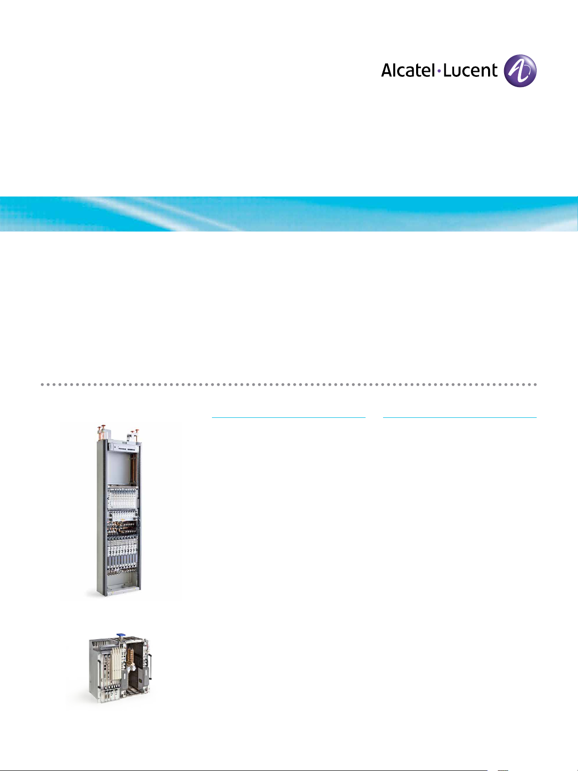
Stan dar d co nfig uration
Compac t configurat ion
Features
• Advanced radio solution for synchronous networks — in a compact
indoor structure
• ITU-R frequency plan utilization
• 128/64 QAM modulation for excellent
spectrum efficiency
• Configurable for STM-1 and STM-0
transmission capacity
• Radio link support for regenerator
station or WMSN
• Electrical/optical 155 Mb/s, 140 Mb/s
PDH, 3x34 Mb/s, 3x45 Mb/s and
63x2 Mb/s access
• Frequency reuse option available for
all supported frequency bands
• 2 Mb/s way side traffic transmitted
in RFCOH as service traffic for every
RF channel
• Network management system fully
integrated in the Alcatel-Lucent
TMN platform
• STM-1 up to 10 channels in one rack
• Packet transport thanks to Ethernet
over SDH
Benefits
• Flexible support for diverse
applications
• High-quality, reliable microwave
transmissions
• Fast and easy implementation
• Low power consumption
• Simplified maintenance with wide
band tuning
• Scalability and easy expansion that
leverages original investment
• Band cost optimization
Page 2
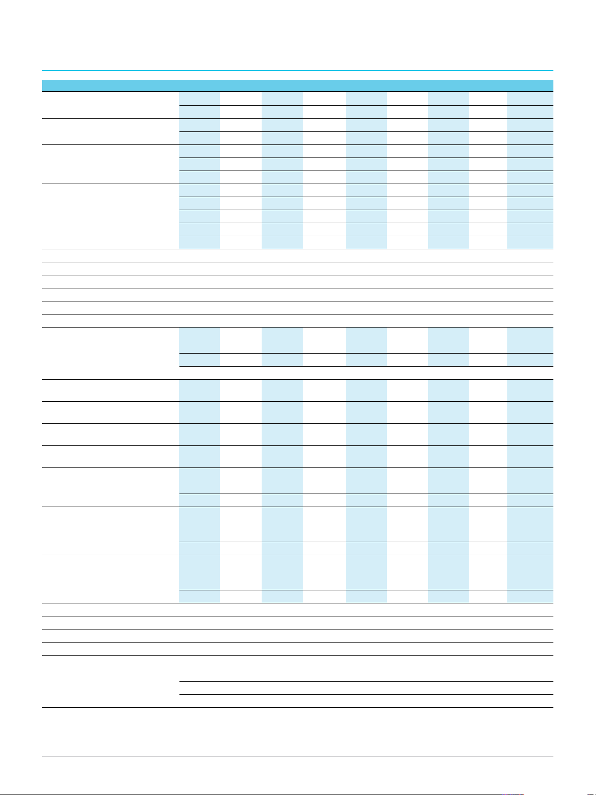
Technical specifications
RAD IO S YSTE M 964 0 LSY 9647 L SY 9662 LS Y 9667 LSY 9674 LSY 9681 LSY 9610 LSY 9611 LSY 9613 LSY
RF frequency band (GHz) 3.6- 4.2 4.4-5.0 5.9 -6.4 6.4-7.1 7.1-7.7 7.7-8.3 10.0-10.7 10.7-11.7 12.75-13.25
3.8- 4.2 7.1-7.9 8.275-8.5
RF channel F.635 F. 1099 F. 383 F.384 F. 385 F. 386 – F. 387 F. 497
Arrangements (ITU -R) F.382 F. 746
RF channel spacing (MHz)
STM-1 28/29/40 28/40 29.65 40 28 28/29.65 28 40 28
STM-0 – – – – 14 14 – 14
Transmission capacity 1 x STM-1 1 x STM-1 1 x STM-1 1 x STM-1 1 x STM-1 1 x STM-1 1 x STM-1 1 x STM-1 1 x STM-1
(per RF channel) or or or or or or or or or
2 x STM-1 2 x STM-1 2 x STM-1 2 x STM-1 2 x STM-1 2 x STM-1 2 x STM-1 2 x STM-1 2 x STM-1
or or or
1 x STM-0 1 x STM-0 1 x STM-0
Modulation 128/64 QAM
Demodulation Coherent
Adaptive equalizer 19 TAPS
Spectrum shaping Raised cosine
Coding type MLC
Frequency reuse YES
Transmit ted power (*)
ATPC (maximum) (dBm) 32 32 32 32 32 32 30 30 28
ATPC range (dB) 17 17 17 17 17 17 15 15 13
AGC dynamic range (dB) 60
Receiver threshold STM1/128 QAM
@ BER =1x10⁻³ (**) (dBm) -73 -73 -73 -73 -72.5 -72.5 -72.5 -72.5 -72
Receiver threshold STM1/128 QAM
@ BER =1x10⁻⁶ (**) (dBm) -71 -71 -71 -71 -70.5 -70.5 -70.5 -70.5 -70
Receiver threshold STM1/64 QAM
@ BER =1x10⁻³ (**) (dBm) -76.7 -76.7 – -76.5 – – – -76 –
Receiver threshold STM1/64 QAM
@ BER =1x10⁻⁶ (**) (dBm) -74.9 -74.9 – -74.7 – – – -74.2 –
Branching losses T+R (dB)
1+1 single polar (STM-1) 6.5 7.0 4.5 4 6.5 5.5 7 5.5 8
3+1 single polar (STM-1) 7.5 8.0 5.5 4.5 7.5 6.5 8 6 8.5
Net system gain (Point C-C’)
@ BER =1x10⁻³ (dB)
1+1 single polar (STM-1/128 QAM) 98.5 98.0 100.5 101 98 99 95.5 97 92
3+1 single polar (STM-1/128QAM) 97.5 97 99.5 100.5 97 98 94.5 96.5 91.5
Net system gain (Point C-C’)
@ BER =1x10⁻³ (dB)
1+1 single polar (STM-1/64 QAM) 102.2 101.7 – 104.5 – – – 100.5 –
3+1 single polar (STM-1/64QAM) 101.2 100.7 – 104.0 – – – 100.0 –
System standard (ETSI) EN 300 234 - EN 301 127 - EN 301 669 - EN 301 461 - EN 301489
Switching configuration N+0/N+1
Switching type Hitless
Station configuration Regenerator terminal – Wireless Multiser vice Node
Maximum power consumption ( W)
1+1/2+0 regenerator terminal ≤ 177
3+1/4+0 regenerator terminal ≤ 330
9+1/10+0 regenerator terminal ≤ 789
(*) Tolerance: ± 0.5 dB at ambient temp erature: ± 1.5 dB in temperature range -5°C to +55°C
(**) Guaranteed values
Note: In case of channel plans with homo polar channel space 28 MHz, the threshold value is 0.5 dB higher.
Alca tel- Lucent 96 00 LSY Lo ng-Haul D igital Rad io Links | R elease 2 | Da ta Sheet2
Page 3

Applications
• Backbone NxSTM-1 links in trunk
network in difficult environments
• Closure of STM-1 and STM-4 fiber
optic rings
• Backup for fiber optic trunk links
• Radio spurs of fiber/radio STM-N
backbones or rings
• Regional links in synchronous
networks
• Radio infrastructure for cellular
operators entering the telecommunication market
• Support of ATM/IP networks and
LAN/WAN connections
• Cost-effective replacement of
existing PDH systems
• Ethernet interfaces supporting
Synch-E
Transmission capacity
• Maximum capacity per RF channel
spacing:
¬ 2 x STM-1 (311.04 Mb/s)
¬ STM-0 (51.840 Mb/s)
• Access:
¬ 100 / 1000 Mb/s electrical
¬ STM-1 electrical/optical
¬ PDH 139.264 Mb/s
¬ 3 x 34/3 x 45 Mb/s
¬ 63 x 2 Mb/s
Physical dimensions
• Rack
¬ Height: 200 mm (compact
version) or 2200 mm (standard
version)
¬ Width: 600 mm
¬ Depth: 300 mm
• Terminal up to 9+1/10+0 in
one rack
Auxiliary channels
• Service channel
¬ Omnibus voice channel (E1)
¬ Express order wire (E2)
¬ 3 x 64 Kb/s G.703
¬ 3 x 64 Kb/s V11
¬ 1 x 9.6 Kb/s RS 232
¬ 1 x 64/128 Kb/s V11
¬ TMN channel (D1÷D3, D4÷D12)
• 2 Mb/s WST
¬ STM-1: 1 stream
¬ STM-0: not available
Power
• -48 V to -60 V DC
Network management
• F. interface RS 232 C
• QB3 interface: Ethernet AUI
• QECC interface: D1÷D3, D4÷D12
Environment
• Environmental conditions: ETSI
ETS 300 119
• Temperature: -5°C to +55°C
• EMI-EMC
• EN 301489-1
• EN 301489-4
• EN55022
www.alcatel-lucent.com A lcatel , L ucent, Alcat el-Luc ent and t he Alc atel-L ucent log o
are tradem arks o f A lcatel-Lu cent. All other trademark s are the propert y of their re spective owners .
The info rmation prese nted is subject to chang e without notic e. Alcatel-Lucent assumes no responsibility
for i naccura cies con tai ned herein. Cop yri ght © 2010 Alcatel -Lucen t. All rights rese rve d.
CPG5 677101204 (12)
 Loading...