


9400AWY REL.1.0 TECHNICAL HANDBOOK
TABLE OF CONTENTS
LIST OF FIGURES AND TABLES 6. . . . . . . . . . . . . . . . . . . . . . . . . . . . . . . . . . . . . . . . . . . . . . . . . . . . . . .
PRELIMINARY INFORMATION 11. . . . . . . . . . . . . . . . . . . . . . . . . . . . . . . . . . . . . . . . . . . . . . . . . . . . . . . . .
HANDBOOK APPLICABILITY, PURPOSE AND HISTORY 12. . . . . . . . . . . . . . . . . . . . . . . . . . . . . . . . .
HANDBOOK STRUCTURE 12. . . . . . . . . . . . . . . . . . . . . . . . . . . . . . . . . . . . . . . . . . . . . . . . . . . . . . . . . . . .
SAFETY–EMC–ESD NORMS AND EQUIPMENT LABELLING 13. . . . . . . . . . . . . . . . . . . . . . . . . . . . .
document, use and communication of its contents
All rights reserved. Passing on and copying of this
not permitted without written authorization from Alcatel.
QUICK GUIDE 14. . . . . . . . . . . . . . . . . . . . . . . . . . . . . . . . . . . . . . . . . . . . . . . . . . . . . . . . . . . . . . . . . . . . . . . .
SECTION 1: SYSTEM DESCRIPTION AND TECHNICAL SPECIFICATIONS 17. .
1–1 INTRODUCTION TO THE 9400 AWY RADIO SYSTEM FAMILY 19. . . . . . . . . . . . . . . . . . . . . . . .
1–1.1 Introduction 19. . . . . . . . . . . . . . . . . . . . . . . . . . . . . . . . . . . . . . . . . . . . . . . . . . . . . . . . . . . . . . . . .
1–1.2 General description 20. . . . . . . . . . . . . . . . . . . . . . . . . . . . . . . . . . . . . . . . . . . . . . . . . . . . . . . . . .
1–1.3 Network applications 21. . . . . . . . . . . . . . . . . . . . . . . . . . . . . . . . . . . . . . . . . . . . . . . . . . . . . . . .
1–1.3.1 Cellular backhaul applications 21. . . . . . . . . . . . . . . . . . . . . . . . . . . . . . . . . . . . . . . . . . . . . .
1–1.3.2 Fixed access networks for Public Telecom or CLECs 22. . . . . . . . . . . . . . . . . . . . . . . . . .
1–1.3.3 Private voice/data network 23. . . . . . . . . . . . . . . . . . . . . . . . . . . . . . . . . . . . . . . . . . . . . . . . .
1–1.4 User interfaces, service channels and additional interfaces 24. . . . . . . . . . . . . . . . . . . . .
1–1.4.1 User interface 24. . . . . . . . . . . . . . . . . . . . . . . . . . . . . . . . . . . . . . . . . . . . . . . . . . . . . . . . . . . .
1–1.4.2 Service channels 24. . . . . . . . . . . . . . . . . . . . . . . . . . . . . . . . . . . . . . . . . . . . . . . . . . . . . . . . .
1–1.4.3 Additional interfaces 24. . . . . . . . . . . . . . . . . . . . . . . . . . . . . . . . . . . . . . . . . . . . . . . . . . . . . . .
1–1.5 Equipment architecture 25. . . . . . . . . . . . . . . . . . . . . . . . . . . . . . . . . . . . . . . . . . . . . . . . . . . . . .
1–1.5.1 IDU (Indoor Unit) 26. . . . . . . . . . . . . . . . . . . . . . . . . . . . . . . . . . . . . . . . . . . . . . . . . . . . . . . . . .
1–1.5.2 ODU (Outdoor Unit) 29. . . . . . . . . . . . . . . . . . . . . . . . . . . . . . . . . . . . . . . . . . . . . . . . . . . . . . .
1–1.5.3 IDU–ODU cable 30. . . . . . . . . . . . . . . . . . . . . . . . . . . . . . . . . . . . . . . . . . . . . . . . . . . . . . . . . .
1–1.6 System configurations 31. . . . . . . . . . . . . . . . . . . . . . . . . . . . . . . . . . . . . . . . . . . . . . . . . . . . . . .
1–1.6.1 Unprotected configurations 32. . . . . . . . . . . . . . . . . . . . . . . . . . . . . . . . . . . . . . . . . . . . . . . . .
1–1.6.2 Protected configurations 34. . . . . . . . . . . . . . . . . . . . . . . . . . . . . . . . . . . . . . . . . . . . . . . . . . .
1–2 TECHNICAL SPECIFICATIONS 39. . . . . . . . . . . . . . . . . . . . . . . . . . . . . . . . . . . . . . . . . . . . . . . . . . . .
1–2.1 General Characteristics 40. . . . . . . . . . . . . . . . . . . . . . . . . . . . . . . . . . . . . . . . . . . . . . . . . . . . . .
1–2.1.1 Reference system standards 41. . . . . . . . . . . . . . . . . . . . . . . . . . . . . . . . . . . . . . . . . . . . . . .
05011203 S404102602
02 040924 S404092102
01 040510
ED DATE CHANGE NOTE APPRAISAL AUTHORITY ORIGINATOR
ED
03
1AA 00014 0004 (9007) A4 – ALICE 04.10
B.HURINVILLE E.CORRADINI ITAVE
BESTETTI,CREMONESI
P.CREMONESI ITAVE E.CORRADINI ITAVE
A.BESTETTI
P.CREMONESI ITAVE E.CORRADINI ITAVE
M.FERRARIO G.ZILIANI, F.FASS
9400AWY Rel.1.0
UP TO V1.0.2
TECHNICAL HANDBOOK
268
1
268
/3DB 05653 BA AA

1–2.1.2 RF channelling 42. . . . . . . . . . . . . . . . . . . . . . . . . . . . . . . . . . . . . . . . . . . . . . . . . . . . . . . . . . .
1–2.1.3 Transmitted power at antenna port (ETSI and FCC) 43. . . . . . . . . . . . . . . . . . . . . . . . . . .
1–2.1.4 99% power channel bandwidth and Emission Designator 44. . . . . . . . . . . . . . . . . . . . . . .
1–2.1.5 ETSI System Characteristics 45. . . . . . . . . . . . . . . . . . . . . . . . . . . . . . . . . . . . . . . . . . . . . . .
1–2.1.6 FCC System Characteristics 49. . . . . . . . . . . . . . . . . . . . . . . . . . . . . . . . . . . . . . . . . . . . . . . .
1–2.1.7 Antenna gain (typical/guaranteed gain at mid–band) 53. . . . . . . . . . . . . . . . . . . . . . . . . . .
1–2.1.8 Switching system 53. . . . . . . . . . . . . . . . . . . . . . . . . . . . . . . . . . . . . . . . . . . . . . . . . . . . . . . . .
1–2.2 Tributary interfaces 54. . . . . . . . . . . . . . . . . . . . . . . . . . . . . . . . . . . . . . . . . . . . . . . . . . . . . . . . . .
1–2.3 Modem 54. . . . . . . . . . . . . . . . . . . . . . . . . . . . . . . . . . . . . . . . . . . . . . . . . . . . . . . . . . . . . . . . . . . . . .
1–2.4 Maximum capacity and Modulation type 54. . . . . . . . . . . . . . . . . . . . . . . . . . . . . . . . . . . . . . .
1–2.5 IDU–ODU cable 54. . . . . . . . . . . . . . . . . . . . . . . . . . . . . . . . . . . . . . . . . . . . . . . . . . . . . . . . . . . . . .
1–2.6 Man–machine interface 55. . . . . . . . . . . . . . . . . . . . . . . . . . . . . . . . . . . . . . . . . . . . . . . . . . . . . .
1–2.7 Alarms 55. . . . . . . . . . . . . . . . . . . . . . . . . . . . . . . . . . . . . . . . . . . . . . . . . . . . . . . . . . . . . . . . . . . . . .
1–2.8 Power supply 55. . . . . . . . . . . . . . . . . . . . . . . . . . . . . . . . . . . . . . . . . . . . . . . . . . . . . . . . . . . . . . . .
1–2.9 Mechanical characteristics 55. . . . . . . . . . . . . . . . . . . . . . . . . . . . . . . . . . . . . . . . . . . . . . . . . . .
1–2.10 Environmental conditions 56. . . . . . . . . . . . . . . . . . . . . . . . . . . . . . . . . . . . . . . . . . . . . . . . . . .
1–2.11 Electro–magnetic compatibility/safety 56. . . . . . . . . . . . . . . . . . . . . . . . . . . . . . . . . . . . . . . .
SECTION 2: SYSTEM COMPOSITION AND CONFIGURATIONS 57. . . . . . . . . . . .
2–1 IDU PART LIST 59. . . . . . . . . . . . . . . . . . . . . . . . . . . . . . . . . . . . . . . . . . . . . . . . . . . . . . . . . . . . . . . . . .
2–2 IDU PROVISIONING 63. . . . . . . . . . . . . . . . . . . . . . . . . . . . . . . . . . . . . . . . . . . . . . . . . . . . . . . . . . . . . .
2–2.1 1+0 Compact IDU composition and equipment provisioning 64. . . . . . . . . . . . . . . . . . . .
2–2.2 1+0 Extendable IDU composition and equipment provisioning 67. . . . . . . . . . . . . . . . . .
2–2.3 1+1 IDU composition and equipment provisioning 70. . . . . . . . . . . . . . . . . . . . . . . . . . . . .
document, use and communication of its contents
All rights reserved. Passing on and copying of this
not permitted without written authorization from Alcatel.
2–3 ODU AND ANTENNA CONFIGURATIONS, PART LISTS AND PROVISIONING 73. . . . . . . . .
2–3.1 ODU general description 73. . . . . . . . . . . . . . . . . . . . . . . . . . . . . . . . . . . . . . . . . . . . . . . . . . . . .
2–3.2 ODU mechanical design 73. . . . . . . . . . . . . . . . . . . . . . . . . . . . . . . . . . . . . . . . . . . . . . . . . . . . . .
2–3.3 ODU configurations 74. . . . . . . . . . . . . . . . . . . . . . . . . . . . . . . . . . . . . . . . . . . . . . . . . . . . . . . . . .
2–3.4 ODU part lists 75. . . . . . . . . . . . . . . . . . . . . . . . . . . . . . . . . . . . . . . . . . . . . . . . . . . . . . . . . . . . . . .
2–3.5 Antenna configurations 80. . . . . . . . . . . . . . . . . . . . . . . . . . . . . . . . . . . . . . . . . . . . . . . . . . . . . .
2–3.5.1 1+0 configuration with integrated antenna 81. . . . . . . . . . . . . . . . . . . . . . . . . . . . . . . . . . . .
2–3.5.2 1+1 HSB configuration 82. . . . . . . . . . . . . . . . . . . . . . . . . . . . . . . . . . . . . . . . . . . . . . . . . . . . .
2–3.5.3 Configuration with separated antenna 83. . . . . . . . . . . . . . . . . . . . . . . . . . . . . . . . . . . . . . .
2–3.6 Integrated antenna part list 85. . . . . . . . . . . . . . . . . . . . . . . . . . . . . . . . . . . . . . . . . . . . . . . . . . .
2–3.7 Coupler part list 86. . . . . . . . . . . . . . . . . . . . . . . . . . . . . . . . . . . . . . . . . . . . . . . . . . . . . . . . . . . . .
2–3.8 Part list of ODU accessories and installation materials 87. . . . . . . . . . . . . . . . . . . . . . . . .
2–4 IDU OPERATIVE INFORMATION 89. . . . . . . . . . . . . . . . . . . . . . . . . . . . . . . . . . . . . . . . . . . . . . . . . . .
2–4.1 Cautions to avoid equipment damage 90. . . . . . . . . . . . . . . . . . . . . . . . . . . . . . . . . . . . . . . . .
2–4.2 Access unit 92. . . . . . . . . . . . . . . . . . . . . . . . . . . . . . . . . . . . . . . . . . . . . . . . . . . . . . . . . . . . . . . . .
2–4.2.1 Access unit front view and access points 93. . . . . . . . . . . . . . . . . . . . . . . . . . . . . . . . . . . . .
2–4.2.2 Summary of Access unit external interfaces 93. . . . . . . . . . . . . . . . . . . . . . . . . . . . . . . . . .
2–4.3 Main IDU unit 103. . . . . . . . . . . . . . . . . . . . . . . . . . . . . . . . . . . . . . . . . . . . . . . . . . . . . . . . . . . . . . . .
2–4.3.1 Main IDU unit assembly 103. . . . . . . . . . . . . . . . . . . . . . . . . . . . . . . . . . . . . . . . . . . . . . . . . . . .
2–4.3.2 Main IDU unit front view and access points 104. . . . . . . . . . . . . . . . . . . . . . . . . . . . . . . . . . .
2–4.4 Flash Card 109. . . . . . . . . . . . . . . . . . . . . . . . . . . . . . . . . . . . . . . . . . . . . . . . . . . . . . . . . . . . . . . . . .
2–4.4.1 General 109. . . . . . . . . . . . . . . . . . . . . . . . . . . . . . . . . . . . . . . . . . . . . . . . . . . . . . . . . . . . . . . . . .
2–4.4.2 Flash Card identification 109. . . . . . . . . . . . . . . . . . . . . . . . . . . . . . . . . . . . . . . . . . . . . . . . . . .
2–4.4.3 Flash Card contents 110. . . . . . . . . . . . . . . . . . . . . . . . . . . . . . . . . . . . . . . . . . . . . . . . . . . . . . .
2–4.4.4 Flash Card upgrade 111. . . . . . . . . . . . . . . . . . . . . . . . . . . . . . . . . . . . . . . . . . . . . . . . . . . . . . .
2–4.5 Extension IDU unit 112. . . . . . . . . . . . . . . . . . . . . . . . . . . . . . . . . . . . . . . . . . . . . . . . . . . . . . . . . . .
2–4.5.1 Extension IDU unit assembly 112. . . . . . . . . . . . . . . . . . . . . . . . . . . . . . . . . . . . . . . . . . . . . . .
1AA 00014 0004 (9007) A4 – ALICE 04.10
ED
03
268
/3DB 05653 BA AA
2
268

2–4.5.2 Extension IDU unit front view and access points 113. . . . . . . . . . . . . . . . . . . . . . . . . . . . . .
2–4.6 Fans unit 115. . . . . . . . . . . . . . . . . . . . . . . . . . . . . . . . . . . . . . . . . . . . . . . . . . . . . . . . . . . . . . . . . . . .
2–5 DISTRIBUTOR SUBRACKS 117. . . . . . . . . . . . . . . . . . . . . . . . . . . . . . . . . . . . . . . . . . . . . . . . . . . . . . .
2–6 ODU AND RELATED OPTIONAL TOOLS OPERATIVE INFORMATION 119. . . . . . . . . . . . . . . . .
2–6.1 ODU operative information 119. . . . . . . . . . . . . . . . . . . . . . . . . . . . . . . . . . . . . . . . . . . . . . . . . . .
2–6.2 PSK operative information 121. . . . . . . . . . . . . . . . . . . . . . . . . . . . . . . . . . . . . . . . . . . . . . . . . . .
2–6.2.1 PSK assembly description 121. . . . . . . . . . . . . . . . . . . . . . . . . . . . . . . . . . . . . . . . . . . . . . . . .
2–6.2.2 PSK handset description 122. . . . . . . . . . . . . . . . . . . . . . . . . . . . . . . . . . . . . . . . . . . . . . . . . . .
2–6.2.3 PSK instructions for tests/measurements 123. . . . . . . . . . . . . . . . . . . . . . . . . . . . . . . . . . . .
2–6.3 Rx power monitoring cable operative information 124. . . . . . . . . . . . . . . . . . . . . . . . . . . . . .
2–7 STATION LAYOUTS 125. . . . . . . . . . . . . . . . . . . . . . . . . . . . . . . . . . . . . . . . . . . . . . . . . . . . . . . . . . . . . .
2–7.1 Constraints for 9400AWY–IDU multiple equipping in a rack 126. . . . . . . . . . . . . . . . . . . . .
2–7.2 Hardware setting 126. . . . . . . . . . . . . . . . . . . . . . . . . . . . . . . . . . . . . . . . . . . . . . . . . . . . . . . . . . . .
2–7.3 Hardware installation 126. . . . . . . . . . . . . . . . . . . . . . . . . . . . . . . . . . . . . . . . . . . . . . . . . . . . . . . .
document, use and communication of its contents
All rights reserved. Passing on and copying of this
not permitted without written authorization from Alcatel.
2–7.4 Layouts and connections 127. . . . . . . . . . . . . . . . . . . . . . . . . . . . . . . . . . . . . . . . . . . . . . . . . . . .
2–7.4.1 9400AWY (1+0) compact 127. . . . . . . . . . . . . . . . . . . . . . . . . . . . . . . . . . . . . . . . . . . . . . . . . .
2–7.4.2 9400AWY (1+0) Extendable to (1+1) 128. . . . . . . . . . . . . . . . . . . . . . . . . . . . . . . . . . . . . . . .
2–7.4.3 9400AWY (1+1) HSB–SD or FD–DA AP/CP with two antennas 129. . . . . . . . . . . . . . . . .
2–7.4.4 9400AWY (1+1) HSB or FD–CP with one antenna 130. . . . . . . . . . . . . . . . . . . . . . . . . . . . .
2–7.4.5 9400AWY (1+1) FD–AP with one double polar external antenna 131. . . . . . . . . . . . . . . .
SECTION 3: MAINTENANCE 133. . . . . . . . . . . . . . . . . . . . . . . . . . . . . . . . . . . . . . . . . . .
3–1 MAINTENANCE POLICY 135. . . . . . . . . . . . . . . . . . . . . . . . . . . . . . . . . . . . . . . . . . . . . . . . . . . . . . . . . .
3–1.1 Classification of maintenance levels and operators 135. . . . . . . . . . . . . . . . . . . . . . . . . . . .
3–1.2 First Level Maintenance Personnel skill 136. . . . . . . . . . . . . . . . . . . . . . . . . . . . . . . . . . . . . . .
3–1.3 Second Level Maintenance Personnel skill 136. . . . . . . . . . . . . . . . . . . . . . . . . . . . . . . . . . . .
3–2 USE OF EOW FUNCTIONS 137. . . . . . . . . . . . . . . . . . . . . . . . . . . . . . . . . . . . . . . . . . . . . . . . . . . . . . . .
3–2.1 Telephone kit and telephone set description 138. . . . . . . . . . . . . . . . . . . . . . . . . . . . . . . . . . .
3–2.2 Setting information 140. . . . . . . . . . . . . . . . . . . . . . . . . . . . . . . . . . . . . . . . . . . . . . . . . . . . . . . . . .
3–2.3 Call Set–up/End by Telephone Set connected on the Access unit 143. . . . . . . . . . . . . . .
3–2.4 Call Set–up/End by the PSK connected to the ODU 143. . . . . . . . . . . . . . . . . . . . . . . . . . . . .
3–3 MAINTENANCE TOOLS AND SPARE PARTS 145. . . . . . . . . . . . . . . . . . . . . . . . . . . . . . . . . . . . . . .
3–3.1 Introduction 145. . . . . . . . . . . . . . . . . . . . . . . . . . . . . . . . . . . . . . . . . . . . . . . . . . . . . . . . . . . . . . . . .
3–3.2 Instruments and accessories 145. . . . . . . . . . . . . . . . . . . . . . . . . . . . . . . . . . . . . . . . . . . . . . . . .
3–3.2.1 Software tools 145. . . . . . . . . . . . . . . . . . . . . . . . . . . . . . . . . . . . . . . . . . . . . . . . . . . . . . . . . . . .
3–3.2.2 Maintenance Tool Kit 145. . . . . . . . . . . . . . . . . . . . . . . . . . . . . . . . . . . . . . . . . . . . . . . . . . . . . .
3–3.3 Set of spare parts 148. . . . . . . . . . . . . . . . . . . . . . . . . . . . . . . . . . . . . . . . . . . . . . . . . . . . . . . . . . . .
3–3.3.1 Types of Spare Parts 148. . . . . . . . . . . . . . . . . . . . . . . . . . . . . . . . . . . . . . . . . . . . . . . . . . . . . .
3–3.3.2 Number of spare parts 149. . . . . . . . . . . . . . . . . . . . . . . . . . . . . . . . . . . . . . . . . . . . . . . . . . . . .
3–3.3.3 General rules on spare parts management 149. . . . . . . . . . . . . . . . . . . . . . . . . . . . . . . . . . .
3–3.3.4 Spare Flash Card management 149. . . . . . . . . . . . . . . . . . . . . . . . . . . . . . . . . . . . . . . . . . . . .
1AA 00014 0004 (9007) A4 – ALICE 04.10
3–4 FIRST LEVEL MAINTENANCE 151. . . . . . . . . . . . . . . . . . . . . . . . . . . . . . . . . . . . . . . . . . . . . . . . . . . .
3–4.1 Introduction 151. . . . . . . . . . . . . . . . . . . . . . . . . . . . . . . . . . . . . . . . . . . . . . . . . . . . . . . . . . . . . . . . .
3–4.2 System state display by visual indications 151. . . . . . . . . . . . . . . . . . . . . . . . . . . . . . . . . . . .
3–4.2.1 LED test 151. . . . . . . . . . . . . . . . . . . . . . . . . . . . . . . . . . . . . . . . . . . . . . . . . . . . . . . . . . . . . . . . .
3–4.2.2 Alarm LEDs on the MAIN unit 151. . . . . . . . . . . . . . . . . . . . . . . . . . . . . . . . . . . . . . . . . . . . . . .
3–4.2.3 Alarm LEDs on the Extension unit 153. . . . . . . . . . . . . . . . . . . . . . . . . . . . . . . . . . . . . . . . . . .
3–4.3 Craft Terminal interface commonly used commands 154. . . . . . . . . . . . . . . . . . . . . . . . . . .
ED
03
268
3
268
/3DB 05653 BA AA

3–5 SECOND LEVEL MAINTENANCE 155. . . . . . . . . . . . . . . . . . . . . . . . . . . . . . . . . . . . . . . . . . . . . . . . . .
3–5.1 Introduction 155. . . . . . . . . . . . . . . . . . . . . . . . . . . . . . . . . . . . . . . . . . . . . . . . . . . . . . . . . . . . . . . . .
3–5.2 Warnings 156. . . . . . . . . . . . . . . . . . . . . . . . . . . . . . . . . . . . . . . . . . . . . . . . . . . . . . . . . . . . . . . . . . . .
3–5.2.1 EMC norms 156. . . . . . . . . . . . . . . . . . . . . . . . . . . . . . . . . . . . . . . . . . . . . . . . . . . . . . . . . . . . . .
3–5.2.2 Safety rules 156. . . . . . . . . . . . . . . . . . . . . . . . . . . . . . . . . . . . . . . . . . . . . . . . . . . . . . . . . . . . . .
3–5.2.3 Cautions to avoid equipment damage 156. . . . . . . . . . . . . . . . . . . . . . . . . . . . . . . . . . . . . . .
3–5.3 Routine (preventive) Maintenance 157. . . . . . . . . . . . . . . . . . . . . . . . . . . . . . . . . . . . . . . . . . . .
3–5.3.1 Routine (preventive) Maintenance every year 157. . . . . . . . . . . . . . . . . . . . . . . . . . . . . . . . .
3–5.3.2 Routine (preventive) Maintenance for Fans unit 158. . . . . . . . . . . . . . . . . . . . . . . . . . . . . . .
3–5.4 Consequences of unit extraction in the IDU 159. . . . . . . . . . . . . . . . . . . . . . . . . . . . . . . . . . . .
3–5.4.1 Consequences of the MAIN unit extraction 159. . . . . . . . . . . . . . . . . . . . . . . . . . . . . . . . . . .
3–5.4.2 Consequences of the Extension unit extraction 160. . . . . . . . . . . . . . . . . . . . . . . . . . . . . . .
3–5.4.3 Consequences of the Access unit extraction 160. . . . . . . . . . . . . . . . . . . . . . . . . . . . . . . . . .
3–5.4.4 Consequences of the FANS unit extraction 160. . . . . . . . . . . . . . . . . . . . . . . . . . . . . . . . . . .
3–5.4.5 Note on dummy plate 160. . . . . . . . . . . . . . . . . . . . . . . . . . . . . . . . . . . . . . . . . . . . . . . . . . . . . .
3–5.5 Corrective Maintenance 161. . . . . . . . . . . . . . . . . . . . . . . . . . . . . . . . . . . . . . . . . . . . . . . . . . . . . .
3–5.5.1 General flow–chart 161. . . . . . . . . . . . . . . . . . . . . . . . . . . . . . . . . . . . . . . . . . . . . . . . . . . . . . . .
3–5.5.2 Alarm acknowledgment and attending 162. . . . . . . . . . . . . . . . . . . . . . . . . . . . . . . . . . . . . . .
3–5.5.3 Troubleshooting starting with visual indications 163. . . . . . . . . . . . . . . . . . . . . . . . . . . . . . .
3–5.5.4 Troubleshooting via Craft Terminal 165. . . . . . . . . . . . . . . . . . . . . . . . . . . . . . . . . . . . . . . . . .
3–5.5.5 IDU unit replacement 167. . . . . . . . . . . . . . . . . . . . . . . . . . . . . . . . . . . . . . . . . . . . . . . . . . . . . .
3–5.5.6 ODU replacement 176. . . . . . . . . . . . . . . . . . . . . . . . . . . . . . . . . . . . . . . . . . . . . . . . . . . . . . . . .
3–5.6 Faulty unit repair and Repair Form 176. . . . . . . . . . . . . . . . . . . . . . . . . . . . . . . . . . . . . . . . . . . .
3–5.6.1 Faulty unit sending back to repair center 176. . . . . . . . . . . . . . . . . . . . . . . . . . . . . . . . . . . . .
3–5.6.2 Repair Form filling 176. . . . . . . . . . . . . . . . . . . . . . . . . . . . . . . . . . . . . . . . . . . . . . . . . . . . . . . .
document, use and communication of its contents
All rights reserved. Passing on and copying of this
not permitted without written authorization from Alcatel.
SECTION 4: FUNCTIONAL DESCRIPTION 179. . . . . . . . . . . . . . . . . . . . . . . . . . . . . . .
4–1 SYSTEM DESCRIPTION 181. . . . . . . . . . . . . . . . . . . . . . . . . . . . . . . . . . . . . . . . . . . . . . . . . . . . . . . . . .
4–1.1 Functional description and components 182. . . . . . . . . . . . . . . . . . . . . . . . . . . . . . . . . . . . . .
4–1.1.1 Functions and configurations 182. . . . . . . . . . . . . . . . . . . . . . . . . . . . . . . . . . . . . . . . . . . . . . .
4–1.1.2 IDU and ODU Components 183. . . . . . . . . . . . . . . . . . . . . . . . . . . . . . . . . . . . . . . . . . . . . . . .
4–1.2 Control subsystem hardware architecture 187. . . . . . . . . . . . . . . . . . . . . . . . . . . . . . . . . . . . .
4–1.2.1 Function partitioning 187. . . . . . . . . . . . . . . . . . . . . . . . . . . . . . . . . . . . . . . . . . . . . . . . . . . . . . .
4–1.2.2 Control elements 187. . . . . . . . . . . . . . . . . . . . . . . . . . . . . . . . . . . . . . . . . . . . . . . . . . . . . . . . . .
4–1.3 IDU functional description 189. . . . . . . . . . . . . . . . . . . . . . . . . . . . . . . . . . . . . . . . . . . . . . . . . . . .
4–1.3.1 1+0 Compact IDU configuration 190. . . . . . . . . . . . . . . . . . . . . . . . . . . . . . . . . . . . . . . . . . . . .
4–1.3.2 1+0 IDU Extendable configuration 191. . . . . . . . . . . . . . . . . . . . . . . . . . . . . . . . . . . . . . . . . . .
4–1.3.3 1+1 IDU configuration 192. . . . . . . . . . . . . . . . . . . . . . . . . . . . . . . . . . . . . . . . . . . . . . . . . . . . .
4–1.3.4 Access IDU unit 193. . . . . . . . . . . . . . . . . . . . . . . . . . . . . . . . . . . . . . . . . . . . . . . . . . . . . . . . . .
4–1.3.5 Main IDU unit 193. . . . . . . . . . . . . . . . . . . . . . . . . . . . . . . . . . . . . . . . . . . . . . . . . . . . . . . . . . . . .
4–1.3.6 Extension IDU unit 196. . . . . . . . . . . . . . . . . . . . . . . . . . . . . . . . . . . . . . . . . . . . . . . . . . . . . . . .
4–1.4 ODU functional description 197. . . . . . . . . . . . . . . . . . . . . . . . . . . . . . . . . . . . . . . . . . . . . . . . . . .
4–1.5 Radio Transmission features 199. . . . . . . . . . . . . . . . . . . . . . . . . . . . . . . . . . . . . . . . . . . . . . . . .
4–1.5.1 Frequency Agility 199. . . . . . . . . . . . . . . . . . . . . . . . . . . . . . . . . . . . . . . . . . . . . . . . . . . . . . . . .
4–1.5.2 Transmitted power control: ATPC function 199. . . . . . . . . . . . . . . . . . . . . . . . . . . . . . . . . . . .
4–1.5.3 Transmitted power control: RTPC function 202. . . . . . . . . . . . . . . . . . . . . . . . . . . . . . . . . . .
4–1.5.4 Internal service channel 203. . . . . . . . . . . . . . . . . . . . . . . . . . . . . . . . . . . . . . . . . . . . . . . . . . . .
4–1.5.5 User service channels 204. . . . . . . . . . . . . . . . . . . . . . . . . . . . . . . . . . . . . . . . . . . . . . . . . . . . .
4–1.6 Protection schemes 207. . . . . . . . . . . . . . . . . . . . . . . . . . . . . . . . . . . . . . . . . . . . . . . . . . . . . . . . . .
4–1.6.1 Tx protection schemes 207. . . . . . . . . . . . . . . . . . . . . . . . . . . . . . . . . . . . . . . . . . . . . . . . . . . . .
4–1.6.2 Rx protection schemes 209. . . . . . . . . . . . . . . . . . . . . . . . . . . . . . . . . . . . . . . . . . . . . . . . . . . .
4–1.6.3 User service channel protection 210. . . . . . . . . . . . . . . . . . . . . . . . . . . . . . . . . . . . . . . . . . . . .
1AA 00014 0004 (9007) A4 – ALICE 04.10
ED
03
268
/3DB 05653 BA AA
4
268

4–1.7 Loopbacks 211. . . . . . . . . . . . . . . . . . . . . . . . . . . . . . . . . . . . . . . . . . . . . . . . . . . . . . . . . . . . . . . . . .
4–1.7.1 IDU loopbacks 211. . . . . . . . . . . . . . . . . . . . . . . . . . . . . . . . . . . . . . . . . . . . . . . . . . . . . . . . . . . .
4–1.7.2 IDU loopbacks 212. . . . . . . . . . . . . . . . . . . . . . . . . . . . . . . . . . . . . . . . . . . . . . . . . . . . . . . . . . . .
4–1.8 Network management and interworking 214. . . . . . . . . . . . . . . . . . . . . . . . . . . . . . . . . . . . . . .
4–1.8.1 Local monitoring 214. . . . . . . . . . . . . . . . . . . . . . . . . . . . . . . . . . . . . . . . . . . . . . . . . . . . . . . . . .
4–1.8.2 Small/medium sized networks: RECT 215. . . . . . . . . . . . . . . . . . . . . . . . . . . . . . . . . . . . . . . .
4–1.8.3 Large mixed network: TMN 215. . . . . . . . . . . . . . . . . . . . . . . . . . . . . . . . . . . . . . . . . . . . . . . . .
4–1.8.4 1353 SH operation system 216. . . . . . . . . . . . . . . . . . . . . . . . . . . . . . . . . . . . . . . . . . . . . . . . .
4–1.8.5 Use of NMS channels 217. . . . . . . . . . . . . . . . . . . . . . . . . . . . . . . . . . . . . . . . . . . . . . . . . . . . .
4–2 ALARMS 221. . . . . . . . . . . . . . . . . . . . . . . . . . . . . . . . . . . . . . . . . . . . . . . . . . . . . . . . . . . . . . . . . . . . . . . .
4–2.1 Alarms Provided by Item HW 221. . . . . . . . . . . . . . . . . . . . . . . . . . . . . . . . . . . . . . . . . . . . . . . . .
4–2.1.1 IDU Alarms 222. . . . . . . . . . . . . . . . . . . . . . . . . . . . . . . . . . . . . . . . . . . . . . . . . . . . . . . . . . . . . .
4–2.1.2 ODU Alarms 224. . . . . . . . . . . . . . . . . . . . . . . . . . . . . . . . . . . . . . . . . . . . . . . . . . . . . . . . . . . . .
4–2.2 Alarm severity 225. . . . . . . . . . . . . . . . . . . . . . . . . . . . . . . . . . . . . . . . . . . . . . . . . . . . . . . . . . . . . . .
4–2.2.1 Communication Alarms 226. . . . . . . . . . . . . . . . . . . . . . . . . . . . . . . . . . . . . . . . . . . . . . . . . . . .
4–2.2.2 Equipment Alarms 227. . . . . . . . . . . . . . . . . . . . . . . . . . . . . . . . . . . . . . . . . . . . . . . . . . . . . . . .
document, use and communication of its contents
All rights reserved. Passing on and copying of this
not permitted without written authorization from Alcatel.
SECTION 5: APPENDICES 229. . . . . . . . . . . . . . . . . . . . . . . . . . . . . . . . . . . . . . . . . . . . .
APPENDIX A : SAFETY–EMC–ESD NORMS AND EQUIPMENT LABELLING 231. . . . . . . . . . . . . . .
A.1 : Introduction 231. . . . . . . . . . . . . . . . . . . . . . . . . . . . . . . . . . . . . . . . . . . . . . . . . . . . . . . . . . . . . . . . . .
A.2 : Compliance with European Norms 231. . . . . . . . . . . . . . . . . . . . . . . . . . . . . . . . . . . . . . . . . . . . .
A.3 : Safety Rules 232. . . . . . . . . . . . . . . . . . . . . . . . . . . . . . . . . . . . . . . . . . . . . . . . . . . . . . . . . . . . . . . . . .
A.3.1 : General Rules 232. . . . . . . . . . . . . . . . . . . . . . . . . . . . . . . . . . . . . . . . . . . . . . . . . . . . . . . . . . . . .
A.3.2 : Labels Indicating Danger, Forbiddance, Command 233. . . . . . . . . . . . . . . . . . . . . . . . . . . . .
A.3.3 : Dangerous Electrical Voltages 234. . . . . . . . . . . . . . . . . . . . . . . . . . . . . . . . . . . . . . . . . . . . . . .
A.3.4 : Risks of Explosions 235. . . . . . . . . . . . . . . . . . . . . . . . . . . . . . . . . . . . . . . . . . . . . . . . . . . . . . . . .
A.3.5 : Moving Mechanical Parts 235. . . . . . . . . . . . . . . . . . . . . . . . . . . . . . . . . . . . . . . . . . . . . . . . . . . .
A.3.6 : Heat–radiating Mechanical Parts 236. . . . . . . . . . . . . . . . . . . . . . . . . . . . . . . . . . . . . . . . . . . . .
A.3.7 : Microwave radiations 237. . . . . . . . . . . . . . . . . . . . . . . . . . . . . . . . . . . . . . . . . . . . . . . . . . . . . . .
A.3.8 : Specific safety rules in this handbook 237. . . . . . . . . . . . . . . . . . . . . . . . . . . . . . . . . . . . . . . . .
A.4 : Electromagnetic Compatibility (EMC norms) 238. . . . . . . . . . . . . . . . . . . . . . . . . . . . . . . . . . . .
A.4.1 : EMC General Norms – Installation 238. . . . . . . . . . . . . . . . . . . . . . . . . . . . . . . . . . . . . . . . . . . .
A.4.2 : EMC General Norms – Turn–on, Tests & Operation 238. . . . . . . . . . . . . . . . . . . . . . . . . . . . .
A.4.3 : EMC General Norms – Maintenance 238. . . . . . . . . . . . . . . . . . . . . . . . . . . . . . . . . . . . . . . . . .
A.5 : Equipment protection against electrostatic discharges 239. . . . . . . . . . . . . . . . . . . . . . . . . .
A.6 : Suggestions, notes and cautions 239. . . . . . . . . . . . . . . . . . . . . . . . . . . . . . . . . . . . . . . . . . . . . .
A.7 : Labels affixed to the Equipment 240. . . . . . . . . . . . . . . . . . . . . . . . . . . . . . . . . . . . . . . . . . . . . . . .
A.7.1 : Labels specific for the equipment 240. . . . . . . . . . . . . . . . . . . . . . . . . . . . . . . . . . . . . . . . . . . . .
A.7.2 : General Use Labels 242. . . . . . . . . . . . . . . . . . . . . . . . . . . . . . . . . . . . . . . . . . . . . . . . . . . . . . . .
1AA 00014 0004 (9007) A4 – ALICE 04.10
APPENDIX B : DOCUMENTATION GUIDE 247. . . . . . . . . . . . . . . . . . . . . . . . . . . . . . . . . . . . . . . . . . . . . . .
B.1 : Handbook guide 247. . . . . . . . . . . . . . . . . . . . . . . . . . . . . . . . . . . . . . . . . . . . . . . . . . . . . . . . . . . . . .
B.1.1 : Handbook applicability 247. . . . . . . . . . . . . . . . . . . . . . . . . . . . . . . . . . . . . . . . . . . . . . . . . . . . . .
B.1.2 : Purpose of the handbook 248. . . . . . . . . . . . . . . . . . . . . . . . . . . . . . . . . . . . . . . . . . . . . . . . . . . .
B.1.3 : Handbook history 249. . . . . . . . . . . . . . . . . . . . . . . . . . . . . . . . . . . . . . . . . . . . . . . . . . . . . . . . . . .
B.2 : Documentation set description 251. . . . . . . . . . . . . . . . . . . . . . . . . . . . . . . . . . . . . . . . . . . . . . . .
B.2.1 : 9400AWY Rel.1.0 product–release–version handbooks 251. . . . . . . . . . . . . . . . . . . . . . . . .
B.2.2 : General on Alcatel Customer Documentation 254. . . . . . . . . . . . . . . . . . . . . . . . . . . . . . . . . .
APPENDIX C : LIST OF SYMBOLS AND ABBREVIATIONS 259. . . . . . . . . . . . . . . . . . . . . . . . . . . . . . .
ED
03
268
5
268
/3DB 05653 BA AA

LIST OF FIGURES AND TABLES
FIGURES
Fig. 1. Cellular GSM applications 21. . . . . . . . . . . . . . . . . . . . . . . . . . . . . . . . . . . . . . . . . . . . . . . . . . . . . . . .
Fig. 2. Cellular UMTS applications 21. . . . . . . . . . . . . . . . . . . . . . . . . . . . . . . . . . . . . . . . . . . . . . . . . . . . . . .
Fig. 3. Wireless Access for large customers by Public Telecom 22. . . . . . . . . . . . . . . . . . . . . . . . . . . . . .
Fig. 4. Alcatel 9400 AWY integration in Wireless IP and LMDS network 23. . . . . . . . . . . . . . . . . . . . . . .
Fig. 5. Alcatel 9400 AWY integration in Wireless IP and LMDS network 23. . . . . . . . . . . . . . . . . . . . . . .
Fig. 6. “1+0” and “1+1” IDU shelves 26. . . . . . . . . . . . . . . . . . . . . . . . . . . . . . . . . . . . . . . . . . . . . . . . . . . . . .
Fig. 7. ODU block diagram 30. . . . . . . . . . . . . . . . . . . . . . . . . . . . . . . . . . . . . . . . . . . . . . . . . . . . . . . . . . . . .
Fig. 8. Equipment and block diagrams of 9400AWY 1+0 COMPACT 32. . . . . . . . . . . . . . . . . . . . . . . . .
Fig. 9. Equipment and block diagrams of 9400AWY 1+0 EXTENDABLE 33. . . . . . . . . . . . . . . . . . . . . .
Fig. 10. Equipment and block diagrams of 9400AWY 1+1 HSB SD 34. . . . . . . . . . . . . . . . . . . . . . . . . . .
Fig. 11. Equipment and block diagrams of 9400AWY 1+1 HSB (one antenna) 35. . . . . . . . . . . . . . . . .
Fig. 12. Equipment and block diagrams of 9400AWY 1+1 FD Double Antenna CP or AP 36. . . . . . . .
Fig. 13. Equipment and block diagrams of 9400AWY 1+1 FD one antenna CP 37. . . . . . . . . . . . . . . .
Fig. 14. Equipment and block diagrams of 9400AWY 1+1 FD one antenna AP 38. . . . . . . . . . . . . . . .
Fig. 15. 1+0 Compact IDU: composition 64. . . . . . . . . . . . . . . . . . . . . . . . . . . . . . . . . . . . . . . . . . . . . . . . . .
Fig. 16. 1+0 Extendable IDU: composition 67. . . . . . . . . . . . . . . . . . . . . . . . . . . . . . . . . . . . . . . . . . . . . . . .
Fig. 17. 1+1 IDU: composition 70. . . . . . . . . . . . . . . . . . . . . . . . . . . . . . . . . . . . . . . . . . . . . . . . . . . . . . . . . . .
Fig. 18. ODU view, dimensions and weight 73. . . . . . . . . . . . . . . . . . . . . . . . . . . . . . . . . . . . . . . . . . . . . . .
Fig. 19. ODU view integrated antenna (V polarization) 81. . . . . . . . . . . . . . . . . . . . . . . . . . . . . . . . . . . . .
Fig. 20. ODU view integrated antenna (H polarization) 81. . . . . . . . . . . . . . . . . . . . . . . . . . . . . . . . . . . . .
Fig. 21. Coupler 82. . . . . . . . . . . . . . . . . . . . . . . . . . . . . . . . . . . . . . . . . . . . . . . . . . . . . . . . . . . . . . . . . . . . . . .
Fig. 22. ODU with separated antenna 83. . . . . . . . . . . . . . . . . . . . . . . . . . . . . . . . . . . . . . . . . . . . . . . . . . . .
Fig. 23. ODU coupler 86. . . . . . . . . . . . . . . . . . . . . . . . . . . . . . . . . . . . . . . . . . . . . . . . . . . . . . . . . . . . . . . . . .
Fig. 24. ODU solar shield 88. . . . . . . . . . . . . . . . . . . . . . . . . . . . . . . . . . . . . . . . . . . . . . . . . . . . . . . . . . . . . . .
Fig. 25. Access Unit assembly view 92. . . . . . . . . . . . . . . . . . . . . . . . . . . . . . . . . . . . . . . . . . . . . . . . . . . . . .
Fig. 26. Access Unit front view 93. . . . . . . . . . . . . . . . . . . . . . . . . . . . . . . . . . . . . . . . . . . . . . . . . . . . . . . . . .
Fig. 27. Equipment outputs (summarizing and housekeeping) 100. . . . . . . . . . . . . . . . . . . . . . . . . . . . . . .
Fig. 28. Equipment inputs – relay scheme 101. . . . . . . . . . . . . . . . . . . . . . . . . . . . . . . . . . . . . . . . . . . . . . . .
Fig. 29. Equipment inputs – open collector scheme 101. . . . . . . . . . . . . . . . . . . . . . . . . . . . . . . . . . . . . . . .
Fig. 30. Main IDU Unit assembly view 103. . . . . . . . . . . . . . . . . . . . . . . . . . . . . . . . . . . . . . . . . . . . . . . . . . . .
Fig. 31. Main IDU Unit front view 104. . . . . . . . . . . . . . . . . . . . . . . . . . . . . . . . . . . . . . . . . . . . . . . . . . . . . . . .
Fig. 32. LEDs on the Main Unit Front Panel 105. . . . . . . . . . . . . . . . . . . . . . . . . . . . . . . . . . . . . . . . . . . . . . .
Fig. 33. FLASH CARD profile and insertion direction 109. . . . . . . . . . . . . . . . . . . . . . . . . . . . . . . . . . . . . . .
Fig. 34. Extension IDU Unit assembly view 112. . . . . . . . . . . . . . . . . . . . . . . . . . . . . . . . . . . . . . . . . . . . . . .
Fig. 35. Extension IDU Unit front view 113. . . . . . . . . . . . . . . . . . . . . . . . . . . . . . . . . . . . . . . . . . . . . . . . . . . .
Fig. 36. LEDs on the Extension IDU Unit front panel 114. . . . . . . . . . . . . . . . . . . . . . . . . . . . . . . . . . . . . . .
Fig. 37. Fans Unit assembly view 115. . . . . . . . . . . . . . . . . . . . . . . . . . . . . . . . . . . . . . . . . . . . . . . . . . . . . . . .
Fig. 38. Assembly view of DISTRIBUTOR SUBRACK FOR 1.0/2.3 117. . . . . . . . . . . . . . . . . . . . . . . . . . .
Fig. 39. Assembly view of DISTRIBUTOR SUBRACK FOR 1.6/5.6 117. . . . . . . . . . . . . . . . . . . . . . . . . . .
Fig. 40. Assembly view of DISTRIBUTOR SUBRACK FOR 120 OHM 118. . . . . . . . . . . . . . . . . . . . . . . .
Fig. 41. Assembly view of DISTRIBUTOR SUBRACK FOR BNC 118. . . . . . . . . . . . . . . . . . . . . . . . . . . . .
Fig. 42. ODU LEMO connector pinout 120. . . . . . . . . . . . . . . . . . . . . . . . . . . . . . . . . . . . . . . . . . . . . . . . . . . .
Fig. 43. ODU views 120. . . . . . . . . . . . . . . . . . . . . . . . . . . . . . . . . . . . . . . . . . . . . . . . . . . . . . . . . . . . . . . . . . . .
Fig. 44. Portable service kit (PSK) assembly view 121. . . . . . . . . . . . . . . . . . . . . . . . . . . . . . . . . . . . . . . . .
Fig. 45. Portable Service Kit handset 122. . . . . . . . . . . . . . . . . . . . . . . . . . . . . . . . . . . . . . . . . . . . . . . . . . . .
Fig. 46. Rx power monitoring cable 124. . . . . . . . . . . . . . . . . . . . . . . . . . . . . . . . . . . . . . . . . . . . . . . . . . . . . .
Fig. 47. Station layout of 9400AWY (1+0) compact 127. . . . . . . . . . . . . . . . . . . . . . . . . . . . . . . . . . . . . . . .
Fig. 48. Station layout of 9400AWY (1+0) Extendable to (1+1) 128. . . . . . . . . . . . . . . . . . . . . . . . . . . . . . .
Fig. 49. Station layout of 9400AWY (1+1) HSB–SD or FD–DA AP/CP with two antennas 129. . . . . . .
Fig. 50. Station layout of 9400AWY (1+1) HSB or FD–CP with one antenna 130. . . . . . . . . . . . . . . . . . .
document, use and communication of its contents
All rights reserved. Passing on and copying of this
not permitted without written authorization from Alcatel.
1AA 00014 0004 (9007) A4 – ALICE 04.10
ED
03
268
/3DB 05653 BA AA
6
268

Fig. 51. Station layout of 9400AWY (1+1) FD–AP with one double polar external antenna 131. . . . . . .
Fig. 52. DTMF Telephone kit assembly 138. . . . . . . . . . . . . . . . . . . . . . . . . . . . . . . . . . . . . . . . . . . . . . . . . . .
Fig. 53. Telephone set 139. . . . . . . . . . . . . . . . . . . . . . . . . . . . . . . . . . . . . . . . . . . . . . . . . . . . . . . . . . . . . . . . .
Fig. 54. Cables 1.0/2.3 extractor 147. . . . . . . . . . . . . . . . . . . . . . . . . . . . . . . . . . . . . . . . . . . . . . . . . . . . . . . .
Fig. 55. Cord for use with SIBDL 147. . . . . . . . . . . . . . . . . . . . . . . . . . . . . . . . . . . . . . . . . . . . . . . . . . . . . . . .
Fig. 56. LEDs and pushbutton on MAIN unit for maintenance purposes 152. . . . . . . . . . . . . . . . . . . . . . .
Fig. 57. LEDs and pushbutton on Extension unit for maintenance purposes 153. . . . . . . . . . . . . . . . . . .
Fig. 58. Corrective Maintenance general flow–chart 161. . . . . . . . . . . . . . . . . . . . . . . . . . . . . . . . . . . . . . . .
Fig. 59. Troubleshooting starting with visual indications 163. . . . . . . . . . . . . . . . . . . . . . . . . . . . . . . . . . . . .
Fig. 60. Repair form 177. . . . . . . . . . . . . . . . . . . . . . . . . . . . . . . . . . . . . . . . . . . . . . . . . . . . . . . . . . . . . . . . . . .
Fig. 61. (1+0) IDU 183. . . . . . . . . . . . . . . . . . . . . . . . . . . . . . . . . . . . . . . . . . . . . . . . . . . . . . . . . . . . . . . . . . . . .
Fig. 62. (1+1) and (1+0 extendable) IDU 183. . . . . . . . . . . . . . . . . . . . . . . . . . . . . . . . . . . . . . . . . . . . . . . . .
Fig. 63. (1+0) ODU (electrical or optical) 184. . . . . . . . . . . . . . . . . . . . . . . . . . . . . . . . . . . . . . . . . . . . . . . . . .
Fig. 64. (1+1) ODU (only electrical) 184. . . . . . . . . . . . . . . . . . . . . . . . . . . . . . . . . . . . . . . . . . . . . . . . . . . . . .
Fig. 65. Control subsystem block diagram 188. . . . . . . . . . . . . . . . . . . . . . . . . . . . . . . . . . . . . . . . . . . . . . . .
Fig. 66. 1+0 Compact IDU configuration 190. . . . . . . . . . . . . . . . . . . . . . . . . . . . . . . . . . . . . . . . . . . . . . . . . .
Fig. 67. 1+0 IDU block diagram 190. . . . . . . . . . . . . . . . . . . . . . . . . . . . . . . . . . . . . . . . . . . . . . . . . . . . . . . . .
document, use and communication of its contents
All rights reserved. Passing on and copying of this
not permitted without written authorization from Alcatel.
Fig. 68. 1+0 IDU Extendable configuration 191. . . . . . . . . . . . . . . . . . . . . . . . . . . . . . . . . . . . . . . . . . . . . . . .
Fig. 69. 1+1 IDU configuration 192. . . . . . . . . . . . . . . . . . . . . . . . . . . . . . . . . . . . . . . . . . . . . . . . . . . . . . . . . .
Fig. 70. 1+1 IDU block diagram 192. . . . . . . . . . . . . . . . . . . . . . . . . . . . . . . . . . . . . . . . . . . . . . . . . . . . . . . . .
Fig. 71. Muldem Board block diagram 194. . . . . . . . . . . . . . . . . . . . . . . . . . . . . . . . . . . . . . . . . . . . . . . . . . . .
Fig. 72. Power distribution in 1+1 systems 195. . . . . . . . . . . . . . . . . . . . . . . . . . . . . . . . . . . . . . . . . . . . . . . .
Fig. 73. ODU block diagram 197. . . . . . . . . . . . . . . . . . . . . . . . . . . . . . . . . . . . . . . . . . . . . . . . . . . . . . . . . . . .
Fig. 74. ATPC functionality 201. . . . . . . . . . . . . . . . . . . . . . . . . . . . . . . . . . . . . . . . . . . . . . . . . . . . . . . . . . . . . .
Fig. 75. ATPC in HSB configuration 202. . . . . . . . . . . . . . . . . . . . . . . . . . . . . . . . . . . . . . . . . . . . . . . . . . . . . .
Fig. 76. EOW channel block diagram in 1+0 configuration 205. . . . . . . . . . . . . . . . . . . . . . . . . . . . . . . . . .
Fig. 77. EOW channel block diagram in 1+1 configuration 206. . . . . . . . . . . . . . . . . . . . . . . . . . . . . . . . . .
Fig. 78. Switch EPS–Tx detail 207. . . . . . . . . . . . . . . . . . . . . . . . . . . . . . . . . . . . . . . . . . . . . . . . . . . . . . . . . . .
Fig. 79. EPS–Rx Switching logic on Main and Spare boards 210. . . . . . . . . . . . . . . . . . . . . . . . . . . . . . . .
Fig. 80. Near end IDU cable loopback 211. . . . . . . . . . . . . . . . . . . . . . . . . . . . . . . . . . . . . . . . . . . . . . . . . . . .
Fig. 81. Far end IDU tributary loopback 211. . . . . . . . . . . . . . . . . . . . . . . . . . . . . . . . . . . . . . . . . . . . . . . . . .
Fig. 82. Near end tributary loopback 212. . . . . . . . . . . . . . . . . . . . . . . . . . . . . . . . . . . . . . . . . . . . . . . . . . . . .
Fig. 83. Near end ODU cable loopback 212. . . . . . . . . . . . . . . . . . . . . . . . . . . . . . . . . . . . . . . . . . . . . . . . . . .
Fig. 84. Near end RF loopback 212. . . . . . . . . . . . . . . . . . . . . . . . . . . . . . . . . . . . . . . . . . . . . . . . . . . . . . . . . .
Fig. 85. RF loopback scheme 213. . . . . . . . . . . . . . . . . . . . . . . . . . . . . . . . . . . . . . . . . . . . . . . . . . . . . . . . . . .
Fig. 86. TMN with SNMP 215. . . . . . . . . . . . . . . . . . . . . . . . . . . . . . . . . . . . . . . . . . . . . . . . . . . . . . . . . . . . . . .
Fig. 87. Possible NMS connections 218. . . . . . . . . . . . . . . . . . . . . . . . . . . . . . . . . . . . . . . . . . . . . . . . . . . . . .
Fig. 88. Station connected by the NMS–RF channel 219. . . . . . . . . . . . . . . . . . . . . . . . . . . . . . . . . . . . . . .
Fig. 89. Antistatic protection device kit 239. . . . . . . . . . . . . . . . . . . . . . . . . . . . . . . . . . . . . . . . . . . . . . . . . . .
Fig. 90. Label affixed on the IDU 240. . . . . . . . . . . . . . . . . . . . . . . . . . . . . . . . . . . . . . . . . . . . . . . . . . . . . . . .
Fig. 91. Label affixed on the ODU 241. . . . . . . . . . . . . . . . . . . . . . . . . . . . . . . . . . . . . . . . . . . . . . . . . . . . . . .
Fig. 92. Subrack labels 243. . . . . . . . . . . . . . . . . . . . . . . . . . . . . . . . . . . . . . . . . . . . . . . . . . . . . . . . . . . . . . . . .
Fig. 93. Labels on units with standard cover plate 243. . . . . . . . . . . . . . . . . . . . . . . . . . . . . . . . . . . . . . . .
Fig. 94. Internal label for Printed Board Assembly 244. . . . . . . . . . . . . . . . . . . . . . . . . . . . . . . . . . . . . . . . .
Fig. 95. Back panels internal label 245. . . . . . . . . . . . . . . . . . . . . . . . . . . . . . . . . . . . . . . . . . . . . . . . . . . . . . .
Fig. 96. Label specifying item not on catalogue (P/N. and serial number) 246
Fig. 97. Label specifying item on catalogue (P/N. and serial number) 246. . . . . . . . . . . . . . . . . . . . . . . . .
Fig. 98. Example of SWP Release and Version numbering 255. . . . . . . . . . . . . . . . . . . . . . . . . . . . . . . . . .
Fig. 99. Example of Product levels and associated Customer Documentation 256. . . . . . . . . . . . . . . . .
. . . . . . . . . . . . . . . . . . . . .
1AA 00014 0004 (9007) A4 – ALICE 04.10
ED
03
268
/3DB 05653 BA AA
7
268

TABLES
Tab. 1. Quick guide 14. . . . . . . . . . . . . . . . . . . . . . . . . . . . . . . . . . . . . . . . . . . . . . . . . . . . . . . . . . . . . . . . . . . .
Tab. 2. Available Flash cards 28. . . . . . . . . . . . . . . . . . . . . . . . . . . . . . . . . . . . . . . . . . . . . . . . . . . . . . . . . . . .
Tab. 3. Bit rate of the IDU–ODU signal on the cable 30. . . . . . . . . . . . . . . . . . . . . . . . . . . . . . . . . . . . . . . .
Tab. 4. 13 to 38 GHz 4/16 QAM configurations 31. . . . . . . . . . . . . . . . . . . . . . . . . . . . . . . . . . . . . . . . . . . .
Tab. 5. 9400 AWY family 39. . . . . . . . . . . . . . . . . . . . . . . . . . . . . . . . . . . . . . . . . . . . . . . . . . . . . . . . . . . . . . .
Tab. 6. ETSI System Characteristics 16E1–E3 8E1 with BER 10–3 45. . . . . . . . . . . . . . . . . . . . . . . . .
Tab. 7. ETSI System Characteristics 16E1–E3 8E1 BER 10–6 46. . . . . . . . . . . . . . . . . . . . . . . . . . . . .
Tab. 8. ETSI System Characteristics 4E1 2E1 BER 10–3 47. . . . . . . . . . . . . . . . . . . . . . . . . . . . . . . . .
Tab. 9. ETSI System Characteristics 4E1 2E1 BER 10–6 48. . . . . . . . . . . . . . . . . . . . . . . . . . . . . . . . .
Tab. 10. FCC System Characteristics 16DS1 DS3 8DS1 BER 10–3 49. . . . . . . . . . . . . . . . . . . . . . .
Tab. 11. FCC System Characteristics 16DS1 DS3 8DS1 BER 10–6 50. . . . . . . . . . . . . . . . . . . . . . .
Tab. 12. FCC System Characteristics 4DS1 BER 10–3 51. . . . . . . . . . . . . . . . . . . . . . . . . . . . . . . . . . . .
Tab. 13. FCC System Characteristics 4DS1 BER 10–6 52. . . . . . . . . . . . . . . . . . . . . . . . . . . . . . . . . . . .
Tab. 14. IDU part lists 60. . . . . . . . . . . . . . . . . . . . . . . . . . . . . . . . . . . . . . . . . . . . . . . . . . . . . . . . . . . . . . . . . .
Tab. 15. Notes to Tab. 14. 62. . . . . . . . . . . . . . . . . . . . . . . . . . . . . . . . . . . . . . . . . . . . . . . . . . . . . . . . . . . . .
Tab. 16. 1+0 Compact IDU for 48/60 Vdc power supply: equipment provisioning 65. . . . . . . . . . . . . . .
Tab. 17. 1+0 Compact IDU for 24 Vdc power supply: equipment provisioning 66. . . . . . . . . . . . . . . . . .
Tab. 18. 1+0 Extendable IDU for 48/60 Vdc power supply: equipment provisioning 68. . . . . . . . . . . . .
Tab. 19. 1+0 Extendable IDU for 24 Vdc power supply: equipment provisioning 69. . . . . . . . . . . . . . . .
Tab. 20. 1+1 IDU for 48/60 Vdc power supply: equipment provisioning 71. . . . . . . . . . . . . . . . . . . . . . .
Tab. 21. 1+1 IDU for 24 Vdc power supply: equipment provisioning 72. . . . . . . . . . . . . . . . . . . . . . . . . .
Tab. 22. ODU configurations 74. . . . . . . . . . . . . . . . . . . . . . . . . . . . . . . . . . . . . . . . . . . . . . . . . . . . . . . . . . . .
Tab. 23. 11 GHz ODU 75. . . . . . . . . . . . . . . . . . . . . . . . . . . . . . . . . . . . . . . . . . . . . . . . . . . . . . . . . . . . . . . . . .
Tab. 24. 13 GHz ODU 75. . . . . . . . . . . . . . . . . . . . . . . . . . . . . . . . . . . . . . . . . . . . . . . . . . . . . . . . . . . . . . . . . .
Tab. 25. 15 GHz ODU 76. . . . . . . . . . . . . . . . . . . . . . . . . . . . . . . . . . . . . . . . . . . . . . . . . . . . . . . . . . . . . . . . . .
Tab. 26. 18 GHz ODU 77. . . . . . . . . . . . . . . . . . . . . . . . . . . . . . . . . . . . . . . . . . . . . . . . . . . . . . . . . . . . . . . . . .
Tab. 27. 23 GHz ODU 77. . . . . . . . . . . . . . . . . . . . . . . . . . . . . . . . . . . . . . . . . . . . . . . . . . . . . . . . . . . . . . . . . .
Tab. 28. 25 GHz ODU 78. . . . . . . . . . . . . . . . . . . . . . . . . . . . . . . . . . . . . . . . . . . . . . . . . . . . . . . . . . . . . . . . . .
Tab. 29. 28 GHz ODU 78. . . . . . . . . . . . . . . . . . . . . . . . . . . . . . . . . . . . . . . . . . . . . . . . . . . . . . . . . . . . . . . . . .
Tab. 30. 32 GHz ODU 78. . . . . . . . . . . . . . . . . . . . . . . . . . . . . . . . . . . . . . . . . . . . . . . . . . . . . . . . . . . . . . . . . .
Tab. 31. 38 GHz ODU 79. . . . . . . . . . . . . . . . . . . . . . . . . . . . . . . . . . . . . . . . . . . . . . . . . . . . . . . . . . . . . . . . . .
Tab. 32. Pole Mounting versions 80. . . . . . . . . . . . . . . . . . . . . . . . . . . . . . . . . . . . . . . . . . . . . . . . . . . . . . . . .
Tab. 33. Available couplers 82. . . . . . . . . . . . . . . . . . . . . . . . . . . . . . . . . . . . . . . . . . . . . . . . . . . . . . . . . . . . .
Tab. 34. ODU Output flanges with external antenna 84. . . . . . . . . . . . . . . . . . . . . . . . . . . . . . . . . . . . . . . .
Tab. 35. Part list of available integrated antennas 85. . . . . . . . . . . . . . . . . . . . . . . . . . . . . . . . . . . . . . . . . .
Tab. 36. Coupler part list 86. . . . . . . . . . . . . . . . . . . . . . . . . . . . . . . . . . . . . . . . . . . . . . . . . . . . . . . . . . . . . . .
Tab. 37. Part list of ODU accessories and installation materials 87. . . . . . . . . . . . . . . . . . . . . . . . . . . . . .
Tab. 38. Notes to Tab. 37. 87. . . . . . . . . . . . . . . . . . . . . . . . . . . . . . . . . . . . . . . . . . . . . . . . . . . . . . . . . . . . .
Tab. 39. Access Unit external interfaces 93. . . . . . . . . . . . . . . . . . . . . . . . . . . . . . . . . . . . . . . . . . . . . . . . . .
Tab. 40. I/O (tributaries 1/8) pin–out 94. . . . . . . . . . . . . . . . . . . . . . . . . . . . . . . . . . . . . . . . . . . . . . . . . . . . .
Tab. 41. I/O (tributaries 9/16) pin–out 95. . . . . . . . . . . . . . . . . . . . . . . . . . . . . . . . . . . . . . . . . . . . . . . . . . . .
Tab. 42. NMS–V.11 + Audio 1 connector pin–out 96. . . . . . . . . . . . . . . . . . . . . . . . . . . . . . . . . . . . . . . . . .
Tab. 43. NMS–G.703 + Audio 2 connector pin–out 97. . . . . . . . . . . . . . . . . . . . . . . . . . . . . . . . . . . . . . . . .
Tab. 44. User 64 kbit/s service channel connector pin–out 98. . . . . . . . . . . . . . . . . . . . . . . . . . . . . . . . . .
Tab. 45. Alarms Housekeeping connector pin–out 99. . . . . . . . . . . . . . . . . . . . . . . . . . . . . . . . . . . . . . . . .
Tab. 46. Main Unit external interfaces 104. . . . . . . . . . . . . . . . . . . . . . . . . . . . . . . . . . . . . . . . . . . . . . . . . . . .
Tab. 47. ECT connections 106. . . . . . . . . . . . . . . . . . . . . . . . . . . . . . . . . . . . . . . . . . . . . . . . . . . . . . . . . . . . . .
Tab. 48. OS (or ECT) connections 107. . . . . . . . . . . . . . . . . . . . . . . . . . . . . . . . . . . . . . . . . . . . . . . . . . . . . . .
Tab. 49. LEDs for Ethernet user data interfaces 107. . . . . . . . . . . . . . . . . . . . . . . . . . . . . . . . . . . . . . . . . . .
Tab. 50. Power supply connections 108. . . . . . . . . . . . . . . . . . . . . . . . . . . . . . . . . . . . . . . . . . . . . . . . . . . . . .
Tab. 51. Extension Unit external interfaces 113. . . . . . . . . . . . . . . . . . . . . . . . . . . . . . . . . . . . . . . . . . . . . . .
Tab. 52. ODU external interfaces 119. . . . . . . . . . . . . . . . . . . . . . . . . . . . . . . . . . . . . . . . . . . . . . . . . . . . . . .
Tab. 53. RF interface 119. . . . . . . . . . . . . . . . . . . . . . . . . . . . . . . . . . . . . . . . . . . . . . . . . . . . . . . . . . . . . . . . . .
document, use and communication of its contents
All rights reserved. Passing on and copying of this
not permitted without written authorization from Alcatel.
1AA 00014 0004 (9007) A4 – ALICE 04.10
ED
03
268
/3DB 05653 BA AA
8
268

Tab. 54. Maintenance Tool Kit 146. . . . . . . . . . . . . . . . . . . . . . . . . . . . . . . . . . . . . . . . . . . . . . . . . . . . . . . . . . .
Tab. 55. IDU spare parts list 148. . . . . . . . . . . . . . . . . . . . . . . . . . . . . . . . . . . . . . . . . . . . . . . . . . . . . . . . . . . .
Tab. 56. Normal condition (no alarm) of LEDs on the Extension unit 153. . . . . . . . . . . . . . . . . . . . . . . . . .
Tab. 57. IDU unit replacement procedures 167. . . . . . . . . . . . . . . . . . . . . . . . . . . . . . . . . . . . . . . . . . . . . . . .
Tab. 58. Markets, product type, tributaries and modulations forecasted 182. . . . . . . . . . . . . . . . . . . . . . .
Tab. 59. Shelves Equipment Types 184. . . . . . . . . . . . . . . . . . . . . . . . . . . . . . . . . . . . . . . . . . . . . . . . . . . . . .
Tab. 60. IDU allowed board/plug–in types in (1+0) configurations 185. . . . . . . . . . . . . . . . . . . . . . . . . . . .
Tab. 61. IDU allowed board/plug–in types in (1+1) and (1+0 extendable) configurations 185. . . . . . . .
Tab. 62. EPS–Tx switch priority table 208. . . . . . . . . . . . . . . . . . . . . . . . . . . . . . . . . . . . . . . . . . . . . . . . . . . .
Tab. 63. Hot Stand–by switch priority table 208. . . . . . . . . . . . . . . . . . . . . . . . . . . . . . . . . . . . . . . . . . . . . . . .
Tab. 64. EPS–Rx switch priority table 210. . . . . . . . . . . . . . . . . . . . . . . . . . . . . . . . . . . . . . . . . . . . . . . . . . . .
Tab. 65. Label references 242. . . . . . . . . . . . . . . . . . . . . . . . . . . . . . . . . . . . . . . . . . . . . . . . . . . . . . . . . . . . . .
Tab. 66. Handbook history 249. . . . . . . . . . . . . . . . . . . . . . . . . . . . . . . . . . . . . . . . . . . . . . . . . . . . . . . . . . . . . .
Tab. 67. 9400 AWY Rel.1.0 product release handbooks 251. . . . . . . . . . . . . . . . . . . . . . . . . . . . . . . . . . . .
Tab. 68. 9400AWY Technical Handbooks 252. . . . . . . . . . . . . . . . . . . . . . . . . . . . . . . . . . . . . . . . . . . . . . . . .
Tab. 69. 9400AWY Installation and Line–Up Handbooks 252. . . . . . . . . . . . . . . . . . . . . . . . . . . . . . . . . . .
Tab. 70. Operator’s Handbooks related to the specific Software Package SWP 252. . . . . . . . . . . . . . . .
document, use and communication of its contents
All rights reserved. Passing on and copying of this
not permitted without written authorization from Alcatel.
Tab. 72. 9400AWY Rel.1.0 Documentation on CD–ROM 253. . . . . . . . . . . . . . . . . . . . . . . . . . . . . . . . . . .
Tab. 73. Documentation common to Alcatel Network Elements using 1320CT platform 253. . . . . . . . .
Tab. 74. List of symbols 259. . . . . . . . . . . . . . . . . . . . . . . . . . . . . . . . . . . . . . . . . . . . . . . . . . . . . . . . . . . . . . . .
Tab. 75. List of abbreviations 259. . . . . . . . . . . . . . . . . . . . . . . . . . . . . . . . . . . . . . . . . . . . . . . . . . . . . . . . . . . .
1AA 00014 0004 (9007) A4 – ALICE 04.10
ED
03
268
/3DB 05653 BA AA
9
268

document, use and communication of its contents
All rights reserved. Passing on and copying of this
not permitted without written authorization from Alcatel.
1AA 00014 0004 (9007) A4 – ALICE 04.10
ED
03
268
/3DB 05653 BA AA
10
268

a ) Warranty
Any warranty must be referred exclusively to the terms of the contract of sale of the equipment to
which this handbook refers to.
ALCATEL makes no warranty of any kind with regards to this manual, and specifically disclaims the
implied warranties of merchantability and fitness for a particular purpose. ALCATEL will not be liable
for errors contained herein or for damages, whether direct, indirect, consequential, incidental, or
special, in connection with the furnishing, performance, or use of this material.
b ) Information
The product specification and/or performance levels contained in this document are for information
purposes only and are subject to change without notice. They do not represent any obligation on the
document, use and communication of its contents
All rights reserved. Passing on and copying of this
not permitted without written authorization from Alcatel.
part of ALCATEL.
c ) Copyright Notification
The technical information of this manual is the property of ALCATEL and must not be copied,
reproduced or disclosed to a third party without written consent.
PRELIMINARY INFORMATION
d ) Safety recommendations
The safety recommendations here below must be considered to avoid injuries on persons and/or
damage to the equipment:
1 ) Service Personnel
Installation and service must be carried out by authorized persons having appropriate technical
training and experience necessary to be aware of hazardous operations during installation and
service, so as to prevent any personal injury or danger to other persons, as well as prevent
damaging the equipment.
2 ) Access to the Equipment
Access to the Equipment in use must be restricted to Service Personnel only.
3 ) Safety Rules
Recommended safety rules are indicated in para.A.3 on pages 232.
Local safety regulations must be used if mandatory. Safety instructions in this handbook should
be used in addition to the local safety regulations. In case of conflict between safety instructions
stated in this manual and those indicated in local regulations, mandatory local norms will prevail.
Should not local regulations be mandatory, then safety rules stated in this manual will prevail.
e ) Service Personnel skill
Service Personnel must have an adequate technical background on telecommunications and in
particular on the equipment subject of this handbook.
An adequate background is required to properly install, operate and maintain equipment. The fact of
merely reading this handbook and the associated handbooks indicated in para. B.2.1 on page 251 is
considered as not enough.
1AA 00014 0004 (9007) A4 – ALICE 04.10
ED
03
268
/3DB 05653 BA AA
11
268

HANDBOOK APPLICABILITY, PURPOSE AND HISTORY
Please refer to para.B.1 on page 247.
HANDBOOK STRUCTURE
Information in this handbook is divided into the following parts:
a ) FRONT MATTER
• TABLE OF CONTENTS
• LIST OF FIGURES AND TABLES
• PRELIMINARY INFORMATION
• HANDBOOK APPLICABILITY, PURPOSE AND HISTORY
• HANDBOOK STRUCTURE
• SAFETY–EMC–ESD NORMS AND EQUIPMENT LABELLING
• QUICK GUIDE
It allows to access immediately the most frequently needed operative pieces of information
contained in this handbook and in other related handbooks.
document, use and communication of its contents
All rights reserved. Passing on and copying of this
not permitted without written authorization from Alcatel.
b ) SECTION 1:
This section provides the 1st level description of the equipment and sums–up its technical
characteristics.
c ) SECTION 2: SYSTEM COMPOSITION AND CONFIGURATIONS
This section contains the whole logical and operative information for the equipment provisioning and
system configuration, including the setting up of logical/physical connections.
d ) SECTION 3: MAINTENANCE
This section contains the whole logical and operative information for the equipment maintenance.
e ) SECTION 4: FUNCTIONAL DESCRIPTION on page 179
This section provides the 2nd level description of the equipment.
f ) SECTION 5: APPENDICES
In this section some additional information and instructions are given:
• Appendix A – Safety–EMC–ESD norms and equipment labelling
• Appendix B – Documentation guide
• Appendix C – List of symbols and abbreviations
SYSTEM DESCRIPTION AND TECHNICAL SPECIFICATIONS on page 17
on page 57
on page 133
on page 229
1AA 00014 0004 (9007) A4 – ALICE 04.10
ED
03
268
/3DB 05653 BA AA
12
268
SAFETY–EMC–ESD NORMS AND EQUIPMENT LABELLING
a ) Please refer to Appendix A on page 231 to obtain details regarding following information:
• Compliance with European norms
• Safety rules:
TOPIC
General rules
Dangerous Electrical Voltages
Harmful optical signals
document, use and communication of its contents
All rights reserved. Passing on and copying of this
not permitted without written authorization from Alcatel.
Risk of explosion
Moving mechanical parts
Heat–radiating mechanical parts
WARNING LABEL ON EQUIPMENT
Microwave radiations
EMF emission
warning sign
• Equipment protection against electrostatic discharges:
TOPIC
Device sensitive to electrostatic discharges
• Electromagnetic Compatibility (EMC norms)
• Other Labels affixed to the Equipment
b ) Identical or similar information on Personal Computer, Work–Station etc., other than ALCATEL’s,
loaded with software applications described in this or other Handbooks, is supplied in the
Constructor’s technical documentation.
WARNING LABEL ON EQUIPMENT
1AA 00014 0004 (9007) A4 – ALICE 04.10
ED
03
268
/3DB 05653 BA AA
13
268
QUICK GUIDE
9400AWY Rel.1.0 TECHNICAL HANDBOOK
Tab. 1. Quick guide
If you need immediate operative information on how to:
GENERAL TOPICS
get information on system
documentation
have a short description of the
system
logically configure a station, logically
provision equipment boards and
logically set–up connections
get item P/Ns
Tab. 1. continues ..
read Appendix B on page 247
read para.1–1.5 on pages 25 thru’ 30
read chapter 2–7 on page 125 of this handbook
for:
– IDU, read chapter 2–1 on page 59 in this handbook
– ODU and antennas, read chapter 2–3 on page 73 in this
handbook
document, use and communication of its contents
All rights reserved. Passing on and copying of this
not permitted without written authorization from Alcatel.
1AA 00014 0004 (9007) A4 – ALICE 04.10
ED
03
268
/3DB 05653 BA AA
14
268
.. continues Tab. 1.
ppg
Flash Card: read para.24.4 on page 109
– Extension IDU unit: read para.2–4.5 on page 112
Fans unit: read para.2–4.6 on page 115
Teleph
kit/
138
If you need immediate operative information on how to:
GENERAL TOPICS FOR INSTALLATION, COMMISSIONING AND MAINTENANCE
get information on safety, EMC,
ESD norms and equipment labelling
acknowledge cautions to avoid
equipment damage
get operative information regarding
the units in IDU (connectors, leds,
document, use and communication of its contents
All rights reserved. Passing on and copying of this
not permitted without written authorization from Alcatel.
buttons)
read Appendix A on page 231
read para.2–4.1 on page 90
for:
– Access unit: read para.2–4.2 on page 92
– Main IDU unit: read para.2–4.3 on page 103
– Flash Card: read para.2–4.4 on page 109
– Extension IDU unit: read para.2–4.5 on page 112
–
–
–
– Distributor subracks: read chapter 2–5 on page 117
for:
– ODU: read para.2–6.1 on page 119
one
set: read para.3–2.1 on page
–
get operative information regarding
ODU, PSK and Rx power
monitoring cable
know the consequences of unit
extraction in IDU/REG shelf
set and use the EOW functions of
the equipment
Tab. 1. continues ..
– PSK; for:
• ODU monitoring functions: para.2–6.2.3 on page
123
• EOW functions: chapter 3–2 on page 137
– Rx power monitoring cable: read para.2–6.3 on page
124
read para.3–5.4 on page 159
read chapter 3–2 on page 137
ED
03
1AA 00014 0004 (9007) A4 – ALICE 04.10
268
/3DB 05653 BA AA
15
268

.. continues Tab. 1.
If you need immediate operative information on how to:
INSTALLATION AND COMMISSIONING
physically install and cable the
equipment hardware
install or update Craft Terminal’s
and/or equipment’s software
commission equipment
replace Flash Card to upgrade
system functionalities
provision and manage spare parts
get Installation Handbook (Ref.[B] on page 252) and
proceed as specified by it
according to SWP used, get associated CT Operator’s
Handbook and read its QUICK GUIDE (same topics):
for SWP 1.0 : Ref.[D] on page 252
for SWP 1.1 : Ref.[E] on page 252
get Line–up Guide (Ref.[C] on page 252) and proceed as
specified by it
SYSTEM UPGRADE
read para.2–4.4.4 on page 111
MAINTENANCE
read para.3–3.3 on page 148
document, use and communication of its contents
All rights reserved. Passing on and copying of this
not permitted without written authorization from Alcatel.
carry out First Level maintenance
(system state display)
carry out preventive maintenance
carry out corrective maintenance
To find any other kind of information not listed in the above table, please refer to the TABLE OF
CONTENTS of this handbook.
read chapter 3–4 on page 151
read para.3–5.3 on page 157
read para.3–5.5 on page 161
1AA 00014 0004 (9007) A4 – ALICE 04.10
ED
03
268
/3DB 05653 BA AA
16
268

SECTION 1: SYSTEM DESCRIPTION AND TECHNICAL SPECIFICATIONS
This section provides the 1st level description of the equipment and sums–up its technical characteristics.
Chapter 1–1 – Introduction to the 9400 AWY radio system family
It gives the 9400AWY Rel.1.0 general description, network applications, equipment
architecture, and system configurations.
Chapter 1–2 – Technical specifications
It sums–up the technical characteristics of the 9400AWY Rel.1.0.
document, use and communication of its contents
All rights reserved. Passing on and copying of this
not permitted without written authorization from Alcatel.
SECTION CONTENT
PAGE
19
39
1AA 00014 0004 (9007) A4 – ALICE 04.10
ED
03
268
/3DB 05653 BA AA
17
268

document, use and communication of its contents
All rights reserved. Passing on and copying of this
not permitted without written authorization from Alcatel.
1AA 00014 0004 (9007) A4 – ALICE 04.10
ED
03
268
/3DB 05653 BA AA
18
268

1–1 INTRODUCTION TO THE 9400 AWY RADIO SYSTEM FAMILY
Text in italic indicates features not available with SWP (V.1.0.x) this handbook edition refers to.
Indication of SWP versions from which they will be available is given as general information, and
is subject to change.
1–1.1 Introduction
This chapter explains briefly the characteristics of the 9400 AWY equipment family; it includes the following
main sub–paragraphs:
– para.1–1.2 – General description, on page 20
– para.1–1.3 – Network applications, on page 21
– para.1–1.4 – User interfaces, service channels and additional interfaces, on page 24
document, use and communication of its contents
All rights reserved. Passing on and copying of this
not permitted without written authorization from Alcatel.
– para.1–1.5 – Equipment architecture, on page 25
– para.1–1.6 – System configurations, on page 31.
1AA 00014 0004 (9007) A4 – ALICE 04.10
ED
03
268
/3DB 05653 BA AA
19
268

1–1.2 General description
The 9400 AWY is a family of digital Point to Point microwave radio systems designed to satisfy the various
digital transmission needs of public and private networks for a large range of applications.
The short–haul microwave systems are particularly recommended for the interconnections of cellular
networks base stations and base station controllers.
They can also be used for the rollout of public and private networks, in urban or suburban regions and by
means of the Ethernet interfaces they provide a wireless solution in the access area for data connectivity
as 2G/2.5G/3G networks, cellular LMDS/WIP networks and digital terminal connection (PABX,
Videoconference, etc.).
The 9400 AWY represents an attractive solution for the above needs due to radio intrinsic characteristics
as:
– easy and fast deployment
– effective solution in difficult geographical area
– very low cost of the complete network
– security against physical damages
– reuse of existing frequency plan
– progressive capital investment according to traffic needs
The 9400 AWY is a complete homogeneous family of PDH Point to Point low and medium capacity
microwave link, fully integrated in the last SDH 9600 LSY and 9600 USY families for world wide
applications in all frequency bands from 13 GHz to 38 GHz.
document, use and communication of its contents
All rights reserved. Passing on and copying of this
not permitted without written authorization from Alcatel.
The main characteristics are:
– Large frequency and capacity ranges covered for ETSI and FCC market
– 2xE1, 4xE1/DS1, 8xE1/DS1, 16xE1/DS1
– 1xE3/DS3 (alternative to E1/DS1)
– Two types of modulations ( 4or 16 QAM) for all the RF bands (configurable by software)
– Compact design
– Flexible and evolutive equipment:
• Frequency agility
• Modulation agility
• Capacity agility
– Several applications
– Circuit network
The 9400 AWY family is fully compliant to the relevant ITU–T/ITU–R/ETSI/FCC standards, including EMC
and safety. Special attention was also given to those standards concerning the network management and
its integration into PDH based network.
Typically, the distances achieved are:
– from 5 to 30 km for the microwave frequencies (13 to 18 GHz)
– from a few hundred meters up to 10 km for the millimeter wave frequencies (23 to 38 GHz)
1AA 00014 0004 (9007) A4 – ALICE 04.10
ED
03
268
/3DB 05653 BA AA
20
268
1–1.3 Network applications
1–1.3.1 Cellular backhaul applications
A major application is related to cellular networks, mainly in urban and sub–urban areas where an
increasing number of small cells are used to densify the network, leading to a need for a very high number
of radio links inter–connections in the millimeter wave frequencies (23 to 38 GHz) which are well suited
for short distances and allow to take advantage of increased frequency reuse.
[1] GSM applications
Point–to–point microwave is adapted to the BSC to BTS inter–connections topologies used: star or
daisy–chain.
document, use and communication of its contents
All rights reserved. Passing on and copying of this
not permitted without written authorization from Alcatel.
Mobile Switching Centre
Base Station
Controller
Base Station
Fig. 1. Cellular GSM applications
[2] UMTS applications
The AWY product permits a streamlined transition for second to third backhaul generation.
Very often the BTS and the Node B could be collocated
Node B
Aggregation
node
UTRAN
capillary
UTRAN
backbone
network
Aggregation
node
RNC
RNC
1AA 00014 0004 (9007) A4 – ALICE 04.10
ED
03
Fig. 2. Cellular UMTS applications
268
21
268
/3DB 05653 BA AA
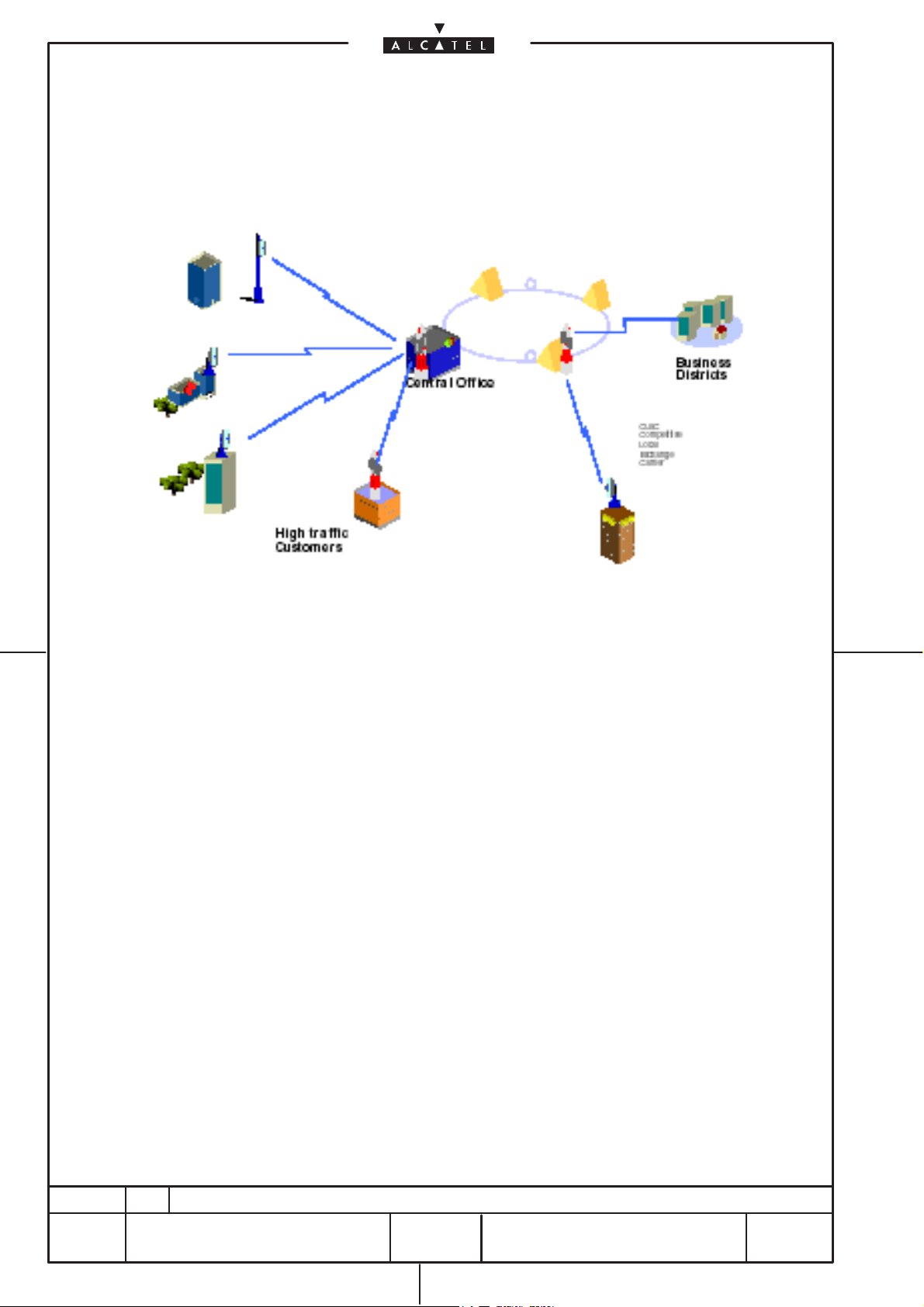
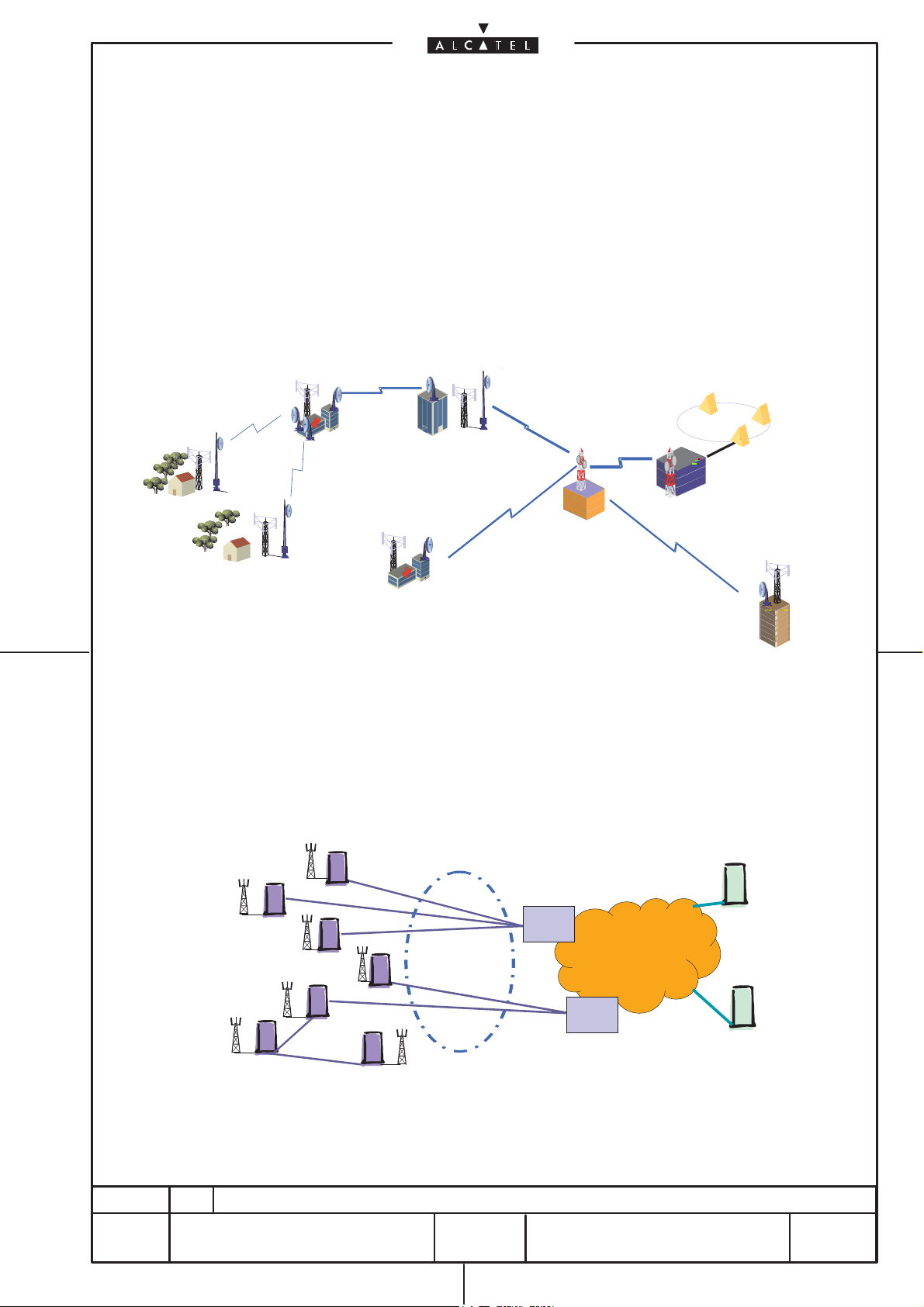
1–1.3.2 Fixed access networks for Public Telecom or CLECs
[1] Basic access applications
The Alcatel 9400 AWY is used for urban/sub–urban connections of high traffic customers or business
districts: with NxE1/NxDS1 or E3/DS3 capacity covering distances from a few km up to 30 km.
document, use and communication of its contents
All rights reserved. Passing on and copying of this
not permitted without written authorization from Alcatel.
Fig. 3. Wireless Access for large customers by Public Telecom
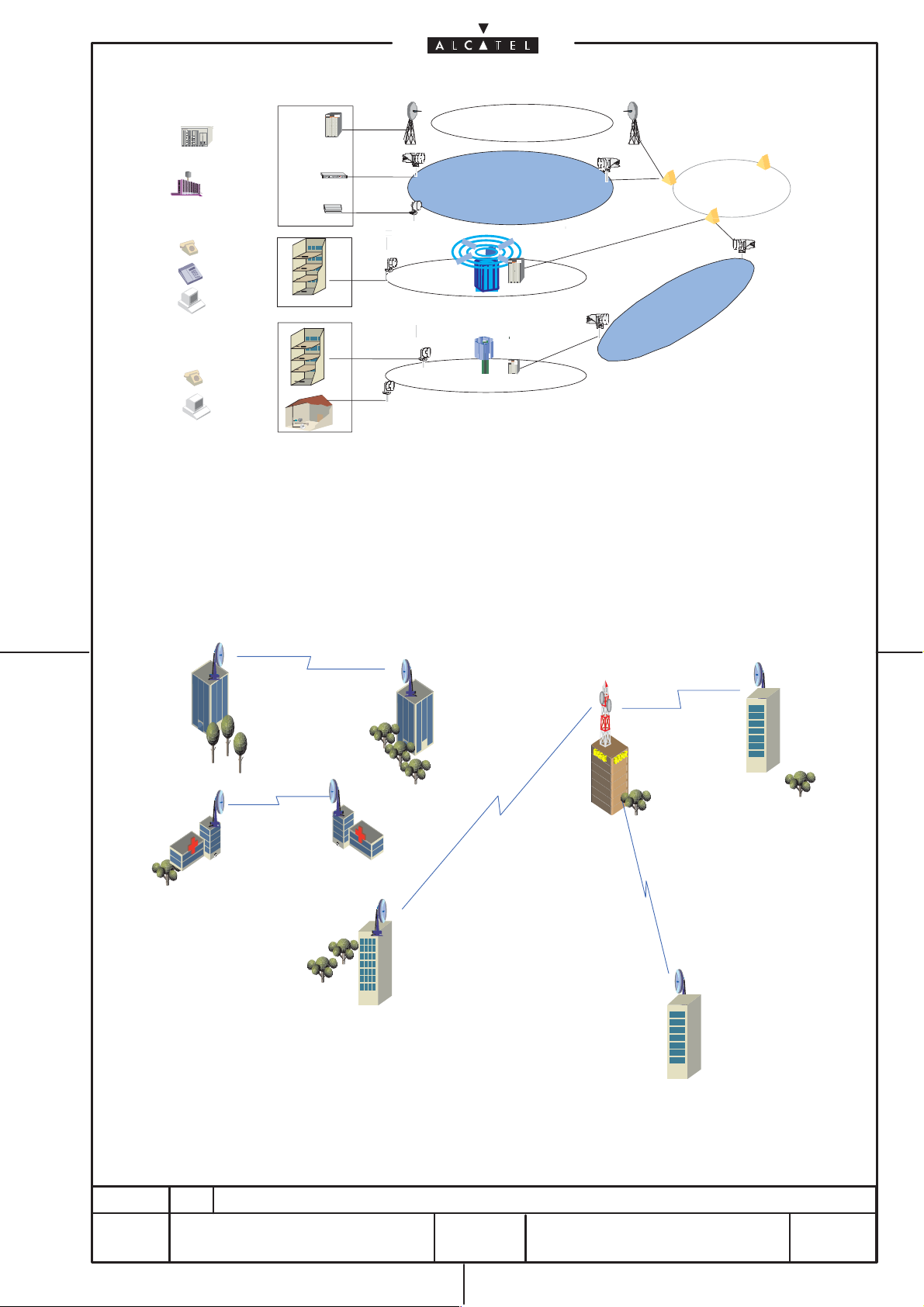
[2] Mixed point to point and point to multipoint fixed radio application
The other applications of Alcatel 9400 AWY are linked to turn–key offers for CLECs broadband
wireless networks
• 9400 AWY is used in networks which are similar to the standard private networks/business
applications of microwave radios:
In very dense area the 9400AWY can be combined with Alcatel LMDS family to provide integrated
access solutions.
The 9400 AWY product provide NxE1/NxDS1 direct connections (leased lines applications) of
subscribers to avoid to congest the LMDS spectrum in one sector or the connection of subscribers
who are out of range with the LMDS cell but whose traffic does not justify the installation of a new
cell.
• 9400 AWY is used to provide E3/DS3 inter–connections between Wireless IP base stations or
between regional low traffic potential LMDS base stations, in order to provide a cost effective
infrastructure transmission solution.
1AA 00014 0004 (9007) A4 – ALICE 04.10
ED
03
268
/3DB 05653 BA AA
22
268
Corporate
PBX
Voice
STM1
STM0
Datas
16x2 Mbit/s
:
BTS/Cellular
2x2
4x2
:
:
2x2
SME
POTS
ISDN
LAN
SoHo/ Residential+
POTS
Internet
High data
document, use and communication of its contents
All rights reserved. Passing on and copying of this
rate
not permitted without written authorization from Alcatel.
Fig. 4. Alcatel 9400 AWY integration in Wireless IP and LMDS network
A9600 (SDH)
4W 1
NMS 1
F
ON / OFF
ESC EXT
ESC EXT
ODU
I/O
URG ATT IDU
4W 2
NMS 2
DEBUG
NURG ODU
RST
ACOI/O
EXT
EXT
ALCTEL
t
A9400 (PDH)
A7390 (LMDS)
A9400 (PDH)
A7385 (WIP)
1–1.3.3 Private voice/data network
The Alcatel 9400AWY is well suited to implement corporate networks, providing inter–PBX (NxE1/NxDS1)
or inter–LAN (E3/DS3) between Universities, Hospitals, Headquarters and branch Office.
Universities
Hospitals
Headquarters
Corporate
Networks
Branch
Branch
Office
Office
1AA 00014 0004 (9007) A4 – ALICE 04.10
ED
03
Fig. 5. Alcatel 9400 AWY integration in Wireless IP and LMDS network
268
23
268
/3DB 05653 BA AA

1–1.4 User interfaces, service channels and additional interfaces
1–1.4.1 User interface
9400 AWY provides the following kinds of user interfaces:
– up to 16xE1 (2.048 Mbit/s) ITU–T Rec. G.703
– up to 16xDS1 (1.544 Mbit/s) ITU–T Rec. G.703
– 1xE3 (34.368 Mbit/s) ITU–T Rec. G.703
– 1xDS3 (44.736 Mbit/s) ANSI T1.102
Note : E1/DS1 and E3/DS3 are in alternative.
1–1.4.2 Service channels
In addition to the main signals, the 9400 AWY family permits the transmission of the following service
channels:
– EOW (IDU access by telephone handset and 2–way party line)
– 1x64 kbit/s G.703 (co–directional) or V.11 (co– or contra–directional)
document, use and communication of its contents
All rights reserved. Passing on and copying of this
not permitted without written authorization from Alcatel.
1–1.4.3 Additional interfaces
The equipment is provided with the following additional interfaces for management and maintenance
purposes:
– 10/100BASE–T LAN access for TMN purposes
– F interface for local Craft Terminal connection
– Summarizing/Housekeeping Alarms
– Alarm/status LEDs.
1AA 00014 0004 (9007) A4 – ALICE 04.10
ED
03
268
/3DB 05653 BA AA
24
268

1–1.5 Equipment architecture
The 9400 AWY system has been designed in a split mount architecture. It consists of three main parts.
– Indoor Unit (IDU) refer to paragraph 1–1.5.1 on page 26
– Outdoor Unit (ODU) refer to paragraph 1–1.5.2 on page 30
– IDU/ODU cable refer to paragraph 1–1.5.3 on page 29
IDU and ODU are connected with a single standard coaxial cable carrying the main traffic, the remote
power supply voltage for the ODU and auxiliary information.
Rack or wall or desk mounting are available for the IDU.
The ODU can be installed on standard poles, wall or pedestal mount, with an appropriate fastening
system, which guarantees the coarse and fine pointing, even when a faulty ODU has to be replaced.
document, use and communication of its contents
All rights reserved. Passing on and copying of this
not permitted without written authorization from Alcatel.
The ODU (one or two depending on the configuration 1+0 or 1+1) incorporates the complete RF
transceiver and can be associated with an integrated antenna (30 cm or 60 cm diameter) or separate
antenna, if a larger diameter is needed. The ODU is capacity–independent and consists of a single cabinet
(size and weight independent on frequency) with a solar shield.
The cabinet is a very compact and robust weatherproof (IP 67) container, designed to be compatible with
hot and very sunny climatic zones.
The ODU can be rapidly installed on standard poles with an appropriate fastening system. The pole
mounting is the same for 1+0 or 1+1 configurations from 13 to 38 GHz.
The ODU is fixed by means of quick latches. This system allows to change the ODU without altering
antenna pointing
The pointing of the antenna can be easily performed with the use of a dedicated service kit. This kit, when
connected to the ODU, provides the received signal level, and the connection to the other station on the link
through a telephone service channel.
1AA 00014 0004 (9007) A4 – ALICE 04.10
ED
03
268
/3DB 05653 BA AA
25
268
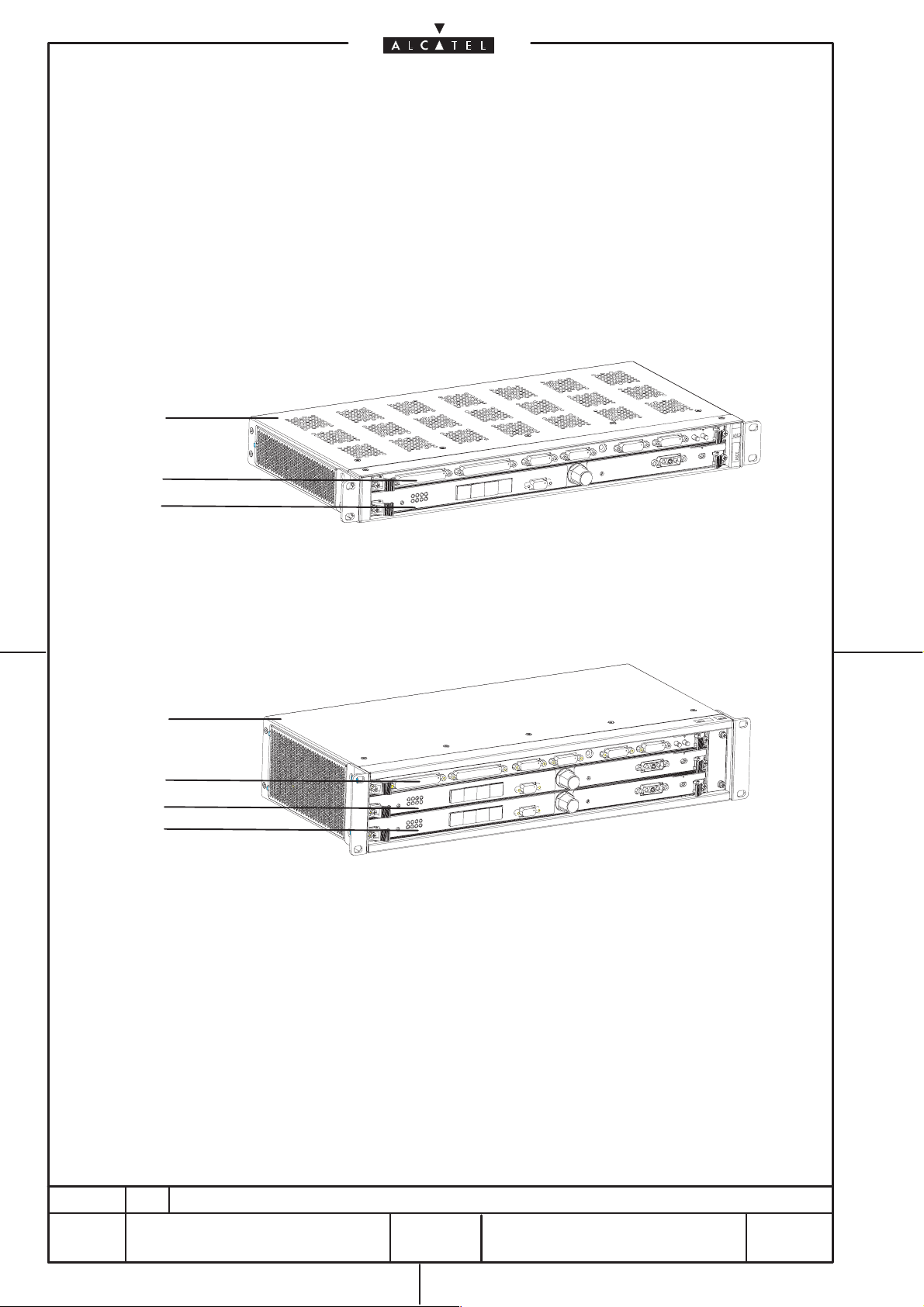
1–1.5.1 IDU (Indoor Unit)
The IDU incorporates the base–band processing and offers tributaries interfaces as well as service
channel and supervision.
The IDU is frequency–independent (same unit from 13 to 38 GHz)
The IDU is available in “1+0 unprotected configuration” and “1+1 protected configuration”.
The “1+1 configuration” shelf can be subequipped to obtain the “1+0 extendible unprotected
configuration”.
The IDU is a single assembly (1U +5 mm high in case of 1+0 Compact version or 2U high in the 1+0 EXT /
1+1 cases).
1+0 IDU
1
2
3
document, use and communication of its contents
All rights reserved. Passing on and copying of this
not permitted without written authorization from Alcatel.
1
2
4
3
1= IDU subrack
2= IDU Access Unit
3= IDU Main Unit
4= IDU Extension Unit
1+1 IDU
Fig. 6. “1+0” and “1+1” IDU shelves
1AA 00014 0004 (9007) A4 – ALICE 04.10
ED
03
268
/3DB 05653 BA AA
26
268

The 1+0 Compact IDU is made up of the following units:
– Access IDU unit
– Main IDU unit
The 1+1 IDU is made up of the following units:
– Access IDU unit
– Main IDU unit
– Extension IDU unit
– Fans unit.
The units housed inside each IDU carry out the following main functions:
[1] Access IDU unit
document, use and communication of its contents
All rights reserved. Passing on and copying of this
not permitted without written authorization from Alcatel.
It allows access for tributaries, alarms and service channels. It includes transformers to match the
tributary impedance and tributary splitting. This unit is common for both 1+0 and 1+1 systems.
[2] Main IDU unit
It includes a DC/DC converter, the Mux/Demux and the cable interface functions for the main channel
and a µP implementing the EC and RC functionalities. This unit is common to both 1+0 and 1+1
systems.
The main functions implemented are:
• E1/DS1 tributary management
• E3/DS3 tributary management
• 64 kbit/s service channel management
• Alarms and Housekeeping management
• Telephone and Engineering Order Wire channels management
• Mux/Demux
• Scrambler/Descrambler
• RS coding/decoding
• Interleaving/De–interleaving
• Cable interface.
The Main IDU unit can be configured by CT/OS for the ETSI market (E1 or E3 tributaries) or for the
ANSI market (DS1 or DS3 tributaries).
The Main IDU unit contains all the interfaces for external links, but does not contain the connectors
for the protected interfaces; these are present on the Access IDU Unit.
The following types of MAIN IDU UNIT are available:
• one for 48 to 60 Vdc power supply (managed from SWP version 1.0.0)
• one for 24 Vdc power supply (managed from SWP version 1.0.2)
1AA 00014 0004 (9007) A4 – ALICE 04.10
ED
Starting from SWP R.1.1 (to be confirmed), an additional plug–in (DATA CARD) could be optionally
plugged onto the main IDU implementing Ethernet functionalities.
03
27
268
268
/3DB 05653 BA AA
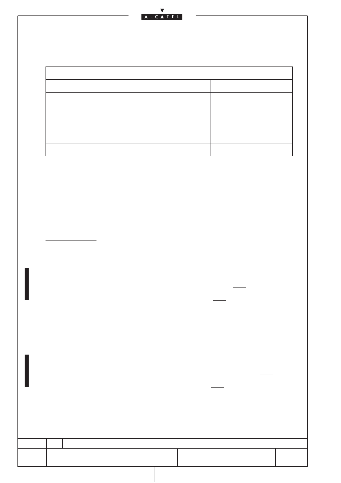
[3] Flash Card
A FLASH CARD is plugged into the Main board giving the maximum capacity for the tributaries and
the modulation type as reported in the following Tab. 2. (5 possible types of Flash card).
Tab. 2. Available Flash cards
NAME Capacity Modulation
Full Flexible Flash Card All All
16E1DS1 16QAM Flash Card Up to 16E1DS1 16QAM
4E1 16QAM Flash Card Up to 4E1 16QAM
16E1DS1 4QAM Flash Card Up to 16E1DS1 4QAM
4E1DS1 4QAM Flash Card Up to 4E1/DS1 4QAM
Notes:
1 ) A 16 QAM Flash card does not allow the transmission of a 4 QAM signal.
2 ) A 4xE1/DS1 Flash Card does not allow the transmission of a capacity greater than 4xE1/DS1.
document, use and communication of its contents
All rights reserved. Passing on and copying of this
not permitted without written authorization from Alcatel.
3 ) As far as E3/DS3 tributary rate is concerned, only the Full Flexible Flash card can be selected.
4 ) The Full Flexible Flash Card allows the transmission of whatever capacity and modulation.
[4] Extension IDU unit
This unit is present in 1+1 systems only and its functions are as those of the Main unit, but for channel
0, except the Equipment Controller function.
The following types of EXTENSION IDU UNIT are available:
• one for 48 to 60 Vdc power supply (managed from SWP version 1.0.0)
• one for 24 Vdc power supply (managed from SWP version 1.0.2)
[5] Fans unit
For the 1+0 EXTENDABLE and 1+1 versions, due to the dense packing, a fans unit is present; this
unit can be easily replaced from the front panel as well as the units above.
[6] Power supply
The PSU function is integrated in the Main/Extension units and can be of the following types:
• Floating (48 to 60) Vdc nom. ± 20% (presently available from SWP version 1.0.0)
1AA 00014 0004 (9007) A4 – ALICE 04.10
ED
• Floating 24 Vdc nom. ± 20% (available from SWP version 1.0.2)
• Floating full range (24–60) V nom. ± 20% (envisaged in future)
03
268
28
268
/3DB 05653 BA AA

1–1.5.2 ODU (Outdoor Unit)
a ) ODU unit
The ODU consists of a cabinet including the modem + transceiver of a channel. The ODU family
operates from 13 GHz to 38 GHz. The mechanical structure utilizes an outdoor water–resistant IP67
cabinet (see chapter 2–3 on page 73 for drawings).
The mechanical solution is the same for the 13 to 38 GHz frequency bands, while the only differences
among the frequency bands are related to the diplexer and the RF section.
All configurations are available for each frequency band.
The ODU presents one output port at which a single polarization integrated antenna (30 cm or 60
cm diameter) or a waveguide for not integrated antenna connection can be connected.
The ODU is capacity–independent.
The ODU consists of subunits which carry out the following main functions (see Fig. 7. on page 30):
document, use and communication of its contents
All rights reserved. Passing on and copying of this
not permitted without written authorization from Alcatel.
[1] Modem: It consists of a base–band part and an IF part. The main functions are:
– Cable interface: DC splitting, echo cancellation, clock recovery
– HDB3 coding/decoding
– Modulation and demodulation
– Digital to analog conversion
– Analogue filtering
– Up–conversion in Tx side in the frequency range of 1 GHz to 2.1 GHz
– Down–conversion in Rx side from 675 MHz to base band
– Control function for hardware configuration and dialog with the IDU.
[2] Front–End
. The main functions are:
– AGC IF amplification
– Up–conversion to the RF Tx channel frequency
– Transmit power control range of 30 dB
– RF loop–back
– Double mixers at Rx side (the frequency of the signal sent to the modem board is 675 MHz
whatever the frequency band and shifter).
[3] Synthesizer unit
– The RF LO in the overall frequency range of 3.8 GHz to 5.7 GHz
– The IF LO in the frequency range of 1.0 GHz to 2.1 GHz
1AA 00014 0004 (9007) A4 – ALICE 04.10
[4] Power Supply Unit
[5] Diplexer
signals and harmonics. It consists of two band–pass filters: one for the Rx and one for the Tx.
The rejection between these two parts is more than 70 dB. The insertion losses are less than
2 dB.
b ) Solar shield
Even if the ODU has been designed to work without solar shield, this one is always delivered with
each ODU.
N.B. Note : the ODU is qualified for a room temperature of +55
ED
03
: it is screwed on the Front End box
: it is inserted between the front end and the antenna. Its scope is to filter all interfering
0
C maximum. In case of solar
radiation (1120 W/m2), the maximum room temperature is reduced to +40
0
C (ETS 300
019–2–4.1). It assumes that the protection of the solar shield is 15 0C.
29
268
268
/3DB 05653 BA AA
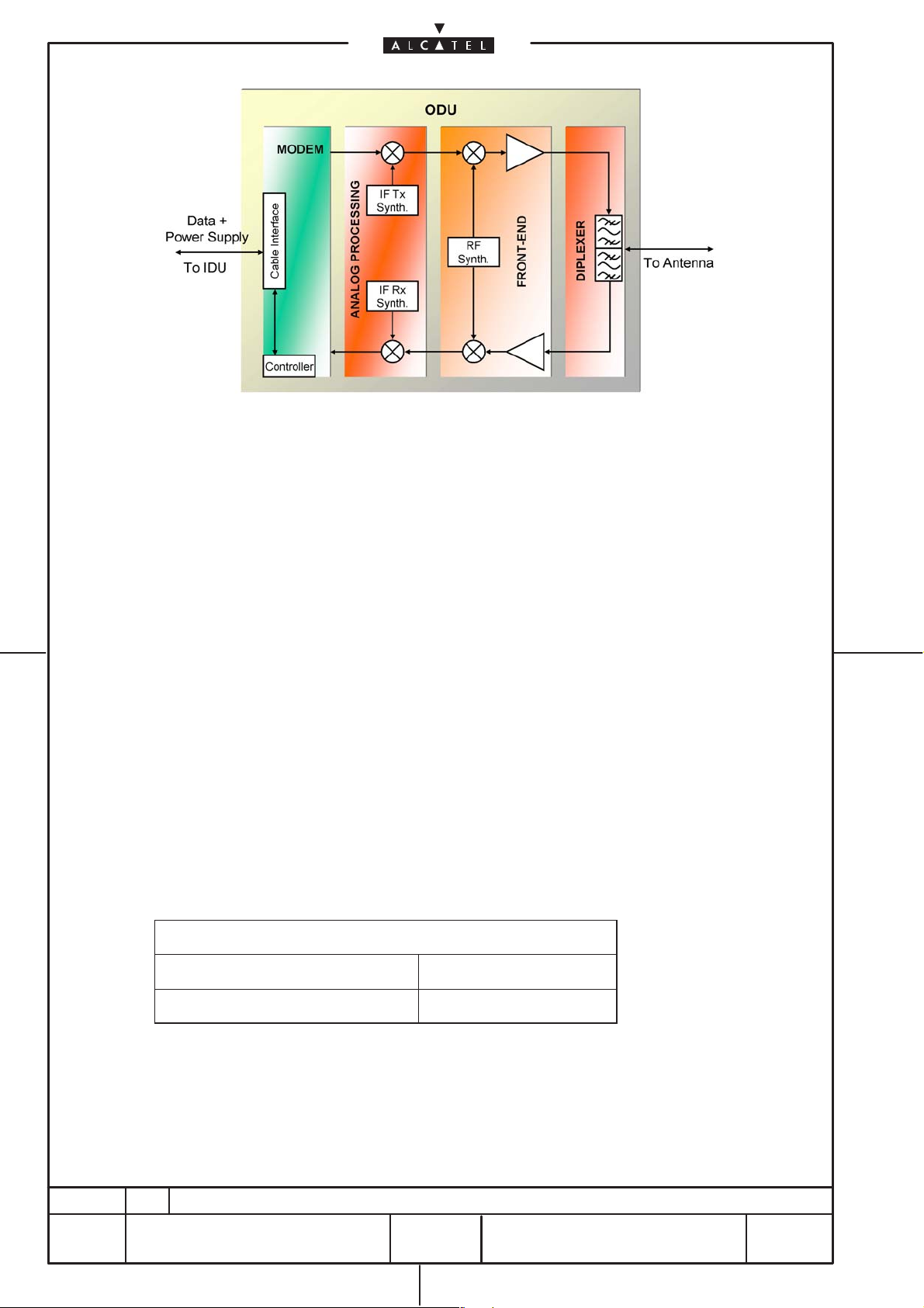
Fig. 7. ODU block diagram
c ) ODU Coupler
The ODU coupler (shown in Fig. 23. on page 86) is used in the following equipment configuration:
• 1+1 HSB
• 1+1 FD CP
The 1+0 configuration is comprised of a simple diplexer inside the cabinet while the protected
configurations (1+1) are always comprised of two cabinets and:
• one 3 dB symmetric or 1/10 dB asymmetric coupler for HSB configuration
• one 3 dB symmetric coupler for FD with single polar antenna
The couplers are connected between the cabinets and the antenna.
1–1.5.3 IDU–ODU cable
The connection between the IDU and the ODU is realized with a single coaxial cable and N–50 ohm
connectors.
On this cable the following signals are present:
– DC voltage to the remote power supply of the ODU;
– HDB3 Tx signal;
– HDB3 Rx signal.
The HDB3 signal is an aggregate signal including the main signal, auxiliary signal and the IDU–ODU
service channels.
The bit rate of the aggregate signal is listed in the following table.
document, use and communication of its contents
All rights reserved. Passing on and copying of this
not permitted without written authorization from Alcatel.
1AA 00014 0004 (9007) A4 – ALICE 04.10
Tab. 3. Bit rate of the IDU–ODU signal on the cable
ETSI (2 to 16xE1, E3) 39.168 Mbit/s
ANSI (4 to 16xDS1, DS3) 57.120 Mbit/s
The IDU–ODU cable is a standard coaxial cable (Filotex 390998) and allows a guaranteed maximum
distance between IDU and ODU of 304 m (1000 feet).
ED
03
30
268
268
/3DB 05653 BA AA
 Loading...