

Page 1
Directions for Use
Alaris® System
(with PC Unit, Model 8000)
Supports Guardrails® Suite MX with Guardrails® Point-Of-Care software and v9 Operating System software.
February 2007
FU
S
N
ONI
T
O
M
R
S
M
T
R
A
N
A
L
A
D
B
Y
FU
S
E
IN
S
T
A
M
N
R
D
A
B
L
A
Y
E
I
S
T
A
M
N
R
D
A
B
L
A
Y
FU
S
E
N
I
S
T
A
N
M
D
R
A
L
A
B
Y
%SpO
PULSE (BPM)
2
CHANNEL
SELECT
MONITOR
CHANNEL
OFF
RATE (mL/h)
CHANNEL
SELECT
PAUSE
CHANNEL
OFF
RESTART
SILENCE
OPTIONS
CLEAR
RATE (mL/h)
CHANNEL
SELECT
PAUSE
CHANNEL
SYSTEM
ON
1
2
4
7
3
6
5
8
0
ENTER
9
CANCEL
.
OFF
RESTART
RATE(mL/h)
CHANNEL
SELECT
PAUSE
CHANNEL
OFF
RESTART
Alaris® Products
Page 2

Table of Contents
Each of the Alaris® product-specific Sections has its own table of contents.
General Contact Information
. . . . . . . . . . . . . . . . . . . . . . . . . . . . . . . . . . . . . . . . . . . . . . . . . . . . . . . . . . . . . . . . . . . . i
Introduction . . . . . . . . . . . . . . . . . . . . . . . . . . . . . . . . . . . . . . . . . . . . . . . . . . . . . . . . . . . . . . . . . . . . . . . . . . . . . . . . . . . . . . . . . ii
Installation. . . . . . . . . . . . . . . . . . . . . . . . . . . . . . . . . . . . . . . . . . . . . . . . . . . . . . . . . . . . . . . . . . . . . . . . . . . . . . . . . . . . . . . . . . . iv
PC Unit . . . . . . . . . . . . . . . . . . . . . . . . . . . . . . . . . . . . . . . . . . . . . . . . . . . . . . . . . . . . . . . . . . . . . . . . . . . . . . . . . . . . . . . . . . . . . . 1
Pump and Syringe Modules . . . . . . . . . . . . . . . . . . . . . . . . . . . . . . . . . . . . . . . . . . . . . . . . . . . . . . . . . . . . . . . . . . . . . 2
PCA Module . . . . . . . . . . . . . . . . . . . . . . . . . . . . . . . . . . . . . . . . . . . . . . . . . . . . . . . . . . . . . . . . . . . . . . . . . . . . . . . . . . . . . . . . 3
SpO2 Module. . . . . . . . . . . . . . . . . . . . . . . . . . . . . . . . . . . . . . . . . . . . . . . . . . . . . . . . . . . . . . . . . . . . . . . . . . . . . . . . . . . . . . . . 4
EtCO2 Module . . . . . . . . . . . . . . . . . . . . . . . . . . . . . . . . . . . . . . . . . . . . . . . . . . . . . . . . . . . . . . . . . . . . . . . . . . . . . . . . . . . . . . 5
Auto-ID Module . . . . . . . . . . . . . . . . . . . . . . . . . . . . . . . . . . . . . . . . . . . . . . . . . . . . . . . . . . . . . . . . . . . . . . . . . . . . . . . . . . . . 6
Nurse Call Accessory. . . . . . . . . . . . . . . . . . . . . . . . . . . . . . . . . . . . . . . . . . . . . . . . . . . . . . . . . . . . . . . . . . . . . . . . . . . . . 7
Communications Interface Board Accessory. . . . . . . . . . . . . . . . . . . . . . . . . . . . . . . . . . . . . . . . . . . . . . . . . 8
Appendix
Maintenance. . . . . . . . . . . . . . . . . . . . . . . . . . . . . . . . . . . . . . . . . . . . . . . . . . . . . . . . . . . . . . . . . . . . . . . . . . . . . . . . . . . . . . A-1
Cleaning . . . . . . . . . . . . . . . . . . . . . . . . . . . . . . . . . . . . . . . . . . . . . . . . . . . . . . . . . . . . . . . . . . . . . . . . . . . . . . . . . . . . . . . A-1
Service Information
Warranty . . . . . . . . . . . . . . . . . . . . . . . . . . . . . . . . . . . . . . . . . . . . . . . . . . . . . . . . . . . . . . . . . . . . . . . . . . . . . . . . . . . . . . . A-3
Regulations and Standards . . . . . . . . . . . . . . . . . . . . . . . . . . . . . . . . . . . . . . . . . . . . . . . . . . . . . . . . . . . . . . . . . . . . . A-5
Compliance
Trademarks . . . . . . . . . . . . . . . . . . . . . . . . . . . . . . . . . . . . . . . . . . . . . . . . . . . . . . . . . . . . . . . . . . . . . . . . . . . . . . . . . . . . A-14
. . . . . . . . . . . . . . . . . . . . . . . . . . . . . . . . . . . . . . . . . . . . . . . . . . . . . . . . . . . . . . . . . . . . . . . . . . . . . . . . . . . . A-5
. . . . . . . . . . . . . . . . . . . . . . . . . . . . . . . . . . . . . . . . . . . . . . . . . . . . . . . . . . . . . . . . . . . . . . . . . . . . . A-2
Order Numbers:
Electronic Copy: 10015905
Printed Copy: 10110697 ©2006, 2007 Cardinal Health, Inc. or one of its subsidiaries. All rights reserved.
Alaris® System (with v9 Model 8000) DFU
Page 3

Cardinal Health
®
Alaris
10221 Wateridge Circle
Products
San Diego, California
cardinal.com/alaris
Maintenance and service information support; troubleshooting.
General Contact Information
92121
Customer Advocacy - North America
Clinical and technical feedback.
Phone: 800.854.7128, Ext. 7812
E-Mail: CustomerFeedback@cardinal.com
Technical Support - North America
United States - Phone:
858.458.6003
800.854.7128, Ext. 6003
Within Canada: 800.387.8309
From United States: 800.908.9918
Canada - Phone:
Customer Care - North America
Instrument return, service assistance, and order placement.
United States - Phone: 800.482.4822 Canada - Phone: 800.387.8309
Alaris® System (with v9 Model 8000) DFU
i
Page 4

Introduction
The Alaris® PC unit Section of this Directions for Use ("DFU")
provides procedures and information applicable to the Alaris
System and the PC Unit. Each of the other major Sections
provides product-specific procedures and information.
®
The Alaris
System is a modular system intended for adult,
pediatric and neonatal care in today’s growing professional
healthcare environment. It consists of the PC Unit, the
®
Guardrails
Suite MX, and up to 4 detachable infusion and/or
monitoring modules (channels). The Auto-ID Module can be
included as a fifth module.
®
Guardrails
Suite MX for the Alaris® System brings a new
level of medication error prevention to the point of patient
®
care. The Guardrails
Suite MX features medication dosing,
concentration delivery rate and optional initial programming
guidelines for up to
15 patient-specific care areas, referred
to as profiles. Each profile contains a specific Drug Library
and channel labels, as well as instrument configurations
appropriate for the care area. Optional drug-specific Clinical
Advisories provide visual messages. Dosing limits for each
®
Guardrails
drug entry may be a Hard Limit that cannot be
overridden during infusion programming and/or a Soft Limit
that can be overridden, based on clinical requirements.
®
WARNING
Read all instructions before using
®
the Alaris
System.
CAUTION
nly
O
A Data Set is developed and approved by the facility’s own
-
PC
multi-disciplinary team using the Editor Software, the
authoring tool. A Data Set is then transferred to the Alaris
based
®
System by qualified personnel. The approved Data Sets are
maintained by the Editor Software for future updates and
reference.
Information about an Alert that occurs during use is stored
within the PC Unit, and can be accessed using the CQI
Reporter.
®
Documentation provided with Alaris
System products
may reference product not present in your facility or not yet
available for sale in your area.
A superscript number (for example,
information provided as a
NOTE at the end of the procedure.
) identifies additional
ii
Alaris® System (with v9 Model 8000) DFU
Page 5

Introduction (Continued)
WARNINGS AND CAUTIONS:
Product-specific warnings and cautions, covered in the
applicable Sections of this DFU
safely and effectively use the Alaris
, provide information needed to
®
System.
A
DANGER
is an alert to an imminent hazard which
could result in serious personal injury and/or product damage
if proper procedures are not followed.
WARNING
A
is an alert to a potential hazard which could
result in serious personal injury and/or product damage if
proper procedures are not followed.
CAUTION
A
is an alert to a potential hazard which could
result in minor personal injury and/or product damage if proper
procedures are not followed.
DEFINED TERMS:
The following table identifies the defined terms used throughout
this document for certain products and product features.
Product / Feature Defined Term
Alaris® Auto-ID module Auto-ID Module
Alaris® EtCO2 module EtCO2 Module
Alaris® Mobile Systems Manager Mobile Systems Manager
Alaris® PCA module PCA Module
Alaris® PC point-of-care unit PC Unit
Alaris® Pump module Pump Module
Alaris® SpO2 module SpO2 Module
Alaris® Syringe module Syringe Module
Alaris® System Maintenance System Maintenance
Alaris® Systems Manager Systems Manager
Guardrails® alert Alert
Guardrails® clinical advisory Clinical Advisory
Guardrails® CQI Reporter CQI Reporter
Guardrails® data set Data Set
Guardrails® drug library Drug Library
Guardrails® Editor Editor Software
Guardrails® hard limit Hard Limit
Guardrails® IV fluid IV Fluid
Guardrails® limit Limit
Guardrails® PCA pause protocol PCA Pause Protocol
Guardrails® soft limit Soft Limit
SmartSite® needle-free valve Needle-Free Valve
SmartSite® positive bolus needle-free valve Needle-Free Valve
Alaris® System (with v9 Model 8000) DFU
iii
Page 6

Installation
Instruments are tested and calibrated before they are
packaged for shipment. To ensure proper operation after
shipment, it is recommended that an incoming inspection be
performed before placing the instrument in use.
Prior to placing the Alaris
®
System in use:
1. Perform check-in procedure using System Maintenance
software.
2. Verify whether or not Profiles feature has been enabled
(see PC Unit Section, "System Options", "System
Configurations").
NOTE:
To enable the Profiles feature, a hospital-defined best-practice
Data Set must be uploaded to the PC Unit.
iv
Alaris® System (with v9 Model 8000) DFU
Page 7
Alaris® PC Unit
Model 8000
SILENCE
OPTIONS
CLEAR
SYSTEM
ON
1
2
4
7
3
6
5
8
0
ENTER
9
CANCEL
.
Alaris® System (with v9 Model 8000) DFU, Section
1
Page 8

Page 9

Table of Contents
GETTING STARTED
INTRODUCTION................................................................................................................................................................................................. 1-1
GENERAL SETUP AND OPERATION
ATTACHING AND DETACHING MODULES .......................................................................................................................................... 1-3
Attaching Module(s) ................................................................................................................................................................................ 1-3
Detaching Module(s) ............................................................................................................................................................................... 1-4
Adding Module(s) While System is Powered On
START -UP
.............................................................................................................................................................................................................. 1-5
Powering On System .............................................................................................................................................................................. 1-5
Responding to Maintenance Reminder .......................................................................................................................................... 1-6
Adjusting Display Contrast
................................................................................................................................................................... 1-6
Selecting New Patient and Profile Options ................................................................................................................................... 1-7
Adjusting Audio Volume
........................................................................................................................................................................ 1-9
Locking/Unlocking Tamper Resist .................................................................................................................................................... 1-10
POWER OFF SYSTEM .................................................................................................................................................................................... 1-11
SYSTEM OPTIONS
........................................................................................................................................................................................... 1-11
Display Contrast ....................................................................................................................................................................................... 1-11
Patient ID ..................................................................................................................................................................................................... 1-12
Clinician ID .................................................................................................................................................................................................. 1-14
Power Down All Channels
Anesthesia Mode
Battery Runtime
..................................................................................................................................................................................... 1-16
........................................................................................................................................................................................ 1-19
System Configurations
.................................................................................................................................................................... 1-15
.......................................................................................................................................................................... 1-19
Serial Numbers ......................................................................................................................................................................................... 1-21
Software Versions ................................................................................................................................................................................... 1-22
Time of Day ................................................................................................................................................................................................ 1-23
Network Status ......................................................................................................................................................................................... 1-24
Wireless Connection .............................................................................................................................................................................. 1-26
Data Set Status ......................................................................................................................................................................................... 1-27
Maintenance Due ..................................................................................................................................................................................... 1-28
........................................................................................................................ 1-4
GENERAL INFORMATION
WARNINGS AND CAUTIONS .............................................................................................................................. ........................................ 1-31
General ......................................................................................................................................................................................................... 1-31
Electromagnetic Compatibility ............................................................................................................................................................ 1-32
FEATURES AND DISPLAYS ......................................................................................................................................................................... 1-33
Features and Definitions ....................................................................................................................................................................... 1-33
Operating Features, Controls, Indicators ...................................................................................................................................... 1-35
Displays ........................................................................................................................................................................................................ 1-37
SYSTEM CONFIGURABLE SETTINGS .................................................................................................................................................. 1-38
SPECIFICATIONS AND SYMBOLS ........................................................................................................................................................... 1-39
Specifications ............................................................................................................................................................................................ 1-39
Symbols ....................................................................................................................................................................................................... 1-40
Alaris® System (with v9 Model 8000) DFU
Table of Contents i
PC Unit Section
Page 10

TROUBLESHOOTING AND MAINTENANCE
GENERAL .............................................................................................................................................................................................................. 1-43
ALARM, ERRORS, MESSAGES
Definitions
................................................................................................................................................................................................... 1-43
Audio Characteristics
Alarms ........................................................................................................................................................................................................... 1-45
Errors............................................................................................................................................................................................................. 1-45
Messages .................................................................................................................................................................................................... 1-46
STORAGE
.............................................................................................................................................................................................................. 1-47
BATTERY CARE AND MAINTENANCE
Battery Type and Charging .................................................................................................................................................................. 1-47
Battery Charge .......................................................................................................................................................................................... 1-48
Battery Care
............................................................................................................................................................................................... 1-48
Battery Cautions and Disposal .......................................................................................................................................................... 1-48
INSPECTION REQUIREMENTS
................................................................................................................................................................. 1-43
............................................................................................................................................................................. 1-44
.................................................................................................................................................. 1-47
................................................................................................................................................................. 1-49
ii Table of Contents
Alaris® System (with v9 Model 8000) DFU
PC Unit Section
Page 11

Introduction
Getting Started
This Section of the DFU provides PC Unit (Model 8000) and
®
Alaris
System instructions and information. It is used in
conjunction with:
• PC Unit / Pump Module Technical Service Manual
• Product-specific sections of this
• System Maintenance software (and its instructions) for Alaris®
System check-in, maintenance, and wireless configuration
DFU
The PC Unit is the core of the Alaris® System and provides
a common user interface for programming infusions and
monitoring, which helps to reduce complexity at the point of
care.
Alarms, Errors, Messages: See "Troubleshooting and
Maintenance" for specific PC Unit alarms, errors and
messages.
Contraindications: None known.
Electromagnetic Environment: See "Appendix" Section of
this DFU ("Regulations and Standards", "Compliance").
WARNING
Read all instructions, including
those for the attached module(s) and
applicable accessories, before using
®
the Alaris
System.
CAUTION
nly
O
Alaris® System (with v9 Model 8000) DFU
PC Unit Section
Getting Started 1-1
Page 12

THIS PAGE
INTENTIONALLY
LEFT BLANK
1-2 Getting Started
®
Alaris
System (with v9 Model 8000) DFU
PC Unit Section
Page 13

General Setup and Operation
Attaching and Detaching Module(s)
Modules can be attached to either side of the PC Unit or to
either side of another module. The process to attach or detach
is the same for either side, whether attaching/detaching
to/from a PC Unit or another module.
Attaching Module(s)
1. Position free module at a 45° angle, aligning IUI
connectors.
2. Rotate free module down against PC Unit or attached
module, until release latch snaps in place.
IUI Connectors
45°
WARNING
When properly secured/snapped, the
release latch provides a very secure
connection between modules. If not
properly latched, a module can be
dislodged during operation.
NOTES:
Individual hospital/facility may choose to permanently attach
modules. To remove permanently attached modules, contact
qualified service personnel.
Application of adhesive tape or other materials to the sides of
the PC Unit and modules may prevent proper latching.
The Alaris® System is designed to operate a maximum of 4
infusion or monitoring modules. Modules added in excess of
4 are recognized by the system. The Auto-ID Module can be
included as a fifth module. The module(s) can be attached
in any position; however, when mounted on an IV pole, it is
recommended that a balanced configuration be maintained.
Alaris® System (with v9 Model 8000) DFU
PC Unit Section
Release Latch
General Setup and Operation 1-3
Page 14

Attaching and Detaching Modules (Continued)
Detaching Module(s)
1. Ensure module(s) is powered off before detaching.
2. Push module release latch and then rotate module(s) up
and away from PC Unit or attached module (opposite to
motion shown above) to disengage connectors.
®
• Alaris
module identification (
• Appropriate module position(s) (
remaining module(s) appear on Main Display.
System reidentifies and shows appropriate
A, B, C or D), from left to right.
A, B or C) for
Adding Module(s) While System is Powered On
Add module as described in "Attaching Module(s)".
• System tests module, causing all
LED segments and
indicator lights of displays to illuminate briefly.
• Appropriate module identification display (
A, B, C or D)
illuminates. Modules are always labeled left to right, so if
a module is added to left of other modules, all modules are
reidentified. Module reidentification does
NOT interrupt or
affect infusion or monitoring on active modules.
• Module positions (
NOTE:
If any of the following conditions are observed, the affected
module must be removed from use and inspected by qualified
personnel:
• LED segments are not illuminated on displays during
power-on test.
• Indicator lights do not illuminate.
• Appropriate module identification (A, B, C or D) is not
displayed.
If the affected module operates normally when it is attached
via the alternate
replacement module can be substituted.
A, B, C or D) appear on Main Display.
IUI connector, it may be used until a
1-4 General Setup and Operation
®
Alaris
System (with v9 Model 8000) DFU
PC Unit Section
Page 15

Start-Up
Powering On System
1. Connect PC Unit to an external AC power source.
2. Press
SYSTEM ON.
3. System self test begins:
• Diagnostics test causes all LED display segments
and Status Indicator lights of attached module(s) to
illuminate briefly.
• Power Indicator illuminates.
• Appropriate module identification (A, B, C or D)
displays on attached module(s).
• An Audio tone sounds.
• If PM Reminder option is enabled and scheduled
preventive maintenance is due,
REMINDER screen appears.
MAINTENANCE
• At completion of system-on test, New Patient? screen
appears.
NOTES:
Previous infusion parameters are automatically cleared after
8 hours.
If any of the following conditions are observed, the PC Unit or
the affected attached module must be removed from use and
inspected by qualified personnel:
• LED segments are not illuminated during system-on test.
• Indicator lights do not illuminate.
• Appropriate module identification (A, B, C or D) is not
displayed.
• Audio tone does not sound.
• Main Display does not appear backlit, appears irregular, or
has evidence of a row of pixels not functioning properly.
If the affected module operates normally when it is attached
via an alternate IUI connector, it may be used until a
replacement module can be substituted.
Alaris® System (with v9 Model 8000) DFU
PC Unit Section
General Setup and Operation 1-5
Page 16
Start-Up (Continued)
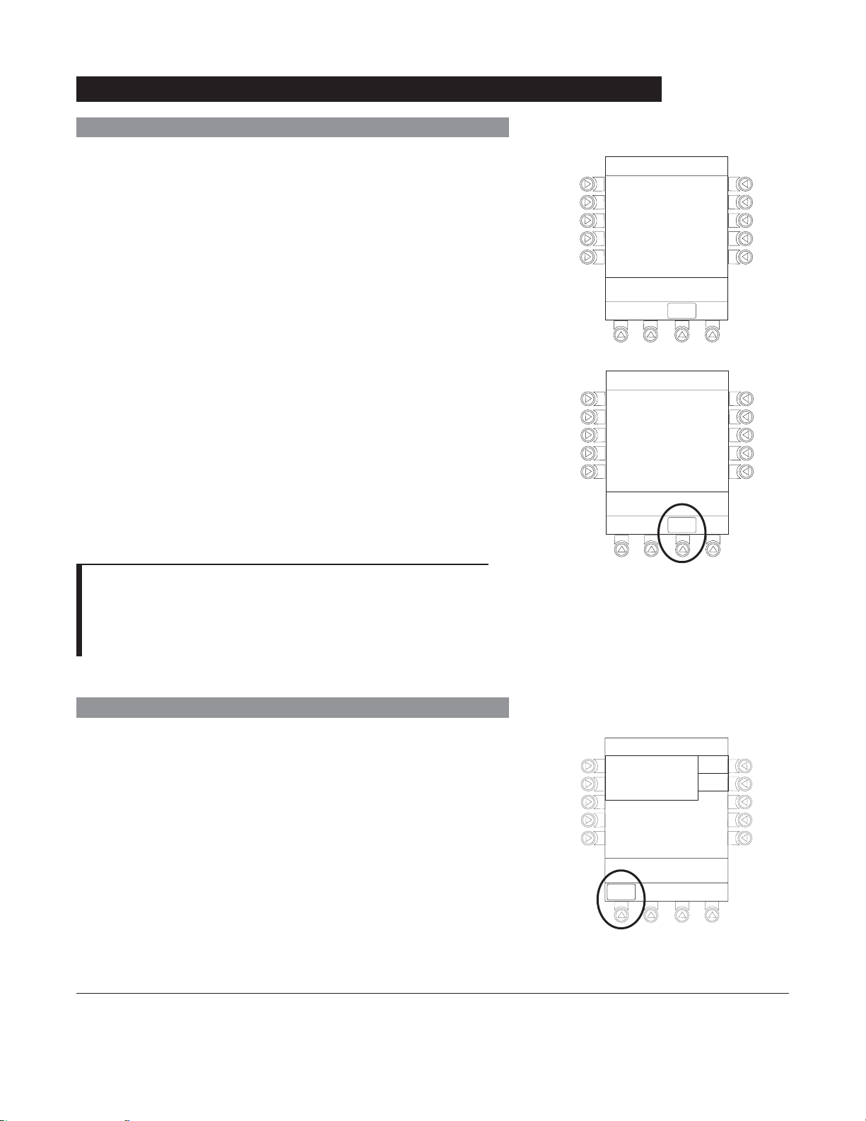
Responding to Maintenance Reminder
If the Preventive Maintenance (PM) Reminder option is enabled
and the PC Unit or an attached module is due for preventive
maintenance, a
MAINTENANCE REMINDER message appears
at power up.
1. Remove and, if needed, replace module requiring
maintenance with a new module (see "Attaching and
Detaching Modules").
®
2. If Alaris
System was powered off to replace PC Unit,
reinitiate start-up process.
OR
If an attached module (such as a Pump Module) was
powered off and removed,
MAINTENANCE REMINDER
display reflects removal of that module. To continue
start–up process, press
CONFIRM soft key.
MAINTENANCE REMINDER
Module(s) due for routine
B
preventive maintenance:
Module A:
MAINTENANCE REMINDER
Module(s) due for routine
B
preventive maintenance:
YYYY-MM-DD
CONFIRM
CONFIRM
NOTES:
If necessary, the reminder can be temporarily bypassed by
pressing the CONFIRM soft key.
Notify the appropriate facility personnel when a
MAINTENANCE REMINDER occurs.
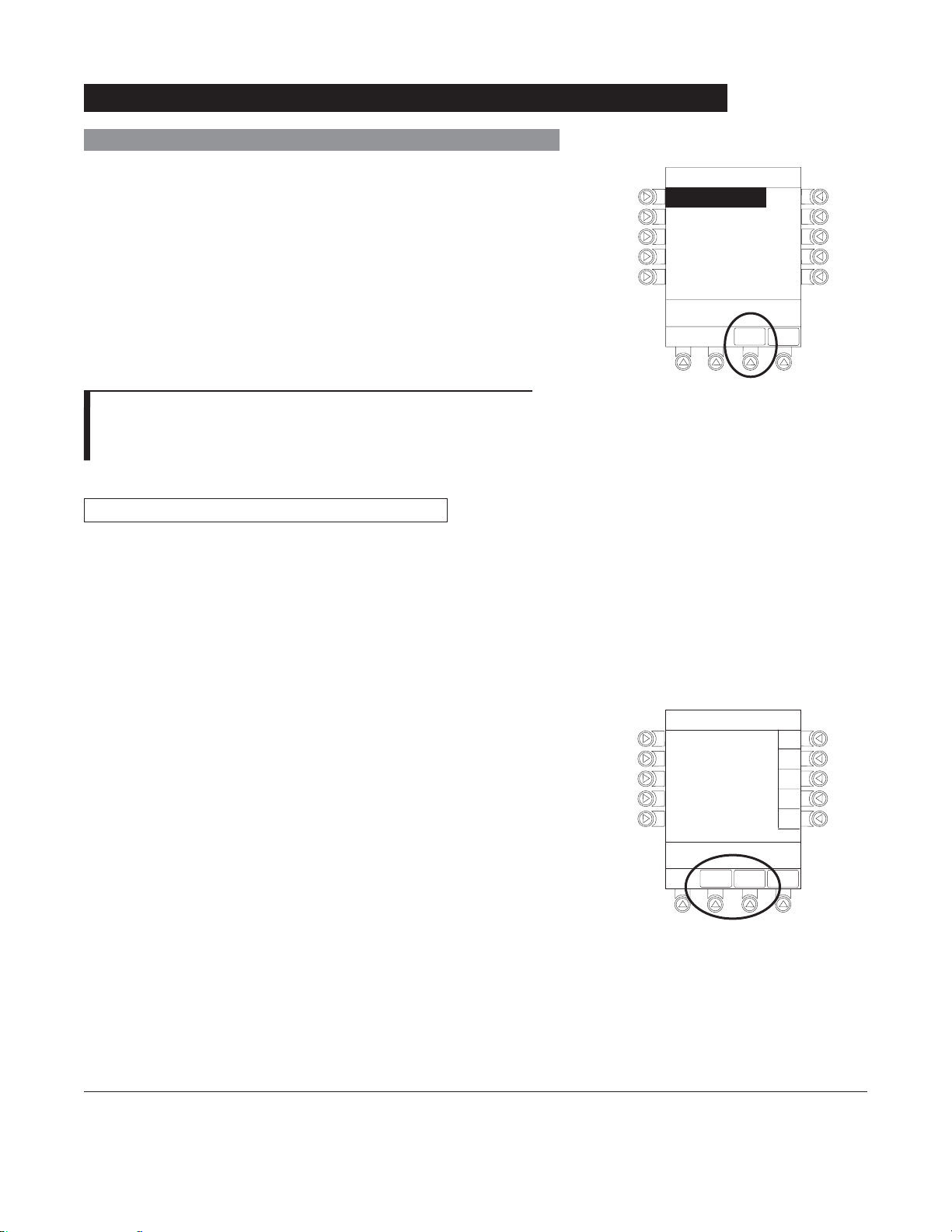
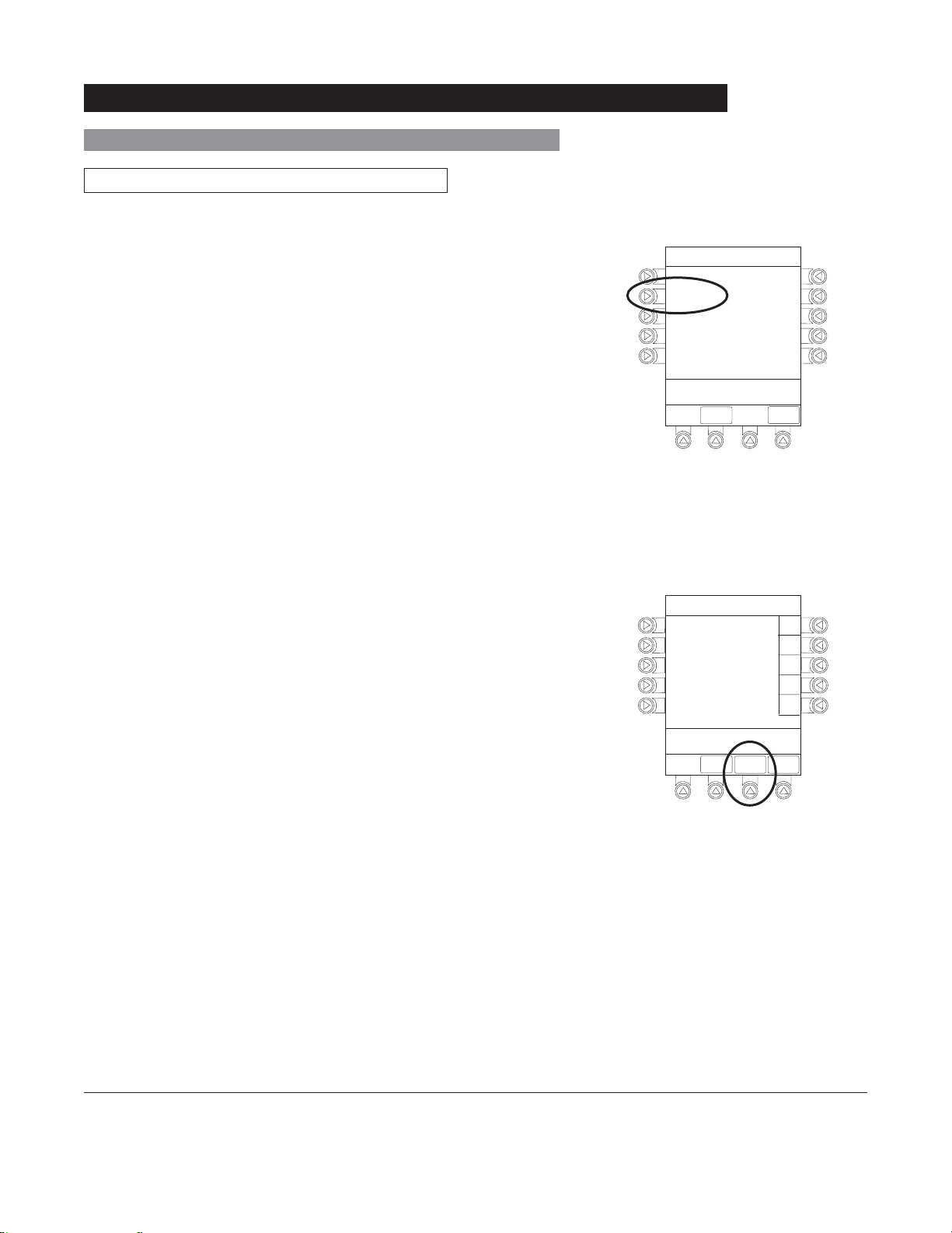
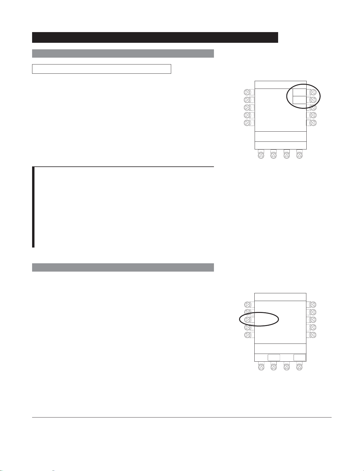
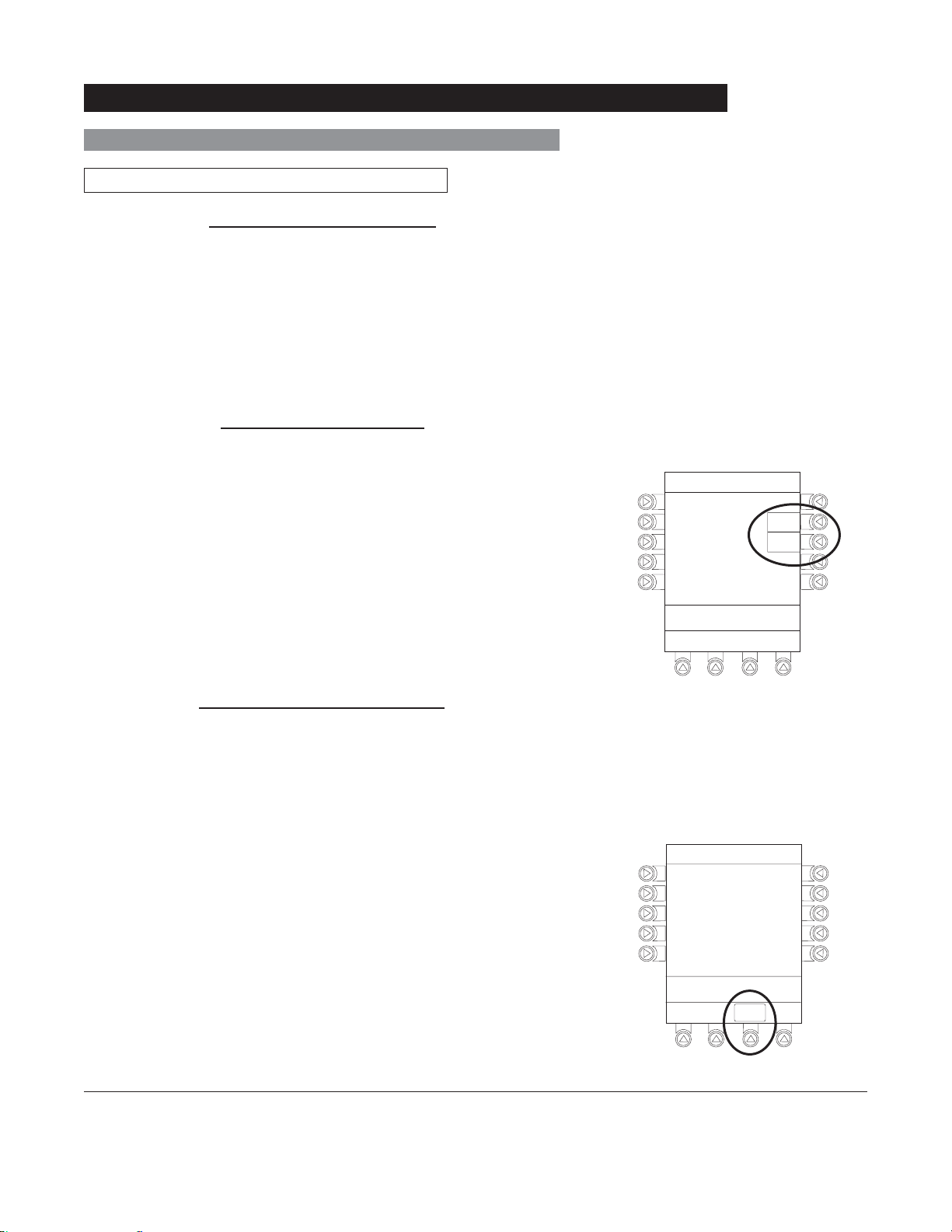
Adjusting Display Contrast
1. Press DISPLAY CONTRST soft key.
Midtown Hospital
NEW PATIENT ?
“Yes” Clears Previous
Patient Data
>Select Yes or No
DISPLAY
CONTRST
Yes
No
1-6 General Setup and Operation
®
Alaris
System (with v9 Model 8000) DFU
PC Unit Section
Page 17
Start-Up (Continued)
Adjusting Display Contrast (Continued)
2. To adjust display for optimum viewing, use Lighter/Darker
soft keys.
3. To return to main screen, press CONFIRM soft key.
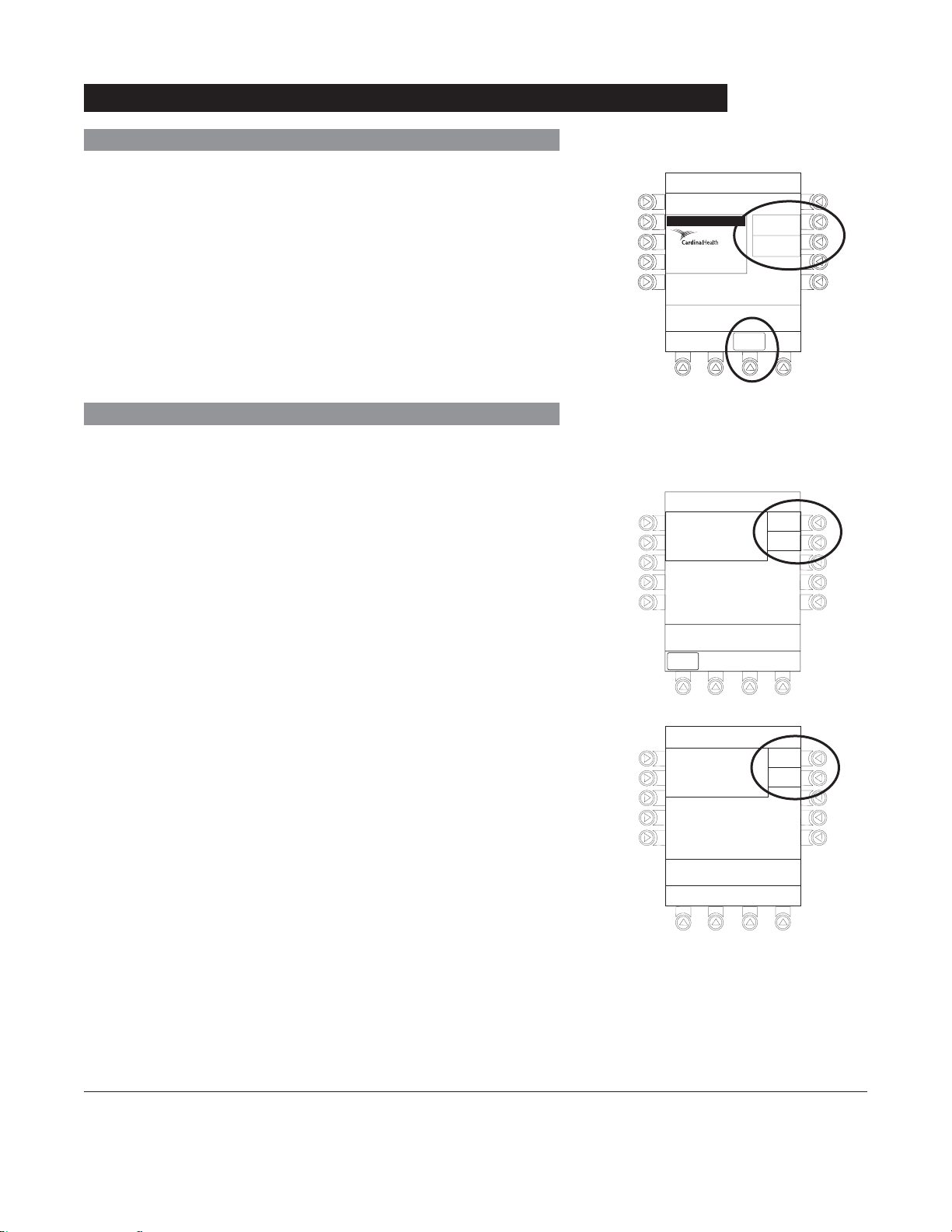
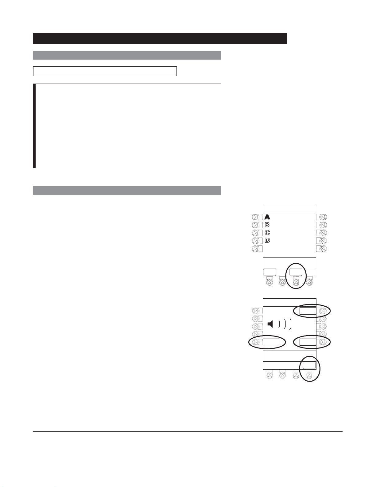
Selecting New Patient and Profile Options
The following procedures assume the Profiles feature is
enabled.
1. Select required
NEW PATIENT? option.
• To indicate programming is for a new patient and clear
all stored patient parameters from memory, press Yes
soft key.
OR
• To confirm programming is for same patient and retain
all stored patient parameters, press No soft key.
♦ Last used profile displays.
System Options
Display Contrast
®
Guardrails Suite MX (v8)
©2001-2005 Cardinal Health, inc.
or one of itssubsidiaries. All rights
reserved. Guardrails® is a registered
trademark of Cardinal Health, inc. or
one of itssubsidiaries.
>Adjust Display to
Desired Contrast
CONFIRM
Midtown Hospital
NEW PATIENT ?
“Yes” Clears Previous
Patient Data
>Select Yes or No
DISPLAY
CONTRST
Lighter
Darker
Yes
No
2. Accept or change current profile:
• To accept current profile, press Yes soft key.
♦ Main screen appears.
• To change profile, press No soft key and continue with
next step.
♦ Profile selection screen appears.
Alaris® System (with v9 Model 8000) DFU
PC Unit Section
Midtown Hospital
Adult ICU
Adult ICU ?
“Yes” Confirms Same
Profile
>Select Yes or No
Yes
No
General Setup and Operation 1-7
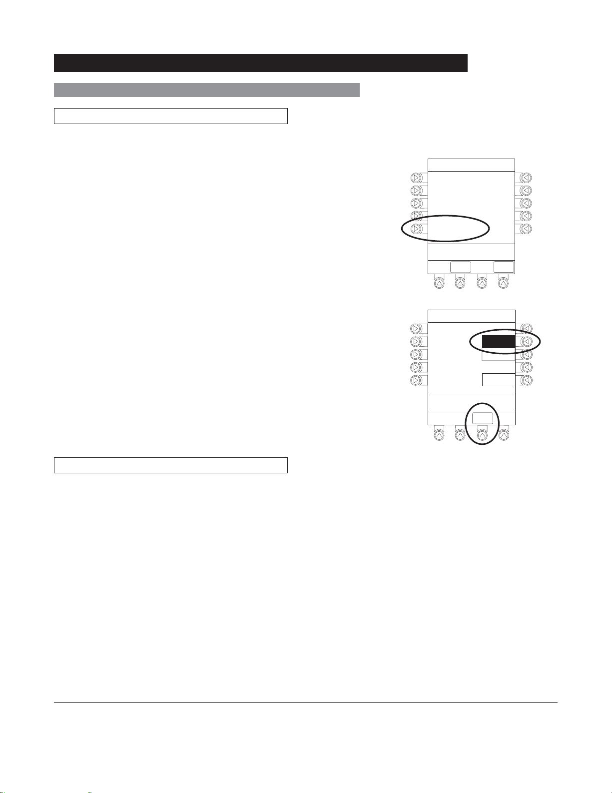
Page 18
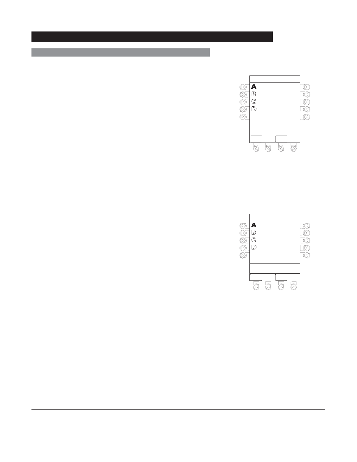
Start-Up (Continued)
Selecting New Patient and Profile Options (Continued)
3. To select a profile, press corresponding left soft key.
4. To confirm profile selection, press CONFIRM soft key.
• Main screen appears.
NOTES:
If the Profiles feature is disabled, the main menu appears.
To view additional choices, press
PAGE DOWN soft key.
Patient ID Entry Feature
The option to enter and display a 16-character alphanumeric
patient identifier is always available. The instrument may
be configured to automatically display the Patient ID Entry
screen during start-up or to provide access only through the
Systems Options menu (see "System Options").
Midtown Hospital
Profiles
Adult ICU
Adult General Care
Neonatal
Peds ICU
Neonatal ICU
>Press CONFIRM
CONFIRM
1of2
PAGE
DOWN
If Yes was selected to indicate programming for a new patient,
perform one of following steps:
• If patient identifier is not required, press
CONFIRM or EXIT
soft key.
• To manually enter patient identifier, use numeric data entry
keys and/or alpha speed keys.
• To scan bar code on patient identification band, see
Auto-ID Module Section of this DFU.
1-8 General Setup and Operation
Patient ID Entry
A
B
C
D
E
________________
>Enter Patient ID and Press
CONFIRM
CONFIRM
EXIT
®
Alaris
System (with v9 Model 8000) DFU
PC Unit Section
A-E
F-J
K-O
P-T
U-Y
PAGE
DOWN
Page 19
Start-Up (Continued)
Selecting New Patient and Profile Options (Continued)
Patient ID Entry Feature (Continued)
NOTES:
An alphanumeric identifier, of up to 16 characters, can be
entered.
Press the soft key next to a letter group to list letters in that
group. Press the soft key next to an individual letter to enter
that letter.
To access the letter "Z" and special characters (hyphen,
underscore, space), press the PAGE DOWN soft key.
To clear an entire entry, press CLEAR key.
To back up a single character at a time, press
Adjusting Audio Volume
CANCEL key.
1. Press AUDIO ADJUST soft key.
2. To change volume to desired level, press either Louder
or Softer soft key. To sample alarm loudness level, press
Test soft key.
3. To return to PC Unit screen, press
MAIN SCREEN soft key.
• After 30 seconds without a key press, Main Display
appears.
Midtown Hospital
Adult ICU
VTBI = 250.0 mL
VOLUME
INFUSED
Audio Volume Adjust
AUDIO
ADJUST
Test
3
Softer
>Change Setting or
Cancel
Louder
MAIN
SCREEN
Alaris® System (with v9 Model 8000) DFU
PC Unit Section
General Setup and Operation 1-9
Page 20
Start-Up (Continued)
Locking/Unlocking Tamper Resist
1. Initiate operation of applicable module(s).
2. Press and hold Tamper Resist Switch, on back of PC Unit,
3 to 4 seconds (see "General Information", "Features
for
and Displays", "Operating Features, Controls, Indicators").
• An advisory tone (if Key Click Audio is enabled)
and a three-second
PANEL LOCKED prompt on Main
Display confirm activation.
• When Tamper Resist is active, keypad panel is locked;
however, clinician may:
♦ Silence audio alarm.
♦ View volume(s) infused.
♦ View and test audio alarm setting.
♦ View selected parameters on attached modules.
Any other key press results in a visual
PANEL LOCKED
prompt and, if Key Click Audio is enabled, an illegal
key–press audio advisory.
3. To unlock keypad panel, press and hold Tamper Resist
Switch for
3 to 4 seconds.
• An advisory tone (if Key Click Audio is enabled) and
a three-second
PANEL UNLOCKED prompt on Main
Display confirm activation.
Midtown Hospital
Adult ICU
VTBI = 250.0 mL
PANEL LOCKED
VOLUME
INFUSED
Midtown Hospital
Adult ICU
VTBI = 250.0 mL
AUDIO
ADJUST
1-10 General Setup and Operation
PANEL UNLOCKED
VOLUME
INFUSED
®
Alaris
System (with v9 Model 8000) DFU
AUDIO
ADJUST
PC Unit Section
Page 21
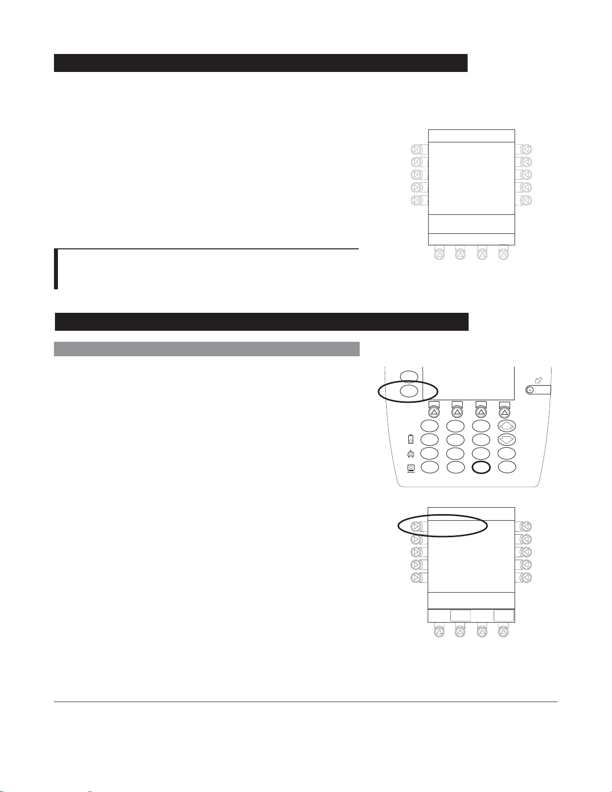
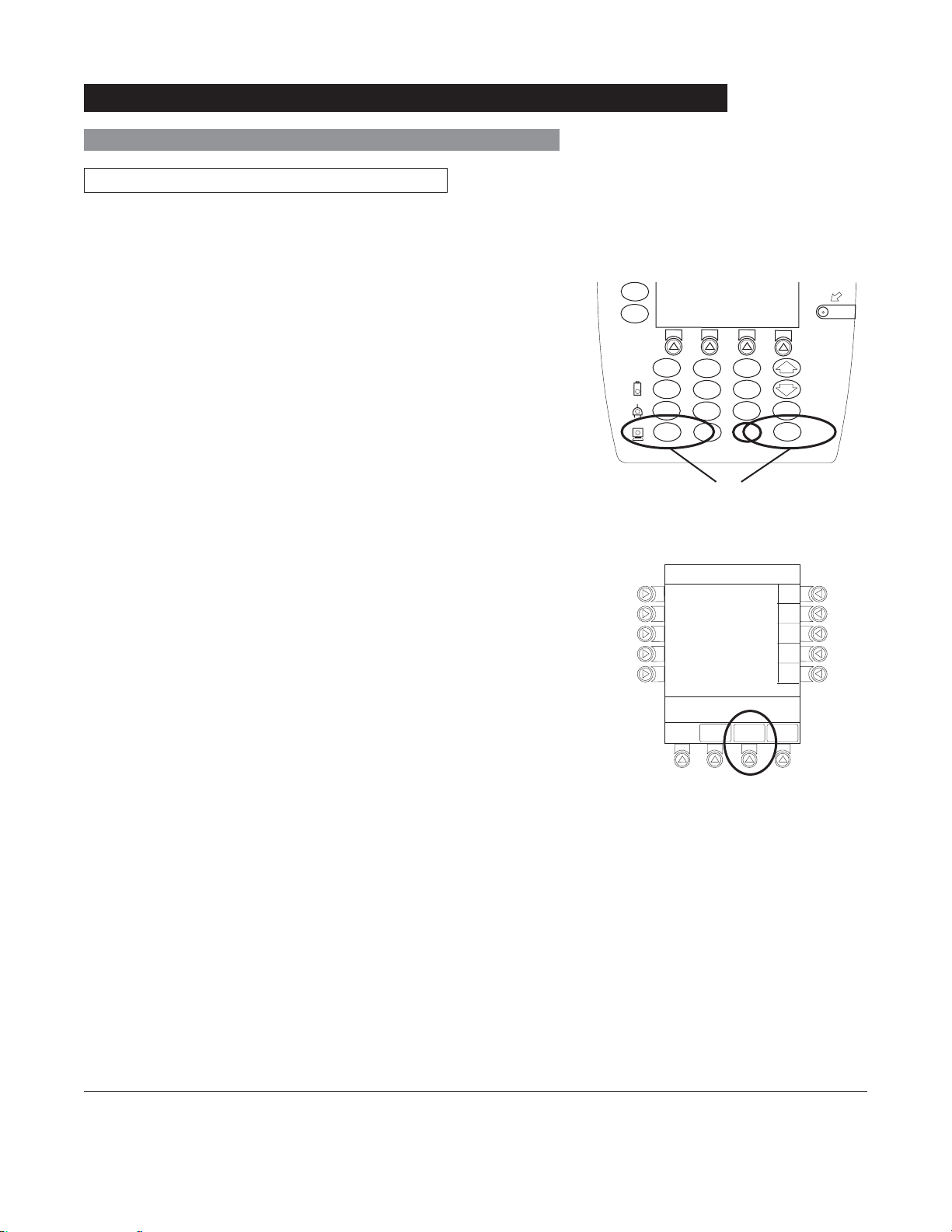
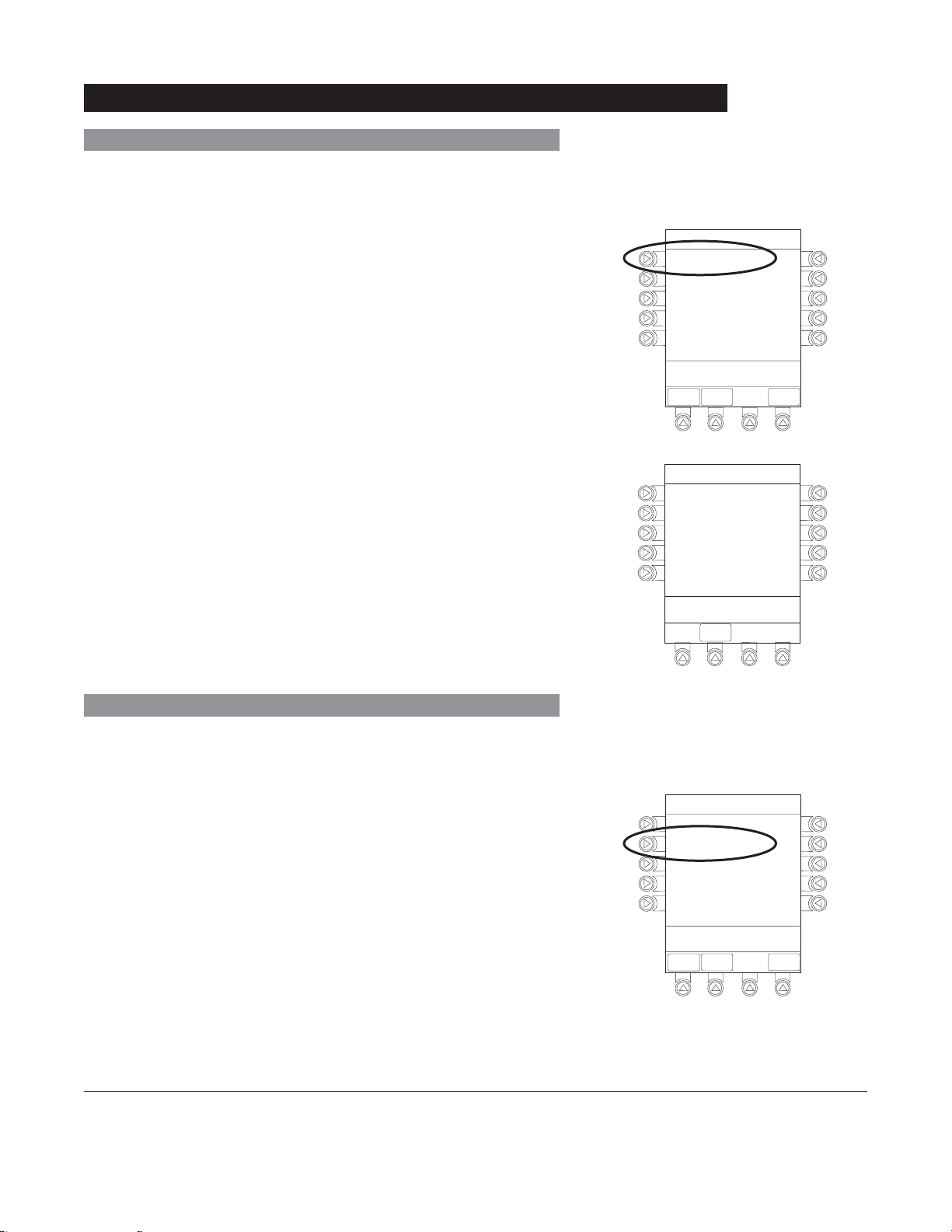
Power Off System
Press and hold CHANNEL OFF key until a beep is heard
(approximately
down.
1.5 seconds) and then release to initiate power
• During power off sequence, Main Display flashes
Powering Down.
• Once all attached modules are powered off, PC Unit
automatically powers down.
NOTE:
To interrupt the power down sequence, quickly press any key
(except SYSTEM ON) on the PC Unit.
System Options
Display Contrast
Powering Down
1. Press OPTIONS key.
2. Press Display Contrast soft key.
3. Adjust display and return to main screen (see "Start-Up",
"Adjusting Display Contrast" procedure).
SILENCE
OPTIONS
1
4
7
CLEAR
System Options 1 of 3
Display Contrast
Patient ID
Clinician ID
Power Down All Channels
Anesthesia Mode
>Select an Option or
EXIT
2
5
8
0
EXIT
SYSTEM
ON
3
6
ENTER
9
CANCEL
.
PAGE
DOWN
Alaris® System (with v9 Model 8000) DFU
PC Unit Section
General Setup and Operation 1-11
Page 22
Entering
1. Press OPTIONS key.
System Options (Continued)
Patient ID
2. Press Patient ID soft key.
3. Scan or manually enter patient identifier:
• To manually enter patient identifier, use numeric data
entry keys and/or alpha speed keys.
• To scan bar code on patient identification band, see
Auto-ID Module Section of this DFU.
4. To verify correct entry, press
CONFIRM soft key.
System Options 1 of 3
Display Contrast
Patient ID
Clinician ID
Power Down All Channels
Anesthesia Mode
>Select an Option or
EXIT
EXIT
Patient ID Entry
A
B
C
D
E
123456789CD_____
>Enter Patient ID and Press
CONFIRM
EXIT
CONFIRM
PAGE
DOWN
A-E
K-O
P-T
U-Y
PAGE
DOWN
F-J
1-1 2 General Setup and Operation
®
Alaris
System (with v9 Model 8000) DFU
PC Unit Section
Page 23
System Options (Continued)
Patient ID (Continued)
Modifying
1. Press OPTIONS key.
2. Press Patient ID soft key.
3. To clear entire entry, press
CLEAR key.
OR
To back up a single character at a time, press CANCEL
key.
4. To enter modified patient identifier, use numeric data entry
keys and/or alpha speed keys.
5. To verify correct entry, press CONFIRM soft key.
• New Patient ID Entry verification screen appears.
SILENCE
OPTIONS
1
4
7
CLEAR
Patient ID Entry
A
B
C
D
E
234567891EF_____
>Enter Patient ID and Press
CONFIRM
2
5
8
0
EXIT
OR
3
6
9
.
CONFIRM
ENTER
CANCEL
A-E
F-J
K-O
P-T
U-Y
PAGE
DOWN
SYSTEM
ON
Alaris® System (with v9 Model 8000) DFU
PC Unit Section
General Setup and Operation 1-13
Page 24
Patient ID (Continued)
Modifying (Continued)
System Options (Continued)
6. To accept modified Patient ID, press Yes soft key.
• Main screen appears with new Patient ID.
OR
To retain original (old) Patient ID, press No soft key.
• Main screen appears with old Patient ID.
NOTES:
An alphanumeric identifier, of up to 16 characters, can be
entered.
Press the soft key next to a letter group to list letters in that
group. Press the soft key next to an individual letter to enter
that letter.
To access the letter "Z" and special characters (hyphen,
underscore, space), press the PAGE DOWN soft key.
To clear an entire entry, press CLEAR key.
To back up a single character at a time, press CANCEL key.
Patient ID Entry
Patient ID
123456789CD
will be changed to
234567891EF
Is this correct?
>Press Yes or No
Yes
No
Clinician ID
1. Press OPTIONS key.
2. Press Clinician ID soft key.
1-14 General Setup and Operation
System Options 1 of 3
Display Contrast
Patient ID
Clinician ID
Power Down All Channels
Anesthesia Mode
>Select an Option or
EXIT
EXIT
®
Alaris
System (with v9 Model 8000) DFU
PC Unit Section
PAG E
DOWN
Page 25

System Options (Continued)
Clinician ID (Continued)
3. Scan or manually enter clinician identifier:
• To manually enter clinician identifier, use numeric data
entry keys and/or alpha speed keys.
4. To verify correct entry, press CONFIRM soft key.
NOTES:
An alphanumeric identifier, of up to 16 characters, can be
entered.
Press the soft key next to a letter group to list letters in that
group. Press the soft key next to an individual letter to enter
that letter.
To access the letter "
underscore, space), press the PAGE DOWN soft key.
To clear an entire entry, press CLEAR key.
To back up a single character at a time, press CANCEL key.
Z" and special characters (hyphen,
Clinician ID Entry
CONFIRM
A-E
F-J
K-O
P-T
U-Y
PAGE
DOWN
A
B
C
D
E
123456789CD_____
>Enter Clinician ID and Press
CONFIRM
EXIT
Power Down All Channels
1. Press OPTIONS key.
2. Press Power Down All Channels soft key.
Alaris® System (with v9 Model 8000) DFU
PC Unit Section
System Options 1 of 3
Display Contrast
Patient ID
Clinician ID
Power Down All Channels
Anesthesia Mode
>Select an Option or
EXIT
EXIT
PAG E
DOWN
General Setup and Operation 1-15
Page 26

System Options (Continued)
Power Down All Channels (Continued)
3. Press Yes soft key.
• During power off sequence, Main Display flashes
POWERING DOWN.
Anesthesia Mode
When the Anesthesia Mode is enabled while a module is
paused, the module remains in an indefinite pause until
restarted.
When Anesthesia Mode is enabled:
• All limits are set to Soft.
• Dose checking mode is set to Smart.
• Key-press audio is turned off.
• Tamper Resist Mode (panel locked) is not available.
®
• Guardrails
Software as anesthesia only. All Guardrails
profile can be viewed by pressing
drug list defaults to drugs designated by Editor
®
drugs in a
ALL DRUGS soft key.
System Options
Power Down
All Channels?
>Press Yes or No
Yes
No
CAUTION
When the Alaris® System is set up
for use in Anesthesia Mode, it is
important to select the profile that
corresponds with the care area the
patient will be taken to when the
Anesthesia Mode is discontinued.
®
This ensures that the Alaris
System
will be in the correct profile following
the use of the Anesthesia Mode.
• Bolus dose is automatically available for:
♦ Guardrails
♦ generic drug calculation setup
®
drugs that have bolus dose limits defined
• Anesthesia Mode, alternating with other required prompts,
displays in prompt bar of Main Display.
• Callback audio for paused module is permanently silenced.
• Review of drug calculation setup page is omitted when
restoring a stopped drug calculation.
• Clinical Advisories are not displayed.
• Auto-ID Module is not available.
1-16 General Setup and Operation
®
Alaris
System (with v9 Model 8000) DFU
PC Unit Section
Page 27
Anesthesia Mode (Continued)
Enabling
1. Press OPTIONS key.
System Options (Continued)
2. Press Anesthesia Mode soft key.
3. Press Enable soft key.
4. Press
CONFIRM soft key.
System Options 1 of 3
Display Contrast
Patient ID
Clinician ID
Power Down All Channels
Anesthesia Mode
>Select an Option or
EXIT
EXIT
System Options
Anesthesia Mode
Pump Module
Air Detection =
75
microliters
>Select an Option or Press
CONFIRM
CONFIRM
PAGE
DOWN
Enable
Disable
Change
Disabling
The Anesthesia Mode can be disabled, and normal operation
resumed, using either of the following three methods:
• System Options menu.
• Disconnecting from
AC power.
• Connecting to AC power.
Alaris® System (with v9 Model 8000) DFU
PC Unit Section
General Setup and Operation 1-1 7
Page 28
Anesthesia Mode (Continued)
Disabling (Continued)
From System Options Menu
System Options (Continued)
1. Press
OPTIONS key.
2. Press Anesthesia Mode soft key.
3. Press Disable soft key.
4. Press
CONFIRM soft key.
• Anesthesia Mode no longer appears on Main Display,
indicating it has been disabled.
Connecting To AC Power
1. Connect system to
AC power.
2. To continue using Anesthesia Mode, press Yes soft key.
OR
To discontinue Anesthesia Mode, press No soft key.
AC power cord was
connected.
Continue
>Select Yes or No
Yes
No
?ANESTHESIA MODE
Disconnecting from AC Power
1. Disconnect system from
AC.
• Anesthesia Mode is automatically disabled.
• All currently running infusions continue.
• A prompt appears as an alert that Anesthesia Mode
has been discontinued.
2. Press
CONFIRM soft key.
1-18 General Setup and Operation
Anesthesia mode was
when AC power
disconnected.
continue normal operation.
>Press CONFIRM
®
Alaris
System (with v9 Model 8000) DFU
discontinued
cord was
Press CONFIRM to
CONFIRM
PC Unit Section
Page 29
Battery Runtime
1. Press OPTIONS key.
System Options (Continued)
2. Press
PAGE DOWN soft key.
3. Press Battery Runtime soft key.
4. To return to main screen, press CANCEL key or EXIT soft
key.
System Options 2 of 3
Battery Runtime
System Configurations
Serial Numbers
Software Versions
Time of Day
>Select an Option or
EXIT
PAGE UP
EXIT
PAGE
DOWN
System Options
Estimated battery
runtime at current
operating parameters
9.5
hours
>Press CANCEL or EXIT
EXIT
System Configurations
1. Press OPTIONS key.
2. Press
PAGE DOWN soft key.
3. Press System Configurations soft key.
Alaris® System (with v9 Model 8000) DFU
PC Unit Section
System Options 2 of 3
Battery Runtime
System Configurations
Serial Numbers
Software Versions
Time of Day
>Select an Option or
EXIT
PAGE UP
EXIT
PAGE
DOWN
General Setup and Operation 1-19
Page 30

System Options (Continued)
System Configurations (Continued)
4. Press PC Unit soft key.
5. To review various system configuration settings, press
PAGE DOWN and PAGE UP soft keys.
System Configuration - Module
Factory Default:
Shared Infusion Settings
PC Unit
Pump Module
SPO2 Module
>Press CANCEL or EXIT
EXIT
System Config - PCU 1 of 3
Alarm audio:
Anesthesia Mode: Disabled
Battery meter:
Clock setup:
Limit Checking:
>Press CANCEL or EXIT
EXIT
Yes
PAGE
DOWN
Profile 1
Disabled
09:00
ALWAYS
PAGE
DOWN
System Config - PCU 2 of 3
Key click audio:
Max Pt. BSA:
Max Pt. weight:
Patient ID Entry:
Pending IV Orders:
>Press CANCEL or EXIT
PAGE
EXIT
UP
Enabled
2
2m
500 kg
Disabled
Enabled
DOWN
PAGE
1-20 General Setup and Operation
®
Alaris
System (with v9 Model 8000) DFU
PC Unit Section
Page 31

System Options (Continued)
System Configurations (Continued)
6. To return to main screen, press CANCEL key or EXIT soft
key.
NOTES:
The Profiles option is listed only if it is disabled.
The Limit Checking (or Dose Checking), Max Pt. BSA,
and Pending IV orders options are listed only if the Profiles
option is enabled and a valid Data Set is loaded.
Serial Numbers
1. Press OPTIONS key.
2. Press
PAGE DOWN soft key.
3. Press Serial Numbers soft key.
• Serial numbers for PC Unit and all attached modules
display .
System Config - PCU 3 of 3
PM Reminder:
Tamper resist:
>Press CANCEL or EXIT
PAGE
EXIT
UP
System Options 2 of 3
Battery Runtime
System Configurations
Serial Numbers
Software Versions
Time of Day
Disabled
Disabled
4. To return to main screen, press EXIT soft key.
NOTE:
"nnnn-nnnnnnnn" in the illustrated display represents a serial
number.
Alaris® System (with v9 Model 8000) DFU
PC Unit Section
>Select an Option or
EXIT
PAGE UP
EXIT
PAGE
DOWN
Serial Number Review
PC Unit:
Module A:
Module B:
Module C:
Module D:
>Press CANCEL or EXIT
nnnn-nnnnnnnn
nnnn-nnnnnnnn
nnnn-nnnnnnnn
nnnn-nnnnnnnn
nnnn-nnnnnnnn
EXIT
General Setup and Operation 1-21
Page 32

Software Versions
1. Press OPTIONS key.
System Options (Continued)
2. Press
PAGE DOWN soft key.
3. Press Software Versions soft key.
4. To review software version information, press View soft
key next to applicable module.
OR
To return to main screen, press EXIT soft key.
System Options 2 of 3
Battery Runtime
System Configurations
Serial Numbers
Software Versions
Time of Day
>Select an Option or
EXIT
PAGE UP
EXIT
Software Rev. Review
PC Unit:
Module A:
Module B:
Module C:
Module D:
>Select an Option or
EXIT
EXIT
PAGE
DOWN
View
View
View
View
View
OR
5. To return to previous screen, press EXIT soft key.
NOTE:
"nn.nn" in the illustrated display represents a software
version.
1-22 General Setup and Operation
®
Alaris
System (with v9 Model 8000) DFU
Software Rev. Review
Module Software: A
Main processor:
Main boot block:
Keyboard:
>Press CANCEL or EXIT
EXIT
nn.nn
nn.nn
nn.nn
PC Unit Section
Page 33

System Options (Continued)
Time of Day
1. Press OPTIONS key.
2. Press
PAGE DOWN soft key.
3. Press Time of Day soft key.
4. If time is correct, press CONFIRM soft key.
OR
To change time, press Change Time soft key.
System Options 2 of 3
Battery Runtime
System Configurations
Serial Numbers
Software Versions
Time of Day
>Select an Option or
EXIT
PAGE UP
EXIT
PAGE
DOWN
System Options
Time of Day
Current time:
09:00
Change
Time
5. Enter current Time of Day.
>CONFIRM Time-of-Day
CONFIRM
EXIT
System Options
Time of Day
Current time:
__:__
>Enter Current Time
EXIT
CONFIRM
Change
Time
Alaris® System (with v9 Model 8000) DFU
PC Unit Section
General Setup and Operation 1-23
Page 34

System Options (Continued)
Time of Day (Continued)
6. Press CONFIRM soft key.
NOTE:
The format is a
24-hour clock (military time).
Network Status
This option is available only when the Communications
Interface Board Accessory is installed and the PC Unit has
been flashed to support wireless communications with Alaris
Server or Mobile Systems Manager. The displayed status
updates immediately when a status change takes place.
System Options
Time of Day
Current time:
14:30
>Press CONFIRM
EXIT
®
CONFIRM
Change
Time
1. Press
OPTIONS key.
2. Press PAGE DOWN soft key 2 times.
3. To view network status and wireless status information,
press Network Status soft key.
System Options 3 of 3
Network Status
Wireless Connection
Data Set Status
Maintenance Due Yes
>Select an Option or
EXIT
EXIT
PAGE UP
1-24 General Setup and Operation
®
Alaris
System (with v9 Model 8000) DFU
PC Unit Section
Page 35

System Options (Continued)
Network Status (Continued)
4. Enter password (can be found in System Maintenance
software instructions).
• Information based on a wireless status of
DISASSOCIATED, SCANNING, IDENTIFYING,
ASSOCIATING, or ASSOCIATED is displayed.
• If wireless status is
ASSOCIATED, wireless connectivity
link quality and signal strength is identified.
5. To view network connectivity information, press NET
STATUS
• A status of
soft key.
DISABLED, DISCONNECTED,
CONFIGURING, or CONNECTED is displayed.
System Options
Viewing Network Status
is only to be used by
qualified personnel.
*____
>Enter Password or
EXIT
CONFIRM
EXIT
System Options
Wireless Status
ASSOCIATED
Status :
AM SWEPXXXXXXXX
SSID :
XXXXXXXXXXXXXXX
BSSID :
00:0A:B3:36:9F:88
Channel :
1 (2.142 Ghz)
Authentication :
Encryption:
Speed: 11 Mbps
>Press CANCEL to Exit
OPEN
40 bit WEP
Link Quality
Signal Strength
NET
STATUS
NET
ADDRESS
35%
75%
SERVER
STATUS
6. To view network address information, press
ADDRESS soft key.
NET
System Options
Network Status
Status :
Uptime :
Bytes Sent:
Bytes Recv:
>Press CANCEL to Exit
WIRELESS
STATUS
CONNECTED
03:45:35
13, 890
1,200,150
NET
ADDRESS
SERVER
STATUS
Alaris® System (with v9 Model 8000) DFU
PC Unit Section
General Setup and Operation 1-25
Page 36

System Options (Continued)
Network Status (Continued)
7. To view server connectivity information, press SERVER
STATUS soft key.
• Information based on a status of
SEARCHING, VERIFYING, CONNECTING, or
CONNECTED is displayed.
DISABLED,
System Options
Network Address
MAC Address:
DHCP Enabled :
IP Address:
Subnet Mask:
Gateway:
DNS Primary:
DNS Secondary:
00:0A:B3:36:9F:88
YES
192.168.0.55
255.255.255.0
192.168.0.1
192.168.0.1
192.168.0.3
>Press CANCEL to Exit
NET
WIRELESS
STATUS
STATUS
System Options
Server Status
Status:
Uptime:
Server Address:
TCP Port:
Local Timeout:
Server Timeout:
Encryption:
Bytes Sent:
Bytes Received:
Last Disconnect:
>Press CANCEL to Exit
WIRELESS
STATUS
CONNECTED
00:00:02
192.168.0.2
65535
3612 / 4000ms
20ms
AES 128-bit
1,103,470,776
94,300
UNKNOWN
Beacons Received
NET
ADDRESS
STATUS
NET
SERVER
STATUS
20%
Wireless Connection
This option is available only when the Communications
Interface Board Accessory is installed and the PC Unit has
been flashed to support wireless communications with Alaris
Server or Mobile Systems Manager.
1. Press
2. Press
OPTIONS key.
PAGE DOWN soft key 2 times.
3. Press Wireless Connection soft key.
®
System Options 3 of 3
Network Status
Wireless Connection
Data Set Status
Maintenance Due Yes
>Select an Option or
EXIT
EXIT
PAGE UP
1-26 General Setup and Operation
®
Alaris
System (with v9 Model 8000) DFU
PC Unit Section
Page 37

System Options (Continued)
Wireless Connection (Continued)
4. To disable wireless communication, press Disable soft
key.
OR
To enable wireless communication, press Enable soft key.
Data Set Status
1. Press OPTIONS key.
2. Press
PAGE DOWN soft key 2 times.
WARNING
To comply with FAA regulations and
prevent potential interference with
aircraft communications, disable
wireless communication when the
®
Alaris
System is used in an aircraft.
System Options
Wireless
Connection
>Press ENABLE or
DISABLE
Enable
Disable
3. To view Data Set status, press Data Set Status soft key.
-- Continued Next Page --
Alaris® System (with v9 Model 8000) DFU
PC Unit Section
System Options 3 of 3
Network Status
Wireless Connection
Data Set Status
Maintenance Due Yes
>Select an Option or
EXIT
EXIT
PAGE UP
General Setup and Operation 1-27
Page 38

System Options (Continued)
ID: 83442BB
Activated:
2005-09-18 08:45
Data Set Status (Continued)
• A status of Current, Pending, Transferring, or Not
Activated displays.
Maintenance Due
1. Press OPTIONS key.
2. Press
PAGE DOWN soft key 2 times.
3. Press Maintenance Due soft key.
System Options
Data Set Status
B
Current:
(none available)
ID: 83442BB
Activated: 2005-09-18 08:45
Midtown Hospital
Pending:
Dataset ID: 83442BB
Not Activated
>Press EXIT
EXIT
System Options 3 of 3
Network Status
Wireless Connection
Data Set Status
Maintenance Due Yes
4. To return to main screen, press EXIT soft key.
-- Continued Next Page --
1-28 General Setup and Operation
>Select an Option or
EXIT
EXIT
PAGE UP
®
Alaris
System (with v9 Model 8000) DFU
System Options
Maintenance Due Dates
Module(s) due for routine
B
preventative maintenance:
PC Unit:
.
Module A:
Module B:
Module C:
Module D:
>Press CANCEL or EXIT
YYYY-MM-DD
YYYY-MM-DD
YYYY-MM-DD
YYYY-MM-DD
YYYY-MM-DD
EXIT
PAGE
DOWN
PC Unit Section
Page 39

System Options (Continued)
Maintenance Due (Continued)
NOTE:
PAGE DOWN soft key appears only if an Auto-ID Module is
attached.
System Options
Maintenance Due Dates
Module(s) due for routine
B
preventative maintenance:
Bar Code:
.
Bar Code:
(Hand held)
>Press CANCEL or EXIT
PAGE UP
YYYY-MM-DD
YYYY-MM-DD
EXIT
Alaris® System (with v9 Model 8000) DFU
PC Unit Section
General Setup and Operation 1-29
Page 40

THIS PAGE
INTENTIONALLY
LEFT BLANK
1-30 General Setup and Operation
®
Alaris
System (with v9 Model 8000) DFU
PC Unit Section
Page 41

Warnings and Cautions
DANGER
Explosion risk if used in the presence of flammable
anesthetic agents or gasses.
General
WARNINGS
• Assess patient’s condition before silencing an alarm. Do
not silence alarm if patient safety might be compromised.
• Before each use, verify the alarm limits are appropriate
for the patient.
®
• The Alaris
up. The PC Unit should beep, no errors should occur, and
if a module is connected, all
the Alaris
PC Unit or module from use.
System performs a self check during power
®
System fails the self check, remove the failing
LED segments should flash. If
General Information
• When properly secured/snapped, the release latch
provides a very secure connection between modules. If
not properly latched, a module can be dislodged during
operation.
• Disconnect from main (
AC) and battery power when
performing maintenance.
• Electrical shock hazard. Do not open case. Refer to
qualified service personnel.
• To comply with
FAA regulations and prevent potential
interference with aircraft communications, disable
®
wireless communication when the Alaris
System
is used in an aircraft (see "System Options", "Network
Status").
®
• The Alaris
System is not intended to replace supervision
by medical personnel. The user must become thoroughly
®
familiar with the Alaris
System features, operation and
accessories prior to use.
• Always use a grounded, three-wire receptacle. Where
the integrity of the protective earth grounding system is in
doubt, operate on internal battery.
Alaris® System (with v9 Model 8000) DFU
PC Unit Section
General Information 1-31
Page 42

Warnings and Cautions (Continued)
General (Continued)
CAUTIONS
• Hyperbaric Chamber Operation:
♦ The Alaris
enriched environments.
♦ The Alaris
EtCO
malfunction alarms due to the hyperbaric chamber
environment or unintentional key presses when used in
a hyperbaric chamber.
♦ The healthcare facility's hyperbaric safety director is
responsible for all equipment used in the hyperbaric
chamber environment.
• Should an instrument or accessory be dropped or
severely jarred, it should be immediately taken out of use
and inspected by qualified service personnel, to ensure its
proper function prior to reuse.
• If an instrument appears damaged, contact Cardinal
Health for authorization to return it for repair.
®
System is not certifi ed for use in oxygen-
®
System, with the exclusion of the
Module, has been verifi ed to operate with no
2
Electromagnetic Compatibility
WARNINGS
• Do not use the Alaris® System near Magnetic Resonance
Imaging (
• Do not use the Alaris
MRI), including Stereotaxis technology.
®
System near Therapeutic Radiation
equipment, such as Linear Accelerators.
• Use of any accessory, transducer or cable other than
those specified may result in increased emissions or
decreased Alaris
®
System immunity.
CAUTIONS
• The Alaris® System should not be used adjacent to or
stacked with other equipment. If adjacent or stacked
use is necessary, monitor the Alaris
®
System to verify it is
operating normally in that setup.
• Portable and mobile
RF communications can affect
medical electrical equipment.
1-32 General Information
®
Alaris
System (with v9 Model 8000) DFU
PC Unit Section
Page 43

Warnings and Cautions (Continued)
Electromagnetic Compatibility (Continued)
CAUTIONS
• Interconnected data communications systems must
be certified to
IEC 60601–1 (electromedical equipment).
• The Alaris
professionals only. This is a
medical system. In a domestic environment, this system
may cause radio interference. Reorienting, relocating
or shielding the system, or filtering the connection to the
public mains network, are examples of steps that can be
taken to reduce or eliminate interference.
• Medical electrical equipment needs special precautions
regarding
according to the
"Appendix" Section of this DFU (see "Regulations and
Standards", "Compliance").
IEC 60950 (data processing equipment) or
®
System is intended for use by healthcare
CISPR 11 Class B Group 2
EMC and needs to be installed and used
EMC information provided in the
• Nurse call systems must be certified to
UL 1069 (hospital
signaling and nurse call equipment) or comply with the
requirements specified in
IEC 60601–1.
Features and Displays
Features and Definitions
See the product-specific Section of this DFU that applies to the attached module(s) for features and
definitions specific to that module.
Clinician ID An optional alphanumeric
entered and displayed.
Data Set Created using Editor Software authoring tool and then transferred
to PC Unit. A Data Set reflects facility’s best-practice guidelines for
IV Drug administration and includes: Profile Drug Libraries, Clinical
Advisories, instrument configurations, and Channel Label Libraries.
16-character clinician identifier that can be
Alaris® System (with v9 Model 8000) DFU
PC Unit Section
General Information 1-33
Page 44

Features and Displays (Continued)
Features and Definitions (Continued)
Guardrails® Suite MX Designed to help prevent programming errors by:
• Customizing device configurable settings to meet need of selected
hospital/facility area/unit (profile).
• Comparing user programming with hospital-defined best-practice
guidelines.
• Providing a visual and audio prompt if an out-of-limits entry is
made.
Patient ID An optional alphanumeric
16-character patient identifier that can be
entered and displayed.
• When enabled,
• When disabled,
ID entry defaults to Startup screen.
ID entry is only accessible from System Options
screen.
Profile A unique set of system configuration settings and best-practice
guidelines for a specific patient population or patient type, and can
consist of following components:
• Instrument configuration settings.
• A Drug Library, which includes Drug names, standard
concentrations, dosing units, duration limits, and optional
associated Clinical Advisories for both continuous and bolus dose
infusion.
• An
IV Fluid library, an optional library consisting of IV Fluids (for
example, TPN) and limits around rate of delivery.
• A Channel Label Library with text (alphanumeric) labels, which
allows identification (on modules) that can be used to indicate
route of delivery (for example, epidural).
Profile settings are established by the facility’s own multi-disciplinary
team prior to system implementation. Profile parameters are used to
create a Data Set, which is then transferred to the PC Unit.
System Configuration Allow system settings to be customized. If Profiles feature
is enabled, system settings defined for selected profile are
automatically activated.
Tamper Resist Provides a quick one-touch lockout of front panel keypad.
1-34 General Information
®
Alaris
System (with v9 Model 8000) DFU
PC Unit Section
Page 45

Features and Displays (Continued)
Operating Features, Controls, Indicators
IUI Connector, Left
Main Display
Soft Keys: When pressed,
allows selection of options or
infusion parameters appearing
on Main Display adjacent to
soft key.
Silence Key: When pressed
during an alarm, silences audio
for 2 minutes.
Options Key: When pressed,
allows access to available
System or Channel Options.
Soft Keys (see above)
(not visible)
SYSTEM
ON
IUI Connector, Right
System On Key: When
pressed, changes Alaris
from Standby to Operating mode.
®
System
Up/Down Arrows: When
pressed, increases or decreases
parameter with each key press
or scrolls up and down when
pressed and held.
Battery Indicator: When
illuminated, indicates Alaris®
System is operating on battery
power.
Power Indicator: When
illuminated, indicates Alaris®
System is connected to an AC
power source.
Wireless Network
Indicator: When illuminated,
indicates Alaris® System is
connected to Alaris® Server
or Mobile Systems Manager.
When blinking, indicates data
transfer.
Clear Key: When
pressed, clears current
selected parameter setting
to "0".
Module Release Latch:
When pressed, allows
module to be removed.
Enter Key: When pressed,
confirms current parameter entry.
Cancel Key: When pressed,
sequentially backs out of current
setup sequence.
Decimal Key: When pressed,
inserts a decimal point in numeric
data.
Numeric Keypad
Alaris® System (with v9 Model 8000) DFU
PC Unit Section
General Information 1-35
Page 46

Features and Displays (Continued)
Operating Features, Controls, Indicators (Continued)
IUI Connector, Right IUI Connector, Left
Power Cord Strap
Use this bolt to reorient
Pole Clamp 90° for
attachment to a bed rail
instead of a pole.
Primary Audio Speaker
Connector Plug over RJ45
Communication Data Port
Tamper Resist Switch
Option Upgrade Panel
1-36 General Information
®
Alaris
System (with v9 Model 8000) DFU
PC Unit Section
Page 47

Features and Displays (Continued)
Displays
The displays illustrated throughout this document are for
illustration purposes only. The display content varies,
depending on configuration settings, hospital-defined Data
Set uploaded using the Guardrails
variables.
Main Display
®
Suite MX, and many other
Title Bar
Module Status
• A solid letter display indicates
module is operating.
• An outlined letter display
indicates module is attached
and ready for use.
Soft Keys
Module Selected Indicator
"Inactive" Soft Key
Nonhighlighted indicates a
nonselected soft key.
"Active" Soft Key
Highlighted indicates a
selected soft key.
Prompt Bar
Look here for user prompts.
Midtown Hospital
Adult ICU
VTBI = 250.0 mL
VOLUME
INFUSED
Infusion Setup
RATE
VTBI
>Press START
PAUSE
40 mL/h
_250 mL
AUDIO
ADJUST
SECOND-
ARY
START
SYSTEM
ON
SYSTEM
ON
Alaris® System (with v9 Model 8000) DFU
PC Unit Section
General Information 1-37
Page 48

System Configurable Settings
If the configuration settings need to be changed from the
Factory default settings, reference the applicable Technical
Service Manual or contact Cardinal Health Technical Support,
for technical, troubleshooting, and preventive maintenance
information.
With the Profiles feature enabled, the settings are configured
independently for each profile. A hospital-defined, bestpractice Data Set must be uploaded to enable the Profiles
feature. Date and Time is a system setting and is the same in
all profiles.
Feature
Alarm Audio
Anesthesia Mode
Battery Meter
Clock Setup (
Dose Checking
Key Click Audio
Max Patient Weight
Patient ID Entry
PM Reminder
Preventive Maintenance)
(
Profiles
Tamper Resist
Date and Time)
Default Setting Options
Profile 1
Disabled
Disabled
N/A
Always
Enabled
500 kg
Disabled
Enabled
Disabled
Disabled
Profile 1, 2 or 3
Enabled - Disabled
Enabled - Disabled
Set date and time
Always, Smart
Enabled - Disabled
0.1 - 500 kg
Enabled - Disabled
Enabled - Disabled
Enabled - Disabled
Enabled - Disabled
1-38 General Information
®
Alaris
System (with v9 Model 8000) DFU
PC Unit Section
Page 49

Specifications and Symbols
Specifications
Battery Operation: Battery run time is a function of the number of modules attached and module
activity. With a new, fully charged battery, the system operates as follows before
a "BATTERY DISCHARGED" message occurs:
• 6 hours with 1 Pump Module infusing at 25 mL/h
• 6 hours with 1 Pump Module infusing at 25 mL/h and 1 Auto-ID Module
• 3 hours with 4 Pump Modules infusing at 25 mL/h
• 3 hours with 4 Pump Modules infusing at 25 mL/h and 1 Auto-ID Module
• 4.5 hours with 1 active SpO2 Module
• 6 hours with 1 Syringe Module or PCA Module infusing at 5 mL/h
• 3 hours with 4 Syringe Modules, or 1 PCA Module and 3 Syringe Modules,
infusing at 5 mL/h
• 4 hours with 1 active EtCO2 Module
Communication Data Port: RS-232 with an RJ45 connector.
Dimensions:
Electric Classification: Class 1, Internally Powered Equipment
6.9" W x 8.8" H x 9" D (including pole clamp)
Electronic Memory: System configuration parameters stored in volatile memory are retained for at
least 6 months by internal backup lithium battery. Module-specific parameters are
stored for 8 hours when system is turned off. After 8 hours of continuous off-time,
or if a module is detached, module-specific trend data (if applicable) and modulespecific operating parameters are automatically purged. If a PCA, SpO2 or EtCO2
Module is detached and replaced with another PCA, SpO2 or EtCO2 Module, its
module-specific trend data is purged.
Environmental Conditions: Operating Storage/Transport
Temperature Range: 41 - 104° F -4 - 140° F
(5 - 40° C) (-20 - 60° C)
Relative Humidity: 20 - 90% 5 - 85%
(Avoid prolonged exposure
to relative humidity >85%)
Noncondensing Noncondensing
Atmospheric Pressure: 525 - 4560 mmHg 375 - 760 mmHg
(700 - 6080 hPa) (500 - 1013 hPa)
Equipment Orientation: To ensure proper operation, Alaris® System must remain in an upright position.
Fluid Ingress Protection: IPX1, Drip Proof
Mode of Operation: Continuous
Power Requirements: 100 - 240V ~, 50/60 Hz, 150 VA MAX
Shock Protection: Type CF, Defibrillator Proof
Weight: 7.2 lbs
Alaris® System (with v9 Model 8000) DFU
PC Unit Section
General Information 1-39
Page 50

Specifications and Symbols (Continued)
Specifications (Continued)
NOTES:
See the product-specific Section of this DFU for shock protection type and defibrillation-proof rating
information.
Power Cords:
North America: To ensure correct polarity and grounding reliability, use power cords that incorporate a
NEMA 5-15P (125V) or NEMA 6-15P (250V) plug only.
International: Use only cords that comply with IEC 60245, or IEC 60227, designation #53 and local electrical
codes and/or regulations.
Symbols
See the product-specific Section of this DFU that applies to the attached module(s) for symbols specific
to that module.
Silenced alarm.
Alternating Current: Indicates device should be attached to alternating current source,
50/60 Hz only.
Battery power.
!
+
75
Caution: Reference accompanying documentation.
Canadian and
U.S. Certification Mark: Products bearing this mark have been tested
and certified in accordance with applicable U.S. and Canadian electrical safety and
performance standards.
Communications connector for
RS-232 attachment.
Consult operating instructions.
Type
CF defibrillation-proof equipment.
Electrostatic discharge (ESD).
1-40 General Information
®
Alaris
System (with v9 Model 8000) DFU
PC Unit Section
Page 51

Specifications and Symbols (Continued)
Symbols (Continued)
Fuse Replacement: Replace fuse only with same type and rating.
IPX1
MM-YYYY
nly
O
Protection against fluid ingress: Drip Proof
IUI Connector: Inter-Unit Interface connector used to establish power and
communications between PC Unit and attached modules.
Main Power: Connected to alternating current,
100-240 VAC.
Manufacturing Date: Number adjacent to symbol indicates month and year of
manufacture.
Potential Equalization Conductor (if so equipped). Note: If integrity of
PEC or Hospital
Earth System is in question, operate instrument using internal battery power.
Radio frequency (
Caution: Federal (
SYSTEM ON"
"
RF) transmission.
U.S.A.) law restricts this device to sale by or on order of a physician.
Tamper Resist activate/deactivate switch.
Alaris® System (with v9 Model 8000) DFU
PC Unit Section
General Information 1-41
Page 52

THIS PAGE
INTENTIONALLY
LEFT BLANK
1-42 General Information
®
Alaris
System (with v9 Model 8000) DFU
PC Unit Section
Page 53

Troubleshoot ing and M aint enanc e
General
The Alaris® System Technical Service Manual is available
from Cardinal Health. It includes routine service schedules,
interconnect diagrams, component parts lists and descriptions,
test procedures, and other technical information, to assist
qualified service personnel in repair and maintenance of the
instrument’s repairable components. Maintenance procedures
are intended to be performed only by qualified personnel,
using the Service Manual and System Maintenance software.
Alarms, Errors, Messages
To enhance safety and ease of operation, the Alaris® System
provides a full range of audio and visual alarms, errors, and
messages.
Operating the system near equipment which radiates highenergy radio frequencies (such as, electrosurgical/cauterizing
equipment, portable radios, cellular telephones) may cause
false alarm conditions. If this happens, reposition the Alaris
System away from the source of interference or turn off the
system and manually regulate the flow with the clamp and/or
monitor the vital parameters using an appropriate clinical
alternative
®
Definitions
See the product-specific Section of this DFU that applies to the attached module(s) for alarm, error and
message definitions specific to that module.
Advisory / Message A sequence of audio and/or visual signals indicating operating status of
®
Alaris
System.
Alarm An audio and visual signal that a potentially unsafe condition is
present. Immediate action is required.
Alarm Silence Alarms can be silenced for up to
120 seconds by pressing SILENCE
key. Alarm indicators remain on and, if applicable, alarm silence
symbol (see monitoring module Section of this DFU) is displayed.
Silence period can be ended by pressing
Alaris® System (with v9 Model 8000) DFU
PC Unit Section
Troubleshooting and Maintenance 1-43
CANCEL SILENCE soft key.
Page 54

Alarms, Errors, Messages (Continued)
Definitions (Continued)
Error An audio and/or visual signal that a failure has been detected.
Immediate action is required.
Maintenance Reminder A visual message that, when enabled, appears at module startup when
scheduled preventive maintenance is due/overdue for any part of
®
Alaris
Prompt An audio signal and/or a visual message appearing on bottom line of
Main Display or in Message Display. Audio signal may be silenced for
12 seconds by pressing SILENCE key.
Audio Characteristics
The Alaris® System provides various types of alert information. See the product-specific Section of this
DFU that applies to the attached module(s) for audio characteristics specific to that module.
Type Sound Notes
System (PC Unit or attached module).
Advisory / Message
Alarm
Error (Hardware Detected)
Error (Software Detected)
Illegal Key Press
Key Click
Prompt
One short beep every 2 seconds
Choice of
selectable in System Configuration
Pairs of long beeps
Pairs of long beeps
Two short beeps
One short beep
One short beep every
3 alarm audio profiles,
2 seconds
Variable volume; can be silenced
2 minutes.
for
Variable volume; can be silenced
for 2 minutes.
Fixed maximum decibel volume;
cannot be silenced.
Fixed maximum decibel volume;
can be silenced for 2 minutes.
Variable volume; cannot be
silenced.
Fixed minimum volume; can be
silenced and disabled in System
Configuration.
Variable volume; can be silenced.
1-44 Troubleshooting and Maintenance
®
Alaris
System (with v9 Model 8000) DFU
PC Unit Section
Page 55

Alarms, Errors, Messages (Continued)
Alarms
Alarm Meaning Response
Battery Discharged
Channel Disconnected
Very Low Battery <5 minutes to
system shutdown
Error Meaning Response
Errors
Operation of all modules stopped
due to insufficient battery charge.
Module(s) disconnected while in
operation or have a communication
problem.
Battery has
of power at current power
consumption rate before operation
stops.
5 minutes or less
Connect AC power cord to power
source (alarm silenced). To
continue operation of paused
modules, press
affected module.
To silence alarm and clear
message from screen, press
CONFIRM soft key. Reattach
module, if needed, ensuring it is
securely "clicked" into place at
Module Release Latch. If alarm is
still present, replace module with
an operational instrument.
Connect
source (alarm silenced).
AC power cord to power
RESTART key on
Audio System Error
Channel Error
Defective Battery
Alaris® System (with v9 Model 8000) DFU
PC Unit Section
Main speaker failure.
Error detected. Operation stops on
affected module.
Defective battery.
1. Visually check alarm status to
determine whether or not an
operational alarm also needs to
be addressed (red Alarm Status
Indicator lit).
2. Replace PC Unit with an
operational instrument.
To silence alarm and continue
operation of unaffected modules,
press CONFIRM soft key. Replace
module with an operational
instrument.
To continue temporary operation,
press SILENCE key. Replace
PC Unit with an operational
instrument.
Troubleshooting and Maintenance 1-45
Page 56

Alarms, Errors, Messages (Continued)
Errors (Continued)
Error Meaning Response
Hardware Detected Error
Missing Battery
Power Supply Error
System Error
Message Meaning Response
Battery Run Time = X.X hours
Messages
Error detected on PC Unit.
Operation stops on all modules.
Battery not present or not
connected.
Power supply system malfunction.
Error detected on PC Unit.
Operation continues on all attached
modules.
AC power cord is disconnected
from power source. Approximate
remaining battery run time under
current power consumption rate is
displayed.
Replace PC Unit with an
operational instrument.
To continue temporary operation,
press SILENCE key. Replace
PC Unit with an operational
instrument.
Disconnect AC power immediately.
To continue operation under
battery power, press SILENCE
key. Replace PC Unit with an
operational instrument.
To continue temporary operation,
press SILENCE key. Replace
PC Unit with an operational
instrument.
Connect AC power cord to power
source as soon as possible.
Low Battery
Panel Locked
Panel Unlocked
Powering Down
1-46 Troubleshooting and Maintenance
Low battery threshold sensed;
remaining battery run time is
limited.
Tamper Resist feature is active and
key was pressed.
Tamper Resist feature deactivated.
Last module powering off. System
shuts off in indicated number of
seconds.
Alaris
Connect AC power cord to power
source (alarm silenced).
If appropriate, deactivate Tamper
Resist feature using Tamper Resist
Control on back of PC Unit.
None.
Press any key, except SYSTEM
key, to cancel power down
ON
sequence.
®
System (with v9 Model 8000) DFU
PC Unit Section
Page 57

Alarms, Errors, Messages (Continued)
Messages (Continued)
Message Meaning Response
Replace Battery Occurs at System On. Battery has
less than 50% of original capacity.
Storage
Plug the PC Unit into an AC outlet during storage to ensure a
fully charged battery. The
AC indicator light ( ) is on when the
PC Unit is plugged in.
Battery Care and Maintenance
Battery Type and Charging
The PC Unit is equipped with a 12 volt, 4000 mAh nickel
metal hydride battery. The battery is charging whenever
the instrument is plugged into an
expectancy of the battery is dependent on the amount of
use, the depth of discharge, and the state of the charge that
is maintained. Generally, the battery has the longest life if
the instrument is plugged in and battery use is infrequent.
Frequent use of battery power and insufficient battery charge
cycles significantly decrease the life of the battery.
AC receptacle. The life
To continue normal operation
with reduced battery capacity,
press CONFIRM soft key. Replace
PC Unit with an operational
instrument.
The quality of the battery is also a significant factor in
determining battery life and runtime. The battery cannot be
repaired and should not be opened. Replace the battery with
the same type, size and voltage rating. Use of any other brand
may yield poor performance and is not recommended.
Batteries should be charged in a room with a temperature
between
50 - 80.6° F (10 - 27° C), to minimize charge time and
maximize battery life.
Alaris® System (with v9 Model 8000) DFU
PC Unit Section
Troubleshooting and Maintenance 1-47
Page 58

Battery Care and Maintenance (Continued)
Battery Charge
• The PC Unit is shipped with the battery in a discharged
condition.
• Before the PC Unit is released for use, it should be plugged
into a hospital grade
at least
8 hours. This ensures proper battery operation
when the Alaris
• Whenever possible, leave the power cord connected to an
external
AC power source while operating the instrument.
AC outlet and the battery charged for
®
System is first set up for patient use.
Battery Care
The battery capacity should be checked at least once every
6 months. Reference the Alaris
®
System Technical Service
Manual for test and replacement procedures.
If the PC Unit is to be stored at temperatures in excess of
30° C) for 1 or more months, the battery should be removed
(
and placed in an environment of
If the batteries are to be stored for more than
50 - 86° F (10 - 30° C).
1 year, they
86° F
should be charged at least once per year to prevent leakage
and deterioration in performance due to self-discharge.
When the battery is first being put into use, or has been out of
use for
1 or more months, it will not have full capacity due to
deactivation of reactants.
Restore such batteries to original performance by repeating
1 or 2 cycles of fully charging and fully discharging.
Some temporary reduction in capacity might become apparent
if the battery is partially discharged repeatedly. Doing
2 cycles of full discharge and full charge can restore full
or
1
performance.
Battery Cautions and Disposal
Battery replacement should be performed by qualified service
personnel while the instrument is not in use.
1-48 Troubleshooting and Maintenance
CAUTION
Do not open, incinerate or short
circuit. Worn–out batteries must be
disposed of properly, according to
local regulations.
®
Alaris
System (with v9 Model 8000) DFU
PC Unit Section
Page 59

Inspection Requirements
To ensure the Alaris® System remains in good operating
condition, both regular and prev entive maintenance inspections
are required. Reference the System Maintenance software for
detailed instructions.
REGULAR INSPECTIONS
PROCEDURE FREQUENCY
INSPECT FOR DAMAGE:
Exterior Surface Each usage
Pole Clamp Each usage
Power Cord Each usage
Keypad Each usage
CLEANING As required
Start-Up Each usage
WARNING
Failure to perform these
inspections may result in improper
instrument operation.
CAUTION
Regular and preventive
maintenance inspections should
only be performed by qualified
service personnel.
Alaris® System (with v9 Model 8000) DFU
PC Unit Section
Troubleshooting and Maintenance 1-49
Page 60

Page 61

Alaris® Pump Module, Model 8100
Alaris® Syringe Module, Model 8110
A
R
A
L
M
RATE (mL/h)
FU
S
N
I
CHANNEL
SELECT
PAUSE
CHANNEL
OFF
RESTART
FU
S
N
E
I
S
T
A
M
N
R
A
L
E
S
T
A
N
D
B
Y
A
D
B
Y
RATE (mL/h)
CHANNEL
SELECT
PAUSE
CHANNEL
OFF
RESTART
Alaris® System (with v9 Model 8000) DFU, Section
2
Page 62

Page 63

Table of Contents
Table of Contents
GETTING STARTED
INTRODUCTION................................................................................................................................................................................................. 2-1
PREPARING ADMINISTRATION SET (PUMP MODULE)
.............................................................................................................. 2-3
Loading ......................................................................................................................................................................................................... 2-3
Removing .................................................................................................................................................................................................... 2-5
Priming ......................................................................................................................................................................................................... 2-5
PREPARING SYRINGE AND ADMINISTRATION SET (SYRINGE MODULE)
Loading
......................................................................................................................................................................................................... 2-7
..................................................................... 2-6
Priming - Using Options Menu ........................................................................................................................................................... 2-11
Priming - Manual ...................................................................................................................................................................................... 2-17
PROGRAMMING
PRIMARY INFUSION - WITH GUARDRAILS® SUITE MX PROTECTION .............................................................................. 2-21
Continuous Infusion
Bolus Dose ................................................................................................................................................................................................. 2-30
Intermittent Infusion ................................................................................................................................................................................ 2-35
IV Fluid Infusion
SECONDARY INFUSION - WITH GUARDRAILS® SUITE MX PROTECTION (PUMP MODULE) ............................... 2-44
Introduction ................................................................................................................................................................................................. 2-44
Setup ............................................................................................................................................................................................................. 2-45
Infusion
......................................................................................................................................................................................................... 2-46
Stopping Secondary and Returning to Primary
INFUSION - NO GUARDRAILS
Basic Infusion
Promoting Basic Infusion to Guardrails® Suite MX Protection Infusion ........................................................................... 2-52
Continuous Infusion - Drug Calculation ......................................................................................................................................... 2-52
Bolus Dose ................................................................................................................................................................................................. 2-54
SECONDARY INFUSION - NO GUARDRAILS® SUITE MX PROTECTION (PUMP MODULE) .................................... 2-55
Introduction and Setup .......................................................................................................................................................................... 2-55
Infusion ......................................................................................................................................................................................................... 2-55
Stopping Secondary and Returning to Primary .......................................................................................................................... 2-56
PAUSING, CHANGING, RESTARTING INFUSION ............................................................................................................................ 2-57
Pausing and Restarting Infusion ....................................................................................................................................................... 2-57
Changing Rate or VTBI During Infusion ........................................................................................................................................ 2-57
Restoring Infusion .................................................................................................................................................................................... 2-58
VIEWING AND CLEARING VOLUME INFUSED ................................................................................................................................. 2-58
CHANNEL LABELS ........................................................................................................................................................................................... 2-60
Selecting ...................................................................................................................................................................................................... 2-60
Removing .................................................................................................................................................................................................... 2-62
ANESTHESIA MODE ....................................................................................................................................................................................... 2-62
DELAY OPTIONS ............................................................................................................................................................................................... 2-63
Delaying Infusion...................................................................................................................................................................................... 2-63
Scheduling a Callback ........................................................................................................................................................................... 2-66
Pausing Infusion ....................................................................................................................................................................................... 2-67
MULTIDOSE MODE .............................................................................................................................. ............................................................ 2-68
Volume/Duration Enabled .................................................................................................................................................................... 2-70
Volume/Duration Disabled ................................................................................................................................................................... 2-71
SELECTING PRESSURE LIMIT .................................................................................................................................................................. 2-73
Pump Module ............................................................................................................................................................................................. 2-73
Syringe Module ......................................................................................................................................................................................... 2-74
................................................................................................................................................................................ 2-23
........................................................................................................................................................................................ 2-39
®
SUITE MX PROTECTION .......................................................................................................... 2-50
............................................................................................................................................................................................ 2-51
.......................................................................................................................... 2-49
Alaris® System (with v9 Model 8000) DFU
Pump and Syringe Modules Section
Table of Contents i
Page 64

GENERAL SETUP AND OPERATION
SYSTEM START-UP / SETUP ...................................................................................................................................................................... 2-77
Setting Up for Gravity Infusion (Pump Module)
Changing Solution Container (Pump Module)
Changing Syringe During Infusion (Syringe Module)
.......................................................................................................................... 2-77
............................................................................................................................. 2-77
............................................................................................................... 2-78
GENERAL INFORMATION
WARNINGS AND CAUTIONS .............................................................................................................................. ........................................ 2-79
General ......................................................................................................................................................................................................... 2-79
Administration Sets
Epidural Administration
Guardrails® Suite MX ............................................................................................................................................................................. 2-82
ADMINISTRATION SET / SYRINGE INFORMATION ....................................................................................................................... 2-82
SmartSite
®
Infusion Set (Pump Module) ........................................................................................................................................ 2-83
Safety Clamp Fitment (Pump Module) ............................................................................................................................................ 2-84
Compatible Syringes (Syringe Module)
FEATURES AND DISPLAYS ......................................................................................................................................................................... 2-86
Features and Definitions ....................................................................................................................................................................... 2-86
Operating Features, Controls, Indicators
Displays ........................................................................................................................................................................................................ 2-96
DRUG CALCULATION DEFINITIONS AND FORMULAS ............................................................................................................... 2-97
CONFIGURABLE SETTINGS ...................................................................................................................................................................... 2-98
Shared Infusion
Pump Module
Syringe Module
SPECIFICATIONS
Pump Module ............................................................................................................................................................................................. 2-101
Syringe Module ......................................................................................................................................................................................... 2-103
SYMBOLS .............................................................................................................................................................................................................. 2-107
Pump and Syringe Modules ................................................................................................................................................................ 2-107
Pump Module ............................................................................................................................................................................................. 2-107
TRUMPET AND START-UP CURVES ...................................................................................................................................................... 2-108
Introduction ................................................................................................................................................................................................. 2-108
Graphs .......................................................................................................................................................................................................... 2-111
................................................................................................................................................................................. 2-79
......................................................................................................................................................................... 2-81
......................................................................................................................................... 2-85
...................................................................................................................................... 2-93
......................................................................................................................................................................................... 2-98
............................................................................................................................................................................................. 2-99
......................................................................................................................................................................................... 2-100
.............................................................................................................................................................................................. 2-101
TROUBLESHOOTING AND MAINTENANCE
GENERAL .............................................................................................................................................................................................................. 2-115
ALARMS, ERRORS, MESSAGES .............................................................................................................................................................. 2-115
Definitions ................................................................................................................................................................................................... 2-116
Audio Characteristics ............................................................................................................................................................................. 2-116
Alarms ........................................................................................................................................................................................................... 2-116
Errors............................................................................................................................................................................................................. 2-121
Messages .................................................................................................................................................................................................... 2-122
Possible End of Infusion Messages and Alerts .......................................................................................................................... 2-124
INSPECTION REQUIREMENTS ................................................................................................................................................................. 2-124
ii Table of Contents
Alaris® System (with v9 Model 8000) DFU
Pump and Syringe Modules Section
Page 65

Introduction
A
L
A
R
M
I
N
FU
S
E
S
T
A
N
D
B
Y
CHANNEL
SELECT
CHANNEL
OFF
PAUSE
RESTART
RATE(mL/h)
Getting Started
This Section of the DFU provides Pump Module (Model 8100)
and Syringe Module (Model
8110) instructions and information.
It is used in conjunction with:
• Alaris® product administration set instructions
• Drug product labeling
• PC Unit Section of this DFU
•
Pump Module Set Compatibility Card
• Pump Module Technical Service Manual
• Syringe Module Set Compatibility Card
• Syringe Module Technical Service Manual
• System Maintenance software (and its instructions) for Alaris
®
System check-in, maintenance, and wireless configuration
The Pump and Syringe Modules are intended for facilities that
utilize infusion and/or syringe pumps for the delivery of fluids,
medications, blood, and blood products using continuous or
intermittent delivery through clinically acceptable routes of
administration; such as, intravenous (
IV), intra-arterial (IA),
subcutaneous, epidural, enteral, or irrigation of fluid spaces.
The Pump and Syringe Modules are indicated for use on
adults, pediatrics, and neonates. Up to four (4) Pump and/or
®
Syringe Modules can be connected to the Alaris
System.
WARNING
Read all instructions, for both
the infusion modules and PC Unit,
®
before using the Alaris
System.
CAUTION
nly
O
If a procedure/information applies to a specific module, the
following identifiers indicate the applicable module.
FU
S
E
N
I
S
T
A
N
M
D
R
B
A
Y
L
A
RATE(mL/h)
CHANNEL
SELECT
Pump Module :
PAUSE
CHANNEL
OFF
RESTART
Syringe Module:
Administration Sets / Syringes: See "General Information"
for specific "Administration Set / Syringe Information".
Alarms, Errors, Messages: See "Troubleshooting and
Maintenance" for module-specific alarms, errors and
messages.
Alaris® System (with v9 Model 8000) DFU
Pump and Syringe Modules Section
Getting Started 2-1
Page 66

Introduction (Continued)
Contraindications: None known.
Electromagnetic Environment: See "Appendix" Section of
this DFU ("Regulations and Standards", "Compliance").
2-2 Getting Started
Alaris® System (with v9 Model 8000) DFU
Pump and Syringe Modules Section
Page 67

Preparing Administration Set (Pump Module)
FU
S
E
N
I
S
T
A
N
M
D
R
B
A
Y
L
A
RATE(mL/h)
CHANNEL
SELECT
PAUSE
CHANNEL
OFF
RESTART
For instructions on how to go from checking in a Pump Module
to preparing it for an infusion setup, see "General Setup and
Operation".
Loading
1. If a new set is being loaded, prime set (see "Priming"
procedure).
2. Open Pump Module door.
3. Load administration set, as follows:
a. Hold upper fitment above fitment
recess and lower into recess.
b. Ensure tubing is not twisted.
WARNINGS
• To prevent a potential free-flow
condition, ensure no extraneous
object (for example, bedding,
tubing, glove) is enclosed or
caught in the Pump Module door.
• Administration Sets:
♦ Use only Pump Module/
Gemini Infusion System
administration sets. The use
of any other set may cause
improper instrument operation,
resulting in an inaccurate
fluid delivery or other
potential hazard. For a list
of compatible sets, reference
the Set Compatibility Card
(provided separately).
♦ Discard if packaging is not
intact or protector caps are
unattached.
CAUTIONS
• Before operating instrument,
verify that administration set is
free from kinks and installed
correctly in instrument.
• Insert upper fitment before
installing safety clamp* fitment.
• When reloading an
administration set, leave the
safety clamp* fitment in the
closed position (see "General
Information", "Safety Clamp
Fitment").
* "Safety clamp" is referred to on
the device as "Flo-Stop".
Alaris® System (with v9 Model 8000) DFU
Pump and Syringe Modules Section
Getting Started 2-3
Page 68

Preparing Administration Set (Pump Module) (Continued)
Loading (Continued)
FU
S
E
N
I
S
T
A
N
M
D
R
B
A
Y
L
A
RATE(mL/h)
CHANNEL
SELECT
PAUSE
CHANNEL
OFF
RESTART
c. Press safety clamp fitment into recess below
mechanism.
d. Using a finger tip, firmly push tubing toward back of
Air-in-Line (
AIL) Detector.
4. Close door and latch, as follows:
a. Close door and hold in a closed
position by grasping door and
instrument case with one hand.
b. Gently lower latch.
• Safety clamp device is automatically
disengaged.
CAUTION
To reduce the potential for nuisance
AIL alarms, ensure tubing is fully
inserted in
AIL Detector.
Safety Clamp Fitment
Push tubing toward
back of AIL Detector.
WARNINGS
• Do not touch the administration
set while closing the door. Failure
to follow this instruction may
result in infusion rate inaccuracy.
• To prevent a potential free-flow
condition, ensure no extraneous
object (for example, bedding,
tubing, glove) is enclosed or
caught in the Pump Module door.
5. Open roller clamp.
6. Verify no fluid is flowing through drip chamber.
NOTE:
"Safety clamp" is referred to on the device as "Flo-Stop".
2-4 Getting Started
Alaris® System (with v9 Model 8000) DFU
Pump and Syringe Modules Section
Page 69

Preparing Administration Set (Pump Module) (Continued)
Removing
1. Close roller clamp.
2. Open Pump Module door.
FU
S
E
N
I
S
T
A
N
M
D
R
B
A
Y
L
A
RATE(mL/h)
CHANNEL
SELECT
PAUSE
CHANNEL
OFF
RESTART
• Set’s safety clamp fitment automatically closes to
prevent accidental free-flow.
3. Remove set, as follows:
a. Gently pull tubing below Air-in-Line Detector forward
and out.
b. Lift upper fitment from upper fitment receptacle.
4. If set is being removed to begin a gravity flow:
a. Depress blue ridged release tab on upper side of
safety clamp device.
b. Slide white slide clamp into blue fitment (open
position).
White Slide Clamp
(shown in closed position)
c. Adjust flow rate using set’s roller clamp.
NOTE:
"Safety clamp" is referred to on the device as "Flo-Stop".
Priming
1. Prepare primary solution container in accordance with
manufacturer’s directions for use.
2. Open administration set package, remove set, and close
roller clamp. (Reference set’s directions for use.)
3. Insert administration set spike into prepared fluid
container, following accepted hospital/facility procedure,
and hang container
Alaris® System (with v9 Model 8000) DFU
Pump and Syringe Modules Section
20 inches above Pump Module.
Getting Started 2-5
Page 70

Preparing Administration Set (Pump Module) (Continued)
A
L
A
R
M
I
N
FU
S
E
S
T
A
N
D
B
Y
CHANNEL
SELECT
CHANNEL
OFF
PAUSE
RESTART
RATE(mL/h)
Priming (Continued)
4. Fill drip chamber to 2/3 full.
5. If container requires venting, open vent cap on
administration set spike.
6. To prime tubing and clear air from injection sites and
tubing fitments, slowly open roller clamp.
7. When priming is complete, close roller clamp.
8. Verify no fluid flow.
Preparing Syringe and Administration Set (Syringe Module)
FU
S
E
N
I
S
T
A
N
M
D
R
B
A
Y
L
A
RATE(mL/h)
CHANNEL
SELECT
PAUSE
CHANNEL
OFF
RESTART
To decrease start-up delays when infusing at a rate less than
1.0 mL/h, the following actions are recommended:
• Enable Fast Start (with Data Set development of System
Configuration per profile).
• Use smallest syringe size possible (for example, if infusing
7.2 mL of fluid, use a 10 mL syringe).
• Prime Syringe Module as well as administration set (see
"Priming - Using Options Menu").
For instructions on how to go from checking in a Syringe
Module to preparing it for an infusion setup, including how to
change a syringe during infusion, see "General Setup and
Operation".
1. Prepare syringe (see "General Information", "Compatible
Syringes") in accordance with manufacturer’s directions
for use.
2. Prepare administration set (reference Set Compatibility
Card, provided separately) in accordance with
manufacturer’s directions for use.
3. Attach upper fitting of administration set to syringe tip.
WARNING
Use only standard, single-use,
disposable syringes (with luer-lock
connectors) and administration
sets, designed for use on syringe
pumps. The use of any other
syringe or administration set
may cause improper instrument
operation, resulting in inaccurate
fluid delivery or pressure sensing,
or other potential hazards. For
a list of compatible syringes, see
"General Information", "Compatible
Syringes". For a list of compatible
administration sets, reference the
Set Compatibility Card (provided
separately).
2-6 Getting Started
Alaris® System (with v9 Model 8000) DFU
Pump and Syringe Modules Section
Page 71

Preparing Syringe and Administration Set (Syringe Module) (Continued)
A
L
A
R
M
I
N
FU
S
E
S
T
A
N
D
B
Y
CHANNEL
SELECT
CHANNEL
OFF
PAUSE
RESTART
RATE(mL/h)
Loading
WARNINGS
• Before loading the syringe,
check it for damage or defects.
• Ensure syringe barrel, flange, and
plunger are installed and secured
correctly. Failure to install
syringe correctly can result
in uncontrolled fluid flow to the
patient, and may cause serious
injury or death.
• Before loading or unloading the
syringe, always turn off fluid flow
to the patient, using the tubing
clamp or stopcock. Uncontrolled
fluid flow can occur when the
administration set is not clamped
or turned off, and may cause
serious injury or death.
CAUTION
When initially loading the syringe,
allow for the volume of fluid
contained in the administration set
and retained in the syringe at the
end of an infusion, as this "dead
space" will not be infused.
1. Ensure instrument is as close to level of patient as
possible (patient should be in line with
key).
Alaris® System (with v9 Model 8000) DFU
Pump and Syringe Modules Section
CHANNEL SELECT
M
R
A
L
A
FU
S
N
E
I
RATE (mL/h)
CHANNEL
SELECT
PAUSE
CHANNEL
OFF
RESTART
S
T
A
N
D
B
Y
Align with Patient
Getting Started 2-7
Page 72

A
L
A
R
M
I
N
FU
S
E
S
T
A
N
D
B
Y
CHANNEL
SELECT
CHANNEL
OFF
PAUSE
RESTART
RATE(mL/h)
Preparing Syringe and Administration Set (Syringe Module) (Continued)
Loading (Continued)
2. Open syringe barrel clamp.
a. Pull syringe barrel clamp out and hold.
b. Rotate clamp to left (clockwise or counter clockwise)
until it clears syringe chamber.
FU
S
N
E
I
S
T
A
M
N
R
A
L
A
D
B
Y
c. Gently release clamp.
3. Raise drive head to its fully extended position.
a. Twist gripper control clockwise and hold in position.
b. While holding gripper control in open position, raise
drive head to full extension.
c. Gently release gripper control.
4. Insert syringe (from front of instrument) by sliding flat edge
of syringe barrel flange between barrel flange grippers.
RATE (mL/h)
CHANNEL
SELECT
Syringe Barrel Clamp Open
Drive Head Fully Extended
Gripper Control / Drive
Head Release in Open
Position
Plunger Grippers Open
FU
S
N
E
I
S
T
A
M
N
R
D
A
B
L
Y
2-8 Getting Started
A
RATE(mL/h)
oz
60
2
55
50
45
CHANNEL
SELECT
PAUSE
CHANNEL
OFF
RESTART
Alaris® System (with v9 Model 8000) DFU
oz
60
2
55
50
45
1½
40
35
oz
30
1
25
20
15
½
10
5
Pump and Syringe Modules Section
Page 73

40
A
L
A
R
M
I
N
FU
S
E
S
T
A
N
D
B
Y
CHANNEL
SELECT
CHANNEL
OFF
PAUSE
RESTART
RATE(mL/h)
20
Preparing Syringe and Administration Set (Syringe Module) (Continued)
Loading (Continued)
5. Lock syringe in place.
a. Pull syringe barrel clamp out and hold.
b. Rotate clamp to right (clockwise or counter clockwise)
until it lines up with syringe.
c. Gently release clamp against syringe.
6. Lower drive head and lock plunger in place with plunger
grippers.
a. Twist gripper control clockwise and hold in position.
b. While holding gripper control in open position, gently
lower drive head until it makes contact with plunger
flange.
c. Gently release gripper control.
d. Ensure plunger grippers lock and hold plunger in
place.
Syringe Barrel Clamp Closed
Gripper Control in
Closed Position
Drive Head Flush
with Plunger Flange
Plunger Grippers Closed
CAUTIONS
R
A
L
A
M
R
A
L
A
RATE(mL/h)
FU
N
I
M
RATE(mL/h)
CHANNEL
S
FU
S
E
N
I
S
T
A
N
D
B
Y
oz
60
2
55
50
45
1½
40
35
oz
SELECT
PAUSE
E
S
T
A
N
D
B
30
1
25
Y
oz
60
2
55
50
45
1½
Alaris® System (with v9 Model 8000) DFU
Pump and Syringe Modules Section
• To avoid an occlusion when
loading a smaller size syringe,
use extra care to close off
administration set tubing and
gently lower drive head against
syringe plunger.
• For smaller syringes (such as;
1, 3 or 5 mL), stabilize the syringe
plunger with thumb and index
finger while carefully lowering the
drive head. Ensure the syringe
plunger head makes contact with
the small black sensor, located
on the bottom of the drive head
(between the plunger grippers).
Getting Started 2-9
Page 74

Syringe Module
SELECT
A
L
A
R
M
I
N
FU
S
E
S
T
A
N
D
B
Y
CHANNEL
SELECT
CHANNEL
OFF
PAUSE
RESTART
RATE(mL/h)
Preparing Syringe and Administration Set (Syringe Module) (Continued)
Loading (Continued)
7. Insert pressure sensing disc (if used), as follows:
WARNING
When the pressure sensing disc
is not being used and an occlusion
occurs, there is a risk of infusing
pressurized buildup of infusates
upon correction of the occlusion. To
avoid an inadvertent bolus, relieve
the pressure before restarting the
infusion.
Slot in Pressure
Sensing Disc
Housing
Pressure
Sensing Disc
Fluid Side
a. Orient pressure sensing disc, as follows:
• fluid side up (patient side down)
• cavity forward (membrane toward instrument)
b. Gently slide pressure sensing disc up into slot in
pressure sensing disc housing.
2-10 Getting Started
Patient Side
PAUSE
CHANNEL
OFF
RESTART
Pressure Sensing Disc
Alaris® System (with v9 Model 8000) DFU
Pump and Syringe Modules Section
Page 75

A
L
A
R
M
I
N
FU
S
E
S
T
A
N
D
B
Y
CHANNEL
SELECT
CHANNEL
OFF
PAUSE
RESTART
RATE(mL/h)
Preparing Syringe and Administration Set (Syringe Module) (Continued)
Loading (Continued)
c. Apply firm upward pressure on pressure sensing disc
(not tubing) until disc snaps into place.
NOTES:
The gripper control is spring loaded. When twisted to the
open position and then released, it (and the plunger grippers)
returns to the closed position.
The following Syringe Module features are available only
with extension sets fitted with a pressure sensing disc: (See
"General Information", "Features and Displays" for definitions.)
Auto Pressure
Back Off (upon occlusion)
Customizable Pressure Alarm Settings (see "Occlusion
Pressure" feature definition)
Dynamic Pressure Display (see "Pressure Tracking" feature
definition)
Fast Start
Priming - Using Options Menu
The Priming option can be enabled at the time the Alaris®
System is configured for use. The Priming selection (
PRIME
soft key) is available only after the syringe and infusion type
have been selected, and prior to beginning an infusion.
If a pressure sensing disc is in use, it should be removed from
the instrument before priming. See the applicable procedure
(as follows) depending on whether or not a pressure sensing
disc is used.
WARNING
When priming:
• Ensure administration set is not
connected to patient.
• Ensure air is expelled from
line prior to beginning infusion
(unexpelled air in line could have
serious consequences).
Failure to prime correctly can delay
infusion delivery and cause the total
volume to be infused to read higher
than the actual total delivered to the
patient.
CAUTION
During priming, the pressure limit
alarms are temporarily increased to
their maximum level.
Alaris® System (with v9 Model 8000) DFU
Getting Started 2-11
Pump and Syringe Modules Section
Page 76

A
L
A
R
M
I
N
FU
S
E
S
T
A
N
D
B
Y
CHANNEL
SELECT
CHANNEL
OFF
PAUSE
RESTART
RATE(mL/h)
Preparing Syringe and Administration Set (Syringe Module) (Continued)
Priming - Using Options Menu (continued)
Administration Set With Pressure
Sensing Disc
1. Ensure administration set is not connected to patient.
2. If installed, remove pressure sensing disc from instrument.
• Using a finger, apply firm downward pressure on
pressure sensing disc (not tubing) until disc snaps
loose from slot in pressure sensing disc housing.
3. Press OPTIONS key.
CAUTION
The pressure sensing disc, if left
installed during priming, can trap
air that may not be totally expelled.
To ensure entrapped air is
eliminated, it is recommended
that the pressure sensing disc be
removed prior to priming and the
membrane gently massaged with a
finger while priming. After priming
is completed, reinstall the pressure
sensing disc.
SILENCE
OPTIONS
SYSTEM
ON
1
2
3
2-1 2 Getting Started
4
7
CLEAR
Alaris® System (with v9 Model 8000) DFU
6
5
ENTER
9
8
CANCEL
.
0
Pump and Syringe Modules Section
Page 77

A
L
A
R
M
I
N
FU
S
E
S
T
A
N
D
B
Y
CHANNEL
SELECT
CHANNEL
OFF
PAUSE
RESTART
RATE(mL/h)
Preparing Syringe and Administration Set (Syringe Module) (Continued)
Priming - Using Options Menu (continued)
Administration Set With Pressure Sensing
Disc (Contin ued)
4. Press Prime Set with Syringe soft key.
• If pressure sensing disc was not removed prior to
pressing Prime Set with Syringe soft key, a pressure
sensing disc removal prompt displays.
Channel Options 1 of 2
A
Guardrails Drugs
Guardrails IV Fluids
Multidose
Pressure Limit - 550 mmHg
Prime Set with Syringe
>Select an Option or EXIT
EXIT
A
AA
It is recommended that the
Pressure Sensing Disc be
removed during priming.
Press CONFIRM and
continue priming.
PAGE
DOWN
>Press CONFIRM
CONFIRM
5. Invert pressure sensing disc so that patient side is up.
6. Hold pressure sensing disc between
2 fingers.
20
15
½
10
5
Patient Side
Alaris® System (with v9 Model 8000) DFU
Getting Started 2-13
Pump and Syringe Modules Section
Page 78

A
L
A
R
M
I
N
FU
S
E
S
T
A
N
D
B
Y
CHANNEL
SELECT
CHANNEL
OFF
PAUSE
RESTART
RATE(mL/h)
Preparing Syringe and Administration Set (Syringe Module) (Continued)
Priming - Using Options Menu (continued)
Administration Set With Pressure Sensing
Disc (Contin ued)
7. Press and hold PRIME soft key.
8. Gently massage pressure sensing disc to ensure all air
is expelled. Disc must remain inverted only until air is
expelled. Continue to gently massage disc throughout
priming to ensure it does not become under- or over-filled.
9. Continue to prime until fluid flows and priming is complete.
10. When priming is complete, release pressure sensing disc
PRIME soft key.
and
A
Prime Set with Syringe
CAUTION: Do
not prime with
disposable set
connected to
patient!
Prime Volume
0
mL
>Press and Hold PRIME
EXIT
PRIME
A
Prime Set with Syringe
CAUTION: Do
not prime with
disposable set
connected to
patient!
Prime Volume
2mL
>Press and Hold PRIME
EXIT
PRIME
2-1 4 Getting Started
Alaris® System (with v9 Model 8000) DFU
Pump and Syringe Modules Section
Page 79

Syringe Module
A
L
A
R
M
I
N
FU
S
E
S
T
A
N
D
B
Y
CHANNEL
SELECT
CHANNEL
OFF
PAUSE
RESTART
RATE(mL/h)
Preparing Syringe and Administration Set (Syringe Module) (Continued)
Priming - Using Options Menu (continued)
Administration Set With Pressure Sensing
Disc (Contin ued)
11. Reinstall pressure sensing disc, as follows:
a. Orient pressure sensing disc, as follows:
• fluid side up (patient side down)
• cavity forward (membrane toward instrument)
b. Gently slide pressure sensing disc up into slot in
pressure sensing disc housing.
c. Apply firm upward pressure on pressure sensing disc
(not tubing) until disc snaps into place.
12. To return to main screen, press EXIT soft key.
• If EXIT soft key is pressed before pressure sensing
disc is reinstalled, a prompt to reinstall pressure
sensing disc displays.
Slot in Pressure
Sensing Disc
Housing
Pressure
Sensing Disc
Patient Side
A
AA
Re-install Pressure Sensing
Disc.
Fluid Side
Pressure Sensing Disc
Alaris® System (with v9 Model 8000) DFU
>Press CONFIRM
CONFIRM
Getting Started 2-15
Pump and Syringe Modules Section
Page 80

A
L
A
R
M
I
N
FU
S
E
S
T
A
N
D
B
Y
CHANNEL
SELECT
CHANNEL
OFF
PAUSE
RESTART
RATE(mL/h)
Preparing Syringe and Administration Set (Syringe Module) (Continued)
Priming - Using Options Menu (continued)
Administration Set With No Pressure
Sensing Disc
1. Press OPTIONS key.
2. Press Prime Set with Syringe soft key.
3. Press and hold PRIME soft key until fluid flows and priming
is complete.
4. Release PRIME soft key.
5. To return to main screen, press EXIT soft key.
NOTES:
When manually priming (per hospital/facility protocol) and an
administration set having a pressure sensing disc is in use,
depress the disc between 2 fingers while priming and prime
uphill (distal end of pressure sensing disc/tubing pointing
upward).
Fluid is delivered during priming only while the PRIME soft
key is pressed. Each press of the PRIME soft key delivers
up to 2 mL of priming fluid per continuous press. To deliver
additional amounts, press the PRIME soft key again.
Volume used during priming is displayed but not added to
VTBI or VI.
Channel Options 1 of 2
A
Guardrails Drugs
Guardrails IV Fluids
Multidose
Pressure Limit - High
Prime Set with Syringe
>Select an Option or EXIT
EXIT
PAGE
DOWN
2-16 Getting Started
Alaris® System (with v9 Model 8000) DFU
Pump and Syringe Modules Section
Page 81

A
L
A
R
M
I
N
FU
S
E
S
T
A
N
D
B
Y
CHANNEL
SELECT
CHANNEL
OFF
PAUSE
RESTART
RATE(mL/h)
Preparing Syringe and Administration Set (Syringe Module) (Continued)
Priming - Manual
Use the following procedures to manually prime the
administration set.
Administration Set With Pressure
Sensing Disc
1. Ensure administration set is not connected to patient.
2. If installed, remove pressure sensing disc from instrument.
• Using a finger, apply firm downward pressure on
pressure sensing disc (not tubing) until disc snaps
loose from slot in pressure sensing disc housing.
WARNING
When priming:
• Ensure administration set is not
connected to patient.
• Ensure air is expelled from
line prior to beginning infusion
(unexpelled air in line could have
serious consequences).
Failure to prime correctly can delay
infusion delivery and cause the total
volume to be infused to read higher
than the actual total delivered to the
patient.
CAUTION
The pressure sensing disc, if left
installed during priming, can trap
air that may not be totally expelled.
To ensure entrapped air is
eliminated, it is recommended
that the pressure sensing disc be
removed prior to priming and the
membrane gently massaged with a
finger while priming. After priming
is completed, reinstall the pressure
sensing disc.
Alaris® System (with v9 Model 8000) DFU
Getting Started 2-1 7
Pump and Syringe Modules Section
Page 82

A
L
A
R
M
I
N
FU
S
E
S
T
A
N
D
B
Y
CHANNEL
SELECT
CHANNEL
OFF
PAUSE
RESTART
RATE(mL/h)
Preparing Syringe and Administration Set (Syringe Module) (Continued)
Priming - Manual (Continued)
Administration Set With Pressure Sensing
Disc (Contin ued)
3. Invert pressure sensing disc so that patient side is up.
4. Hold pressure sensing disc between 2 fingers.
5. Slowly prime set while gently massaging pressure sensing
disc to ensure all air is expelled. Disc must remain
inverted only until air is expelled. Continue to gently
massage disc throughout priming to ensure it does not
become under- or over-filled.
6. When priming is complete (no air exists), close set clamp.
Administration Set With No Pressure
Sensing Disc
1. Prime per hospital protocol.
Patient Side
20
15
½
10
5
2. When priming is complete (no air exists), close set clamp.
Eliminate Mechanical Slack
To eliminate mechanical slack or free play, and minimize
delays in the delivery of medication, especially when infusing
at a rate lower than
1.0 mL/h, it is recommended that the
instrument be primed per the following procedure.
1. Load syringe (see "Loading" procedure). If a pressure
sensing disc is being used, do not install disc until priming
is complete.
2. Select syringe and infusion type (see "Programming"
chapter).
2-18 Getting Started
Alaris® System (with v9 Model 8000) DFU
Pump and Syringe Modules Section
Page 83

A
L
A
R
M
I
N
FU
S
E
S
T
A
N
D
B
Y
CHANNEL
SELECT
CHANNEL
OFF
PAUSE
RESTART
RATE(mL/h)
Preparing Syringe and Administration Set (Syringe Module) (Continued)
Priming - Manual (Continued)
Eliminate Mechanical Slack (Continued)
3. Open administration set clamp.
4. Prime, as follows, using Priming option (see "Priming Using Options Menu"):
a. Follow applicable procedure (based on whether or
not pressure sensing disc is installed) through step to
press and hold PRIME soft key.
b. Prime until fluid drips from end of tubing.
c. Complete procedure (installing pressure sensing disc,
if applicable, and exiting options menu).
Alaris® System (with v9 Model 8000) DFU
Getting Started 2-19
Pump and Syringe Modules Section
Page 84

THIS PAGE
INTENTIONALLY
LEFT BLANK
2-20 Getting Started
Alaris® System (with v9 Model 8000) DFU
Pump and Syringe Modules Section
Page 85

References throughout this procedure to specific drugs and
A
L
A
R
M
I
N
FU
S
E
S
T
A
N
D
B
Y
CHANNEL
SELECT
CHANNEL
OFF
PAUSE
RESTART
RATE(mL/h)
drug doses are for illustration purposes only. Reference
specific drug product labeling for information concerning
appropriate administration techniques and dosages.
See "General Information", "Features and Displays" and the
PC Unit Section of this DFU for information about:
• Displays
• Operating Features, Controls, Indicators
The majority of user interface programming is identical for both
the Pump Module and Syringe Module. When referring to both
modules, the term "infusion modules" is used.
Primary Infusion - With Guardrails
®
Suite MX Protection
Programming
FU
S
E
N
I
S
T
A
N
M
D
R
B
A
Y
L
A
RATE(mL/h)
CHANNEL
SELECT
PAUSE
CHANNEL
OFF
RESTART
The following procedures are to be used only when the drug
to be infused is listed in the Drug Library. To access the Drug
Library, a hospital-defined best-practice Data Set must be
transferred using the Editor Software and the Profiles feature
must be enabled.
1. Perform following steps (see PC Unit Section of this DFU,
"General Setup and Operation", "Start-Up"):
a. Power on system.
b. Choose Yes or No to New Patient?
c. Confirm current profile or select a new profile.
d. Enter patient identifier, if required.
2. Prepare and load syringe/administration set (see "Getting
Started").
3. Prime (see "Getting Started").
WARNING
When the pressure sensing
disc is not being used and an
occlusion occurs, there is a risk
M
R
A
L
A
RATE(mL/h)
CHANNEL
SELECT
PAUSE
CHANNEL
OFF
RESTART
of infusing pressurized buildup
of infusates upon correction of the
occlusion. To avoid an inadvertent
bolus, relieve the pressure before
restarting the infusion.
FU
S
N
E
I
S
T
A
N
D
B
Y
Alaris® System (with v9 Model 8000) DFU
Programming 2-21
Pump and Syringe Modules Section
Page 86

A
L
A
R
M
I
N
FU
S
E
S
T
A
N
D
B
Y
CHANNEL
SELECT
CHANNEL
OFF
PAUSE
RESTART
RATE(mL/h)
A
L
A
R
M
I
N
FU
S
E
S
T
A
N
D
B
Y
CHANNEL
SELECT
CHANNEL
OFF
PAUSE
RESTART
RATE(mL/h)
A
L
A
R
M
I
N
FU
S
E
S
T
A
N
D
B
Y
CHANNEL
SELECT
CHANNEL
OFF
PAUSE
RESTART
RATE(mL/h)
Primary Infusion - With Guardrails
4. Press CHANNEL SELECT key.
®
Suite MX Protection (Conti n ued)
CHANNEL
SELECT
PAUSE
CHANNEL
OFF
RESTART
FU
S
E
N
I
S
T
A
N
M
D
R
B
A
Y
L
A
RATE(mL/h)
CHANNEL
SELECT
PAUSE
CHANNEL
OFF
RESTART
CHANNEL
SELECT
PAUSE
CHANNEL
OFF
RESTART
5. Syringe Module: Select syringe type and size, as
follows; otherwise, proceed to step
6.
a. Press soft key next to installed syringe type and size.
If a default syringe list has been enabled and correct
syringe cannot be found, press
ALL SYRINGES soft
key.
WARNING
Ensure the displayed syringe
manufacturer and syringe
size correctly identify the
installed syringe. Mismatches
may cause an under-infusion
or over-infusion to the
patient that could result in serious
injury and/or death. For a list of
compatible syringes, see "General
Information", "Compatible Syringes".
If the installed syringe is displayed
and selected, but is not recognized,
servicing is required (see
Maintenance"
"
in "Appendix" Section of this DFU
, "Service
Syringe Selection
A
A
BD 30 mL
Monoject 30 mL
Information"
).
>Select Syringe Size
ALL
CONFIRM
SYRINGES
2-22 Programming
Alaris® System (with v9 Model 8000) DFU
Pump and Syringe Modules Section
Page 87

A
L
A
R
M
I
N
FU
S
E
S
T
A
N
D
B
Y
CHANNEL
SELECT
CHANNEL
OFF
PAUSE
RESTART
RATE(mL/h)
Primary Infusion - With Guardrails
®
Suite MX Protection (Conti n ued)
FU
S
E
N
I
S
T
A
N
M
D
R
B
A
Y
L
A
RATE(mL/h)
CHANNEL
SELECT
PAUSE
CHANNEL
OFF
RESTART
b. To accept, press CONFIRM soft key.
6. Start applicable infusion, as described in following
procedures:
Continuous Infusion
Bolus Dose
Intermittent Infusion
IV Fluid Infusion
NOTE:
At the start of a Syringe Module infusion program, the system
prompts to select and confirm the syringe type and size.
The system automatically detects the syringe size, and lists
syringe types and sizes that most closely match the installed
syringe. If the syringe is not recognized, Syringe not
recognized displays.
Syringe Selection
A
A
BD 30 mL
Monoject 30 mL
>Confirm Syringe Size
ALL
CONFIRM
SYRINGES
Continuous Infusion
When using a drug listed in the Drug Library, the drug
parameters are automatically calculated, based on:
• drug selected
• weight entry (if required)
• rate or dose entry
VTBI entry (Syringe Module: if other than All)
•
Alaris® System (with v9 Model 8000) DFU
Pump and Syringe Modules Section
Programming 2-23
Page 88

A
L
A
R
M
I
N
FU
S
E
S
T
A
N
D
B
Y
CHANNEL
SELECT
CHANNEL
OFF
PAUSE
RESTART
RATE(mL/h)
Primary Infusion - With Guardrails
Continuous Infusion (Continued)
®
Suite MX Protection (Conti n ued)
FU
S
E
N
I
S
T
A
N
M
D
R
B
A
Y
L
A
RATE(mL/h)
CHANNEL
SELECT
PAUSE
CHANNEL
OFF
RESTART
1. Press Guardrails Drugs soft key.
2. Press soft key next to desired drug.
Infusion Menu
A
Guardrails Drugs
Guardrails IV Fluids
Basic infusion
>Select an Option or EXIT
RESTORE
EXIT
Guardrails Drugs
A
A
Adult ICU
Alteplase
AMIODArone
DOBUTamine
DOPamine
Heparin
A-E
F-J
K-O
P-T
U-Z
>Select Drug
DRUG
CALC
PAGE
DOWN
EXIT
• If applicable, an optional hospital-defined therapy
or clinical indication for delivery of this infusion may
appear (as in illustrated example, which reflects use
of Alteplase). Different limits can be defined for same
drug with different therapeutic indications.
Therapy indication appears on drug or IV fluid
confirmation screen. Once drug or IV fluid has been
confirmed, therapy indication appears in title bar.
-- Continued on Next Page --
2-24 Programming
Guardrails Drugs
A
A
Adult ICU
Alteplase
MI
Stroke
>Select Therapy Type
DRUG
EXIT
LIBRARY
Alaris® System (with v9 Model 8000) DFU
Pump and Syringe Modules Section
Page 89

A
L
A
R
M
I
N
FU
S
E
S
T
A
N
D
B
Y
CHANNEL
SELECT
CHANNEL
OFF
PAUSE
RESTART
RATE(mL/h)
Primary Infusion - With Guardrails
Continuous Infusion (Continued)
®
Suite MX Protection (Conti n ued)
FU
S
E
N
I
S
T
A
N
M
D
R
B
A
Y
L
A
RATE(mL/h)
CHANNEL
SELECT
PAUSE
CHANNEL
OFF
RESTART
• If applicable, a weight-based or non weight-based
option for delivery of this infusion may appear (as in
illustrated example, which reflects use of Heparin).
• If applicable, multiple concentration listings for delivery
of this infusion may appear (as in illustrated example,
which reflects use of Dopamine).
Guardrails Drugs
A
A
Adult ICU
®
Heparin
Non-Weight based dosing
Weight based dosing
>Select Drug Unit Type
DRUG
EXIT
LIBRARY
Guardrails Drugs
A
A
Adult ICU
DOPamine
400mg/250mL
800mg/250mL
>Select Drug Unit Type
DRUG
EXIT
LIBRARY
3. To continue programming, press Yes soft key.
• Bolus dose units appear if Bolus Dose is enabled.
OR
To change selection, press No soft key.
-- Continued on Next Page --
Alaris® System (with v9 Model 8000) DFU
Pump and Syringe Modules Section
Guardrails Drug Setup
A
Adult ICU
Alteplase
100 mg in 100 mL
Is this correct?
THERAPY
Stroke
DOSING
mg/kg/h
UNITS
BOLUSABLE
BOLUS
mg/kg
DOSING
UNITS
Yes
No
>Press Yes or No
Programming 2-25
Page 90

A
L
A
R
M
I
N
FU
S
E
S
T
A
N
D
B
Y
CHANNEL
SELECT
CHANNEL
OFF
PAUSE
RESTART
RATE(mL/h)
Primary Infusion - With Guardrails
Continuous Infusion (Continued)
®
Suite MX Protection (Conti n ued)
FU
S
E
N
I
S
T
A
N
M
D
R
B
A
Y
L
A
RATE(mL/h)
CHANNEL
SELECT
PAUSE
CHANNEL
OFF
RESTART
• If Yes was selected and facility has defined a Clinical
Advisory for that drug, a message appears. To
indicate information has been noted and continue
programming, press
CONFIRM soft key.
• If Yes was selected to continue programming, drug
amount and diluent volume (if defined in Drug Library)
are automatically entered for selected drug.
• If selected drug had "_ _ / _ _ mL" concentration, drug
amount and diluent volume need to be entered.
• If selected drug is not weight-based, Not Used
displays in
PATIENT WEIGHT field.
• If hospital/facility practice guidelines identify selected
drug as weight-based, prompt for a patient weight in
kilograms appears (as in illustrated example, which
reflects use of Alteplase).
Alteplase
A
Stroke
Clinical Advisory:
This dosing is for Acute
Ischemic STROKE
>Press CONFIRM
CONFIRM
Alteplase
A
Stroke
DRUG
AMOUNT
100 mg
DILUENT
VOLUME
100 mL
PATIENT
WEIGHT
Used
TIME
hour
UNITS
DOSING
mg/kg/h
UNITS
[Conc]: 1 mg/mL
>Press NEXT to Confirm
DRUG
NEXT
LIBRARY
Alteplase
A
Stroke
DRUG
AMOUNT
100
DILUENT
VOLUME
PATIENT
WEIGHT
TIME
UNITS
DOSING
UNITS
mg
100
____
hour
mg/kg/h
mL
kg
[Conc]: 1 mg/mL
>Enter Patient Weight
DRUG
LIBRARY
4. Verify parameters are correct and press NEXT soft key to
confirm.
2-26 Programming
Alaris® System (with v9 Model 8000) DFU
Pump and Syringe Modules Section
Page 91

A
L
A
R
M
I
N
FU
S
E
S
T
A
N
D
B
Y
CHANNEL
SELECT
CHANNEL
OFF
PAUSE
RESTART
RATE(mL/h)
Primary Infusion - With Guardrails
®
Suite MX Protection (Conti n ued)
Continuous Infusion (Continued)
5. An optional hospital-defined and editable starting value for
continuous infusion dose may already be entered.
OR
To make a rate or dose entry, press applicable soft key,
RATE or DOSE, and use numeric data entry keys (other
value is calculated and displayed).
OR
FU
S
E
N
I
S
T
A
N
M
D
R
B
A
Y
L
A
RATE(mL/h)
CHANNEL
SELECT
PAUSE
CHANNEL
OFF
RESTART
Alteplase
A
AA
Stroke
CONTINUOUS INFUSION
RATE
___
mL/h
VTBI
____
mL
DOSE
_____
mg/kg/h
[Conc]: 1 mg/mL
>Select Rate or Dose
SETUP
BOLUS
6. To enter volume to be infused, press VTBI soft key and
use numeric data entry keys.
• BOLUS soft key appears only if Bolus Dose is enabled
within selected profile, drug is bolusable, and a
VTBI is
entered.
• Syringe Module:
♦ When VTBI ALL is enabled, VTBI soft key is
inactive and estimated available volume in syringe
displays. When
VTBI soft key is pressed, a new
value can be entered.
♦ When VTBI ALL is disabled and VTBI soft key is
pressed, estimated available volume in syringe
displays.
Alteplase
A
AA
Stroke
CONTINUOUS INFUSION
RATE
56.7
mL/h
VTBI
DOSE
____
_
0.81
mL
mg/kg/h
[Conc]: 1 mg/mL
>Select VTBI
BOLUS
SETUP
Alteplase
A
AA
Stroke
CONTINUOUS INFUSION
RATE
56.7
mL/h
0.81
Available:
(55.5 mL)
mg/kg/h
VTBI
DOSE
ALL
_
[Conc]: 1 mg/mL
>Select VTBI
PAUSE
SETUP
BOLUS
START
Alaris® System (with v9 Model 8000) DFU
Programming 2-27
Pump and Syringe Modules Section
Page 92

A
L
A
R
M
I
N
FU
S
E
S
T
A
N
D
B
Y
CHANNEL
SELECT
CHANNEL
OFF
PAUSE
RESTART
RATE(mL/h)
Primary Infusion - With Guardrails
Continuous Infusion (Continued)
®
Suite MX Protection (Conti n ued)
FU
S
E
N
I
S
T
A
N
M
D
R
B
A
Y
L
A
RATE(mL/h)
CHANNEL
SELECT
PAUSE
CHANNEL
OFF
RESTART
7. Verify parameters are correct and press START soft key.
• If programmed continuous dose infusion is outside
Soft Limit for that care area, an audio alert sounds
and a visual prompt appears before programming can
continue. If Yes soft key is pressed, programming
continues; if No soft key is pressed, infusion needs to
be reprogrammed.
Alteplase
AA
A
Stroke
CONTINUOUS INFUSION
RATE
56.7 mL/h
VTBI
100
mL
DOSE
0.81 mg/kg/h
[Conc]: 1 mg/mL
>Press START
PAUSE
A
Dose exceeds
Guardrail limit of
SETUP
Alteplase
Stroke
BOLUS
START
Yes
0.81 mg/kg/h.
Proceed?
>Press Yes or No
No
• If programmed continuous dose infusion is outside
Hard Limit for that care area, an audio alert sounds
and a visual prompt appears before programming can
continue. Infusion needs to be reprogrammed.
• If a dose outside of Soft Limit has been entered and
verified as correct, Message Display also shows either
LLL" for a low dose or "↑↑↑" for a high dose.
"
-- Continued on Next Page --
2-28 Programming
Alteplase
A
Stroke
Dose exceeds
Reprogram
Guardrails hard
limit of 0.82 mg/kg/h.
>Press REPROGRAM
Alaris® System (with v9 Model 8000) DFU
Pump and Syringe Modules Section
Page 93

A
L
A
R
M
I
N
FU
S
E
S
T
A
N
D
B
Y
CHANNEL
SELECT
CHANNEL
OFF
PAUSE
RESTART
RATE(mL/h)
Primary Infusion - With Guardrails
A
L
A
R
M
I
N
FU
S
E
S
T
A
N
D
B
Y
CHANNEL
SELECT
CHANNEL
OFF
PAUSE
RESTART
RATE(mL/h)
Continuous Infusion (Continued)
®
Suite MX Protection (Conti n ued)
FU
S
E
N
I
S
T
A
N
M
D
R
B
A
Y
L
A
RATE(mL/h)
CHANNEL
SELECT
PAUSE
CHANNEL
OFF
RESTART
• If a Soft Limit is overridden, G icon displays. When G
soft key is pressed, all applicable out-of-range limits
are listed.
8. Syringe Module: Attach administration set to patient.
NOTES: (Continued)
To view additional drugs/concentrations, press a soft key next
to a letter group to navigate through alphabet, and/or PAGE UP
and PAGE DOWN soft keys.
The facility may choose to prepopulate standard drug
concentrations, or leave an open entry (_ _ / _ _ mL) and
allow the clinician to enter the desired concentration.
Once a patient weight is entered, for any module, it is
automatically entered for any subsequent weight-based
calculation.
Pump Module: At rates less than 10 mL/h, the rate is
displayed to 2 decimal places, and the VTBI can be entered
and is displayed to
Pump Module: In the Drug Calculation mode, the system
infuses at the calculated rate rounded to the nearest onehundredth of a mL per hour (as displayed on programming
screen). The rate shown in the Rate Display is rounded to the
nearest one-tenth of a mL per hour.
Syringe Module: Starting the infusion before attaching the
administration set to the patient minimizes any potential bolus
that can be released from pressure built up in the set due to
normal syringe loading and priming.
2 decimal places.
Midtown Hospital
Adult ICU
VTBI = 250 mL
A
VOLUME
INFUSED
ADJUST
G
AUDIO
Alaris® System (with v9 Model 8000) DFU
Programming 2-29
Pump and Syringe Modules Section
Page 94

A
L
A
R
M
I
N
FU
S
E
S
T
A
N
D
B
Y
CHANNEL
SELECT
CHANNEL
OFF
PAUSE
RESTART
RATE(mL/h)
Primary Infusion - With Guardrails
®
Suite MX Protection (Conti n ued)
Bolus Dose
A bolus dose can be programmed at the beginning of, or
during, an infusion. The drug being programmed must be a
bolusable drug selected from the Drug Library or a non-library
drug, as described in the following procedures.
1. Set up infusion as described in "Continuous Infusion"
procedure, but do not start infusion.
FU
S
E
N
I
S
T
A
N
M
D
R
B
A
Y
L
A
RATE(mL/h)
CHANNEL
SELECT
PAUSE
CHANNEL
OFF
RESTART
2. Press
BOLUS soft key.
• If programmed continuous dose infusion is outside
Soft Limit for that care area, an audio alert sounds
and a visual prompt appears before programming can
continue. If Yes soft key is pressed, programming
continues; if No soft key is pressed, infusion needs to
be reprogrammed.
• If programmed continuous dose infusion is outside
Hard Limit for that care area, an audio alert sounds
and a visual prompt appears before programming can
continue. Infusion needs to be reprogrammed.
3. An optional hospital-defined and editable starting value
for bolus dose and/or bolus rate duration may already be
entered.
OR
To enter bolus dose, use numeric data entry keys.
• After a bolus dose and weight (if used) are entered,
VTBI and concentration [conc] alternate in Main
bolus
Display.
• If no weight has previously been programmed in
system and bolus dose is weight-based, weight entry
is empty.
• If programmed continuous dose is weight-based,
programmed weight displays.
• If bolus dose is not weight-based, Not Used displays
PATIENT WEIGHT field.
in
Alteplase
AA
A
Stroke
CONTINUOUS INFUSION
RATE
56.7
mL/h
VTBI
100
mL
DOSE
0.81
mg/kg/h
[Conc]: 1 mg/mL
>Press START
PAUSE
A
AA
Alteplase
Stroke
SETUP
BOLUS
BOLUS DOSE
DOSE
PATIENT
WEIGHT
DURATION
____
unit/kg
[Conc]: 1 mg/mL
>Enter Bolus Dose
CONT-
SETUP
INUOUS
START
2-30 Programming
Alaris® System (with v9 Model 8000) DFU
Pump and Syringe Modules Section
Page 95

A
L
A
R
M
I
N
FU
S
E
S
T
A
N
D
B
Y
CHANNEL
SELECT
CHANNEL
OFF
PAUSE
RESTART
RATE(mL/h)
Primary Infusion - With Guardrails
®
Suite MX Protection (Conti n ued)
Bolus Dose (Continued)
4. To enter or change patient weight (if used), use applicable
following procedure, depending on whether or not
continuous dose is weight-based.
• To enter a weight when continuous dose is not weight-
based:
a. Press
PATIENT WEIGHT soft key.
b. To enter patient weight, use numeric data entry
keys.
OR
• To change weight when continuous dose is weight-
based:
a. Press
b. Press
SETUP soft key.
PATIENT WEIGHT soft key.
c. To change patient weight, use numeric data entry
keys.
d. Press
NEXT soft key.
• If a continuous infusion is running, a prompt to
confirm weight change appears.
FU
S
E
N
I
S
T
A
N
M
D
R
B
A
Y
L
A
RATE(mL/h)
CHANNEL
SELECT
PAUSE
CHANNEL
OFF
RESTART
Alteplase
Drug Calculation
AA
A
A
Heparin
Stroke
Dose will recalculate
CONTINUOUS INFUSION
based on new weight.
Adjust Dose or Rate
if required.
Accept weight change?
Yes
No
e. Press BOLUS soft key.
f. To enter bolus dose, use numeric data entry keys.
5. Press
Alaris® System (with v9 Model 8000) DFU
Pump and Syringe Modules Section
DURATION soft key.
>Select Yes or No
Programming 2-31
Page 96

A
L
A
R
M
I
N
FU
S
E
S
T
A
N
D
B
Y
CHANNEL
SELECT
CHANNEL
OFF
PAUSE
RESTART
RATE(mL/h)
Primary Infusion - With Guardrails
Bolus Dose (Continued)
®
Suite MX Protection (Conti n ued)
FU
S
E
N
I
S
T
A
N
M
D
R
B
A
Y
L
A
RATE(mL/h)
CHANNEL
SELECT
PAUSE
CHANNEL
OFF
RESTART
6. To enter bolus duration, use numeric data entry keys.
OR
To deliver bolus dose at maximum safe rate possible for
selected drug and setup, and automatically calculate
bolus duration, press Rapid Bolus soft key.
TOTAL DOSE alternates with INFUSE AT rate.
•
7. Verify parameters are correct and press START soft key.
• If programmed bolus dose and/or bolus dose duration
is outside Soft Limit for that care area, an audio
alert sounds and a visual prompt appears before
programming can continue. If Yes soft key is pressed,
programming continues; if No soft key is pressed,
infusion needs to be reprogrammed.
• If programmed bolus dose and/or bolus dose duration
is outside Hard Limit for that care area, an audio
alert sounds and a visual prompt appears before
programming can continue. Infusion needs to be
reprogrammed.
• If a bolus dose outside of Soft Limits has been entered
and verified as correct, Message Display also shows
either "
LLL" for a low dose or "↑↑↑" for a high dose.
• If a Soft Limit is overridden, G icon displays. When G
soft key is pressed, all applicable out-of-range limits
are listed.
Alteplase
A
AA
Stroke
BOLUS DOSE
DOSE
0.090 mg/kg
PATIENT
70 kg
WEIGHT
DURATION
__min
(420 mL/h)
Rapid
Bolus
TOTAL DOSE = 6.3 mg
BOLUS VTBI = 6.3 mL
>Enter Duration
CONT-
SETUP
INUOUS
Alteplase
Guardrails Drug Library
A
A
AA
AA
Stroke
Dopamine
BOLUS DOSE
BOLUS DOSE
DOSE
DOSE
5
mcg/kg
0.090
71
70
<1
1
SETUP
SETUP
kg
min
mg/kg
kg
min
CONT-
CONT-
INUOUS
INUOUS
(420 mL/h)
START
START
PATIE NT
PATIENT
WEIGHT
WEIGHT
DURATION
DURATION
INFUSE AT: 0.09 mg/kg/min
BOLUS VTBI = 50.0 mL
[Conc]: 800 mcg/mL
[Conc]: 1 mg/mL
>Press Start to Begin
>Press START to Begin
Infusing Bolus Dose
Infusing Bolus Dose
PAUSE
PAUSE
Midtown Hospital
Adult ICU
VTBI = 250 mL
A
Rapid
Bolus
OR
G
AUDIO
ADJUST
2-32 Programming
VOLUME
INFUSED
Alaris® System (with v9 Model 8000) DFU
Pump and Syringe Modules Section
Page 97

A
L
A
R
M
I
N
FU
S
E
S
T
A
N
D
B
Y
CHANNEL
SELECT
CHANNEL
OFF
PAUSE
RESTART
RATE(mL/h)
Primary Infusion - With Guardrails
A
L
A
R
M
I
N
FU
S
E
S
T
A
N
D
B
Y
CHANNEL
SELECT
CHANNEL
OFF
PAUSE
RESTART
RATE(mL/h)
Bolus Dose (Continued)
®
Suite MX Protection (Conti n ued)
FU
S
E
N
I
S
T
A
N
M
D
R
B
A
Y
L
A
RATE(mL/h)
CHANNEL
SELECT
PAUSE
CHANNEL
OFF
RESTART
8.
Syringe Module: If bolus dose was programmed at
beginning of infusion, attach administration set to
patient.
Stopping Bolus Dose
The display examples in this procedure represent stopping a
bolus dose which was programmed using the Drug Library.
Even where the displays are different when stopping a bolus
dose which was programmed using a non-library drug, the
procedure is the same.
1. Press
2. Press
CHANNEL SELECT key.
STOP BOLUS soft key.
Alteplase
AA
A
Stroke
BOLUS DOSE
Dose
Remaining:
Pt. Weight:
Time Left:
TOTAL DOSE = 6.3 mg
BOLUS VTBI = 6.3 mL
>Press START to Continue
Infusing Bolus Dose
STOP
BOLUS
0.090
70
kg
1
min
mg/kg
STARTPAUSE
3. To stop bolus and start continuous infusion, press Yes soft
key.
Alteplase
A
Stroke
Stop Bolus and Start
Continuous infusion?
Yes
No
>Press Yes or No
Alaris® System (with v9 Model 8000) DFU
Programming 2-33
Pump and Syringe Modules Section
Page 98

A
L
A
R
M
I
N
FU
S
E
S
T
A
N
D
B
Y
CHANNEL
SELECT
CHANNEL
OFF
PAUSE
RESTART
RATE(mL/h)
Primary Infusion - With Guardrails
Bolus Dose (Continued)
Stopping Bolus Dose (Continued)
®
Suite MX Protection (Conti n ued)
FU
S
E
N
I
S
T
A
N
M
D
R
B
A
Y
L
A
RATE(mL/h)
CHANNEL
SELECT
PAUSE
CHANNEL
OFF
RESTART
4. To stop continuous infusion, press and hold CHANNEL OFF
key un til a beep is heard (approximately
1.5 seconds).
Restoring Bolus Dose
A bolus dose can be restored after it has completed, either
prior to or after the module has been turned off, as indicated in
the following procedures.
The display examples in this procedure represent restoring a
bolus dose which was programmed using the Drug Library.
Even where the displays are different when restoring a bolus
dose which was programmed using a non-library drug, the
procedure is the same.
CHANNEL
SELECT
PAUSE
CHANNEL
OFF
RESTART
1. Bolus dose completed - module not turned off:
a. Press
CHANNEL SELECT key.
b. Verify infusion parameters and press BOLUS soft key.
c. Press
d. Verify dosing parameters and press
RESTORE soft key.
START soft key.
2. Bolus dose completed - module turned off:
a. Press
b. Press
c. Verify parameters and press
d. Verify infusion parameters and press
2-34 Programming
CHANNEL SELECT key.
RESTORE soft key.
NEXT soft key.
BOLUS soft key.
Alaris® System (with v9 Model 8000) DFU
Pump and Syringe Modules Section
Page 99

A
L
A
R
M
I
N
FU
S
E
S
T
A
N
D
B
Y
CHANNEL
SELECT
CHANNEL
OFF
PAUSE
RESTART
RATE(mL/h)
Primary Infusion - With Guardrails
Bolus Dose (Continued)
Restoring Bolus Dose (Continued)
e. Press RESTORE soft key.
®
Suite MX Protection (Conti n ued)
FU
S
E
N
I
S
T
A
N
M
D
R
B
A
Y
L
A
RATE(mL/h)
CHANNEL
SELECT
PAUSE
CHANNEL
OFF
RESTART
f. Verify dosing parameters and press
START soft key.
NOTES:
If the Bolus Dose feature is enabled, the BOLUS soft key
appears in the Continuous Infusion screen and becomes
active when a VTBI is entered.
The bolus
infusion
VTBI cannot exceed the programmed continuous
VTBI.
Programming and starting a bolus dose deletes any
programmed delay.
If no continuous rate is entered, the infusion ends when the
bolus has been delivered. No
To see details during the bolus infusion, press the
SELECT
key.
KVO infusion follows.
CHANNEL
Syringe Module: Starting the infusion before attaching the
administration set to the patient minimizes any potential bolus
that can be released from pressure built up in the set due to
normal syringe loading and priming.
The Pump Module keypad is used in the illustration but the
key is the same for the Syringe Module.
Intermittent Infusion
When using a drug listed in the Drug Library, the drug
parameters are automatically delivered, based on:
• drug selected
• weight or body surface area (
BSA) entry (if required)
• dose entry
• rate or duration dose entry
• VTBI entry
Syringe Module: The
KVO option is disabled when an
intermittent infusion is programmed.
1. Press Guardrails Drugs soft key.
Alaris® System (with v9 Model 8000) DFU
Pump and Syringe Modules Section
Programming 2-35
Page 100

A
L
A
R
M
I
N
FU
S
E
S
T
A
N
D
B
Y
CHANNEL
SELECT
CHANNEL
OFF
PAUSE
RESTART
RATE(mL/h)
Primary Infusion - With Guardrails
Intermittent Infusion (Continued)
®
Suite MX Protection (Conti n ued)
FU
S
E
N
I
S
T
A
N
M
D
R
B
A
Y
L
A
RATE(mL/h)
CHANNEL
SELECT
PAUSE
CHANNEL
OFF
RESTART
2. Press soft key next to desired drug.
• If applicable, an optional hospital-defined therapy
or clinical indication for delivery of this infusion may
appear. Different limits can be defined for same drug
with different therapeutic indications.
• If applicable, a weight-based, non weight-based, or
BSA-based option for delivery of this infusion may
appear.
• If applicable, multiple concentration listings for delivery
of this infusion may appear.
3. To continue programming, press Yes soft key.
OR
To change selection, press No soft key.
Guardrails Drugs
A
A
Peds Oncology
Amifostine
Azathioprine
Bleomycin
Cytarabine
Daunorbicin
>Select Drug
BASIC
PRIMARY
SEC
Guardrails Drug Setup
A
Peds Oncology
Methotrexate
_ _ _ mg/_ _ _mL was
selected.
Is this correct?
DOSING
UNITS
mg/m
2
BSA
>Press Yes or No
A-E
K-O
P-T
U-Z
PAGE
DOWN
Yes
No
F-J
• If Yes was selected and facility has defined a Clinical
Advisory for that drug, a message appears. To
indicate information has been noted and continue
programming, press
CONFIRM soft key.
• If Yes was selected to continue programming, drug
amount and diluent volume (if defined in Drug Library)
are automatically entered for selected drug.
• If selected drug had "_ _ / _ _ mL" concentration, drug
amount and diluent volume need to be entered.
• If selected drug is not weight-based, Not Used
displays in
PATIENT WEIGHT field.
-- Continued on Next Page --
2-36 Programming
Alaris® System (with v9 Model 8000) DFU
Pump and Syringe Modules Section
 Loading...