

Page 1
IVAC
P5000
SYRINGE
PUMPS
TECHNICAL
Pub.
No.
5000PB00004
P5 - PCAM
This
manual
ALARIS
performance
modification.
ALARIS
ISO9001:94
has
cannot
of
MEDICAL
and
EN46001:1993.
SERVICE
been
accept
parts
SYSTEMS,
prepared
or
MANUAL
issue
any
liability
equipment
THE
5
for
use
for
resulting
CRESCENT
by
qualified
any
breakdown
complies
from
service
personnel
or
deterioration
unauthorised
with
the
requirements
only.
repair
in
or
of
Printed
Technical
in
England
Service
(February
Manual
P5000
1998)
Pub.
No.
(c)
5000PB00004
ALARIS
ISS.5 © ALARIS
Medical
Medica!
Systems,
Systems
1998
Page 2

INDEX
TO
THE
SERVICE
MANUAL
1.0
1.1
1.2
1.3
1.4
1.5
2.0
2.1
2.2
2.3
2.4
2.5
2.6
2.7
2.8
3.0
GENERAL
Introduction.
Registration
General
Installation.
INFORMATION
for
Precautions.
Warranty.
RS232
Host
Pcam
Protocol
Drug
Status
Communications
RS232
RS485
PRODUCT
COMMUNICATIONS
Command
Information
Data.
Data.
Data.
Interface
Interface
FEATURES,
Updates.
INTERFACE
Protocol.
Set
Protocol.
Set
CRC
Checksums.
Specification.
Specification.
UPDATES
AND
ENHANCEMENTS
3.1
3.2
3.3
3.4
4.0
4.1
4.2
Summary
Summary
Summary
Engineering
CIRCUIT
Power
4.1.1
4.1.2
4.1.3
4.1.4
4.1.5
4.1.6
4.1.7
4.1.8
4.1.9
Control
Guide
Guide
Guide
DESCRIPTION
Supply
Mains
Rectification.
Battery
AC
Power
Audible
Motor
Supply
PCA
Keyswitch.
PCB
to
to
to
Updates
PCB.
Input
(AC
Charging.
Present
Alarm.
Supply
Voltage
Switch.
Software
Software
Build
and
Revision - 5000EL00041.
Revision - 5000EL00057.
Revision - 5000ME00020.
Interchangability.
Power).
Signal.
Current.
Detection.
4.2.1 5 Volt
4.2.2
4.2.3
Technical
Microcontroller,
Power
Service
Regulation.
Program
Supply
Manual
Supervisor.
P5000
Pub.
No.
5000PB00004
Memory
and
ISS. 5 ©
RAM.
ALARIS
Medical
Systems
Page 3
4.2.4
4.2.5
4.2.6
4.2.7
4.2.8
4.2.9
4.2.10
4.2.11
4.2.12
4.2.13
4.2.14
4.2.15
4.2.16
4.2.17
4.2.18
4.2.19
4.2.20
4.2.21
4.2.22
Input
Output
Real
Pumping
System
AC/DC
Motor
Port
Expansion.
Port
Time
Clock.
Pressure
Integrity
Input.
Drive
Watchdog.
Linear
Near
Syringe
Travel
End
of
Plunger
Transmission
Audible
Visual
Keypad
LCD
Syringe
Interfaces.
CCFL
Alarm
Indicator
Read.
Display
Size
Power
Expansion.
Measurement.
Checks.
and
Speed
Control.
Monitor.
Infusion
Detection.
Detection.
Disengaged
Drive.
Drives.
Drive.
Measurement.
Supply
Inverter.
Detection.
4.3
4.4
4.5
Display
4.3.1
4.3.2
4.3.3
4.3.4
4.3.5
4.3.6
Flexible
4.4.1
4.4.2
4.4.3
4.44
4.4.5
Dual
4.5.1
4.5.2
4.5.3
4.5.4
PCB
LCD
Display
LCD
Graphics
LCD
Bias
Visual
Indicators.
Drivers.
Voltages.
Keypad.
Cold
Cathode
Circuit
Motor
End
Linear
Transmission
Plunger
RS232/Nursecall/Respiration
Printer/Smart
RS232
Respiration
Nursecall
Optical
of
Infusion
Speed
Encoders.
Optical
Disengaged
Detect
Card
Communication
Alarm
Interface.
Controller
and
Fluorescent
Optical
Optical
Switch.
Switch.
Switch.
Interface.
Interface.
Input.
RAM.
Lamp
(CCFL)
Mircoswitch.
Alarm
Interface
Backlight.
PCB
Technical
Service
Manual
P5000
Pub.
No.
5000PB00004
ISS. 5 ©
ALARIS
Medical
Systems
Page 4
ELECTRICAL
PARTS
LISTS
SCHEMATICS,
COMPONENT
LOCATIONS
AND
5.1
5.2
5.3
5.4
Electrical
Wiring
Power
5.3.1
5.3.2
5.3.3
5.3.4
5.3.4
5.3.5
5.3.6
5.3.7
5.3.8
Control
5.4.1
5.4.2
5.4.3
5.4.4
5.4.5
5.4.6
5.4.7
5.4.8
5.4.9
5.4.10
Block
Diagram.
Supply
Component
PSU
BOM
BOM
Power
PSU
Component
BOM
BOM
Board.
Component
Control
Control
Control
Component
Control
Control
Control
Component
Control
Diagram.
Board
Location.
Schematic.
240/220v
120/110v
Supply
Board
Board
Schematic.
Location.
240/220v
120/110v
Board
BOM
Board
Board
Board
Location.
Schematic
(Mk
(Mk
Location.
Board
BOM
Board
BOM
Schematic
(Mk
(Mk
Location.
(Mk
Board
1).
2).
2).
3).
3).
(Mk
(Mk
(Mk
(Mk
(Mk
1).
1).
2).
2).
2).
(Mk
(Mk
1).
2).
9.5
5.6
Display
5.5.1
Board.
Display
RS232/485
5.6.1
5.6.2
5.6.3
5.6.4
Technical
Component
RS232/485
BOM
BOM
Service
Board
Board.
Layout.
Board
RS232
Board.
RS232/485
Manual
P5000
Schematic.
Schematic.
Board.
Pub.
No.
5000PB00004
ISS. 5 ©
ALARIS
Medical
Systems
Page 5
5.7
Flexible
Circuit
Assembly.
6.1
5.7.1
5.7.2
5.7.3
5.7.4
5.7.5
5.7.6
Circuit
Bill
of
Circuit
Bill
of
Circuit
Bill
of
MECHANICAL
Pump
Pump
Pump
Pump
Pump
Pump
Pump
Pump
Pump
Pump
Syringe
Syringe
Syringe
Syringe
Syringe
Syringe
Syringe
Syringe
Syringe
Syringe
Diagram.
Materials.
Diagram.
Materials.
Diagram.
Materials.
ASSEMBLY
Assembly
Assembly
Assembly
Assembly
Assembly
Assembly
Assembly
Assembly
Assembly
Assembly
DRAWINGS
Sht
1.
Sht
2.
Sht
3.
Sht
4.
Sht
5.
Sht
6.
Sht
7.
Sht
8.
Sht
9.
BOM.
AND
PARTS
LISTS
6.2
7.1
7.2
7.3
7.4
7.5
7.6
7.7
7.8
7.9
7.10
7.11
7.12
Transmission
Transmission
Transmission
Transmission
Transmission
Transmission
Transmission
Transmission
Transmission
Transmission
Transmission
DISASSEMBLY,
Fitting
Fitting
Fitting
Fitting
Fitting
Fitting
Fitting
Fitting
Fitting
Fitting
Fitting
Fitting
Instructions
Instructions
Instructions
Instructions
Instructions
Instructions
Instructions
Instructions
Instructions
Instructions
Instructions
Instructions
General
General
General
General
General
General
General
General
General
General
General
COMPONENT
for
Case
Motor
Control
Linear
Spares
Power
Battery
Mains
Cover
Cover
Handset
Assembly
Assembly
Assembly
Assembly
Assembly
Assembly
Assembly
Assembly
Assembly
Assembly
Assembly
Front
Panel.
Upper
Gearbox
Board
Grid
Kit
Lower
PCB
P5000.
Fuse
P5000.
Lock
Connector
Sht
1.
Sht
2.
Sht
3.
Sht
4.
Sht
5.
Sht
6.
Sht
7.
Sht
8.
Sht
9.
Sht
10.
BOM.
REPLACEMENT
P5000.
Assembly.
Assembly
P5000.
Case
Assembly
P5000.
P5000.
P5000.
P5000.
P5000.
P5000.
AND
ASSEMBLY
Technical
Service
Manual
P5000
Pub.
No.
5000P800004
ISS. 5 ©
ALARIS
Medical
Systems
Page 6
7.13
7.14
Fitting
Fitting
Instructions
Instructions
Transmission
Display
Board.
Assembly.
8.0
8.1
8.2
8.3
8.4
8.5
TROUBLESHOOTING
Safety
Pump
Pump
Pump
8.4.1
8.4.2
Self
8.5.1
8.5.2
8.5.3
8.5.4
8.5.5
8.5.6
8.5.7
8.5.8
8.5.9
8.5.10
8.5.11
8.5.12
8.5.13
8.5.14
8.5.15
First - Warnings.
Dropped
Exposed
will
not
operate
Pump
Pump
Test
Internal
Audible
Display
Switch
LED
Declutch
Near
Linear
Plunger
Motor
Cover
Syringe
Pumping
Handswitch
Keyswitch
will
will
Functions.
Voltage
Alarm
Test
Test.
Test.
End
Grid
Detect
Encoder
Detect
size
or
Damaged.
to
Fluids.
from
not
operate
not
operate
Test.
Test.
(Including
Test.
of
Infusion
Test.
Test.
Test.
Test.
Measurement
Pressure
Detection
Detection
battery
from
from
Test.
and/or
Battery.
AC
Backlight).
Test.
Measurement
Test.
Test.
from
Mains.
System
AC
Test.
Mains.
(
し
8.6
8.7
False
8.6.1
8.6.2
8.6.3
Alarms.
Low
AC
Drive
8.6.4 Line
8.6.5
8.6.6
8.6.7
8.6.8
8.6.9
8.6.10
Malfunction
8.7.1
8.7.2
8.7.3
8.7.4
8.7.5
Technical
Syringe
Plunger
Syringe
Respiration
Cover
Handset
Malfunction
Malfunction
Malfunction
Malfunction
Malfunction
Service
Battery
Power
Fail
Disengaged
Occlusion
Empty
Location
Location
Alarm
Opened
Removed
Codes.
Code 1 or 2 -
Code
Code 5 -
Code
Code 8 -
Manual
P5000
False
False
False
or
Near
False
False
False
6,7
Pub.
Alarm.
Alarm.
False
Alarm.
End
Alarm.
Alarm.
False
Alarm.
False
3,4
or 9 -
RAM.
or
Cover
No.
5000PB00004
Alarm.
of
Syringe
Alarm.
Alarm.
Grid
Speed.
Motor
Control.
15 - Watchdog.
Detect.
ISS. 5 ©
False
ALARIS
Alarm.
Medical
Systems
Page 7
8.7.6
8.7.7
8.7.8
8.7.9
8.7.10
8.7.11
8.7.12
8.7.13
8.7.14
8.7.15
8.7.16
8.7.17
8.7.18
8.7.19
8.7.20
8.7.21
8.7.22
8.7.23
8.7.24
Malfunction
Malfunction
Malfunction
Malfunction
Malfunction
Malfunction
Malfunction
Malfunction
Malfunction
Malfunction
Malfunction
Malfunction
Malfunction
Malfunction
Malfunction
Malfunction
Malfunction
Malfunction
Malfunction
Code
Code
Code
Code
Code
Code
Code
Code
code
Code
code
Code
Code
Code
Code
Code
Code
Code
Code
10 - VREF.
11 - Beam.
12 - AMP.
13 - Motor
14 - Motor
16 - Plunger
17,24
18 - Soft
20 - Handswitch.
21 - CRC.
22 - Stack.
23 - Opto.
32 - Software
33 - RAM.
34 - Soft
35 - Mircocontroller.
36 - Address
37 - Soft
38 - Trap
Off
Failed.
On
Failed.
Stuck.
or
25 - Hardware.
Fault.
Flow
Fault.
Error.
Fauit.
Function.
Control.
(
A
8.8
8.9
8.10
9.0
9.1
9.2
9.3
9.4
9.5
9.6
9.7
9.8
9.9
9.10
9.11
10.
Pump
Power-up
Pump
TEST
Syringe
Procedure
Syringe
Review
Occlusion
Occlusion
Review
Linear
Battery
Syringe
Calibration
OPTION
delivery
continuous
runs
AND
Type
for
Size
of
Syringe
Calibration.
Test
Occlusion
Speed.
Charging.
Constants
after
KITS
rates
suspected
alarm,
normally
and
CALIBRATION
Selection.
setting
up
Measurement
Size
and
Limits
Calibration.
for
Linear
replacing
excessive/variable/low.
abnormal
resets
the
after a time.
NEOI
position.
Detection
Calibration.
for
the
lvac
Performance
internal
RAM
display.
System
Pcam.
Testing.
or
RAM
Calibration.
©
battery.
10.1
10.2
10.3
10.4
RS232/Nursecall
B.Braun
Janpol
RS232/485
Technical
Perfusor
Option.
Upgrade
Service
Manual
Upgrade
Option
Option.
P5000
Pub.
Option.
Kit.
No.
5000PB00004
ISS. 5 ©
ALARIS
Medical
Systems
Page 8
11.
SUMMARY
CODES
OF
ENGINEERING
ACCESS
CODES
AND
ERROR
11.1
11.2
12.0
13.0
13.1
13.2
13.3
13.4
13.5
13.6
13.7
13.8
13.9
13.10
13.11
13.12
13.13
13.14
13.15
13.16
13.17
13.18
13.19
Access
Error
SPARE
TECHNICAL
Technical
Software
Codes.
Codes.
PARTS
INFORMATION
Bulletin
Upgrade
Recommended
Spares
Spares
Spares
Spares
Spares
Spares
Fitting
Technical
Alternative
Flexible
Pcam
Revised
Fluid
Upgrade
Upgrade
Upgrade
Upgrade
Upgrade
Upgrade
Instructions
Bulletin
Routing
Circuit
Loading
Syringe
Sealing
Enhancements.
Recommendation
Technical
Technical
Bulletin
Bulletin
LISTING
Reset
for
Pcam
Upgrade
Clock
Cover
Accuracy
Spring
Display
Backlight
Control
Cases
P5000.
Keyswitch
V2R6
Added
Dose
Size
of
Software.
for
P1-3 & P5
to
Clarification.
Calibration
DC/AC
Syringe
Transmission
BULLETINS
Resistor
Handset
Pull-up
(Software
Connector
Modification.
Mechanism.
Temperature
Ground
PCB
Connection
P5000.
Upgrade
Flexible
Beam
Assembly.
P5000.
Inverter.
Plunger
Detect
Tight
P5
Control
V2R5).
Assembly.
Compensation
Modification.
P5000.
Circuit.
Problems.
when
declutched.
Board.
Modification.
Technical
Service
Manual
P5000
Pub.
No.
5000PB00004
ISS. 5 ©
ALARIS
Medical
Systems
Page 9
1.0
GENERAL
INFORMATION
1.1
The
administered
activating a hand
parameters,
between
to
automatic
Introduction
IVAC
the
patient
PCAM
dose
including
doses,
controlled
loading
syringe
of
operated
the
number
dose
Similarly a continuous
the
patients
In
addition
each
patients
allows
requested,
The
IVAC
syringes
Ensure
studying
demands
the
later
the
PCAM
and
that
the
system
treatment
analysis
total
dose
syringe
any
suitable
you
are
operators
servicing.
pump
analgesic
button.
the
size
of
doses
operation
which
background
for
analgesia
will
automatically
and
their
of
the
delivered
pump
standard
fully
familiar
manual
is
as
and
The
of
each
allowed
the
system
will
be
delivered
infusion
can
also
individual
frequency
etc..
allows
extension
with
prior
designed
when
clinician
the
can
individual
during a period
allows
on
which
be
selected.
record
valuable
demands
with
the
to
which
use
line.
this
attempting
to
provide a small
patient
select
dose,
demands
limits
the
minimum
etc..
the
clinician
the
onset
is
delivered
irrespective
information
for
analgesia.
analgesia
of
standard
equipment
any
on
various
In
parallel
to
set
of
treatment.
is
disposable
by
carefully
repairs
self
it
by
time
an
of
about
This
being
or
As
part
of
changes
Where
part
status
revision
are
the
number
of
status
changes
equipment
a_
policy
introduced
changes
of
the
unit.
which
are
documented
of
do
the
equipment,
Software
of
the
do
not
continuous
from
time
not
result
these
changes
resident
affect
software
the
individually
improvement,
to
time.
in
the
need
changes
can
be
of
overall
specification
in
the
product
for a change
are
documented
identified
the
equipment.
schematics
enhancements
in
the
model
via
via
the
version
Other
or
operation
individual
attached.
the
of
and
and
build
and
the
Technical
Service
Manual
P5000
Pub
No.
5000PB00004
Iss. 5 ©
ALARIS
Medical
Systems
Page 10

1.2
Registration
for
Updates
Please
complete
the
registration
form
on
the
next
page.
Technical
Service
Manual
P5000
Pub
No.
5000PB00004
Iss. 5 ©
ALARIS
Medical
Systems
Page 11

Dear
In
order
help
centre
Customer,
for
us
us by
completing
(addresses
그
to
provide you
overleaf).
and
I
REGISTER
with
ongoing
returning
technical
this
registration
NOW
support
form
EEES
to
for
your
our
products,
local
ALARIS
please
service
Name:
Department:
Hospital:
Address:
Postcode:
Telephone:
Ext.:
Technical
Service
Manual
P5000
Pub
No.
5000PB00004
Iss. 5 ©
ALARIS
Medical
Systems
Page 12
ALARIS
Belgium
Service
Centre
Addresses
:
ALARIS
Place
1853
Tel:
Fax:
Holland
ALARIS
Medical
Otto
de
Strombeek-Grimbergen
00
(32) 2 267
00
(32) 2 267
Medical
Kantorenpand
Printerweg
3821
AP
Tel:
Fax:
France
ALARIS
95
rue
BP
8217
F-78108
Tel:
Fax : 00
5
Amertsfoort
00
(31)
00
(31)
France
Pereire
St
Germain
00
(33) 1 39
(33) 1 30
B.V.,
Belgian
Mentockplein
38 99
99
21
Systems
“Hoefse
33-455
33-455
Wing”
51
51 01
en
10 50
61
22
00
Laye
00
23
Branch
19
Cedex
Scandinavia
ALARIS
Reprovägen
S-183
Tel:
-Fax : 00
Electromedicina
Avda.
28100
Tel:
Fax:
Scandinavia
64
TABY
00
(46) 8 756
(46) 8 732
Valdelaparra
Alcobendas
00
(34) 1 657
00
(34) 1 657
12
AB
7390
7363
ALARIS
S.L.
27 - Edifico
(Madrid)
20
31
20
42
Alcor
Technical
Service
Manual
P5000
Pub
No.
5000PB00004
Iss. 5 ©
ALARIS
Medical
Systems
Page 13
Germany
ALARIS
Alleenhof
Schůtzenstrasse
35398
Medizintechnik
Giessen
Germany
Tel:
Fax:
ALARIS
8/167
Seven
NSW
00
(49)
00
(49)
Medical
prospect
Hills
2147
641
641
Australia
Tel:
Fax:
Italy
00
(61) 2 9838 0255
00
(61) 2 6974
62
98244
98244
Australia
Highway
4444
GmbH
10
21
Pty
Ltd
ALARIS
Via
50019
Florence
Medical
Ticino
Sesto
4
Italy
Tel:
00
(39)
Fax:
00
(39)
United
ALARIS
The
Jays
Viables
Kingdom
Medical
Crescent
Close
Industrial
Basingstoke
Hampshire
RG22
Tel:
Fax:
4BS
00
00
(44)
(44)
Italia
Fiorentino
55 34
55
0022
34
0025
Systems
Estate
1256
388200
1256
388411
Spa
6
Technical
Service
Manual
P5000
Pub
No.
5000PB00004
Iss. 5 ©
ALARIS
Medical
Systems
Page 14
1.3
General
Precautions
Please
carefully
An
removed.
This
emissions
are
remove
appropriate
If
the
read
prior
electrical
Refer
instrument
and
encountered.
the
means.
instrument
temperature,
service
This
for
inspection
equipment
precautions
attempting
to
the
general
to
using
shock
all
is
protected
is
designed
source
is
or
otherwise
contains
for
the
repair
precautions
this
equipment.
hazard
servicing
exists
to
against
to
Should
of
dropped,
false
the
interference,
subjected
suspected
by a qualified
static-sensitive
protection
and
service
if
the
qualified
the
fail
safe
alarm
to
to
service
of
static
the
equipment.
described
instrument
service
effects
if
unreasonable
conditions
or,
personnel
of
high
regulate
excessive
have
been
engineer.
components.
sensitive
in
the
operators
casing
only.
energy
levels
be
encountered
the
infusion
moisture,
damaged,
components
manual
is
opened
radio
frequency
of
interference
by
another
humidity
or
remove
Observe
or
either,
high
it
from
strict
when
Technical
Service
Manual
P5000
Pub
No.
5000PB00004
Iss. 5 ©
ALARIS
Medical
Systems
Page 15

1.4
Installation
Please
refer
procedure
The
operational
Directions
for
for
to
the
Directions
the
equipment.
and
alarm
Use
perform a functional
tests
for
Use
described
check
for
in
full
details
the
installation
of
the
equipment.
of
the
procedure
installation
of
the
Technical
Service
Manual
P5000
Pub
No.
5000PB00004
Iss. 5 ©
ALARIS
Medical
Systems
Page 16
1.5
Warranty
ALARIS
that
(A)
from
period
(B)
under
delivery
If
any
purchaser
determine
at
ALARIS’s
requiring
prepaid.
purchaser's
In
no
damages
warranty
arising
-has
Medical
:
Each
defects
of
one
Each
normal
by
product
service
Loss
event
shall
in
been
new
in
new
ALARIS
should
appropriate
risk.
shall
in
connection
connection
repaired
representative
its
stability
accident,
removed,
instructions
or
or
which
or
which
furnished
Systems
instrument
material
year
accessory
use
and
requires
from
service
to
the
and
the
is
first
service
communicate
repair
expense,
should
or
ALARIS
subject
be
damage
be
with
not
apply
or
altered
reliability,
with
by
has
has
by
to,
the
anyone
in
or
which
had
been
ALARIS.
(hereinafter
(pump,
workmanship
date
free
controller
of
delivery
from
for a period
purchaser.
during
directly
facility.
returned
in
return
liable
the
and
purchase
Repair
to
the
promptly,
shipment
for
any
purchase
ALARIS
other
any
way
so
has
been
the
serial
used
otherwise
referred
or
peripheral
under
by
ALARIS
defects
the
terms
in
of
ninety
applicable
with
the
or
replacement
of
properly
incidental,
or
use
shall
not
or
use
of
than
an
as , in
ALARIS’s
subject
or
lot
than
to
as
“ALARIS”)
normal
use
to
the
material
(90)
days
warranty
local
the
warranty.
packed,
to
ALARIS
indirect
of
any
ALARIS
be
responsible
any
ALARIS
authorised
judgement,
to
misuse
number
altered,
in
accordance
warrants
instrument)
and
service
first
purchaser.
and
workmanship
from
the
period,
ALARIS
will
shall
or
centre
be
carried
The
and
postage
be
consequential
product.
for,
any
product
ALARIS
to
or
negligence
effaced
with
is
free
for
a
date
of
the
to
out
product
at
the
This
loss
which
service
affect
or
or
the
This
warranty
other
nor
liability
See
ALARIS
obligations
authorises
in
packing
DISCLAIMS
INCLUDING
OF
FITNESS
Technical
is
in
lieu
of
liabilities
any
representative
connection
inserts
with the
for
international
ALL
ANY
WARRANTY
FOR A PARTICULAR
Service
Manual
of
P5000
all
other
on
sale
OTHER
Pub
warranties,
ALARIS’s
or
of
ALARIS
other
part,
person
warranty.
WARRANTIES,
OF
MERCHANTABILITY
PURPOSE
No.
5000PB00004
express
and
ALARIS
to
assume
products.
EXPRESS
OR
APPLICATION.
Iss. 5 ©
ALARIS
or
implied,
neither
OR
OF
Medical
for
it
OR
FUNCTION
Systems
and
of
all
assumes
any
other
IMPLIED,
ET
Page 17
2.0
RS232
COMMUNICATIONS
INTERFACE
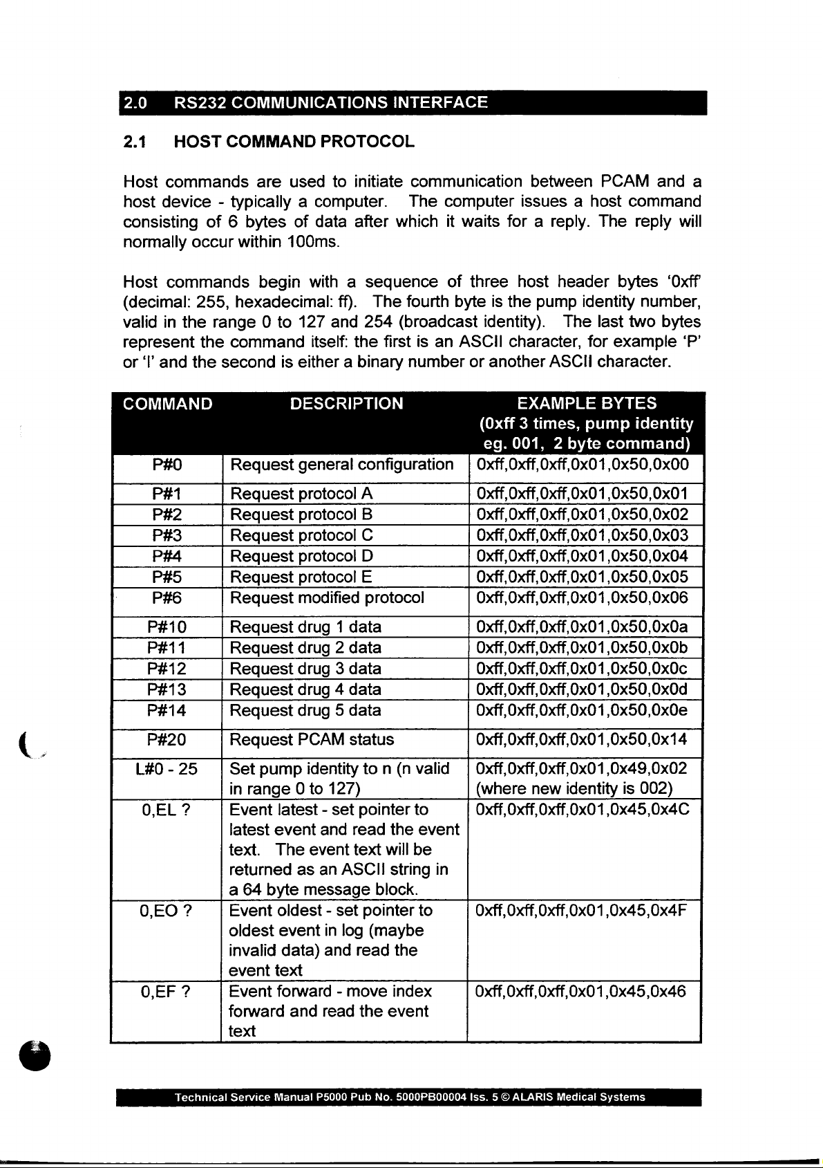
2.1
Host
host
consisting
normally
Host
(decimal:
valid
represent
or
COMMAND
HOST
commands
device - typically a computer.
commands
in
the
‘I’
and
P#1
P#2
P#3
P#4
P#5
P#6
P#10
P#11
P#12
P#13
P#14
P#20
L#0 - 25
0,EL
?
0,EO
O,EF
?
?
COMMAND
of 6 bytes
occur
the
within
255,
hexadecimal:
range 0 to
the
command
second
Request
Request
Request
Request
Request
Request
Request
Request
Request
Request
Request
Request
Request
Set
in
range 0 to
Event
latest
text.
returned
a
64
Event
oldest
invalid
event
Event
forward
text
PROTOCOL
are
used
100ms.
begin
is
DESCRIPTION
pump
latest - set
event
The
byte
oldest - set
event
data)
text
forward - move
and
to
of
data
with a sequence
127
and
itself:
either a binary
general
protocol
protocol
protocol
protocol
protocol
modified
drug 1 data
drug 2 data
drug 3 data
drug 4 data
drug 5 data
PCAM
identity
127)
and
event
as
an
message
in
and
read
initiate
after
ff).
254
the
configuration | Oxff,Oxff,Oxff,0x01,0x50,0x00
A
B
C
D
E
protocol
status
to n (n
pointer
read
text
ASCII
pointer
log
read
the
communication
The
which
The
fourth
(broadcast
first
is
number
valid | Oxff,Oxff,Oxff,0x01,0x49,0x02
to
the
event
will
be
string
block.
to
(maybe
the
index
event
computer
it
waits
of
three
byte
an
ASCII
or
(Oxff 3 times,
eg.
between
issues a host
for a reply.
host
is
the
pump
identity).
character,
another
ASCII
EXAMPLE
001, 2 byte
header
PCAM
The
identity
The
last
for
character.
BYTES
pump
command
bytes
two
example
command)
Oxff,0xff,0xff,0x01,0x50,0x01
Oxff,0xff,0xff,0x01,0x50,0x02
Oxff, Oxff,
Oxff,0xff,0xff,0x01
Oxff,0xff,0xff,0x01,0x50,0x05
Oxff,Oxff,Oxff,0x01,0x50,0x06
Oxff,0xff,0xff,0x01,0x50,0x0a
Oxff,Oxff,Oxff,0x01,0x50,0x0b
Oxff,0xff,0xff,0x01,0x50,0x0c
Oxff,0xff,0xff,0x01,0x50,0x0d
Oxff,0xff,0xff,0x01,0x50,0x0e
Oxff,0xff,0xff,0x01,0x50,0x14
(where
Oxff,0xff,0xff,0x01,0x45,0x4C
in
Oxff,0xff,0xff,0x01,0x45,0x4F
Oxff,0xff,0xff,0x01,0x45,0x46
Oxff,0x01,0x50,0x03
,0x50,0x04
new
identity
is
and
reply
‘Oxff
number,
bytes
identity
002)
a
will
‘P’
Technical
Service
Manual
P5000
Pub
No.
5000PB00004
Iss. 5 ©
ALARIS
Medical
Systems
Page 18
2.1
0,EB
HD
vp
HOST
?
COMMAND
Event
backward
text
Handset
text
“TOTAL = xxxx
The
ASCII
message
Volume
text
“VOLUME
xx.x
back - move
and
demands - returns
text
will
string
block.
infused - return
=
mg”
PROTOCOL
index
read
the
GOOD
be
returned
in a 64
xx.x
ml
byte
MASS
(cont)
Oxff,0xff,0xff,0x01,0x45,0x42
event
the | Oxff,Oxff,Oxff,0x01,0x48,0x44
=
xxxx”.
as
an
the
=
Oxff,0xff,0xff,0x01,0x56,0x49
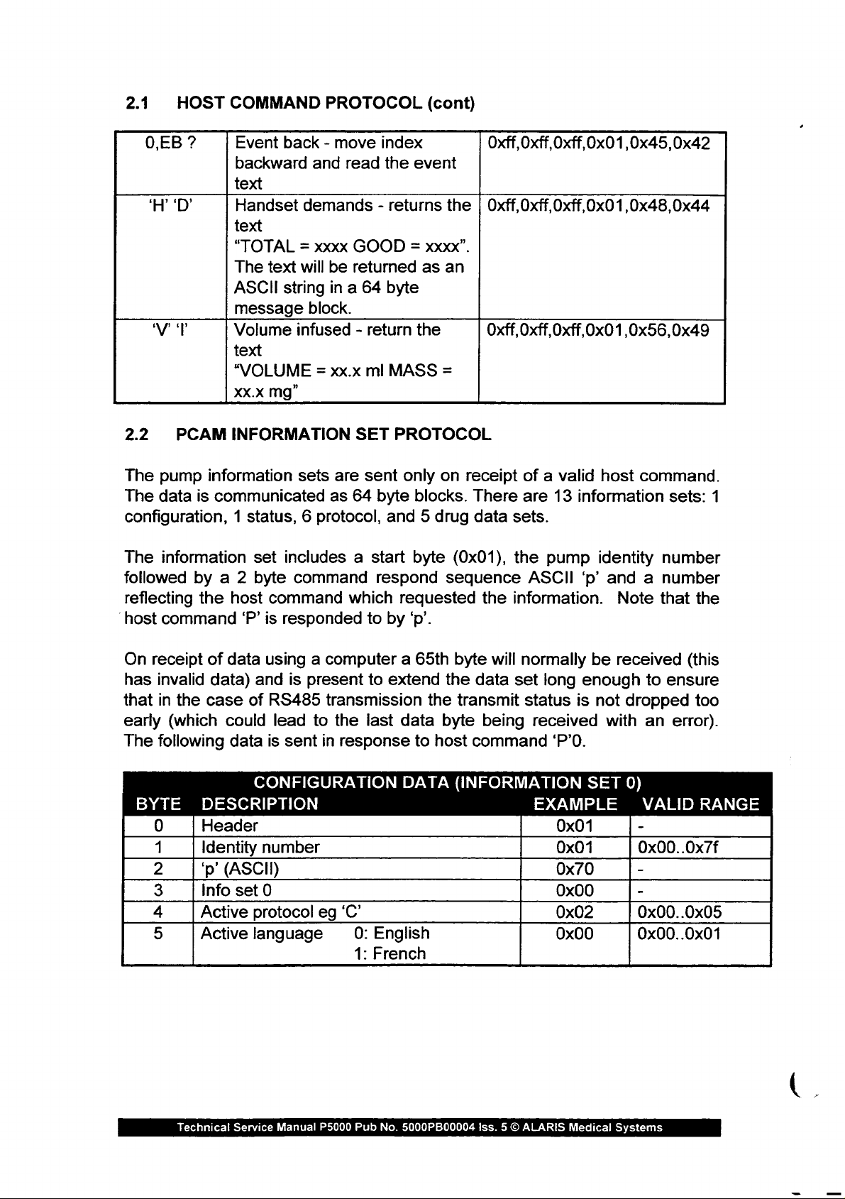
2.2
The
The
configuration, 1 status, 6 protocol,
The
followed
reflecting
‘host
On
has
that
early
The
PCAM
pump
data
information
command
receipt
invalid
in
the
(which
following
BYTE
0
1
2
3
4
5
INFORMATION
information
is
communicated
set
by a 2
the
of
data)
case
DESCRIPTION
Header
Identity
'p'
Info
Active
Active
byte
host
command
‘P’
is
data
using a computer a 65th
and
of
RS485
could
data
(ASCII)
lead
is
CONFIGURATION
number
set
0
protocol
language
SET
sets
are
sent
as
64
byte
includes a start
command
responded
is
present
transmission
to
sent
in
eg
respond
which
to
to
the
last
response
‘C’
0:
English
1:
French
PROTOCOL
only
on
blocks.
and 5 drug
byte
(0x01),
sequence
requested
by
‘p’.
byte
extend
data
the
to
DATA
the
transmit
byte
host
(INFORMATION
receipt
There
data
sets.
the
the
information.
will
normally
data
set
being
command
of a valid
are
13
information
pump
ASCII
status
received
EXAMPLE
long
‘P’0.
0x01
0x01
0x70
0x00
0x02
0x00
'p'
be
enough
is
not
SET
host
command.
sets:
identity
and a number
Note
received
with
number
that
(this
to
ensure
dropped
an
error).
0)
VALID
-
0x00..0x7f
-
-
0x00..0x05
0x00..0x01
1
the
too
RANGE
Technical
Service
Manual
P5000
Pub
No.
5000PB00004
Iss. 5 ©
ALARIS
Medical
Systems
Page 19
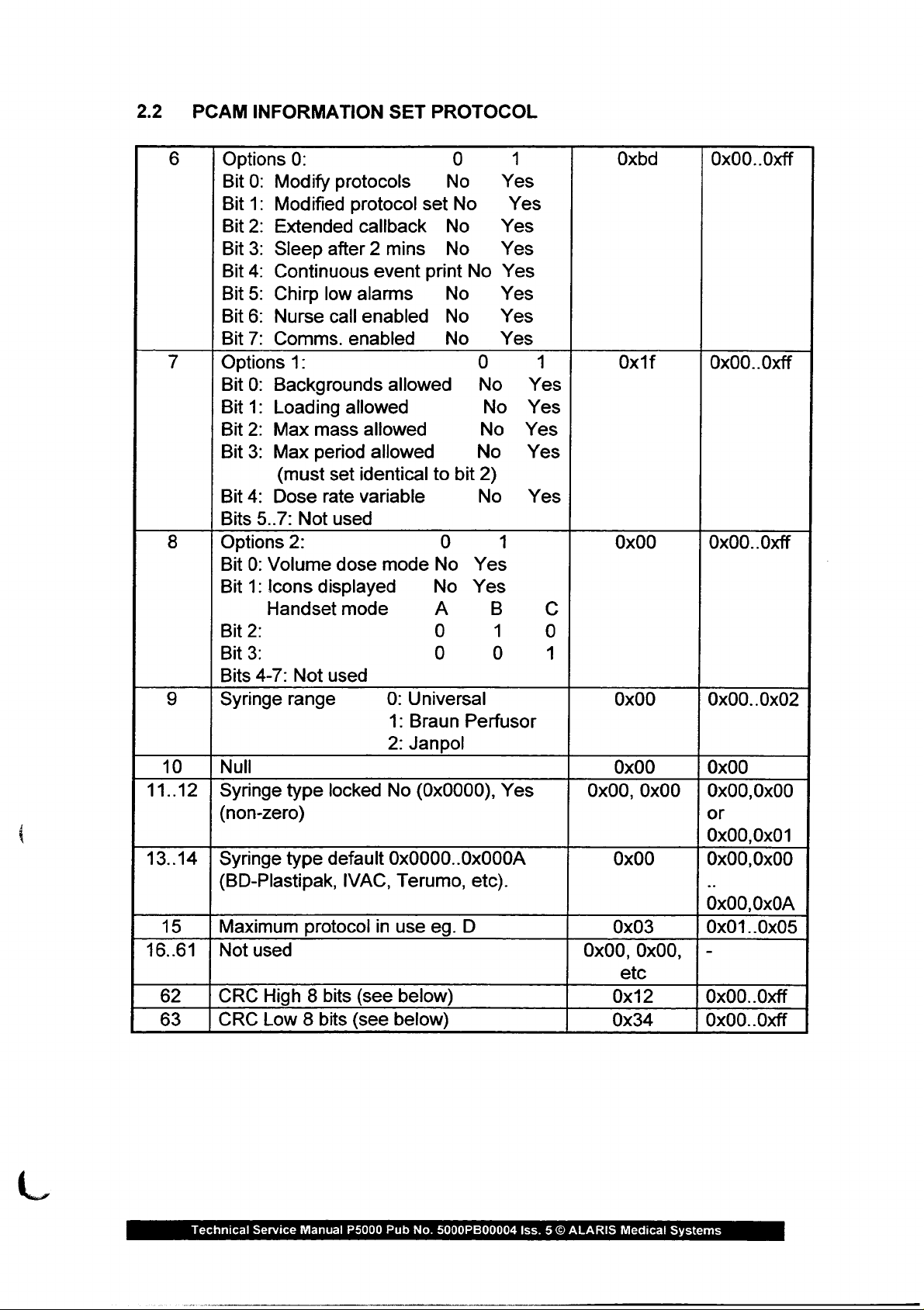
2.2
PCAM
INFORMATION
SET
PROTOCOL
ET,
10
11..12
13..14
15
16..61
62
63
Options
Bit
Bit
Bit
Bit
Bit
Bit
Bit
Bit
Options
Bit
Bit
Bit
Bit
Bit
Bits
Options
Bit
Bit
Bit
Bit
Bits
Syringe
Null
Syringe
(non-zero)
Syringe
(BD-Plastipak,
Maximum
Not
CRC
CRC
0: 0
0:
Modify
1:
Modified
2:
Extended
3:
Sleep
4:
Continuous
5:
Chirp
6:
Nurse
7:
Comms.
0:
Backgrounds
1:
Loading
2:
Max
3:
Max
(must
4:
Dose
5..7:
0:
Volume
1:
Icons
Handset
2:
3:
4-7:
range
type
type
used
High 8 bits
Low 8 bits
protocols
after 2 mins
low
call
1:
mass
period
set
rate
Not
used
2:
dose
displayed
mode
Not
used
locked
default
IVAC,
protocol
protocol
callback
alarms
enabled
enabled
allowed
allowed
identical
variable
(see
(see
event
allowed
allowed
mode
0:
Universal
1:
Braun
2:
Janpol
No
(0x0000),
0x0000..0x000A
Terumo,
in
use
below)
below)
No
set
No
No
No
print
No
No
No
No
to
bit
0
No
No
Yes
A
0
0 0
Perfusor
etc).
eg.
D
0
No
No
No
No
2)
No
Yes
B
1
1
Yes
Yes
Yes
Yes
Yes
Yes
Yes
Yes
1
Yes
Yes
Yes
Yes
Yes
1
C
0
1
Yes
Oxbd
Oxf
0x00
0x00
0x00 0x00
0x00,
0x00,
0x00
0x00
0x03
0x00,
etc
0x12
0x34
0x00..0xff
0x00..0xff
0x00.
.Oxff
0x00..0x02
0x00,0x00
or
0x00,0x01
0x00,0x00
0x00,0x0A
0x01..0x05
0x00..0xff
0x00..0xff
Technical
Service
Manual
P5000
Pub
No.
5000PB00004
Iss. 5 ©
ALARIS
Medical
Systems
Page 20
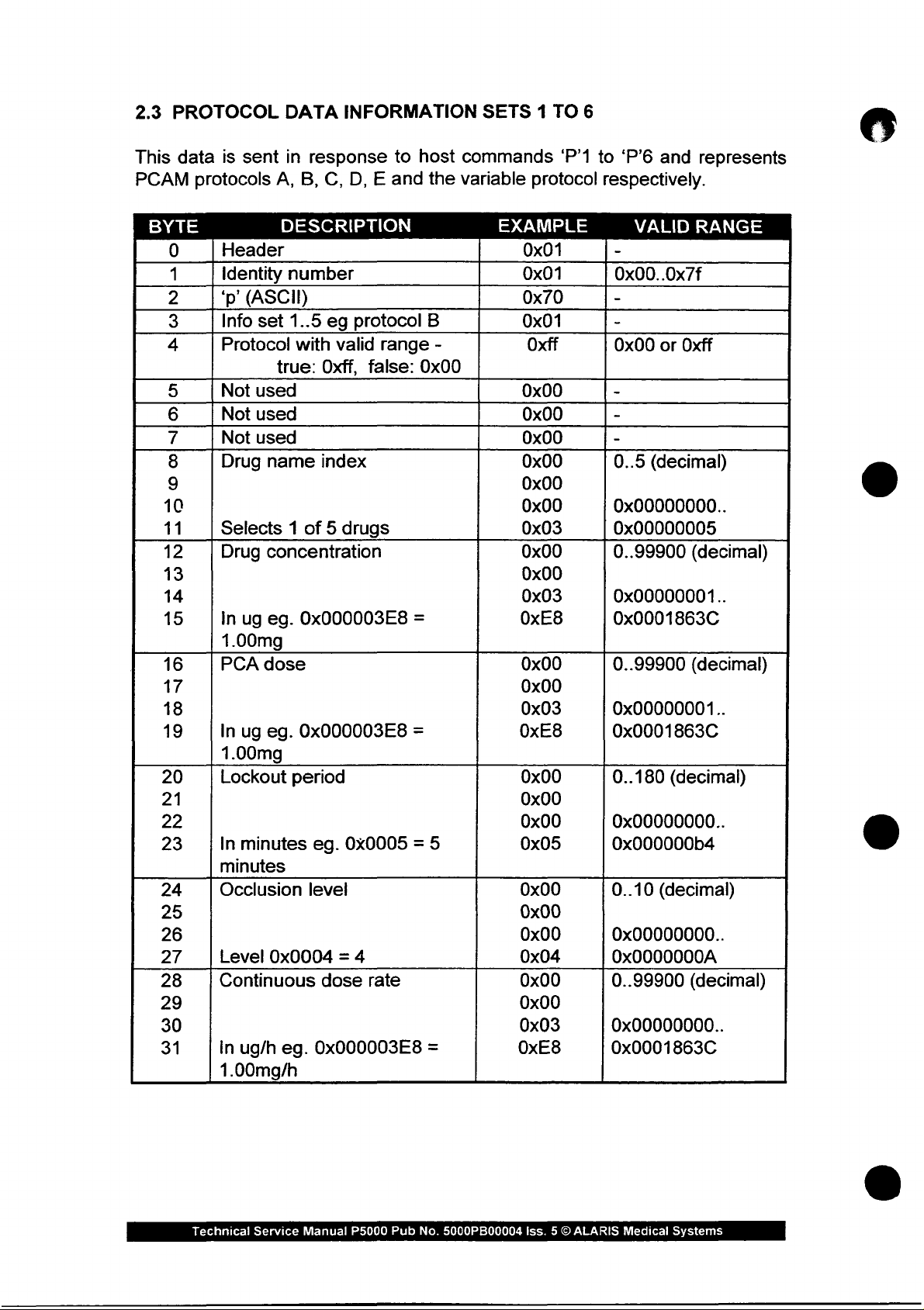
2.3
This
PCAM
PROTOCOL
data
is
sent
protocols
DATA
in
response
A,
B,
INFORMATION
to
C,
D, E and
host
the
SETS 1 TO
commands
variable
6
‘P’1
to
protocol
respectively.
‘P’6
and
represents
BYTE
0
1
2
3
4
5
6
7
8
9
10
11
12
13
14
15
16
17
18
19
20
21
22
23
24
25
26
27
28
29
30
31
Header
Identity
‘p
Info
Protocol
Not
Not
Not
Drug
Selects 1 of 5 drugs
Drug
In
1.00mg
PCA
In
1.00mg
Lockout
In
minutes
Occlusion
Level
Continuous
In
1.00mg/h
DESCRIPTION
number
(ASCII)
set
1..5
eg
with
true:
Oxff,
used
used
used
name
concentration
ug
eg.
dose
ug
eg.
minutes
0x0004 = 4
ug/h
index
0x000003E8
0x000003E8
period
eg.
level
dose
eg.
0x000003E8
protocol
valid
range
false:
=
=
0x0005 = 5
rate
B
-
0x00
=
EXAMPLE
0x01
0x01
0x70
0x01
Oxff
0x00
0x00
0x00
0x00
0x00
0x00
0x03
0x00
0x00
0x03
OxE8
0x00
0x00
0x03
OxE8
0x00
0x00
0x00
0x05
0x00
0x00
0x00
0x04
0x00
0x00
0x03
OxE8
VALID
-
0x00..0x7f
-
-
0x00
or
-
-
-
0..5
(decimal)
0x00000000..
0x00000005
0..99900
0x00000001..
0x0001863C
0..99900
0x00000001..
0x0001863C
0..180
0x00000000..
0x000000b4
0..10
0x00000000..
0x0000000A
0..99900
0x00000000..
0x0001863C
(decimal)
(decimal)
RANGE
Oxff
(decimal)
(decimal)
(decimal)
Technical
Service
Manual
P5000
Pub
No.
5000PB00004
Iss. 5 ©
ALARIS
Medical
Systems
Page 21
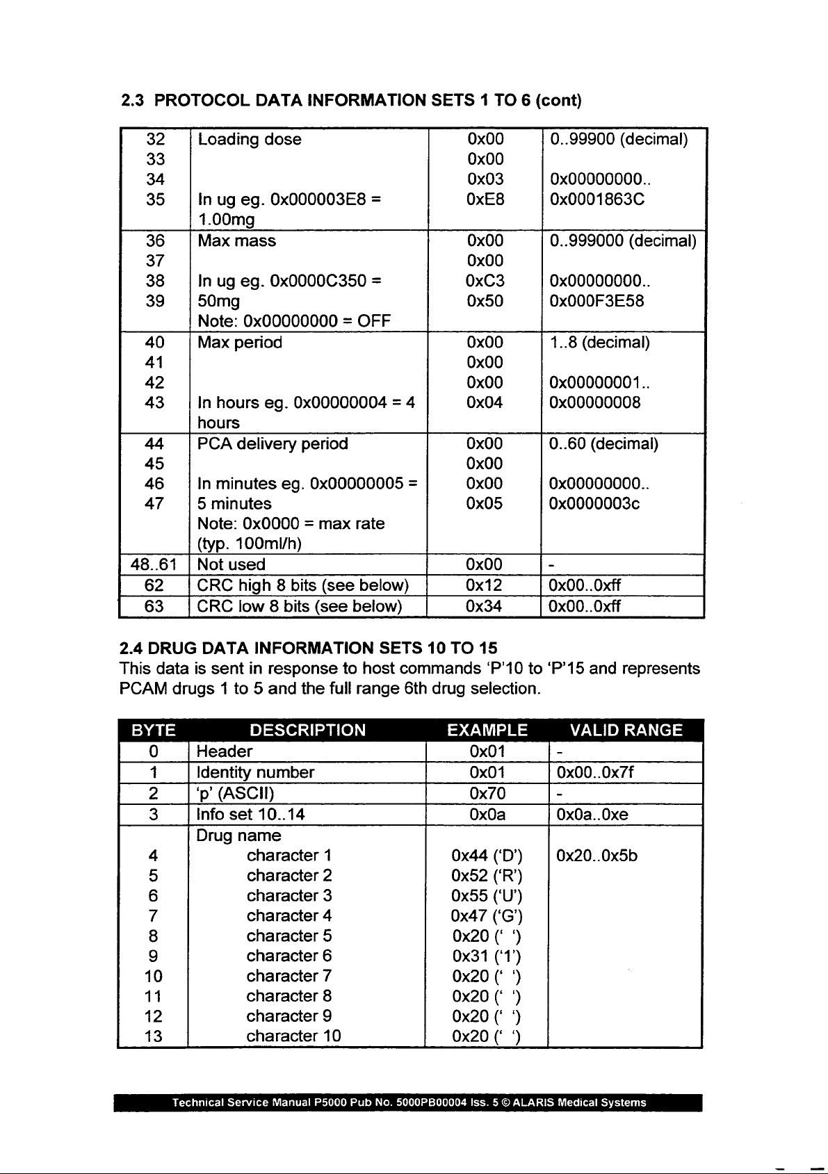
2.3
PROTOCOL
32
33
34
35
36
37
38
39
40
41
42
43
44
45
46
47
48..61 | Not
62
63
Loading
In
ug
1.00mg
Max
In
ug eg.
50mg
Note:
Max
In
hours
hours
PCA
In
minutes
5
minutes
Note:
(typ.
used
CRC
CRC
DATA
dose
eg.
mass
0x00000000 = OFF
period
eg.
delivery
0x0000 = max
100mi/h)
high 8 bits
low 8 bits
INFORMATION
0x000003E8
0x0000C350
0x00000004 = 4
period
eg.
0x00000005
rate
(see
below)
(see
below)
=
=
SETS 1 TO 6 (cont)
0x00
0x00
0x03
OxE8
0x00
0x00
0xC3
0x50
0x00
0x00
0x00
0x04
0x00
0x00
=
0x00
0x05
0x00
0x12
0x34
0..99900
0x00000000..
0x0001863C
0..999000
0x00000000..
0x000F3E58
1..8
0x00000001..
0x00000008
0..60
0x00000000..
0x0000003c
-
0x00..0xff
0x00.
(decimal)
(decimal)
(decimal)
(decimal)
.Oxff
2.4
DRUG
This
data
PCAM
BYTE
0
1
2
3
4
5
6
7
8
9
10
11
12
13
DATA
is
sent
drugs 1 to 5 and
Header
Identity
'p'
Info
Drug
INFORMATION
in
DESCRIPTION
number
(ASCII)
set
10..14
name
character
character
character
character
character
character
character
character
character
character
response
the
full
1
2
3
4
5
6
7
8
9
10
to
host
range
SETS
commands
6th
10
TO
15
‘P’10
drug
selection.
EXAMPLE
0x01
0x01
0x70
0x0a
0x44
0x52
0x55
0x47
0x20
0x31
0x20
0x20
0x20
0x20
to
(‘D’)
(‘R’)
(‘U’)
(‘GC’)
(‘
‘)
(‘1’)
(*
9)
(* 9)
(*
9
(*
9
‘P’15
and
VALID
-
0x00..0x7f
-
0x0a..0xe
0x20..0x5b
represents
RANGE
Technical
Service
Manual
P5000
Pub
No.
5000PB00004
Iss. 5 O
ALARIS
Medical
Systems
Page 22

2.4
DRUG
14
15
16
17
18
19
20
21
22
23
24
25
26
27
28
29
30
31
32
33
34
35
36
37
38
39
40
41
42
43
44
45
46
47
48..61
62
63
DATA
Drug
Not
Minimum
In
0.5mg/ml
Maximum
In
2.0mg/ml
Minimum
In
5
minutes
Maximum
In
10
Minimum
In
10ug
Maximum
In
2.0mg
Maximum
In
2.0mg/h
Maximum
In
| Not
CRC
CRC
INFORMATION
name
used
drug
ug/ml
ug/ml
minutes
minutes
ug
ug
ug/h
ug
eg.
drug
eg.
lockout
lockout
minutes
PCA
eg.
0x0000000a
PCA
eg.
0x000007D0
continuous
eg.
loading
eg.
0x00002710
used
high 8 bits
low 8 bits
string
concentration
0x000001F4
concentration
0x000007D0
eg.
0x00000005
eg.0x0000000A
bolus
bolus
0x000007D0
SETS
terminator
=
=
=
=
dose
=
dose
=
dose
=
dose
10
TO
15
(cont)
0x00
0x00
0x00
0x00
0x01
OxF4
0x00
0x00
0x07
0xD0
0x00
0x00
0x00
0x05
0x00
0x00
0x00
Ox0A
0x00
0x00
0x00
0x0a
0x00
0x00
0x07
OxDO
0x00
0x00
0x07
OxDO
0x00
0x00
0x27
0x10
0x00
0x12
0x34
-
-
0..99900
0x00000001..
0x0001863C
Min..99900
(decimal)
Min
conc..
0x0001863C
0..180
Min..180
0..99900
0x00000001..
0x0001836C
Min..99900
(decimal)
Min
0x0001836C
0..99900
0..99900
-
-
-
(decimal)
dose..
(decimal)
(decimal)
(decimal)
(decimal)
(decimal)
Technical
Service
Manual
P5000
Pub
No.
5000PB00004
Iss. 5 O
ALARIS
Medical
Systems
Page 23
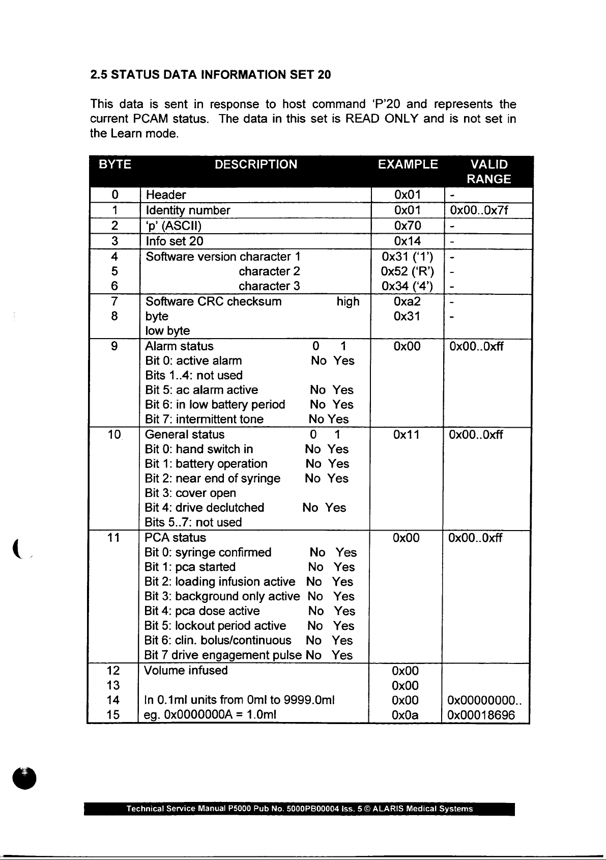
2.5
STATUS
This
data
current
the
Learn
is
PCAM
mode.
DATA
sent
in
status.
INFORMATION
response
The
to
data
host
in
SET
this
20
command
set
is
READ
‘P’20
ONLY
and
and
represents
is
not
set
the
in
BYTE
0
1
2
3
4
5
6
7
8
9
10 | General
11
12
13
14
15
Header
Identity
'p'
Info
Software
Software
byte
low
Alarm
Bit
Bits
Bit
Bit
Bit
Bit
Bit
Bit
Bit
Bit
Bits
PCA
Bit
Bit
Bit
Bit
Bit
Bit
Bit
Bit 7 drive
Volume
In
0.1ml
eg.
number
(ASCII)
set
20
version
CRC
byte
status
0:
active
1..4:
5:
ac
6:
in
7:
intermittent
0:
hand
1:
battery
2:
near
3:
cover
4:
drive
5..7:
status
0:
syringe
1:
pca
2:
loading
3:
background
4:
pca
5:
lockout
6:
clin.
0x0000000A = 1.0ml
alarm
not
alarm
low
battery
status
switch
end
open
declutched
not
started
dose
bolus/continuous
engagement
infused
units
DESCRIPTION
character
character
character
checksum
used
active
period
tone
in
operation
of
syringe No
used
confirmed
infusion
active
period
from
active
only
active
Oml
active
pulse
to
1
2
3
0
No
No
No
No
Yes
0
No
Yes
No
Yes
Yes
No
Yes
No
No
No
No
No
No
No
No
9999.0ml
high
1
Yes
Yes
Yes
1
Yes
Yes
Yes
Yes
Yes
Yes
Yes
Yes
EXAMPLE
0x01
0x01
0x70
0x14
0x31
Ox52
0x34
(‘1’) | -
(‘R’) | -
(‘4’) | -
0xa2
0x31
0x00
0x11
0x00
0x00
0x00
0x00
Ox0a
VALID
RANGE
-
0x00..0x7f
-
-
-
-
0x00..0xff
0x00..0xff
0x00.
.Oxff
0x00000000..
0x00018696
Technical
Service
Manual
P5000
Pub
No.
5000PB00004
iss. 5 ©
ALARIS
Medical
Systems
Page 24
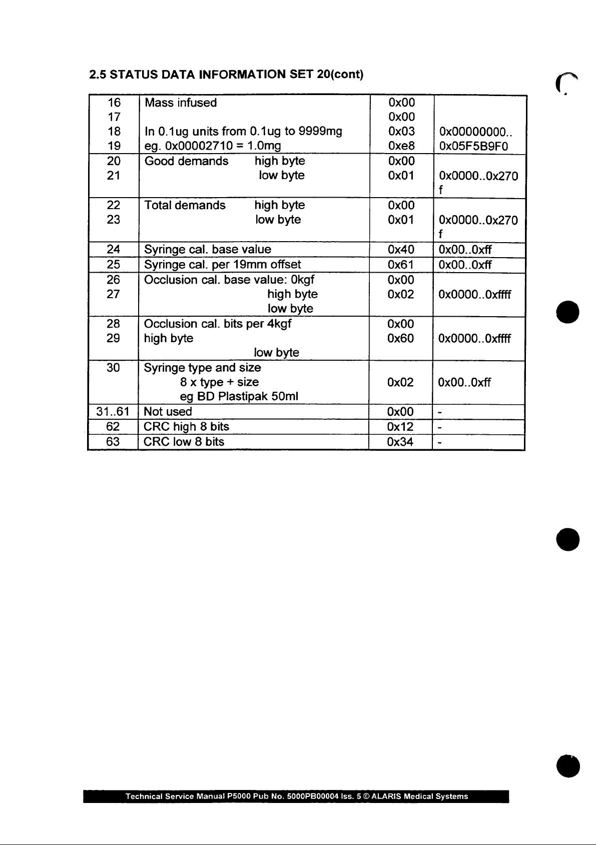
2.5
STATUS
16
17
18
19
20
21
22
23
24
25
26
27
28
29 high
30
31..61 | Not
62
63
DATA
Mass
In
0.1ug
eg.
0x00002710 = 1.0mg
Good
Total
Syringe
Syringe
Occlusion
Occlusion
Syringe
used 0x00
CRC
CRC
INFORMATION
infused
units
from
demands
demands
cal.
base
cal.
per
19mm
cal.
base
cal.
bits
byte
type
and
size
8 x type + size
eg
BD
Plastipak
high 8 bits
low 8 bits
0.1ug
high
low
high
low
value
value:
high
low
per
4kgf
low
SET
to
9999mg
byte
byte
byte
byte
offset
Okgf
byte
byte
byte
50ml
20(cont)
0x00
0x00
0x03
Oxe8
0x00
0x01
0x00
0x01
0x40
0x61
0x00
0x02
0x00
0x60
0x02
0x12
0x34
0x00000000..
0x05F5B9F0
0x0000..0x270
f
0x0000..0x270
f
0x00.
0x00..0xff
0x0000..Oxffff
0x0000..Oxffff
0x00.
-
-
-
.Oxff
.Oxff
Technical
Service
Manual
P5000
Pub
No.
5000PB00004
Iss. 5 ©
ALARIS
Medical
Systems
Page 25
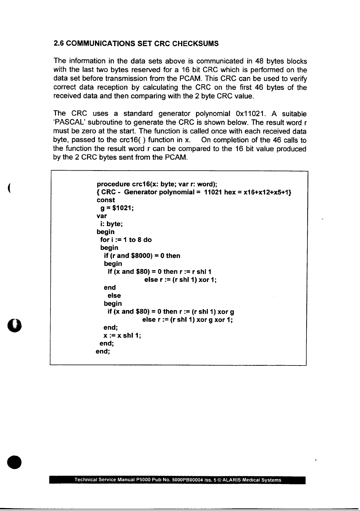
2.6
COMMUNICATIONS
The
information
with
the
last
data
set
before
correct
received
data
data
in
the
two
bytes
transmission
reception
and
then
SET
CRC
data
sets
reserved
from
by
calculating
comparing
CHECKSUMS
above
for a 16
the
PCAM.
the
with
the 2 byte
is
communicated
bit
CRC
This
CRC
on
CRC
which
CRC
the
value.
in
48
is
performed
can
be
first
46
bytes
used
bytes
blocks
on the
to
verify
of
the
The
‘PASCAL’
must
byte,
the
by
CRC
be
passed
function
the 2 CRC
uses
subroutine
zero
at
the
to
the
the
result
bytes
procedure
{
CRC - Generator
const
g =
var
i:
byte;
begin
for i := 1 to 8 do
begin
if
begin
if
end
else
begin
if
end;
x
:=x
end;
end;
a
standard
to
generate
start.
crc16( ) function
sent
$1021;
(r
and
(x
(x
The
word r can
from
crc16(x:
$8000) = 0
and
$80) = O
else r :=
and
$80) = 0
else r :=
shl
1;
function
the
generator
the
in
be
PCAM.
byte;
polynomial = 11021
then
then r := r shi
(r
then r :=
(r
shl
polynomial
CRC
compared
var
is
x.
shl
is
shown
called
On
r:
word);
1)
xor
(r
shi
1)
xor g xor
once
completion
to
1
1;
1)
xorg
0x11021.
below.
with
the
hex = x16+x12+x5+1}
1;
16
The
each
of
bit
A
result
received
the
46
value
produced
suitable
word
calls
r
data
to
Technical
Service
Manual
P5000
Pub
No.
5000PB00004
Iss. 5 ©
ALARIS
Medical
Systems
Page 26
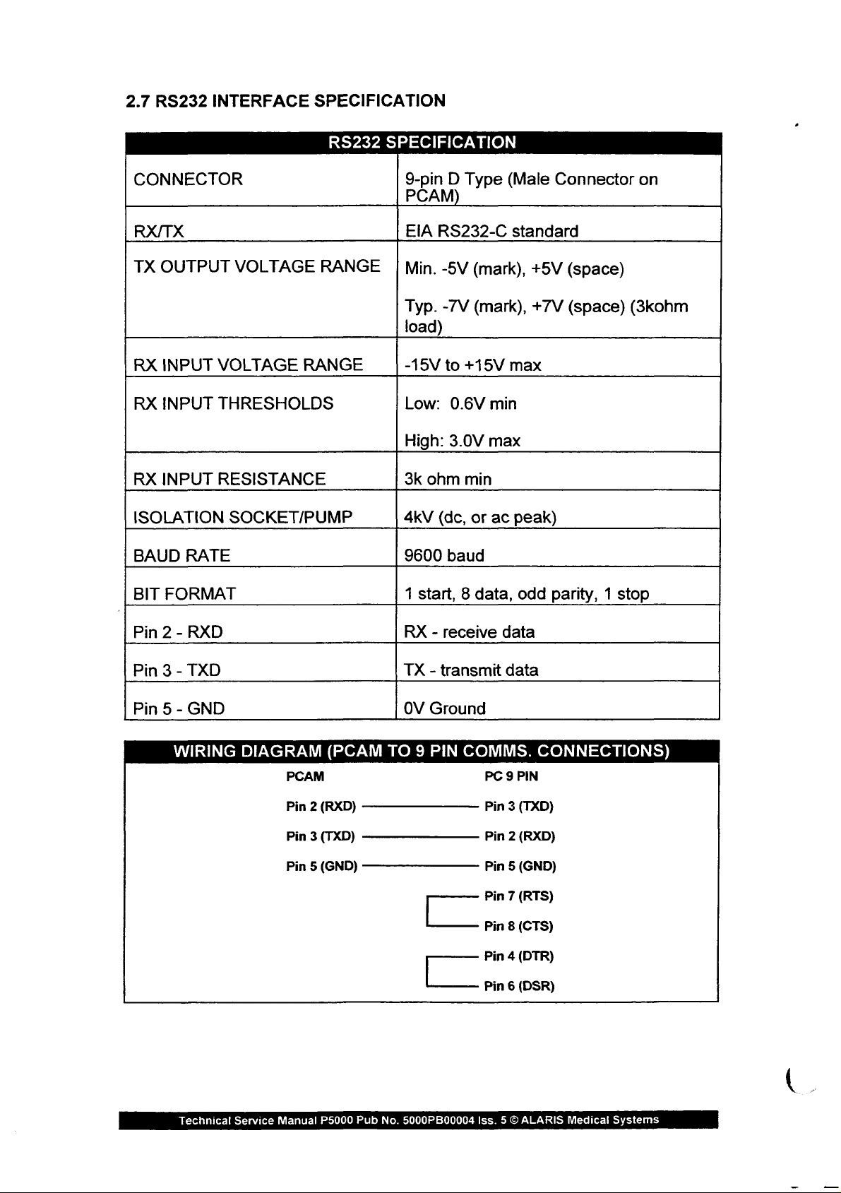
2.7
RS232
INTERFACE
SPECIFICATION
CONNECTOR
RX/TX
TX
OUTPUT
RX
INPUT
RX
INPUT
RX
INPUT
ISOLATION
VOLTAGE
VOLTAGE
THRESHOLDS
RESISTANCE
SOCKET/PUMP
RS232
RANGE
RANGE
SPECIFICATION
9-pin D Type
PCAM)
EIA
RS232-C
Min.
-5V
(mark),
(mark),
-7V
Typ.
load)
-15V
to
+15V
Low:
High:
3k
4kV
3.0V
ohm
(dc,
0.6V
min
or
min
max
ac
(Male
standard
max
+5V
+7V
peak)
Connector
(space)
(space)
(3kohm
on
BAUD
BIT
Pin 2 -
Pin 3 -
Pin 5 -
RATE
FORMAT
RXD
TXD
GND
WIRING
DIAGRAM
(PCAM
PCAM
Pin 2 (RXD)
Pin 3 (TXD)
Pin 5 (GND)
9600
RX - receive
TX - transmit
OV
TO 9 PIN
baud
1
start, 8 data,
Ground
COMMS.
Pin 7 (RTS)
Pin 8 (CTS)
Pin 4 (DTR)
odd
parity, 1 stop
data
data
CONNECTIONS)
PC 9 PIN
Pin 3 (TXD)
Pin 2 (RXD)
Pin 5 (GND)
Technical
Service
Manual
P5000
Pub
No.
5000PB00004
Pin 6 (DSR)
Iss. 5 ©
ALARIS
Medical
Systems
Page 27
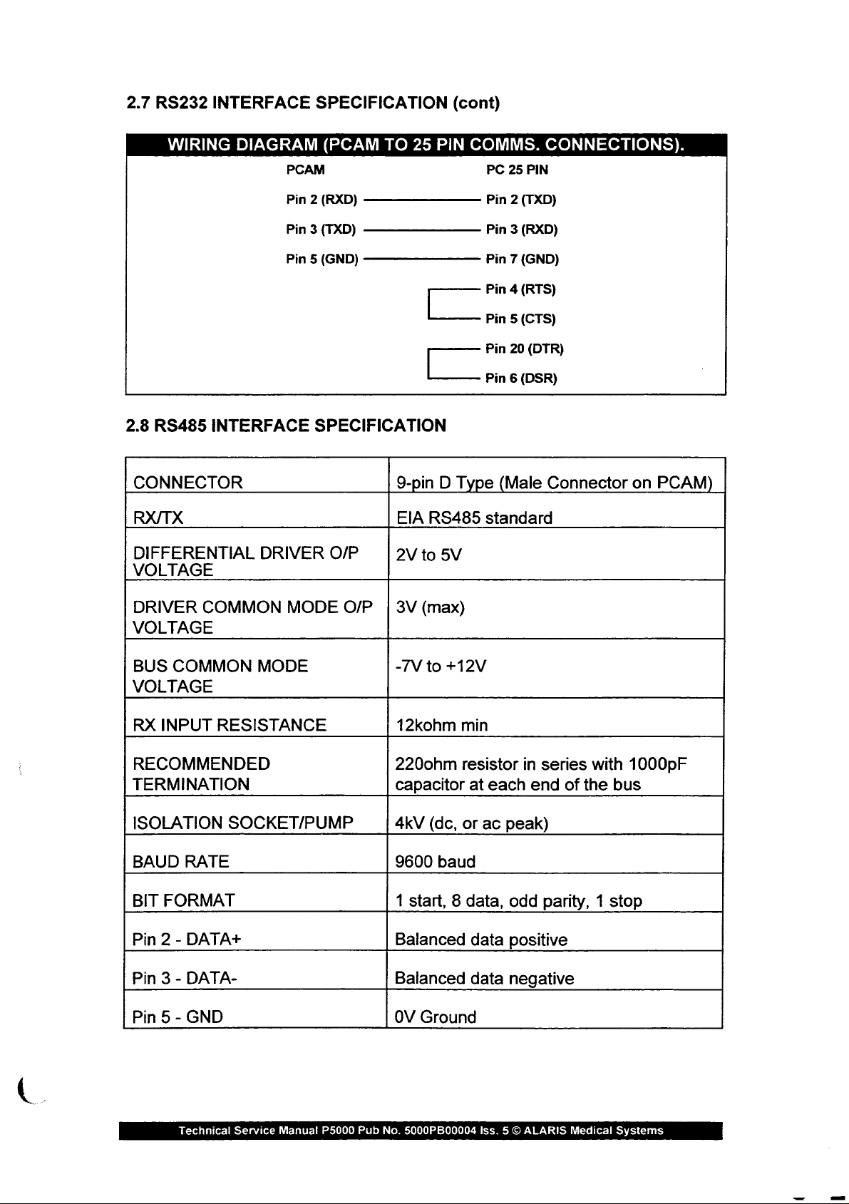
2.7
RS232
INTERFACE
SPECIFICATION
(cont)
WIRING
2.8
RS485
CONNECTOR
RX/TX
DIFFERENTIAL
VOLTAGE
INTERFACE
DIAGRAM
PCAM
Pin 2 (RXD)
Pin 3 (TXD)
Pin 5 (GND) - ㅡ
DRIVER
(PCAM
SPECIFICATION
O/P
TO
25
—————————
ㅡ
9-pin D Type
EIA
2V
to
PIN
RS485
5V
COMMS.
PC
25
PIN
Pin 2 (TXD)
Pin 3 (RXD)
Pin 7 (GND)
Pin 4 (RTS)
Pin 5 (CTS)
Pin
20
(DTR)
Pin 6 (DSR)
(Male
standard
CONNECTIONS).
Connector
on
PCAM)
DRIVER
VOLTAGE
BUS
VOLTAGE
RX
RECOMMENDED
TERMINATION
ISOLATION
BAUD
BIT
Pin 2 -
Pin
Pin 5 -
COMMON
COMMON
INPUT
RATE
FORMAT
DATA+
3-
DATA-
GND
RESISTANCE
SOCKET/PUMP
MODE
MODE
O/P | 3V
(max)
-7V
to
12kohm
220ohm
capacitor
4kV
(dc,
9600 baud
1
start, 8 data,
Balanced
Balanced
OV
Ground
+12V
min
resistor
at
each
or
ac
data
data
in
series
end
of
peak)
odd
parity, 1 stop
positive
negative
with
the
1000pF
bus
Technical
Service
Manual
P5000
Pub
No.
5000PB00004
Iss. 5 ©
ALARIS
Medical
Systems
Page 28
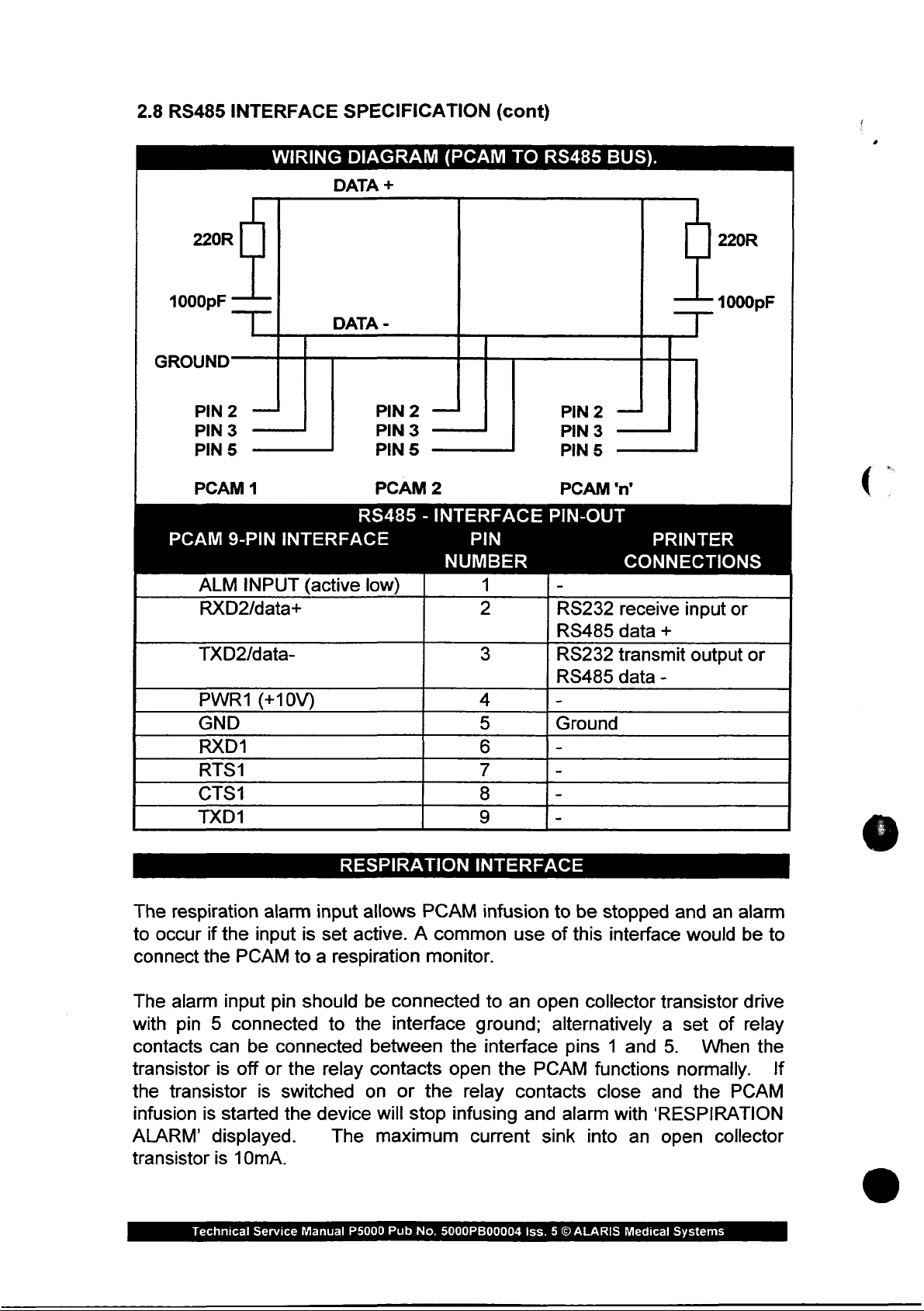
2.8
RS485
INTERFACE
SPECIFICATION
(cont)
220R
1000pF
GROUND
PIN2
PIN 3 一 一 一
PIN 5 一 一 一 一
PCAM
PCAM
ALM
RXD2/data+
TXD2/data-
PWR1
GND
RXD1
RTS1
CTS1
TXD1
WIRING
—
1
9-PIN
INPUT
(+10V)
DIAGRAM
DATA
DATA
一
INTERFACE
(active
(PCAM
+
-
PIN2
PIN
3
PIN 5 一 一 一
PCAM
RS485 - INTERFACE
low)
—
2
NUMBER
TO
一
PIN
1 -
2
3
4
5
6
7
8
9
RS485
PIN2
PIN
3
PIN
5
PCAM
PIN-OUT
RS232
RS485
RS232
RS485
-
Ground
-
-
-
-
BUS).
—
'n'
PRINTER
CONNECTIONS
receive
data
transmit
data
input
+
-
220R
1000pF
or
output
or
The
respiration
to
occur
connect
The
with
contacts
transistor
the
infusion
ALARM’
transistor
if
the
the
alarm
pin 5 connected
can
is
transistor
is
started
displayed.
is
Technical
alarm
input
PCAM
input
be
off
or
is
10mA.
Service
RESPIRATION
input
allows
is
set
active. A common
to a respiration
pin
should
connected
the
switched
the
device
Manual
be
to
the
relay
on
The
P5000 Pub
between
contacts
will
maximum
PCAM
monitor.
connected
interface
the
open
or
the
relay
stop
infusing
current
No.
5000PB00004
INTERFACE
infusion
to
ground;
interface
the
to
use
of
an
open
alternatively a set
PCAM
contacts
and
sink
Iss. 5 ©
be
stopped
this
interface
collector
pins 1 and
functions
close
alarm
into
ALARIS
with
an
Medical
and
an
alarm
would
transistor
5.
normally. _ If
and
the
‘RESPIRATION
open
Systems
be
drive
of
relay
When
the
PCAM
collector
to
Page 29
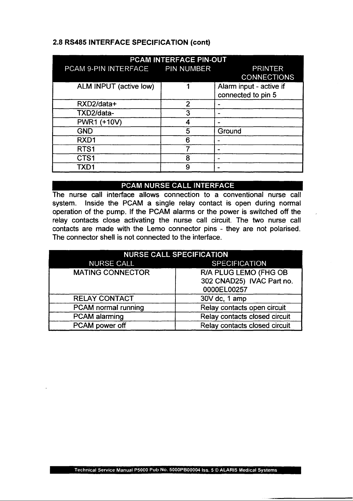
2.8
RS485
INTERFACE
SPECIFICATION
(cont)
PCAM
ALM
The
system.
operation
relay
contacts
The
RXD2/data+
TXD2/data-
PWR1
GND
RXD1
RTS1
CTS1
TXD1
nurse
contacts
connector
9-PIN
INPUT
call
Inside
of
the
are
made
INTERFACE
(active
(+10V)
PCAM
interface
the
pump.
close
with
shell
is
PCAM
PCAM
If
the
activating
the
not
INTERFACE
low)
NURSE
allows
a
single
PCAM
Lemo
connected
PIN
NUMBER
CALL
connection
relay
alarms
the
nurse
connector
to
the
PIN-OUT
cm.
δι»
NOMI
(O
INTERFACE
contact
or
call
interface.
Alarm
connected
Ground
to a conventional
is
the
power
circuit.
pins - they
PRINTER
CONNECTIONS
input - active
to
pin
5
nurse
open
The
during
is
switched
two
are
not
nurse
polarised.
if
call
normal
off
the
call
NURSE
MATING
RELAY
PCAM
PCAM
PCAM
CALL
CONNECTOR
CONTACT
normal
alarming
power
running
off
NURSE
CALL
SPECIFICATION
SPECIFICATION
R/A
PLUG
302
CNAD25)
0000EL00257
30V
dc, 1 amp
Relay
Relay
Relay
LEMO
contacts
contacts
contacts
(FHG
IVAC
open
closed
closed
Part
circuit
OB
no.
circuit
circuit
Technical
Service
Manual
P5000
Pub
No.
5000PB00004
Iss. 5 ©
ALARIS
Medical
Systems
Page 30

3.0
PRODUCT
FEATURES,
UPDATES
AND
ENHANCEMENTS
Product
and
The
updates
revision
software
described
The
following
have
been
pumps.
and
status
of
status
in
this
service
sub-sections
introduced
enhancements
the
resident
may
be
interrogated
manual.
describe
during
ongoing
are
software
the
development
generally
of
the
equipment.
by
following
updates
identified
the
self
and
enhancements
of
our
range
by
the
test
procedure
of
version
that
syringe
Technical
Service
Manual
P5000
Pub.
No.
5000PB00004
Iss. 5 ©
ALARIS
Medical
Systems
Page 31
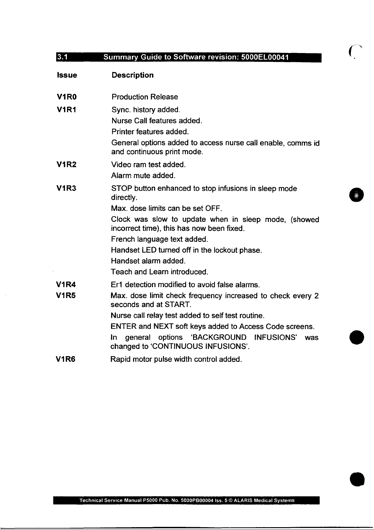
Summary
Guide
to
Software
revision:
5000EL00041
Issue
VARO
V1R1
V1R2
V1R3
Description
Production
Sync.
Nurse
Printer
General
and
Video
Alarm
STOP
history
Call
features
options
continuous
ram
mute
button
directly.
Max. dose
Clock
incorrect
French
Handset
was
time),
language
LED
Release
added.
features
added.
added
print
test
added.
added.
enhanced
limits
slow
this
turned
can
to
text
added.
to
mode.
to
be
set
update
has
now
added.
off
in
access
stop
infusions
OFF.
when
been
the
lockout
nurse
in
sleep
fixed.
phase.
call
in
sleep
enable,
mode
mode,
comms
(showed
id
V1R4
V1RS
V1R6
Handset
Teach
Er1
Max. dose
seconds
Nurse
ENTER
In
changed
Rapid
alarm
and
detection
and
call
and
general
to
motor
added.
Learn
limit
relay
introduced.
modified
check
at
START.
test
NEXT
added
soft
options
‘CONTINUOUS
pulse width
to
avoid
frequency
keys
to
self
added
false
increased
test
‘BACKGROUND
INFUSIONS’.
control
added.
alarms.
routine.
to
Access
to
check
Code
screens.
INFUSIONS’
every
was
2
Technical
Service
Manual
P5000
Pub.
No.
5000PB00004
Iss. 5 ©
ALARIS
Medical
Systems
Page 32

Summary
Guide
to
Software
Revision:
5000EL00057
Issue
V2RO
Description
Language
Dosing
Separate
C
want
be
Handset
Self
4.1
4.2
Battery
added.
which
the
aware
cancel
Cover
Handset
mode
handset
seem
handset
that
Modes
Operation
Extended
Rapid
Sleep
Maximum
Repeated
Backlight
Pressure
Maximum
Reset
Comms
will
volume
to
single
off
icon
service
Protocol.
ug
necessary
limit
and
protocol
options:
has
been
operation
to
meet
light
the
lamp
A,
B,
certain
alarm
closed.
replaced.
and
Callback
added.
added.
Limit
on
run
alarm - on
during
(top)
with a tapered
dose
icon
log
confirm
This
dosing
units.
to
change
and
Because
information.
English,
introduced.
the
requirements
to
extinguish
is
lit
C.
conditions
Near
display
mute
after 2 mins
sleep
mode
(lower)
stage
has
been
the
extended
the
size
French
modes
or
and
(were
(since
flashing
at
German.
A,
of
users
the
all
following
End
of
syringe
messages
added.
added.
added.
indicator
indicates a glass
added.
added.
drastically
of
these
of
the
mass
changes
variables
modified
dose
B)
to
give
who
patient
times):
mute:
bottle
added.
ranges
it
was
storing
A,
B,
do
not
should
to
cope
down
the
drug
Technica!
16
bit
cyclic
information
method
receives
however
It
will
software
of
standard
data
it
is
be
necessary
comms.
Furthermore
between
Service
Manual
pumps
P5000
redundancy
set.
CRCs
protocol
they
can
an
essential
to
information
it
is
NOT
with
V1
Pub.
No.
5000PB00004
checks
are
an
error
ignore
include
part
sets
the
of
both
possible
software
have
been
efficient
the
to
Iss. 5 ©
and
protection.
CRC
if
learn
V1
software
in
the
directions
use
TEACH / LEARN
and
V2
ALARIS
added
highly
When
it
is
not
required
mode
software.
Medical
protocol.
and
Systems
to
each
reliable
the
user
-
V2
for
use.
mode
Page 33

Issue
Description
V2R1
V2R2
V2R3
V2R4
Language
Continuous
NEOI
Check
Display
Drug
Dutch
Speed
24
Dutch
Max
Callback
Power
revised
Error
Er32
Volume
by
bolus
flag
30min
mode
name
text
constant
Hour
log
text
dose
timer
up
to
Codes
to
Er38
Measurement.
the
motor
was
watchdog.
Watchdog
Max
dose
Clinician
Bolus
options:
maximum
detection
period
defaults
German
clear
from
update
“MED
limit
every
modified.
adjustment.
clearing
modified.
modifications.
at
power
accuracy
The
self
repeat
if a test
introduced.
A
gearbox
added.
momentarily
Timing.
icon
corrected.
volume
adjustment
and
shown
on
declutch.
low
battery.
0.5sec.
1”
introduced.
up.
1%.
power-up
appeared
check
Dutch
as
20.0ml/h.
watchdog
for
negative
unwinding
to
add
introduced.
tests
to
fail.
volumes
at
the
continuous
were
caused
end
rate.
of
a
V2R5
V2R6
Max
Dose
False
Swedish
Maximum
Dose
Syringe
Occlusion
Occlusion
Drug
PCA
to
PCA
epidural
syringe
and
name
lockout
RUN
Dose
Language
Type
before
use.
Occlusion
Addition
of
log
anomaly
alarms.
limits
programmable
Lockout
Locking
Limits
icon
display
entry
increased
speed
retained
the
of
Omg
levels
now
Evans
in
volume
added.
Limits.
added.
changed
improved.
if
the
lockout
expires.
available
selectable
Rapiject
Syringe.
for
to
allow
pump
to
prevent
mode.
Loading
epidural
to
match
is
switched
with
the
handset
each
Dose,
sets
P3000
to
SET
Continuous
with
deliveries
protocol.
filters.
and
P7000.
and
then
for
Technical
Service
Manual
P5000
Pub.
No.
5000PB00004
Iss. 5 ©
ALARIS
Medical
Systems
Page 34
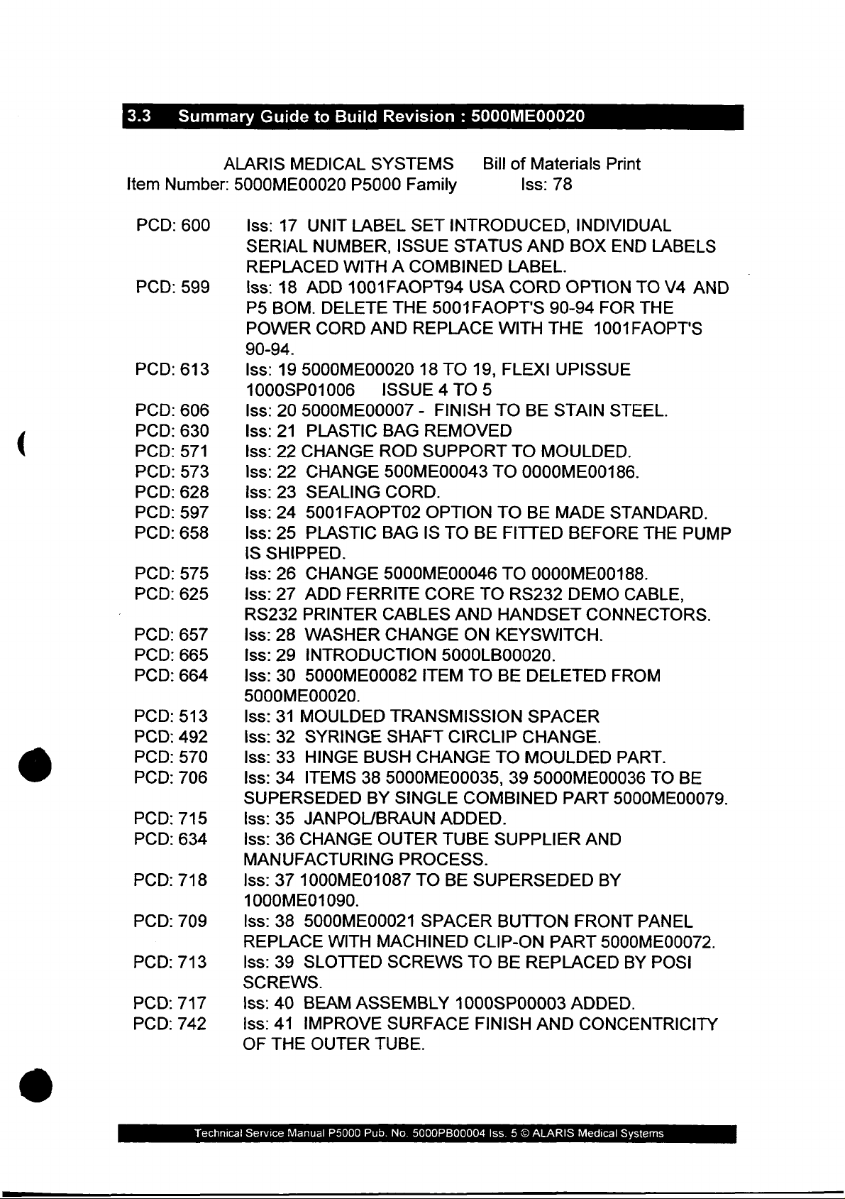
3.3
Summary
Guide
to
Build
Revision : 5000ME00020
(
©
Item
PCD:
PCD:
PCD:
PCD:
PCD:
PCD:
PCD:
PCD:
PCD:
PCD:
PCD:
PCD:
PCD:
PCD:
PCD:
PCD:
PCD:
PCD:
PCD:
PCD:
PCD:
PCD:
PCD:
PCD:
PCD:
PCD:
Number:
600
599
613
606
630
571
573
628
597
658
575
625
657
665
664
513
492
570
706
715
634
718
709
713
717
742
ALARIS
MEDICAL
5000ME00020
Iss:
17
UNIT
SERIAL
REPLACED
Iss:
18
ADD
P5
BOM.
POWER
90-94.
Iss:
19
5000ME00020
1000SP01006
Iss:
20
5000ME00007
Iss:
21
PLASTIC
Iss:
22
CHANGE
Iss:
22
CHANGE
lss:
23
SEALING
Iss:
24
5001FAOPT02
Iss:
25
PLASTIC
IS
SHIPPED.
Iss:
26
CHANGE
Iss:
27
ADD
RS232
Iss:
Iss:
Iss:
PRINTER
28
WASHER
29
INTRODUCTION
30
5000ME00082
5000ME00020.
Iss:
31
MOULDED
155:
32
SYRINGE
Iss:
33
HINGE
Iss:
34
ITEMS
SUPERSEDED
Iss:
35
JANPOL/BRAUN
Iss:
36
CHANGE
MANUFACTURING
Iss:
37
1000ME01087
1000ME01090.
Iss:
38
5000ME00021
REPLACE
Iss:
39
SLOTTED
SCREWS.
Iss:
40
BEAM
Iss:41
OF
IMPROVE
THE
SYSTEMS
P5000
Family
LABEL
NUMBER,
ISSUE
WITH A COMBINED
1001FAOPT94
DELETE
CORD
THE
AND
ISSUE 4 TO
BAG
ROD
500ME00043
CORD.
BAG
5000ME00046
FERRITE
CABLES
CHANGE
TRANSMISSION
SHAFT
BUSH
38
5000ME00035,
BY
SINGLE
OUTER
PROCESS.
WITH
MACHINED
SCREWS
ASSEMBLY
SURFACE
OUTER
TUBE.
SET
INTRODUCED,
STATUS
USA
5001FAOPT'S
REPLACE
18
TO
19,
-
FINISH
REMOVED
SUPPORT
OPTION
IS
TO
BE
CORE
TO
AND
ON
5000LB00020.
ITEM TO
CIRCLIP
CHANGE
COMBINED
ADDED.
TUBE
TO
BE
SUPERSEDED
SPACER
CLIP-ON
TO
1000SP00003
FINISH
Bill
of
Materials
Iss:
AND
LABEL.
CORD
90-94
WITH
THE
FLEXI
5
TO
BE
TO
MOULDED.
TO
0000ME00186.
TO
BE
FITTED
TO
0000ME00188.
RS232
HANDSET
KEYSWITCH.
BE
DELETED
SPACER
CHANGE.
TO
MOULDED
39
5000ME00036
SUPPLIER
BUTTON
PART
BE
REPLACED
AND
Print
78
INDIVIDUAL
BOX
END
OPTION
TO
FOR
1001FAOPT'S
UPISSUE
STAIN
MADE
STEEL.
STANDARD.
BEFORE
DEMO
CABLE,
CONNECTORS.
FROM
PART.
PART
5000ME00079.
AND
BY
FRONT
5000ME00072.
BY
ADDED.
CONCENTRICITY
LABELS
V4
THE
THE
TO
PANEL
POSI
AND
PUMP
BE
Technical
Service
Manual
P5000
Pub.
No.
5000PB00004
Iss. 5 ©
ALARIS
Medical
Systems
Page 35

PCD:
PCD:
PCD:
PCD:
PCD:
PCD:
PCD:
PCD:
PCD:
PCD:
PCD:
PCD:
PCD:
PCD:
PCD:
PCD:
PCD:
PCD:
PCD:
PCD:
PCD:
PCD:
PCD:
PCD:
PCD:
PCD:
PCD:
738
749
755
655
741
728
756
770
765
716
865
834
795
907
912
913
921
955
851
905
965
979
937
1008
1030
1077
1078
Iss:
42
INTRODUCTION
P1000/2000/3000/5000.
Iss:
43
CE
MARKING
ADD
CE
MARKING
LABELS/LABEL
Iss:
44
REPLACE
Iss:
45
MOTOR
Iss:
46
5000PP00001
P5000
P5000,
Iss:
CASES.
5000EL00060/61.
47
5000EL00062
INTRODUCED.
TO
SETS.
THREE
SUPPRESSION
ADD
NEW
INTRODUCED.
5000ME00027
INTRODUCED.
Iss:
48
IMPLEMENT
TO
REPLACE.
0000ME00185
Iss:
49
SHIP
Iss:
50
SILICONE
BE
REPLACED
iss:
51
SUPERSEDE
COUPLING
Iss:
52,
REMOVE
WITH
ALL
VERSION.
NEW
1000ME01081.
NEW
P5000
CORD
WITH
1000ME00089
ONE
0000ME00219.
Iss:
52
UPISSUE
FITTING
Iss:
52
FRONT
AMENDED.
Iss:
53
ADDITION
OF 2 KEYSWITCH
COVER
P5000
PANEL
DIMS
OF
CONNECTOR.
Iss:
54
SNAKE
Iss:
55
Iss:
56
REMOVE
Iss:
57
Iss:
58
REPLACE
EYE
SCREWS
P5000
AMEND
0.5mm
5000EL00055
IMPLEMENT
POS]
KEYSWITCH
LATCH
FROM
MOULDED
KNOB/STUB.
Iss: 5 TORSION
TORSION
Iss:
60
ROD
INCLUDE
5000ME00027
Iss:61
Iss:
Iss:
Iss:
RETURN
62
MODIFICATION
63
CHANGE
64
CHANGE
EQUIVALENT
Iss:
65
FLEX]
Iss:
66
IMPLEMENT
ROD
7000ME00015
THE
TO
HANDSET
TO
OLD
TO
ONE
SNAKE
ON
P5000.
ROUTING
FLEXIBLE
OF
1000EL00137
ADDED
TO
ARTWORKS
SCREWS
ADDED
INTRODUCTION
POWER
INTRODUCED.
LEADSCREW
REPLACE
PART
UNITS
0000ME00237.
WITH
MODIFICATION
1000ME01087
OF
THE
SEALING
BUILD
STATUS
SEALING
LABEL
OVER
AMENDED.
STAR
WASHER
HEAD
SCREWS
0000ME00166.
LOCK
ASSEMBLY
OVERALL
SUPERSEDED
POLE
1000ME01015
STAR
WASHER
CONNECTOR
POLE
TO
PIECE
EYE
CLAMP
BODY
POLE
SCREWS
CHANGED.
CIRCUIT
TO
V4
AND
P5
OF
V4
ON
LINEAR
TO
OF
SUPPLY
5000SP00027
SEAL
O
FOUR
1000ME01090
ON
P5
WITH
PRE-BONDED
WASHERS
TO
WASHERS.
ALL
LENGTH
TO
NURSECALL
0000ME00222
ASSEMBLY
ON
THE
THICKNESS.
BY
5000EL00065.
CLAMP
REPLACED
SUPPLIED
ASSEMBLY.
SPRING
CLAMP
TO POZI
ON
UNITS.
AND
P5
BASE
GRID.
FLEX!
HARD
UNITS
CIRCUIT.
TOOLED
TO
5000ME00026
1000ME01095
RING
KEYS.
UNITS.
REFLECT
REDESIGNED.
P5000
PAD
COVER.
AND
BY
WITH
ASSEMBLY
MECHANISM.
KNOB/STUD.
BEAM
TO
THE
WITH
Technical
Service
Manual
P5000
Pub.
No.
5000PB00004
Iss. 5 €
ALARIS
Medical
Systems
Page 36

PCD:
PCD:
PCD:
PCD:
PCD:
PCD:
PCD:
PCD:
PCD:
PCD:
PCD:
PCD:
1072
1009
1135
1087
1168
1167
1010
1144
1152
1090
1223
1225
ASSEMBLY.
Iss:
67
IMPLEMENT
MOULDED
Iss:
68
Iss:
69
Iss:
70
COVER
MOULDING
FOLD
IMPLEMENTATION
TRANSMISSION
Iss:
71
MOULDING
Iss:
72
MOULDING
Iss:
73
MOULDNG
Iss:
74
CREATE
Iss:
75
P5000
Iss:
76
1000LB01010
5001FAOPTOF,
Iss:
77
CHANGE
TO
STAINLESS
Iss:
78
CHANGE
MOULDED
ASSEMBLY
OF
GEAR
OVER
TO
OF
OF
OF
NEW
CAP
ADDED
RECTIFY
BUTTON
LEADSCREW
MOTOR
SWAGED
COVER/MAGNET
AS
AN
6001FAOPTOF
RS232
BASE
STEEL.
CONNECTOR
PCAM
COVER.
COMPONENTS.
WITH
OF
FLUID
TO
NEW
HOLES.
RS232
SEALS
INGRESS
PLUNGER
SEAL.
MOUNTING
POLE
HOLDER
OPTION
CLAMP
MODS.
(1001FAOPTOF,
AND 7001FAOPTOF).
PLATE
ON
SECURING
BEAM
ASSEMBLY.
IMPLEMENT
GASKET.
ON
PROBLEMS.
HOLDER.
PLATE
ASSEMBLY.
SCREWS
BUSH.
Technical
Service
Manual
P5000
Pub.
No.
5000PB00004
Iss. 5 ©
ALARIS
Medical
Systems
Page 37

(C
3.4
Engineering
Updates
And
Interchangeability
Technical
Service
Manual
P5000
Pub.
No.
SOOOPB00004
Iss. 5 ©
ALARIS
Medical
Systems
Page 38

4.0
The
circuit
addition, a flexible
provide
The
following
CIRCUIT
circuitry
DESCRIPTION
within
boards - Power
the
necessary
circuit
description
sections.
printed
the
PCAM
syringe
Supply,
circuit
interconnects
for
each
of
pump
Control,
is
utilised
to
the
the
printed
is
Display
to
hold
moving
circuit
contained
and
Interface
the
optical
parts
of
the
boards
on
four
PCBs.
sensors
pump.
is
covered
printed
In
and
to
in
the
Technical
Service
Manual
P5000
Pub.
No.
5000PB00004
ISS. 5 ©
ALARIS
Medical
Systems
Page 39
4.1
Power
Supply
PCB.
(
4.1.1
Refer
in
The
pump,
All
are
Mains
The
power
power
(
using
AC
which
PCB
from
protects
interference.
to
the
section
5.
Power
refer
connections
made
via
Input
pumps
supplies
supply
LK1 & LK3
insulated
power
electrical
is
an
internal
via
PL1. A ferrite
against
circuit
Supply
to
(AC
can
for
applied
The
diagram,
PCB
section 7 for
between
PL5.
Power)
be
operated
depending
PCB.
110/120V,
wire
on
the
to
the
connection
on
interference;
over
voltage
live
connection
component
is
located
disassembly
the
Power
on
or
LK2
in
Supply
either
the
configuration
for
from
non-component
unit
using a standard
takes
the
on
surges
the
mains
the
PCB
and
is
protected
location
the
lower
and
110/120V
drawing
case
removal.
PCB
and
of
assembly
the
or
the
220/240V - these
side
of
the
PCB).
IEC
AC
power
inlet
is
a
metal oxide
R23 & C6
to
fitted
by
fuse,
the
to
filter
FS1.
and
parts
Control
220/240V
links
links
are
connector
power
protect
varistor,
low
the
frequency
list
of
the
PCB
AC
on
the
made
from
supply
unit
D10,
o
4.1.2
4.1.3
Rectification
The
AC
supply
has
two
7.5V
transformer
The
output
routed
and
back
and
MOTVIN).
battery
Battery
The
internal
connected
When
the
AC
bridge
regulator,
potentiometer,
The
peak
for
effective
R3.
The
to
RV1
is
from
through
to
C5
charging
Charging
lead
to
power
rectifier,
IC1.
output
battery
battery
in
order
voltage
secondary
then
rectified
the
D3, the
which
The
other
and
acid
the
AC
is
applied
D2,
The
output
RV1.
voltage
charging.
must
to
see
is
stepped
windings
by
bridge
rectifier
power
smoothes
output
AC
signal
battery
power
supply.
to
is
connected
voltage
from
be
disconnected
the
peak
down
in
parallel.
bridge
rectifier,
is
then
connection
the
unregulated
is
not
smoothed
detect
is
automatically
the
IC1
The
circuits.
pump,
to
the
from
IC1
should
output
whilst
battery
charging
using
transformer
D2.
diverted
terminals
recharged
the
unsmoothed
input
is
altered
be
adjusted
current
making
The
output
two
of
supply
but
is
of
the
variable
by
to
from
IC1
any
voltage
TR1,
which
from
ways,
the
one
keyswitch
(marked
supplied
whenever
output
to
voltage
adjusting
7.0V
+/-0.1V
is
limited
adjustments
changes.
the
is
VIN
the
it
is
from
the
by
©
Technical
Service
Manual
P5000
Pub
No.
5000PB00004
Iss 5 ©
ALARIS
Medical
Systems
Page 40

Diodes
of
D10
failure
terminal
The
battery
2A.
to
audible
would
FS2
PL3.
alarm
sound
and D11
of
IC1.
voltage
to
is
protected
is a Picofuse
Fuse
FS3
such
if
the
protect
These
7.5
volts.
the
zener
against
type
and
battery
diodes
short
is
provides a separate
that
if
fuse
FS2
unit
is
running
on
from
limit
circuit
soldered
ground
were
its
to
internal
overcharging
the
maximum
by a fuse
directly
on
in
FS2,
the
the
rated
PCB
connection
blow a continuous
battery.
event
battery
at
next
for
the
alarm
4.1.4
4.1.5
4.1.6
AC
Power
When
rectifier
control
voltage
The
from
control
Audible
The
enabled
signal.
failure
Motor
The
marked
AC
is
PCB
is
drive
the
PCB.
Alarm
audible
either
In
whilst
Supply
motor
MOTVIN
PLS.
Present
power
is
connected
via
PL5.
removed
voltage
output
for
of
alarm
by
the
event
operating
Current
supply
and
Signal
connected
to
R11
If
the
and
the
output
the
AC
the
bridge
is
located
the
audible
of
PLS
not
on
battery
current
is
MOTOV
to
the
and
D9
AC
supply
signal
power
LED
rectifier
on
the
alarm
being
the
drawn
on
the
pump
to
the
output
produce a high
is
removed
changes
on
the
display
and
is
fed
power
drive,
supply
or
connected
audible
on
power
the
alarm
control
PCB
from
signal
from
the
to 0 volts.
PCB
through
PCB
the
watchdog
or
in
the
event
will
sound.
PCB
and
connected
the
pump,
is
R12
and
from
bridge
to
the
the
sourced
to
the
can
be
alarm
of
FS2
tracks
via
4.1.7
4.1.8
Supply
The
PL5.
third
low
PCA
The
switch
switch
are
disconnected,
switch
Voltage
unregulated
The
potential
of
the
input
battery
detection
Switch
PCA
Switch
on
to
in
the
used
by
pressed
Detection
input
supply
divider
supply
of
the
connector
the
handset
handset
the
connected
back
PCAM
and a cable
voltage
results
voltage.
PCAM.
PL4
provides
LEDs
to
with
short
and
the
to
distinguish
patient
circuit
is
fed
in
the
This
measurement
power
also
control
switch
fault.
via
R14,
microcontroller
R10
determines
which
the
feeds a voltage
PCB.
Four
the
conditions
not
voltage
pressed,
and
R9
measuring
system
from
bands
handset
patient
to
a
the
can
the
Technical
Service
Manual
P5000
Pub
No.
5000P800004
Iss 5 ©
ALARIS
Medical
Systems
Page 41
4.1.9
Keyswitch
The
front
position
charger
via
pulled
the
operational
PL2
pins 1 and
to
determine
panel
OV
the
electrical
power
(pin
4)
switch
to
the
on
mains.
2.
In
the
so
that
position.
keyswitch
unit
is
isolated
In
the
RUN
position a logic
the
microcontroller
has
other
three
positions.
leaving
positions
power
signal
and
only
from
its
software
In
the
battery
is
supplied
pin 3 is
one
can
Technical
Service
Manual
P5000
Pub
No.
5000PB00004
Iss 5 ©
ALARIS
Medical
Systems
Page 42
4.2
Control
The
Control
PCB
PCB
is
located
in
the
upper
case
assembly
of
the
pump.
4.2.1
4.2.2
Refer
in
5
The
PCB.
supply
Output
short
the
Microcontroller,
The
programmable
inputs,
The
internal
of
The
in
and
32k
input/output
latches
to
the
circuit
section
Volt
5.
Regulation
input
to
the 5 Volt
The 5 Volt
rails,
Vcc,
zener
circuit;
'5V'
supply
microcontroller,
diodes
diodes
internal
clock
frequency
circuitry
6.000MHz.
software
pumps
registers
x 8
(IC9
program
fitted
are
bit
static,
ports
and
to
Program
program
RAM
of
with
diagram,
regulator,
output
and
D7
from
Analogue
protect
and D8
5.6V.
Memory
1C5,
is a low
memory,
and 8 channel
of
12.000MHz
the
IC
and
is
held
V1
control
defined
are
IC
15).
in
battery
supplemented
component
1C18,
the
Vcc.
the
Control
limit
and
power
definable
analogue-to-digital
is
internally
in
the
boards
the
address
backed
location
is
supplied
voltage
the
regulator
PCB
components
absolute
RAM
CMOS
input/output
generated
divides
EPROM
5000EL00010).
RAM,
by
(or
range
OF680H
IC4,
additional
drawing
and
from
is
split
maximum
device
with
pins,
converter.
by
crystal,
to
form a system
in
the
stores
input
X2,
microcontroller
internal
to
OFFFFH.
data.
parts
the
power
into
if
IC18
voltage
one-time-
interrupt
and
clock
RAM
and
output
list
two
fails
on
the
A
The
4.2.3
4.2.4
Power
The
low
SV
power
chip
whilst
Input
The
Supply Supervisor
power
reset
input
select
Port
input
supply
signal
falls
to
the
static
line
the
reset
Expansion
capabilities
adding a data
are
tri-state
The
input
Technical
until
data
Service
voltage
to
the
is
microcontroller
below a preset
is
protected
signal
latch,
its
is
read
Manual
RAM
P5000
is
of
IC9,
/OC
by
IC4
active.
the
on
pin
the
Pub
No.
monitored
level.
and
real
via
1C6
by
at
IC6
time
to
prevent
IC6
power
also
clock
microcontroller
the
data
bus.
The
is
taken
low
by
microcontroller
5000PB00004
Iss 5 ©
which
up
switches
chip
spurious
have
outputs
the
address
via
the
ALARIS
provides
and
if
the
battery
IC13.
writes
been
expanded
from
decoder,
data
bus.
Medical
Systems
an
active
regulated
backup
The
RAM
to
RAM
by
this
latch
IC7.
Page 43

4.2.5
Output
The
Port
output
Expansion
capabilities
adding a data
addressed
by
the
latch,
address
of
the
IC15
decoder,
microcontroller
on
the
data
bus.
IC7.
have
The
been
output
expanded
latch
O
by
is
4.2.6
4.2.7
Real
Time
The
real
time
crystal
interfaced
Pumping
The
deflection
by
The
PL1,
pressure
IC1-7
the
The
can
The
controlled
X3
to
Pressure
pumping
of a beam
using a full
output
and
signal
which
beam.
offset
be
adjusted
excitation
from
Clock
clock
to
the
chip,
maintain accurate
microcontroller
Measurement
pressure
at
the
from
fed
bridge
to
the
a 2
strain
strain
stage
appears
is a valid
value
using
voltage supplied
an
output
of
the
amplifier
potentiometer
output
IC13,
runs
using a Phillips
of
the
pump
end
of
gauge.
gauge
differential
on
IC1-14
voltage
i.e.
to
port
of
the
all
the
time
time
and
date
!?T 2 wire
is
detected
the
leadscrew
is
applied
to
amplifier,
and
an
inverted
when
with
RV1,
the
microprocessor.
negative
no
pumping
and
bridge
is
is
and
uses a 32.768KHz
information.
bus.
by
measuring
on
the
transmission
the
control
IC1.
signal
appears
pressures
pressure
set
during
turned
calibration.
off
PCB,
A
positive
exist
applied,
using
It
is
the
via
on
on
TR1,
©
4.2.8
An
offset
This
is
offset
converter.
stage
The
converter
The
an
System
The
software
In
measure
alarm
differential
outputs
stage
current
input
to
Integrity
reference
to
addition
the
level.
switched
adds a known
This
in
allows
and
out
voltage
the
software
amplifier.
from
the
amplifier,
of
the
microcontroller.
in
the
strain
the A to D converter.
gauge
Checks
voltage created
check
this
that the
voltage
input
supply
5V
supply
provides
voltage
of
circuit
offset
to
|C1
are
bridge
by
voltage
an
accurate
and
to
check
fed
is
monitored
D6
is
so
during
the
into
is
signal
the
the
used
within
normal
correct
for
reference
determine
use
fed
to
the A to
gain
input
by
of
the A to
resistor
comparison
acceptable
against
the
low
by
TR2.
in
the
R8
and
limits.
which
battery
D
2
D
©
in
to
Technical
Service
Manual
P5000
Pub
No.
5000PB00004
Iss 5 ©
ALARIS
Medical
Systems
Page 44

4.2.9
AC/DC
The
AC/DC
PCB.
is
battery.
The
connected
Input
signal
input
and
level
from
low
when
is a high
the
Power
the
or
low
Supply
unit
is
being
signal
PCB
operated
from
is
high
the
at
from
Power
PL6
when
its
Supply
AC
internal
4.2.10
Motor
The
the
Feedback
monitoring
The
(watchdog
When
output
expansion
Drive
motor
drive
DC
motor
the
port
and
Speed
speed
signal
from
the
is
and
the
movement
is
driven using
controlled),
pump
of
output
is
the
microcontroller.
port,
maintain a constant
both
TR3
and
TRA
by
the
watchdog
TR7
is
switched
The
motor
the
optical
encoder
signals
and
drive
monitored
optical
encoder
speed
so
inhibit
off
control
switches,
the
inverse
hardware
as
to
signals
control
controlled
its
repetition
motor
and
started
of
TR3
is
the
TR3
IC15.
syringe
are
drive
disabled.
signal
preventing
algorithm
the
leading
of
the
interrupts
determine
are
all
by
adjusting
rate
obtained
rear
three
independent
and
is
enabled
The
Both
speed.
In
being
power
optical
leading
on
the
direction
fed
via
applied
output
TR4
drive
these
normal
high;
however
reaching
uses
three
encoder,
optical
the
schmitt
both
the
mark-space
to
the
DC
motor.
using
two
shaft
of
transistor
optical
the
motor.
stages,
(microcontroller
via
TR10
signal
signals
When
operation
the
feedback
encoder.
microcontroller
of
motor
trigger
directly
to
TR4
are
the
pump
TR7
if
the
watchdog
motor.
the
lagging
rotation.
inverters
signals
Two
the
ratio
of
switches
TR7
controlled).
from
the
is
from
the
adjusted
is
stopped
is
held
to
on
fails
from
optical
of
these
other
is
|The
in
IC
14.
4.2.11
Watchdog
The
watchdog
counter
1011
The
counter
circuit
IC2
300
1012.
circuit
from
is
assumption
to
the
microprocessor)
The
first
flip-flop
address
0
produces
This
ripple
counter
12
cleared
late
will
supply
decoder
signal
counter
on
and
the
within a certain
the
IC3b
enable
current.
circuit
consists
with a crystal
needs
to
be
overflowing
serviced
that
an
output
is
then
IC2
pins
alternating
the
I|C3a
IC7.
AC
to
13,
14 & 15
too
crystal
are
is
The
signal
coupled
reset
high-low
time
is
clocked
the
audible
alarm
of
two D type
input X1
periodically
and
activating
rapidly
the
frequencies
no
longer
triggered
every
alternating
of
100Hz
and
the
current
synchronise
input
interval. _ If
to
set a watchdog
to
the
flip-flops
(32.768KHz),
serviced
the
alarms
of
correct.
5ms
high-low
on
the Q output
fed
to
count.
with
to
IC11-9
it
to
alarms.
will
either
by
being
signal
the
clear
The
the
trigger
is
cleared
alarm. A watchdog
power
PCB
and disable
and
prevent
be
X2
or
clocked
of
CLR
output
to
ensure
IC3, a ripple
logic
circuitry
the
In
addition
activated
X1
(connected
on
data
from
ripple
if
the
the
bus
of
on
bit
the D flip-flop.
input
of
signal
too
early
the
to
the
of
the
ripple
IC12-
IC2
is
or
too
alarm
the
motor
Technical
Service
Manual
P5000
Pub
No.
5000PB00004
iss 5 O
ALARIS
Medical
Systems
Page 45
In
addition
of
the
the
power-on
timeout
self-test
period
routine.
and
the
watchdog
circuit
is
tested
as
part
Č
4.2.12 Linear
The
slotted
linear
As
the
from
IC14,
the
microcontroller
The
LED
operation
operation.
4.2.13
Near
The
near
which
assembly.
The
signal
end
of
carriage
state
point.
infusion
syringe
Travel
linear
movement
optical
grid.
optical
its
output
via
PL5.
in
the
of
End
of
Infusion
end
is
mounted
from
infusion,
passes
position
The
change
alarm
type
and
Monitor
of
switch,
switch
known
moves
changes
The
output
via
the
optical
the
of
infusion
the
when
switch
optical
Detection
on
the
optical
through
is
independent
of
state
point
in
rate
of
the
pump
as
the
over
state.
This
from
the
expansion
is
switched
device
point
is
detected
motor
switch
a
flag
which
the
slot
in
of
the
initiates a count
software.
infusion.
transmission
linear
the
signal
slots
is
speed
in
schmitt
input
port,
on
can
be
using a slotted
mounting
changes
is
state,
mounted
the optical
actual
The
syringe
countdown
is
opto,
the
linear
applied
trigger
IC9.
and
off
self
tested
plate
of
thus
on
switch.
near
down
monitored
using
coupled
grid,
the
to a schmitt
is
then
by
TR9
during
optical
the
transmission
trigger,
be
read
so
that
normal
switch
detecting a near
the
transmission
The
change
end
of
infusion
to
the
near
end
depends
upon
a
with
a
signal
by
the
of
of
the
©
4.2.14
This
signal
from
the
schmitt
expansion
The
LED
in
operation
operation.
Syringe
The
switch
Plunger
syringe
which
connected
inside
The
plunger
to
The
operation
the
signal
input
LED
transmission
is
located
port
in
operation.
is
applied
input
the
optical
of
the
plunger
is
mounted
via
the
from
IC9.
the
optical
of
the
to a schmitt
trigger
port
is
ICO.
switch
optical
Detection
button
inside
plunger
outer
the
optical
correctly;
switch
optical
then
be
is
switched
device
position
the
detect
tube.
switch
this
signal
is
switched
device
trigger,
read
by
on
can
be
is
detected
plunger
flexible
changes
is
fed
on
can
be
1C14,
the
self
via
PL5.
microcontroller
and
off
by
tested
using a slotted
holder.
circuit
which
state
when
via a schmitt
and
off
by
self
tested
TR9
during
The
passes
the
trigger
TR9
during
The
output
via
so
that
normal
optical
signals
down
syringe
IC16
so
that
normal
the
the
O
are
the
Technical
Service
Manual
P5000
Pub
No.
5000PB00004
Iss 5 ©
ALARIS
Medical
©
Systems
Page 46
4.2.15
Transmission
A
micro
the
The
levers
microcontroller.
switch
transmission
signal
are
Disengaged
is
from
activated.
mounted
drive
has
the
microswitch
This
Detection
on
the
transmission
been
signal
disengaged.
is
changes
fed
via
state
1C16
carriage
when
to
an
input
to
detect
the
port
when
declutch
on
the
4.2.16
4.2.17
4.2.18
4.2.19
Audible
The
microcontroller
Visual
The
through
Keypad
The
matrix.
low
Alarm
audible
Indicator
start
output
Read
keypad
The
and
testing
and
is
keypad
Drive
alarm
alarm
stop
port,
located
activated.
The
keypad
IC15,
microcontroller
LCD
via
Display
columns
the
Drive
data
via
Drives
LEDs
is
the
state
bus
input
is
signal
are
IC
15.
on
polled
of
are
and
pins.
located
is
fed
located
the
display
by
sequentially
the
keypad
driven
the
keypad
on
the
to
PL6.
on
the
PCB
rows
through
rows
Power
display
and
is
taking
determine
the
output
are
read
Supply
PCB
but
arranged
the
keypad
which
expansion
directly
PCB,
are
driven
in
an
columns
button
into
the
X-Y
is
port,
the
4.2.20
The
LCD
display
the
data
bus
is
memory mapped
decoded
which
Syringe
A
linear
movement
configured
syringe
unity
one
address
activates
Size
potentiometer
diameter.
gain
amplifier
of
the
ADC
of
as a potential
is
located
to a graphics
into
the
of
the
graphics
the
controller
Measurement
the
syringe
The
signal
|C10.
inputs
of
the
on
the
display
controller
located
microcontroller
controller
chip
enable
mounted
clamp
divider
from
The
microcontroller.
in
shaft.
and
the
output
the
produces a signal
potentiometer
from
PCB;
on the
address
is
selected
input.
upper
The
the
data
is
passed
display
space.
using
case
linear
potentiometer
relative
passes
amplifier
is
using
PCB
which
The
IC7-10
detects
to
through
fed
into
the
is
the
a
the
Technical
Service
Manual
P5000
Pub
No.
5000PB00004
Iss 5 ©
ALARIS
Medical
Systems
Page 47
4.2.21
Interfaces
The
dual
alarm
are
inputs
output
fitted
to
serial
to
the
interface
are
fed
the
RX
microcontroller
signals,
to
the
inputs
respiration
interface
so
that
are
held
connector
if
high.
alarm
no
interface
input
PL7.
and
Pull
board
nurse
up
resistors
is
fitted
call
the
4.2.22
CCFL
The
supply
The
output
Power
display
on
the
main
controller
on
pin
Supply
CCFL
configuration
transformer
device
is
ac
coupled
monitored
The
supply
the
display
offsets
current.
The
supply
internal
a
low
current
the
supply
input
voltages
L1
which
via
operates
backlight
the
feedback
operates
battery
to
1C8
Inverter
lamp
control
7;
this
PCB.
for
pulls
inverter
primary.
produces
before
R73
connection
and
to
is
voltages,
5V
regulator
at
least a volt
(even
when
is
supplied
the
supply
current
establishes
The
transformer
about
fed
control
to
signal
over
250V
back
the
dim a bias
to
the
fed
via
IC16.
or
the
output
by a switched
is
IC8
via
inductor
an
oscillating
is a large
ac
on
its
to
the
lamp.
to
IC8
so
lamp
current
voltage
IC8
so
reducing
full
mains
MVCC.
The
so
output
below
of
IC16
The
mode
which
generates a pulse
L2
which
turns
output
closing
created
at
pins.
The
the
about
by
the
unregulated
supply
IC16
correctly
MVCC
no
even
longer
inverter
in
the
current
ratio
step
The
lamp
current
feedback
5mA.
R71 and
regulated
supply
to
IC8
is
maintains
at
low
maintains
power
Royer
in
the
up
output
is
loop.
When
R72
lamp
and
fed
via
supply
5V).
The
CCFL
(reduced
Because
taken
Technical
to
when
of
avoid
Service
lamp
the
the
high
touching
Manual
power
lamp
output
P5000
supply
is
dimmed).
it.
Pub
No.
consumes
voltage
5000PB00004
of
Iss 5 O
several
this
ALARIS
circuit
Medical
watts
care
Systems
of
power
should
be
Page 48
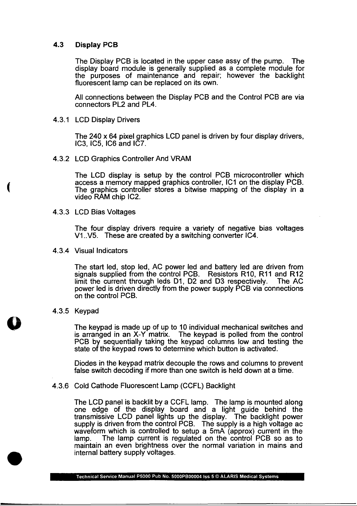
4.3
Display
The
display
the
fluorescent
All
connectors
PCB
Display
board
purposes
lamp
connections
PL2
PCB
module
of
between
and
is
located
is
generally
maintenance
can
be
replaced
the
PL4.
in
the
upper case
and
on
Display
supplied
repair;
its
own.
PCB
and
assy
of
the
as a complete
however
the
Control
the
pump.
module
backlight
PCB
are
The
for
via
4.3.1
4.3.2
4.3.3
4.3.4
LCD
The
103,
LCD
The
Display
240 x 64
105,
Graphics
LCD
Drivers
pixel
106
300
Controller
display
access a memory
The
graphics
video
LCD
The
RAM
Bias
four
V1..V5.
Visual
The
signals
limit
power
on
Indicators
start
the
led
the
control
supplied
controller
chip
Voltages
display
These
led,
stop
current
is
driven
PCB.
graphics
LCD
panel
is
107.
And
VRAM
is
setup
mapped
by
the
control
graphics
controller,
stores a bitwise
IC2.
drivers require a variety
are
created
led,
from
the
through
directly
by a switching
AC
power
control
leds
from
PCB.
D1,
the
led
and
D2
and
power
driven
PCB
by
microcontroller
IC1
mapping
of
negative
converter
battery
Resistors
D3
respectively.
supply
PCB
four
on
the
of
IC4.
led
R10,
display
display
the
display
bias
are
driven
R11
and
via
connections
drivers,
which
PCB.
in
a
voltages
from
R12
The
AC
4.3.5
4.3.6
Keypad
The
keypad
is
arranged
PCB
by
sequentially
state
of
the
Diodes
false
Cold
The
one
transmissive
supply
waveform
lamp.
maintain
internal
Technical
in
the
switch
Cathode
LCD
panel
edge
is
driven
which
The
an
battery
Service
is
made
in
an
X-Y
keypad
rows
keypad
decoding
Fluorescent
is
backlit
of
the
display
LCD
panel
from
is
controlled
lamp
even
Manual
current
brightness
supply
P5000
up
of
up
matrix.
taking
to
determine
matrix
if
decouple
more
Lamp
by a CCFL
lights
the
control
is
voltages.
Pub
No.
to
10
individual
The
keypad
the
keypad
than
one
(CCFL)
lamp.
board
up
and
the
PCB.
to
setup a 5mA
regulated
over
the
5000PB00004
columns
which
the
button
rows
switch
Backlight
The
a
display.
The
supply
on
the
normal
Iss 5 ©
mechanical
is
polled
from
low
is
activated.
and
columns
is
held
down
lamp
is
light
guide
The
is a high
(approx)
control
variation
ALARIS
Medical
switches
the
and
testing
to
prevent
at a time.
mounted
behind
backlight
voltage
current
PCB
in
mains
Systems
so as
and
control
the
along
the
power
ac
in
the
to
and
Page 49

4.4
Flexible
Circuit
4.4.1
4.4.2
4.4.3
Refer
Two
transmission
All
made
Motor
Two
to
Wiring
flexible
connections
via
circuits
components
PL1.
Optical
slotted
motor/gearbox
The
optical
shaft
End
of
A
slotted
of
switches
the
motor.
Infusion
optical
detect a near
mounted
Linear
A
slotted
used
the
unit.
on
the
Speed
optical
in
conjunction
Diagram
are
between
Encoders
optical
switches
assembly
are
Optical
switch
end
Switch
is
of
infusion. _ It
transmission
Optical
Switch
switch
is
with a slotted
Drg.
No.
5000EL00042
used
to
to
located
the
flexible
detect
make
in
are
activated
mounted
carriage.
mounted
all
the
upper
circuit
mounted
the
speed
by a flag
on
the
transmission
is
activated
on
the
transmission
grid
to
in
section
the
interconnections
case
assembly.
and
the
control
on
the
of
rotation.
mounted
on
the
by a flag
carriage
monitor
the
linear
5.
back
rear
motor
to
the
PCB
of
are
the
output
plate
which
and
travel
to
is
is
of
4.4.4
4.4.5
Transmission
A
micro
detect
Plunger
A
body
when
Detect
slotted
and
connected
Disengaged
switch,
the
optical
is
used
to
the
when a syringe
Microswitch
SW1,
is
transmission
Optical
switch
plunger
plunger
Switch
is
mounted
in
conjunction
detection
is
correctly
mounted
drive
on
the
transmission
has
been
disengaged.
inside
with a cruciform
button.
located
the
The
in
the
syringe
optical
plunger
carriage
plunger
actuator,
switch
holder.
to
holder
in
turn
detects
(
Technical
Service
Manual
P5000
Pub
No.
5000PB00004
Iss 5 ©
ALARIS
Medical
Systems
Page 50
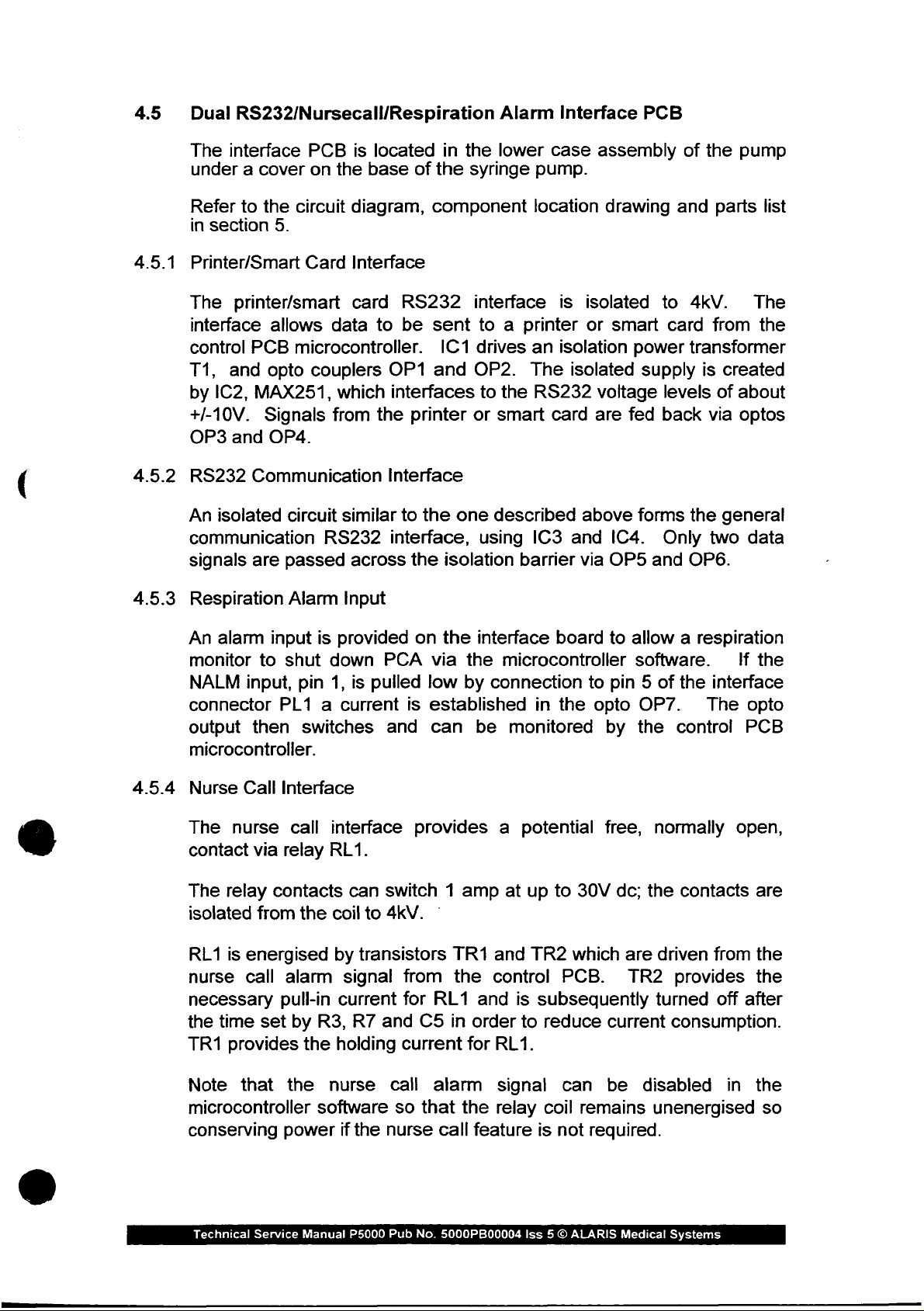
4.5
Dual
RS232/Nursecall/Respiration
The
interface
under a cover
PCB
on
is
the
located
base
of
in
the
Alarm
the
lower
syringe
Interface
case
pump.
PCB
assembly
of
the
pump
4.5.1
4.5.2
4.5.3
Refer
in
Printer/Smart
The
interface
control
T1,
by
+/-10V.
OP3
RS232
An
communication
signals
Respiration
An
monitor
NALM
connector
output
microcontroller.
to
the
section
5.
printer/smart
allows
PCB
and
opto
IC2,
MAX251,
Signals
and
OP4.
Communication
isolated
alarm
are
input
to
circuit
passed
Alarm
shut
input,
PL1 a current
then
circuit
Card
microcontroller.
couplers
is
pin
switches
diagram,
Interface
card
data
to
which
from
the
similar
RS232
across
Input
provided
down
1,
is
pulled
component
RS232
be
sent
IC1
OP1
and
interfaces
printer
Interface
to
the
one
interface,
the
isolation
on
the
PCA
via
the
low
by
is
established
and
can
location
interface
is
to a printer
drives
OP2.
to
or
using
interface
an
isolation
The
the
RS232
smart
described
card
IC3
barrier
board
isolated
and
via
microcontroller
connection
in
the
be
monitored
drawing
isolated
or
smart
power
voltage
are
fed
above
forms
IC4.
OP5
to
allow a respiration
software.
to
pin 5 of
opto
OP7.
by
the
and
to
4kV.
card
transformer
supply
levels
back
the
Only
and
OP6.
the
control
parts
from
is
via
two
list
The
the
created
of
about
optos
general
data
If
the
interface
The
opto
PCB
4.5.4
Nurse
The
contact
The
isolated
RL1
nurse
necessary
the
TR1
Note
microcontroller
conserving
Technical
Call
Interface
nurse
via
relay
contacts
from
is
energised
call
pull-in
time
set
provides
that
Service
call
relay
the
alarm
by
R3,
the
the
software
power
Manual
interface
RL1.
can
switch 1 amp
coil
to
4kV.
by
transistors
signal
current
R7
holding
nurse
from
for
and
current
call
so
if
the
nurse
P5000
Pub
provides a potential
at
up
to
30V
|
TR1
and
TR2
which
the
RL1
C5
in
alarm
that
call
No.
5000PB00004
control
and
order
for
RL1.
signal
the
relay
feature
PCB.
is
subsequently
to
reduce
can
coil
remains
is
not
required.
Iss 5 ©
ALARIS
free,
dc;
are
the
normally
driven
TR2
turned
current
be
disabled
unenergised
Medical
open,
contacts
provides
from
off
after
are
the
the
consumption.
in
the
so
Systems
Page 51

5.0
ELECTRICAL
PARTS
LISTS
SCHEMATICS,
COMPONENT
LOCATIONS,
AND
5.1
Electrical
5000EL00053
Block
Block
See
Diagram:
Diagram
next
sheet.
(not
issue
controlled)
Technical
Service
Manual
P5000
Pub.
No.
5000PB00004
ISS. 5 ©
ALARIS
Medical
Systems
Page 52

DISPLAY
NURSE
CALL
INTERFACE
RESP.
ALARM
INTERFACE
SUPERVISO
BATTERY
CHARGER
MEMORY
(RAM)
POWER
PERVISOR
MAINS
POWER
|
BATTERY
BACKUP
—
ev
JRATTERY
TIME
CLOCK
POWER
POWER
KEY
SWITCH
NEO!
SENSOR
LEDS,
START,
STOP
BATTERY
KEYPAD
| |
MICROCONTROLLER
+
GROUP
1C5,1C7,1C15,1C9
SYRINGE
SIZE
SENSOR
PRINTER
INTERFACE
WATCHDOG
MOTOR
ENCODER
(LEADING
MOTOR
ENCODER
LAGGING
SPEED
SENSOR
INTERFACE
AMP
GAIN
OFFSET
OCCLUSION
SENSOR
|
CURRENT
SENSOR
MOTOR
ENCODERS
POWER
LOW
BATTERY
SENSOR
COMMS
RS232
RS485
g
|
OR
MOTOR
DRIVE
ENABLE!
MOTOR
DRIVE
+Ve
MOTOR
DRIVE
Ve
—İ-
Technical
Service
(not
Manual
Electrical
issue
P5000
controlled)
Pub.
No.
Block
5000PB00004
Diagram
5000EL00053
ISS. 5 O
ALARIS
Medical
Systems
Page 53
5.2
Wiring
Diagram:
5000EL00042
Block
See
next
Diagram
sheet.
(not
issue
controlled)
Technical
Service
Manual
P5000
Pub.
No.
5000PB00004
ISS. 5 ©
ALARIS
Medical
Systems
Page 54

UPPER
BEA
10005P00603
CASE
ASSEMBLY
SYRINGE
POTENTIOMETER
1000SP01017
CONTROL
1000SP01007 \ E
dE
o]
PLUNGER
DETECT
SIZING
PL4
PLE]
PL7
PCB
OPTO
|
co
7
|
MOTOR
ENCODER
o
J3 品
ριο]
PL2
<
OPTOS
=
=>
1000SP01040
DECLUTCH
pov
|
,
Q
PL2
BLACK
|.
MOTOR/GEARBOX
NOTE
3
E]
っ 回 SPEED
HE
BACKLIGHT
DISPLAY
ASSEMBLY
MOTOR
POLARITIES
ARE
CORRECT
JLINEAR
rere
END
PCB
AS
SHOWN.
MARKED
OF
TRAVEL
OPTO
PL4
IN
50003200001
EX
б\
50005200002
to
0
No
У
Pro PLS
PL4
PL6
10005201005
POWER
BL
PL1
BN
LOWER
CASE
AUDIBLE
ALARM
SUPPLY
ASSEMBLY
Technical
PCB
PL3
BLACK
Service
|
(not
Manual
| |
ch
PL2
-
一
issue
P5000
COMMS
Wiring
controlled)
Pub.
BATTERY
No.
PCB
Diagram
5000PB00004
7
PL1
ーーー
PL3
Ba
10005P01003
+
5000EL00042
ISS. 5 ©
ALARIS
ct
Medical
ть.
让
Systems
JHANOSET
2
e
==)
.
Page 55

5.3
Power
Supply
Board
(MK
1):
5000EL00014
5000EL00002
5000EL00038
5000EL00039
Mark 1 Power
started
See
from
next
sheets.
Board
build
Component
PSU
BOM
BOM
superseded
issue
46.
Location
Schematic
240/220v
120/110v
at
build
Board
Board
issue
(not
issue
(not
issue
(MK1)
(MK1)
45.
(not
(not
Mark 2 Power
controlled)
controlled)
issue
issue controlled)
controlled)
Board
Technical
Service
Manual
P5000
Pub.
No.
5000PB00004
ISS. 5 ©
ALARIS
Medical
Systems
Page 56
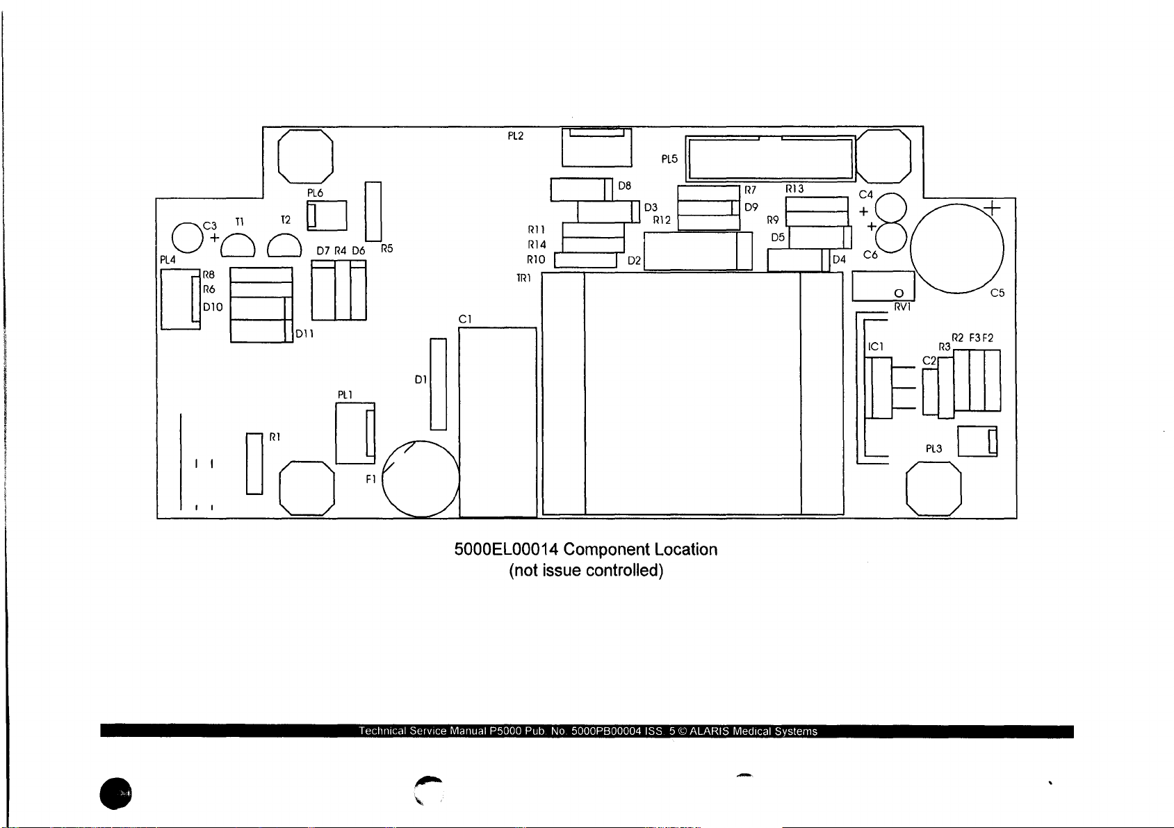
сз
O
PLA
R8
R6
D10
D8
|
p2
D3
R12
PLS
R7
D9
R13
R9
Ds
|
、
C4
A T
|
pa
©6
ICI
|
ο
RVI
|
PL3
Ze
R2
R3
C5
F3F2
RI
12
PL6
D7
R4
PL]
D6
RS
FI
DI
CI
53
PL2
TR)
VM
| | |
-
Ria
RIO
|
| |
Technical
Service
5000EL00014
(not
Manual
P5000
9
issue
Pub.
No.
Component
controlled)
5000PB00004
Location
ISS. 5 ©
ALARIS
Medical
Systems
Page 57
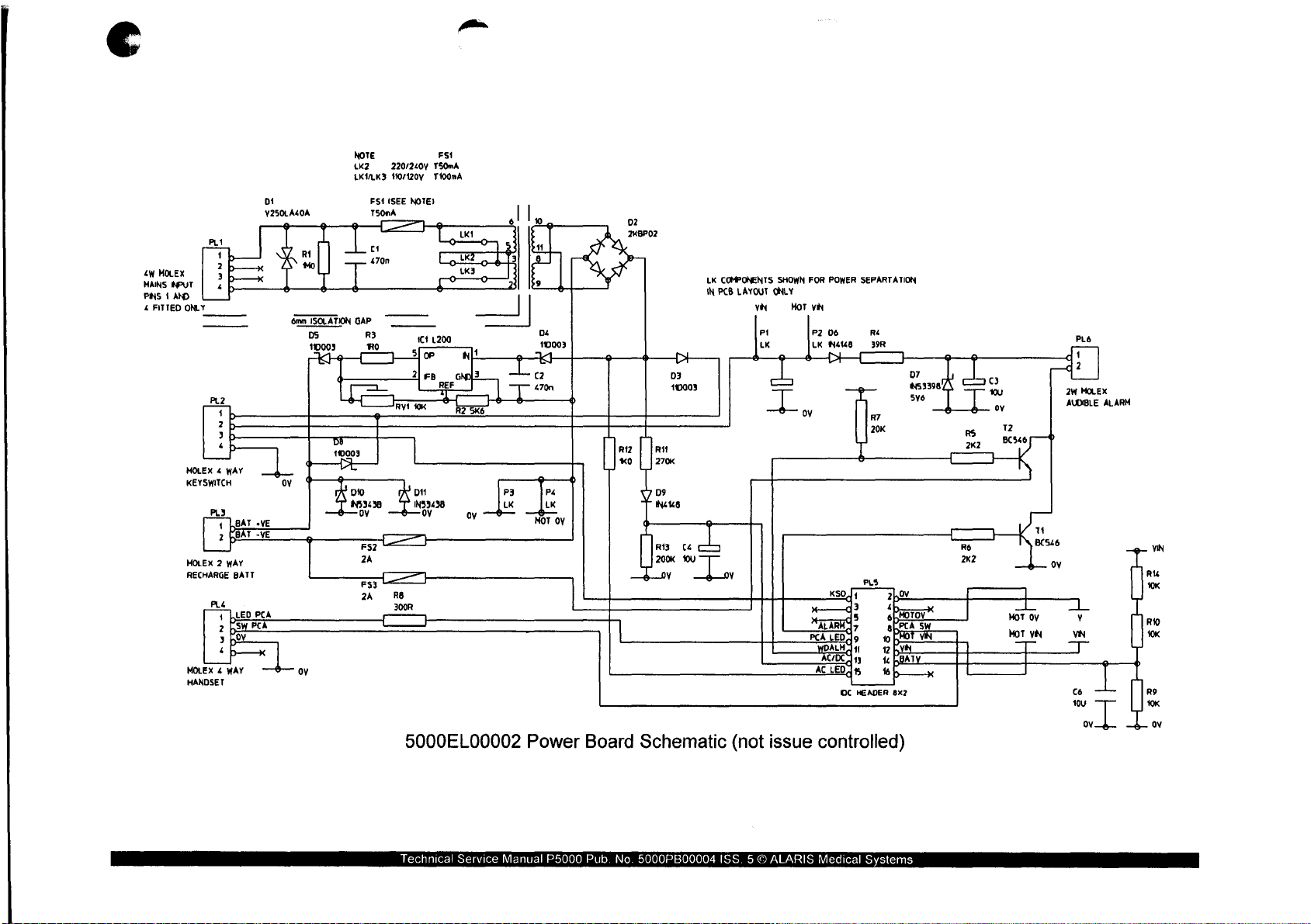
tu
MOLEX
MANS
eur
PINS 1 AND
4
FITTED
PL!
р
ONLY
PL2
|
MOLEX 4 WAY
KEYSWITCH
PL3
BAT
BÁT
MOLEX 2 WAY
RECHARGE
BATT
MOLEX 4 WAY
HANDSET
DI
V250LA4OA
_¿4
оу
«VE
-VE
”一
6mm
ISOLATION
DS
110003
+
|
4
oy
NOTE
tK2
LKILK3
©
GAP
一
Ἶ
DI
mel
DIO
53438
ov
ESA
T50nA
R3
Ro
=>
2A
FS3
2A
220/240
110/1207
(SEE
AVIR
=
Re
3008
一
로
Т50тА
T400mA
NOTE)
1
1200
2]
тв
RE
|
оч
IN53438
ov
一
FSI
REF
q
603
ta
и
| |
ο)
9
PI
|
D4
110003
K
cz
470n
Pá
LK
προ
|
Y
4
Gy
——
Ju
02
2KBP02
一
[> 一 一
D3
410003
[ls
D9
NUS
o
eL
200K
Wu
у
LK
COMPONENTS
IN
PCB
LAYOUT
YN
SHOWN
ONLY
e
|
у
一 一 wp
し
FOR
MOT
PCA
ADJm
POWER
VN
06
P2
LK
NB
KSO | 1
メーーーd3
ALARM
a
LED
ACLEDÍsS
OC
SEFARTATION
Ré
ŞOR
m
5
17
9
oby
1
py
fbBATY
tb
HEADER
2
pov
102
ob
Moroy
AEPCA
POT
8x2
S
vi
24
MOLEX
ALAR
>
AUDIBLE
a
!
|
|
x
MOT
MoT
一
Oy
VN
一
v
VN
|
cé
au
οκ
RIO
OK
o
R9
5000EL00002
Technical
Service
Power
Manual
P5000
Board
Pub.
No.
Schematic
5000PB00004
(not
ISS. 5 ©
issue
ALARIS
controlled)
Medical
Systems
Page 58

Item
Number:
Part
Number
5000PR00001
5000EL00011
0000ME00015
0000ME00292
0000EL00024
0000ME00228
0000ME00221
0000ME00126
0000ME00044
0000EL00031
0000EL00077
0000EL00054
0000EL00266
0000EL00018
0000EL00162
0000EL00014
0000EL00017
0000EL00016
0000EL00161
00006 ㄴ 00026
0000EL00284
0000EL00287
0000EL00023
0000EL00100
0000EL00012
0000EL00013
0000EL00011
0000EL00043
0000EL00041
0000ELOO037
0000ELOO038
0000ELOO034
0000EL00033
0000EL00256
0000ELO0036
ΟΟΟΟΕΙ
00040
0000EL00160
0000EL00255
0000EL00044
0000ME00115
0000ELO0306
,
0000EL00019
13.8.3
“Bill
5000EL00038
Reference
1
2
3
5
6
7
8
9
C1
C2
C3,4,6
C5
D1
D10,11
D2
D3,4,5,8
06,9
D7
F1
F2,3
FS1
IC1
LINK
1
PL1.2.4
PL3,6
PLS
R1
R11
R12
R13
R2
RI
R4
RS5.6
R7
R8
R9,10,14
RVI
SP1,2,3,4
TR1
TR1,2
of
Materials
ASSY
Print
PCB
PSU
Description
SCHEDULE
OUTLINE
PSU
WASHER
M3
NUT
M3
A2
HEATSINK
SCREW
M3x20
SCREW
M3x6
SPACER
M3x9.53
WASHER
M3
CAPACITOR
CAPACITOR
CAPACITOR
CAPACITOR
SUPPRESSOR
DIODE
1N5343B
RECTIFIER
DIODE 11DQ03
DIODE
IN4148
DIODE
1N5339B
HOLDER
FUSE
LINK
FUSE
FUSE 63mA
REGULATOR
CABLE
BLACK
CONNECTOR
CONNECTOR
CONNECTOR
RESISTOR
RESISTOR
RESISTOR
RESISTOR
RESISTOR
RESISTOR
RESISTOR
RESISTOR
RESISTOR
RESISTOR
RESISTOR
POTENTIOMETER
SPACER
TRANSFORMER
TRANSISTOR
2K2
20K
220R
4.8mm
ALARIS
240V
TEST
P5000
P5000
WAVEY
STAINLESS
PAN
PAN
HEX
NYLON
470n
250V
470n
50 V CERAMIC
10u
16V
3300uF
V250LA40A
ZENER
BRIDGE
ZENER
20MM
2A
PICOFUSE
20mm
A/S
L200
7/0.2
PLUG 4 WWAY
PLUG 2 WAY
PLUG
1MO
0.5W
270K
0.25W
1K0
0.25W
200K
0.25W
SK6
0.25W
1RO
0.25W
39R
0.25W
0.25W
0.25W
0.25W
10K
0.125W
10K
SELF
7.5V
BC546
MEDICAL
P5000
SST
STEE
HD
POSI 1 ZP+P
HD
POSI
ZP+P
NYLON
AC
X2
TANT
16V
ELECTROLYTIC
7V5
2KBP02
5V6
VERTICAL
ANTI-SURGE
MOLEX
MOLEX
16
WAY
HEADER
1%
1%
1% 10
1%
1%
1% 10
1%
1%
1%
1%
0.1%
METAL
25
TURNS
RETAINING
8VA
A0807/HF
L
Iss:
FILM
SYSTEMS
9
25
Qty
10
1.0
1.0
10
1.0
2.0
3.0
2.0
2.0
1.0
10
3.0
1.0
1.0
2.0
1.0
40
2.0
1.0
1.0
2.0
1.0
1.0
0.1
3.0
2.0
10
1.0
10
1.0
1.0
1.0
2.0
1.0
10
3.0
1.0
40
1.0
2.0
Technical
Service
Manual
P5000
Pub.
No.
5000PB00004
ISS. 5 ©
ALARIS
Medical
Systems
Page 59
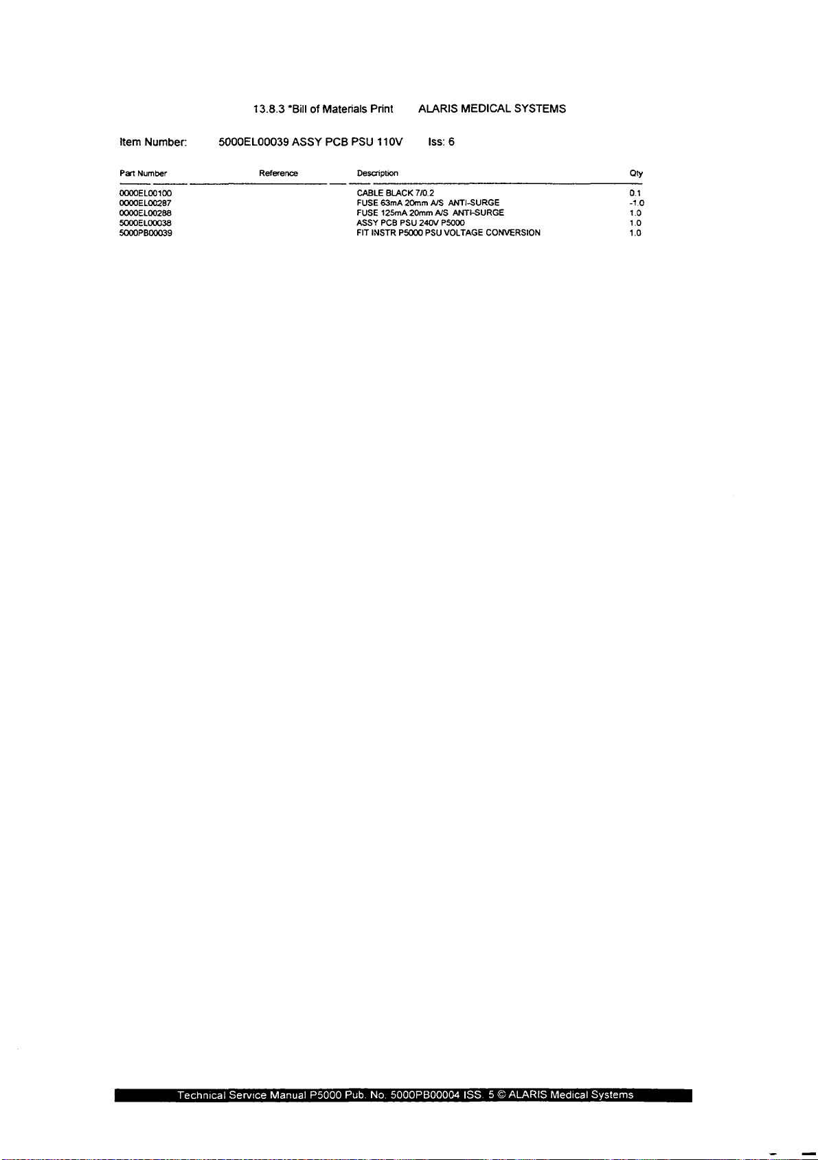
Item
Number:
Part
Number
0000EL00
0000EL00287
0000EL00288
5000EL00038
5000PB00039
100
5000Е1
13.8.3
00039
Reference
"Bill
of
ASSY
Materials
PCB
PSU
Description
CABLE
FUSE
FUSE
ASSY
FIT
Print
110V
BLACK
63mA
125mA
PCB
INSTR
ALARIS
Iss:
7/0.2
20mm
A/S
20mm
PSU
240V
P5000 PSU
6
ANTI-SURGE
A/S
ANTI-SURGE
P5000
VOLTAGE
MEDICAL
CONVERSION
SYSTEMS
Oty
0.1
-1.0
1.0
10
1.0
Technical
Service
Manual
P5000
Pub.
No.
5000PB00004
ISS. 5 ©
ALARIS
Medical
Systems
Page 60
5.3
Power
Supply
Board
(MK
2):
5000EL00059
5000EL00058
5000EL00060
5000EL
See
00061
next
sheets.
PSU
PSU
BOM
BOM
Schematic
Component
240/220v
120/110v
Location
Board
Board
(not
issue
(not
(MK2)
(MK2)
controlled)
issue
(not
(not
controlled)
issue
issue
controlled)
controlled)
Technical
Service
Manual
P5000
Pub.
No.
5000PB00004
ISS. 5 ©
ALARIS
Medical
Systems
Page 61
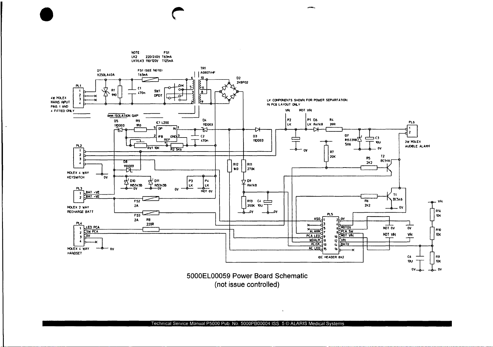
©
e
a
va
MA
INS
INPUT
PINS 1 AND
4
FITTED
ONLY
PL2
MOLEX 4 WAY
KEYSWITCH
PL3
MOLEX
RECHARGE
PL4
MOLEX 4 WAY 一 @ 一 oy
HANDSET
tb
2
b
3
b
‘
1LBAT。VE
2
BAT
-YE
P
WAY
2
BATT
4
LLED
PCA
Psy
PCA
Poy
:
р
4
ーーーX
DI
VZBOLA40A
6mm
ISOLATION
Ds
110003
」
do
ov
*
만
[과
NOTE
LK2
LKYLK3
DIO
NS
FS1
(SEE
T63nA
GAP
R3
180
<
3455
ov
ra
TI]
24
rs
가
24
[一 一 一
Lt
NOTE)
1C1
T63mA
T125mA
1.200
FSi
220/240Y
110/120V
Je
21 8 다 머 크
SF
10K
RVÍ
DIA
1NS949B
ov ον 一 全
RS
220R
、
5
3
1
9—
1
LST
296
PI
LK LK
5000EL00059
TRI
| |
AcsovHe
和
3
1
9
Ds
110003
cz
470n
À
P
P4
一 人
一
MOT
一
р
oy
(not
issue
D2
2KBP02
>
D3
110003
Riz
| |
매
xo | |
270«
DI
INZIZO
RO
200K
Y у
Power
Board
controlled)
ει
L
ου
COMPONENTS
LK
IN
PCB
LAYOUT
VIN
o
Schematic
SHOWN
ONLY
mat
MOT
POWER
FOR
VIN
Kso
randy
LED
PCA
CDE
AL
LED
SEPARTATION
PLS
[1
3
5
а?
OC
HEADER
가.
“basmaz
spero
aPPcA
S
yi
Ptor
10
[=
ор
чи
ВАТУ
κό
8x7
PLO
1
2W
MOLEX
ALARM
AUDIBLE
UN
“
|
x
L
MOT
MOT
一
]
L
ov ov
VN
一
—
VN
cé
toy
e
RO
10K
>
|
T
R9
10K
DY
Technical
Service
Manual
P5000
Pub.
No.
5000PB00004
ISS. 5 ©
ALARIS
Medical
Systems
Page 62

Η4
PLa
一
一
一
rx
He
Or
To
T
q
u
8
m
9
S S
이
ъ
op
84
Sé
8
©
|
|
O)
Dİ"
TI
M
PL6
Te
RE
RB
πο
tON
d3S
SSI
H
RS
R41
i
R10
TR1
230
415
F4
5000EL00058
(not
issued
|
Cass:
I
|
D8
|
De
D3
R12
|
Component
controlled)
Location
R7
R13
RI
mi
;
C4
+
KL
ο
=
sr
1C1
014 一 011
+
R3
Ce
Ord
#3
|
A
EE
4
+
[
|
|
Technical
Service
Manual
P5000
Pub.
No.
5000PB00004
ISS. 5 ©
ALARIS
Medical
Systems
Page 63

item
Number:
5000EL00060
13.8.3
ASSY
*Bill of
PCB
Materials
PSU
230V
Print
P5
(2)
ALARIS
iss:
8
MEDICAL
SYSTEMS
Assembly
1.
CUT
OFF
2.
RECORD
3.
ENSURE
4,
ALL
COMPONENT
STATED.
5.
FIT
C2 + TO
6.
CORNERS
TRANSFORMER
Part
Number
5000PR00001
5000EL00059
5000EL00058
0000ME00015
0000ME00292
0000ME00235
0000EL00024
0000ME00228
0000ME00221
0000ME00126
0000ME00044
0000ELOO031
0000Е1
00054
0000EL00054
0000EL00266
0000EL00018
0000EL00162
0000EL00014
0000EL00017
0000EL00016
0000EL00161
0000EL00026
0000EL00284
0000EL00287
0000EL00023
0000EL00100
0000EL00012
0000EL00013
0000EL00131
0000EL00011
0000EL00043
0000ELOO041
0000EL00037
0000EL00038
0000EL00034
0000EL00033
0000EL00256
0000EL00036
ΟΟΟΟΕΙ
00040
0000EL00160
0000EL00255
0000EL00044
0000ME00115
0000EL00351
0000EL00306
0000EL00019
Notes:
THE
THE
THAT
PIN 1 OF
OF
CORNER
ISSUE
SWITCH
LEADS
THE
TRANSFORMER
AND
LEAVE
FROM
TR1,
BOX
ON
POSITION
BE
CROPPED
CORNER
THE
240.
PCB
ADD
TO
IN
THE
IS IN
TO
IC1.
MUST
NO
SHARP
Reference
1
2
3
4
5
6
7
8
9
C1
cz
C3.4.6
cs
D1
D10,11
D2
D3,4,5,8
D6,9
D7
F1
F2,3
FS1
IC1
LINK
1
PL1,2
PL3,6
PL4
PL5
RI
R11
R12
R13
R2
R3
R4
R5,6
R7
R8 RESISTOR
R9,10,14
RV1
SP1,2,3,4
swt
TRI
TR1.2
BE
EDGES.
Description
SCHEDULE
SCHEMATIC
OUTLINE
WASHER
NUT
LABEL
HEATSINK
SCREW
SCREW
SPACER
WASHER
CAPACITOR
CAPACITOR
CAPACITOR
CAPACITOR
SUPPRESSOR
DIODE
RECTIFIER
DIODE
DIODE
DIODE
HOLDER
LINK
FUSE
REGULATOR
CABLE
CONNECTOR
CONNECTOR
CONNECTOR
CONNECTOR
RESISTOR
RESISTOR
RESISTOR
RESISTOR
RESISTOR
RESISTOR
RESISTOR
RESISTOR
RESISTOR
RESISTOR
POTENTIOMETER
SPACER
SWITCH
TRANSFORMER
TRANSISTOR
CLOSEST
IDENT.
ITEM 4 ACROSS
WITHIN
TRIMMED
TEST
P5000
PSU
M3
WAVEY
M3
A2
STAINLESS
240V
SELF
M3x20
M3x6
M3x9.53
M3
NYLON
470n
10u
10u
3300uF
1N5343B
BRIDGE
11DQ03
IN4148
1N5339B
FUSE
FUSE
2A
63mA
20mm
L200
BLACK
PLUG 4 WAY
PLUG 2 WAY
PLUG 3 WAY MOLEX
PLUG
1M0
270K
1K0
200K
5K6
1RO
39R
2K2
20K
220R
10K
4.8mm
SLIDE
BC546
TO
1mm
TO
P5000
PSU
P5
(2)
ADHESIVE
PAN
HD
PAN
HD
HEX
250V
16V
TANT
16V
TANT
16V
V250LA40A
ZENER
2KBP02
ZENER
20MM
PICOFUSE
A/S
7/0.2
16
0.5W
1%
0.25W
0.25W
0.25W
0.25W
0.25W
0.25W
0.25W
0.25W
0.25W
0.125W
10K
SELF
115/230V
7.5V
BVA
PL3,
OF
WITHIN
PCB
SST
STEEL
POSI 1 ZP+P
POSI
ZP+P
NYLON
AC
X2
ELECTROLYTIC
7V5
5V6
VERTICAL
ANTI-SURGE
MOLEX
MOLEX
WAY
HEADER
1%
1%
1%
1%
1%
1%
1%
1%
1%
0.1%
METAL
25
TURNS
RETAINING
ARCOELECTRIC
A0807/HF
IC1AND
THE
THE
1mm
FIXING
240V
BOARD
FILM
INDICATOR.
UNLESS
OF
THE
25
X2225C
SCREW.
BODY
OTHERWISE
OF
THE
Qty
1.0
1.0
1.0
10
1.0
1.0
10
2.0
3.0
2.0
20
1.0
10
3.0
10
1.0
20
10
40
20
1.0
1.0
2.0
10
1.0
0.1
2.0
2.0
1.0
1.0
1.0
10
1.0
1.0
1.0
1.0
1.0
20
1.0
1.0
3.0
1.0
4.0
1.0
10
2.0
Technical
Service
Manual
P5000
Pub.
No.
5000PB00004
ISS. 5 ©
ALARIS
Medical
Systems
Page 64
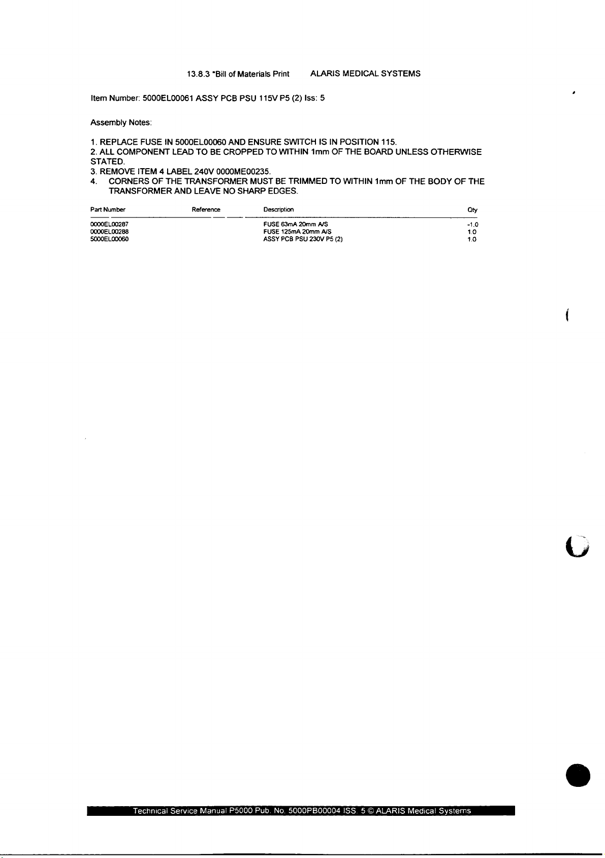
Item
Number:
5000EL00061
13.8.3
ASSY
*Bill
of
PCB
Materials
PSU
115V
Print
P5
(2)
ALARIS
Iss:
5
MEDICAL
SYSTEMS
Assembly
1.
REPLACE
2.
ALL
COMPONENT
STATED.
3.
REMOVE
4.
CORNERS
TRANSFORMER
Part
Number
0000EL00287
0000EL
00288
5000EL00060
Notes:
FUSE
IN
ITEM 4 LABEL
OF
THE
5000EL00060
LEAD
TO
240V
TRANSFORMER
AND
LEAVE
Reference
AND
BE
ENSURE
CROPPED
0000ME00235.
NO
SHARP
TO
MUST
Description
FUSE
FUSE
ASSY
SWITCH
WITHIN
BE
TRIMMED
EDGES.
63mA
125mA
PCB PSU
20mm
20mm
1mm
230V
IS
A/S
A/S
PS
IN
OF
TO
(2)
POSITION
THE
BOARD
WITHIN
115.
1mm
UNLESS
OF
THE
OTHERWISE
BODY
OF
THE
Qty
-10
10
10
Technical
Service
Manual
P5000
Pub.
No.
5000PB00004
ISS. 5 ©
ALARIS
Medical
Systems
Page 65

5.4
Control
Board
(mark
1):
5000EL00004
5000EL00001
5000EL00010
Mark 1 has
See
next
same
sheets.
Component
Control
Control
Component
Location
Board
Schematic
BOM
Location
Board
as
Mark
(not
(not
(not
2.
issue
issue
issue
controlled)
controlled)
controlled)
Technical
Service
Manual
P5000
Pub.
No.
5000PB00004
ISS. 5 ©
ALARIS
Medical
Systems
Page 66

c13
ΤΙ
ov
ха
12.000MHz
İT
|
VCC ㅡ 990
6590 | CER-
oie
OSC
IN
PFO
OSC_SEt
PRI
48
474645
44
5000EL00001
hnical
Service
Manual
Bye
Riw
DS
WE
RŠ
959
(not
P5000
Pub.
cs
H8/536
84W
SOCKET
__TB_I
Control
issue
No.
Е
Board
controlled)
5000PB00004
Schematic
ISS.
50
ALARIS
Medical
Systems
30 29
5
9
28
ES
Page 67

TRIO
BC846
R69
2K2
R67
SYRINGE
R23
10K
2K2
R68
20K
BC846
SIZING
ZTX751
TR9
4
R25
Bae
G
AMP
AVCC
ZTxBŠÍ
R24
10K
R30
TR
TURNED
TR7
ZTX751
11
13
10
12
14
3
MLX
PIN
SKT
ca)
R17
190p
BEAM
200K
STRAIN
GAUGE
AMPLIFIER
AVC
VIN
P1
LK
STAR
HEATSINK
18
ıç
LMZ2940TS
væ
PZ
|
SS
FGNDA
GROUNDS
WP
1
P3
LK LK
STAR
AREER
mc
26 ς27
100.
о7
4NS339B
5V6
P4
Nois:
shown
Re
dh
10412
25V
REAR
Lo
58
у
1N533
ак.
'LK's
ore
for
PCB
REF
C42
του
ic
12
dummy
layout
20mm
て
R26
10K
06
LT1009CZ
AGND
16/02
PLA
FGND
componente
purposes
3mm
WIRE
TA
HOLE
G
Technical
5000EL00001
Service
Manual
P5000
(not
Pub.
1314
Control
issue
controlled)
No.
5000PB00004
Board
Schematic
ISS. 5 ©
ALARIS
Medical
Systems
Page 68
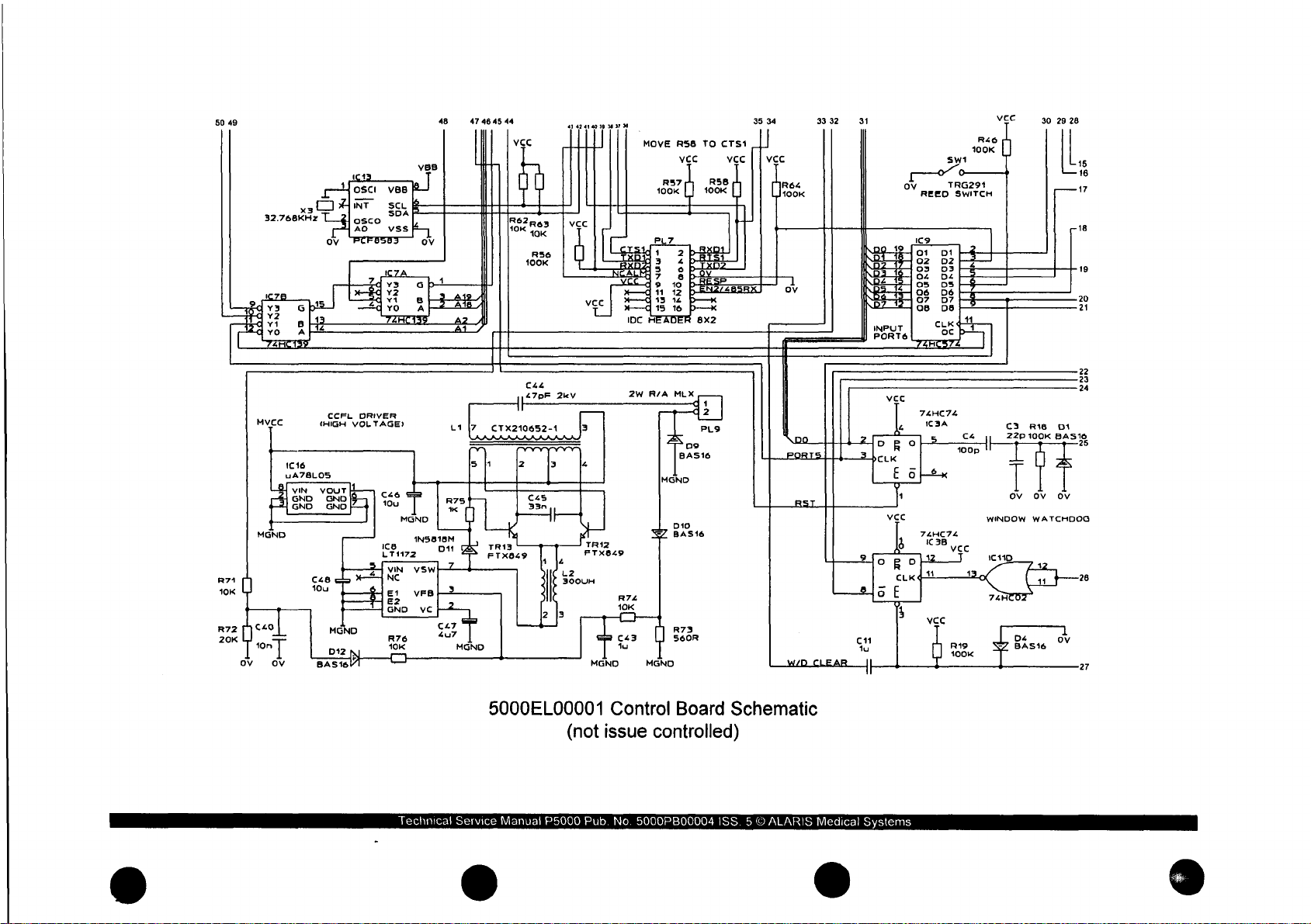
50 49 48
32.768KHz
x3
OSCI
INT
osco
AO
VBB
SCL
SDA
vss
47
46 45 44 35
MOVE
R56
TO
CTS1
c c
34
R46
100K
SWI
ον
TRG291
REEO
SWITCH
30
29
28
16
17
20
a
R71
10K
1016
uA7BLOS
VIN,
(HIGH
VOUT
R72
20K
CCFL
DRIVER
VOLTAGE?
ice
LT1172
VIN
NC
El
E2
GND
R76
10K
1N5818M
VSW
VEB
vc
on
407
C44
47pF
CTX210652-1
TR1
3
FTX849
5000EL00001
2kV
L2
300UH
(not
TRIZ
FTXOL9
Control
issue
2W
R/A
MLX
Board
controlled)
Schematic
ORO
CLK
E
74HC74
1C
a
<
74HC74
IC3B
3A C3
22p
ον ον
WINDOW
R18
D1
100K
BASI
ον
WATCHDOG
22
24
26
27
Technical
Service
Manual
P5000
Pub.
No.
5000PB00004
ISS. 5 ©
ALARIS
Medical
Systems
Page 69
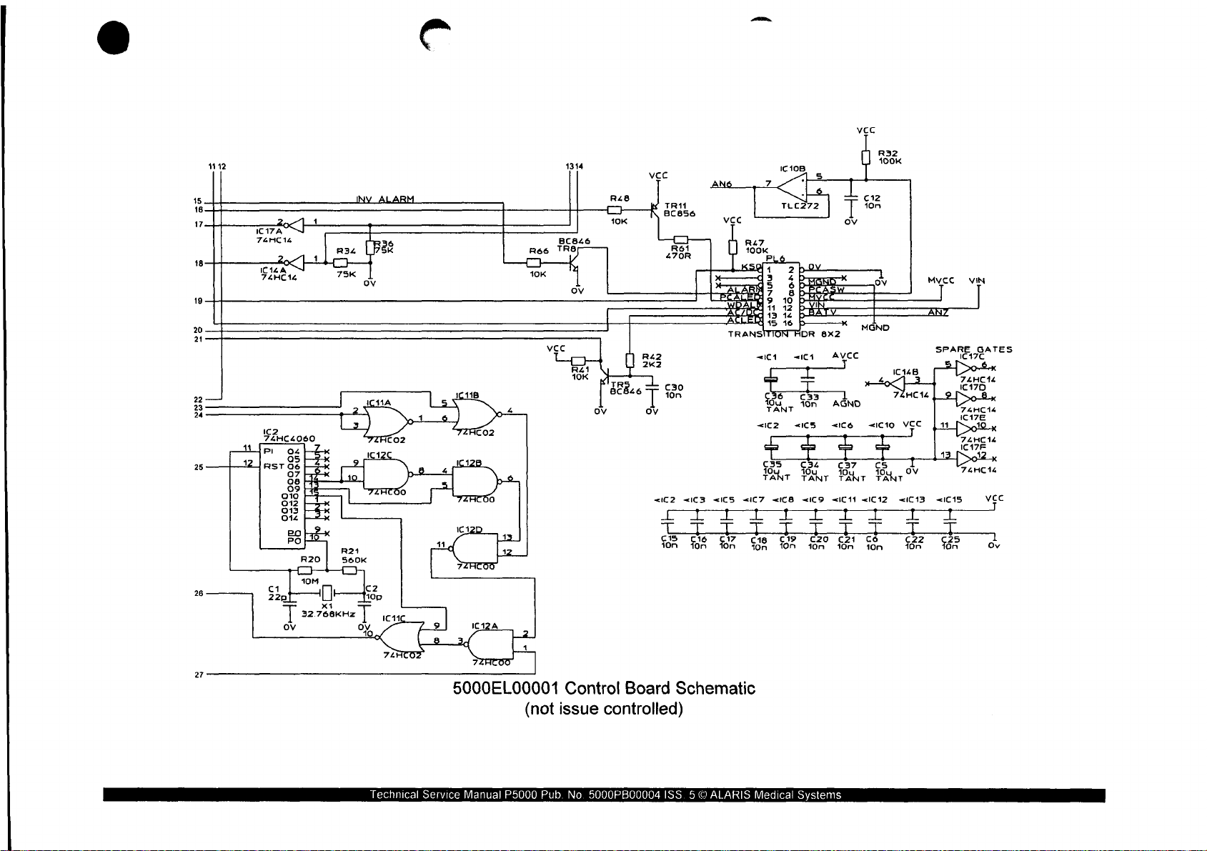
2
15
18
17
18
19
20
С
17А
THC
IC16A
74HC14
—
NY
ALARM
R47
100K
PATH?
ACD
At
TRANSITION
<ICS
«IC7
VV
Е
On
<IC1
636
<IC2
Dod
a.
TANT
그
ci
508
р
4
3
5
7
10
14
12
13
16
0
TANT
<ICB
그
19
On
2b2v.
4
Sp
BP
PU
р
ADR
<1 ㄷ 1
csa
On
«ICS
в
T
<ICD
VV
C20
fon
w
8x2
AVCC
AGNO
«ιδ
do
0
Ca
An
>, z = + >
<IC11
FF
C21
100
[``
MGND
<ic10
1
==
u N n
4 + >
<IC12
TT
Cé
10n
1
—
IC14B
Ha
I
un
r
<IC13
т
мусс
АНУ
|
HC
14
==
VEC
+4
ον
22 25
On
SPARE
dot
İm
13.
<IC15
L
On
VIN
GATES
IC17C
74HC14
IC17D
>o-Ex
74HC14
iC17E
1
74HC
12
1C17F
74HC14
Усс
6
9
2.
2
OC
1
14
1
pu
R34
73K
I
6
ae
ov
Ree
TOK
TRE
ov
Beh
|
J
Xx]
<tC2
cs
100
<IC3
그
On
СФ
a
Technical
5000EL00001
Service
Manual
4
|]
(not
P5000
Control
issue
Pub.
No.
Board
controlled)
5000PB00004
Schematic
ISS. 5 ©
ALARIS
Medical
Systems
Page 70

Item
Number:
5000EL00010
13.8.3
ASSY
*Bill
of
PCB
Materials
CONTROL
Print
PCAM
ALARIS
Iss:
5
MEDICAL
SYSTEMS
Assembly
1.
FIT
Y1+Y3
2.
FIT
B1,PL2,PL4,PL6,SW1
3.
FIT
PL2+PL4
TIGHT
AGAINST
4.
FIT
PL6
§.
CRIMP A LENGHT
6.
FIT
ITM 1 INTO
7.
USE
ITM5,6,7
WASHER
8.
FIT
SW1
CONTACT
PCB),
THE
END
OF
9.
1C20.
Part
5000PR00005
0000EL00208
0000EL00232
0000EL00270
0000EL00230
0000EL00030
ΟΟΟΟΕΙ
0000EL00272
0000EL00273
0000EL00276
0000EL00278
0000EL00229
0000EL00230
0000EL00234
0000EL00235
0000EL00274
0000EL00236
0000EL00206
0000EL00237
0000EL00209
0000EL00217
0000EL00218
0000EL00219
0000EL00220
0000EL00221
0000EL00223
0000EL00222
0000EL00221
0000EL00224
0000EL00269
0000EL00210
0000EL00211
0000EL00212
0000EL00083
D000EL00214
0000EL00264
ΟΟΟΟΕΙ
0000EL00216
0000ME00115
5000ME00069
0000EL00182
0000EL00261
0000ME00070
0000ME00292
0000ME00015
0000EL00012
0000EL00131
0000EL00189
0000EL00279
0000EL00280
5000EL00005
0000EL00262
0000EL00228
0000EL00104
0000EL00123
0000EL00011
0000EL00147
0000EL00239
0000EL00240
0000EL00231
0000EL00271
0000EL00247
0000EL00248
THE
PROGRAM
EPROM
Number
00233
00268
Notes:
FLAT
ON
THE
TRANSITION
THE 5 HOLES
TO
ON
TOP
OF
TO
NON
INSIDE
GLASS
GLASS
RECESS.
BLANK
MUST
ON
PCB,HAND
THE
NON
SURFACE
HEADER
OF
ITEM 3 TO
FIX
ITM4
IC18.ENSURE
COMP
IS
BODY
IS
EPROM
BE
APPROPRIATELY
Reference
B1
C1,3,7,13
C2
C22,24,25,27
C26
C4,38,39,50,
(43
C44
C45
C47
C5,14,23,32,
C6,10,12,15,
C8,9,11
D1,4,5,9,10,
D11
D6
07.8
D7,8
IC1
IC10
1C11
IC12
1613
1614
iC15
IC1S-ALTERN'
IC17
IC18
1C19
IC2
IC3
IC4
ICS
106
IC7
Ics
Ico
ITM1
ITM2
ITM3
ITM4
ITMS
TTM6
ITM7
J1
3
J8
LI
12
PCB
PL2
PL4
PLS
РАБ
PL7
PL9
R1
R2,4,11
R20
R21
R22,25,51,54
R23,24,26,30
AND
ITEM 1 AS
COMP
OF
WITH
AROUND
BENEATH
SIDE
OF
POLARISED
OFFSET
IC20
SOLDER
SIDE
THE
THE
J8,
SOLDER
HEATSINK
BOARD
TO
WITH
THE
POST
OF
BOARD.
PCB.
CABLE
THE
PCB,FIT
1C18.
FIT
WITH
AS
SHOWN
THE
‘CONTACT’ END
LATEST
LABELLED.
Description
SCHEDULE
BATTERY
CAPACITOR
CAPACITOR
CAPACITOR
CAPACITOR
CAPACITOR
CAPACITOR
CAPACITOR
CAPACITOR
CAPACITOR
CAPACITOR
CAPACITOR
CAPACITOR
DIODE
DIODE
DIODE
DIODE
DIODE
IC
TYPE
IC
TYPE
IC
TYPE
IC
TYPE
IC
TYPE
IC
TYPE
IC
TYPE
IC
TYPE
1C
TYPE
IC
TYPE
IC
TYPE
IC
TYPE
IC
TYPE
IC
TYPE
CONNECTOR
IC
TYPE
IC
TYPE
IC
TYPE
IC
TYPE
SPACER
SPACER
CABLE BLACK
HEATSINK
SCREW
NUT
WASHER
CONNECTOR
CONNECTOR
TERMINAL
COIL
INDUCTOR
OUTLINE
CONNECTOR
CONNECTOR
CONNECTOR
ASSY
CONNECTOR
CONNECTOR
RESISTOR
RESISTOR
RESISTOR
RESISTOR
RESISTOR
RESISTOR
END
OF
ASSEMBLY
ORIENATE
RUN
THE
OTHER
SCREW
IS
SQUARE
GLASS
IN
S/W
AS
TEST
NiCd
22p
10p
10n
100u
100p
1u
47p
33n 50v
4u7
10u
10n
1u
BAS16
IN5818M
GL41
S/M
IN53398
LT1009CZ
TLC274ACD
TLC272CD
74HC02
74HC00
PCF8583T
74HC14
74AC574D 8 BiT
74ACS74N 8 BIT
74HC14
LM2940CT-5.0
78L05
MC14060B
74HC74
HM62256BLFP-10T
SOCKET
MAX691A
74HC139
LT1172
74HC574 8 BIT
4.8mm
REED
P5
PSU
M3x8
PAN
M3
A2
STAINLESS
M3
WAVEY
PLUG 4 WAY
PLUG 3 WAY
CRIMP
CTX210652-1
300uH
CONTROL
PLUG
PLUG
SOCKET
CABLE
RIBBON
PLUG
PLUG 2 WAY
4K7
270K
10M
560K
470R
10K
CAN
TO
SECURE
IT
TO
THE
PCB.
OPERATIONS.
THE
CONNECTORS
OUT
OVER
THE
OF
THE
OUTLINE.
THE
RECESS
TO
CREATE
P5000
BARRIER
OP
AMP - TEXAS
AMP
TEXAS
GATE
SOIC
GATES
SOIC
SOIC
SOIC
RAM
32Kx8
WAY
REGULATOR
SVM
D
L
RING
(SAMTEC
(SAMTEC
HEADER
MOLEX
EDGE
WIRE
SIDE
SIDE
NEAREST
SO
S/M
SOIC
SOIC
SOIC
SOIC
MOTOROLA
SOIC
MAXIM
SOIC
S/M
BOL-111-T-E)
SDL-107-TT-11)
END
FROM
NON-COMP
INTO
NON-COMP
TO
IS
BODY
IDENT
IN
(CONTACT
OFRECESS,
SUPPLIED
CONTROL
2.4V
40mAH
50v
COG
1206
50V
COG
1206
25V
CERAMIC
ELECTR.
50V
1205
16v
TANT
2KV
CERAMIC
CERAMIC
16V
TANT C CASE
16V
TANT C CASE
25V
CERAMIC
16V
CERAMIC
S™
SCHOTTKY
SV6
ZENER
OUAD
DUAL
OP
QUAD
NOR
QUAD
NAND
RTC
CHIP
SCHMITT
SCHMITT
VOLTAGE
DUAL
SWITCHING
SELF
SWITCH
16/0.2
0.25W
0.25W
0.125W
0.25W
0.25W
0.25 13.0
INVERTER
LATCH
LATCH
INVERTER
REGULATOR
REGULATOR
CMOS
COUNTER
LATCH
IC
28
MICRO
SUPERVISOR
DUAL 2 TO 4 DECODER
LATCH
RETAINING
HD
SLOTTE
STEE
SST
MOLEX
MOLEX
INSULATED
CTX300-4
P5000
22
WAY
16
WAY
14
WAY
16
WAY
16
WAY
R/A
2%
2%
2%
OF
PCB.
TO
J8.
OF
BOARD
OF
OF
THE
GLASS
IC20-PROG,
SOIC
SOIC
SOIC
SO
PLASTIC
BOARD,
ITM
2.
THE
CORNER
NUT
ENSURE
TOUCHES
FIT
0.0
40
9.0
5.0
1.0
10
1.0
1.0
11.0
11.0
3.0
6.0
10
1.0
2.0
1.0
1.0
1.0
10
1.0
1.0
1.0
1.0
0.0
10
1.0
10
1.0
1.0
1.0
1.0
1.0
10
10
1.0
5.0
1.0
0.1
1.0
10
1.0
1.0
1.0
10
1.0
10
1.0
1.0
1.0
1.0
1.0
10
1.0
10
1.0
3.0
1.0
10
4.0
Qty
10
1.0
1.0
BODY
AND
INTO
IS
THAT
OF
THE
SKT-
Technical
Service
Manual
P5000
Pub.
No.
5000PB00004
ISS. 5 ©
ALARIS
Medical
Systems
Page 71
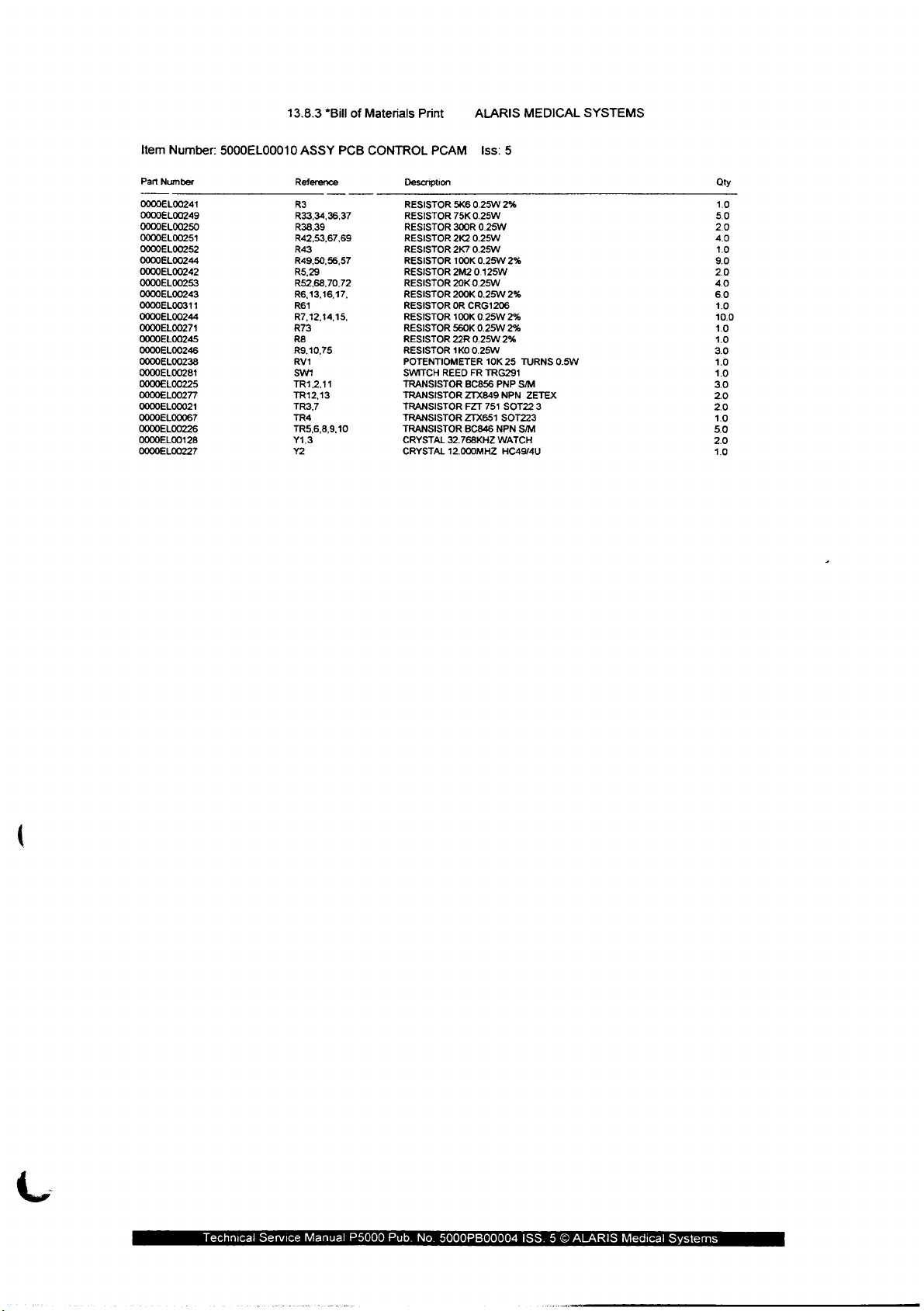
Item
Number:
Part
Number
0000EL00241
0000EL00249
0000EL00250
0000EL00251
0000EL00252
0000EL00244
0000EL00242
O0000EL
00253
0000EL00243
0000EL00311
0000EL00244
0000EL00271
0000EL00245
0000EL00246
0000EL00238
0000EL00281
0000EL00225
0000EL00277
0000EL00021
0000EL00067
0000EL00226
0000EL00128
0000EL00227
5000EL00010
13.8.3
*Bill
ASSY
PCB
Reference
R3
R33,34,36,37
R38,39
R42,53,67,69
R43
R49,50,56,57
R5,29
R52,68,70,72
R6,13,16,17,
R61
R7,12,14,15,
R73
88
R9,10,75
RV1
sm
TR1,2,11
TR12,13
TR3,7
TR4
TR5.6.8.9.10
Y1.3
Y2
of
Materials
CONTROL
Print
PCAM_
Description
RESISTOR
RESISTOR
RESISTOR
RESISTOR
RESISTOR
RESISTOR
RESISTOR
RESISTOR
RESISTOR
RESISTOR
RESISTOR
RESISTOR
RESISTOR
RESISTOR
POTENTIOMETER
SWITCH
REED
TRANSISTOR
TRANSISTOR
TRANSISTOR
TRANSISTOR
TRANSISTOR
CRYSTAL
32.768KHZ
CRYSTAL
12.000MHZ
ALARIS
5K6
0.25W
75K
0.25W
300R
2K2
0.25W
2K7
0.25W
100K
2M2
0.125W
20K
0.25W
200K
OR
CRG1206
100K
560K
22R
0.25W
1K0
0.25W
FR
BC856 PNP
ZTX849
FZT
ZTX651
BC846
Iss:
0.25W
0.25W
0.25W
0.25W
0.25W
10K
TRG291
751
5
2%
2%
2%
2%
2%
2%
25
NPN
SOT22
SOT223
NPN
WATCH
HC49/4U
MEDICAL
TURNS
S/M
ZETEX
3
S/M
0.5W
SYSTEMS
Qty
1.0
50
2.0
40
10
9.0
20
40
6.0
1.0
10.0
10
10
3.0
1.0
1.0
3.0
20
2.0
10
50
2.0
1.0
Technical
Service
Manual
P5000
Pub.
No.
5000PB00004
iSS. 5 ©
ALARIS
Medical
Systems
Page 72

5.4
Control
Board
(mark
2):
5000EL00056
5000EL00054
5000EL00055
See
next
sheets.
Component
Control
Control
Board
BOM
Location
Schematic
(not
(not
(not
issue
issue
issue
controlled)
controlled)
controlled)
Technical
Service
Manual
P5000
Pub.
No.
5000PB00004
ISS. 5 ©
ALARIS
Medical
Systems
Page 73
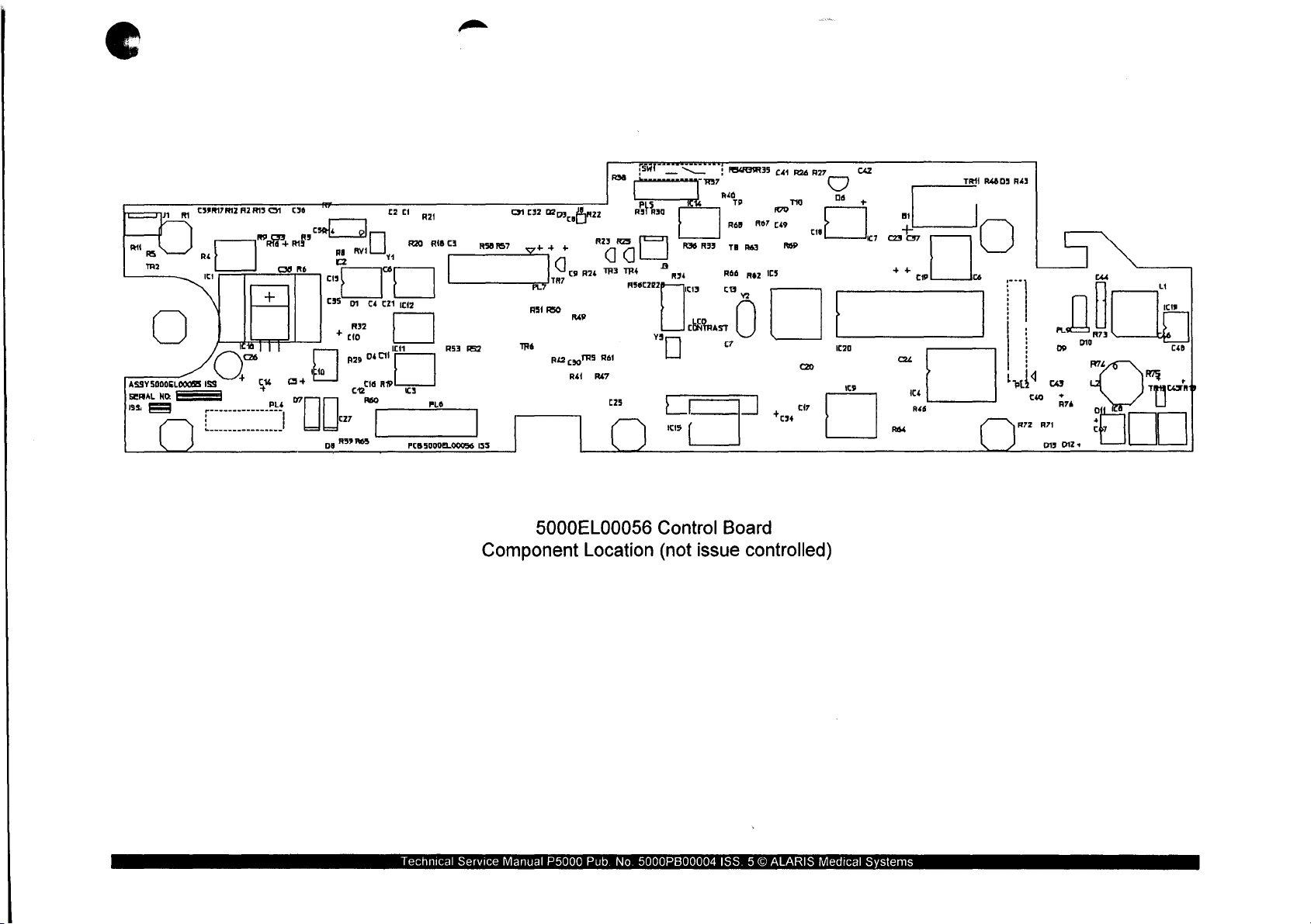
д м $3917
αι
RS
TR?
8375000660065
No
SERAL
ss.
Famed
812
92815
Ré
It
ta
26
153
+
ーーーーーーーーー
}
RS
|]
w
СМ
EAU
+
pus
ини
CIO
cene
at
の
|
p
κι
RH
R36 R33
[cta
[
wer
1
GRIS
Ra
846
4
TE
Réé
ca
c
ctNteast
tr
|
70
2
R63
maz
|
[41
126 R27
тю
R70
1895
105
c 876
tess
7
O
Dá
(+0)
cuz
+
|
Ic?
cao
++
πι
cw
TRI
ce
R4805
„..
!
}
i
!
|,
cu
15
4
R46
R64
Lac
(37
Rá3
!
}
:
|
Ja
uo
us
RA
013
PL
Do
Д
+
012
po?
+
Cas
o
+
中
Rg
matar
и
019
CxB
=
ms | ML
923
Я
ΤΗΣ
Ral
R47
[25
Rat
02
Я
3
TR
RS6EZP2
G
[그
Rag
vs
в
[]
7
人
3
a
cís
css
+
[27
ов
N39
C2
CI
ME
DI
R32
rio
02
ce
R60
R63
RO
Y1
C4
C21
122
ICH
마데
cia
RP
‚сз
PCB
R21
RÍSCI
RS3
pos
FLO
SO00EL.00056
155
O
TRE
132
++
A7
RSI
0293
Bra
+
G
ray > RK
REO
no
Riz
cyoTR5
RA
Technical
Component
Service
Manual
5000EL00056
Location
P5000
Pub.
No.
Control
(not
issue
5000PB00004
Board
controlled)
ISS. 5 ©
ALARIS
Medical
Systems
Page 74
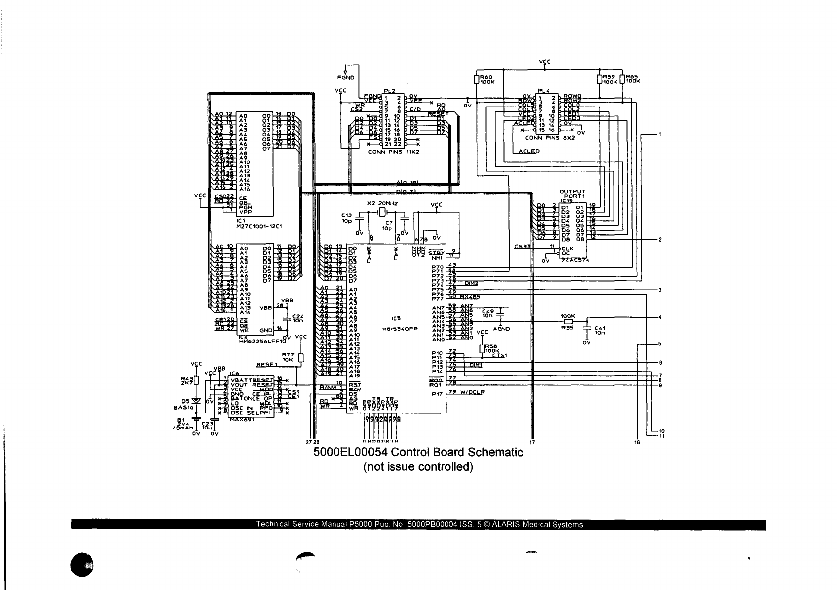
2
+0
う
うう
うう
NAURUN
うう
4
TP
うう
IG
うう
うう
うう
1
SARUN
ví
SARAL
=
M27C1001-12C1
ら
と
と と
ー
ちち
ゆい
と と
ホ
と
m
ちち
いひ
ちと
や
の
ちと
ささ
GS
テア
EROI
ちと
ちょ
ちち
ちち
ちち
ちち
ちち
ちと
ちち
ちょ
と
=
urun
té
2800
URGR
SR
X2
いつ
さゆ
の
ささ
A
1
4
ONU
21
20MHz
IT
H8/5340FP
L
105
ov
We
SODUEA|
5000EL00054
Technical
Service
Manual
P5000
(not
Pub.
Control
issue
controlled)
No.
5000PB00004
Board
Schematic
ISS. 5 ©
ALARIS
Medical
Systems
©
Page 75
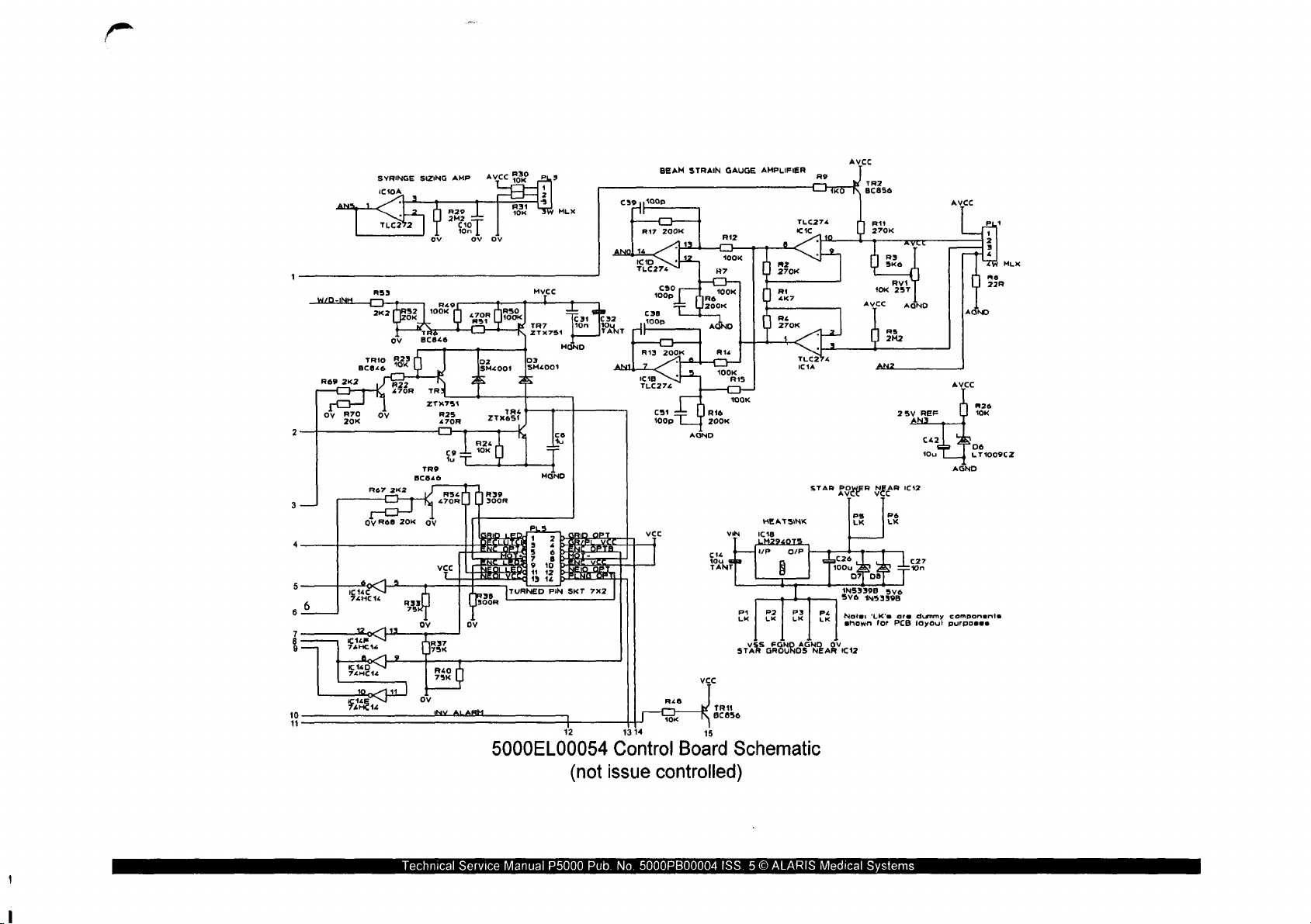
ROP 2K2
4
TRIO
66846
R67
R23
“OK
2K2
Ree
20K
ΖΤΧΤ54
R25
470R
6
8
8
BEAM
STRAIN
GAUGE
AMPLIFIER
ey | 3005
R17
200K
τις
274
κιτς
AVCC
TR7
ZTX751
cst
1009
100K
cie
jou
TANT
R15
VIN
P1
LK
sth
HEATSINK
1018
LHZ940IS
ur
8
P2
LK
FGNO
GROUNOS
AVCC
25v
REF
C42
10u
STAR
POWER
NEAR
ve
4453398
‘LK’s
for
P6
LK
Lear
sve
are
PCB
1612
wn
dummy
¡ayou!
AE
ps
LK
εαν
LK
NEAR
1οου
ov
1N5339B
své
Note:
shown
1C12
OP
РЗ
LK
AGM
R26
10k
Dé
LT1009CZ
AGND
componenia
purposes
кв
TLC274
SKT
7x2
10
11
chnical
5000EL00054
(not
Service
Manuali
P5000
Control
issue
Pu
controlled)
.
5000PB00004
TRY
Bcsse
Board
Schematic
ISS. 5 ©
RIS
Medical
Systems
Page 76
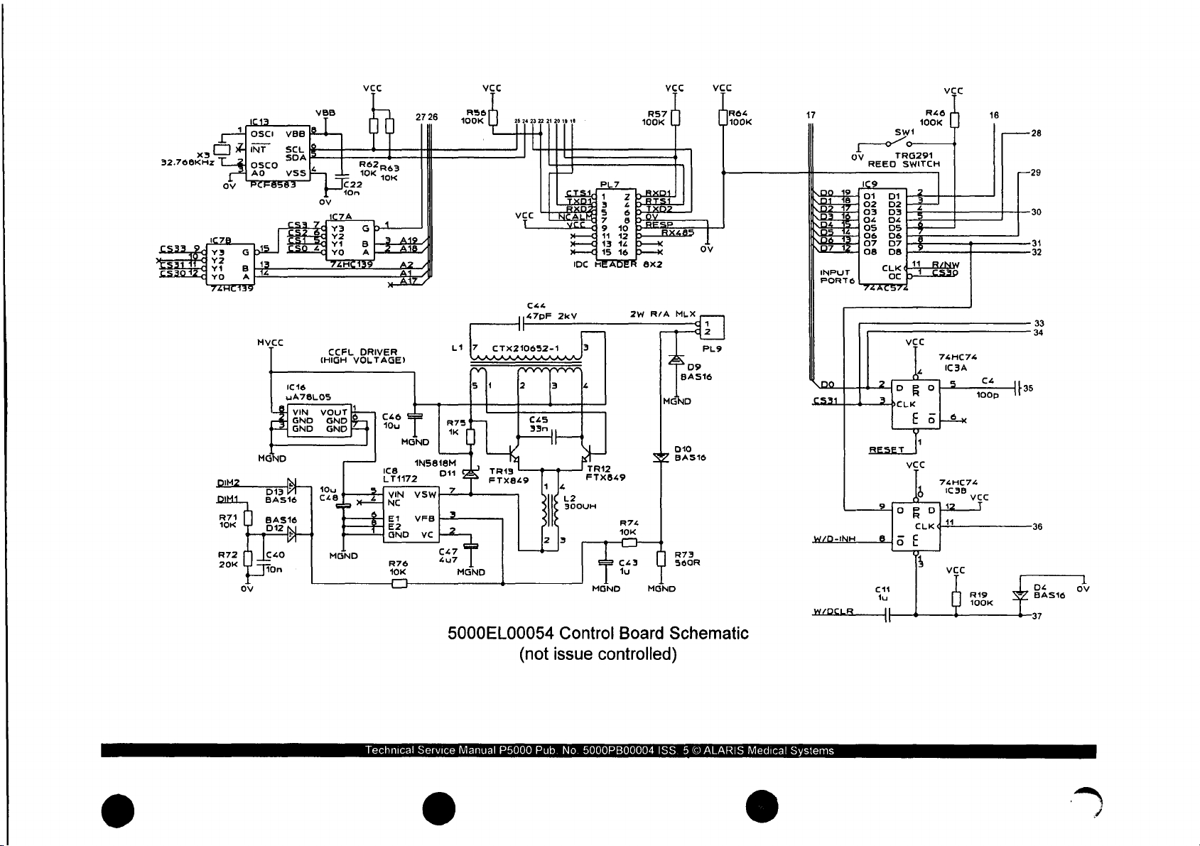
VCC
C46
10u
LT1172
VIN
NC
EL
GND
R76
40K
ru
—
2726
—
1
MGND
1N5816M
vsw ト マズ
VFB
vc
C47
4u7
osc:
veer
хз ov
32.766KHz
MVCC
MG
IM
CCFL
(HIGH
16
IC
nA78L05
GND
GND
pt
DRIVER
VOLTAGE)
D11
ь1
R75
1k
っ
RS6
100K
|7
sh
MGND
VCC
6
24
VCC
T
Cee
147PF
Il
crx210652-1
2
j
TRIS
FTX849
23
22
645
33n
i
21
20
19 18
HH
EE:
NCA
YE 49
2kv
3
||
TT
ale
L2
300UH
2
|s
PLZ
A
1
=
7 8
13
15
IDC
A
(7
3
4
TR12
FTX849
MGND
м
A
n
RS7
100K
2
10
12
16
2W
8x2
R/A
ov
MLX
MGND
BA
p
SZ
Baste
874
10K
c43
lu
R73
56068
MGND
< a a
R64
100K
17
D
19
Do
Bros
23
1
一
тии
89
13189
~
INPUT
PORTS
Do
cs
REED
1Ç9
01
04 04
os 05
os D8 上 之
7ZATS
2
2h
RESET
R46
100K
swt
TRG291
SWITCH
DI
BF
5
}-$——
07
EE
411
cu 4 BW
b
oc
72
vec
‹
oe
E
[ο
E
646x
4
|
vec
b
vec
CS39
74HC74
IC3A
oop
16
——
—29
po
28
,
20
31
32
x
34
Technical
5000EL00054
Service
Manual
P5000
(not
Pub.
Control
issue
controlled)
No.
5000PB00004
Board
Schematic
ISS. 5 ©
ALARIS
Medical
Systems
Page 77

vec
28
29
30
31
32
33
34
WINDOW
36
ca
22p
|
T
ον
13
100K
1
119
74H
cs
74HC14
OH
IC14A
74H01
618
DA
BAS16
1
ον
ον
WATCHDOG
4
2
Hp
R34
75K
102
74HC4060
—
è
I
ov
04
2 上 ex
R36
75K
-Z
ES:
<
13
12
101
x
x
Reo
τοις
13
J
BC846
TRE
14
ov
vec
45
o
v
|
ov
УСС
R47
100K
cao
10n
=IC2
KSOİ
Ч1
2
K
x
ALARMI
PCALERİŞ
<IC1
<IC1
=
ció
10
u
TANT
<C3
<CS
L
LL
τπτ
615 616 Ci7 cig C19
fon
τ
100
3
5 é
3
=
I
css
10
On
10m
р
4
[70656
46 D УСС
ans
p
BATY
p—
R
AVEC
1
AGND
<IC7
LOL
τι
fon
8X2
«IC8
τ
fon
"
X
<IC2
о
C35
16
TANTO
<IC9
LL
τ τ
10m
моно
C20
ov
<ICS
Cd
16
TANTO
<IC11
c21
1on
<IC6
=
C37
TANTO
<C12
IL
τ |
C6
don
~«IC10
十
cs
<IC15
1
C25
10n
M
VCC
ANZ
vec
TANT
νςς
ov
ov
VIN
|
1
1
37
Technical
5000EL00054
Service
Manual
P5000
(not
Pub.
Control
issue
controlled)
No.
5000PB00004
Board
ISS. 5 ©
Schematic
ALARIS
Medical
Systems
Page 78
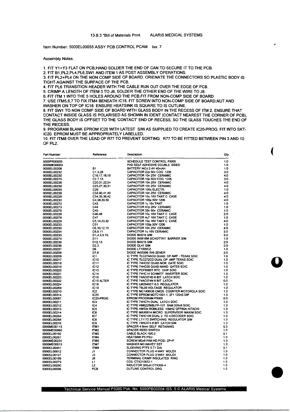
item
Number:
5000EL00055
13.8.3
ASSY
*Bill of
PCB
Materials
CONTROL
Print
PCAM
ALARIS
Iss:
7
MEDICAL
SYSTEMS
Assembiy
1.
FIT
Y1+Y3
2.
FIT
B1,PL2,PL4,PL6,SW1
3.
FIT
PL2+PL4
TIGHT
AGAINST
4.
FIT
PL6
5.
CRIMP A LENGTH
6.
FIT
ITM 1 INTO
7.
USE
ITM5,6,7
WASHER
8.
FIT
SW1
CONTACT
THE
GLASS
THE
RECESS.
9.
PROGRAM
IC20.
EPROM
10.
FIT
ITM8
OF
PL2.
Part
Number
5000PR00005
0000ME
00053
0000EL00208
0000EL00232
0000EL00230
0000EL00270
0000EL00230
0000EL00230
0000EL00030
0000EL00230
0000EL00229
0000EL00233
0000EL00272
0000EL00273
.
00006 ㄴ 00276
0000EL00229
0000EL00278
0000EL00229
0000EL00233
0000EL00230
0000EL00234
0000EL00235
0000EL00274
0000EL
00235
0000EL00236
0000EL00237
0000EL00206
0000EL00209
0000EL00217
0000EL00218
0000EL00219
0000EL00220
0000EL00221
0000EL00223
0000EL00222
0000EL00224
0000EL00269
0000EL00210
0000EL00314
5000EL00057
0000EL00211
0000EL00212
0000EL00313
0000EL00214
0000E
L00264
0000EL00268
0000EL00216
0000ME00115
5000ME
00065
0000EL00182
0000EL00261
0000ME00231
0000ME00015
0000EL00451
0000EL00012
0000EL00131
0000EL00189
0000EL00279
0000EL00280
5000EL00056
Notes:
FLAT
ON
THE
TRANSITION
THE 5 HOLES
TO
ON
TOP
TO
NON
INSIDE
BODY
BLANK
MUST
OVER
ON
PCB,HAND
THE
NON
SURFACE
HEADER
OF
ITEM 3 TO
FIX
ITM4
OF
1C18.
COMP
GLASS
IS
OFFSET
EPROM
BE
APPROPRIATELY
THE
LEAD
AND
ITEM 1 AS
COMP
OF
WITH
AROUND
BENEATH
ENSURE
SIDE
OF
IS
POLARISED
TO
IC20
OF
Reference
BI
C1,3,28
C16,17,18,19
C2.7.13
C20,21,22,24
C25,27,30,31
C26
C33,40,41,49
C34,35,36,42
C4,38,39,50
C43
C44
C45
64648
C47
C5,14,23,32
651
C6,10,12,15
C3,9,11
D1,4,5,9,10,
D11
D12,13
D2,3
D6
D7.8
IC1
IC10
1011
IC12
IC13
1614
1615
1C15
ALTER
IC18
IC19
IC2
1620
IC20-PROG
КЗ
IC4
105
166
IC7
ice
IC9
TM
ITM2
ITM3
ITM4
iTM5
ITM7
ΙΤΜΒ
91
J3
J8
L1
12
PCB
SOLDER
SIDE
THE
J8,
HEATSINK
BOARD
THE
WITH
R77
TO
THE
POST
OF
BOARD.
PCB.
THE
CABLE
SOLDER
THE
IC18.
FIT
WITH
AS
SHOWN
'CONTACT
LATEST
LABELLED.
PREVENT
Description
SCHEDULE
PAD
BATTERY
CAPACITOR
CAPACITOR
CAPACITOR
CAPACITOR
CAPACITOR
CAPACITOR
CAPACITOR
CAPACITOR
CAPACITOR
CAPACITOR
CAPACITOR
CAPACITOR
CAPACITOR
CAPACITOR
CAPACITOR
CAPACITOR
CAPACITOR
CAPACITOR
DIODE
DIODE
DIODE
DIODE
DIODE
DIODE
IC
TYPE
IC
TYPE
IC
TYPE
IC
TYPE
IC
TYPE
IC
TYPE
IC
TYPE
IC
TYPE
IC
TYPE
IC
TYPE
IC
TYPE
IC
TYPE
EPROM
IC
TYPE
IC
TYPE
IC
TYPE
IC
TYPE
IC
TYPE
IC
TYPE
IC
TYPE
SPACER
SPACER
CABLE
HEATSINK
SCREW
WASHER
SLEEVING
CONNECTOR
CONNECTOR
TERMINAL
COIL
INDUCTOR
OUTLINE
END
ASSEMBLY
RUN
THE
PCB,FIT
SCREW
IS
SQUARE
GLASS
END
S/W
SORTING.
SELF
ADHESIVE
NiCd
BAS16
IN5818M
BAS16
GL41
LT1009CZ
1N53398
TLC274ACD
TLC272CD
74HC02
74HC00
PCF8583T
74HC14
74AC574D 8 BIT
74ACS74N 8 BIT
LM2940CT-5.0
78L05
MC14060B
EPROM
PROGRAM
74HC74
HM62256BLFP-10T
H8/S34
MAX691A
74HC139
LT1172
74HC574 8 BIT
4.8mm
REED
BLACK
P5
M3x8
M3
PTFE
CRIMP
CTX210652-1
CONTROL
OF
CAN
TO
OPERATIONS.
ORIENATE
OUT
OTHER
OVER
END
FROM
INTO
TO
BODY
IN
IDENT
OF
RECESS,
AS
SUPPLIED
TEST
CONTROL
DOUBLE
2.4V
40mAH
22p
50v
COG
10n
25V
CERAMIC
10p
50V
COG
10n
25V
CERAMIC
10n
25V
CERAMIC
100u
ELECTR.
10n
25V
CERAMIC
10u
16V
TANT C CASE
100p
SOV
1206
1u
16v
TANT
47p
2KV
CERAMIC
33n 50v
CERAMIC
10u
16V
TANT C CASE
4u7
16V
TANT C CASE
10u
16V
TANT C CASE
100p
SOV
1206
10n
25V
CERAMIC
1u
16V
CERAMIC
SM
SCHOTTKY
SM
SM
5V6
ZENER
QUAD
DUAL
QUAD
NOR
QUAD
NAND
RTC
SCHMITT
VOLTAGE
CMOS
M27C1001-1
P5000
DUAL
LATCH
ROMLESS
MICRO
DUAL 2 TO 4 DECODER
SWITCHING
SELF
RETAINING
SWITCH
16/0.2
PSU
PAN
HD POS:
WAVEY
SST
0.71
DIA
PLUG 4 WAY
PLUG 3 WAY
INSULATED
300uH
CTX300-4
DRG
SECURE
THE
THE
OF
THE
NON-COMP
NON-COMP
IS
OUTLINE.
IN
THE
(CONTACT
SO
TO
R77
TO
P5000
SIDED
1206
1206
BARRIER
OP
AMP - TEXAS
OP
AMP
GATE
GATES
CHIP
SOIC
INVERTER
LATCH
SOIC
LATCH
REGULATOR
REGULATOR
COUNTER
2F1
SOIC
RAM
32Kx8
10MHZ
SUPERVISOR
REGULATOR
LATCH
SM
ZP+P
MOLEX
MOLEX
RING
IT
TO
CONNECTORS
EDGE
WIRE
SIDE
SIDE
RECESS
NEAREST
THE
GLASS
CREATE
BE
FITTED
SM
SOIC
SOIC
SOIC
MOTOROLA
DIP
SOIC
MAXIM
SOIC
SOIC
HITACHI
SOIC
S/M
TEXAS
120nS
OFP80A
THE
PCB.
SO
OF
PCB.
TO
J8.
OF
BOARD
OF
BOARD,NUT
OF
ITM
THE
TOUCHES
1C20-PROG,
BETWEEN
SOIC
SOIC
PLASTIC
2.
ENSURE
CORNER
FIT
PIN 3 AND
AND
THE
INTO
Qty
1.0
10
1.0
3.0
4.0
30
40
40
10
40
40
40
10
10
10
20
10
40
1.0
40
3.0
5.0
10
20
20
10
2.0
1.0
1.0
1.0
1.0
1.0
10
1.0
0.0
1.0
10
1.0
1.0
00
1.0
BODY
THAT
OF
END
IS
PCB),
OF
SKT-
10
Technical
Service
Manual
P5000
Pub.
No.
5000PB00004
ISS. 5 ©
ALARIS
Medical
Systems
Page 79

Item
Number:
Part
Number
0000EL00262
0000EL00228
0000EL00104
1000EL00135
0000EL00011
0000EL00147
0000EL00239
0000EL00244
0000EL00240
0000EL00231
0000EL00271
0000EL00247
0000EL00248
0000EL00241
0000EL00248
0000EL00249
0000EL00244
0000EL00250
0000EL00249
0000EL00251
0000EL00252
0000EL00242
0000EL00244
0000EL00244
0000EL00243
0000EL00248
0000EL00244
0000EL00271
0000EL00248
0000EL00042
0000EL00245
0000EL00246
0000EL00044
0000Е100450
1000EL00141
0000EL00277
0000EL00225
0000EL00021
0000EL00067
0000EL00226
0000EL00128
0000EL00315
5000EL00055
13.8.3
"Bill
ASSY
Reference
PL2
PL4
PLS
PL6
PL?
PLO
RI
R18,19,27,32
R2,4,11
R20
R21
R22,25,51,54
R23,24,26,30
R3
R31,41,48,62
R33,34,36,37
R35,46,47,49
R38,39
R40
R42,53,67,69
R43
RS,29
R50,56,57,58
RS9,60,64,65
R6,13,16,17
R63,66,71,74
R7.12.14.15
R73
R76
R77
R8
R9,75
RVI
SKT-1C20
SW1
TR12,13
TR2,11
TR3,7
TR4
TR5,6.8,9,10
Y1.3
Y2
of
PCB
Materials
CONTROL
Description
CONNECTOR
CONNECTOR
CONNECTOR
ASSY
CONNECTOR
CONNECTOR
RESISTOR
RESISTOR
RESISTOR
RESISTOR
RESISTOR
RESISTOR
RESISTOR
RESISTOR
RESISTOR
RESISTOR
RESISTOR
RESISTOR
RESISTOR
RESISTOR
RESISTOR
RESISTOR
RESISTOR
RESISTOR
RESISTOR
RESISTOR
RESISTOR
RESISTOR
RESISTOR
RESISTOR
RESISTOR
RESISTOR
POTENTIOMETER
iC
SWITCH
TRANSISTOR
TRANSISTOR
TRANSISTOR
TRANSISTOR
TRANSISTOR
CRYSTAL
CRYSTAL
Print
PCAM
CABLE
SOCKET
PLUG
PLUG
SOCKET
16
PLUG
PLUG 2 WAY
4K7
100K
270K
10M
560K
470R
10K
5K6
10K
75K
100K
300R
75K
2K2
2K7
2M2
100K
100K
200K
10K
100K
560K
10K
10K
22R
1KO
32W-DIL
REED
FR
ZTX849
BC856
FZT
ZTX651
BC846
32.768KHZ
20.0MHZ
ALARIS
Iss:
22
16
WAY
16
0.25W
0.25W
0.25W
0.125W
0.25W
0.25W
0.25
0.25W
0.25
0.25W
0.25W
0.25W
0.25W
0.25W
0.25W
0.125W
0.25W
0.25W
0.25W
0.25
0.25W
0.25W
0.25
0.25W
0.25W
0.25W
10K
TURNED
TRG291
PNP
751
NPN
WATCH
HC49/4U
MEDICAL
7
WAY (SAMTEC
WAY
(SAMTEC
14
WAY
RIBBON
WAY
HEADER
RVA
2%
2%
2%
2%
2%
2%
2%
2%
2%
2%
2%
1%
2%
25
TURNS
PIN
P5
NPN
ZETEX
SM
SOT22
3
SOT223
S/M
MOLEX
SYSTEMS
BDL-111-T-E)
SDL-107-TT-11)
Qty
10
1.0
1.0
1.0
1.0
10
10
4.0
3.0
1.0
10
40
4.0
1.0
4.0
4.0
4.0
2.0
1.0
4.0
1.0
2.0
4.0
40
40
4.0
40
1.0
1.0
1.0
1.0
2.0
1.0
1.0
1.0
2.0
2.0
2.0
10
5.0
2.0
1.0
Technical
Service
Manual
P5000
Pub.
No.
5000PB00004
ISS. 5 ©
ALARIS
Medical
Systems
Page 80

5.4
Control
Board
(mark
3):
5000EL00064
5000EL00065
For
Schematic
See
next
sheets.
Component
Control
Diagram
BOM
See
5000EL00054
Location
Section
(not
(not
5.4
issue
issue
(Mark
controlled)
controlled)
2).
Technical
Service
Manual
P5000
Pub.
No.
5000PB00004
ISS. 5 ©
ALARIS
Medical
Systems
Page 81
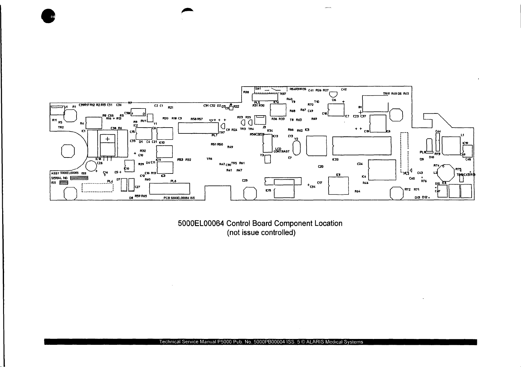
AssY
5000ELO0065
E
5
E
C3OAI7RZ
O“
tss
[
77
ἐξ
οσα
REAB
ce
「
R9
+
ανοσία
Rió
CS1
638
C33
яз
+
RO
cem
„E
e
7
i
7
cs
635
pg
ROZ
+
C27
R59
AVI
D1
cio
020
cnt
R65
C4
C21
VAM
POLS
ZA
R20
dg
c
кр
Pr
ra
ROO
|
RS3 R52
Pe
PCB
5000EL00084
RS6RS7
ISS
CH
Gz
ct
FL7
251
TRe
0203,
+
d
dés
RASO
R42
2
9-22
"
RZ
d
CaoTR5
Re1
Ré1
R47
nan
R25
25
‘=
d
TE
1501
PSSST
|
Sí
R31
R30
TX
5
Ets
T
}
25439935
RS?
RO
È
|
R36
R33
Ta
R66
it
[
|
41
926
927
C42
(
)
5
Ro
©
R63
R62
=>
R69
©
20
co
rs
εσ
|
+e
It?
|
BI
¢23
G7
++
cu
ce
Re
Réé
ret
ce
pisos
(
aia
june
:
|
i
då
, '
Pa
pi
id
| |
i |
EN
872
)
|
i
care
ca
R74
va
PL
09
+
02:
R73
>“
て
44
Ros
o
9
c
и
κ
E
cs
RT
mare
Technical
5000EL00064
Service
Manual
Control
(not
P5000
issue
Pub.
Board
controlled)
No.
5000PB00004
Component
ISS. 5 ©
ALARIS
Location
Medical
Systems
Page 82
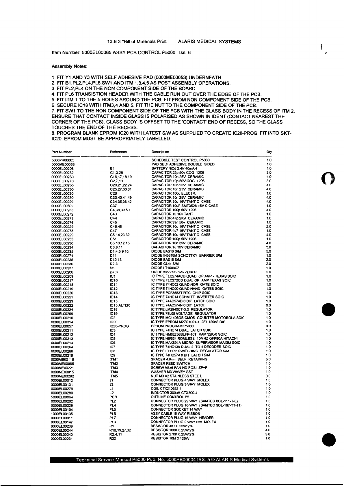
item
Number:
5000EL00065
13.8.3
ASSY
“Bill
PCB
of
Materials
CONTROL
Print
P5000
ALARIS
Iss:
6
MEDICAL
SYSTEMS
Assembly
.
FIT
Y1
->
.
FIT
B1,PL2,PL4,PL6,SW1
.
FIT
PL2,PL4
PWD
.
FIT
PL6
.
FIT
ITM 1 TO
.
SECURE
NOOO
.
FIT
SW1
ENSURE
CORNER
TOUCHES
8.
PROGRAM
IC20.
EPROM
Part
Number
5000PR00005
0000ME00053
0000EL00208
0000EL00232
0000EL00230
0000EL00270
0000EL00230
0000EL0C230
0000E
L00030
0000EL00230
0000EL00229
0000Е1.00502
0000EL00233
0000EL00272
0000EL
00273
0000EL00276
0000EL00229
0000EL00278
0000EL00229
0000EL00233
0000EL00230
0000EL
00234
0000EL00235
0000EL00274
0000EL00235
0000EL00236
0000EL00237
0000€L
00206
0000EL00209
0000EL00217
0000EL00218
0000EL00219
0000EL00220
0000EL00221
0000EL00223
0000EL00222
0000EL00224
0000EL00269
0000EL00210
0000EL00314
5000EL00057
0000EL00211
0000EL00212
0000EL00313
0000EL00214
0000EL00264
0000EL00268
0000EL00216
0000ME00115
S000ME
00065
0000ME00221
0000ME00015
0000ME00292
0000EL00012
0000EL00131
0000EL00279
0000Е1.00280
5000EL00064
0000EL00262
0000EL00228
0000EL00104
1000EL00135
0000EL00011
0000EL00147
0000EL00239
0000EL00244
0000EL00240
0000EL00231
Notes:
AND
Y3
WITH
ON
THE
TRANSISTION
THE 5 HOLES
IC18
WITH
TO
THE
THAT
CONTACT
OF
THE
PCB),
THE
END
BLANK
MUST
SELF
AND
NON
HEADER
ITM3,4
NON
COMPONENT
INSIDE
GLASS
OF
THE
EPROM
BE
APPROPRIATELY
Reference
B1
C1,3,28
C16,17,18,19
C2.7,13
C20,21,22,24
C25,27,30,31
C26
C33,40,41,49
C34,35,36,42
C37
C4,38,39,50
C43
C44
C45
C46,48
C47
С5.14,23,32
C51
C6,10,12,15
C8,9,11
D1,4,5,9,10,
D11
D12,13
D2,3
D6
D7,8
IC1
IC40
IC11
IC12
IC13
IC14
IC15
1615
1C18
IC19
IC2
1020
1C20-PROG
1C3
IC4
Ics
IC6
IC7
108
109
ITM1
ITM2
ITM3
ITM4
ITM5
J1
3
L1
12
PCB
PL2
PL4
PLS
PL6
PL7
PLO
RI
R18,19,27,32
R2,4,11
R20
ADHESIVE
ITM
1,3,4,5
COMPONENT
WITH
AROUND
AND
5.
GLASS
BODY
RECESS.
!C20
WITH
ALTER
THE
THE
FIT
SIDE
IS
PAD
(0000ME00053)
AS
POST
SIDE
CABLE
PCB,
THE
NUT
OF
THE
IS
POLARISED
OFFSET
LATEST
LABELLED.
Description
SCHEDULE
PAD
SELF
BATTERY
CAPACITOR
CAPACITOR
CAPACITOR
CAPACITOR
CAPACITOR
CAPACITOR
CAPACITOR
CAPACITOR
CAPACITOR
CAPACITOR
CAPACITOR
CAPACITOR
CAPACITOR
CAPACITOR
CAPACITOR
CAPACITOR
CAPACITOR
CAPACITOR
CAPACITOR
DIODE
DIODE
DIODE
DIODE
DIODE
DIODE
IC
TYPE
IC
TYPE
IC
TYPE
IC
TYPE
IC
TYPE
iC
TYPE
IC
TYPE
IC
TYPE
IC
TYPE
IC
TYPE
IC
TYPE
IC
TYPE
EPROM
IC
TYPE
IC
TYPE
IC
TYPE
IC
TYPE
IC
TYPE
IC
TYPE
IC
TYPE
SPACER
SPACER
SCREW
WASHER
NUT
M3
CONNECTOR
CONNECTOR
COIL
CTX210652-1
INDUCTOR
OUTLINE
CONNECTOR
CONNECTOR
CONNECTOR
ASSY
CONNECTOR
CONNECTOR
RESISTOR
RESISTOR
RESISTOR
RESISTOR
ASSEMBLY
OF
THE
BOARD.
RUN
FIT
FROM
TO
THE
PCB
AS
TO
THE
S/W
AS
TEST
ADHESIVE
NiCd
2.4V
22p
10n
10p
10n
25V
10n
25V
100u
10n
25V
10u
10uF
100p
1u
16v
47p
2KV
33n
50v
10u
4u7
10u
100p
10n
25V
1u
16V
BAS16
S™
IN5818M
SCHOTTKY
BAS16
SM
GL41
S/M
LT1009CZ
1N5339B
5V6
TLC274ACD
TLC272CD
74HC02
74HC00
PCF8583T
74HC14
SCHMITT
74AC574D 8 BIT
74AC574N 8 BIT
LM2940CT-5.0
78L05
VOLTAGE
MC14060B
EPROM
M27C1001-1
PROGRAM
74HC74
DUAL
HM62256BLFP-10T
H8/534
ROMLESS
MAX691A
74HC139
LT1172
SWITCHING
74HC574 8 BIT
4.8mm
SELF
REED
SWITCH
M3x6
PAN
M3
WAVEY
A2
STAINLESS
PLUG 4 WAY MOLEX
PLUG 3 WAY
300uH
CONTROL
PLUG
PLUG
SOCKET
CABLE
16
WAY
PLUG
PLUG 2 WAY
4K7
0.25W
100K
0.25W
270K
0.25W
10M
0.125W
UNDERNEATH.
OPERATIONS.
OUT
OVER
NON
THE
COMPONENT
COMPONENT
WITH
THE
P5000
1206
1206
16V C CASE
1206
1206
BARRIER
OP
OP
NOR
GATE
NAND
CHIP
INVERTER
LATCH
LATCH
REGULATOR
REGULATOR
COUNTER
LATCH
RAM
10MHZ
SUPERVISOR
REGULATOR
LATCH
RETAINING
POSI
ZP+P
STEE
L
MOLEX
WAY
(SAMTEC
WAY
(SAMTEC
14
WAY
WAY
HEADER
R/A
2%
2%
GLASS
IN
END
TO
SIDED
AMP - TEXAS
AMP
TEXAS
SOIC
GATES
SOIC
SOIC
2F1
120nS
SOIC
32Kx8
QFP80A
SM
MOLEX
SHOWN
'CONTACT
SUPPLIED
CONTROL
DOUBLE
40mAH
50v
COG
25V
CERAMIC
50V
COG
CERAMIC
CERAMIC
ELECTR.
CERAMIC
16V
TANT C CASE
SMT3528
50V
TANT
CERAMIC
CERAMIC
16V
TANT C CASE
16V
TANT C CASE
16V
TANT C CASE
50V
CERAMIC
CERAMIC
ZENER
QUAD
DUAL
QUAD
QUAD
RTC
CMOS
P5000
MICRO
DUAL 2 TO 4 DECODER
HD
SST
CTX300-4
PS
22
16
RIBBON
16
2%
EDGE
SIDE
OF
BODY
IDENT
(CONTACT
OF
RECESS,
CREATE
S/M
SOIC
SOIC
SOIC
SOIC
MOTOROLA
DIP
SOIC
HITACHI
MAXIM
SOIC
SM
BDL-111-T-E)
SDL-107-TT-11)
OF
THE
SIDE
OF
THE
PCB.
IN
THE
SO
IC20-PROG,
SOIC
SOIC
PCB.
THE
PCB.
RECESS
NEAREST
THE
FIT
GLASS
INTO
Qty
1.0
1.0
1.0
3.0
4.0
3.0
40
4.0
4.0
4.0
40
1.0
40
10
1.0
1.0
2.0
10
40
1.0
4.0
30
5.0
1.0
2.0
20
10
2.0
1.0
10
10
10
1.0
1.0
1.0
0.0
10
1.0
10
10
0.0
10
1.0
1.0
10
1.0
10
1.0
5.0
10
10
1.0
0.0
1.0
10
1.0
1.0
10
10
1.0
1.0
1.0
1.0
1.0
10
4.0
3.0
10
OF
THE
ITM
SKT-
2.
Technical
Service
Manual
P5000
Pub.
No.
5000PB00004
ISS. 5 ©
ALARIS
Medical
Systems
Page 83
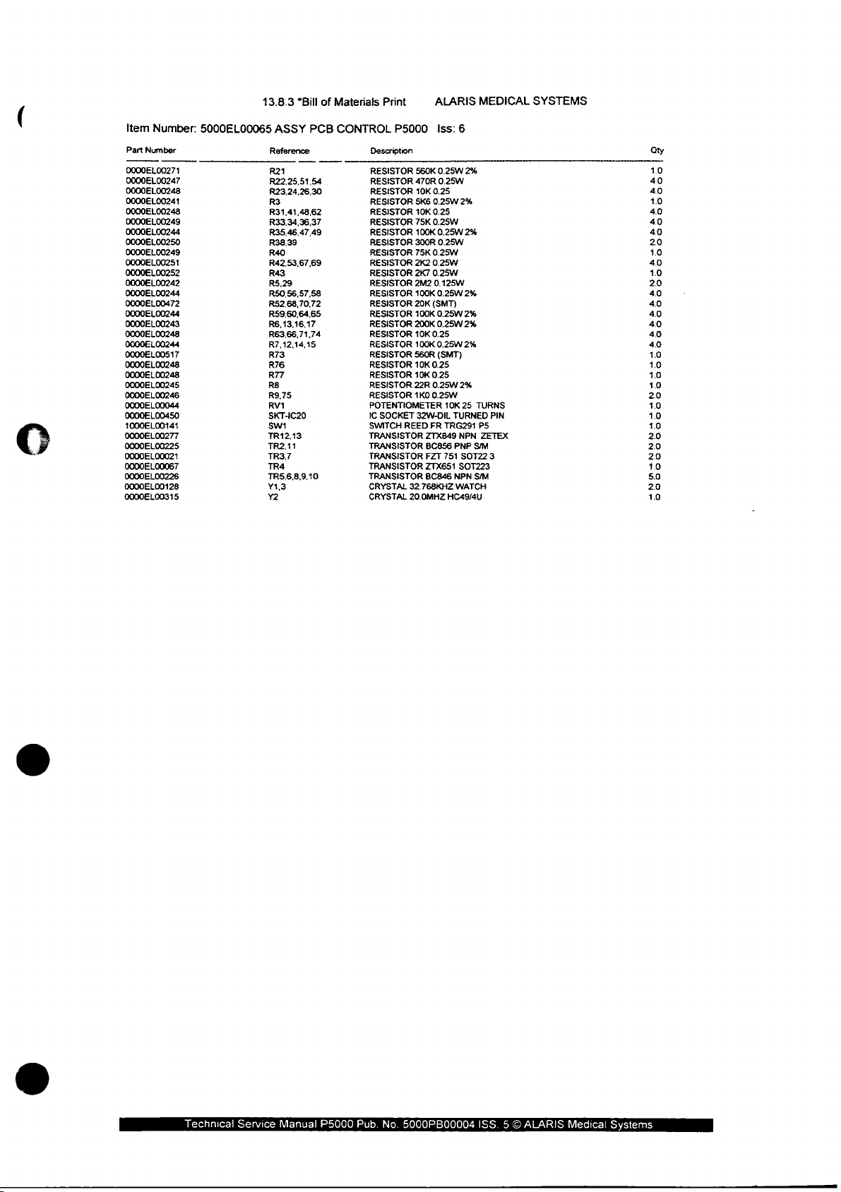
Item
Number:
Part
Number
0000EL00271
0000EL00247
0000EL00248
0000EL00241
0000EL00248
0000EL00249
0000EL00244
0000EL00250
0000EL00249
0000EL00251
0000EL00252
0000EL00242
Ο0ΟΟΕΙ
00244
0000EL00472
0000EL00244
0000EL00243
0000EL00248
0000EL00244
0000EL00517
0000EL00248
0000EL00248
0000EL
00245
0000EL00246
0000EL00044
0000EL00450
1000EL00141
0000EL00277
0000EL00225
0000EL00021
0000EL00067
0000EL00226
0000EL00128
0000EL00315 Y2
5000EL00065
13.8.3
*Bill
ASSY
Reference
R21
R22,25,51,54
R23,24,26,30
R3
R31,41,48,62
R33,34,36,37
R35,46,47,49
R38,39
R40
R42,53.67,69
R43
R5,29
R50,56,57,58
R52,68,70,72
R59,60,64,65
R6,13,16,17
R63,66,71,74
R7,12,14,15
R73
R76
R77
R8
R9,75
RV1
SKT-IC20
Swi
TR12,13
TR2,11
TR3,7
TR4
TR5.6,8,9,10
Y1,3
of
PCB
Materials
CONTROL
Description
RESISTOR
RESISTOR
RESISTOR
RESISTOR
RESISTOR
RESISTOR
RESISTOR
RESISTOR
RESISTOR
RESISTOR
RESISTOR
RESISTOR
RESISTOR
RESISTOR
RESISTOR
RESISTOR
RESISTOR
RESISTOR
RESISTOR
RESISTOR
RESISTOR
RESISTOR
RESISTOR
POTENTIOMETER
1C
SWITCH
TRANSISTOR
TRANSISTOR
TRANSISTOR
TRANSISTOR
TRANSISTOR
CRYSTAL
CRYSTAL
Print
P5000
SOCKET
560K
470R
10K
5K6
10K
75K
100K
300R
75K
2K2
2K7
2M2
100K
20K
100K
200K
10K
100K
560R
10K
10K
22R
1K0
32W-DIL
REED
FR
ZTX849
BC856
FZT
ZTX651
BC846
32.768KHZ
20.0MHZ
ALARIS
Iss:
0.25W
0.25W
0.25
0.25W
0.25
0.25W
0.25W
0.25W
0.25W
0.25W
0.25W
0.125W
0.25W
(SMT)
0.25W
0.25W
0.25
0.25W
(SMT)
0.25
0.25
0.25W
0.25W
10K
TURNED
TRG291
PNP
751
NPN
WATCH
HC49/4U
6
2%
2%
2%
2%
2%
2%
2%
2%
25
TURNS
NPN
SIM
SOT22
SOT223
S/M
MEDICAL
PIN
P5
ZETEX
3
SYSTEMS
αυ
1.0
40
40
1.0
4.0
4.0
40
20
10
4.0
1.0
20
4.0
40
40
4.0
40
4.0
1.0
10
1.0
10
20
10
1.0
1.0
20
2.0
2.0
1.0
5.0
20
1.0
Technical
Service
Manual
P5000
Pub.
No.
5000PB00004
ISS. 5 ©
ALARIS
Medica!
Systems
Page 84

5.5
Display
Board:
5000EL00036
Display
has
See
no
next
Board
Bill
of
sheet.
Display
5000EL00036
Materials
or
Board
can
only
Component
Schematic
be
purchased
Layout.
(not
issue
as a module
controlled)
therefore
it
Technical
Service
Manuai
P5000
Pub.
No.
5000PB00004
ISS. 5 ©
ALARIS
Medical
Systems
Page 85

рана
FE
GND
vec
]
CONNECTED
PAD
TO
BEZEL
ND
R1
10K
<<
81
1001
1062
LL
|
Li
]
|
It
DO
T7500
n
<
A
vec
JD)
<
2
>
|
TZ
||
op
000MHz
4
C1
Up
ov
“E
nm
z
2?
=
L
eqs
f
1
9
11
47
2
6
10
12
14
18
RST
1
R
4x2
o
гу
7
VEC
|
iz
CI
A
=
Gist
=
그
ov
그
=
8
I
ひひ
T1
72
AB13
AB14
^в15
о
RIV
ono
ceo
"eo
HSCP
COATA
chi
て
DSPON
ερ
00009
LP
ロタ
MOS
mee
MD2
MD3
ESO
co
DUAL
SOSEL
oo
nw
$4
T6963C
LER
一 一 一
L3
a
D
τ]
ㅁㅁㅁ
ㅁ
700
i
47uH
01
PNP 106
|
DS
AM
4148
AI
DEST
Az
r
vec
Re
GNDPZ
SL
7
nu
UN
oo
nn
ㄷㄷ
oslí
07
08
09
010
9
N
o
“DD
aca
N
95
+00
8899
N
00
NN
vò
x
o
u
045
046
047
048
049
989
052
000
QUA
wud
061
063
065
066
068
МИ
ン
id
dd
dd
ン
ン
ン
ン
ン
ン
ン
ン
ン
ン
ノン
ン
ノン
プ
ノノ
アプ
|
ン
Technical
5000EL00036
(not
Service
Manual
P5000
Display
issue
Pub.
controlled)
No.
5000PB00004
Board
Schematic
ISS. 5 ©
ALARIS
Medical
Systems
Page 86

5000EL00036
(not
Display
issue
controlled)
Board
3
Schematic
Technical
Service
Manual
P5000
Pub.
No.
5000PB00004
ISS. 5 ©
ALARIS
Medical
Systems
Page 87

{71
LZ,
トー
a
ーー
2
N
N
N
xloo1
2401
3 4
<
レー
~
5000EL00036
(not
LIQUID
CRYSTAL
240 x 64
TRANSMISSIVE
Display
issue
controlled)
DISPLAY
PIXEL
Board
N
MODE
Schematic
Technical
Service
Manual
P5000
Pub.
No.
5000PB00004
ISS. 5 ©
ALARIS
Medical
Systems
Page 88

Усс
STOP
LED-YEL
START
LED-GRN
BATTERY
LED-YEL
51
——
O
P-SW
1NL148
S2
Ml
‚р
—
о
P-SW
1N4148
sz
<
P-SW
2148
bé
У,
D8
SL
O
—о
P-SW
Pa
P-SW
1N4
O
1N4İZ8
ss
SW
14
N
Se.
一
一
P-SW
D11
4
N4148
D9
8
s7
ο
P-SW
D12
1N4148
$8
ue
<
D13
P-SW
1N4148
5
|
2
ро
P-SW
1N4
ο
D14
148
SO1
ο
ο
P-SW
D15
1N4148
VEC
10u
ov
de
OV
AC
LED-YEL
D4
10n
—
?
ov
Rond
COLIS
VEC
LLEDzd
ACLEDİ
※ーー
Ov
J4
HEADER
!
5
g3
11
13
15
R11
300R
8X2
2
PRows
6
bCoLo
10
Pres
12
pLED3
14
bov
16
p—
R10
一
]
M
M
300R
M
M
300R
R12
y
V
Xx
OV
Technical
5000EL00036
Service
Manua!
|
(not
P5000
Display
issue
Pub.
No.
Board
controlled)
5000PB00004
Ť
ον
Schematic
ISS. 5 ©
ALARIS
Medical
costr
Systems
Page 89

5.6
RS232/485
Board:
5000EL00017
5000EL00003
5000EL00022
5000EL00028
See
next
sheets.
Component
RS232/485
BOM
BOM
RS232
RS232/485
Layout
Board
Board
Board
Schematic
(not
(not
(not
(not
issue
issue
issue
issue
controlled)
controlled)
controlled)
controlled)
Technical
Service
Manual
P5000
Pub.
No.
5000PB00004
ISS. 5 ©
ALARIS
Medical
Systems
Page 90

PLI
|
ага
O
=
CA
ors
3
2
PP6
o
105
op7
Li
mn
D8 D?
ni
ps
RORIO
DPI
| |
OP4
ϱ7
к
ОРЗ
OP2
1
Sii
)
5000EL00017
Component
Location
RS232/RS485
(not
issue
Board
controlled)
Technical
Service
Manual
P5000
Pub.
No.
5000PB00004
ISS. 5 ©
ALARIS
Medical
Systems
Page 91
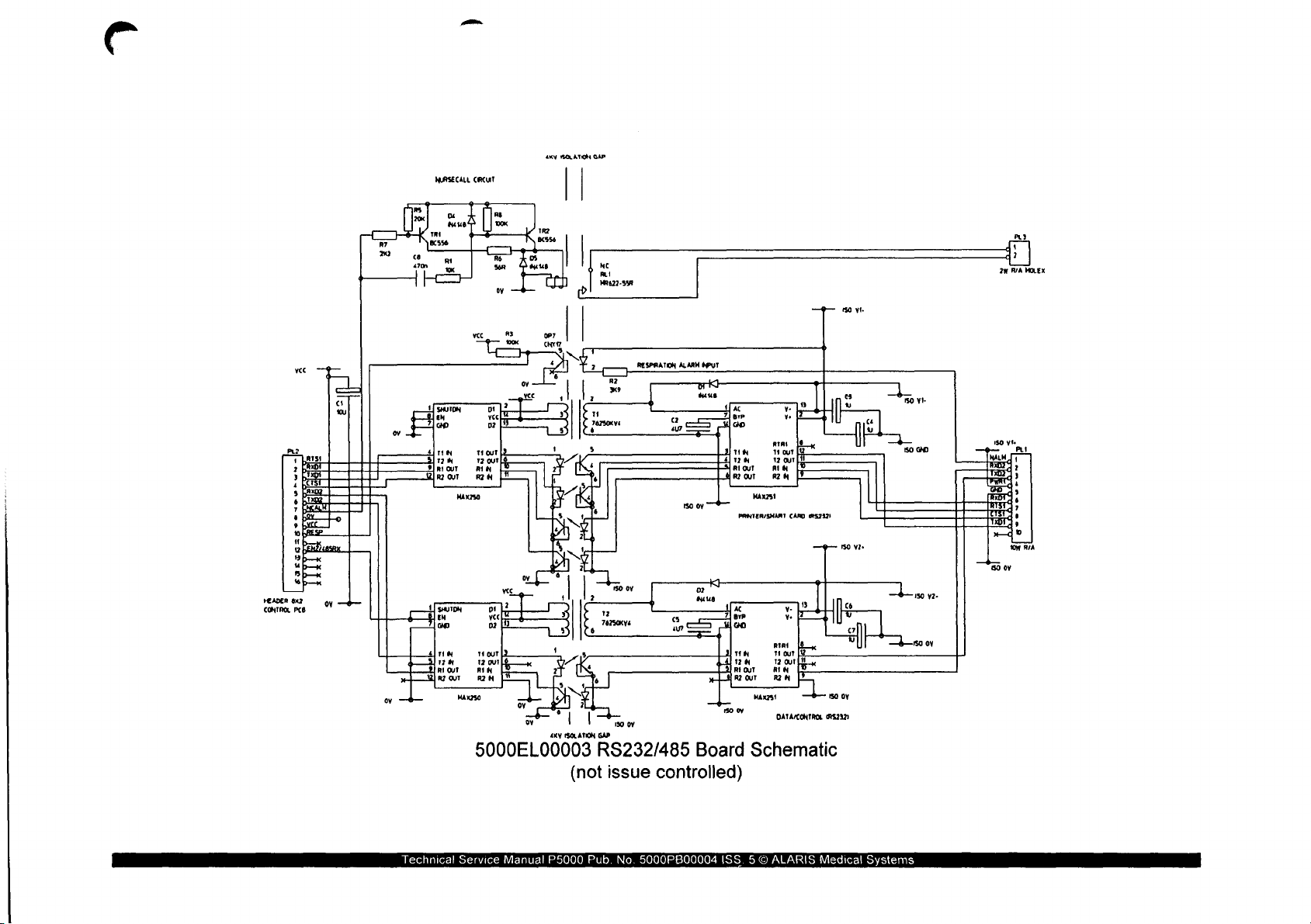
NURSECALL
CIRCUIT
ARN
ISOLATION
| |
GAP
NC
ALI
MR622-S5A
«ΚΝ
R2
x
76250
$
ISOLATION
GAP
RS232/485
(not
issue
RESPRATION
v4
,
130
07
controlled)
1
2
3
4
3
;
φ
o
tt
e
#
“
5
e
R
HEADER
6x2
PCB
ov
5000EL00003
CONTROL
ALARM
APUT
pri
Mus
so
oy 一 一
Board
HN
ZN
RIOUT
т
MAx251
PRINTER/SNARI
AC
yp
o
TIN
28
Rt
OUT
R2
OUT
MAX231
“ão
ov
Schematic
-
Rat
|0
11
our
|
12
out $
RIN
RIM
|?
CARD
5212)
o
v-
Ye
mo
Hour
12
OUT
an | Ji
RN
1
DATACONTROL
—9—
|
Ì
——
We
US
ISO
9152321
es
v
sov.
s
0Y
vt
| u
«
|
mo vi
150
À»
em
d?
20
R/A
GND
у2-
MOLEX
Technical
Service
Manual
P5000
Pub.
No.
5000PB00004
ISS. 5 ©
ALARIS
Medical
Systems
Page 92
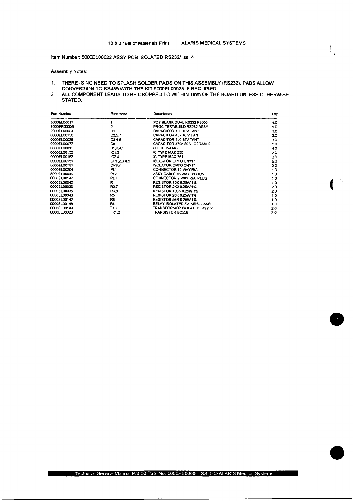
Item
Number:
5000EL00022
13.8.3
ASSY
"Bill
PCB
of
Materials
ISOLATED
Print
RS232/
ALARIS
Iss:
4
MEDICAL
SYSTEMS
Assembly
1.
THERE
CONVERSION
2.
ALL
STATED.
Part
Number
5000EL00017
5000PR00009
0000EL00054
0000EL00150
0000EL00029
0000EL00077
0000EL00016
0000EL00152
0000EL00153
0000EL00151
0000EL00151
0000EL00204
5000EL00049
0000EL00147
0000EL00042
0000EL00036
0000EL00035
0000EL00040
0000EL00142
0000EL00148
0000EL00149
0000EL00020
Notes:
IS
NO
COMPONENT
NEED
TO
TO
RS485
LEADS
Reference
1
2
C1
C2,5,7
C3,4,6
cs
D1,2,4,5
101,3
102,4
0P1,2,3,4,5
OP6,7
PL1
PL2
PL3
RI
R2.7
R3,8
RS
RE
RL1
T1.2
TR1.2
SPLASH
WITH
TO
THE
BE
SOLDER
KIT
CROPPED
PADS
ON
5000EL00028
TO
WITHIN
Description
PCB
BLANK
TEST/BUILD
TYPE
TYPE
CABLE
IN4148
MAX
MAX
OPTO
OPTO
10K
2K2
100K
20K
56R
DUAL
PROC
CAPACITOR
CAPACITOR
CAPACITOR
CAPACITOR
DIODE
IC
IC
ISOLATOR
ISOLATOR
CONNECTOR
ASSY
CONNECTOR
RESISTOR
RESISTOR
RESISTOR
RESISTOR
RESISTOR
RELAY ISOLATED
TRANSFORMER
TRANSISTOR
THIS
ASSEMBLY
IF
REQUIRED.
1mm
OF
RS232
P5000
RS232
10u
4u7
1u0
470n
250
251
10
16
2
BC556
WAY
0.25W
0.25W
0.25W
0.25W
ASSY
16V
TANT
16 V TANT
35V
TANT
50V
CERAMIC
CNY17
CNY17
WAY
R/A
WAY
RIBBON
RIA
PLUG
1%
1%
0.25W
1%
1%
1% 10
5V
MR622-5SR
ISOLATED
RS232
THE
(RS232).
BOARD
UNLESS
PADS
ALLOW
OTHERWISE
3.0
3.0
40
20
2.0
5.0
2.0
10
1.0
10
10
2.0
2.0
1.0
10
2.0
20
Qty
1.0
1.0
10
10
Technical
Service
Manual
P5000
Pub.
No.
5000PB00004
ISS. 5 ©
ALARIS
Medical
Systems
Page 93
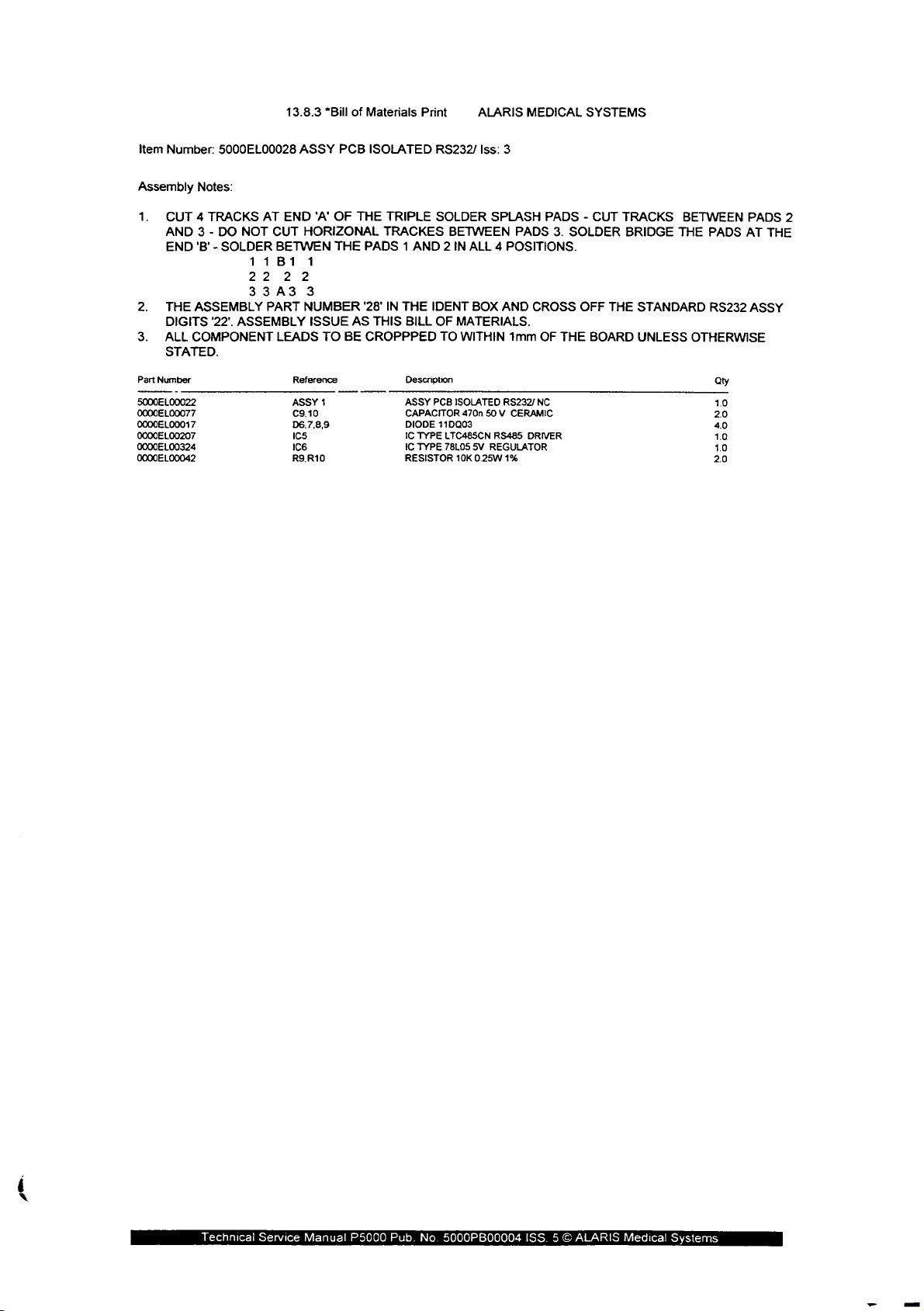
Item
Number:
5000EL00028
13.8.3
ASSY
”Bill
PCB
of
Materials
ISOLATED
Print
RS232/
ALARIS
lss:
3
MEDICAL
SYSTEMS
Assembly
1.
CUT 4 TRACKS
AND 3 -
END
2.
THE
DIGITS
3.
ALL
STATED.
Part
Number
5000EL00022
0000EL00077
0000EL00017
0000EL00207
0000EL00324
0000EL00042
Notes:
DO
NOT
'B' - SOLDER
ASSEMBLY
'22'.
ASSEMBLY
COMPONENT
AT
11B1
22
33A3
PART
END
CUT
BETWEN
22
LEADS
Reference
ASSY
C9,10
D6,7,8,9
Ics
166
R9,R10
‘A’
OF
HORIZONAL
THE
1
3
NUMBER
ISSUE
AS
TO
BE
1
THE
TRIPLE
SOLDER
TRACKES BETWEEN
PADS 1 AND 2 IN
'28'
IN
THE
BILL
Description
ASSY
CAPACITOR
DIODE
IC
TYPE
IC
TYPE
RESISTOR
IDENT
OF
TO
PCB
110003
THIS
CROPPPED
SPLASH
ALL 4 POSITIONS.
BOX
AND
MATERIALS.
WITHIN
ISOLATED
470n
LTC485CN
78L05
10K
RS232/
50 V CERAMIC
RS485
5V
REGULATOR
0.25W
1%
1mm
PADS - CUT
PADS
CROSS
OF
NC
DRIVER
3.
SOLDER
THE
OFF
BOARD
TRACKS
THE
BRIDGE
STANDARD
UNLESS
BETWEEN
THE
PADS
RS232
OTHERWISE
Qty
2.0
40
1.0
20
10
1.0
PADS
AT
ASSY
2
THE
gem.
Technical
Service
Manual
P5000
Pub.
No.
5000PB00004
ISS. 5 ©
ALARIS
Medical
Systems
Page 94

5.7
Flexible
Circuit
Assembly:
1000SP01006
1000SP01006
1000SP01040
1000SP01040
1000SP01007
1000SP01007
See
next
sheet.
Circuit
Bill
of
Materials
Circuit
Bill
of
Materials
Circuit
Bill
of
Materials
Diagram
Diagram
Diagram
(not
(not
(not
(not
(not
(not
issue
issue
issue
issue
issue
issue
controlled)
controlled)
controlled)
controlled)
controlled)
controlled)
Technical
Service
Manual!
P5000
Pub.
No.
5000PB00004
ISS. 5 ©
ALARIS
Medical
Systems
Page 95
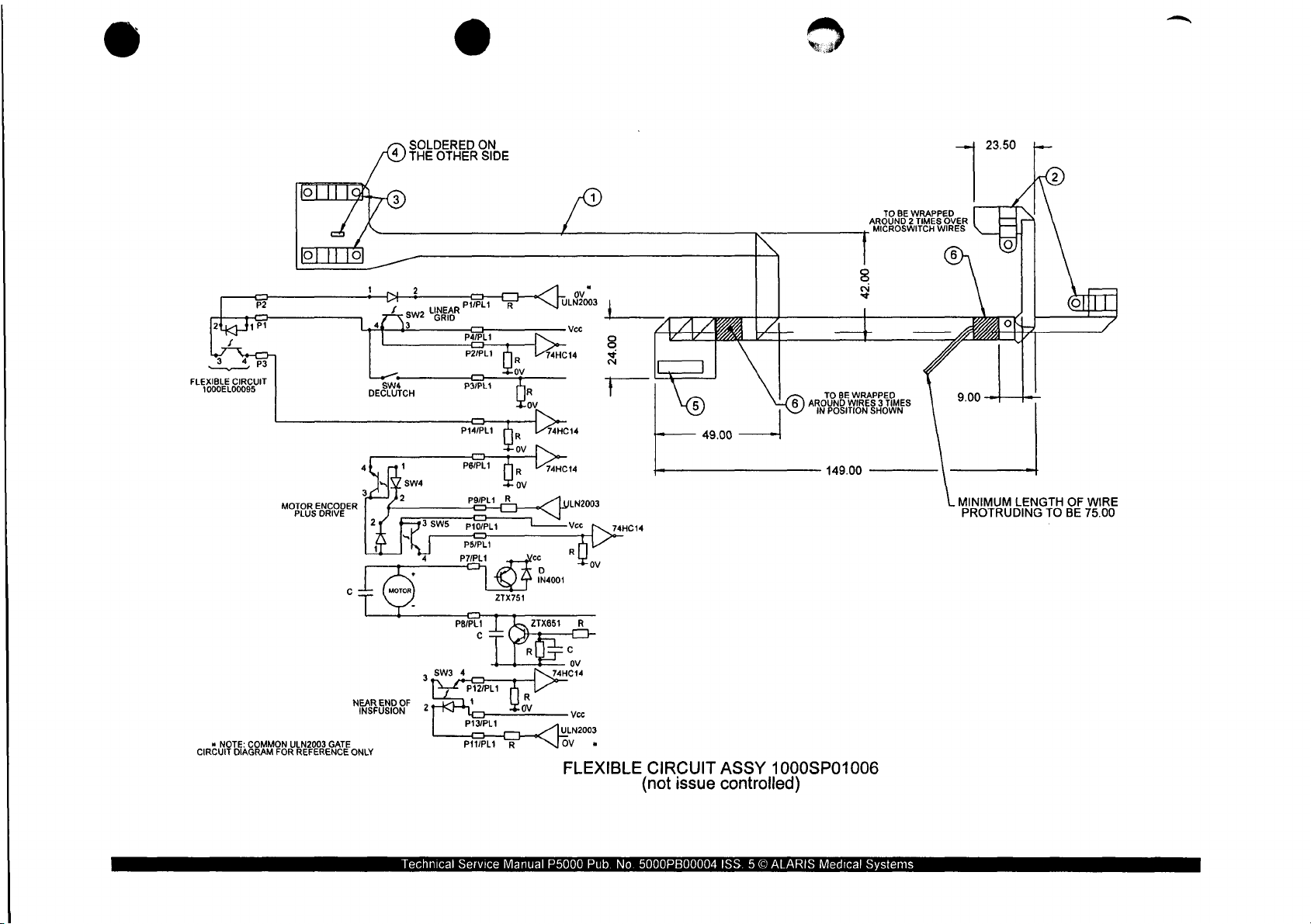
SOLDERED
THE
OTHER
ON
SIDE
2350
e
2
FLEXIBLE
CIRCUIT
1000EL00095
MOTOR
PLUS
ENCODER
DRIVE
了
SW4
DECLUTCH
SW2
3
unear
"GRID
3SW5
PYPLI
PT
P2PL1
PYUPLI
art
=
P14/PL1
PtojPL1
PSIPLI
P7/PL1
C
PBU
16
ον
OF
0
ZTX751
ov
fut
S
ov
/
ULN2003
Vee
aHcia
74HC14
|
24.00
—
74HC14
ALL
o
TO
BE
AROUND 2 TIMES
MICROSWITCH
8
è
~
49.00
TO
AROUND
IN
POSITION
149.00
BE
WRAPPED
WIRES 3 TIMES
SHOWN
WRAPPED
OVER
WIRES
—
'
MINIMUM
PROTRUDING
LENGTH
©
OF
WIRE
TO
BE
75.00
«
NOTE:
CIRCUIT
COMMON
DIAGRAM
FOR
ULN2003
GATE
REFERENCE
NEAR
END
INSFUSION
ONLY
3
OF
2
Technical
P12/PL1
14/Ρ
δα
P11/PL1
Service
Manual
ULN2003
OV
*
FLEXIBLE
P5000
Pub.
(not
No.
5000PB00004
CIRCUIT
issue
ASSY
1000SP01006
controlled)
ISS. 5 ©
ALARIS
Medical
Systems
Page 96

Item
Number:
Part
Number
1000EL00094
0000EL00185
0000EL00003
0000EL00141
0000EL00106
0000ME00238
1000SP01006
Reference
1
2
3
4
5
6
13.8.3
ASSY
*Bill
CIR
of
Materials
FLEXINO.1
Print
Description
OUTLINE
SWITCH
SWITCH
CAPACITOR
CONNECTOR
TAPE
PVC
ALARIS
Iss:
FLEXIBLE
OPTO
SLOTTED
OPTO
SLOTTED
100nF
PLUG
12mm
5
CERAMIC
BLACK
CIRCUIT
SINGLE
DUAL
14
WAY
MEDICAL
CHIP
SYSTEMS
Qty
10
2.0
2.0
10
10
0.1
Technical
Service
Manual
P5000
Pub.
No.
5000PB00004
ISS. 5 ©
ALARIS
Medical
Systems
Page 97

SOLOERED
THE
OTHER
ON
(8)
SIDE
3
——
FLEXIBLE
CIRCUIT
1060EL00095
=
23.50
TO
BE
WRAPPED
A
ROUND 2 TIMES
OVER
MICROSWITCH
WIRES
42.00
TO
IN
WRAPPED
BE
ROUND 3 TIMES
POSITION
SHOWN
NI
(om)
»
NOTE:
COMMON
MOTOR
.
_
PLUS
Bo
ULN2003
ENCODER
DRIVE
L1
INN
A
L2
GATE
Technical
Service
P11
Manual
P5000
Pub.
FLEXIBLE
No.
5000PB00004
CIRCUIT
(not
ASSEMBLY
issue
ISS. 5 ©
controlled)
ALARIS
1000SP01040
Medical
149.00
Systems
MINIMUM
LE
NGTH
OTRUDING
E
75.00
OF
WIRE
PR
Page 98
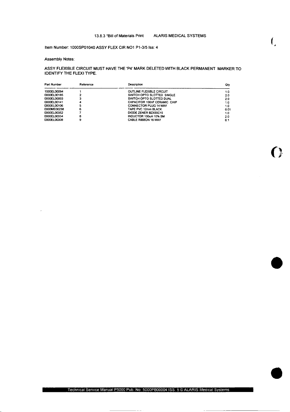
Item
Number:
1000SP01040
13.8.3
ASSY
*Bill
FLEX
of
Materials
CIR
NO1
Print
P1-3/5
ALARIS
Iss:
MEDICAL
SYSTEMS
4
Assembly
ASSY
IDENTIFY
Part
Number
1000EL00094
0000EL00185
0000EL00003
0000EL00141
0000EL00106
0000ME00238
0000EL00352
0000EL00334
0000EL00308
Notes:
FLEXIBLE
THE
CIRCUIT
FLEXI
Reference
1
2
3
4
5
6
7
8
9
TYPE.
MUST
HAVE
THE
'P4'
MARK
Description
OUTLINE
SWITCH
SWITCH
CAPACITOR
CONNECTOR
TAPE
PVC
DIODE
ZENER
INDUCTOR
CABLE
RIBBON
DELETED
FLEXIBLE
OPTO
OPTO
100nF
PLUG
12mm
100uH
CIRCUIT
SLOTTED
SLOTTED
CERAMIC
14
BLACK
BZX55C15
10%
16
WAY
WAY
SM
WITH
SINGLE
DUAL
CHIP
BLACK
PERMANENT
MARKER
Qty
1.0
20
20
1.0
1.0
0.01
1.0
20
0.1
TO
Technical
Service
Manual
P5000
Pub.
No.
5000PB00004
ISS. 5 O
ALARIS
Medical
Systems
Page 99

FOLD
FLEXIBLE
CIRCUIT
NOTES:
1.
2.
THRO'
FOLD
USE
ON
LOW
180°
SILKSCREEN
MELTING
FOLD
POINT
LINES
SOLDER
ON
ALL
COMPONENTS
(179°C)
FOLD
TO
BE
THRO'
90°
ONLY
FLEXIBLE
Technical
Service
CIRCUIT
(not
issue
Manual
P5000
ASSEMBLY
controlled)
Pub.
No.
5000PB00004
1000SP01007
ISS. 5 ©
ALARIS
Medical
Systems
Page 100

Item
Number:
Part
Number
1000EL00095
0000EL00185
1000SP01007
Reference
1
2
13.8.3
ASSY
*Bill
of
CIR
Materials
FLEXINO.2
Description
FLEXIBLE
SWITCH
Print
OPTO
ALARIS
1ss:
2
CIRCUIT
SLOTTED
PLUNGER
SINGLE
MEDICAL
SYSTEMS
Qty
1.0
1.0
Technical
Service
Manual
P5000
Pub.
No.
5000PB00004
ISS. 5 ©
ALARIS
Medical
Systems
 Loading...