

Page 1

Software User Manual
Field Maintenance Software Version 5.0
MedSystem III® Infusion Pump
Model 286X
Alaris® Products
June 2006
Page 2

GENERAL CONTACT INFORMATION
Cardinal Health
Alaris® Products
10221 Wateridge Circle
San Diego, California 92121
http://www.cardinalhealth.com/alaris
Customer Advocacy
Clinical and technical feedback.
North America:
Phone: 800.854.7128, Ext. 7812
E-Mail: CustomerFeedback@cardinal.com
Technical Support - North America
Maintenance, service information support, and troubleshooting.
United States - Phone:
858.458.6003
800.854.7128, Ext. 6003
Within Canada: 800.387.8309
From United States: 800.908.9918
Canada - Phone:
Customer Care - North America
Instrument return, service assistance, and order placement.
United States - Phone: 800.482.4822 Canada - Phone: 800.387.8309
Page 3

Table of Contents
INTRODUCTION
ABOUT FMS. . . . . . . . . . . . . . . . . . . . . . . . . . . . . . . . . . . . . . . . . . . . . . . . . . . . . . . . . . . . . . . . . . . . . . . . . . . . . . . . . . . . . . . . . . . . . . . . . . . . 1
WARNINGS AND CAUTIONS
Definitions . . . . . . . . . . . . . . . . . . . . . . . . . . . . . . . . . . . . . . . . . . . . . . . . . . . . . . . . . . . . . . . . . . . . . . . . . . . . . . . . . . . . . . . . . . . . . . . . 2
Warnings
Cautions
. . . . . . . . . . . . . . . . . . . . . . . . . . . . . . . . . . . . . . . . . . . . . . . . . . . . . . . . . . . . . . . . . . . . . . . . . . . . . . . . . . . . . . . . . . . . . . . . . . 2
. . . . . . . . . . . . . . . . . . . . . . . . . . . . . . . . . . . . . . . . . . . . . . . . . . . . . . . . . . . . . . . . . . . . . . . . . . . . . . . . . . . . . . . . . . . . . . . . . . 2
SOFTWARE REVISION HIGHLIGHTS
ABBREVIATIONS/ACRONYMS
COMMANDS/DEFINITIONS
INSTRUMENT PROGRAMMING AND FMS FUNCTIONS
Instrument Programming
Calibration Functions. . . . . . . . . . . . . . . . . . . . . . . . . . . . . . . . . . . . . . . . . . . . . . . . . . . . . . . . . . . . . . . . . . . . . . . . . . . . . . . . . . . . 7
Event, Alarm, and Status Log Functions
Other FMS Functions . . . . . . . . . . . . . . . . . . . . . . . . . . . . . . . . . . . . . . . . . . . . . . . . . . . . . . . . . . . . . . . . . . . . . . . . . . . . . . . . . . . 8
INSTALLATION AND SETUP
SYSTEM REQUIREMENTS . . . . . . . . . . . . . . . . . . . . . . . . . . . . . . . . . . . . . . . . . . . . . . . . . . . . . . . . . . . . . . . . . . . . . . . . . . . . . . . . . . 9
Hardware . . . . . . . . . . . . . . . . . . . . . . . . . . . . . . . . . . . . . . . . . . . . . . . . . . . . . . . . . . . . . . . . . . . . . . . . . . . . . . . . . . . . . . . . . . . . . . . . . 9
Software
SOFTWARE INSTALLATION
Unpacking FMS Kit . . . . . . . . . . . . . . . . . . . . . . . . . . . . . . . . . . . . . . . . . . . . . . . . . . . . . . . . . . . . . . . . . . . . . . . . . . . . . . . . . . . . . . 9
Installing Software . . . . . . . . . . . . . . . . . . . . . . . . . . . . . . . . . . . . . . . . . . . . . . . . . . . . . . . . . . . . . . . . . . . . . . . . . . . . . . . . . . . . . . . 10
Cable Hookup
Uninstalling Software
Checking Installed Software Version. . . . . . . . . . . . . . . . . . . . . . . . . . . . . . . . . . . . . . . . . . . . . . . . . . . . . . . . . . . . . . . . . . 12
. . . . . . . . . . . . . . . . . . . . . . . . . . . . . . . . . . . . . . . . . . . . . . . . . . . . . . . . . . . . . . . . . . . . . . . . . . . . . . . . . . . . . . . . . . . . . . . . . . 9
. . . . . . . . . . . . . . . . . . . . . . . . . . . . . . . . . . . . . . . . . . . . . . . . . . . . . . . . . . . . . . . . . . . . . . . . . . . . . . . . . . . . . . . . . . . . 11
. . . . . . . . . . . . . . . . . . . . . . . . . . . . . . . . . . . . . . . . . . . . . . . . . . . . . . . . . . . . . . . . . . . . . . . . . . . . . . . . 2
. . . . . . . . . . . . . . . . . . . . . . . . . . . . . . . . . . . . . . . . . . . . . . . . . . . . . . . . . . . . . . . . . . . . . 3
. . . . . . . . . . . . . . . . . . . . . . . . . . . . . . . . . . . . . . . . . . . . . . . . . . . . . . . . . . . . . . . . . . . . . . . . . . . . . . 4
. . . . . . . . . . . . . . . . . . . . . . . . . . . . . . . . . . . . . . . . . . . . . . . . . . . . . . . . . . . . . . . . . . . . . . . . . . . . . . . . . . 5
. . . . . . . . . . . . . . . . . . . . . . . . . . . . . . . . . . . . . . . . . . . . . . . 7
. . . . . . . . . . . . . . . . . . . . . . . . . . . . . . . . . . . . . . . . . . . . . . . . . . . . . . . . . . . . . . . . . . . . . . . . . . . . . . . 7
. . . . . . . . . . . . . . . . . . . . . . . . . . . . . . . . . . . . . . . . . . . . . . . . . . . . . . . . . . . . . . 8
. . . . . . . . . . . . . . . . . . . . . . . . . . . . . . . . . . . . . . . . . . . . . . . . . . . . . . . . . . . . . . . . . . . . . . . . . . . . . . . . . 9
. . . . . . . . . . . . . . . . . . . . . . . . . . . . . . . . . . . . . . . . . . . . . . . . . . . . . . . . . . . . . . . . . . . . . . . . . . . . . . . . . . . . 11
STARTING FMS
GENERAL INFORMATION . . . . . . . . . . . . . . . . . . . . . . . . . . . . . . . . . . . . . . . . . . . . . . . . . . . . . . . . . . . . . . . . . . . . . . . . . . . . . . . . . . . 13
Running FMS
Main Menu Options
Serial Port Setup
General Page Layout
On-line Help
Automatic Maintenance Mode Recognition
. . . . . . . . . . . . . . . . . . . . . . . . . . . . . . . . . . . . . . . . . . . . . . . . . . . . . . . . . . . . . . . . . . . . . . . . . . . . . . . . . . . . . . . . . . . . . 13
. . . . . . . . . . . . . . . . . . . . . . . . . . . . . . . . . . . . . . . . . . . . . . . . . . . . . . . . . . . . . . . . . . . . . . . . . . . . . . . . . . . . . . 14
. . . . . . . . . . . . . . . . . . . . . . . . . . . . . . . . . . . . . . . . . . . . . . . . . . . . . . . . . . . . . . . . . . . . . . . . . . . . . . . . . . . . . . . . 16
. . . . . . . . . . . . . . . . . . . . . . . . . . . . . . . . . . . . . . . . . . . . . . . . . . . . . . . . . . . . . . . . . . . . . . . . . . . . . . . . . . . . 17
. . . . . . . . . . . . . . . . . . . . . . . . . . . . . . . . . . . . . . . . . . . . . . . . . . . . . . . . . . . . . . . . . . . . . . . . . . . . . . . . . . . . . . . . . . . . . . 18
. . . . . . . . . . . . . . . . . . . . . . . . . . . . . . . . . . . . . . . . . . . . . . . . . . . . . . . . . . 19
FIELD MAINTENANCE SOFTWARE
CUSTOMIZING PARAMETERS: INSTRUMENT CONFIGURATION MODE . . . . . . . . . . . . . . . . . . . . . . . . . . 21
Custom Instrument Configurations
Reset Faults (Selection 00)
Clear Instrument Logs (Selection 01)
Reset Rate, VR, and Time to Default Values (Selection 02)
Set Instrument Serial Number (Selection 03)
Set User Information Line (Selection 04)
Special Note Message / Enable / Set Date (Selection 05, 06, 07)
Clear Battery Installation Dates and Clear Battery Log (Selection 08, 09)
. . . . . . . . . . . . . . . . . . . . . . . . . . . . . . . . . . . . . . . . . . . . . . . . . . . . . . . . . . . . . . . . . . . . 21
. . . . . . . . . . . . . . . . . . . . . . . . . . . . . . . . . . . . . . . . . . . . . . . . . . . . . . . . . . . . . . . . . . . . . . . . . . . . 21
. . . . . . . . . . . . . . . . . . . . . . . . . . . . . . . . . . . . . . . . . . . . . . . . . . . . . . . . . . . . . . . . . 22
. . . . . . . . . . . . . . . . . . . . . . . . . . . . . . . . . . . . . . . 22
. . . . . . . . . . . . . . . . . . . . . . . . . . . . . . . . . . . . . . . . . . . . . . . . . . . . . . . . 23
. . . . . . . . . . . . . . . . . . . . . . . . . . . . . . . . . . . . . . . . . . . . . . . . . . . . . . . . . . . . . 23
. . . . . . . . . . . . . . . . . . . . . . . . . . . . . . . . 24
. . . . . . . . . . . . . . . . . . . . . . . 25
Field Maintenance Software
Model 286X, v5.0
Software User Manual
Table of Contents i
Page 4

FIELD MAINTENANCE SOFTWARE (CONTINUED)
CUSTOMIZING PARAMETERS: INSTRUMENT CONFIGURATION MODE (CONTINUED)
Reset Device Specific Parameters (Selection 10)
Enable/Disable ClrAir Softkey (Selection 11)
Change Rate Breakpoint for ClrAir Softkey (Selection 12)
Lock/Unlock Dose Rate Calculator (Selection 13)
Set Keep Vein Open Rate (Selection 14)
. . . . . . . . . . . . . . . . . . . . . . . . . . . . . . . . . . . . . . . . . . . . . . . . . . . . . . . . . . . . . 26
Set Maximum Primary Rate (Selection 15). . . . . . . . . . . . . . . . . . . . . . . . . . . . . . . . . . . . . . . . . . . . . . . . . . . . . . . . . . . 26
Set Maximum Primary Volume Remaining (Selection 16)
Set Maximum Secondary Rate (Selection 17)
Set Maximum Secondary Volume Remaining (Selection 18)
Enable/Disable Audio Volume Ramping (Selection 19)
Set OFF Delay (Selection 20)
. . . . . . . . . . . . . . . . . . . . . . . . . . . . . . . . . . . . . . . . . . . . . . . . . . . . . . . . . . . . . . . . . . . . . . . . . . 29
Set Main Battery Installation Date (Selection 21)
Set Memory-Backup Battery Installation Date (Selection 22)
Set Fractional Scrolling Breakpoint (General Purpose II and Operating Room II only) 3
(Selection 23)
. . . . . . . . . . . . . . . . . . . . . . . . . . . . . . . . . . . . . . . . . . . . . . . . . . . . . . . . . . . . . . . . . . . . . . . . . . . . . . . . . . . . . . . . . . . . 31
Lock/Unlock Device Type Change (Selection 24)
Lock/Unlock IVPB (Selection 25)
. . . . . . . . . . . . . . . . . . . . . . . . . . . . . . . . . . . . . . . . . . . . . . . . . . . . . . . . . . . . . . . . . . . . . . 32
Enable/Disable ALL Settings for VR (Selection 26)
Set Air-in-Line Alarm Sensitivity (Selection 27) . . . . . . . . . . . . . . . . . . . . . . . . . . . . . . . . . . . . . . . . . . . . . . . . . . . . . . 33
Set Incremental Pressure (Selection 28)
Set Maximum Pressure (Selection 29)
. . . . . . . . . . . . . . . . . . . . . . . . . . . . . . . . . . . . . . . . . . . . . . . . . . . . . . . . . . . . . 34
. . . . . . . . . . . . . . . . . . . . . . . . . . . . . . . . . . . . . . . . . . . . . . . . . . . . . . . . . . . . . . . . 35
Lock/Unlock Dose Parameters (Selection 30)
Reset Configuration Data (Selection 31)
INSTRUMENT PROGRAMMING
Dose Calculator
Batch Programming
CALIBRATION
Calibration Options
Calibration Prerequisites
Starting Calibration
Full Calibration
. . . . . . . . . . . . . . . . . . . . . . . . . . . . . . . . . . . . . . . . . . . . . . . . . . . . . . . . . . . . . . . . . . . . . . . . . . . . . . . . . . . . . . . . . . 36
. . . . . . . . . . . . . . . . . . . . . . . . . . . . . . . . . . . . . . . . . . . . . . . . . . . . . . . . . . . . . . . . . . . . . . . . . . . . . . . . . . . . . 37
. . . . . . . . . . . . . . . . . . . . . . . . . . . . . . . . . . . . . . . . . . . . . . . . . . . . . . . . . . . . . . . . . . . . . . . . . . . . . . . . . . . . . . . . . . . . . . . . . . 38
. . . . . . . . . . . . . . . . . . . . . . . . . . . . . . . . . . . . . . . . . . . . . . . . . . . . . . . . . . . . . . . . . . . . . . . . . . . . . . . . . . . . . . 39
. . . . . . . . . . . . . . . . . . . . . . . . . . . . . . . . . . . . . . . . . . . . . . . . . . . . . . . . . . . . . . . . . . . . . . . . . . . . . . . . 41
. . . . . . . . . . . . . . . . . . . . . . . . . . . . . . . . . . . . . . . . . . . . . . . . . . . . . . . . . . . . . . . . . . . . . . . . . . . . . . . . . . . . . . 42
. . . . . . . . . . . . . . . . . . . . . . . . . . . . . . . . . . . . . . . . . . . . . . . . . . . . . . . . . . . . . . . . . . . . . . . . . . . . . . . . . . . . . . . . . . . 42
Cassette/Latch Sensor/OPSI Calibration
Patient-side Occlusion Calibration
Fluid-side Occlusion Calibration
Calibration Data Menu
. . . . . . . . . . . . . . . . . . . . . . . . . . . . . . . . . . . . . . . . . . . . . . . . . . . . . . . . . . . . . . . . . . . . . . . . . . . . . . . . . . 48
Full Calibration Information Menu
Exiting Calibration Menu
LOGS MENU
. . . . . . . . . . . . . . . . . . . . . . . . . . . . . . . . . . . . . . . . . . . . . . . . . . . . . . . . . . . . . . . . . . . . . . . . . . . . . . . . . . . . . . . . . . . . . . . . . . . 53
Storing a Log to File
Displaying a Log
Printing a Log
Exiting Logs Menu
. . . . . . . . . . . . . . . . . . . . . . . . . . . . . . . . . . . . . . . . . . . . . . . . . . . . . . . . . . . . . . . . . . . . . . . . . . . . . . . . . . . . . . . . . 57
. . . . . . . . . . . . . . . . . . . . . . . . . . . . . . . . . . . . . . . . . . . . . . . . . . . . . . . . . . . . . . . . . . . . . . . . . . . . . . . . . . . . . . . . . . . . 58
. . . . . . . . . . . . . . . . . . . . . . . . . . . . . . . . . . . . . . . . . . . . . . . . . . . . . . . . . . . . . . . . . . . . . . . . . . . . . . . . 52
. . . . . . . . . . . . . . . . . . . . . . . . . . . . . . . . . . . . . . . . . . . . . . . . . . . . . . . . . . . . . . . . . . . . . . . . . . . . . . . . . . . . . 54
. . . . . . . . . . . . . . . . . . . . . . . . . . . . . . . . . . . . . . . . . . . . . . . . . . . . . . . . . . . . . . . . . . . . . . . . . . . . . . . . . . . . . . . 58
. . . . . . . . . . . . . . . . . . . . . . . . . . . . . . . . . . . . . . . . . . . . . . . . . . . . . . . . . . . . . . . . . . . . . . . . . . . . 36
. . . . . . . . . . . . . . . . . . . . . . . . . . . . . . . . . . . . . . . . . . . . . . . . . . . . . . . . . . . . . . . . . . . . . . . 46
. . . . . . . . . . . . . . . . . . . . . . . . . . . . . . . . . . . . . . . . . . . . . . . . . . . . . . . . . . . . . 35
. . . . . . . . . . . . . . . . . . . . . . . . . . . . . . . . . . . . . . . . . . . . . . . . . . . . . . . . . . . . . 43
. . . . . . . . . . . . . . . . . . . . . . . . . . . . . . . . . . . . . . . . . . . . . . . . . . . . . . . . . . . . . . . . . . . . . 44
. . . . . . . . . . . . . . . . . . . . . . . . . . . . . . . . . . . . . . . . . . . . . . . . . . . . . . . . . . . . . . . . . . . . . 50
EXITING FMS . . . . . . . . . . . . . . . . . . . . . . . . . . . . . . . . . . . . . . . . . . . . . . . . . . . . . . . . . . . . . . . . . . . . . . . . . . . . . . . . . . . . . . . . . . . . . . . . . . 58
. . . . . . . . . . . . . . . . . . . . . . . . . . . . . . . . . . . . . . . . . . . . . . . . . . . 25
. . . . . . . . . . . . . . . . . . . . . . . . . . . . . . . . . . . . . . . . . . . . . . . . . . . . . . . . 25
. . . . . . . . . . . . . . . . . . . . . . . . . . . . . . . . . . . . . . . . . 26
. . . . . . . . . . . . . . . . . . . . . . . . . . . . . . . . . . . . . . . . . . . . . . . . . . . 26
. . . . . . . . . . . . . . . . . . . . . . . . . . . . . . . . . . . . . . . . . . 28
. . . . . . . . . . . . . . . . . . . . . . . . . . . . . . . . . . . . . . . . . . . . . . . . . . . . . . . 28
. . . . . . . . . . . . . . . . . . . . . . . . . . . . . . . . . . . . . . 29
. . . . . . . . . . . . . . . . . . . . . . . . . . . . . . . . . . . . . . . . . . . . . 29
. . . . . . . . . . . . . . . . . . . . . . . . . . . . . . . . . . . . . . . . . . . . . . . . . . . . 30
. . . . . . . . . . . . . . . . . . . . . . . . . . . . . . . . . . . . . . 30
. . . . . . . . . . . . . . . . . . . . . . . . . . . . . . . . . . . . . . . . . . . . . . . . . . . 31
. . . . . . . . . . . . . . . . . . . . . . . . . . . . . . . . . . . . . . . . . . . . . . . . . 32
. . . . . . . . . . . . . . . . . . . . . . . . . . . . . . . . . . . . . . . . . . . . . . . . . . . . . . . 35
ii Table of Contents
Field Maintenance Software
Model 286X, v5.0
Software User Manual
Page 5

APPENDIX
PARAMETER VERIFICATION PROCEDURES. . . . . . . . . . . . . . . . . . . . . . . . . . . . . . . . . . . . . . . . . . . . . . . . . . . . . . . . . . . . 59
Verification Procedure A
Verification Procedure B
Verification Procedure C
Verification Procedure D
SERVICE INFORMATION
Technical Support . . . . . . . . . . . . . . . . . . . . . . . . . . . . . . . . . . . . . . . . . . . . . . . . . . . . . . . . . . . . . . . . . . . . . . . . . . . . . . . . . . . . . . . 61
Software Return
. . . . . . . . . . . . . . . . . . . . . . . . . . . . . . . . . . . . . . . . . . . . . . . . . . . . . . . . . . . . . . . . . . . . . . . . . . . . . . . . . . . . . . . . . 61
TRADEMARKS. . . . . . . . . . . . . . . . . . . . . . . . . . . . . . . . . . . . . . . . . . . . . . . . . . . . . . . . . . . . . . . . . . . . . . . . . . . . . . . . . . . . . . . . . . . . . . . . . 61
. . . . . . . . . . . . . . . . . . . . . . . . . . . . . . . . . . . . . . . . . . . . . . . . . . . . . . . . . . . . . . . . . . . . . . . . . . . . . . . . 59
. . . . . . . . . . . . . . . . . . . . . . . . . . . . . . . . . . . . . . . . . . . . . . . . . . . . . . . . . . . . . . . . . . . . . . . . . . . . . . . 59
. . . . . . . . . . . . . . . . . . . . . . . . . . . . . . . . . . . . . . . . . . . . . . . . . . . . . . . . . . . . . . . . . . . . . . . . . . . . . . . 60
. . . . . . . . . . . . . . . . . . . . . . . . . . . . . . . . . . . . . . . . . . . . . . . . . . . . . . . . . . . . . . . . . . . . . . . . . . . . . . . 60
. . . . . . . . . . . . . . . . . . . . . . . . . . . . . . . . . . . . . . . . . . . . . . . . . . . . . . . . . . . . . . . . . . . . . . . . . . . . . . . . . . . . 61
Field Maintenance Software
Model 286X, v5.0
Software User Manual
Table of Contents iii
Page 6

THIS PAGE
INTENTIONALLY
LEFT BLANK
iv Table of Contents
Field Maintenance Software
Model 286X, v5.0
Software User Manual
Page 7

Introduction
Product Notification:
• Documentation provided with this product may reference product(s) not present in
your facility or not yet available for sale in your area.
• Field Maintenance Software (FMS) User Manual is designed to assist Biomedical
personnel in customizing the MedSystem III
®
infusion pump (instrument) to meet
special needs of their institutions.
• Main text discusses different features of FMS and how to initiate them. Appendices
provide additional information for instrument Configuration, Calibration, and Log
Menu pages.
• All KEY NAMES are written in regular type as they appear on instrument or computer
keyboard. All SCREEN MESSAGES are as they appear on screen, except they are
in italic type, and Menu Titles are in regular type with only first letters capitalized.
• For more information on other MedSystem III
®
infusion pump features, refer to
instrument Directions for Use (DFU).
About FMS
This software is provided under and subject to a license from Cardinal Health.
Presented herein is a detailed description of FMS, a program that runs on a personal
computer (PC) running Windows 2000 or Windows XP. This program assists
organizations in servicing and customizing configuration of instrument. This manual is to
be used only with instrument software versions 4.0 or higher.
Field Maintenance Software
Model 286X, v5.0
Software User Manual
Introduction 1
Page 8

Warnings and Cautions
WARNING
A
is an alert to a potential hazard which could result in serious personal
injury and/or product damage if proper procedures are not followed.
CAUTION
A
is an alert to a potential hazard which could result in minor personal
injury and/or product damage if proper procedures are not followed.
WARNINGS
• At no time should FMS be used to configure instrument while it is connected to a
patient.
• Ensure instrument is in operational status before returning it to patient use.
• FMS version 5.0 is not compatible with instrument software versions 3.0 and 3.5
CAUTIONS
Hospital policies and procedures should be consulted when determining appropriate
air-in-line thresholds. As a general guideline, set lowest thresholds appropriate when
patient susceptibility to infused air is an important consideration.
2 Introduction
Field Maintenance Software
Model 286X, v5.0
Software User Manual
Page 9

Software Revision Highlights
Below are examples of differences between FMS Dos version 2.24 and FMS Windows
version 5.0. User interface changes have also occurred due to differences in systems.
DOS Windows
If more than one configuration function is
executed, FMS prompts user to save a
configuration file. If only one function is
executed FMS will NOT prompt user to
save a configuration file.
User can not change directory when
saving a file.
An option is selected either by using up or
down arrow keys on computer keyboard to
highlight desired option, or by typing fi rst
character of desired option (such as L to
select Logs Menu).
A selected option is executed by pressing
enter key.
No delay in establishing and ending
communications between instrument and
computer.
If one or more configuration function is
exectued, FMS prompts user to save
configuration file.
User can choose which directory to save
fi le in.
An option is selected by clicking it with
mouse.
A selected option is executed by clicking
ok button on screen with mouse.
A slight delay in establishing and ending
communications between instrument
and computer due to a more robust
communication method.
Navigating menu items can only be
accomplished when establishing
communication with instrument.
2 COM port options available, COM1 and
COM2.
Reports are navigated using only up or
down arrows.
Field Maintenance Software
Model 286X, v5.0
Software User Manual
Navigating menu items can be
accomplished with or without establishing
communication with instrument.
8 COM port options available, COM1
through COM8.
Reports are navigated using horizontal
and vertical scroll bars.
Introduction 3
Page 10

Abbreviations / Acronyms
CIDLIP Cassette Indentifi cation/Latch in Place
ClrAir Clear Air
COM Communications
CP Controller Pressure
DRC Dose Rate Calculator
FMS Field Maintenance Software
GP General Purpose
GP2 General Purpose II
GPII General Purpose II
IBM International Business Machines
ID Identifi cation
KVO Keep Vein Open
LCD Liquid Crystal Display
NN Neonatal
NiCd Nickel Cadmium
OR Operating Room
OR2 Operating Room II
ORII Operating Room II
PC Personal Computer
PSOD Patient Side Occlusion Detection
vol Volume
VR Volume Remaining
4 Introduction
Field Maintenance Software
Model 286X, v5.0
Software User Manual
Page 11

Commands / Definitions
With FMS, user can customize configuration of instrument from a menu of parameters.
User highlights a selected Configuration Command on Instrument Configuration
Command Menu, and then places instrument in Maintenance Mode by following
directions on screen.
This list of commands will be displayed as follows:
00 Reset Faults - Allows pump channel to be reset from Service to an operational
status.
01 Clear Log - Allows user to clear all entries in internal Event, Status, or Alarm Log.
02 Reset Rate, Volume Remaining, Time Remaining - Resets rate, VR, and time
remaining to factory default settings. This should be used in event of a Watchdog
(30,x) Range Error.
03 Set Instrument Serial Number - Allows user to enter instrument serial number
for display on User Information and Instrument Settings pages.
04 Set User Information Line - Allows an institution to enter their ID number, code,
or name for display on User Information page. Limited to 25 characters including
spaces.
05 Enable/Disable Special Notes - Allows user to enable/disable Special Note
page feature.
06 Set Date To Display Special Note - Allows user to set date for Special Notes page.
Page displays every time instrument is turned on.
07 Set Special Note Messages - Allows user to enter up to five lines of text, 27
characters per line including spaces on Special Notes page.
08 Clear Main Battery Date - Allows main battery installation date and Battery
Log to be cleared.
09 Clear Backup Battery Date - Allows only backup battery installation date to be
cleared.
10 Reset Device Specific Parameters - Automatically resets all device type specific
parameters in instrument to factory default values.
11 Enable/Disable ClrAir Softkey - Allows user to enable/disable ClrAir
softkey for a specific device type.
12 Change Rate Breakpoint for ClrAir - Allows user to set a specific device type and
specific Clear Air rate breakpoint, below which ClrAir softkey is not available.
13 Lock/Unlock Dose Rate Calculator - Allows user to lock out Dose Rate
Calculator feature.
14 Set KVO Rate for Device Type - Set Keep Vein Open (KVO) Rate for a specific
device type, which occurs following an Infusion Complete Advisory.
Field Maintenance Software
Model 286X, v5.0
Software User Manual
Introduction 5
Page 12

Commands / Definitions (Continued)
15 Set Maximum Rate for Device Type - Set maximum limit for Primary infusion rates
for a specific device type.
16 Set Maximum VR for Device Type - Set maximum limit for Primary VR for a
specific device type.
17 Set Max Secondary Rate for Device - Set maximum limit for Secondary infusion
rates for a specific device type.
18 Set Max Secondary VR for Device - Set maximum limit for Secondary VR for a
specific device type.
19 Enable/Disable Audio Ramping - Allows automatic ramping of alarm audio
volume to be enabled or disabled when alarms are ignored.
20 Set Instrument Off Delay (1, 3, 5, 10 seconds) - Allows user to set period of
time that OFF key must be pressed and held to turn off instrument.
21 Set Main Battery Install Date - Allows instrument’s memory to maintain date NiCd
battery pack was last changed.
22 Set Backup Battery Install Date - Allows instrument’s memory to maintain date
memory-backup battery was last changed.
23 Set Fractional Scrolling Breakpt - Allows user to set breakpoint at which
VR and Rate change from increments of tenths of a milliliter (0.1) to increments of 1
milliliter (1.0) (for General Purpose II and Operating Room II device types only).
24 Lock/Unlock Device Type Change - Allows instrument to be locked in current
device type.
25 Lock/Unlock IVPB - Allows all three channels to be locked in current channel
mode (such as, Basic, Dual Rate).
26 Enable/Disable ALL Setting for VR - Allows a channel to infuse until container is
empty, rather than infusing a set volume remaining (VR) (applicable for Operating
Room and Operating Room II device types only).
27 Set Air-in-Line Alarm Sensitivity - Set threshold at which an Air-in-Line alarm occurs
for a specific device type.
28 Set Pressure Increment - Set incremental pressure over baseline at which a
Patient-side Occlusion alarm occurs for a specific device type.
29 Set Maximum Pressure - Sets maximum pressure at which a Patient-side
Occlusion alarm occurs.
30 Lock/Unlock Dose Parameters - Allows user to access and change drug
concentration and dose rate units for all drugs.
31 Reset Instrument Configuration Data - Automatically resets non-device type specific
instrument configuration parameters to factory default settings, including rate, VR
and time.
6 Introduction
Field Maintenance Software
Model 286X, v5.0
Software User Manual
Page 13

Instrument Programming and FMS Functions
Instrument Programming
Programming Menu is available from Main Menu by highlighting Instrument
Programming. The following selections are displayed:
• Dose Rate Calculator - Allows user to select and program a Dose Rate Calculator
Drug Table confi guration to an instrument.
• Batch Programming - Allows user to execute a set of confi guration commands by
selecting a Batch Programming fi le, then reviewing and executing sequential
commands in fi le.
• Quit Programming - Returns user to Main Menu.
Calibration Functions
Calibration data can be stored, displayed, or printed by using appropriate FMS
commands.
Calibration operations provided by FMS:
• Full Calibration (all channels)
• Cassette/Latch Sensor Calibration (all channels)
• Patient-Side Occlusion Calibration (all channels)
• Fluid-Side Occlusion Calibration (all channels)
• Single Calibration Menu (single channel)
• Calibration Data Menu
• Full Calibration Information
• Quit Calibration
Field Maintenance Software
Model 286X, v5.0
Software User Manual
Introduction 7
Page 14

Instrument Programming and FMS Functions (Continued)
Event, Alarm, and Status Log Function
Logs Menu functions provided by FMS:
• Retrieves Event, Status, Alarm, or All Logs from instrument and stores it to a fi le
• Displays Event, Status, Alarm, or All Logs from either instrument or a fi le
• Prints Event, Status, Alarm, or All Logs from a fi le
Other FMS Functions
• Obtains on-line help information at any time by pressing F1 key
• Displays available commands when F3 key is pressed (under Instrument
Confi guration)
• Displays parameter ranges and units when F4 key is pressed (under Instrument
Confi guration)
• Selects desired communication port (COM1 through COM8)
• Recognizes critical errors and issues prompts to process them
• Recognizes disk full errors and prompts user accordingly. An empty disk can be
inserted and operation repeated
• Recognizes old instrument communications protocol (version 3.5 and earlier)
NOTE: During FMS operation, Control C input from keyboard is ignored.
8 Introduction
Field Maintenance Software
Model 286X, v5.0
Software User Manual
Page 15

Installation and Setup
System Requirements
FMS uses a PC serial communications (COM) port to communicate with an instrument.
Hardware
• IBM-PC or compatible with a minimum of 512K memory
• CD ROM Drive
• Serial port (COM1 through COM8)
• EGA, CGA, or VGA display
• 9- to 25-pin (female to male) adapter (as needed)
• Serial to USB adapter (as needed) (See note below)
• Printer (optional)
NOTE: If using a serial to USB adapter, because no serial port is available, Windows
will assign a COM port number. If assigned number is higher than 8, consult the adapter
documentation to reassign the port number.
Software
• Microsoft Windows 2000 or Windows XP Operating System. Use of one of these
operating systems is required to provide necessary support.
• Field Maintenance Software (FMS) version 5.0
Software Installation
Unpacking FMS Kit
FMS kit should contain following items:
• RS-232 cable with 7-pin connector (optional)
• Field Maintenance Software CD ROM
Field Maintenance Software
Model 286X, v5.0
Software User Manual
Installation and Setup 9
Page 16

Software Installation (Continued)
Installing Software
This CD contains the following:
Adobe Acrobat Reader 6.0.1
FMS Application Software
FMS Directions for Use
Accessing the Directions for Use*
The DFU can be opened directly from the CD or from within Adobe Acrobat Reader.
Access from the CD
1. On the CD locate the DFU PDF file in the FMS folder.
2. Double click on the file to open it.
3. If desired, save file to directory of choice.
Access from Adobe Acrobat Reader
1. Select [File] from the menu, then select [Open].
2. Navigate to the FMS folder on the CD using the [Open] dialog [Look in] option.
3. Select the DFU file, then [Open].
4. If desired, save file to directory of choice.
Accessing the FMS Application
The FMS application can be run from the CD. It is, however, recommended that the
application be run from the Hard Drive.
1. On the CD locate the FMS folder. The following files are in the folder:
• DRUGDEFT.SET
• FMS.EXE
• X40DA.RL
• X40DE.RL
• X40DS.RL
2. Copy the FMS folder to directory of choice on Hard Drive.
*If Adobe Acrobat 6.0.1 is needed, see text file in “Adobe Acrobat 6.0.1” folder.
NOTE: Icon associated with FMS.EXE will be displayed in directory where FMS is located,
in task bar when FMS is in use, and as the shortcut icon.
10 Installation and Setup
Field Maintenance Software
Model 286X, v5.0
Software User Manual
Page 17

Software Installation (Continued)
Cable Hookup
Connect special 7-pin connector on serial cable to COM port on side of instrument.
Connect 25-pin connector end to selected COM port of PC. If PC uses a 9-pin
connector, use a 9- to 25-pin (female to male) adapter.
Turn instrument on in Maintenance Mode by simultaneously pressing ON/OFF and
MORE OPTIONS keys. LCD should now read Maintenance and indicate current device
type. Instrument is now ready for FMS.
Uninstalling Software
CAUTION
Software uninstall program automatically and permanently deletes unsaved data.
To avoid this, save any unsaved data before uninstall procedure is performed.
1. Select Start Settings Control Panel.
• Control Panel window opens.
2. Double-click Add or Remove Programs.
3. Select FMS.
4. Click Remove.
5. Follow prompts to complete uninstall procedure.
Field Maintenance Software
Model 286X, v5.0
Software User Manual
Installation and Setup 11
Page 18

Software Installation (Continued)
Checking Installed Software Version
Select About Button from main menu.
• About box opens.
• To close about box press enter or click OK.
NOTE: 5.0 in illustrated display represents
current software version.
About FMS Software Version
12 Installation and Setup
Field Maintenance Software
Model 286X, v5.0
Software User Manual
Page 19

Starting FMS
General Information
Running FMS
To open FMS, select FMS shortcut on desktop.
OR
Select Start ► Programs ► Alaris Products ► FMS v5.0 ► Title Page opens.
Title page
Verify software, version appearing on Title Page is correct, press enter or click OK to
bring up FMS Main Menu functions. Serial port information will also be displayed on title
page.
NOTE: Date and time set on the computer are used by FMS when storing instrument Logs
and Calibration Data, so it is important that these values are correct.
Field Maintenance Software
Model 286X, v5.0
Software User Manual
Starting FMS 13
Page 20

Main Menu
Software Installation (Continued)
Main Menu Options
Verify date, time on Main Menu are correct. If date or time are incorrect, exit by
executing Quit Program option on FMS Main Menu. Then set correct date/time on
computer.
An option is selected either by using up and down arrow keys on computer keyboard to
highlight desired option, by typing fi rst character of desired option (such as, L to select
Logs Menu), double clicking on menu item or highlighting item and clicking OK.
To execute selected option, press Enter key. If there are two options having same fi rst
character, they will be alternately selected when key is pressed (such as, fi rst C will
select Confi guration command; second C will select Calibration menu).
For an overall program fl ow of FMS, refer to “Overall Program Flow of FMS” fi gure.
14 Starting FMS
Field Maintenance Software
Model 286X, v5.0
Software User Manual
Page 21

Software Installation (Continued)
Overall Program Flow of FMS
F1
Help
Context Sensitive
<ESC>
Execute FMS program
<ESC>
Q
<ESC>
F
L
Program
Quit FMS
FMS Setup
Configuration
<ESC>
Logs Menu
Exit to Windows
Menu
Event Log
E
1st A
Menu
Alarm Log
Menu
Status Log
S
All Logs
2nd A
Menu
Menu
Quit Log
Q
FMS Icon
Title Page
NOTE: and indicates commands
Main Menu
2nd C
<ESC>
I
<ESC>
1st C
<ESC>
<ESC>
Calibration Menu
<ESC>
Instrument
Programming
<ESC>
Instrument
Configuration
Full Calibration
1st F
DRC
D
Menu
Help
Commands
F3, F4
All Channels
P,
C,
Menu
Batch
Configuration
Pages
All Channels
Single Calibration
F
B
Menu
Programming
Quit Instrument
Single Calibration
S
Q
All Channels
Menu
Programming
Information
Full Calibration
3rd F
Data Menu
Calibration
2nd C
Menu
Quit Calibration
Q
Field Maintenance Software
Model 286X, v5.0
Software User Manual
Starting FMS 15
Page 22

General Information (Continued)
Serial Port Setup
• FMS is provided with COM1 as default communications port.
• FMS remembers last port used.
• FMS attempts to establish communication with last port used. If instrument
is not connected to that port, FMS Setup option on Main Menu must be used
to select new port.
• To switch between communication ports, use FMS Setup option on Main Menu.
Serial communications ports are chosen randomly, if computer has more than 8
ports use Windows setup options to set one port as COM port to communicate with
instrument.
NOTE: To establish communication, port to which instrument communication cable is
connected must match port selected through FMS.
• When starting FMS, Title page will indicate last port used.
Select FMS Setup Screen from Main Menu.
Current communication port confi guration will be displayed. Select port and then confi rm
selection.
FMS Setup Screen
During an FMS session, if software cannot make connection with a COM port, user will
be prompted with message, Instrument is off or cable is not connected to right port.
16 Starting FMS
Field Maintenance Software
Model 286X, v5.0
Software User Manual
Page 23

General Information (Continued)
General Page Layout
After an item is selected from Main Menu the display will switch screens for selected
item. Screen for each item is divided into the following four sections:
SELECTION - Indicates currently highlighted function.
MESSAGES FOR OPERATOR - Guides operator through use of given function, and
provides instructions in case of errors.
OPERATOR INPUT - Shows what user entered via computer keyboard.
INSTRUMENT RESPONSE - Shows response of instrument to a certain command by
operator. A “successful” response indicates that command was accepted. If command is
not accepted, appropriate error message will be displayed.
Instrument Confi guration Screen
Field Maintenance Software
Model 286X, v5.0
Software User Manual
Starting FMS 17
Page 24

General Information (Continued)
On-line Help
• On-line HELP is available in FMS by using F1 key or by clicking help button
on right side of screen, as depicted in “Context Sensitive Help Example” fi gure. Help box
will pop up in center of screen and outlines what command will do. This help option is
only available at menu levels.
• Use F3 key for User Summary information regarding available commands in
Instrument Confi guration mode. Use F4 key to display a table of allowable
parameter ranges. For a complete display of Summary Information screens, see
“Usng Summary Information in Instrument Confi guration Commands Using F3 key”,
“Parameter Ranges and Units Using F4 Key ” fi gures .
Context Sensitive Help Example
18 Starting FMS
Field Maintenance Software
Model 286X, v5.0
Software User Manual
Page 25

General Information (Continued)
Using Summary Information in Instrument Confi guration Commands Using F3 Key
Parameter Ranges and Units Using F4 Key
Automatic Maintenance Mode Recognition
At start of an operation that requires communication with instrument, FMS automatically
checks to see if instrument is in Maintenance Mode. If not, FMS display prompts user to
put instrument in Maintenance Mode.
Field Maintenance Software
Model 286X, v5.0
Software User Manual
Starting FMS 19
Page 26

THIS PAGE
INTENTIONALLY
LEFT BLANK
20 Starting FMS
Field Maintenance Software
Model 286X, v5.0
Software User Manual
Page 27

Field Maintenance Software
Customizing Parameters: Instrument Configuration Mode
Instrument parameters can be customized using Instrument Confi guration Mode. For
FMS to set instrument parameters described in this section, instrument must be in
Maintenance Mode.
To place instrument in Maintenance Mode, turn instrument on by simultaneously
pressing ON/OFF and MORE OPTIONS keys on instrument. On fi rst line of
Maintenance screen, instrument LCD should now read Maintenance (Device Type),
Current device type will be refl ected in parentheses.
NOTE: After certain Instrument Confi guration changes, confi guration parameters (such
as, Device Type Change Lockout) should be verifi ed by exercising function that was
changed, or by viewing parameter value on instrument. Appendix contains procedures
for verifying parameter values and is referenced throughout this chapter.
Custom Instrument Configuration
When making changes to specifi c parameters of a device type, changes are only valid
for selected device types. Changes must be repeated for each device type, as required.
Some parameter changes will affect entire instrument and are specifi cally noted. When
making changes to parameters that will affect entire instrument, the instrument can be
set in any device type.
Reset Faults (Selection 00)
RESET faults clears the fault from memory. It does not repair anything. If the condition
that triggered the fault has not been addressed, the fault will re-occur.
When a channel is in SERVICE status, it may be made operational again by using Reset
Faults command from Instrument Confi guration Commands Menu. Command resets
faults on all channels. The fault will re-occur if a hardware problem exists (See Technical
Service Manual).
This command can be verifi ed by turning instrument off and on again. Status of all
channels should be operational.
CAUTION
Do not return instrument to clinical use after resetting faults without fi rst referring to instrument’s
Technical Service Manual. Additional testing or servicing may be required for specifi c faults.
Field Maintenance Software
Model 286X, v5.0
Software User Manual
Field Maintenance Software 21
Page 28

Customizing Parameters: Instrument Configuration Mode
(Continued)
Clear Instrument Logs (Selection 01)
Event, Alarm, and Status Logs (which are stored in instrument memory) can be cleared
using Clear Log command from Instrument Confi guration Commands Menu.
After Clear Log command is issued, user has a choice of which log to clear:
Event Log
Alarm Log
Status Log
After Clear Log command is issued, press Esc key to return to Main Menu. To verify
cleared log, select Logs Menu, then retrieve and display appropriate log from instrument.
Reset Rate, VR, and Time to Default Values
(Selection 02)
Software errors and out-of-range values may cause a persistent Watchdog 30,x
condition (parameter out of range). This condition may be corrected by issuing Reset
Rate, VR, and Time command from Instrument Confi guration Commands Menu.
Reset Rate, VR, and Time - Resets Rate, VR, and Time Remaining to default values.
This command can be verifi ed by turning instrument off and on again. Rate, VR, and
Time Remaining of all channels should be reset to default values.
NOTE: The Watchdog 30,x message appears when instrument is powered up and will
be listed in Event Log. Refer to Technical Service Manual for more detailed watchdog
information.
22 Field Maintenance Software
Field Maintenance Software
Model 286X, v5.0
Software User Manual
Page 29

Customizing Parameters: Instrument Configuration Mode
(Continued)
Set Instrument Serial Number (Selection 03)
Instrument displays Title page and Instrument Settings pages (see instrument DFU).
This information is kept in the instrument memory, and it may be lost if power is
disrupted or instrument is exposed to high levels of static electricity.
User can enter serial number into instrument using Set Instrument Serial Number
command from Instrument Confi guration Commands Menu. Serial number must be 3 - 9
digits long. Use serial number found on back label of instrument.
This number is used for identifi cation in every log.
Always verify that correct serial number was entered by turning instrument off, then on,
keeping ON/OFF key depressed to observe serial number on Title page.
NOTE: If this command is executed, the instrument will return the value that was
entered for user verifi cation.
Set User Information Line (Selection 04)
Instrument is capable of displaying an ID line of up to 25 characters, including spaces,
on Title page. Text for User Information line can be set using Set User Information Line
command from Instrument Confi guration Commands Menu.
Always verify that correct User Information line was entered by turning instrument off,
then on, keeping ON/OFF key depressed and observing Title page.
NOTE: If this command is executed, the instrument will return the value that was
entered for user verifi cation.
Field Maintenance Software
Model 286X, v5.0
Software User Manual
Field Maintenance Software 23
Page 30

Customizing Parameters: Instrument Configuration Mode
(Continued)
Special Note Message / Enable / Set Date
(Selections 05, 06, 07)
A provision is made for a Special Note page on which you can enter up to fi ve lines
of text. This page appears when instrument is turned on and after Title page clears,
provided Special Note date is same as or earlier than current date shown on Instrument
Settings page.
Special Note page is enabled or disabled with Enable/Disable Special Note command
from Instrument Confi guration Commands Menu. Date to display Special Note page is
entered by Set Date To Display Special Note command from Instrument Confi guration
Commands Menu. Each line of text (up to a maximum of fi ve lines and 27 characters
including spaces) is entered separately after appropriate line number by using Set
Special Note Messages command from Instrument Confi guration.
NOTE: Digits will not be accepted as fi rst character of a line on Special Note page. To have
a digit as fi rst character, precede it with a space.
Commands menu
The Following input enters a Special Note Message:
Message Line 1: This instrument should be
Message Line 2: Returned to Biomed for
Message Line 3: Annual maintenance
Message Line 4: (blank)
Message Line 5: (blank)
Special Note Message reads:
This instrument should be
Returned to Biomed for
Annual maintenance.
After a special note is entered, enabled, and display date is set correctly, the message
can be verifi ed by exiting Maintenance Mode by turning instrument off, then on.
After Title page clears, Special Note page appears. Press CLEAR softkey to bypass
message.
NOTE: If this command is executed, the instrument will return the value that was
entered for user verifi cation.
24 Field Maintenance Software
Field Maintenance Software
Model 286X, v5.0
Software User Manual
Page 31

Customizing Parameters: Instrument Configuration Mode
(Continued)
Clear Battery Installation Dates and
Clear Battery Log (Selection 08, 09)
Instrument will display main and backup installation dates on Battery History Log,
accessible by using BATLOG softkey. Installation dates can be cleared using the
following commands.
Clear Main Battery Date - Clears Main Battery Installation Date and Battery Log
contents. This command will reset all fi elds in the log, other than the backup battery
date, to 0 or ----.
NOTE: This should always be executed anytime the backup battery has been
disconnected.
Clear Backup Battery Date - Clears only Backup Battery Installation Date.
This command can be verifi ed by using Verifi cation Procedure D located in appendix
section..
Reset Device Specific Parameters (Selection 10)
This feature is used to reset device specifi c parameters such as Air-in-line thresholds,
Patient-side-occlusion thresholds, Clear Air parameters, and Rate/Volume boundaries
back to manufacturer settings.
This command can be verifi ed by using Verifi cation Procedure B located in appendix
section.
Enable/Disable ClrAir Softkey (Selection 11)
ClrAir softkey is activated after accessing air-related alarm information for affected
channel. This feature can be enabled/disabled for selected Device Type from Instrument
Confi guration Commands Menu.
This command can be verifi ed by using Verifi cation Procedure B located in appendix
section.
Field Maintenance Software
Model 286X, v5.0
Software User Manual
Field Maintenance Software 25
Page 32

Customizing Parameters: Instrument Configuration Mode
(Continued)
Change Rate Breakpoint for ClrAir Softkey
(Selection 12)
ClrAir softkey is normally activated for current device type after a predetermined rate
breakpoint. If a different rate breakpoint is desired, it can be changed by using Change
Rate Breakpoint for ClrAir command from Instrument Confi guration Commands Menu.
This command can be verifi ed by using Verifi cation Procedure A located in appendix
section.
Lock/Unlock Dose Rate Calculate (Selection 13)
This feature allows user to lock out Dose Rate Calculator function of instrument by
using Lock/Unlock Dose Rate Calculator command from Instrument Confi guration
Commands menu. When command is set to Locked Out, Dose Rate Calculator feature
is not accessible. When command is set to Unlocked, Dose Rate Calculator feature is
available.
NOTE: This feature is not device type specific.
This command can be verifi ed by using Verifi cation Procedure C located in appendix
section.
Set Keep Vein Open Rate (Selection 14)
After an infusion is complete on a channel (VR=0), instrument will generate an Infusion
Complete Advisory. If a channel is infusing at a rate higher than Keep Vein Open (KVO)
rate, it will automatically change to KVO rate. KVO rate can be customized for different
device types. For range of available KVO rates see table below.
Device Type KVO Rates Increments
General Purpose
1.0 to 20 ml/h 1.0 ml/h
Operating Room
Controller Pressure
General Purpose II
1.0 to 20 ml/h 1.0 ml/h
Operating Room II
Neonatal 0.1 to 5 ml/h 0.1 ml/h
26 Field Maintenance Software
Field Maintenance Software
Model 286X, v5.0
Software User Manual
Page 33

Customizing Parameters: Instrument Configuration Mode
(Continued)
Set Keep Vein Open Rate (Selection 14)
(Continued)
Changing KVO rate is done by selecting Set KVO Rate for Device Type from Instrument
Confi guration Commands Menu. After user selects desired device type, allowable range
will be displayed for user to select their chosen value.
This command can be verifi ed by using Verifi cation Procedure A located in appendix
section.
NOTE: If this command is executed, the instrument will return the value that was
entered for user verifi cation.
Set Maximum Primary Rate (Selection 15)
For Maximum rate range allowable by user when instrument is operating in Primary
regimen refer to the table below. Also see instrument DFU.
Device Type Maximum Rates
General Purpose
1-999 ml/h
Operating Room
General Purpose II
1-999 ml/h
Operating Room II
Controller Pressure 1-299 ml/h
Neonatal 0.1-99.9 ml/h
Changing maximum primary rate is done by selecting Set Maximum Rate for Device
Type from Instrument Confi guration Commands Menu. After user selects desired device
type, allowable range will be displayed when selecting new value.
This command can be verifi ed by using Verifi cation Procedure A located in appendix
section.
NOTE: If this command is executed, the instrument will return the value that was
entered for user verifi cation.
Field Maintenance Software
Model 286X, v5.0
Software User Manual
Field Maintenance Software 27
Page 34

Customizing Parameters: Instrument Configuration Mode
(Continued)
Set Maximum Primary Volume Remaining
(Selection 16)
Maximum VR range allowable by user when instrument is operating in Primary regimen
of Dual Rate mode is 1-9999 ml for all device types. (see instrument DFU).
To change maximum primary volume remaining select Set Maximum VR for Device
Type from Instrument Confi guration Commands Menu. After user selects desired device
type, allowable range will be displayed for user to select a new value.
This command can be verifi ed by using Verifi cation Procedure A located in appendix
section.
NOTE:
entered for user verifi cation.
If this command is executed, the instrument will return the value that was
Set Maximum Secondary Rate (Selection 17)
For maximum rate range allowable by user for Secondary regimen for a device see
table below. Also refer to instrument DFU.
Device Type Maximum Rates
General Purpose
1-999 ml/h
Operating Room
General Purpose II
1-999 ml/h
Operating Room II
Controller Pressure 1-299 ml/h
Neonatal 0.1-99.9 ml/h
To change maximum secondary rate select Set Max Secondary Rate for Device from
Instrument Confi guration Commands Menu. After user selects desired device type,
allowable range will be displayed for user to select a new value.
This command can be verifi ed by using Verifi cation Procedure A located in appendix
NOTE: If this command is executed, the instrument will return the value that was
entered for user verifi cation.
28 Field Maintenance Software
Field Maintenance Software
Model 286X, v5.0
Software User Manual
Page 35

Customizing Parameters: Instrument Configuration Mode
(Continued)
Set Maximum Secondary Volume Remaining
(Selection 18)
Maximum Secondary VR range allowable by user in Dual Rate mode is 1-9999 ml for all
device types. Also refer to instrument DFU.
To change maximum secondary VR select Set Max Secondary VR for Device from
Instrument Confi guration Commands Menu. After user selects desired device type,
allowable range will be displayed for user to select a new value.
This command can be verifi ed by using Verifi cation Procedure A located in appendix.
NOTE:
entered for user verifi cation.
If this command is executed, the instrument will return the value that was
Enable/Disable Audio Volume Ramping
(Selection 19)
Once activated, alarm volume on instrument automatically begins increasing to loudest
level after 1 minute if alarm is not addressed. This feature can be enabled/disabled
using Enable/Disable Audio Ramping command from Instrument Confi guration
Commands Menu.
NOTE: This feature is not device type specific, and it changes alarm ramping for all
device types.
This command can be verifi ed by using Verifi cation Procedure B located in appendix.
Set OFF Delay (Selection 20)
Turning off instrument normally requires pressing OFF key for 1 second. Using FMS,
this time period can be changed to 3, 5, or 10 seconds by using Set Instrument Off
Delay command from Instrument Confi guration Commands Menu.
NOTE: This feature is not device type specifi c.
This command can be verifi ed by using Verifi cation Procedure B located in appendix.
NOTE: If this command is executed, the instrument will return the value that was
entered for user verifi cation.
Field Maintenance Software
Model 286X, v5.0
Software User Manual
Field Maintenance Software 29
Page 36

Customizing Parameters: Instrument Configuration Mode
(Continued)
Set Main Battery Installation Date (Selection 21)
Date main NiCd battery pack was last replaced can be entered into memory, using Set
Main Battery Install Date command from Instrument Confi guration Commands Menu.
NOTE: This feature is not device type specifi c.
This command can be verifi ed by using Verifi cation Procedure D located in appendix.
NOTE: If this command is executed, the instrument will return the value that was
entered for user verifi cation.
Set Memory-Backup Battery Installation Date
(Selection 22)
Date internal memory-backup lithium battery was last replaced can be entered
into memory by using Set Backup Battery Install Date command from Instrument
Confi guration Commands Menu.
NOTE: This feature is not device type specifi c.
This command can be verifi ed by using Verifi cation Procedure D located in appendix.
NOTE: If this command is executed, the instrument will return the value that was
entered for user verifi cation.
30 Field Maintenance Software
Field Maintenance Software
Model 286X, v5.0
Software User Manual
Page 37

Customizing Parameters: Instrument Configuration Mode
(Continued)
Set Fractional Scrolling Breakpoint (General
Purpose II and Operation Room II only)
(Selection 23)
Breakpoint at which Rate and VR change from 0.1 to 1.0 increments can be set using
Set Fractional Scrolling Breakpoint command from Instrument Confi guration Commands
Menu.
This command is verifi ed by actually scrolling rate and VR on a selected channel and
observing that as value scrolls below breakpoint, it does so in 0.1 increments. When
breakpoint is reached, value then scrolls in increments of 1.0.
NOTE: If this command is executed, the instrument will return the value that was
entered for user verifi cation.
Lock/Unlock Device Type Change (Selection 24)
Current device type can be locked so that instrument users will not be able to
change device type once it leaves the Biomedical Engineering Department. This is
accomplished by using Lock/Unlock Device Type Change command from Instrument
Confi guration Commands Menu.
Setting command to Locked Out will lock device type in its current confi guration. Setting
command to Unlocked will allow device type to be changed.
This command can be verifi ed by exiting Maintenance Mode by turning off instrument,
then on. Press MORE OPTIONS key until DEVICE softkey appears. Press DEVICE
softkey to verify that Device Type Change command is in effect.
Field Maintenance Software
Model 286X, v5.0
Software User Manual
Field Maintenance Software 31
Page 38

Customizing Parameters: Instrument Configuration Mode
(Continued)
Lock/Unlock IVPB (Selection 25)
Instrument channels are capable of operating in Primary or Secondary/IVPB mode.
Instrument can be confi gured to prevent changing channel modes once they have been
set for all three channels. This is accomplished by using Lock/Unlock IVPB command
from Instrument Confi guration Commands Menu.
Setting command to Locked Out will lock out Secondary/IVPB mode for all channels.
Setting command to Unlocked will allow Secondary/IVPB mode on all channels.
NOTE: This change will affect all device types.
This command can be verifi ed by using Verifi cation Procedure B located in appendix.
Enable/Disable ALL Settings for VR (Selection 26)
As a general rule, when specifying Volume Remaining (VR) on instrument, a value is
entered showing number of milliliters of solution to be delivered. A feature that allows
VR to be set to ALL is available only for Operating Room and Operating Room II Device
Types.
When VR is set to ALL, instrument will continue infusing until solution container is empty
and air is detected by Air-in-Line detector of instrument channel. ALL mode availability
can be enabled for Operating Room and Operating Room II Device Types by using
Enable/Disable ALL Setting for VR command from Instrument Confi guration Commands
Menu.
Setting ALL mode availability to Disable (meaning No) prevents setting VR to ALL.
Setting ALL mode availability to Enable (meaning Yes) enables ALL mode in VR.
NOTE: This command alters ALL mode availability for Operating Room and Operating
Room II Device Types only.
This command can be verifi ed by using Verifi cation Procedure A located in appendix.
32 Field Maintenance Software
Field Maintenance Software
Model 286X, v5.0
Software User Manual
Page 39

Customizing Parameters: Instrument Configuration Mode
(Continued)
CAUTION
Hospital policies and procedures should be consulted when determining appropriate Air-in-line
thresholds. As a general guideline, set lowest thresholds appropriate when patient susceptibility
to infused air is an important clinical consideration.
Set Air-in-Line Alarm Sensitivity (Selection 27)
Air-in-line parameters can be customized according to the standards of an institution.
Air-in-line algorithm generates an alarm when it detects a certain volume of air
(threshold) in a specifi c volume of fl uid (window).
Alarm threshold and level can be altered using Set Air-in-line Alarm Sensitivity command
from Instrument Confi guration Commands Menu. Thresholds are defi ned in “Air-in-line
Confi guration” fi gure shown below. Entry of any Air-in-line threshold values other than
those shown in “Air-in-line Confi guration” fi gure are not allowed.
This command can be verifi ed by using Verifi cation Procedure A located in appendix
section.
NOTE:
entered for user verifi cation.
If this command is executed, the instrument will return the value that was
AIR-IN-LINE CONFIGURATION
Window Threshold Available ?
1 ml 10 μl * All device types
1 ml 25 μl * All device types
1 ml
@@@ 50 μl@@@ All device types
1 ml 75 μl All device types
1 ml 100 μl All except Neonatal
1 ml 150 μl All except Neonatal
1 ml 250 μl Not available
1 ml 500 μl Not available
2 ml 10 μl * All device types
2 ml 25 μl * All device types
2 ml 50 μl All device types
2 ml 75 μl All device types
2 ml 100 μl All device types
Field Maintenance Software
Model 286X, v5.0
Software User Manual
Field Maintenance Software 33
Page 40

Customizing Parameters: Instrument Configuration Mode
(Continued)
Set Air-in-Line Alarm Sensitivity (Selection 27)
(Continued)
AIR-IN-LINE CONFIGURATION (continued)
Window Threshold Available ?
2 ml 150 μl * All except Neonatal
2 ml 250 μl * All except Neonatal
2 ml 500 μl Not available
3 ml 10 μl All device types
3 ml 25 μl All device types
3 ml 50 μl All device types
3 ml 75 μl All device types
3 ml 100 μl All device types
3 ml 150 μl * All except Neonatal
3 ml 250 μl * All except Neonatal
3 ml
@@ 500 μl@@ All except Neonatal
*10 and 25-microliter thresholds are approximate due to inherent diffi culties in creating and
measuring air bubbles of such small size during testing. On the confi guration display 25 will be
indicated by <50, 10 will be indicated by <<50.
@@ Factory setting
@@@ Neonatal default setting
Set Incremental Pressure (Selection 28)
Incremental pressure above baseline value, at which a Patient-side Occlusion alarm is
generated, can be customized using Set Increment Pressure command from Instrument
Confi guration Commands Menu. Range for incremental pressure is from 1 to 15 psi (in
1-psi increments) for General Purpose, General Purpose II, Operating Room, Operating
Room II, and Neonatal Device Types. Incremental pressure is not applicable when
instrument is operating in Controller Pressure Device Type.
This command can be verifi ed by using Verifi cation Procedure A located in appendix.
NOTE: If this command is executed, the instrument will return the value that was
entered for user verifi cation.
34 Field Maintenance Software
Field Maintenance Software
Model 286X, v5.0
Software User Manual
Page 41

Customizing Parameters: Instrument Configuration Mode
(Continued)
Set Maximum Pressure (Selection 29)
Maximum pressure at which a patient-side occlusion alarm is generated can be set
using Set Maximum Pressure command from Instrument Confi guration Commands
Menu. Range for maximum pressure is 4 to 15 psi (in 1-psi increments) for General
Purpose, General Purpose II, Operating Room, Operating Room II, and Neonatal
Device Types, and 1 to 6 ft H
0 (in 1-ft H20 increments) in Controller Pressure Device
2
Type.
The pressure at which a Patient-side Occlusion alarm is generated will be either
incremental pressure over baseline, or maximum pressure setting, whichever is lower.
This command can be verifi ed by using Verifi cation Procedure A located in appendix
section.
NOTE: If this command is executed, the instrument will return the value that was
entered for user verifi cation.
Lock/Unlock Dose Parameters (Selection 30)
This feature allows user to access and change drug concentration parameters and dose
rate parameters for all drugs in Dose Rate Calculator. This is accomplished by using
Lock/Unlock Dose Parameters command from Instrument Confi guration Commands
Menu.
Setting command to Locked Out will not allow user to change drug concentration units
and dose rate units for any drugs (except DRUG?). Setting command to Unlocked will
allow drug concentration units and dose rate units for all drugs to be changed.
This command can be verifi ed by using Verifi cation Procedure B located in appendix.
Reset Configuration Data (Selection 31)
This feature allows instrument to be reconfi gured with factory settings. This feature
includes confi guration command Reset Rate, Volume Remaining, and Time to Default
Values. User can access this feature by using Reset Confi guration Data command from
Instrument Confi guration Commands Menu.
This command can be verifi ed by using Verifi cation Procedure B located in appendix.
Field Maintenance Software
Model 286X, v5.0
Software User Manual
Field Maintenance Software 35
Page 42
Instrument Programming
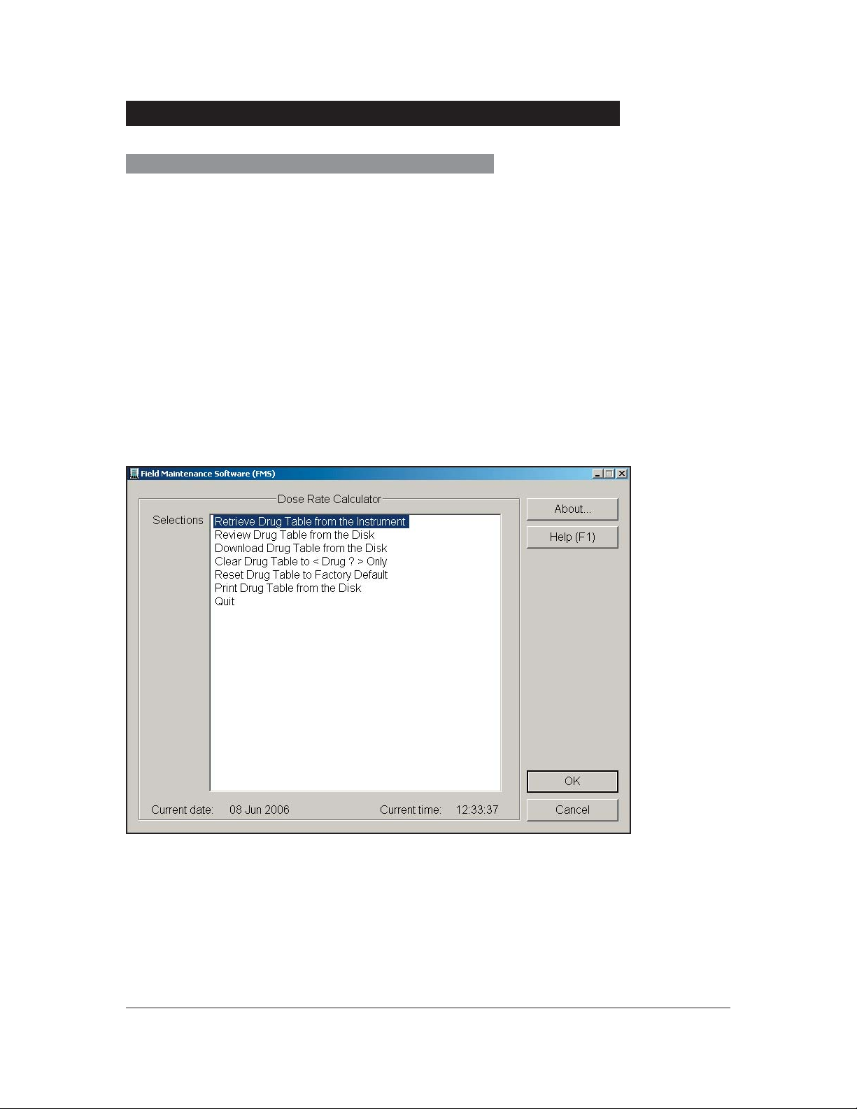
Dose Rate Calculator
This feature allows user to confi gure, review, and print Dose Rate Calculator Drug Table
fi le. User selects desired option by using keyboard arrows or by typing fi rst character,
then pressing ENTER key. See “Dose Rate Calculator Menu” fi gure below. The following
options are also included:
• Retrieve drug table from instrument.
• Review a drug table from disk in computer.
• Download a drug table from disk in computer.
• Clear drug table to (DRUG?) only.
• Reset drug table in instrument to factory default.
• Print drug table from disk in computer.
• Quit Dose Rate Calculator (and return to Instrument Programming Menu).
Dose Rate Calculator Menu
Drug table has a convention extension, .drc. drug table will contain information on Drug
Number, Drug Name, Drug Dosage, Diluent Volume, Dose Regimen, Weight, Time, Fast
Next, and Fast Previous.
36 Field Maintenance Software
Field Maintenance Software
Model 286X, v5.0
Software User Manual
Page 43

Instrument Programming (Continued)
Batch Programming
This feature allows user to manipulate instrument confi guration script fi les, and execute
a fi le to an instrument. See “Batch Programming Menu” fi gure shown below. The
following options are also included:
• Review a script fi le from disk in computer. Script fi les have convention
extension .ics.
• Execute one script fi le to an instrument (such as, change instrument to settings
specifi ed in script fi le).
• Review result of an execution of a script fi le to an instrument. Script fi les use
script fi le name plus convention extension .inf. See “Sample and Explanation of a
Batch Execution Script File” fi gure.
• Print a script fi le from disk in computer.
• Quit Batch Programming (and return to Instrument Programming Menu).
Batch Programming Menu
Field Maintenance Software
Model 286X, v5.0
Software User Manual
Field Maintenance Software 37
Page 44

Instrument Programming (Continued)
Sample and Explanation of a Batch Execution Script File
Calibration
Differences among instrument components (such as, transducers, mechanical
components, circuit gains and offsets) necessitate calibration of certain systems. These
systems detect cassette installation, latch closure, patient-side occlusions, and fl uid-side
occlusions.
Software functions are used to perform instrument calibrations. Calibration is required
after replacing certain components as a part of preventive maintenance, or if memory
contents are corrupted. Refer to Technical Service Manual for help in troubleshooting
calibration failures.
Every calibration step will display a series of numbers and a pass or fail message.
These numbers are A/D results from a calibration step. In the event of a failure the
numerical results aid in diagnosis.
38 Field Maintenance Software
Field Maintenance Software
Model 286X, v5.0
Software User Manual
Page 45

Calibration (Continued)
Calibration Options
There are six basic options from which to choose when calibrating instrument. See
“Calibration Menu” fi gure shown below.
Calibration Menu
Full Calibration - All channels
This guides user through calibration procedures for all sensor systems on all channels.
This is used most often for annual maintenance. It is suggested as a best practice to run
a full calibration whenever calibration is done to calibrate an entire system.
Single Sensor Calibration - Options:
Cassette/Latch Sensor Calibration - All channels
Patient-side Occlusion Calibration - All channels
Fluid-side Occlusion Calibration - All channels
Field Maintenance Software
Model 286X, v5.0
Software User Manual
Field Maintenance Software 39
Page 46

Calibration (Continued)
Calibration Options (Continued)
These options allow user to simultaneously calibrate individual sensor systems for all
channels. This is used most often when troubleshooting.
Single Calibration Menu - Single Channels
This guides user through steps necessary to calibrate an individual channel (such
as, cassette sensors for Channel A), as shown below. A single calibration is useful for
troubleshooting a single aspect of an individual channel.
Single Calibration Menu - Single Channels
40 Field Maintenance Software
Field Maintenance Software
Model 286X, v5.0
Software User Manual
Page 47

Calibration (Continued)
Calibration Data Menu
This menu provides user ability to retrieve calibration data from instrument and store it
to a fi le on disk.
Calibration fi le naming convention is 3 - 9 digit serial number of instrument plus:
!C for current instrument calibration log fi le (12345678.9!C);
#C for backup instrument calibration log fi le (12345678.9#C).
This menu also provides user with ability to review data fi les from disk in computer and
to print data.
Full Calibration Information
This menu provides user with ability to review full calibration conversation fi les from disk
in computer.
Calibration fi le naming convention is 3 - 9 digit serial number of instrument plus:
!F for current full calibration information fi le (12345678.9!F);
#F for backup full calibration information fi le (12345678.9#F).
This menu also provides user ability to print full calibration conversation fi les from disk in
computer.
Quit Calibration returns user to Main Menu.
Calibration Prerequisites
• Cassette/Latch Sensor Calibration with no cassettes installed must be completed
before Cassette/Latch Sensor Calibration with cassettes installed.
• 0 psi Calibration must be performed before 12 psi Calibration can be performed.
• Cassette/Latch Sensor Calibration must be performed before Fluid-side Occlusion
Calibration can be performed.
• Fluid-side Occlusion Calibration with no load must be performed before Fluid-side
Occlusion Calibration with a load can be performed.
Field Maintenance Software
Model 286X, v5.0
Software User Manual
Field Maintenance Software 41
Page 48

Calibration (Continued)
Starting Calibration
Select Calibration Menu from FMS Main Menu. Select desired calibration option. For
FMS to access calibration functions described in this section, instrument must be placed
in Maintenance Mode.
To place instrument in Maintenance Mode, turn on instrument by simultaneously
pressing ON/OFF and MORE OPTIONS keys. Instrument LCD should now read
Maintenance, followed by current device type.
NOTE: Always perform calibration procedures with instrument connected to AC power.
Instrument battery alarms are not active in Maintenance Mode.
NOTE: Ensure all channels have required equipment, as described in following
procedures. Otherwise, calibration parameters will be out of range.
Whether calibration is full or single channel, set up process of each step is the same
and the following details in full calibration for brevity.
If a failure is determined, follow prompts to repeat calibration procedures.
Every calibration step will display a series of numbers and a pass or fail message.
These numbers are A/D results from a calibration step. In the event of a failure the
numerical results aid in diagnosis.
Always perform a functional test after calibration is completed to ensure proper
operation of equipment.
Full Calibration
Full calibration performs calibration with following the criteria:
• No cassette installed and pressure zero calibration
• Cassette installed and 12-psi pressurized cassette calibration
• 12-psi pressure verifi cation
• 6-psi pressure verifi cation
• 0-psi pressure verifi cation
• Fluid-side Occlusion calibration with no load
• Fluid-side Occlusion calibration with load
42 Field Maintenance Software
Field Maintenance Software
Model 286X, v5.0
Software User Manual
Page 49

Calibration (Continued)
Cassette/Latch Sensor/OPSI Calibration
To begin Cassette/Latch Sensor Calibration, you will need one to three administration
sets that have been modifi ed for Cassette/Latch Sensor Calibration by cutting inlet
tubing from cassette, depending on whether single-channel or all-channel calibration is
to be performed.
During full calibration a cassette/latch sensor and patient side occlusion calibration,
which are both 2 step processes, are done at the same time. During the single
calibration or the single sensor calibration there will be separate 2 step calibrations.
NOTE: During Full Calibration, Cassette/Latch Sensor Calibration requires installation of
cassettes pressurized at 12 psi during step 2.
Cassette/Latch sensor calibration is performed as follows:
Step 1. Calibrate with no cassette installed.
Remove cassettes from all three channels. Ensure that optomodule sensors are clean
and free of debris. Verify pump latch is open. When prompted by FMS, press Enter
key. INSTRUMENT RESPONSE block will indicate whether a channel passed or failed
calibration. If a channel fails calibration, make sure directions given by FMS have
been followed. If a channel consistently fails, refer to Technical Service Manual for
troubleshooting procedures.
Step 2. Calibrate with a cassette installed.
When prompted by FMS, install cassettes in appropriate channels and press Enter
key. INSTRUMENT RESPONSE block will indicate which channels passed or failed
calibration. If a channel fails calibration, make sure directions given in FMS have
been followed. If a channel consistently fails, refer to Technical Service Manual for
troubleshooting procedures.
Field Maintenance Software
Model 286X, v5.0
Software User Manual
Field Maintenance Software 43
Page 50

Calibration (Continued)
Example of a Patient-side Occlusion Set
Patient-side Occlusion Calibration
Equipment required for this calibration is as follows:
• A regulated air pressure source of up to 15.00 ± 0.05 psig.
• A pressure gauge (preferably digital) that will measure 0 to 20.0 psig, ± 0.5% full
scale with a resolution of 0.1 psig.
• 1 to 3 administration sets that have been modifi ed for pressure calibration by cutting
inlet tubing fl ush with air trap. Depending on whether single-channel or all-channel
calibration is to be performed. Do not remove piston sleeve, as air will leak from set.
• Three three-way stopcocks.
An example is shown above.
NOTE: Digital pressure gauges that meet or exceed these requirements are available from
Cole-Parmer Instrument Company; 7425 North Oak Park Avenue; Chicago, IL 60648 or
other laboratory supply companies.
NOTE: A 60-ml luer-lock syringe can be used as a pressure source. Adjust plunger so that
gauge reads required pressure. Then close stopcock to syringe so that pressure is held
constant. Ensure that there are no leaks in system that could cause pressure to drop. A
regulated source from a compressor or pressurized gas tank can also be used.
NOTE: A manifold with three-way stopcocks is available from Cole-Parmer catalog #
U-06464-82.
44 Field Maintenance Software
Field Maintenance Software
Model 286X, v5.0
Software User Manual
Page 51

Calibration (Continued)
Patient-side Occlusion Calibration (Continued)
Administration Set Calibration Confi guration
AC Adapter
®
MORE
START
STANDARD
ON/OFF
OPTIONS
STOP
DISPLAY
®
BCA
PC With FMS
RS 232 Cable
Sets with inlet
tubing removed.
Pressure applied
to outlet tubing.
From pressure source.
To pressure gauge.
Confi gure apparatus as shown in fi gure “Administration Set Calibration Confi guration”.
Patient-side Occlusion Calibration is performed as follows.
Step 1. Pressure Zero Calibration
NOTE: During Full Calibration pressure zero was done during the Cassette/Latch
sensor Ǿpsi calibration.
Ensure that all cassettes are removed and all latches are open. Press Enter key to
continue test. INSTRUMENT RESPONSE block will indicate which channels passed
or failed. If a channel fails calibration, make sure that directions given by FMS have
been followed. If a channel consistently fails, refer to Technical Service Manual for
troubleshooting procedures.
Field Maintenance Software
Model 286X, v5.0
Software User Manual
Field Maintenance Software 45
Page 52

Calibration (Continued)
Patient-side Occlusion Calibration (Continued)
Step 2. 12-psi Pressurized Cassette Calibration
Ensure that pressurized cassettes are installed and that pressure is set to 12 psi +1%
(620.4 mmHg). Press Enter key to continue test. INSTRUMENT RESPONSE block will
indicate which channels passed or failed. If a channel fails calibration, make sure that
directions given by FMS have been followed. If a channel consistently fails, refer to
Technical Service Manual for troubleshooting procedures.
Step 3. 12-psi Pressure Verifi cation
Repeat Step 2.
Step 4. 6-psi Pressure Verifi cation
Ensure that pressurized cassettes are installed and pressure is set to 6 psi +1% (310.2
mmHg). Press Enter key to continue test. INSTRUMENT RESPONSE block will indicate
which channels passed or failed. If a channel fails calibration, make sure that directions
given by FMS have been followed. If a channel consistently fails, refer to Technical
Service Manual for troubleshooting procedures.
Step 5. 0-psi Pressure Verifi cation
Ensure that pressurized cassettes are installed and that pressure is set to 0 psi.
Press Enter key to continue test. INSTRUMENT RESPONSE block will indicate which
channels passed or failed. If a channel fails calibration, make sure that directions given
by FMS have been followed. If a channel consistently fails, refer to Technical Service
Manual for troubleshooting procedures.
Fluid-side Occlusion Calibration
Equipment required for Fluid-side Occlusion calibration is as follows.
• Fluid-side Occlusion calibration fi xture.
• One to three cassettes depending on whether single-channel or all-channel
calibration is to be performed which have been modifi ed for Fluid-side Occlusion
calibration.
Cassette modifi cation consists of removal of piston sleeves from piston area. DO NOT
REMOVE PISTON. Remove elastomeric valve area in cassette, using a pointed X-acto
knife. Administration sets can be made easier to handle by shortening inlet and outlet
tubing. A set of 3 pre modifi ed cassettes can be ordered as part #148169-100. A set of
them come with calibrations device part #2861461. See fi gure 1 and fi gure 2.
46 Field Maintenance Software
Field Maintenance Software
Model 286X, v5.0
Software User Manual
Page 53

Calibration (Continued)
Fluid-side Occlusion Calibration (Continued)
Figure 1 Figure 2
NOTE: When performing a Fluid-side Occlusion calibration procedure, be sure to use
cassettes that have been modifi ed for Fluid-side Occlusion. Use of cassettes with piston
sleeves during Fluid-side Occlusion calibration can result in erratic performance.
This calibration procedure is performed as follows.
Step 1. Fluid-side Occlusion Calibration with No Load
Insert Fluid-side Occlusion calibration cassettes. Place instrument into a 90° upright
position. Press Enter key to continue test. INSTRUMENT RESPONSE block will indicate
which channels passed or failed. Motors will run for approximately two minutes. If a
channel fails calibration, make sure that directions given in FMS have been followed.
If a channel consistently fails, refer to Technical Service Manual for troubleshooting
procedures.
Step 2. Fluid-side Occlusion Calibration with Load
NOTE:
calibration fixture and verify that weights in fixture move freely. If fixture has been dropped,
replacement may be necessary. See Service Bulletin 497 for the procedure to check for
proper function.
Before performing Step 2, look through three slots on face of Fluid-side Occlusion
Turn instrument upside down and position it vertically. Remove lower housing. Place
Fluid-side Occlusion calibration fi xture on instrument in place of lower housing. Ensure
that weight shafts are aligned with pump latches. Press Enter key to continue test.
Motors will run for approximately 2 minutes. If a channel fails calibration, make sure
that directions given by FMS have been followed. If a channel consistantly fails, refer to
Technical Service Manual for troubleshooting procedures.
Field Maintenance Software
Model 286X, v5.0
Software User Manual
Field Maintenance Software 47
Page 54

Calibration (Continued)
Calibration Data Menu
Calibration Data Menu option provides commands for retrieving from instrument, storing,
displaying, or printing of calibration data. Calibration data displays operator’s comments,
instrument serial number, software version, date and time, and retrieved calibration data.
Data will refl ect whether all sensors for each channel completed required calibration.
See fi gure “Calibration Data Menu”.
To access these commands, instrument must be placed in Maintenance Mode by
simultaneously pressing ON/OFF and MORE OPTIONS keys. Next, Calibration Menu
is selected from Main Menu. Then, Calibration Data Menu is selected from Calibration
Menu.
Calibration Data Menu
48 Field Maintenance Software
Field Maintenance Software
Model 286X, v5.0
Software User Manual
Page 55

Calibration (Continued)
Calibration Data Menu (Continued)
Following are Calibration Data Menu options:
1. Retrieve Calibration Data from Instrument
If retrieved calibration data is stored on disk, the following information is requested.
Operator Comment (optional) - This information can be the name of person storing
calibration data from instrument or any other information, up to a maximum of 20
characters, including spaces. Information will be stored on disk along with calibration
data and will also appear on printouts. Retrieved fi le names are created using serial
number, as shown in following example.
S/N 123456789 creates fi le: 12345678.9!C
2 trailing characters (!C) are used by FMS to identify fi les as retrieved calibration data. If
a retrieved calibration data fi le for a particular instrument already exists, FMS will prompt
user to make a decision on whether to rename existing fi le and store it as a new fi le, append new data to existing fi le, or delete existing fi le and create a new one.
If a fi le is renamed, 2 trailing fi lename characters to identify fi le will be #C.
2. Review Calibration Data from Disk
This is used to display calibration data that has been stored in a selected computer fi le.
See “Retrieved Calibration Data Report” fi gure.
3. Print Calibration Data from Disk
This is used to print calibration data that has been stored in a selected computer fi le.
4. Quit
This is used to exit Calibration Data Menu and return to Calibration Menu.
NOTE: Calibration fi les for more than one instrument may exist on current disk. When
displaying or printing data from a fi le, user must enter desired instrument serial number or
press space bar to provide a directory of Calibration Data fi les that are available on current
disk. Up or down arrow keys can then be used to highlight desired serial number. Press
Enter key to retrieve desired Calibration Data fi le name. Press Enter key to retrieve fi le for
displaying or printing.
Field Maintenance Software
Model 286X, v5.0
Software User Manual
Field Maintenance Software 49
Page 56

Calibration (Continued)
Calibration Data Menu (Continued)
Retrieved Calibration Data Report
Full Calibration Information Menu
Full Calibration Information Menu allows user to review (display) and print calibration
information obtained during a Full Calibration and stored to a fi le. See fi gure “Full
Calibration Information Menu”.
Full Calibration Information Menu option provides user the following commands:
• Review Full Calibration Information
• Print Full Calibration Information
50 Field Maintenance Software
Field Maintenance Software
Model 286X, v5.0
Software User Manual
Page 57

Calibration (Continued)
Full Calibration Information Menu (Continued)
Full Calibration Information Menu.
Full Calibration fi le names are created using serial number, plus extension !F as shown
in following example. See “Full Calibration Report” fi gure.
S/N 123456789 creates fi le: 12345678.9!F
If a Full Calibration data fi le for a particular instrument already exists, FMS will prompt
user to make a decision on whether to rename existing fi le and store it as a new fi le,
append new data to existing fi le, or delete existing fi le and create a new one.
Filename for a backup Full Calibration fi le includes serial number of instrument plus
extension #F. If a fi le is renamed, 2 trailing characters to identify fi le will be #F.
Field Maintenance Software
Model 286X, v5.0
Software User Manual
Field Maintenance Software 51
Page 58

Full Calibration Report
Calibration (Continued)
Exiting Calibration Menu
To exit Calibration Menu and return to Main Menu, select Quit Calibration Menu
command and press Enter key.
52 Field Maintenance Software
Field Maintenance Software
Model 286X, v5.0
Software User Manual
Page 59

Logs Menu
Instrument keeps a record of occurrences (such as, Watchdog alarms, changes in
device type, and faults) in a log. Logs Menu allows user to access this information, and
to save it in a fi le to any specifi ed drive and directory path.
Logs Menu includes following options:
• Event Log
• Alarm Log
• Status Log
• All Logs
• Quit Logs Menu
In each option selected (except Quit Logs Menu), option menu allows user to specify a
drive and directory path for each of following menu choices:
Retrieve Log from instrument.
NOTE: If log already exists on disk, FMS provides an option to rename, delete, or append
old log fi le. Log will be retrieved from instrument and displayed on monitor screen. When
retrieval is complete, user can scroll throughout log.
Review Log from Disk.
Print Log from Disk.
Field Maintenance Software
Model 286X, v5.0
Software User Manual
Field Maintenance Software 53
Page 60
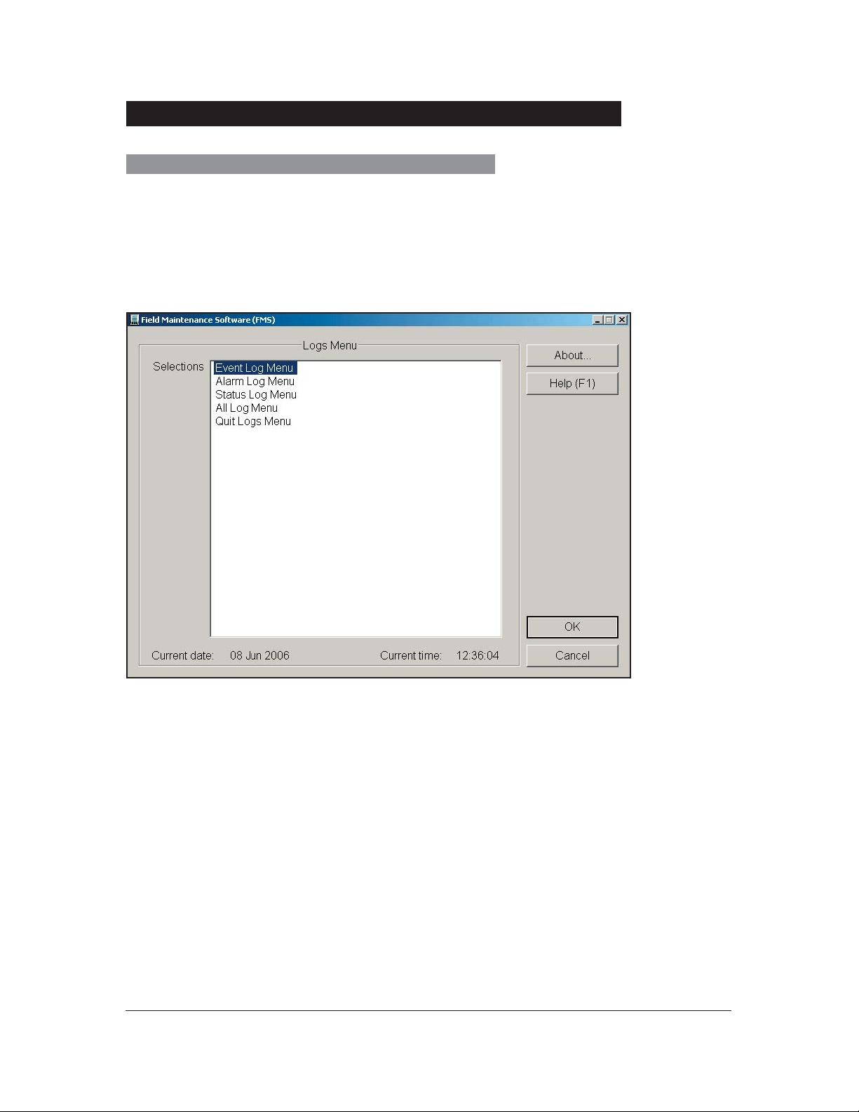
Logs Menu (Continued)
Storing a Log to File
Event, Status, Alarm, and All Log menus can be retrieved from instrument and stored
to a fi le, displayed, and/or printed. From Main Menu, select Logs Menu. Logs Menu will
then be displayed. See fi gure “Logs Menu”.
Logs Menu
54 Field Maintenance Software
Field Maintenance Software
Model 286X, v5.0
Software User Manual
Page 61

Logs Menu (Continued)
Storing a Log to File (Continued)
To retrieve a log, put instrument in Maintenance Mode by simultaneously
Pressing ON/OFF and MORE OPTIONS keys. Information that will be requested is as
follows:
Operator Comment (optional): This information can be name of person retrieving log
from Instrument or any other information, up to a maximum of 20 characters, including
spaces. Information will be stored on disk along with retrieved information and will also
appear on printouts.
File names are created using 3 - 9 digit serial number of instrument, as shown in “Log
File Naming Conventions” fi gure.
To retrieve a log, put instrument in Maintenance Mode by simultaneously pressing ON/
OFF and MORE OPTIONS keys. The following information will be requested:
Operator Comment (optional): This information can be name of person retrieving log
from instrument or any other information, up to a maximum of 20 characters, including
spaces. Information will be stored on disk along with retrieved information and will also
appear on printouts.
File names are created using 3 - 9 digit serial number of instrument, as shown in
following example.
S/N 123456789 creates fi le: 12345678.9_ _
There are 2 trailing underline characters that are used by FMS to identify fi les as Event
Logs, Alarm Logs, Status Logs, or All Logs. Upon entry of previous information, FMS will
retrieve log, decode information, and store it on disk. If a log for an instrument with same
serial number exists, FMS will prompt user to make a decision on whether to rename
existing fi le and store it as a new fi le, append new data to existing fi le, or delete existing
fi le and create a new one.
Log File Naming Conventions
Event Log:
12345678.9!E-Current Event Log fi le (Formatted)
12345678.9#E-Backup Event Log fi le (Formatted)
12345678.9!X-Current Event Log fi le (Raw)
12345678.9#X-Backup Event Log fi le (Raw)
Field Maintenance Software
Model 286X, v5.0
Software User Manual
Field Maintenance Software 55
Page 62

Logs Menu (Continued)
Storing a Log to File (Continued)
Alarm Log:
12345678.9!A-Current Alarm Log fi le (Formatted)
12345678.9#A-Backup Alarm Log fi le (Formatted)
12345678.9!Y-Current Alarm Log fi le (Raw)
12345678.9#Y-Backup Alarm Log fi le (Raw)
Status Log:
12345678.9!S-Current Status Log fi le (Formatted)
12345678.9#S-Backup Status Log fi le (Formatted)
12345678.9!Z-Current Status Log fi le (Raw)
12345678.9#Z-Backup Status Log fi le (Raw)
All Log:
12345678.9!T-Current All Log fi le (Formatted)
12345678.9#T-Backup All Log fi le (Formatted)
12345678.9!W-Current All Log fi le (Raw)
12345678.9#W-Backup All Log fi le (Raw)
NOTE: When storing a Log to a fi le, if disk becomes full, user will be advised.
56 Field Maintenance Software
Field Maintenance Software
Model 286X, v5.0
Software User Manual
Page 63

Logs Menu (Continued)
Displaying a Log
User can view an Event, Alarm, Status, or All Log directly from instrument or from a disk
fi le. Viewing a log from an instrument can be done using Retrieve Log from Instrument
option. A log that has been fi led on a disk can be viewed using Review Log from Disk
option.
Because logs for more than 1 instrument may exist on a current disk, user must select
serial number for desired log on current disk. Up or down arrow keys can be used to
highlight desired log fi le name. Press Enter key to retrieve highlighted fi le for viewing on
screen.
Figure below gives an example of an Event Log Report. Event Log report shows
Operator Comment, instrument Serial Number, Date Stored, and Time Stored.
EVENT LOG REPORT
Operator Comment: John Doe
Instrument Serial Number: 123456789
Instrument Software version #: 5.0
FMS version # 5.0
Date Stored: 9-14-2006
Time Stored: 13:29:53
E#1 08:48:31a01Jun 945311Device Type change
E#2 08:49:05a01Jun94275BCannot home motor
E#3 08:49:36a01Jun9453332Requested Data Init
E#4 08:49:57a01Jun945331Requested Data Init
Events are displayed in chronological order. Each event will show time and date that
event occurred, Event Code, affected channels, and a description of Event Code.
NOTE: When viewing Event Log Report, channel indicators are defi ned as follows: A, B, or C
represent individual pump channels and I represents instrument or system fault. A numerical
value in channel column is for factory use.
Field Maintenance Software
Model 286X, v5.0
Software User Manual
Field Maintenance Software 57
Page 64

Logs Menu (Continued)
Printing a Log
User can print an Event, Alarm, or Status Log that has been stored on a disk. A log that
has been fi led on a disk can be printed using Print Log From Disk option.
Because more than 1 log of any type may exist on current disk, user must select from
desired log on current disk. Up or down arrow keys can be used to highlight desired log
fi le name. Pressing Enter key prints highlighted fi le.
Exiting Logs Menu
To exit Logs Menu and return to Main Menu, select Quit Logs Menu command and
press Enter key, or press ESC key. All logs saved to disk will still be available for review
or printing during next FMS session.
Exiting FMS
Turn off instrument when exiting FMS. To exit select Quit Program command from Main
Menu and pressing Enter key returns user to Windows.
58 Field Maintenance Software
Field Maintenance Software
Model 286X, v5.0
Software User Manual
Page 65

Appendix
Parameter Verification Procedures
After Instrument Configuration and Maintenance mode changes, certain parameters
should be verified by exercising one of following procedures.
NOTE: On the confi guration pages line items changed from factory defaults will be prefi xed
with an asterisk.
Verification Procedure A - Device Settings
1. Turn instrument on by pressing ON/OFF key.
2. Press MORE OPTIONS key to activate DEVICE softkey.
3. Press DEVICE softkey to display “Change Device Type” page.
4. If desired Device Type is not highlighted, press SELECT softkey as needed
to highlight desired Device Type, then press ENTER softkey.
5. Press STANDARD DISPLAY key to return to Standard Display.
6. Press MORE OPTIONS key to activate CONFIG softkey.
7. Press CONFIG softkey to display “Instrument Settings” page.
8. If needed, press NEXT PAGE softkey to display parameter values page
showing desired value.
9. Visually confi rm desired value.
10. Press STANDARD DISPLAY key to return to Standard Display, or press
ON/OFF key to turn off instrument.
Verification Procedure B - Current Settings
1. Turn on instrument by pressing ON/OFF key.
2. Press MORE OPTIONS key to activate CONFIG softkey.
3. Press CONFIG softkey to display Instrument Settings page.
4. If necessary, press NEXT PAGE softkey to display parameter showing
desired value.
Field Maintenance Software
Model 286X, v5.0
Software User Manual
Appendix 59
Page 66

Parameter Verification Procedures (Continued)
Verification Procedure B - Current Settings
(Continued)
5. Visually confi rm desired value.
6. Press STANDARD DISPLAY key to return to Standard Display, or press
ON/OFF key to turn off instrument.
Verification Procedure C -Enable DRC
1. Turn on instrument by pressing ON/OFF key.
2. Press A, B, C key as needed to activate channel information page.
3. Press MORE OPTIONS key to activate CalcOn softkey.
4. Press CalcOn softkey to activate Dose Rate Calculator Page.
5. Select a drug that is not DRUG? and press ENTER.
6. Verify that Concentration Unit and Dose Rate Unit can/cannot be changed.
7. Press STANDARD DISPLAY key to return to Standard Display, or press
ON/OFF key to turn off instrument.
Verification Procedure D - BATLOG
1. Turn on instrument by pressing ON/OFF key.
2. Press MORE OPTIONS key twice to activate BATLOG softkey.
3. Press BATLOG softkey to display Biomed Battery History page.
4. Visually confi rm desired value.
5. Press STANDARD DISPLAY key to return to Standard Display, or press
ON/OFF key to turn off instrument.
60 Appendix
Field Maintenance Software
Model 286X, v5.0
Software User Manual
Page 67

Service Information
If difficulties are encountered while using FMS software, consult the following sources of
information before contacting Cardinal Health, Technical Support:
•
README files or package inserts accompanying product.
• Appropriate hardware manuals (instrument DFU and Service Manual, and related
Service Bulletins), if a hardware problem is suspected.
Technical Support
If software fails to respond and cause cannot be determined, contact a Cardinal Health
representative. Reference “General Contact Information” at the front of this document.
Provide following information:
• description of difficulty experienced
• message displayed at time of difficulty
• software version
Software Return
Contact Cardinal Health to obtain a return authorization number prior to shipment.
Reference “General Contact Information” for “Customer Care” at the front of this
document.
Package software (preferably in original packaging), reference return authorization
number, and return to closest facility.
Trademarks
Alaris® and MedSystem III® are registered trademarks of Cardinal Health, Inc. or one of
its subsidiaries. All other trademarks are the property of their respective owners.
Field Maintenance Software
Model 286X, v5.0
Software User Manual
Appendix 61
Page 68

THIS PAGE
INTENTIONALLY
LEFT BLANK
62 Appendix
Field Maintenance Software
Model 286X, v5.0
Software User Manual
Page 69

Part Number 10014647 ©1994 - 2006 Cardinal Health, Inc. or one of its subsidiaries. All rights reserved.
Field Maintenance Software
Model 286X, v5.0
Software User Manual
 Loading...