

Page 1
..
MedSystem
III™
For
most
Troubleshooting
common
errors.
Tip
Sheet
Error
Codes
(6,3):
(16,X):
fere
SO
人
(31,3):
1.
Check
disconnected.
2.
Use a known
to
Air-in-line
Air-in-line
1.
Clean
2.
Replace
1.
Reseat
2.
Check
3.
Check
4.
Replace
5.
Replace
Opto
Top
Fuse.
Battery.
Troubleshooting
see
if
any
Air-in-Line
good
Air-in-Line
sensors
sensors*.
Module
Opto
are
defective.
and
Module*.
Board.
Power
MEA*.
Supply*.
do
CID/LIP
Steps
Sensors
Sensor
Replace
have
become
to
find
out
which
defective
calibration.
Xz
(33,3)
(40,X):
(95,X):
Chana
O-A
3
る
(259):
(263):
A
1.
Reseat
2.
Replace
1.
Reseat
2.
Replace
1.
Check
Top
Top
to
disconnected.
2,
Replace
causes
1.
Clean
2.
Switch
with
the
channel
drive
Drive
channel
4.
Do
Pressure
Giso
Check
Board
MEA*.
Board.
Power
see
the
Supply",
if
any
Air-in-Line
pump
and
module
Module
replace
MEA*.
calibration.
Lihumim
and
EPOM.
Air-in-Line
Sensor*
to
go
into
do
FSOD
with
another
replace
Drive
bet
Sensors
on
whichever
alarm
when
calibration.
channel.
Module”.
have
become
channel
started.
if
error
If
error
moves
stays
with
in
same
Page 2
(272):
1.
Do
CID/LIP
calibration.
(278):
(276);
(289)/(290)
(292)
uN
1.
2.
1.
1.
2.
1.
(293)
ON
Clean
Switch
with
channel
Do
FSOD
Clean
Do
FSOD
Switch
with
channel
Reset
1.
Reset
and
drive
Drive
replace
Encoder
drive
Drive
replace
faults.
faults.
.
Lubricate
module
Module
channel,
with
replace
MEA*.
calibration.
Disk.
Make
calibration.
module
Module
with
replace
MEA*.
do
another
Drive
sure
another
Drive
FSOD
channel.
calibration.
Module.
dust
cover
channel.
Module”.
0000
If
error
If
error
is
properly
If
error
If
error
moves
stays
in
installed.
moves
stays
with
in
same
with
same
(301)/(24)
(302)/(47)
1.
.
>
.
.
.
BOND
(305)/(88)
(303)/(67)
1.
2.
一
(311)
Replace
Reseat
Check
Check
Replace
Replace
Replace
.
Reseat
.
Check
.
Check
.
Replace
AWN
.
Reseat
.
Check
.
Check
.
Replace
BONS
MEA*.
Top
Board.
Fuse.
Battery.
Power
Power
MEA*.
Top
Board.
Fuse.
Battery.
MEA*.
Top
Board.
Fuse.
Battery.
Power
Supply
Supply
Supply
Board”,
Board".
Board".
Page 3
(313)
1.
Replace
Air-in-Line
Sensor
*.
(314)
(315)
(326)
sofico
5,0
*
Follow
MK
1.
1.
2.
level
Replace
Replace
1.
Do
FSOD.
Replace
of
testing
Air-in-Line
Air-in-Line
MEA*.
Guide
Sensor*.
Sensor”.
Lines
in
Service
Bulletin
404A.
Page 4
il
¡IVAC
#TO*CAL
\
SYSTEMS
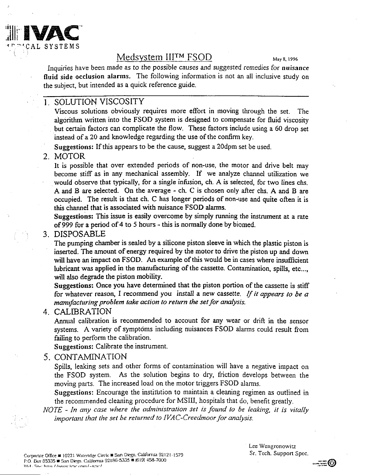
Inquiries
fluid
the
1.
.
.
have
been
made
side
occlusion
subject,
but
SOLUTION
Viscous
algorithm
but
instead
solutions
written
certain
factors
of a 20
Suggestions:
alarms.
intended
VISCOSITY
obviously
into
can
and
knowledge
If
this
MOTOR
It is
possible
become
would
A
occupied.
this
observe
and B are
channel
Suggestions:
of
999
for a period
that
stiff
as
selected.
The
that
This
over
in
any
that
result
is
associated
issue
of 4 to 5 hours - this
DISPOSABLE
The
pumping
inserted.
will
have
lubricant
will
also
Suggestions:
for
whatever
manufacturing
CALIBRATION
Annual
systems. A variety
failing
to
Suggestions:
chamber
The
amount
an
impact
was
applied
degrade
the
Once
reason, I recommend
problem
calibration
perform
the
Calibrate
Medsystem
as
to
the
The
quick
a
as
requires
the
FSOD
complicate
regarding
appears
to
be
extended
mechanical
typically,
is
for a single
On
the
that
ch.
average - ch. C is
with
is
easily
is
sealed
of
energy
on
FSOD.
in
the
piston
you
have
take
is
recommended
of
symptoms
An
manufacturing
mobility.
determined
action
calibration.
the
instrument.
UM
possible
following
reference
system
the
flow.
the
cause,
periods
assembly.
C has
nuisance
overcome
by a silicone
required
example
FSOD
causes
information
guide.
more
effort
is
designed
These
the
use
suggest a 20dpm
of
infusion,
longer
FSOD
by
is
normally
piston
by
the
of
of
the
that
you
install a new
to
return
to
including
the set
account
nuisances
and
suggested
is
in
moving
to
factors
of
the
confirm
non-use,
If
we
ch. A is
chosen
periods
simply
motor
this
the
of
alarms.
running
done
sleeve
to
would
cassette.
piston
cassette,
for
for
any
FSOD
remedies
not
an
all
inclusive
through
compensate
include
set
the
motor
analyze
selected,
only
non-use
by
biomed.
in
which
drive
be
in
for
using a 60
key.
be
used.
and
channel
for
after
chs. A and B are
and
the
instrument
the
the
piston
cases
where
Contamination,
portion
of
//
the
it
analysis.
wear
or
drift
alarms
could
May
8,
for
nuisance
study
the
set.
fluid
viscosity
drop
drive
belt
utilization
two
lines
quite
often
at a rate
plastic
piston
up
and
insufficient
spills,
cassette
appears
in
to
the
result
1996
on
The
set
may
we
chs.
it
is
is
down
etc...,
is
stiff
be
a
sensor
from
NOTE - In
Box
Gites
Office
85335
hit
Corporate
Р.О.
Web.
CONTAMINATION
Spills,
the
moving
Suggestions:
the
important
danny
leaking
FSOD
parts.
recommended
any
Wateridge
10221
a
Diego.
San
ae
com
system.
Encourage
case
that
California
nef
sets
and
The
increased
cleaning
where
the
set
San
a
Circle
92186-5335
other
As
the
the
procedure
the
be
returned
Diego.
(619)
m
forms
solution
load
institution
of
contamination
begins
on
the
motor
to
for
MSIL,
administration
to
IVAC-Creedmoor
California
92124-1579
458-7000
will
have a negative
to
dry,
friction
triggers
FSOD
maintain a cleaning
hospitals
set
is
found
for
develops
alarms.
regimen
that
do,
to
be
analysis.
between
as
benefit
leaking,
Lee
Sr.
greatly.
it
Wengronowitz
Support
Tech.
impact
outlined
is
on
the
in
vitally
Spec.
om
ire
©
Page 5
ALARIS
MEDICAL
MEMO
Date
11-19-98
To:
Technical
Cc:
Rob
SYSTEMS
Support
Pecsar,
Tam
Tran
From:
Subject:
1.
At
password.
can
The
file.
installed
2.
Hiep
Background
the
first
not
be
only
The dle.pwi
(default
Resetting
Exit
DLE
Launch
Open
Click
Click
Click
Record
Click on
.
Uncheck
OBNOASWH>
410.
Click
11.
Click
12.
On
the
13.
Hit
the
14.
Click
15.
Verify
16.
Click
Dinh
Resetting
time
of
running
This
password
changed.
way
to
change
file
at
cAmsiiidle)
program.
Windows
‘Msiiidle’
or
‘View’.
‘Options’.
‘View’
‘Apply’
‘OK’
‘Yes’
tab.
the
settings
‘Show
‘Hide
button.
button.
right
hand
‘Delete’
button
that
there
ail
file
key
‘View’.
the
DLE
(Version
DLE,
will
be
the
DLE
is
located
Password
NT
Explorer
‘msiiidie’
on
files’
extensions
side
on
on
is
no
folder,
this
button.
window,
the
keyboard.
the
‘Confirm
dle.pw
the
program
saved
password
in
the
directory
(Start,
or
window.
for
known
click
File
file
in
2.00)
Password
asks
in
the
is
for
Program,
the
folder
file
the
dle.pwl
Delete’
the
right
the
users
hidden
to
where
reset
the
file,
it
Windows
Windows
where
types’
hand
box.
icon
popup
side
Instruction
to
set
named
by
deleting
DLE
DLE
to
highlight
die.pwi,
application
NT
Explorer).
was
window.
window.
the
DLE
and
the
dle.pwl
was
NT
installed.
it.
Memo:
Resetting
the
DLE
(Version
2.00)
Password
Instruction
Page 1 of
3
Page 6
ALARIS
MEDICAL
SYSTEMS
17.Click
18.
Click
19.
Reset
20.
Click
21.Click
22.
Close
23.
Start
3.
Resetting
+
Exit
DLE
Launch
Open
Click
AN
Click
Glick
Record
Uncheck
OND
Folders.
9.
Click
10.
Click
11.
Click
12.
On
the
413.
Hit
the
14.
Click
15.
Verify
16.
Click
17.
Click
18.
Click
24.
Reset
19.
Click
20.
Click
21.Close
22.
Start
‘Options’.
‘View’
‘Apply’
‘OK’
the
the
settings
button.
the
‘Windows
DLE
tab.
button.
program.
program.
'Windows
‘Msilidle’
‘View’.
‘Folder
‘View’
on
‘Apply’
‘OK’
Options...’
tab.
the
settings
‘Hide
‘Show
button.
button.
right
hand
‘Delete’
‘Yes’
button
that
there
‘View’.
‘Folder
‘View’
the
‘Apply’
‘OK’
the
the
Options...’.
tab.
settings
button.
button.
‘Windows
DLE
on
this
NT
Password
Explorer’
or
‘msilidie’
on
this
file
extensions
all
files’
side
window,
key
on
the
on
the
is
no
dle.pwi
on
this
Explorer’
program.
window
Explorer’
Enter
and
(Start,
folder,
window.
for
button
under
click
keyboard.
‘Confirm
file
window
window.
Enter and
as
recorded
window.
confirm a new
for
Program,
or
the
known
Hidden
the
File
Delete’
in
the
as
recorded
confirm a new
Windows
folder
file
types’
files.
dle.pwi
right
hand
earlier.
password.
Windows
Explorer).
where DLE
box
icon
popup
side
earlier.
password.
was
under
to
highlight
window.
window.
95
installed.
Files
and
it.
4.
Exit
Launch
Open
Click
DONT
Memo:
Resetting
DLE
program.
‘File
Manager’.
‘msilidle’
‘View’.
Resetting
the
folder,
DLE
(Version
Password
or
the
folder
2.00)
where
Password
for
Instruction
Windows
DLE
was
installed.
3.1X
Page 2 of
3
Page 7
ALARIS
の
Click
Record
Check
の
Click
On
oo
10.
Hit
the
11.
Click
12.
Click
13.
Verify
14,
Click
15.
Click
16.
Reset
17.
Click
18.
Close
19.
Start
[end]
MEDICAL
‘By
File
the
‘Show
‘OK’
the
right
‘Delete’
‘OK’
‘Yes’
that
View.
'By
the
‘OK
the
the
SYSTEMS
Type...’.
settings
Hidden/System
button.
hand
side
key
button
button
there
File
settings
on
on
is
no
Type...”.
on
button.
‘File
Manager’
DLE
program.
on
this
window,
on
the
the
the
die.pwl
this
window.
Files’.
click
keyboard.
‘Delete’
popup
‘Confirm
file
window
window.
Enter
and
the
die.pwt
window.
File
Delete’
in
the
right
as
recorded
confirm a new
icon
papup
hand
earlier.
password.
ta
window.
side
window.
highlight
it.
Memo:
Resetting
the
DLE
(Version
2.00)
Password
Instruction
Page 3 of
3
Page 8
Ни.
al
IVAC
MEDICAL
SYSTEMS
NOTIFICATION
‘
OF
PRACTICES
TO
REDUCE
THE
OCCURRENCE
THE
Attention:
IVAC
alarms
e
9
s
Medical
can
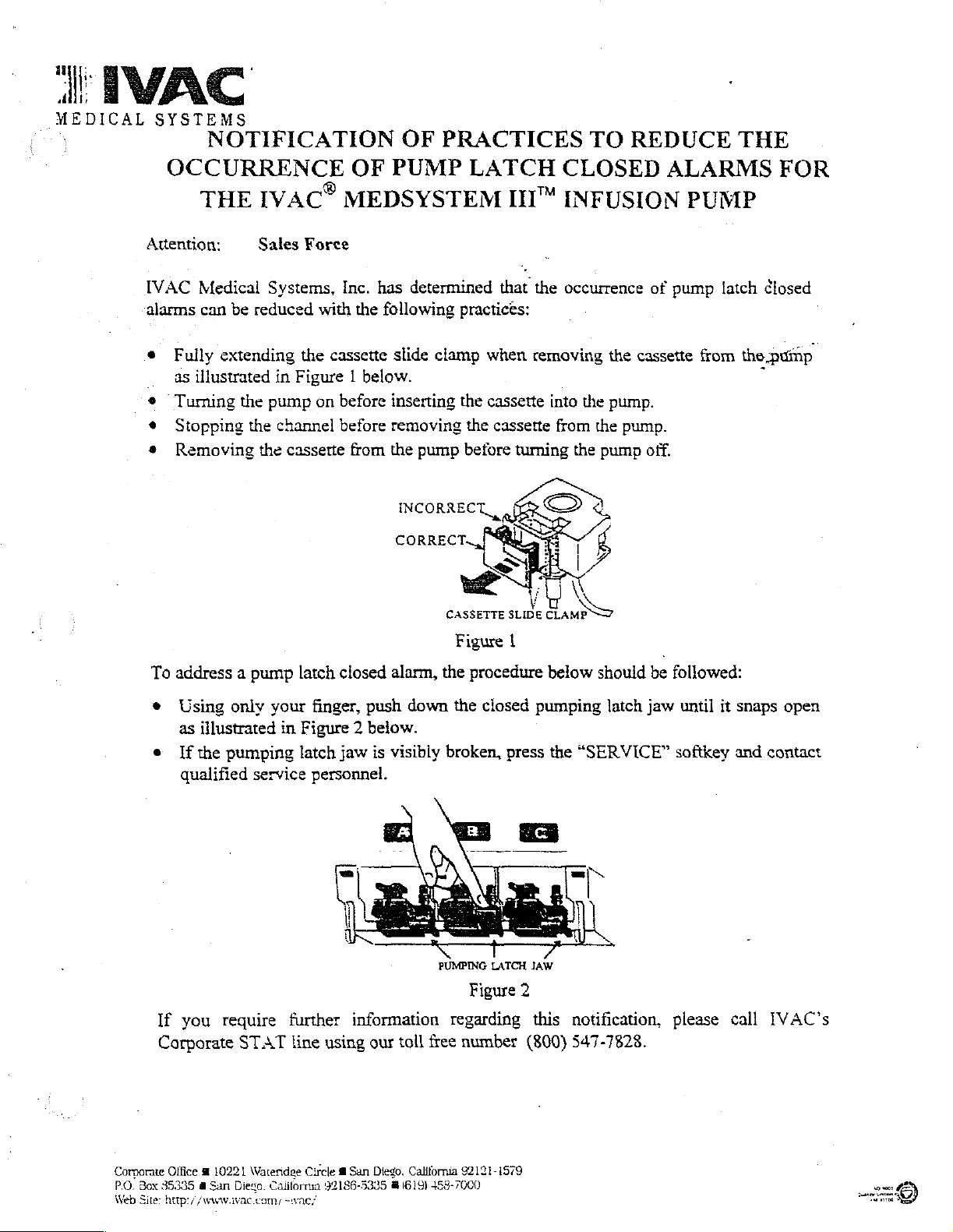
Fully
extending
as
illustrated
Turing
Stopping
Removing
IVAC®
Sales
be
reduced
the
the
the
OF
MEDSYSTEM
Force
Systems,
in
Figure 1 below.
pump
channel
cassette
with
the
cassette
on
Inc.
the
before
before
from
PUMP
has
determined
following
slide
clamp
inserting
removing
the
pump
INCORRECT
LATCH
III™
that
practices:
when
the
cassette
the
cassette
before
CASSETTE
SLIDE
CLOSED
INFUSION
the
occurrence
removing
into
from
turning
the
<>
Em
the
the
pump
of
the
cassette
pump.
pump.
off.
ALARMS
PUMP
pump
latch
from
the
FOR
closed
pump
7
To
address a pump
+
Using
as
illustrated
e
{f
the
pumping
qualified
If
you
require
Corporate
only
service
STAT
latch
closed
your
finger,
in
Figure 2 below.
latch
jaw
personnel.
further
line
information
using
alarm,
push
is
visibly
our
down
toll
free
Figure
the
procedure
the
closed
broken,
PUMPING
press
LATCH
Figure
regarding
number
1
pumping
JAW
2
this
(800)
below
the
should
latch
“SERVICE”
notification,
547-7828.
be
followed:
jaw
until
softkey
please
it
snaps
and
call
open
contact
IVAC's
Corporate
PO. Box
35335
Web
Site:
Office @ 10221
dl
San
http:/
/www.ivac.com/
Wateridge
Di
Circle 8 San
California
92186-5335 @ 1819)
-wac/
Diego.
California
92121-1579
453-7000
Page 9
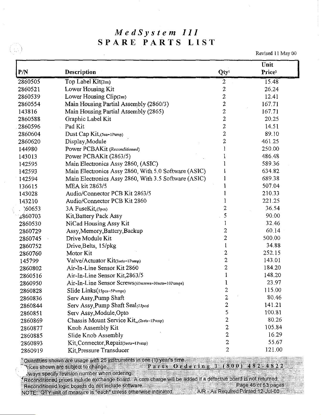
MedSystem
III
P/N
2860505
2860521
2860539
2860554
143816
2860588
2860596
2860604
2860620
144980
143013
142595
142593
142594
136615
143028
143210
.
160653
2860703
2860530
2860729
2860745
2860752
2860760
145799
2860802
2860516
2860950
2860828
2860836
2860844
2860851
2860869
2860877
2860885
2860893
2860919
Description
Top
Lower
Lower
Main
Main
Graphic
Pad
Dust
Display,
Power
Power
Main
Main
Main
MEA
Audio/Connector
Audio/Connector
3A
Kit,Battery
NiCad
‘Assy,Memory,
-
Drive
Kit,
SPARE PARTS
Label
Kit
FuseKit,(5pcs)
Drive
Motor
Valve/Actuator
Air-In-Line
Air-In-Line
Air-In-Line
Slide
Serv
Serv
Serv
Chassis
Knob
Slide
Kit,Pressure
Kit(2ea)
Housing
Housing
Housing
Housing
Label
Cap
Kitf,(5ea=1Pump)
Module
PCBAKit
PCBAKit
Electronics
Electronics
Electronics
kit
2863/5
Pack
Housing
Module
Belts,
15/pkg
Kit
Sensor
Sensor
Sensor
Links(15pes=5Pumps)
Pump
Assy,
Pump
Assy,
Assy,Module,Opto
Mount
Assembly
Assembly
Knob
Connector,
Transducer
Kit
Clip(2es)
Partial
Partial
Kit
Assembly
Assembly
(2860/3)
(2865)
|
(Reconditioned)
(2863/5)
Assy
Assy
Assy
PCB
PCB
2860,
2860,
Kit
Kit
2860,
2863/5
2860
(ASIC)
With
5.0
With
3.5
Software
Software
Assy
Assy
Kit
Battery,
Backup
Kit
Kit@sets=1Pump)
Kit
2860
Kit,2863/5
Screws(soscrews=30sets=10Pumps)
Shaft
Seal(15pes)
Shaft
(2sets-1Pump)
Service
Kit,
Kit
RepairGsets=1Pump)
LIST
(ASIC)
(ASIC)
Qty!
2
2
2
2
2
2
2
2
2
1
1
1
1
1
1
1
1
2
„5
1
2
2
1
2
2
2
1
1
2
2
2
5
2
2
2
2
2
Revised
Unit
Price
15.48
26.24
12.41
167.71
167.71
20.25
14.51
89.10
46125
250.00
486.48
589.36
634.82
689.38
507.04
210.33
221.25
36.54
90.00
32.46
60.14
500.00
34.88
252.15
143.01
184.20
148.20
23.97
115.00
80.46
141.21
100.81
80.26
105.84
16.29
55.67
121.00
11
May
00
Page 10
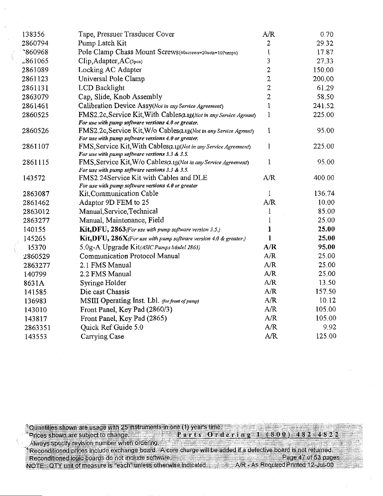
138356
2860794
"860968
2861065
2861089
2861123
2861131
2863079
2861461
2860525
2860526
2861107
2861115
143572
2863087
2861462
2863012
2863277
140155
145265
15370
2860529
2863277
140799
8631A
141585
136983
143010
143817
2863351
143553
Tape,
Pressuer
Pump
Pole
Clip,
Locking
Universal
LCD
Cap,
Calibration
FMS2.2c,
For
Latch
Clamp
Adapter,
AC
Pole
Backlight
Slide,
Service
use
with
pump
Kit
Chass
AC
Adapter
Knob
Device
FMS2.2c,Service
For
use
with
pump
FMS,
For
FMS,
For
Service
use
with
Service
use
with
Kit,
pump
Kit,
pump
FMS2.24Service
For
use
with
pump
Kit
Communication
Adaptor
Manual
Manual,
Kit,
Kit,
5.08-A
Communication
2.1
2.2
Syringe
Die
MSIII
Front
Front
Quick
Carrying
9D
Service,
Maintenance,
DFU,
2863
DFU,
286X
Upgrade
FMS
Manual
FMS
Manual
Holder
cast
Chassis
Operating
Panel,
Panel,
Ref
Case
FEM
Key
Key
Guide
Trasducer
Mount
Gpes)
Clamp
Assembly
Assy(Not
Kit,
With
software
software
software
software
software
versions
Kit,
W/o
versions
With
Cablesq.1p(Not
versions
W/o
Cables.1p(Wot
versions
Kit
with
versions
Cable
to
25
Technical
Field
For
use
with
(For
use
with
Kit(ASIC
Protocol
Inst.
Lbl.
Pad
(2860/3)
Pad
(2865)
5.0
Cover
Screws(4osccows=20sets=10Pumps)
in
any Service
Cables@.1p(Wot
4.0
or
Cables¢.1j(Not
4.0
or
3.3 & 3.5.
3.3 & 3.5.
Cables
4.0
or
pump
software
pump
software
Pumps
Model
Agreement)
greater.
greater.
in
any Service
in
any
and
DLE
greater
version
version
2863)
in
any
Service
in
any
Service
Agreement)
Service
Agreement)
3.5.)
4.0 & greater.)
Agrmnt)
Agrmní)
Manual
gor
front
of
pump)
0.70
29.32
17.87
27.33
150.00
200.00
61.29
58.50
241.52
225.00
95.00
225.00
95.00
400.00
136.74
10.00
85.00
25.00
25.00
25.00
95.00
25.00
25.00
25.00
13.50
157.50
10.12
105.00
105.00
9.92
125.00
Page 11

Page 12
MEDICAL
SYSTEMS
Technical
IVAC®
MedSystem
Service
Manual
III“
Infusion
System
Page 13
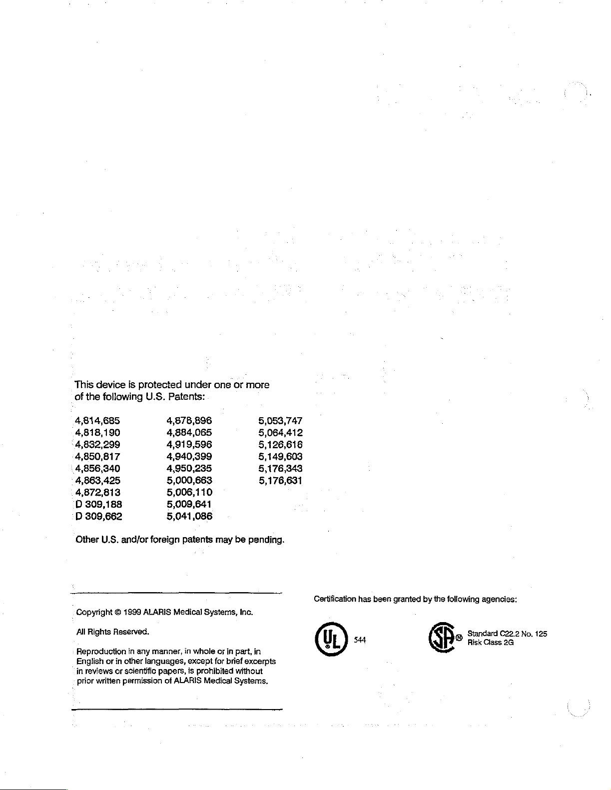
This
of
the
device
is
following
protected
U.S.
Patents:
under
one
or
more
4,814,685
4,818,190
4,832,299
4,850,817
_
4,856,340
4,863,425
4,872,813
D
309,188
D
309,662
Other
U.S.
and/or
Copyright O 1999
All
Rights
Reserved.
Reproduction
English
or
in
in
prior
reviews
or
written
other
scientific
permission
ALARIS
in
any
languages,
4,878,896
4,884,065
4,919,596
4,940,399
4,950,235
5,000,663
5,006,110
5,009,641
5,041,086
foreign
manner,
Medical
papers,
of
ALARIS
patents
in
except
is
may
Systems,
whole
or
for
prohibited
Medical
be
Inc.
in
part,
brief
excerpts
without
Systems.
5,053,747
5,064,412
5,126,616
5,149,603
5,176,343
5,176,631
pending.
in
Certification
has
(DE
been
granted
by
the
following
p
©
Standard
Risk
agencies:
C22.2
Class
2G
No.
125
Page 14
ALARIS”
Medical
Systems,
Inc.
IVAC®
Models
MedSystem
2860
Multi-Channel
Technical
Service
III"
and
Infusion
2863
Manual
Pump
MedSystem
Ill?
is
the
trademark
of
ALARIS
Medical
Systems,
Inc.
formerly
known
as
IVAC
Corporation.
Page 15
MedSystem
111%
Technical
Service
Manual
Copyright O 1999
This
document
possession
described.
authorization
.
This
Product
Diego,
Printed
Manual
does
Reproduction,
service
Support
CA
92126-5335,
in
the
part
from
manual
U.S.A.
number
ALARIS
contains
not
convey
ALARIS
is
subject
at
(800)
139981B
Medical
proprietary
any
rights
disclosure,
Medical
to
change
854-7128
attention
Product
Systems,
information
Systems,
ext.
to
or
use
without
6003,
Support.
Inc.
reproduce
other
Inc.
of
ALARIS
its
than
for
is
strictly
notification.
or
write
ALARIS
All
Medical
contents,
the
intended
forbidden.
For
Medical
Rights
Systems,
or
to
manufacture
purpose
current
Systems,
Reserved.
Inc.,
and
without
technical
Inc.,
its
receipt
or
sell
any
specific
information
P.O.
Box
or
product
written
please
85335,
call
San
Page 16
WARRANTY
ALARIS
“ALARIS
A.
Each
use
Medical
Medical
new
and
Medical
B.
Each
new
use
and
Medical
If
any
product
should
'
Diego,
this
expense.
packaged
repair
in
consequential
Systems
warranty
Furthermore,
responsible
any.
(a)
communicate
CA)
warranty,
The
and
facility
no
event
product.
shall
ALARIS
repaired
representative;
Systems™,
Systems”)
instrument
service
Systems.
for a period
to
accessory
service
Systems
to
shall
shall
this
for,
Medical
by
for a period
requires
determine
repair
product
postage
be
ALARIS
damages
This
not
warranty
any
anyone
Inc.
warranis
is
free
the
original
is
free
to
the
original
service
directly
the
appropriate
or
replacement
requiring
prepaid
at
purchaser's
Medical
in
connection
warranty
apply
loss
Systems
to
shall
or
damage
other
formerly
that:
from
defects
of
one
purchaser.
from
defects
of
ninety
purchaser.
during
with
the
service
by
purchaser.
risk.
Systems
shall
any
not
apply
product
than
IVAC®
in
material
(1)
year
in
material
(90)
days
the
applicable
ALARIS
repair
will
with the
apply
subsequent
arising
which
an
authorized
be
carried
should
to,
and
in
has
be
facility.
purchase
solely
connection
Corporation
and
from
the
and
from
the
warranty
Medical
Loss
liable
owner
ALARIS
been;
Systems
Except
out
at
be
returned
or
damage
for
or
to
the
Medical
ALARIS
or
(hereinafter
workmanship
date
of
delivery
workmanship
date
of
delivery
as
ALARIS
any
use
original
holder
with
the
Medical
period,
provided
in
incidental,
of
Systems
the
headquarters
Medical
promptly,
return
any
ALARIS
purchaser.
of
purchase
Systems
referred
under
under
normal
by
ALARIS
normal
by
ALARIS
purchaser
otherwise
Systems
properiy
shipment
indirect
Medical
the
product.
shall
not
or
use
service
to
as
(San
This
be
in
to
or
of
(b)
altered
product's
(c)
subjected
serial
(d)
improperly
written
This
warranty
obligations
not
give
person
with
the
ALARIS
in
stability
or
lot
instructions
or
or
grant,
to
assume
sale
or
MEDICAL
OR IMPLIED,
FITNESS
See
FOR A PARTICULAR
packing
inserts
anyway
to
number
maintained
is
liabilities
use
so
or
misuse
altered,
furnished
in
lieu
of
directly
on
behalf
of
ALARIS
reliability;
or
ALARIS
SYSTEMS
INCLUDING
for
international
as
to
affect,
negligence
effaced
or
used
by
of
all
other
Medical,
or
indirectly,
of
ALARIS
Medical
DISCLAIMS
ANY
PURPOSE
in
ALARIS
or
accident,
or
removed;
or
in
any
manner
ALARIS
Medical
warranties,
Systems
the
Medical
Systems
WARRANTY
OR
warranty,
Medical
or
which
other
Systems.
express
and
ALARIS
authority
Systems
products.
ALL
to
any
OTHER
OF
MERCHANTABILITY
APPLICATION.
if
applicable.
Systems
-
has
had
than
in
accordance
or
implied,
Medical
any
representative
other
liability
WARRANTIES,
judgement,
the
product's
with
and
all
other
Systems
in
connection
or
does
other
EXPRESS
OR
the
the
OF
iii
Page 17
The
purpose
trained
troubleshoot,
All
KEY
instrument.
This
manual
Summary,
the
instrument.
in
the
NAMES
Screen
Appendix
of
analysis
contains
this
and
are
Technical
and
repair
the
written
messages
guidelines
H,
for
MedSystem
Servcie
servicing
MedSystem
in
regular type
are
written
for
general
precautions
III?
Technical
Service
Foreword
Manual
of
microprocessor-controlled
user
M1?
Infusion
as
they
in
italics.
and
patient
is
to
appear
before
enable
System.
safety.
beginning
personnel
on
Manual
who
instrumentation
the
computer
We
suggest
any
maintenance
are
experienced
to
keyboard
you consult
or
and
maintain,
or
the
Safety
repair
on
Specific
applicable.
If
local
If
If
you
you
you
advisory
need
ALARIS
need
need
and
cautionary
Contacting
assistance
Medical
technical
Customer
Systems
assistance,
ALARIS
with the
Service
information
Medical
installation
Account
call
or
Parts,
Manager.
toll
free
call
is
contained
or
operation
(800)
toll
free
」
Systems
of
854-7128
(800)
throughout
Technical
MedSystem
extension
482-4822.
the
manual
Support
Ill
equipment,
6003.
where
contact
your
Page 18
:
Chapter
1:
INTRODUCTION
MAIN
TABLE
OF
CONTENTS
Chapter
contents.
Chapter
Chapter
for
the
Chapter
Chapter Three
after
Chapter
Chapter
operating
Chapter
Chapter
optimum
Chapter
One
contains
2:
PRINCIPLES
Two
MedSystem
3:
SYSTEM
repair
or
4:
MAINTENANCE
Four
efficiently
5:
CALIBRATION
Five
performance.
6:
TROUBLESHOOTING
general
provides
III.
an
overview
FUNCTIONAL
describes
calibration,
provides
contains
the
and
procedures
and
to
references
information
OF
OPERATION
functional
annually
detect
the
for
about
of
the
system
TESTS
tests
recommended
as
part
of
for
properly
need
for
calibrating
the
MedSystem
and
details
preventive
maintaining
repair
or
adjustment.
and
adjusting
Ill
the
principles
`
prior
to
maintenance.
the
the
and about
of
using
the
instrument
instrument
the
manual
operation
instrument,
to
keep
it
to
maintain
Chapter
possible
procedures
Chapter
Chapter
reassembling
and
Six
contains
malfunctions.
in
the
event
7:
REPAIR
Seven
contains
the
instrument,
subassemblies.
troubleshooting
References
of a malfunction.
detailed
and
are
for
step-by-step
procedures
included
removing
to
to
help
guide
procedures
and
installing
isolate
service
replaceable
and
identify
personnel
for
disassembling
causes
to
the
proper
and
components
of
Page 19
MedSystem
ili
Technical
Service
Manual
Appendix
This
appendix
instrument.
Appendix
This
appendix
depicting
Appendix
This
appendix
Appendix
This
appendix
useful
troubleshooting.
Appendix
in
MAIN
A:
TECHNICAL
contains
B:
REQUIRED
is a general
special
C:
RECOMMENDED
lists
D:
BATTERY
provides
performing
E:
ILLUSTRATED
TABLE
the
EQUIPMENT
listing
tooling
and
recommended
HISTORY
details
battery
OF
CONTENTS
SPECIFICATIONS
physical,
electrical,
AND SUPPLIES
of
required
equipment.
SPARE PARTS
spare
parts,
LOG
about
the
Battery
operating
PARTS
time
functional
LIST
and
equipment
as
well
as
History
checks,
(Continued)
mechanical
and
the
order
Log,
specifications
supplies,
numbers
which
contains
annual
of
as
well
as
figures
for
each.
information
maintenance,
the
and
This
appendix
each.
Appendix
This
appendix
Appendix
This
appendix
Appendix
This
appendix
the
manual.
Appendix
This
appendix
assembly
is
an
illustrated
F:
LIST
OF
provides a list
G:
GLOSSARY
defines
H:
SAFETY
provides
I:
SCHEMATICS
provides
and
the
power
listing
ABBREVIATIONS
of
the
abbreviations
OF.
TERMS
some
words
SUMMARY
general
supply,
board
safety
assemblies
along
of
instrument
and
terms
precautions
with
parts,
AND
an
ACRONYMS
and
which
may
that
and
schematics
interconnect
as
well
acronyms
not
be
are
not
diagram.
as
the
order
used
in
the
well-known
included
for
the
within
main
numbers
manual.
to
the
user.
the
electronics
for
text
of
Page 20
TABLE
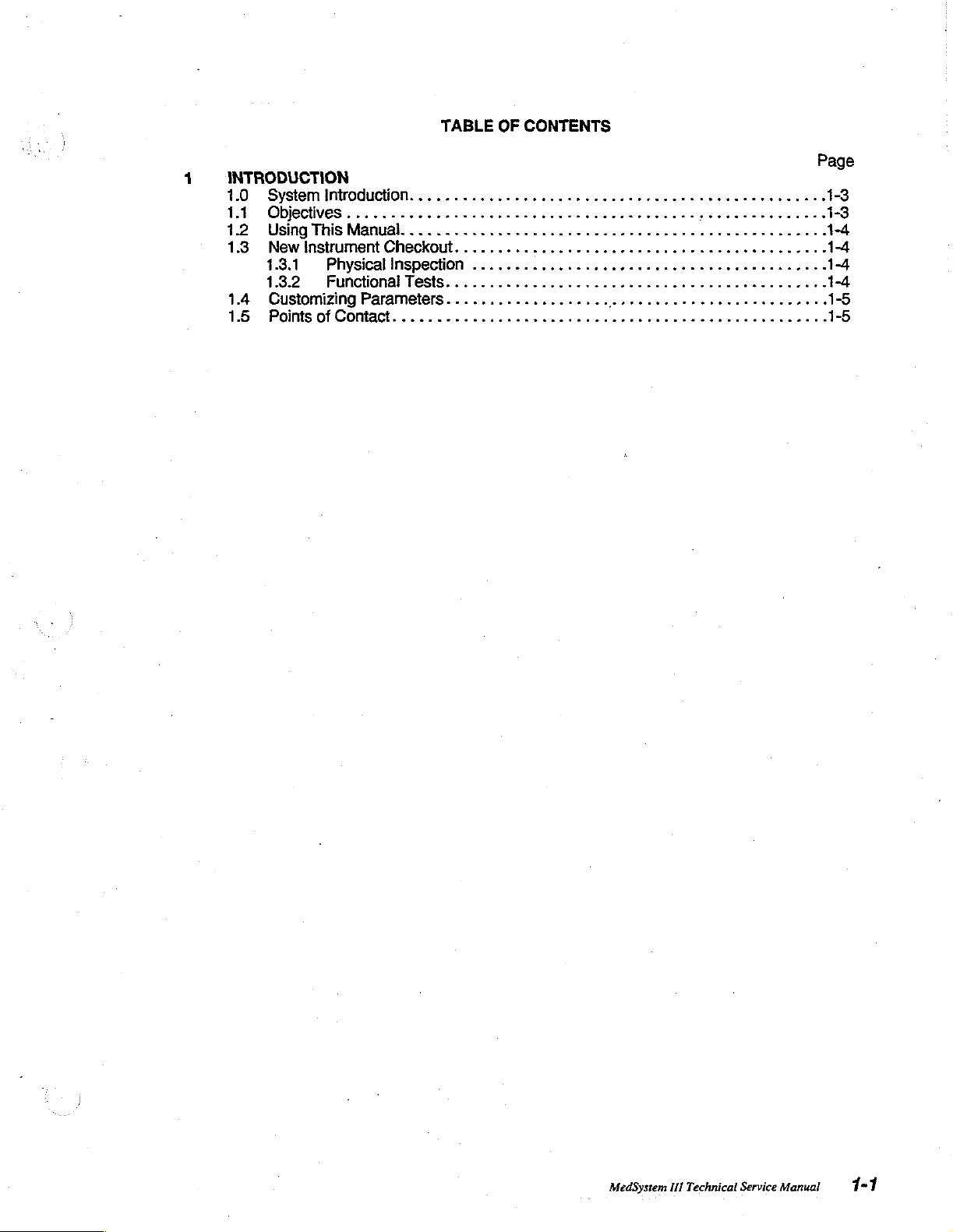
INTRODUCTION
1.0
Systeminiroducton........................
1.1
Objeciives................
1.2
UsinghisManual..........................
1.3
Newinstrument
1.3.1
1.3.2
1.4
Customizing
15
PointsofContaci.........................
oPhysicalinspection
Functionallesis.........................
Checkout.
.................
............................
Parameters...................
OF
CONTENTS
cee
00mm
444
00...
eserse
eee
0.0.
eee
ων
een
κών
eee
enes
ence
eens
нина
κενο ν 1-4
ώ
ον
ké
Page
1-3
1-3
14
1-4
14
1-5
1-5
MedSystem
III
Technical
Service
Manual
1-1
Page 21

Introduction
1-2
MedSystem
III
Technical
Service
Manual
Page 22
Chapter
1
Introduction
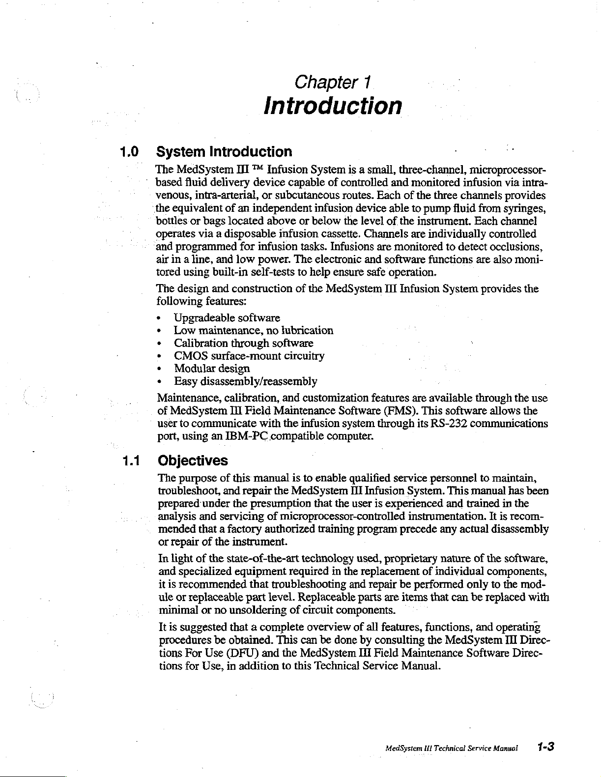
1.0
System
The
MedSystem
*
based
venous,
the
bottles
operates
and
The
fluid
equivalent
or
programmed
air
in a line,
tored
using
design
following
・
Upgradeable
»
Low
e
Calibration
*
CMOS
*
Modular
Easy
Maintenance,
of
MedSystem
user
to
communicate
port,
using
Introduction
II ™ Infusion
delivery
intra-arterial,
bags
via a disposable
and
built-in
and
features:
maintenance,
surface-mount
design
disassembly/reassembly
an
device
or
subcutaneous
of
an
independent
located
above
infusion
for
infusion
low
power.
self-tests
construction
software
no
through
calibration,
TI
software
Field
Maintenance
with
IBM-PC
compatible
capable
or
tasks.
The
to
of
lubrication
circuitry
and
customization
the
infusion
System
is a small,
of
controlled
routes.
infusion
below
the
cassette.
Infusions
electronic
help
ensure
the
MedSystem
Software
system through
computer.
and
Each
device
level
of
able
Channels
are
and
software
safe
operation.
III
features
(FMS).
three-channel,
monitored
of
the
three
to
pump
the
instrument.
are
individually
monitored
functions
Infusion
are
available
This
its
RS-232
microprocessor-
infusion
channels
fluid
to
detect
System
software
communications
via
provides
from
syringes,
Each
channel
controlled
occlusions,
are
also
moni-
provides
through
the
allows
intra-
the
use
the
1.1
Objectives
The
purpose
troubleshoot,
prepared
analysis
mended
or
repair
In
light of
and
specialized
it
is
recommended
ule
or
replaceable
minimal
It is
suggested
procedures
tions
For
tions
for
of
and
under
and
servicing
that a factory
of
the
the
or
no
be
Use
Use,
this
manual
repair
the
presumption
is
to
enable
the
MedSystem
that
of
microprocessor-controlled
authorized
training
instrument.
state-of-the-art
equipment
that
troubleshooting
part
level.
unsoldering
that a complete
obtained.
(DFU)
in
and
addition
technology
required
Replaceable
of
circuit
overview
This
can
the
MedSystem
to
this
Technical
qualified
HI
Infusion
the
user
program
used,
in
the
replacement
and
parts
components.
of
be
done
by
If
Service
service
System.
is
experienced
instrumentation.
precede
proprietary
repair
all
be
are
items
features,
consulting
Field
Maintenance
Manual.
personnel
This
and
any
actual
nature
of
individual
performed
that
can
functions,
the
MedSystem
to
maintain,
manual
trained
of
has
in
It
is
disassembly
the
software,
components,
only
to
the
be
replaced
and
operating
II
Software
been
the
recom-
mod-
with
Direc-
Direc-
MedSystem
HI
Technica!
Service
Manual
1-3
Page 23
Introduction
1.2
Using
This
Throughout
to
both
called
The
Each
principles
them.
ter 5 describes
bleshooting,
troubleshooting
This
manual
models.
Manual
includes
the
manual,
Where
out.
Technical
chapter
Service
is
clearly
of
operation.
Chapter 4 provides
procedures
and
includes a number
process.
ment.
The
appendices
A-
Technical
B - Required
C - Recommended
D - Battery
E-
Illustrated
E-
List
of
G - Glossary
H-
Safety
I-
Schematics
All
instructions,
each
chapter
tion.
It
is
suggested
ning any
type
included
Specifications
Equipment
History
Parts
Abbreviations
of
Terms
Summary
special
to
minimize
that
of
service
information
if
no
information
Manual
defined
on
the
model
number
is
specific
is
specifically
in
the
table
Chapter 3 discusses
both
routine
for
calibrating
of
Chapter 7 is a detailed
are:
and
Supplies
Spare
the
Log
List
Safety
Parts
and
notes,
the
need
on
the
Acronyms
and
illustrations
to
refer
Summary,
instrument.
Model
is
of
functional
and
annual
the
tables
to
Appendix
2860
and
Model
specified,
to
one
structured
contents.
the
model,
to
Chapter 2 discusses
tests
maintenance
instrument.
to
be
used
Chapter.6
as
procedure
are
integrated
multiple
H,
pages
be
reviewed
2863
pumps.
information
that
model
facilitate
and
how
number
ease
to
complete
procedures.
discusses
guides during
for
repairing
within
during a single
the
before
pertains
is
of
use.
the
Chap-
trou-
the
the
instru-
text
of
opera-
begin-
1.3
1.3.1
1.3.2
_
New
Physical
*..
*
+
Instrument
Inspection
Before
affected
Check
Check
found,
unpacking,
contents.
to
for
report
Functional
Refer
and
to
your
testing
of
Recommended
MedSystem
1H
Technical
Checkout
check
Report
ensure
any
Tests
institution's
that
all
physical
it
to
Customer
incoming
equipment
functional
Service
Manual
accessories
damage
policies
tests
the
shipping
any
shipping
Service.
for
are
container
are
to
the
instrument
specific
before
given
in
for
damage
included
to
in
or
requirements
use.
Chapter 3 of
damage
Customer
the
that
Service.
package.
accessories.
regarding
this
manual.
may
have
If
any
is
inspection
Page 24
Introduction
1.4
1.5
Customizing
Certain
customizing
Directions
Points
For
Customer
1-800-482-4822
For
Product
1-800-854-7128
MedSystem
For
of
parts,
disposables,
Service
technical
Support
is
desired,
Use.
Contact
information,
Parameters
II
operating
refer
or
repair
Department
assistance
Department
extension
6003
to
the
service,
parameters
MedSystem
telephone:
with
repair,
can
be
I
Directions
or
technical
customized
For
Use
training,
using
telephone:
and
FMS.
the
if
FMS
MedSystem
III
Technical
Service
Manual!
1-5
Page 25

Page 26
Page 27

Page 28
Chapter
2
2.0
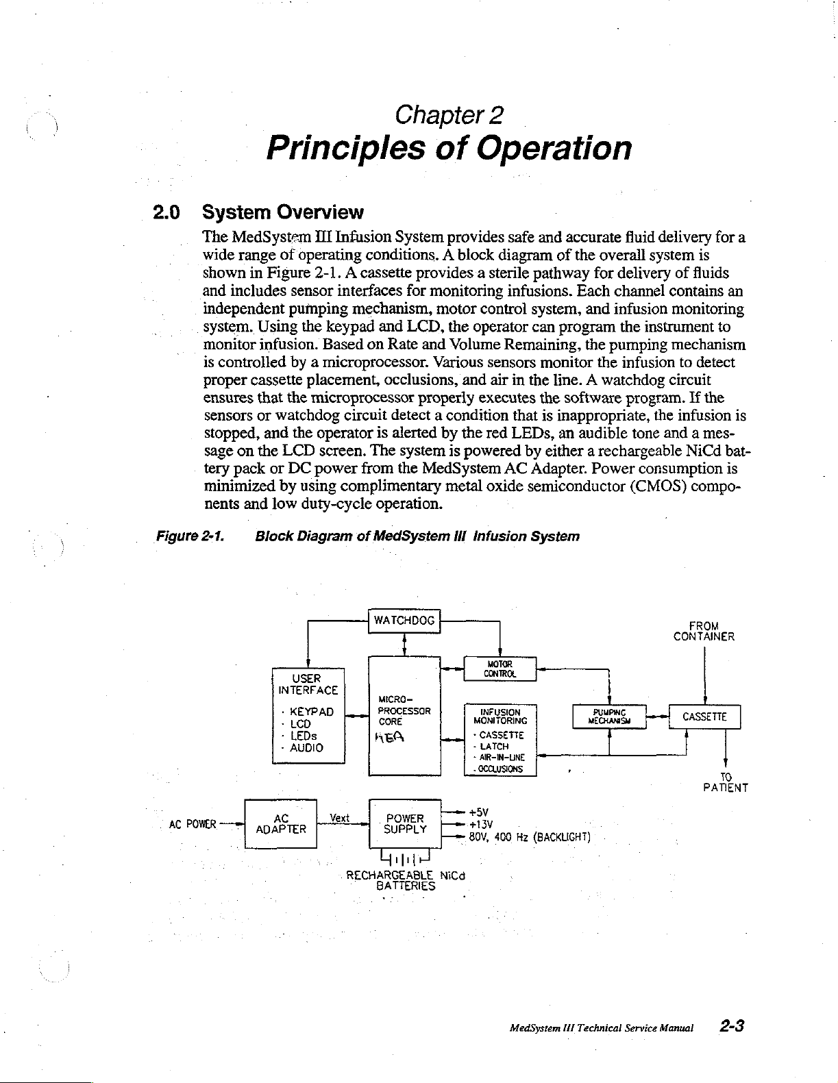
Figure
Principles
System
The
MedSystem
wide
shown
and
includes
independent
system.
monitor
is
controlled
proper
ensures
sensors
stopped,
sage
on
tery
pack
minimized
nents
2-1.
Overview
range
of
in
Figure
Using
infusion.
cassette
that
or
watchdog
and
the
LCD
or
by
and
low
Block
of
III
Infusion
operating
2-1. A cassette
sensor
pumping
the
Based
keypad
interfaces
mechanism,
by a microprocessor.
placement,
the
microprocessor
circuit
the
operator
screen.
DC
power
using
complimentary
duty-cycle
Diagram
System
conditions. A block
provides a sterile
for
monitoring
motor
and
LCD,
on
Rate
and
Various
occlusions,
properly
detect a condition
is
alerted
The
system
from
the
MedSystem
operation.
of
MedSystem
Operation
provides
the
Volume
and
by
the
is
powered
metal oxide
Ill
safe
diagram
pathway
infusions.
control
operator
system,
can
Remaining,
sensors
air
in
the
executes
that
red
LEDs,
by either a rechargeable
AC
Adapter.
semiconductor
Infusion
System
and
of
monitor
line. A watchdog
the
is
accurate
the
Each
fluid
overall
for
delivery
channel
delivery
system
contains
and infusion
program
software
inappropriate,
an
audible
the
pumping
the
Power
the
instrument
infusion
circuit
program.
the
tone
and a mes-
consumption
(CMOS)
for
a
is
of
fluids
an
monitoring
to
mechanism
to
detect
If
the
infusion
NiCd
is
bat-
is
compo-
POWER
AC
一
USER
INTERFACE
・
Ker
AD
:
-
LEDs
-
AUDIO
AC
ADAPTER
WATCHDOG
MICRO—
PROCESSOR
CORE
AEA
Vext
POWER
SUPPLY
Grup
RECHARGEABLE
BATTERIES
MONITORING
>
-
-
»
OCCLUSIONS
+5V
Lee
+13V
|
Bov.
NICO
MOTOR
CONTROL
CASSETTE
LATCH
АВ-М-ВМЕ
Hz
400
MEGHAN
(BACKLIGHT)
FROM
CONTAINER
CASSETTE
το
PATIENT
MedSystem
HI
Technical
Service
Manual
2-3
Page 29
Principles
The
main
sette
contains
brane
sealed
stroke
section
The
collar
securely
chassis
LD.
optics
ing
different
instrument
cally
of
Operation
functional
an
elastomeric
is
exposed
for
by a silicone
volume
between
of the
is
seats
in
the
instrument
also
approximately
the
in
sensor.
provide a code
cassette
chassis,
occludes
the
tubing
components
valving
piston
the
engages
sleeve
cassette
and
lower
To
detect
senses
types.
The
the
when
of
the
membrane
and
for
sensing
in
which
80
microliters.
tubing
housing
of
cassette
the
identification
that.can
cassette
slide
link
the
cassette
cassette
between
are
two
pressure.
the
plastic
Air
collar.
the
instrument
placement,
(I.D.)
be
used
in
slide
clamp
to
close
is
removed
shown
rigid
The
piston
is
sensed
and
the
optomodule
optics
future
applications
latches
the
pump
from
in
Figure
plastic
pumping
holds
parts.
is
inserted.
in
the
outlet
the
of
the
the
cassette
latch,
and
the
instrument.
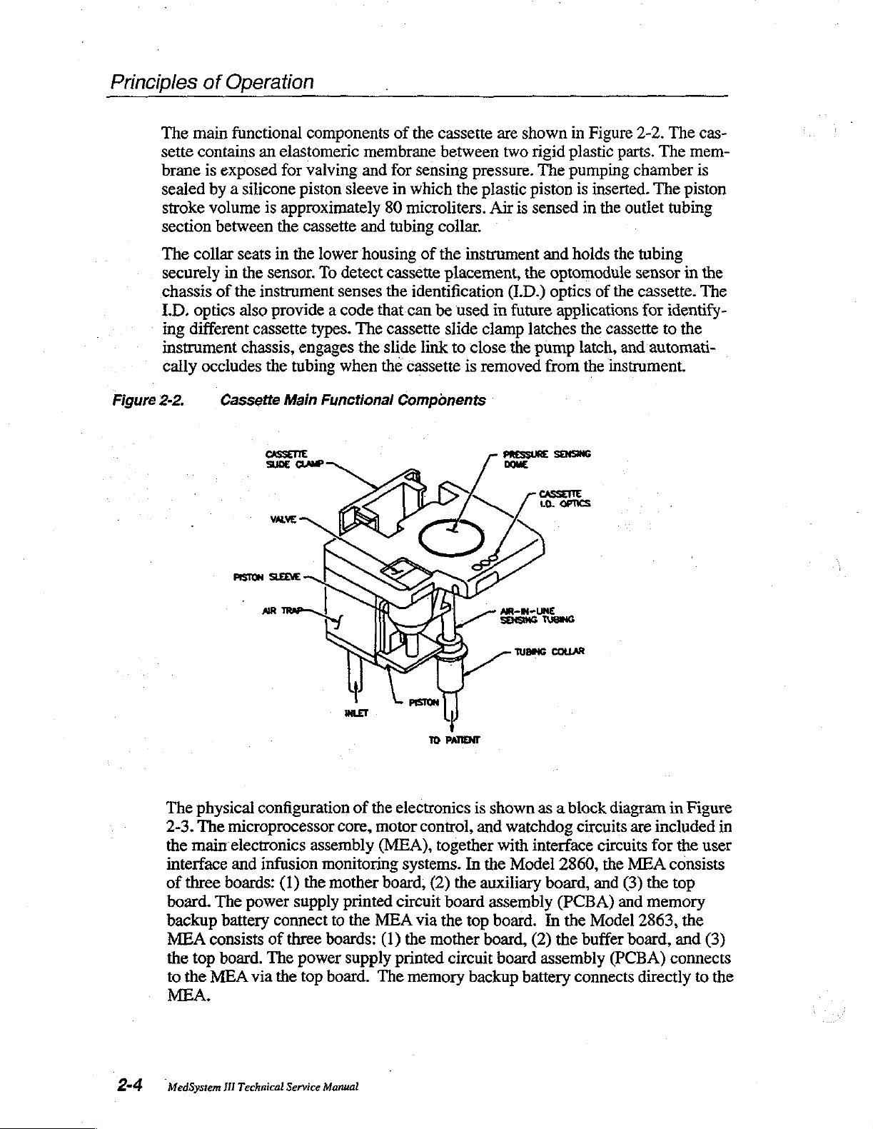
2-2.
The
The
mem-
chamber
The
piston
tubing
tubing
sensor
cassette.
in
for
identify-
to
the
automati-
cas-
is
the
The
Figure
2-2.
The
2-3.
the
Cassette
physical
The
maim
interface
of
three
boards:
board.
backup
MEA
the
to
The
consists
top
board.
the
MEA
battery
MEA.
Main
Functional
configuration
microprocessor
electronics
and
infusion
(1)
power
supply
connect
of
three
The
via
the
core,
assembly
monitoring
the
mother
printed
to
boards:
power
top
board.
of
the
motor
(MEA),
board,
the
MEA
(1)
supply
The
Components
electronics
is
control,
together
systems.
circuit
via the
the
printed
memory
In
(2)
the
board
top
mother
circuit
backup
shown
and
the
auxiliary
as a block
watchdog
with
interface
Model
assembly
board.
board,
(2)
board
assembly
battery
circuits
2860,
board,
(PCBA)
In
the
the
buffer
connects
diagram
are
circuits
the
MEA
and
(3)
and
Model
board, and
(PCBA)
in
Figure
included
for the
user
consists
the
top
memory
2863,
the
connects
directly
to
in
(3)
the
2-4
MedSystem Ш Technical
Service
Manual
Page 30
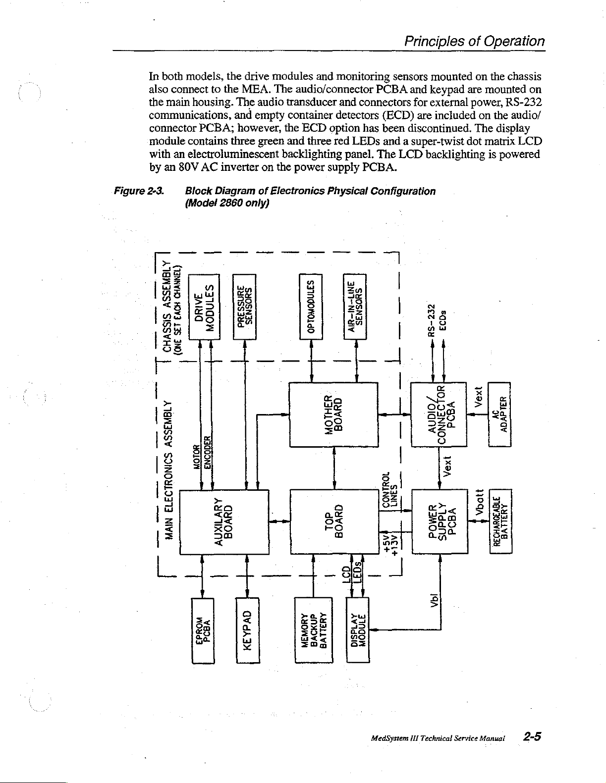
In
both
models,
also
connect
the
main
housing.
communications,
connector
module
with
by
contains
an
electroluminescent
an
80V
to
PCBA;
AC
inverter
the
the
drive
MEA.
The
audio
and
empty
however,
three
green
on
modules
The
transducer
the
backlighting
the
and
audio/connector
container
ECD
option
and
three
red
power
supply
monitoring
PCBA
and
connectors
detectors
LEDs
panel.
(ECD)
has
been
and a super-twist
The
PCBA.
Principles
sensors
LCD
mounted
and
keypad
for
external
are
included
discontinued.
backlighting
of
Operation
on
the
chassis
are
mounted
power,
The
dot
RS-232
on
the
display
matrix
is
powered
on
audio/
LCD
Figure
2-3.
lag
dE
|
|
WS
lw
«δις
jus
Be
пы
|
ー
|
>
그
E
č
a
<
[2
8
=
o
|
E
o
之
£
=
|
Block
(Model
|
(BS)
oo]
=
ge
Js
O)
as
二
|
Diagram
2860
only)
lu
še
Da
a
|
jeg
ce
SE
=5
38
<
of
Electronics
Physical
a y
5
8
8 | [15
と
5
5%
i |
za
ah
<
ge
τας
55
og
=
e
at
은
E
1
C
Configuration
|
|
|
|
|
4
3
|
En
5
|
35
|
22|
++
EDs
N
38
19
yu
| |
gs
ち < |
205
SHE
250
そら
8
я
2
|
Ex
Sam
Lo
a
Vbl
S|
っ
(E
고
|
LIRE
Bui
ЕН
ES
回
G
と
a
<
a
EPROM
PCBA
KEYPAD
MEMORY
BACKUP
BATTERY
MODULE
DISPLAY
MedSystem
Ill
Technical
Service
Manual
2-5
Page 31

Principles
of
Operation
Fluid
Delivery
|
~
è
Proper
correct
after
ponents
personnel.
Fluid
is
delivered
module.
The
elastomeric
moved
„system
by a cam
the
connected
a
track
rocate
rotates
shaft
power
Each
valves
back
is
shown
in
cam
face
in
the
when
the
bearings
is
removed
of
to
cam
information
|
pump
operation
replacing
or
the
to
the
channel
the
pump
membrane
and
forth by
in
Figure
the
drive
module.
properly.
the
pump
side
of
the
the
cam
is
via
an
for
support,
from
for
controlling
WARNING
latch
and
valve
of
the
instrument.
certain
pump
patient
has
are
in
The
shaft.
cam,
rotated: A direct
elastomeric
the
drive
components.
latch
should
by a reciprocating
an
independent
formed
the
valve
the
pumping
2-4.
cassette
Follower
by
area
The
valve
Return
piston
springs
causing
belt.
and a one-way
motor.
fluid
An
delivery.
actuator
actuators
of
mechanism. A functional
actuators
bearings
the
current
The
encoder
heights
Heights
only
be
drive
module
in
the
cassette.
ensure
is
captured
attached
pump
latch
(DC)
drive
clutch
on
are
must
Removal
performed
piston
the
chassis
The
and
cassette
that
by
and
motor
module
to
prevent
the
cam
necessary
be
adjusted
of
drive
by
pump
mounted
powered
compressing
cassette
diagram
piston
the
valve
the
pump
to
the
pump
cassette
in
the
housing
backdriving
shaft
provides
for
com-
trained
by a drive
to
the
chassis.
piston
of
are
operated
actuators
latch
which
shaft
engage
piston
drive
to
module
includes
when
position
the
is
this
follow
is
recip-
cam
Figure
2-4..
Functional
DRIVE
MODULE
DRIVE
BELT
we
am
Diagram
MOTOR
」
4
o
|
of
.
Peston
Pumping
çimli
DNCODER
É
CASSETTE
Mechanism
m
CSS
nus
ONE-mAY
САМ
CAM
FOLLOWER
VALVE
PUMP
cusica | Tee
Encuees
BEARNGS
ACTUATOR
LATCH
in
tre
housing.
NOTE:
MedSystem
Arrangement
HI
Technical
and
Service
scaling
Manual
of
components
may
be
different
than
actual
configuration.
This
is
for
clarity.
Page 32

Principles
of
Operation
Cassette
turned
at
the
nal
During
slot
the
is
pushed
the
the
against
closing
sis
patient.
Sensors
together
fluid
Pumping
valve
by
closes
overlapped
closed.
chamber
installation
on
beginning
from
the
installation
in
the
side
that
in,
pump
slide
clamp
the
off
also
unclamps
The
in
with
delivery.
begins
is
closed
retracting
the inlet
Fluid
(see
prepares
and a cassette
of
the
fill
encoder,
allows
(see
front
of
the
slide
engages a slot
the
tab
pushes
latch.
The
cassette
also
engage
chassis.
the
tubing
the
to
This
fluid
pathway.
the
patient-side
collar
optomodule
the
air
sensor's
by
positioning
and
the
the
piston
valve
and
ensure
is
Figure
then
the
delivered
2-6B).
the
is
not
installed,
stroke.
the
Figure
2-5), a tab
link.
in
the
the
slide
piston
holders
forces
the
Pushing
is
then
detect
detection
inlet
valve
(see
Figure 2-6A).
opens
fiuid
pathway
by
system
The
home
pump
The
back
latch
movable
of the
link,
is
now
in
the
valve
the
tubing,
secured
cassette
of
the
valves
is
opened.
the
outlet
between
advancing
for
fluid
delivery.
the
cam
is
position,
to
easily
on
the
cassette
jaw
slide
which,
held
in
firmly
chassis
actuators
cassette
allowing
in
the
air-in-line
placement
fluid,
signals
to
fill
the
The
pumping
Once
the
valve.
the
Opening
the
piston
When
rotated
which
capture
slide
of
the
pump
link.
As
the
turn,
closes
by
the
to
hold
the
against
slide
clamp
fluid.to
sensor
and
pump
that
pumping
chamber
and closing
container
toward
the
to
the
"home"
is
indicated
the
cassette
clamp
latch
cassette
the
pump
cassette
the
cassette
in
toward
be
delivered
by
latch
the
channel
chamber.
chamber
is
filled,
and
patient
the
instrument
position
by a sig-
piston.
engages
has a post
slide
movable
latch.
Tabs
body
valve
the
to
the
the
operator.
closure.
is
ready
The
is
then
the
cam
of
valves
is
always
bottom
of
is
a
on
clamp
jaw
of
on
firmly
area,
chas-
This,
for
outlet
filled
is
the
Delivery
back
ing:
stroke,
ing
results
counter
grammed
and
mines
turned
The
pulse
voltage
13V
controlled
stroke.
tains
rate
from
the
(1)
sensing
(2)
sensing
the
home
in a volume
that
by
measured
the
appropriate
on.
controller
width
circuit. A drive
is
used
by
This
fluid
delivery
experienced
is
regulated
encoder.
whether
the
incremental
position.
resolution
accumulates
the
user,
is
encoder
motor
performs
is
loaded
for
logic
signal
during
into a programmable
rates
greater
circuits;
is
referred
rate
infusions.
by
varying
An
encoder
the
pump
The
delivery
of
encoder
converted
counts, a feedback
pulse
these
calculations
voltage
than
using
to
at
the
programmed
the
on
the
channel
motion
stroke
0.5
microliters.
counts
to
required
width
of
5V
is
275
ml/h.
an
optical
as
DEL.
used
duty
cycle
cam
shaft
is
in
the
during
is
divided
The
for
each
encoder
control
which
is
every
interval
for a rate
Valving
encoder
This
closed-loop
value
of
the
motor,
has
several
fill
stroke
fluid
delivery,
into
160
microprocessor
channel.
algorithm
the
three
timer
and
signal
The
counts.
duration
seconds.
that
of
275
pump
that
system
despite
the
based
functions,
or
in
the
delivery
and
(3)
increments,
reads
infusion
From
the
in
the
software
that
the
motor
The
calculated
controls
ml/h
filling
marks
the
or
less,
phases
the
accurately
varying
loads
on
feed-
includ-
determin-
which
a
rate,
pro-
required
deter-
is
drive
and
are
delivery
main-
that
are
MedSystem I Technical
Service
Manual
2-7
Page 33

Principles
of
Operation
Figure
2-5.
PUMP
STATIONARY.
PUMP
MOVING
SUDE
Cassette
SHAFT
LINK
AW
LATCH
JAW
Installation
A.
CHASSIS
INSERT
:
.
CASSETTE.
CASSETTE
CASSETTE
SLIDE
PISTON
CLAMP
2-8
MedSystem
Il
Technical
C.
Service
Manual
CASSETTE
ENGAGED.
2
~
Z
Page 34

Principles
of
Operation
Figure
2-6.
Pumping
CHASSIS
RIGID
PLASTIC
OF
CASSETTE
Chamber
OUTLET
ACTUATOR
ZA
SILICONE
DIAPHRAGM
PISTON
BY
VALVE
RETRACTED
PUMP
LATCH
L
TI
VALVE
CLOSED
Th
U
クノ
¡EOS
ELİA
—_
7
AN
クン ン シン
クン
ンジ
:
MOTUATOR
DSS
Li
[piston
Gee
N
BO-p!
SLEEVE
PISTON
VALVE
FLUID
N
CHAMBER
ACTUATOR
FLUID OUT
RIGID
PISTON
BY
PUMP
me
A)
PLASTIC
ADVANCED
LATCH
A.
FILL
À
K
STROKE.
Tan
LAA
ACTUATOR
E
.
3
CLOSED
nů
B.
DELIVERY
STROKE.
MedSystem
III
Technical
Service
Manual
2-9
Page 35

Principles
of
Operation
2.2
Microprocessor
Figures
nents
unless
A.
A
tions.
tions,
trollers,
ates
Моде]
24.576
B.
The
trol
the
PLD
devices
address
address
maps
2-7
and
2-7a
connected
otherwise
to
noted.
Microprocessor
Z180
8-bit
microprocessor
On-chip
two
and
the
6.144
2863,
MHz
Address
functions
16-bit
programmable
an
interrupt
MHz
an
on-chip
external
Decoding
microprocessor
lines.
In
the
Model
Z180
via
logic
is
connected
on
the
microprocessor
decode
bus and
generate
circuits
four
the
the
in
to
addresses.
Core
are
block
bus.
All
include.a
controller.
system
bus
the
the
control
clock
oscillator
crystal.
consists
2860,
address
address
in
the
diagrams
components
system
monitors
memory
reload
In
the
from a 12.288
generates
of
eight data
devices
bus
two
lines.
on
decode
bus
and
are
gate
In
both
of
the
microprocessor
are
mounted
and controls
management
timers,
two
Model
2860,
MHz
the
12.288
lines,
the
microprocessor
programmable
four
control
accessed
arrays.
by
The
models,
unit,
direct
an
external
MHz
20
address
logic
lines.
the
Z180
gate
arrays
memory
and
on
the
MEA
many
serial
memory
on-chip
crystal.
system
lines,
bus
device
In
the
via
are
and
input/output
the
compo-
PCBA,
instrument
communica-
access
oscillator
are
Model
logic
con-
gener-
In
the
clock
from
and
four
accessed
(PLD).
2863,
in
the
connected
func-
a
con-
by
This
to
the
(/O)
C.
Memory
The
Z180
can
access
unit.
Currently,
ory,
and
32
access
provide
This
memory
dual
additional
EPROMs
battery-backed
rity
of the
16-bit
cyclical
watchdog
D.
Cyclical
The
CRC
CCITT
stored
tions
ment
ROM)
E.
calculation.
in
RAM,
link, for the
ROM
result
Input/Output
the
kilobytes
(RAM).
data
memory
are
mounted
to
program
redundancy
alarm.
Redundancy
engines
to
(Read
in a watchdog
one
megabyte
instrument
(Model
In
paths
in
hardware
is
on
an
retain
information
and
data
are
hardware
The
CRC
detect
errors
power-on
Only
Memory)
(1/0)
Ports
of
memory,
uses
256
2860)
the
referred
EPROM
or
Model
to
to
56
2863,
ensure
as a shadow
board
when
stored
check
Check
in
memory
(CRC).
(CRC)
implementations
engines
in
RAM
alarm.
are
messages
self-test,
contents.
using
kilobytes
kilobytes
an
additional
safe
that
plugs
the
instrument
is
checked
Corruption
(Model
of
used
to
received
and
to
Detecting
the
memory
of
EPROM
(Model
32
operation
RAM.
In
into
the
is
by
of
data
2863
ONLY)
an
eight-bit
detect
ensure
corruption
over
the
the
memory
management
for
program
2863)
of
of
random
kilobytes
software
both
models,
MEA.
turned
off.
software
results
in a fault
parallel
of
serial
communica-
integrity
errors
mem-
of
RAM
functions.
the
The
RAM
The
integ-
which
uses
or
CRC-
system
of
(RAM,
data
the
instru-
is
a
|
2-10
In
the
Model
output
as
output
MedSystem
lines
for
ports,
HI
Technical
2860,
three
interfacing
and
the
third
Service
Manual
82C55
to
the
is
integrated
circuits
microprocessor.
used
as
an
input
ICs)
Two
port.
provide
of
the
digital
82C55
ICs
input
and
are
used
Page 36

In
the
Model
or
monitoring
F.
Real-Time
The
RTC
provides
battery
G.
when
Communications
2863,
two
digital
Clock
time
the
instrument
gate
lines.
(RTC)
and
arrays
date
is
provide
information.
turned
off,
input
This
Principles
and
output
IC
is
powered
of
ports
by
Operation
for
controlling
the
backup
Serial
interface
els.
-10V
the
communication
IC
translates
This
interface
required
audio/connector
H.
Motor
In
the
IC
containing
In
the
using
models,
I.
Encoder
The
encoder
and
for
is
decoded
quadrature
In
the
8-bit
for
each
J.
Analog-to-Digital
Pulse
Model
Model
three
2860,
three
2863,
16-bit
one
independent
Counters
provides
controlling
by a Hewlett-Packard
decoding
Model
binary
2863,
up/down
pumping
uses
between
chip
has
for
RS-232
PCBA.
Width
Generator
pulses
16-bit
pulses
programmable
incremental
motor
and a 12-bit
Gate
Array 1 includes a circuit
counter
channel.
(A/D)
the
Channel 0 serial
the
microprocessor
an
on-board
charge
communications.
for
controlling
programmable
for
controlling
counters
counter
is
motion
actuation.
the
counters
the
configured
provided
data
In
the
Model
HCTL2000
binary
to
determine
Converter
up/down
and
port
CMOS
pump
The
RS-232
motors
configured
motors
for
IC.
are
each
for
determining
2860,
This
counter.
for
the
encoder
Multiplexer
on
the
microprocessor.
levels
that
generates
signals
are
generated
generated
are
in a one-shot
in a one-shot
pumping
channel.
the
quadrature
integrated
quadrature
count.
There
and
RS-232
the
+10V
connected
using
an
in
Gate
mode.
volume
encoder
circuit
decoding
includes
is
one
An
lev-
and
to
82C54
mode.
Array
In
1,
both
infused
output
and
an
circuit
Analog
This
ble
Conversion
plexer
Model
analog
tional
K.
When
tents
by a 2/3
disabling
1CL7673
ing
1CL.7673
signals
converter
control
is
controlled
2860,
input.
24
channels
Battery
the
instrument
of
RAM
A-size
chip-selects
automatic
on
which
is
are
sampled
contains
logic. A successive
time
is
approximately
by
an
external
In
the
Model
of
analog
Backup
Circuit
is
and
powers
Lithium
battery-backup
voltage
referred
is
to
by
an
eight-channel
the
microprocessor
multiplexer
2863,
input,
turned
the
RTC.
primary
to
the
RAM
highest)
as
Vbb.
the
microprocessor,
multiplexer
approximation
100
microseconds.
via
an
external
for a total
off,
the
Power
cell.
and
switch
to
the
circuit
provides
battery
for
If
Vcc
falls
RTC,
which
connects
RAM
and
using
an
and
microprocessor-compati-
method
the
multiplexer
of
backup
battery
address
an
29
A/D
below
is
used
The
eight-channel
bus
additional
circuit
channels.
circuit
backup
4.6V, a comparator
prevents
either
RTC
power
MedSystem
Ii
Technical
8-bit
A/D
by
this
converter.
(three
bits).
32
provides
maintains
(Vback)
corruption.
Vcc
or
Vback
pin.
The
output
Service
Manual
converter.
multi-
In
the
channels
the
is
provided
an
addi-
con-
of
trips,
An
(depend-
of
the
2-11
Page 37

Principles
Figure
2-7,
of
Operation
Block
(Model
Diagram
2860)
of
Microprocessor
and
Components
Connected
to
the
Bus
DA
AHVWIHd
Μη
T
ER
|
ΗΟΗΜ5
AUILIVO
ἀΠλογ8
Ta
ET
ELSA
am
310004
n
09
1
8300230
00603
553800
뷔
[20610
ONA
IN
7038
‧
WVA
8
X
MZE
5089
80SS
コ
90dd083IW
[
#34408
ны
GAVOHAJM
4300930
сев
UJLNJANOJ
80809qv
G/Y
319yNWV8908d
а
D
SYILNNOI
0002494
Gua)
ons
TINNVHO=ZE
YIKTI
2-12
MedSystem
HI
Technical
oe
s
wt
Service
(OML)
Manual
HOSS390UdONDIN
OBIZ
S1M0d
cone
0/1
(33441)
Page 38

Principles
of
Operation
Figure
2-7a.
σολ.
|
Block
Bus
sl
un
OA
HOLMS
ALIVE
TRE
d0YOVB
Diagram
(Model
1.
|
SAVHUV
TRL
VO
1
|
E
WOMd33
8
x
8
of
2863)
370001
m
027
|
pashan
|
4300930
S63M00V
p
|
Doro
00101
ame
nou
aa
(om)
x
ZE
pura
om)
OML
Microprocessor
Wa
8
X
MODVHS
Zr
ELES
SAB
VOSSITONAOMIN
2
880
310
and
Components
ヒレ
|
ーー
334408
ニー
ゴロ
|
j
saajanoa
0/v
|
4
>
|
newwwapola
—
ニー
women
πι
|
|
beget
|
|
918090
|
|
Ì
|
2090907
|
|
10HS-3ND
AVN9V
319
SU3LNNOS
|
|
||
Savdav
zal
vo
|
|
|
厂
一
一
一
一
一
一
一
一 一
一
一
Ат
| |
Connected
|
| |
| |
PAIE
TON
六
à
AVUUY
一
319
I
|
00
9089
上
NNyHo-Ve
to
the
dOSSIIO
0812
BEN
||
|
MedSystem
|
Ill
Technical
Service
Manual
2-13
Page 39

Principles
of
Operation
2.3
Figure
Watchdog
The
watchdog
microprocessor.
logic
circuitry
2-8.
Block
Diagram
=
le
Bão
Br
circuit
(see
+
The
Figures
г
is
circuit
of
.
an
independent
consists
2-8
and
Watchdog
=
Ag
TE]
monitor
of a one-shot,
2-8a).
Circuit
E
8
191
(Model
ol
(es
ss
that
ensures
an
oscillator/ripple
2860)
.
||
5
=>
E
safe
operation
]
of
counter,
5
8
に
=
=
the
and
|
Е
|
Bale
RE
24
Awe
sel
НН
|
E
|
eo]
Veo
UPRESET
>
pal
|
|
p:
3
Be.
=
—
=
2-14
ft
MedSystem
SAB
III
Technical
YOSS3DONJONDIN
Service
Manual
1
Page 40

Principles
of
Operation
Figure
2-8a.
E
き
Block
Diagram
>
>
E
n
lez
=
20
358.
2u
A
m
Sa
a
と
5
wr
BO
aw
we
us
a
=
<
8
~
E S
Za | É
Ses
de
=
S
=|
=
=
2
of
Watchdog
Y
に
o
=
5
8
Lit
=
=
3
io
xn
Sk
5
lu
88
Sa
a
>
Circuit
E
=
2 3
<
5
o
8
x
©
5
(Model
μα.
a
노호
SE
ru
EP
Ses
=56
o
a
2863)
o
을 =
=
=
à
|
5
in
5
8
>
|
o>
ur
Sa
as
a
8
È
=
TTT
8
E
3
Se
ビビ
så
8
3
5
=
>
sg
nas:
=
:
|
i
i
=
È
a
E
S
=>
=
PIE
|
一
[x
<
È
Г.
|
보
<
|“
TETE
|
|
Model
the
watchdog
to
the
lee
|=
|
{
In the
During
generating a non-maskable
power
Bw
asv
sus
=
O
|
SNE
YOSSIIONTONIIN
2863,
motors
7
LIS
ia
(liz
|
NE
4
>
the
watchdog
circuit
and
holds
me
by
o
ας
=
人
circuit
test,
the
interrupt
the
トイ
|
|
İBS
|
|
UZ
is
counter
(NMJ)
system
コー
r
E
o
in
ビィ
©
35|
pet
9"
EX
ZE
=
g
3
JA.
completely
is
not
to
the
microprocessor.
reset.
MedSystem
|
TI
I
li
tested
reset-and
Logic
III
Technical
in
Gate
—
i
|
i
|
i=
|
|
during
Q14
power-on.
will
go
This
Array 2 allows
Service
Manual
high,
shuts
2-
off
15
Page 41

Principles
the
watchdog
counter
erate a second
and
holds
therefore,
In
both
ing
power-up.
In
the
produces a constant
logic
disables
LEDs.
The
WQUAL
actions
a
high
rect
frequency.
code
100H
shot.
the
software
actions
resets
of
Operation
to
is
not
periodically
NMI
the
system
the
only
models,
If
Model
generates
level
256)
via
The
the
2860,
an
the
motors,
signal
must
occur
on
the
If
or
watchdog
the
address
output
must
generates
counter.
be
reset
once
after
to
in
action
the
power-on
the
software
logic
audio
NMI
reset,
the
microprocessor,
reset.
possible
holds
tone,
to
the
The
reset
fails
the
and
the
microprocessor
produces a constant
is
generated
to
generate
signal
this
signal
decoding
of the
write
the
signal
alarm
one-shot
to
WD
WARN
is
not
occurs.
/O
address
WQUAL.
the
logic,
goes
the
power-on
Q14
output
watchdog
is
to
tum
circuit
to
reset
will
which
circuit
off the
initializes
the
counter, a special
microprocessor
turns
on
the
keypad
and
by
the
software
WQUAL
to
ensure
correct,
Next,
which
high
1FFH.
The
audio
tone,
signal.
the
then
either
the
software
generates a trigger
for
90
microseconds,
The
rising
test.
After
the
go
high
again.
shuts
off
power
cannot
be
instrument.
elements
in
reset,
disables
LEDs.
holds
the
output
and
turns
to
reset
the
First,
the
counter
combination
edge
is
an
instrument
writes
of
the
first
reset,
if
This
will
to
the
motors
reset a second
of
this
system
alarm
In
on
counter.
software
operating
10
pulse
of
WQUAL
is
the
the
Model
ports
all
the
Three
fault
VO
for the
during
these
triggered.
motors,
in
keypad
must
at
the
(event
address
which
two
signal
the
gen-
time;
dur-
2863,
reset,
detect
cor-
one-
time
Failure
counter
or
rising
ing
the
on
Model
LCD,
In
the
The
watchdog
detected,
logic,
verters
gered,
WTCHDG
keypad
During a watchdog
normal
(VOL1,
the
tinuous
generated
to
reset
reset
input
200
milliseconds
edge
of
the
system
UPRESET
all
six
of the
2863,
the
turns
on
both
models,
instrument.
power-off
conditions.
software
asserting
on
the
the
microprocessor
input
controls
operation,
VOL2,
watchdog
audio
by
the
Q14
reset
line
keypad
UPRESET
all
the
logic
the
power
power-down.
and
PLD
tone
the
counter
must
be
(Model
causes
the
signal
holds
the
LEDs,
six
of the
only
action
circuit
During
generates
OFF
signal
supply
cannot
to
the
power-off
alarm,
audio
the
volume
TOUT).
(Model
at
the
highest
ripple
counter.
circuit
pulsed
and
front
can
2860)
results
high
2863),
output
in
holding
once
every
otherwise,
of the
latch
producing a watchdog
output
line
normal
the
from
When
ports
and
shuts
holds
that
power-down
signal
high.
some
panel
can
operation
This
the
MEA.
LEDs,
be
CSPWROFF
generate
logic
is
instrument
and
frequency
the
watchdog
or
in
Gate
volume.
(8255)
off
the
of
performed
the
signal
After
the
high;
produces a continuous
Array 2 (Model
The
the
system
100
milliseconds
the
output
(WTCHDG)
alarm.
in
reset,
power
the
and
to
output
shuts
off
by
instrument
when
an
ON/OFF
via
the
disconnects
the
watchdog
CSPWROFF
and,
the
HOFF
are
microprocessor
circuit
watchdog
triggers,
tone
line
Q14
to
In
blanks
the
motors.
ports
power
the
operator
under
address
the
signal.
2863)
WCHAUD
in
reset.
The
(Model
oscillates.
go
high,
generat-
the
Model
the
in
reset,
to
either
keypress
LCD,
In
the
dims
the
motors.
is
to
normal
2860,
turn
decoding
SV
and
13V
circuit
signal
audio
has
In
this
case,
from
tone.
controlled
logic
circuits
produce a con-
signal
2860)
The
turns
the
off
or
is
con-
trig-
the
the
Under
in
is
2-16
MedSystem
III
Technical
Service
Manual
Page 42

Principles
of
Operation
2.4
User
A.
The
control
keys.
(KBDINT*)
whether a function
9a).
Interface
Keypad
keypad
When a key
The
circuit
switches
interrupts
Circuit
consist
is
to
the
KBDINTCLR.
The
ON/OFF
formed
is
generated
detector.
The
function
Model
debounces
akeypress.
keypress.
The
depressed
from
2863)
2860,
KBDDA
the
bits
key
is
by a resistor
from
the
The
HOFF
key
switch matrix
and a keyboard
key
presses,
During a keypress,
Interrupts
is
sampled
or
released.
decoder
of
to
the
data bus.
provides
controls
of a separate
pressed,
the
interface
microprocessor
key
or
the
ON/OFF
are
cleared
separate
capacitor
debounced
also
from
goes
by
the
(RC)
signal,
to
the
is
decoder
decodes
are
generated
via
The
the
microprocessor,
the
the
an
input
location
for
operating
ON/OFF
which
key
key and a matrix
circuit
then
was
microprocessor
the
function
time
constant
HOFF,
watchdog
connected
in
Gate
key
matrix,
KBDDA
from
the
port
of the
using
key
by
power-off
to a 74C923
Array 2 in
and
line
leading
to
determine
keypress
five
the
instrument.
generates
reads
an
pressed
(see
through
matrix.
and
Schmitt
latching
informs
goes
high
and
trailing
whether
in
the
(Model
of 10
an
interrupt
input
port
Figures
output
Debouncing
trigger.
the
output
logic
and
keyboard
the
Model
the
microprocessor
for the
edges
the
matrix
is
2860)
The
keypad
function
to
determine
2-9
and
port
is
per-
An
interrupt
of
an
edge
an
input
port.
decoder
2863
duration
of
key
communicated
or
four
in
which
of
KBDDA.
is
(Model
2-
the
of
the
A
foil
layer
in
the
from
the
shield
housing,
B.
A
"super-twist"
Display
ler,
microprocessor
change
trast
driven
C.
The
block
power
put
nected
Different
SCI7661.
-11V
VIEW
(LCDCTRST1,
vided
using
Liquid
and
Liquid
LCD
Crystal
Module.
the
necessary
the
orientation
control
from
an
Crystal
contrast
diagram
source
port
LCD
to a resistor
string
This
to
-14V.
(Model
by
the
circuit.
which
ON*/OFF
The
three
keypad
is
attached
conductive
transfiective
The Display
via
AC
provides
to
tape.
Display
RAM
the
bus.
of
the
The
LCD
supply
on
(LCD)
to
The
Display
is
adjusted
of
this
circuit
is
converted
tums
string.
outputs
circuit
2860)
LCDCTRST2,
are
connected
provides
resistor
control
or
CNTRST
string
lines.
shielding
the
conductive
LCD
is
mounted
Module
control
LCD
liquid
is
backlit
the
power
crystals.
Contrast
by
varying
is
shown
on
in
to
Vicd
the
ICL7660.
regulated
tap
is
(Model
and
LCDCTRST3).
against
coating
includes
the
LCD.
requires a negative
This
by an
supply
the
negative
Figure
by
the
by a multiplexer
negative
selected
2863)
electrostatic
on
the
on a separate
display
The
voltage
electroluminescent
PCBA.
2-10.
SCI7661.. A low
The
drivers,.a
LCD
supply
An
ICL7660
output
to
supply
by
software
softkey,
Seven
discharges. A tab
inside
PCBA
communicates
voltage
is
of
known
display
(-Vicd)
supplied
(EL)
voltage,
generates a -5V
level
of
the
SCI7661
the
feedback.pin
voltage
in
through
using
three
contrast
levels
the
main
as
control-
to
to
by
the
panel
Vicd.
on
the
the
range
the
use
output
are
the
the
con-
A
out-
is
con-
of
the
of
of the
ports
pro-
MedSystem
HI
Technical
Service
Manual
2-17
Page 43

Principles
of
D.
Infuse
The
infuse
Channel
In
both
LEDs
across
are
the
Operation
and
Alarm
(green)
Select
models,
performed
LED.
and
keys
the
LEDs
(A,
LED
by
alarm
B,
and
is
turned
using
(red)
LEDs
C)
are
on
the
A/D
that
appear
controlled
if
an
output
converter
in
the
upper
by
software, using
port
is
set
to
measure
corners
high.
Self-tests
the
voltage
of
output
drop
-
the
ports.
of
the
Figure
2-9.
Block
Diagram
5
o
BE
ti
a
さ
a
a
x
[=]
Sáz
233
of
Keypad
38
.
S
5
©
85
НЕ
Circuit
(Model
2860)
MICROPROCESSOR
Ny
3
ul
2
5
x
Or
=z
-
=
a
2
Se
E5|
3
«|
gi
2
a
2
5
3°
BUS
=
|
る
εδ
<
ola
göle
383)
Sk
ro
e
SE
É
8
*
2-18
>
sE
MedSystem
a)
Es
AT
|
224
Ill
Technical
İle)
x|
©
E
回
Service
Mm
Sr
>
é
AS]
o
all
¡23lh—J8sls
За.
Manual
a
Så
5
=
Page 44

Principles
of
Operation
Figure
2-9a.
Block
Diagram
|
40193430
3903
"0083
|
QqMV08
4300930
人
3
|
;
|
Г
Ty
of
|
|
Keypad
|
3903
3ONN0830
|
Circuit
|
|
40193130
DINOHIO
440/NO
人
3
(Model
2863)
=
A]
S
=
HOSSIIONONIIA
*LNIGBX
HOIVI
|
INI
y
|
|
|
|
а
2
|
|
2
S
©
1001.00
1808
YTOLNIGEN
|
|
а
o
2
|
|
21901
90dHOLVM
130
d3AOd
OL
3304
|
|
INdNI
SLNOd
TOTEN
|
|
广
一
一
一
一
一 一
一
一
一
一
一
一
A
[>=
IVAI
XIHLYA
HOLIMS
|
|
AVA
ID
|
|
OVdA3M
ーーー
OHIHS
サ
ーーーーー
|
ES
3SVS
MedSystem
III
Technical
Service
Manual
2-19
Page 45

Principles
of
Operation
Figure
2-10.
Block
Diagram
BT
4
å
8
of
LCD
Contrast
$
<
435
ser
Eğ
로
Е
>
Ni
>
ad
Control
き
al
Hl
3
Supply
3
>
-
る
[22
|e?
Voltage
Circuitry
8
Hi
PORT
82055
OUTPUT
“
ジ
ヒーー
MCROPROCESSOR
E.
Audio
Audio
cuit
microprocessor,
ated
Gate
count
watchdog
(Model
drive
string
transistor.
output
shown
using a programmable
Array 1 (Model
into
signal
tap.
is
in
Figures
the
timer
audio
2863).
amplitude
This,
generated
using
logic
Different
in
by a speaker
2-11
and
output
2363).
control
in
the
amplitude
is
determined
turn,
applies
1,2,3
LCOCTRST
on
2-11a.
ports
reload
Software
registers.
watchdog
different
The
VOLI
timer
generates
The
PLD
drive
by a multiplexer
40518
MULTIPLEXER
the
volume
and
in
the
timer
signals
levels
audio/connector
levels
VOL2.
microprocessor
different
output,
(Model
2860)
provide
of
DC
PCBA
are
controlled
The
atidio
(Model
frequencies
TOUT,
volume
which
voltage
is
or
in
selects a resistor
to
via
by
tones
are
2860)
by
loading
connected
Gate
Array
control.
the
speaker
the
cir-
the
gener-
or
to
the
2
The
drive
in
a
2-20
MedSystem
HI
Technical
Service
Manual
Page 46

Principles
of
Operation
Figure
2-11.
Block
MICROPROCESSOR
7007
Diagram
of
Audio Generator
:
SPEAKER
OUTPUT
>
PORT
Circuit
て
AUDENA
Voi
SE
VOZ
(Model
2860)
Vec
RESISTOR
STRING
MULTIPLEXER
WATCHDOG
C
WATCHDOG
7
4400
Figure
2-11a.
MICROPROCESSOR
Block
:
Diagram
TE]
of
Audio
SPEAKER
Generator
OUTPUT
-
PORTS
TOUT
:
Circuit
AUDENABLE
VOLI
νοι2
(Model
2863)
Vcc
RESISTOR
STRING
MULTIPLEXER
WATCHDOG
AUDIO
LOGIC
(GATE
ARRAY
2)
MedSystem
IH
Technical
WATCHDOG
Service
Manual
2-21
Page 47

Principles
of
Operation
2.5
Motor
A.
Infusion
2-12
ing
motion. The A and B signals
phototransistors
lution
are
phase
mining
signals
circuits
sor
the
the
an
one-shot
cuits
2863,
both
faults
mi/h
Control
System
and
cycle
offset,
bus.
appropriate
measured
82C54
in
models,
or less,
Overview
rate
is
2-12a).
(e.g.,
than
is
obtainable
the
resultant
(see
Figure
direction
are
decoded
in
gate
Every
number
programmable
circuit
the
motor
the
logic
the
from
causing
and
System
regulated
The
delivery)
that are
2-13).
of
array 1 in
three
motor
in
control
circuits
drive
13V
using a feedback
encoder
and
are
physically
with a single
waveforms
This
motion
and
seconds, a feedback
Gate
by
counted
the
pulse
width
of
encoder
interval
Array 1 in
PLD
in
Gate
circuits
motor
run-away. A drive
is
used
two
allows
Model
for
system
provides
derived
one
signals
froma
offset.
signal
(A
and
This
phototransistor.
for the A and B tracks
for
quadrature
comparing
using
from
counts.
timer
the
control
Array 1 control
also
include
rates
an
2863;
control
the
The
in
Model
the
greater
two
HCTL2000
both
difference
calculated
the
Model
2863.
action
redundant
voltage
to
control
(DEL)
B)
to
single
provides
the
that
determine
LED
for a higher
Since
are
decoding, a method
out-of-phase
are
connected
algorithm
2860,
In
of
the
the
action
signals.
IC
in
the
in
between
pulse
or
the
Model
drive
of
shutoff
of
SV
is
than
275
ml/h.
motor
indicates
source
the
90
Model
to
software
the
width
into a programmable
circuits.
the
transistors
used
(see
Figures
the
pump-
incremental
and a pair
encoder
of
reso-
phototransistors
degrees
the
2860,
drive
out
of
for
deter-
The A and
2860,
microproces-
reguired
is
or
determines
and
loaded
into
logic
In
the
Model
circuits.
to
prevent
for
rates
of
B
cir-
275
by
In
B.
Encoder
The
encoder
controlling
(1)
home
incremental
home
position,
drive
for
Homing
Instructions
trol
fluid
near
the
The
shaft
housing
light
source,
slotted
desired
Since
the
strobed
mounted
the
motors.
position,
counts
which
ease
of
cassette
is
only
performed
for
details).
delivery.
beginning
encoder
and a slotted
slit
plates,
disc
is
located
detector
(see
encoder
by logic
in a PLD
power. A current
temperature
slotted
tors
is
the
DEL
variations.
disc
causes
buffered
signal
and
to
on
the
cam
The
following
(2)
DEL
marker,
during
DEL,
is
at
the
beginning
installation
when a cassette
The
DEL
At
low
infusion
of
the
delivery
consists
LED
of a PCBA
disk
mounted
three
between
Figure
requires
phototransistor
the
2-14).
(Model
regulator
the
latched.
prevent
circuit
With
the
phototransistors
The
signal
shaft
provides
are
determined
indicating
and
(4) a brake
and
marker
rates,
stroke.
permanently
to
the
of
for
the
the
the
fill
the
is
not
and
incremental
brake
cam
shaft.
detectors,
slit
plates
approximately
2860)
is
in
LED
on,
latches
jitter,
which
or
in
series
in
with
light
to
conduct.
are
on
the
event
20
Gate
shining
the
three
signals
from
these
pump
marker
stroke,
fluid-side
present
marker
delivery
at
the
is
occlusion
(refer
counts
stops
mounted
The
PCBA
and
three
collimate
milliamps
Array 1 (Model
the
LED
to
through
The
output
MEA.
that
the
Hysteresis
encoder
(DEL,
end
used
on
A,
three
stroke,
of
refilling.
to
locate
detection.
to
Operating
are
the
mechanism
the
drive
includes
amplifiers.
light
rays
to
operate,
2863)
minimize
an
opening
of
the
phototransis-
is
disc
and
B)
signals:
(3)
160
the
used
to
con-
module
an
LED
The
to
the
it
is
to
save
Vcc
and
on
provided
stops
for
The
the
on
on
2-22
MedSystem
II
Technical
Service
Manual
Page 48

the
edge
The
nominal
first
rising
zero
degrees
cam
such
marker
falling
slot
of
the B
occurs
edge
plement
2860,
or
of
the
timing
edge
or
that
of
signal.
of
DEL
in
Gate
The
proper
modules.
DEL
track.
of
of
the A signal
top
dead
it
signals
about
DEL
12
occurs
The
(DEL*)
Array 1 in
alignment
fluid
Defective
the
latched
produced
center
the
degrees
(TDC).
beginning
before
nominally
home
marker
implemented
the
Model
of
the
delivery;
modules
encoder
signals
by
the
This
of a pump
TDC
coincident
is
the
logical
in
the
2863.
WARNING
cam
to
the
therefore,
must
first
edge
is
stroke.
and
is
with
motor
encoder
do
be
replaced.
Principles.of
is
shown
quadrature
aligned
used
combination
control
not
in
very
The
rising
as a brake
the
falling
logic
is
critical
repair
Figure
slot
accurately
edge
of A and
PLD
defective
Operation
2-13.
The
is
defined
to
edge
of
DEL
marker.
for
of
in
the
the
the
The
last
com-
Model
as
the
Encoder
50
properly
alarm
C.
.
In
rithm
in a hardware-triggered,
is
loaded
during
This
cycle.
logic
Gate
In
rithm
is
loaded
during
This
cycle.
nal,
self-test
milliseconds
while
occurs.
Pulse
the
Width
Model
is
implemented
from
the
turns
This
in
the
Array 1 (Model
the
Model
is
implemented
from
the
turns
This
using
via
pumping.
2360,
the
DEL
cycle.
off the
is
accomplished
motor
2863,
the
DEL
cycle.
off
the
is
accomplished
logic
in
is
performed
an
Generation
the
using
microprocessor,
motor.
control
2863).
the
using a programmable
microprocessor,
motor.
the
motor
by
software.
I/O
port.
The
If
an
abnormal
motor
pulse
an
82C54
programmable,
the
When
The
PLD
motor
When
The
the
counter
counter
by
gating
(Model
pulse
the
counter
counter
by
gating
control
The
software
width
programmable
output
is
the
width
the
output
is
the
circuits
ensures
condition
generated
one-shot
goes
decrements
not
decremented
clock
2860)
or
generated
one-shot.
goes
decrements
not
decremented
one-shot
of
DEL
marker
that the
is
detected, a channel
by
the
feedback
interval
mode.
input
in
When a pulse
high,
and
to
zero,
during
with
the
the
motor
by
the
feedback
When a pulse
low,
and
to
zero,
during
clock
input
Gate
Array
1.
is
polled
encoder
timer
that
the
timer
the
output
the
DEL
control
the
timer
the
output
the
with
every
counts
fault
control
width
algo-
is
operated
count
decrements
goes
low.
DEL*
signal,
filling
using
circuits
control
width
decrements
DEL*
the
goes
DEL
of
algo-
count
high.
filling
sig-
D.
Motor
Logic
used
82C54
width
output
functions
counter
homing
incorporated
to
control
pulse
generator
port
to
the
Control
Logic
in a PLD
the
motor
width
control
which
generate
generator
(Model
lines
include
mechanism.
drive
2863),
(Figures
controlling
the
motor
(Model
(Model
pulse width,
2860)
circuitry.
The
2860)
the
encoder
2-12
and
the
motor
or
in
Gate Array 1 (Model
inputs
or
the
DEL
2-12a).
drive
turning
MedSystem
to
the
programmable
and A track
This
logic
voltage,
on
the
Hi
Technical
control
logic
one-shot
signals,
performs
decrementing
brake
transistor,
Service
2863)
and
several
Manual
is
are
the
pulse
several
the
and
2-23
Page 49

‘Principles
of
E.
Motor
The
motor
to
the
motor.
logic,
apply
signal
being
13V
is
5V
to
to a voltage
operated,
the
Operation
Drive
drive
applied
of
motors
Circuitry
circuits
During
to
power
it
is
the
to
for
required
shorted
(Figures
an
infusion,
gates
the
motors
high
rates. A level
2-15
the
of
FETs
for
to
control
by
the
and
2-15a)
pulse
width,
connected
low
infusion
shifter
the
13V
brake
FET.
control
modified
to
the
motor.
rates,
converts
FET.
Whenever
the
application
by
the
motor
One
FET
and a second
the
motor
the
motor
control
of
control
is
used
FET
power
to
applies
logic
is
not
」
Figure
2-12. | Block
Mi
|
|
ly
그
19
a
>
Diagram
of
Motor
ml
DES
Control
System
o
—
(Model
Jul
—
+
<
2860)
2
888)"
ES
ABR
26
|
ШЕЕ
les
2-24
Z—|
2
3
—
MedSystem
III
Technical
845
885
le
UE
us
き
È
Service
一
Manual
一
E
らら
=
pa
$88
SES
[O
Page 50

Principles
of
Operation
Figure
2-12a.
|
FINOON
Block
HIMOd
|
Diagram
380815
に
|
人
43000N3
8N3SSY
of
21907
[
|
fol
of
Motor
Control
e
|
S3HOLVI
Г
139
System
LIA
Y
(Model
/
4300930
HLQIM=35
L
AVYSV
Md
3LV9
2863)
|
|
YJLNNOD
YOLVYINIO
个
JOSSIIO
=
AEL+
AGT
MA
INYO
|
|
|
|
ha
[3539
SLINOMI
YOLON
3180
(SOGHOLVM
WOU)
a
YOLOW
330
이
|
|
し
|
O
_」
MOLON
|
"91907
JONLNOD
51809
|
|
A
MedSystem
II
Technical
Service
Manual
2-25
Page 51

Principles
of
Operation
Figure
2-13.
=
Q
Nominal
Timing
of
出
=
о
x
ーー
Latched
|
Encoder
Signals
E
о
mw
トー
LL
<
x
の
=
tu
о
<
m
DETAIL
QUADRATURE
2-26
MedSystem
III
Technical
Service
Manual
Page 52

Principles
of
Operation
Figure
2-14,
Encoder
Interface
L
し
ee
PCBA
V
—
в
=
一
mmHg
pa
」
|
SOISSNWALOIOHd
Гу
.
X
0000
250
レー
1
[EN
(/
a
s
j
2
ml
Legh
|
130
LR
SISINILSAH
p
[
|
|
salvid
ins
390415
03000
91907
。
3OMnOS
|
o
VBOd
JOVANILNI
e
on
innen
43000N3
—
—
d
|
Г
AG+
|
|
|
|
|
|
|
1
MedSystem
HI
Technical
Service
Manual
2-27
Page 53

Principles
of
Operation
Figure
2-15.
Block
AG+
Diagram
U
AÇIP
A
|
of
Motor
6010109
УЗ
ma
Drive
Circuit
(Model
2860)
(TONINOD
(104LN09
3NVUB)
AS)
VdSOM
VNSON
4
a
|
"
(YOMLNOD
YAKSA)
ACI)
—
SAMO
᾿
+99M01
40193130
$992
DI
“MALON
ANdINO
180d
413534
ΘΟΟΗΟΙΝΝ
2-28
MedSystem
II
Technical
Service
Manual
Page 54

Figure
2-15a.
Block
Diagram
AG+
of
Motor
Di
ive
UL
AFCUL
Ci
t
(Model
Principles
2863)
of
Operation
ACL
(104LN09
9
(IOHLNO9
399348)
AS)
VdSON
VNSOW
YOLOM
LAVMMV
TOULNOI
91901
3LV9)
ACL
|
|
YILJHS
ВАЗ
(104LN09
A£L)
YLAHSTAT
ΧΟΟΛΜΟΙ
40103130
29A
MOT
6010703
-一
69924
一
一 一
TI
一
+HMdLOW
INALNO
11104
z
人
VMMV
引
V9
32488
134
F,
*|
35
344П
SOGHOLVM
91901
г
MedSystem
HI
Technical
Service
Manual
2-29
Page 55

Principles
of
Operation
2.6
Infusion
A.
Cassette
Before
closed.
module
placement
four
infrared
transmissive
cassette
either be
code
that
codes
fourth
which
reflector.
in a logical
The
cassette
power
of
the
are
used
Software
memory
tions
in
Monitoring
an
infusion
An
alarm
is
located
and
I.D.
light
can
to
detect
LED
photo-transistor
engages
When
high
consumption.
output
to
select
then
to
determine
the
current
and
Latch
occurs
between
pump
LED-phototransistor
pairs
optics
pipes
be
read
different
the
the
output.
and
latch
ports
which
compares
Sensing
can
be
started, a cassette
if
the
cassette
the
latch
position
(see
Figures
modify
or a prism
by
the
the
microprocessor.
cassette
pair,
pump
latch
sensing
Five
are
control
latch
is
closed,
output
phototransistor
the
sampled
cassette
transfer
ratio
chassis and
are
pairs.
2-16
path
that
deflects
types.
operating
and
the
the
circuit
ports
lines
and
latch
of the
is
removed
sensed
Cassette
and
2-16a).
of
the
light
The
cassette
reflector
are
controlled
enable
for
turning
output
values
states.
LED
must
be
installed
during
air-in-line
by
the
an
sensor
optomodule
placement
When
beam.
the
light
Future
pump
the
Cassette
beam.
applications
latch
position
in a reflective
slide
clamp,
is
located
the
LED-phototransistor
on
the
is
connected
with
calibration
over
by
software
LEDs.
Calibration
and
phototransistor
and
the
pump
infusion.
module.
is
sensed
cassette
LD.
This
mode.
The
opto-
Cassette
which
includes
by three
is
installed,
optics
provides a 3-bit
may
is
sensed
The
can
use
these
by
slide
link,
has a hot-stamped
the
sensor,
to
Three
to
the
A/D
constants
compensates
resulting
minimize
pairs.
control
converter.
stored
for
pairs.
latch
the
the
foil
Two
lines
in
varia-
B.
Air-in-line
Ultrasonic
cassette.
crystal,
ule.
poor
ware
A
block
2-17a. A voltage-controlled
mitter
ensure
VCO
converted
detected.
the
The
pulsed
PLD
The
cessor.
The
which
Fluids
conductor.
interpretation
diagram
piezoelectric
that the
intermittently
intermittent
comparator
input
on
the
volume
The
interrupt
interrupt
algorithm
Detection
transduction
tubing
readily
are
mounted
propagate
The
of the
of
is
placed
output
the
crystal.
resonant
to
to a digital
Fluid
into a high
MEA.
of
sensor
is
generated
by
reading
determines
pulse
in
the
tubing
operation
output
air
and
output
by
the
which
methods
air
air-in-line
peak
reduce
of
pulses
(fluid)
fluid
the
sensor
are
used
between
inside
high-frequency
of
the
bubble
oscillator
The
VCO
of
the
power
by a comparator
results
the
VCO.
trigger a one-shot
or
present
latch
for
edge
input
channel
an
the
tubing
receiver
volume.
detection
(VCO)
sweeps
crystal
consumption.
in a series
Air
low
(air)
at
the
each
of an
air
ports
caused
to
detect
ultrasonic
is
system
air
in
transmitter
recess
ultrasonic
converted
of
is
provides
the
shown
the
the
energy,
to a digital
through a range
is
excited.
when a sufficiently
of
in
the
level
detector
channel
bubble.
for
all
the
Strobe
The
output
comparator
tubing
which
output
is
three
results
converts
which
is
determined
connected
The
software
channels
interrupt
tubing
air-in-line
in
excitation
as
it
and a receiver
sensor
while
of
logic
of
output
in
is
to
air
signal
Figures
for the
frequencies
operates
the
receiver
large
signal
pulses
no
output
the
pulsed
then
latched
.
by
the
an
input
responds
(A,B,
and
and
whether
exits
the
mod-
is a very
for
soft-
2-17
and
trans-
to
the
is
is
due
to
pulses.
or
non-
in
a
micropro-
port.
An
to
the
C).
An
fluid
or
air
2-30
MedSystem
HI
Technical
Service
Manual
Page 56

is
present.
mined
every
beginning.
total
The
interrupt
by
accumulated
motor
amount
revolution
Such a condition
of
air
latch
is
then
cleared.
encoder
to
exceeds a threshold
check
would
counts.
for
conditions
result
Software
value.
in
The
no
Principles
volume
also
polls
in
which
interrupt.
air
An
of
the
is
of
fluid
or
sensor
present
alarm
occurs
Operation
air
is
deter-
input
ports
from
the
if
the
Figure
Additional
included
by
2-16.
in
switching
Block
ェ エ ーー
|
|
|
|
|
|
.
|
information
the
Operating
to a nonresonant
Diagram
on
of
Cassette
ゴーー ニ ーー
ae
Så
まる
Е
FA
|
αμ
|
(36
+
|
air-in-line
Instructions.
frequency
キー
ag
28
a3
nf
ILD.
alarm
Self-test
which
and
Latch
가
|
|
|
|
|
ー
E
a
eg
25
algorithms
is
simulates
Sensors
Na
|
Se
<=
and
performed
= E
る
threshold
during
the
presence
(Model2860)
n
a
5
43
di
methods
the
fill
stroke
of
air.
|
is
ail
|
tu
¡2
18
18
15
ES
К
|.
y
Th
g
3
m
|
|
|
р
|
|
|
|
E
nw
"δι
5585
ο
82
Е
MedSystem
Ili
Technical
Service
Manual
2-3
1
Page 57

Principles
of
Operation
Figure
2-16a.
L
Block
Diagram
|
-O10Hd
|
Lo
ям
of
Cassette
|
YJOLSISNV
ei
|
|
301937434
|
|
|
|
I.D.
|
|
SYOLSISNVYL
слона
£
|
|
T
|
SOIL
3113589
and
|
|
Latch
|
O
πα
Sensors
a/v
(Model2863)
Sng
VIVO
JILHIANOO
NÉ
4O0SSII08d
-043W
AS
3075
]
(Hov3
£)
SIMAIONOLAO
A
|
J
|
1
|
」
an
|
|
|
dO
|
|
1
|
|
|
|
TT
$931
INdINO
SINOd
C
AVHHV
vw
31V9
$
|
|
]
|
|
q
SaOLSISNVL
ZA
2-32
MedSystem
III
Technical
Service
Manual
Page 58

Principles
of
Operation
Figure
~~
ONIGNL
2-17.
Block
ЕЕ
30199139
<.
TidWY
děda
MASAYI
OX
TT
Diagram
MOIVMVdMO9
of
Air-in-line
SYOSN3S
3NI1-NI-8IV
JOHS—3NO
HOVI
£
Sensor
HOLY
System
Tan)
vod
У
1531
(Model
40193130
3903
|
2860)
40193130
STINNÝHO
JJHLO
WOdďid
3993
OMI
mi
—=
21907
12177
(070)
OUI
加
ID
$1404
U
0/1
DUI
305630054
=
OYOIN
一
了
了
一
一
aauNSNYal
WISAYO
34408
|
|
|
У
35104
|
|
380415
é
ODA
91901
|
240'E
ZHW
|
MedSystem
Hi
Technical
Service
Manual
2-33
Page 59

.
Principles
of
Operation
Figure
2-17a.
Block
Diagram
A0NLdKY
80193130
MOLVUVANOI
431311
<A
>
ανν
of
Air-in-line
Sensor System
——
|
L
Avddy
3159
VOdHY
|
(Model
|
|
2863}
|
30153139
Y3HLO
MNOYW4
3993
—
91907
DS]
|
STINNVHO
OML
|
一
一
HOLVT
8
|
=
-E
oul
ONIENI
#33318
HAIH93
IVISAYO
き
[7
Nİ
HILLINSNYAL
7415439
|
|
|
SYOSNAS
INII-NI-UIV
У
3S1nd
|
|
HOVI
£
——
e
E
CLOE
ZHW
$4304
0/1
OSA
HOSSIIONA
-
380815
91901
2-34
MedSystem
III
Technical
Service
Manual
Page 60

C.
Patient-side
Occlusion
Detection
Principles
of
Operation
Occlusions
pressure
in
the
Figure
strobed
The
switched
in
chassis.
2-2)
to
transducer
capacitor
waveforms.
sor
uses
calibration
Zeroing
determined
Type
is
setting
Self-tests
The
strain
one
leg
of
set.
D.
Fluid-side
Occlusions
ing
clamp, a closed
syringe,
-
detects
grating
2-19).
and
line.
capacitor.
markers
marker
transmission
edge
When
or
these
the
During
slows
The
that
resets
of
the
software
converter
threshold
rithm,
operating
uses
an
the
between
the
the
pump
line. A semiconductor
The elastomeric
transmits
reduce
The
performed
using
(refer
are
performed
gauge
the
bridge.
between
any
conditions,
motor
an
down.
current
Integrator
operate
the
gate
DEL
reads
that
is
alarm
at
5V.
13V
drive,
pressure
power
output
filtered
either a baselining
consumption.
is
amplified
filter
attenuates
signal
constants
each
to
the
Directions
to
is
tested
Occlusion
restriction
Limits
the
container
vent
(with
by
Detection
to
as
current
occlusion
Current
is
during
is
integrated
mode
transmission
feedback
switches
marker,
detects
the
the
the
integrator
computed
occurs.
When
Note
infusing
every
fifth
and
the
patient
strain
pressure
to
the
transducer.
and
motion
is
sampled
to
convert
time
the
cassette
or
For Use).
determine
measuring
are
also
placed
and
an
unvented
flow.
The
well
as
empty
the
fill
on
the
container
sensed
(i.e.,
by a 1-ohm
using
reset,
an
gate
capacitor.
are
configured
integration
delivery
stroke,
output.
using calibration
that
measurements
at
high
motor
gauge
sensing
low-pass
artifacts
by
the
A/D
counts
is
absolute
if
there
is a
the
common
on
the
pump
container),
fluid-side
syringes.
portion
side, the
operational
integrate,
switches.
At
the
trailing
to
perform
is
stopped.
by
If
the
sampled
data
rates
(i.e.,
pulse
uses
are
detected
pressure
dome
The
power
filtered
and
A/D
to
removed.
method,
fault
mode
the
maximum
may
occur
occlusion
The
of the
motor draws
shunt
resistor
amplifier
or
hold)
The
leading
edge
integration.
This
polling
value
and
an
are
always
greater
5V
for
from
measurements
transducer
in
the
cassette
to
the
strain
(see
Figure
smoothes
converter.
the
correct
Alarm
depending
condition
output
due
kinked
detection
system
pumping
arterial
The
thresholds
in
allowable
to a closed
tubing,
is
cycle
in
the
with a feedback
is
controlled
edge
of
the
home
At
places
the
DEL
the
input
exceeds
occlusion
made
than
275
one
revolution.
is
mounted
(see
gauge
2-18).
This
pressure
microproces-
pressure
on
the
voltage
based
more
motor
of the
output
the
detection
with
ml/h),
units.
are
the
Device
transducer.
from
zero
off-
regulat-
an
empty
system
on
inte-
(see
Figure
current
return
by
encoder
home
marker,
the
rising
in
hold.
port,
the
alarm
algo-
the
motors
which
of
is
the
A/D
2.7
Power
Power
rechargeable
module.
power
(see
A.
The
Supply
is
supplied.to
nicke]
The
power
converters, a battery
Figure
Alternating
AC
2-20).
adapter
the
instrament
cadmium
supply
Current
converts
(NiCd)
module
charger,
Adapter
line
voltage
by a system
battery
is
comprised
an
into
pack, and a regulating
on/off
circuit,
unregulated
MedSystem
that
consists
of
seven
and a power
IH
basic
9V
DC
Technical
of an
AC
power
elements:
control
power
Service
Manual
adapter,
supply
four.
switch
(unloaded),
2-35
~
Page 61

Principles
of
Operation
Figure
referred
the
isolates
amperes.
and
incorporated
ditions.
2-18.
to
as
power
low-pass
module
the
instrument.
The
The
AC
Block
in
Diagram
Vext.
The
board
output
filtered
of
by
the
primary
adapter
of
AC
adapter
via
the
This
results
the
transformer
electrolytic
winding
also
provides
Patient-side
is
audio/connector
in
capacitors. A nonresettable
of
Occlusion
external
leakage
is
the
earth
to
current
full-wave
transformer
grounding.
Detection
MICRO-
A/D
the
instrument
PCBA.
The
of
less
rectified
to
protect
System
]
PROCESSO!
CONVERTER
and
connects
internal
than
by a diode
transformer
100
micro-
thermal
against
Circuit
to
bridge,
fuse
is
fault
con-
POWER
T
o
LOW-PASS
DIFFERENTIAL
BUFFER
AMPLIFIER
FILTER
AMPLIFIER
GAGE
STRAIN
SEMICONDUCTOR
\
2-36
MedSystem
HI
Technical
Service
Manual
Page 62

Principles
of
Operation
Figure
2-19.
A/D
OUTPUT
FSOD
Block
CONVERTER
Diagram
of
Fluid-side
Occlusion
O
STIK
Detection
System
Circuit
—
I
ad
S 5
LU
=
x
137
四 = 2 2
a
u
2
5
È
o
8
坊
l
HOLD
obo
wear
3
|
RESET
At
È
o
-
z
5
o
MedSystem
II.
Technical
Service
Manual
2-37
Page 63

Principles
of
Operation
Figure
2-20,
[S
l I
|
|
|
|
|
P
E
¡E
i
a
É
Block
Diagram
of
Power
Е
3
e
Supply
dě
-
È
Module
É
=
$
一
-一
一
—
3
トーー イ ーー
8
mm
一
A
一
pi
一
一
|
|
Vert
0/4
мн
од
一
mas
Wet
Ve
は
|
2
E
É
I
I
|
|
I
I
|
I
|
POWER
SWITCH
CONTROL
ON
5
|
an
i
à
2-38
MedSystem
III
Technical
Service
Manual
Page 64

B.
Nickel
Cadmium
Batteries
Principles
of
Operation
Without
cells
to
thermal
batteries
ing
magnetic
C.
The
tronics
behind
5V
5V
(MAX643)
adapter and
high-voltage
15V
tor
+SV
a
tank
Vext,
connected
the
top
of the
fuse
connect
is
coated
interfererice
Failure
low-battery
Power
four
and
and
configured
Converters
power
and
motors,
the
front
13V
13V DC.
converter
DC
power
circuit
is
with a thin
circuits
with
battery
gate
the
instrument
in
series.
main
included
directly
to
converters
panel
This
over-voltage
drive
is a boost
for
bootstrapped
from
and a step-up
The
housing.
in
the
to
layer.of
and
electrostatic
use
MedSystem
alarms.
AC
power
LCD,
convert
is
accomplished
voltage
to
MOSFET
regulator
the
power
is
powered
three
cells
Nominal
battery
the
power
pack
PCBA.
aluminum
discharges.
WARNING
replacement
generate
and
unregulated
protection.
to
+5V
to
drive
the
+15V
regulated
for
by
switches
that
uses a MAX643
operation.
on/off
transformer.
circuit
by
three
1700-mAh
are
contained
voltage
to
protect
The
to
provide
and
+13V
electroluminescent
use
in
battery
using
The
15V
15V
DC
elsewhere
The
EL
to
80
in
the
is
1.2V
per
against
inside
batteries
the
voltage
two
circuit
power.
of
shielding
for
the
power
into
step-up
converts
This then
in
step-up
power
Vrms,
converter
400-Hz
can
rechargeable
battery
cell. A self-resetting
fault
conditions.
the
battery
against
cause
MedSystem
(EL)
backlight
supply
switching
the
module.
regulated
unregulated
supplies
power
switching
transforms
AC
NiCd
pack
attached
pack
electro-
faise
IH elec-
voltage
regulators
the
supply.
regula-
power,
The
hous-
panel
The
of
AC
The
using
Backlighting
output
D.
The
cuit.
15V
(MOV)
is
E.
Whenever
charge,
is
Power
power
When
converter
gated
Charger
converts
the
SV
senses
current
current
F.
Power
The
power
signal
the
is
15V
power
applied
Control
source
the
protects
to
the
Circuit
the
and
simultaneously
power
and
13V
of
170
On/Off
on/off
strobed
converter.
is
controlled
directly
Switch
to
the
AC
adapter
by
the
external
input
circuitry
15V
converter.
AC
adapter
from
Vext
converters.
in
the
negative
milliamps
Control
circuit
by
the
keypad,
The
presence
by
the
to
the
EL
backlighting
15V
converter
is
plugged
power
from
high-voltage
is
used,
the
powers
to
the
Charge
by
potentiometer
Circuit
controls
the
battery.
current
battery
the
the
power
of
15V
output
is
into
control
charging
instrument. A step-up/step-down
terminal.
port
ELPWR*.
panel
located
determined
the
instrument,
by
the
Vext
control
circuit. A metal-oxide
transients.
It
also
is
reguiated
circuit
supplies
The
restores
current
by a feedback
charge
rate
The
EL
behind
is
applied
varistor
Without
the
NiCd
to
the
is
set
R5.
power
supply
on/off
activates
circuit
the
module
asserts
+5V
outputs.
ON*,
and
+13V
inverter
the
LCD.
switching
Vext,
battery
circuit
to
an
When
cir-
to
the
Vbatt
battery
regulator
and
that
average
the
ON
powering
converters.
up
MedSystem
IH
Technical
Service
Manual
2-39
Page 65

Principles
Five
volts
system.
the
+13V
module.
of
Operation
is
immediately
Signals
and
80
MOTPWR*
Vrms
supplies
provided
and
ELPWR*
are
to
the
MEA,
from
asserted
powering
as
outputs
an
output
up
port
from
the
microprocessor
determine
the
power
supply
when
When
necting
ply
G.
Two
via the
adapter
information.
ries
the
OFF
all
power
circuits
are
Monitoring
signals
and
from
A/D
converter.
is
powering
alarms.
signal
module
isolated
the
the
These
two
is
strobed
outputs;
from
the
Power
the
Supply
power
The
supply
Vext
instrument.
signals
by
the
thereby,
MEA
module
A/D
signal
The
are
used
microprocessor,
powering
by
MOSFET
are
is
Vbatt
to
initiate
used
A/D
down
switches.
monitored
to
determine
signal
or
suppress
ON*
goes
the
by
the
provides
low-battery
high,
discon-
MEA.
Power
microprocessor
whether
the
battery
charge
adviso-
sup-
AC
2-40
MedSystem
III
Technical
Service
Manual
Page 66

Chapter
3
3.0
System
System
Functional
and
annually
primed
any
of
ment
component
troubleshooting
event
Functional
tests are
as
part
cassette,
the
requires
codes
nec
>
For
to a three-wire
from a two-wire,
“STEIN
it
functions
service.
names
specific
and
problems.
proper
Functional
Tests
recommended
of
annual
is
recommended
are
not
as
Refer
and
grounding,
to
placement
problems.
outlet.
ungrounded
prior
to
clinical
preventive
described
maintenance.
that
saline
in
solution
the
check
Chapters 1 and 2 for
of
parts.
See
Refer
Section
6.4
to
WARNING
the
AC
Never
adapter
operate
outlet.
must
the
WARNING
Tests
use,
after
repair
When a test
be
used
procedures,
diagrams
Chapter 6 for
for a cross-reference
always
be
MedSystem
or
calibration,
requires
for
such
tests.
then
the
which
illustrate
information
listing
connected
III
System
a
If
instru-
on
of
3.1
|
Do
not
à
use
on a patient.
|
before
NOTE:
Remaining,
Upon
Time,
Electrical
Tests
for
leakage
dance
ES1,
chassis
NOTE:
the
NOTE:
not
NOTE:
that
point
Figure
with
the
7/85.
The
(see
Figure
Electrical
unit.
The
pole
grounded.
The
chassis
is
nonconductive.
located
3-1).
perform
performing
completion
and
Safety
current
any
Review
of
Rate.
Test
and
requirements
suggested
3-1).
safety
clamp
It
should
toward
of
If
the
test
is
not
some
your
back
grounding
of
the
following
all
precautions
these
tests.
system
for
listed
functional
ground
under
point
can
only
be
isolated
be
from
used
while
instruments
instrument
of
the
chassis
tests
in
tests,
continuity
NFPA99,
on
the
instrument
performed
the
internal
performing
is
coated
has
with a black
this
coating,
under
while
the
are
UL
the
system
Directions
reset
the
following:
recommended
544,
and
for
with
AC
adapter
electronics
electrical
use
the
the
lower
housing
is
in
for
Use
°
Volume
in
accor-
ANSI/
these
AAMI
tests
connected
and,
therefore,
safety
protective
tests.
material
uncoated
(see
is
the
i:
test
to
IS
MedSystem
III
Technical
Service
Manual
3-3
Page 67

System
Figure
3-1.
Functional
Test
Point
for
TEST
(BLACK-COATED
Tests
Instrument
POINT
with
Black-coated
CHASSIS
Chassis
ONLY)
3.2
Power
A.
NOTE:
minimum
instruments.
operating
nels
ically
B.
Tests
Power-up
Charge
Proceed
1.
2.
3.
4.
5.
6.
and
AC
1.
2.
the
with
Disconnect
Remove
Turn
MedSystem
The
instrument
any
problems,
Check
key
press.
Press
For a complete
of
on
that
shut
off
Power
Turn
Install a primed
Test
instrument
the
power-up
the
any
cassettes
the
instrument
MI
audio
any
10
It
battery
and
key
minutes
is
not
power, a cassette
channel
after
five
Test
on
the
instrument
for
at
AC
adapter
installed
on
and
Directions
performs
it
will
indicate a fault.
keypad
and
ensure
memory
for
the
necessary
put
in
standby
minutes
cassette
least
one
test
as
follows:
from
the
in
verify
for
Use.
initial
self-test
operation
the
LCD
self-test,
Model
for
the
2860
unit
must
mode;
of
inactivity.
without
in
each
the
pump
hour
before
instrument.
the
instrument.
proper
by
power-up,
during
ensuring
backlight
the
instrument
and
18
minutes
to
be
pumping
be
installed
otherwise,
AC
adapter
channel.
performing
as
power-up;
there
is a soft
tums
on.
should
for
to
perform
in
at
least
the
instrument
attached.
this
test.
described
and,
if
in
it
beep
be
turned
the
Model
this
one
of
will
the
'
detects
for
each
on
for
a
2863
test.
If
the
chan-
automat-
3-4
_
MedSystem
3.
Start
all
blinks
HI
Technical
channels
during
Service
(at
any
operation.
Manual
rate).
Verify
the
green
LED
on
each
channel
Page 68

System
Functional
4.
Attach
times
when
shaped
wiggle
5.
Verify
illuminated.
AC
power
Tests
the
AC
the
light
on
the
connector.
that
the
If
is
connected.
adapter
connector
the
green
they
to
side
LEDs
are
blinking,
the
pump.
is
properly
connector
for
panel
each
then
Verify
channel
that
installed.
is
lit
key
the
instrument
the
instrument
Verify
and
does
(A,
that
the
not
blink
B,
and
is
not
recognizing
beeps
green
C)
if
you
are
steadily
three
plug-
that
3.3
Cassette
This
test
verifies
the
latching
B,
(A,
1.
With
ment.
Turn
2.
3.
Verify
position
Press
A
will
Install a primed
push
are
Again
message
Push
the
sette
ily
installed, a Check
Press
status
mechanisms.
and
C).
the
instrument
on
the
that
at
the
two-tone
appear
the
no.
air
press
the
recess
installation
and
smoothly.
the
line.
and
Sensor
the
proper
instrument.
the
pump
the
top
of
channel
select
advisory
in
the
prompt
cassette
cassette
bubbles.
Push
cassette
below
slide
the
START/STOP
slide
slide
the
and
If
Air
START/STOP
Test
functioning
Repeat
off,
latch
the
will
clamp
clamp
clamp
cassette.
fluid
the
Sensor
the
remove
mechanism
stroke
key
(A,
sound,
line
into
the
into
in
will
in
Three
in
the
air-in-line
advisory
key.
The
of
the
cassette
following
any
cassettes
(nearest
B, or
C),
and
the
near
the
appropriate
place
procedures
of
each
to
the
and
then
highlighted
bottom
channel
(see
Figure
key. A two-tone
appear
(see
sensor
sensor
message
at
Figure
beeps
pathway.
detects
will
the
3-2B),
will
be
Infusing
and
latch
for
that
are
installed
channel
chassis).
press
returns
the
message
of
the
screen.
(A,
B, or
3-2A).
sound
bottom
sound
will
of
the
and
seat
to
indicate
The
cassette
air
when a cassette
displayed.
will
appear
sensors,
all
three
channels
in
the
to
the
START/STOP
Install
C),
but
Ensure
be
that
emitted,
page.
the
tubing
correct
should
on
the
as
well
as
instru-
Home
key.
Cassette
do
not
there
and
the
collar
in
cas-
latch
eas-
is
channel
While
repeating
stop
10.
Remove
the
alarm
and
the
and
the
the
press
channel
four-beep
is
pumping,
audio
display
will
cassette.
by
pressing
the
CANCEL
pull
out
alarm
and
the
indicate a Cassette
The
the
channel
alarm
display
select
softkey.
the
cassette
red
Not
should
key
(A,
MedSystem
LEDs
Latched
read
B,
slide
clamp.
will
blink.
alarm.
Cassette
or
C)
for
III
Technical
You
Infusion
Removed.
the
channel
Service
Manual
will
will
hear
a
Reset
in
use,
3-5
Page 69

System
Functional
Tests
Figure
A.
3-2.
Cassette
TERRE
CASSETTE”
BUDE
CLAMP
SLIDE
CLAMP
Installation
TUBING
COLAR
NOT
IN
PLACE
===>
B.
SLIDE
CLAMP
IN
preve
PLACE
3.4
Patient-side
This
test
verifies
between
three
the
channels,
1. . Connect a set
2.
Ensure
3.
Install
4.
Press
for
5.
Set
ume
6.
Ensure
STOP
7..
Fold
When
alarm
Occluded.
ble
8.
Release
the
the
the
the
remaining
key
and
the
for
four-beep
the
instrument
A,
the
instrument
primed
appropriate
channel
infusion
that
the
and
pinch
patient-side
the
The
the
tubing
Occlusion
proper
B,
and
to a fluid
to
rate
to
roller
verify
the
test
red
alarm
functioning
and
the
C.
container
is
turned
set.
channel
be
tested.
for
the
100
milliliters.
clamp
that
fluid
patient-side
occlusion
channel
LED
and
in
will
sound.
press
and
Detector
of
patient.
key
selected
is
the
the
Repeat
-
and
on.
(A,
test
open
and
is
flowing.
tubing
is
detected,
will
also
key
for
START/STOP
Test
the
alarm
the
prime.
B,
just
or
C)
channel
caps
below
show
the
test
Ensure
the
which
following
there
to
select
to
125
are
removed.
the
Standard
the
message
channel
key
to
detects
the
ml/h,
occlusion
steps
for
each
are
no
air
programming
and
set
Press
the
instrument.
Display
Patient
will
blink,
reset
the
will
Side
and
alarm.
.
'
of
the
bubbles.
page
the
vol-
START/
show
an
an
audi-
-
3-6
MedSystem
Ill
Technical
Service
Manual
Page 70

System
Functional
Tests
3.5
NOTE: A more
ing
the
instrument
nominal
set
the
outlet
alarm.
sette.
occlusion
which
patient
contains
two
feet,
Next,
The
channel
side.
slowly
Fluid-side
This
test
verifies
between
each
1.
2.
3.
4.
5.
the
instrument
of
the
three
Install a primed
Start
the
selected
Close
occlusion
The
also
channel
Open
the
roller
should
Standard
the
message
will
the
roller
accurate
in
pressure
no
Set
two
should
patient-side
the
Controller
filters
the
infusion
inches
raise
the
sound
Occlusion
the
proper
and
channels,
set
in
the
channel
clamp
be
detected
Display
Fluid
blink,
and
clamp
occlusion
Pressure
of
three
feet
or
check
above
tubing
valves,
rate
for 1 ml/h,
the
cassette.
outlet
an
alarm
Detector
functioning
the
fluid
container.
A,
B,
and
C.
selected
at
125
ml/h.
between
screen
Side
an
and
the
within
will
show
Occluded.
audible
press
the
test
Device
of
water
and
and
The
three
feet,
within
Test
of
the
alarm
Repeat
channel.
instrument
two
minutes.
an
alarm
The
red
four-beep
START/STOP
alarm
can
Type,
(see
Directions
which
raise
channel
eight
10
seconds.
that
the
and
the
for
LED
will
key
be
performed
which
has
macro
the
patient-side
should
inches
detects
following
fluid
container.
the
channel
in
the
key
sound.
to
reset
by
configur-
has
an
absolute
for
Use).
Use
bore
tubing
tubing
not
sound
above
the
cas-
occlusions
procedure
The
under
for
the
test
the
test
alarm.
a
on
an
for
and
3.6
3.7
Air-in-line
This
test
Repeat
1.
the
Disconnect
ble
into
NOTE:
old
value
example,
ble.
To
in
the
2.
Press
pumped
the
channel
alarm
Volume
Accuracy
ered
over a known
value.
(class
Measured
seconds
one-second
To
A)
Detector
verifies
following
the
tubing
The
of
if
the
determine
instrument
the
START/STOP
through
will
sound
Accuracy
of
fluid
ensure
must
be
manually
or
greater
error
Test
the
proper
procedure
the
drip
chamber
via
the
injected
the
under
air
air
detector
threshold
the
threshold
(see
Directions
the
cassette,
test
with
and
the
Test
delivery
time
accurate
used
with a stopwatch
to
by
the
is
period
measurements
to
collect
minimize
operator
functioning
for
from
upstream
bubble
plus
is
500
of the
each
the
y-site.
size
should
one
microliters,
value,
for
key
on
the
selected
the
Standard
the
message,
red
LEDs
will
determined
and
comparing
during
the
fluid.
with a precision
measurement
results
in
alarm
of
the
channels,
solution
milliliter
check
bottle,
be
approximately
to
then
the
Clinical
Use).
cassette.
Display
Air
In
Line.
blink.
by
measuring
this
measurement
this
The
infusion
errors.
an
error
which
fill
inject a 2-milliliter
detects
A,
B,
and
or
inject a large
twice
the
cassette
air
ina
C.
air
the
trap.
air
Configuration
When
should
An
the
test, a volumetric
time
of
the
show
audible
volume
interval,
0.1
second,
bubble
an
alarm
four-beep
of
fluid
to
the
expected
glass
which
must
During a 180-second
of
0.6%.
line.
air
bub-
thresh-
For
bub-
settings
is
for
deliv-
burette
is
be
180
test,
a
MedSystem
HI
Technical
Service
Manual
3-
7
Page 71

System
The
time
reading
AAMI
Functional
expected
interval.
proposed
the
burette.
volume
The
infusion
Tests
is
calculated
volume
See
Table
from
collected
3-1 for
device
standard.
WARNING
the
should
the
test
programmed
be
large
enough
parameters
rate
and
the
measured
to
minimize
recommended
errors
by
the
in
Proper
for
accurate
Negative
heights,
Checking
conditions
275
valving
passa
Table
NOTES:
1. _ Interpolation
2.
the
of
ml/h.
These
mechanism
----
3-1.
Rate
(mi/h)
5
10 10 60 10
50
100
250
500
999
time
shail
be
lfihe
flow
the
next
lower
burette
of
25
operation
input
viscous
spring
negative
conditions
was
na
Volume
shall
be
the
collection
rate
to
be
rate.
mi,
with
of
the
fluid
delivery
pressures
solutions,
function
head
is
accomplished
height
are
recommended
disassembled.
Accuracy
Minimum
lection
to
the
tested
For
example,
the
Col- | Nominal
Volume
(mi).
10
25
25
50
50
50
next
lower
volume
falls
between
to
resulting
valve
actuator
when
occur
or
syringe
(at
least
Test
Parameters
specified
divided
collection
test
by
two
at
150
time being
return
using
negative
as a result
use.
by
testing
-2.5
feet)
for
annual
Collec-
tion
Time
(min.)
120
30
15
12
6
3
flow
rate's
the
flow
rate.
specified
ml/h,
rates,
choose
10
springs
of
is
input
negative
volume
and a rate
functional
Burette
.
collection
choose
a.collection
minutes.
volume,
the
essential
pressures.
head
accuracy,
greater
(min.)
10
25
25
50
50
50
collection
volume
than
tests,
Size
and
collection
of
volume
25
using
or
if
the
for
ml
in
a
3-8
A.
Test
1.
2.
3.
MedSystem
Equipment
Obtain a new
least
half
full.
Connect
marked
Install
springs,
the
in
0.1-milliliter
the
cassette
adjust
cassette.
Hi
Technical
Service
Setup
set
and
connect
Prime
apparatus
the
as
into
the
fluid
Manual
it
to a 500-milliliter
set
and
eliminate
shown
increments
the
level
in
channel
in
the
all
air.
Figure
(class
being
3-3.
A glassware).
tested.
container
container
which
Use a volumetric
If
to
at
testing
least
valve
2.5
feet
is at
burette
actuator
below
the
Page 72

System
Functional
Tests
Figure
FLU
ENO
MEMO
OF
FUND
START
READ
GF
3-3.
Test
LEVEL
AT
OF
AY
WENISCUS
LEVEL
AT
MEMSOUS
TEST
BOTTOM
AT _
OF
TEST 一 一 一 一
BOTTOM
0
Equipment
—
0
—
5
—
—
s
[~
해
-
as
ーー
Setup
SOS
η]
©
11
©5
KST
©
11
ТР
sumos
ー
(HALF
FULL
「
=
mw
s00-m
AT
continen
BEGINNING
OF
TEST)
FROM
HEAD
HEIGHT
ORIP
CHAMBER
E.
B.
Calculations
Vm = Volume
R=
Rate
T=
Time
Ve
=
volume
Ve
=
ReT/3600
Yo
Error = 100*(Vm - Ve)/Ve
C.
Procedure
1.
Set
ume
the
Open
.
convenient
Simultaneously
When
stop
Read
Read
Calculate
error.
measured
(mlh)
interval
expected
the rate
remaining
infusion
the
to
does
the
stopcock
level.
the
infusion
infusion
the
fluid
the
stopwatch
the
For
Device
(ml) = (Initial
measured
the
greater
not
Record
start
and
level
volume
(seconds)
(ml)
desired
to
time
specifications,
value
than
switch
the
syringe
this
the
infusion
is
near
stopwatch.
at
the
bottom
time
and
delivered,
fluid
for
the
the
expected
to a keep
and
level.
Close
and
nominal
of
record
the
volume
see
Appendix
level - Final
channel
volume
vein
open
adjust
the
the
the
bottom
the
stopcock.
stopwatch.
collection
meniscus
value.
expected,
A.
fluid
being
(e.g.,
(KVO)
time,
and
level)
tested.
record
and
Set
the
100
ml)
to
ensure
rate
during
of the
meniscus
simultaneously
the
testing.
this
value.
percent
vol-
to
of
a
MedSystem
HI
Technical
Service
Manual
3-9
Page 73

System
Functional
Example:
Rate = 500
Initial
Measured
Final
fluid
time = 350
fluid
level = 0.9
Tests
ml/h
level = 50.0
sec.
ml
ml
3.8
Ve = ReT/3600 = 500+350/3600 = 48.61
Vm=
30.0 - 0.9
%
Error = 100(Vm - Ve)/Ve
=
100°(49.1 - 48.61)/48.61
=
1.0%
Battery
Perform
1.
Ensure
performing
2.
Turn
adapter.
А, В,
NOTE:
battery
3.
Assure
Operating
the
that the
the
and C (a
operating
that a Low
operating
4.
5.
6.
_
The
above
Assure
after
Assure
before
Recharge
Battery
that a Battery
the
that
the
test.
=49.1ml
following
this
procedures
instrument
procedure.
instrument
Run
the
instrument
total
Key
presses
time.
Battery
time.
onset
of
the
the
Battery
instrument
the
instrument
History
Log
Time
to
test
has
been
on
with
an
AC
at
125
of
375
mi/h).
and
alarms
Therefore,
Depleted
Low
Depleted
shuts
for
automatically
during
advisory
alarm
Battery
alarm
off.
14
hours.
ml/h
minimize
advisory.
ml
battery
charged
adapter
does
connected.
concurrently
the
test
these
not
does
not
continues
records
the
life.
for
14
period
occur
occur
time
continuous
Disconnect
on
all
can
events
for
for
for
at
during
at
least
at
least
least
intervals
hours
three
channels:
result
in
this
5.5
30
five
minutes
required
prior
the
AC
reduced
test.
hours
of
minutes
by
to
the
3.9
3-10
Watchdog
Manually
More
Press
Test.
MedSystem
test
Options
this
key
HI
Technical
Audio
the
button
and-follow
Service
Test
Watchdog
several
the
Manual
Alarm
directions
Audio
times
until a softkey
on
from
the
screen
the
Standard
labeled
for
Display.
Demo
completing
WD
the
Press
the
appears.
Watchdog
Page 74

4
MAINTENANCE
40
41
4.2.
Figure
Figure
Figure
Figure
Figure
TABLE
OF
Maihntenance...........................
Cleaning
Annual
4-1.
4-2.
4-3.
4-4.
4-5.
Lower
Contaminant
Contaminant
Contaminant
Contaminant
Procedure
Mainmtenanceg
Housing
Rernoval
Removal
Removal
Removal
Removal
に に に
from
from
from
from
に に
ーー
LIST
OF
for
Pumping
Slide
Air-in-line
Optomoduie.
Valve
CONTENTS
elele
4..
FIGURES
Mechanism
Link
and
Pump
Sensor
............................
Actuators.
Access
Latch
Mechanisms
Tubing
Recess
.................,.......
ee
k
eee
ee
k
...............
......
............
Page
4-3
4-3
4-7
4-4
4-5
4-5
4-6
4-7
MedSystem
III
Technical
Service
Manual
41
Page 75

Maintenance
4-2
MedSystem
III
Technical
Service
Manual
Page 76

Chapter
4
Maintenance
4.0
4.1
Maintenance
The
MedSystem
However,
mance
regimes
should
Cleaning
annual
and
to
detect
are
typically
consider
Procedure
Before
and
from
|
DO
NOT
|
CLAVE
ment.
à
the
instrument
|
prevent
|
MedSystem
should
$
damage
Ill
Infusion
preventive
the
need
established
local
experiences
cleaning,
the
instrument.
STEAM
THE
INSTRUMENT.
DO
NOT
fluids
be
that
from
III
performed
could
System
maintenance
for
repair
by
unplug
allow
is
kept
is
the
STERILIZE,
fluids
in
possibly
designed
before
cause
is
designed
or
your
and
usage
WARNING
AC
CAUTION
DO
to
enter
an
upright
leaking
to
be
cleaning
fluid
to
for
reliable,
is
required
adjustment.
institutional
patterns.
adapter
ETO
NOT
the
position
splash-proof
enter
to
maintain
Preventive
policies.
from
the
STERILIZE,
IMMERSE
instrument.
when
into
the
to
ensure
the
case
interior.
long-term
optimum
maintenance
These
AC
wall
OR
the
Ensure
cleaning
instrument.
only.
that
there
policies
outlet
AUTO-
instru-
Inspection
is
operation.
perfor-
that
to
The
no
The
steps
A.
Cleaning
Never
.
DO
-
agents
à
specified
manuals.
;
can
apply
which
Solutions
NOT
damage
alcohol
follow should
use
organic
for
cleaning.
external
Prolonged
surfaces
plastic
parts.
WARNING
to a cassette
be
used
CAUTION
solvents,
Isopropyl
only,
or
repeated
Refer
intended
to
keep
ammonia,
alcohol
as
to
for
the
instrument
may
directed
exposure
warning
MedSystem
patient
or
ammonium-based
be
in
the
to
isopropyl
in
Appendix
III
Technical
use.
clean.
used
for
MedSystem
Service
wiping
III
alcohol
H-1.
Manual
43
Page 77

Maintenance
Figure
Refer
to
Departments
agents.
B.
Instrument
Routinely
with
warm
fectant
the
disinfectant
the
housing
C.
Lower
To
access
ing
the
(see
Figure
mechanism
spray
with
contaminated
time.
Thoroughly
air.
4-1.
Lower
the
Environmental
in
your
facility
Exterior
clean
the
exterior
water
and a mild,
or a detergent
(i.e.,
or
detergent
exterior.
Housing
these
four
and
Pumping
components,
black
release
4-1). A small
and
linkages.
an
acceptable
mechanisms,
dry
the
Housing
Removal
Services,
for
surfaces
Central
further
information
of
nonabrasive,
commercially
with
water.
Isopropyl
Mechanism
first
remove
tabs
in
the
upper
soft-bristled
If
the
slide
cleaning
let
cleaning
mechanisms
for
brush
link
solution
solutions
after
Pumping
Service,
the
instrument.
nonstaining
available
dishwashing
alcohol
the
lower
corners.
helps
in
or
pump
(see
latch
Figure
permeate
cleaning, using
Mechanism
or
Infection
on
appropriate
Use a cloth
standard
may
plastic
Next,
housing
pull
cleaning
mechanisms
4-2).
To
for
clean
Access
Control
cleaning
dampened
hospital
liquid).
be
used
to
by
depress-
straight
the
down
pump
stick,
loosen
an
severely
extended
pressurized
disin-
Dilute
wipe
latch
D.
Air-in-line
The
air-in-line
tions.
Wipe
swab moistened
lint-free
swab.
Sensor
sensor
the
tubing
with
RELEASE
tubing
recess
isopropyl
recess
(see
alcohol.
TABS
must
Figure
be
free
of
debris,
4-3)
with a nonabrasive
Remove
excess
dirt,
or
alcohol
with a dry,
dried
cloth,
pad,
solu-
or
4-4
MedSystem
Il!
Technical
Service
Manual
Page 78

Maintenance
Figure
4-2.
Contaminant
Removal
from
Slide
SUDE
Link
LINK
and
Pump
ASSEMBLY
Latch
Mechanisms
Figure
4-3.
Contaminant
Removal
TUBING
AIRAN-LINE
SENSOR
MODULE
from
RECESS
Air-in-line
Sensor
Tubing
1
Recess
MedSystem
HI
Technical
Service
Manual
45
Page 79

Maintenance
E.
Optomodule
WARNING
Figure
free-flow
Clean
Figure
4-4.
Contaminant
When
damage
cleaning
the
optomodule
4-4),
DO
NOT
to
valve
condition
Wipe
the
use
isopropyl
Removal
the
optomodule,
actuators.
could
with
water
surfaces
alcohol
from
use
EXTREME
If
valve
result.
or a very
dry
with a lint-free
actuators
diluted
CAUTION
to
clean
Optomodule
CARE
are
mild
swab.
the
optomodule.
to
avoid
damaged,
detergent
solution
a
(see
4-6
F.
Valve
MedSystem
Actuators
Do
not
use
_
isopropyl
Use
EXTREME
age
to
the
>
tion.
Do
III
Technical
organic
alcohol,
CARE
valve
actuators
not
clean
Service
Manual
CAUTION
solvents,
andlor
abrasive
WARNING
when
can
with
sharp
ammonia,
solutions
cleaning
cause
or
an
hard
ammonium-based
for
cleanings.
the
valve
actuators.
uncontrolled
tools.
flow
agents,
Dam-
condi-
_
°
Page 80

Maintenance
Rinse
Figure
Clean
abrasive,
cleaning
actuators
'
actuators
form
1.
Set
Spray
Keeping
Gently
If
necessary,
APR
the
4-5.
Contaminant
the
valve
non-staining
solution.
and
or
the
following
the
pump
Ensure
prevent
the
cleaning
the
wipe
valve
actuators
disinfectant
Gently
the
actuator
tear
the
actuator
steps
upright
instrument
fluids
and
is
from
solution
pump
actuators
upright,
away
the
repeat
Removal
softened
steps 2 through 4 until
with
with a non-abrasive,
or
detergent.
remove
seal,
(see
keep
any
being
seal.
If
Figure
it
upright
residue
extremely
dried
residue
4-5).
while
CAUTION
kept
in
an
possibly
on
the
allow
residue
water
from
upright
leaking
residue.
the
residue
and
wipe
Valve
position
into
with a dampened
the
with a dry
Actuators
lint-free
Dampen a swab
or
contaminant
careful
cloth
not
is
difficult
cleaning.
when
the
instrument.
to
soften.
swab.
residue
is
removed.
swab.
and
mild,
with
from
the
to
bend
the
to
remove,
cleaning
to
non-
the
valve
valve
per-
After
cleaning, inspect
ing
the
tips
of
the
broken
and
must
NOTE: A broken
not
appear
defective.
valve
be
replaced
valve
the
exposed
actuators
before
actuator
tips
side
using
tip
of
to
may
the
valve
side
with a dry
the
pump.
be
actuators
swab.
supported
by
VALVE
ACTUATORS.
ee
for
If
the
damage
the
tip
is
actuator
seal
by
lightly
not
rigid,
and
push-
it
may
is
MedSystem
IH
Technical
Service
Manual
4-7
Page 81

Maintenance
42
Annual
It is
recommended
maintenance
which
Maintenance
follow.
Inspection
is
no
NOTE:
solutions,
The
and
|
Functional
annual
mance
|
to
patient
A.
Inspection
Certain
following
that
should
be
should
damage
instrument
debris
from
tests
maintenance
is
within
use.
defects
can
defects.
annual
completed
that
maintenance
be
performed
could
should
the
sensors.
should
check
the
required
be
determined
in
the
order
CAUTION
cause
fluid
be
cleaned
WARNING
be
performed
to
ensure
specifications
by
be
performed
presented
before
inspecting
cleaning
to
enter
before
at
that
the
calibration
the
the
before
the
on
the
instrument.
in
sections A through
to
ensure
case
interior.
to
completion
instrument
being
instrument.
there
remove
of
perfor-
returned
Check
dirt,
the
Such
H
dried
for
the
1.
2.
3.
4.
AC
Adapter
e
AC
power
+
Housing
or
dimpled.
+
Cable
+
Instrument
Pole
Clamp
«
Housing
+
Instrument
+
Clamp
Clutch
Rubber
Loose
*.
Shake
Main
Housing
*
There
・
Labels
+
Main
*
Audio/connector
+
Battery
«
Main
is
insulation
is
rotates
operates
pads
Parts
instrument
are
are
housing
pack
housing
and
ground
intact,
connector
not
broken
free
is
intact
prongs
of
shell
or
front-to-back
properly
and
are
intact.
no
significant
is
to
ensure
around
adjusted
cosmetic
intact.
is
intact
and
is
flush
is
flush
PCBA
dust
with
with
are
not
damaged
cracks,
and
cracked.
indexing
and
the
side
of
° ]
not
is
intact
the
properly.
that
there
frayed
or
and
pins
is
firm.
bracket.
are
no
cut.
are
loose
defects.
free
of
cracks.
covers
top
of
chassis
are
case
and
intact
and
sealing gasket
sealing
or
loose.
the
case
not
internal
and
free of
gasket
is
not
damaged.
parts.
.
cracks.
is
not
is
not
visible.
bulged
visible.
4-8
MedSystem
ili
Technical
Service
Manual
Page 82

Maintenance
5.
>
6.
7.
Front
+
0:
+
Lower
+
+
*
*
Panel
Keypad
Text
on
crooked).
LCD
is
free
Housing
Housing
Housing
Lower
housing
Chassis
Mechanisms
First,
clamp
ment
so
that
*
Air-in-line
+
Air-in-line
+
Slide
links
*.
Pump
+ . Pump
*
Pump
*
Valve
e"
Valve
・
Pressure
latch
latch
shaft
actuator
actuator
is
not
damaged
LCD
is
aligned
of
cracks.
is
securely
is
intact
mounts
and
instrument
the
pumping mechanisms
sensor
sensor
are
assemblies
assemblies
seals
transducers
attached.
and
free
clips
are
are
intact.
Sensors
to a table,
modules
tubing
clean and
are
seated.
tips
are
not
seals
are
are
or
delaminated.
evenly
of
cracks.
with
intact.
remove
are
attached
recess
move
are
open
is
freely.
intact
and
and
close
thoroughly
damaged.
not
damaged
seated
and
keypad
are
window
lower
housing,
on
top.
Ensure
securely.
cleaned.
springs seated
with a firm
and
are
seated
their
tape
covers
(i.e.,
LCD
and
rotate
the
following:
properly.
snap.
properly.
intact.
is
not
instru-
B.
Cleaning
If
inspection
before
ensures
C.
Retrieving
Refer
Attach
1.
COMM
2.
Sign
then
3.
View
other
interpreting
D.
Checking
A
lithium
ment
lation
on
the
indicates
completing
that
the
sensors
the
Event Log
to
the
FMS
the
RS-232
port.
on
to
FMS.
store
the
or
print
system
the
Memory
primary
is
turned
date
off.
is
displayed
right-hand
cleaning
the
remaining
are
clean
Directions
communications
Select
Event
the
errors.
Event
Log
event
Refer
Log.
the
log.
Backup
cell
backs
This
battery
on
the
side,
refer
is
needed,
preventive
and
For
Use
Event
to a file.
to
Log
Inspect
Chapter
Battery
up
memory
should
Battery
to
Appendix
refer
maintenance
dry
before
manual
cable
command
Event
6,
Troubleshooting,
and
be
replaced
History
D).
to
section
calibration.
for
complete
from
the
PC
from
Log
for
watchdogs,
powers
the
every
Log
page
4.1.
Always
procedures.
This
instructions.
to
the
instrument
the
Main
Menu,
faults
for
details
RTC
when
the
five
years.
(date
is
in
The
the
clean
and
or
on
instru-
instal-
top
line
MedSystem
HI
Technical
Service
Manual
4-9
Page 83

Maintenance
The
soft-key
Display
for
Battery
instructions
History
is
displayed
page
(software
on
Log
is
accessed
by
pressing
version
replacing
the
by
the
MoreOptions
3.2
and
higher).
backup
the
BATLOG
Refer
battery.
softkey.
key
while
to
Repair,
The
on
the
section
BATLOG
Standard
7.0,
NOTE:
battery,
calibrating
Memory
so
E.
Verifying
this
the
Settings
Verify
viewing
Model
available
Determine
from
number
use
FMS
Verify
tomize
F.
Calibration
Annual
sensor
occlusion,
©
dry
before
G.
Functional
Functional
ing
within
These
contents
step
should
instrument.
Proper
that
the
software
either
2860
either
is
that
are
calibration
systems.
the
I.D.
page
when
the
the
serial
the
Instrument
not
the
same
to
enter
the
the
instrument
configured
These
and
fluid-side
recalibrating.
Tests
tests are
specifications.
functional
tests
will
be
lost
be
performed
Software
Version,
version
Instrument
and
MORE
number
Information
Model
OPTIONS
stored
Information
as
the
correct
number
settings
properly.
is
recommended
sensor
recommended
systems
occlusion.
Refer
Refer
include
during
after
retrieving
Serial
installed
2863
Configuration
key
in
instrument
page
number
on
(refer
which
Refer
to
the
to
to
account
include
Be
sure
Chapter
to
verify
to
Chapter
following.
replacement
of
the
Number,
in
the
instrument
page
during
is
used.
memory.
or
the
1.D.
the
rear
label
to
FMS
Manual
your
institution
the
FMS
Manual.
for
any
cassette/latch,
that
the
sensors
Five
for
calibration
that
the
instrument
Three
for
the
lithium
Event
Log
and
Customized
is
appropriate
power-up,
backup
and
or
before
the
pages 4 and 5 that
This
can
be
read
page.
If
the
serial
of the
detailed
instrument,
for
has
chosen
wear
or
patient-side
are
procedures.
procedures.
details).
to
cus-
drift
in
the
clean
and
is
perform-
by
is
4-10
«
+
e
e
*
*
e
*.
+
* - Communications
MeaSystem
Ill
Electrical
Power-up
Cassette/latch
Patient-side
Fiuid-side
Air-in-line
Battery
Volume
Watchdog
Technical
safety
occlusion
occlusion
detection
operating
accuracy
audio
Service
Manual
sensor
detection
detection
time
(software
versions
3.3
and
higher)
Page 84

Maintenance
H.
Reprogram
The
optional
the
next
annual
of
text.
When
date
programmed.
five
lines
of
tion
page,
Set
the
notification
Manual
for
Special
Special
maintenance
this
function
user
text
during
instrument
detailed
Note
Page
Note
page
is
is
enabled,
The
Special
which
will
power-up.
date,
and
enter
programming
(Optional)
may
be
used
due,
or
any
other
this
page
Note
page
can
be
displayed
To
enable
up
to
five
instructions.
to
provide a reminder
message
will
also
be
after
this
lines of
of
be
displayed
used
to
the
Instrument
function,
text.
Refer
up
of
to
five
on
program
Informa-
use
FMS.
to
the
when
lines
the
up
to
FMS
MedSystem
IH
Technical
Service
Manual
4- 1 1
Page 85

Page 86

5
TABLE
CALIBRATION
5.0
imitroductlon........................
OF
CONTENTS
rr
rr
aim
Page
5-3
5-3
MedSystem
III
Technical
Service
Manual
5-1
Page 87

Calibration
NOTES:
5-2
MedSystem
III
Technical
Service
Manual
Page 88

Chapter
5
Calibration
5.0
Introduction
Differences
nents,
These
and
fluid-side
Software
required
if
memory
calibration
Refer
bration
among
circuit
systems
gains
detect
occlusions.
functions
after
replacing
contents
failures.
to
the
appropriate
information
instrument
and
offsets)
cassette
are
used
certain
are
corrupted.
Field
for
your
components
installation,
to
perform
components
Maintenance
version
(e.g.,
necessitate
the
latch
instrument
Refer
of
to
chapter 6 for
FMS
transducers,
calibration
closure,
calibrations.
as a part
Software
software.
of
mechanical
of
certain
patient-side
Calibration
preventive
help
in
Troubleshooting
Directions
For
compo-
systems.
occlusions,
is
maintenance,
Use
for cali-
or
MedSystem
Hi
Technical
Service
Manual
5-3
Page 89

Page 90

Page 91

Troubleshooting
6-2
MedSystem
II
Technical
Service
Manual
Page 92

Chapter
6
Troubleshooting
6.0
6.1
introduction
General
Before
recommended
information.
1.
2.
3.
beginning
Operation
Infusion
Operation
Software
The
following
Principles
System
to
Guidelines
that
.
of
the
System
of
Field
Directions
Functional
Calibration
Repair
Troubleshooting
replacing
good.
instrument,
ona
in
Due
modular
Appendix
ment
for
NOTE:
not
Technical
lem
cannot
ical
Engineering
(Chapter
the
questionable
to
the
construction techniques
many
level.
C.
Contact
further
information
Due
be
removed
bulletins
be
readily
Department
Troubleshooting
any
troubleshooting
service
chapters
of
(Chapter
of
The
to
are
personnel
MedSystem
Directions
Maintenance
for
Operation
III
For
Use
(FMS
in
this
(Chapter
Tests
(Chapter
5)
7)
MedSystem
parts
the
parts
replacement
your
potential
from
other
IIT
or
modules
cannot
sales
on
how
incompatibility,
instruments
published
resolved
using
for
further
Use.)
Technical
representative
periodically
on
the
MedSystem
review
Infusion
Software
and
System
DFU).)
be
(Refer
Manual:
2)
3)
instrument
with
be
serviced
parts
to
obtain
for
this
information.
can
parts
and
equipment
needed
these
it
is
recommended
use
as
to
supplement
manual
II
familiar
(Refer
to
best
or
modules
in
the
during
or
the
parts.
replacements.
with
to
the
Field
be
accomplished
used
field
troubleshooting
Customer
that
this
or
the
bulletins,
instrument,
the
the
Maintenance
that
are
to
manufacture
and
must
parts
manual.
contact
it
following
MedSystem
by
known
be
replaced
are
Service
If a
is
II
to
be.
the
listed
Depart-
prob-
the
Clin-
6.2
6.2.1
Types
Operator
Potential
cussed
6.2.2
of
Problems
Error
operator
in
the
troubleshooting
cause
listed,
Environmental
The
MedSystem
ditions
mechanical
interference
ment,
radio
dition
since
encountered
shock,
include
interference,
that
exceeds
Encountered
errors
verification
Interference
II
that
might
guides.
does
intrument
during
and
temperature
is
normal
electrosurgical
and
electrostatic
instrument
specifications
be
confused
These
not
require
designed
use,
extremes.
units,
to
including
diathermy
discharge.
with
hardware
errors
are
generally
instrument
withstand
Possible
typical
electromagnetic
sources
units,
Occasionally,
may
occur
MedSystem
III
problems
the
first
disassembly.
environmental
interference,
of
electromagnetic
portable
and
interfere
Technical
x-ray equip-
however, a con-
Service
are
possible
with
Manual
dis-
con-
6-3
Page 93

Troubleshooting
6.2.3
6.2.4
6.2.5
operation.
sory,
Hardware
If a problem
ing,
intermittent
If a problem
testing,
intermittent
Troubleshooting
a
Physical
Certain
grams
below
lowing
ㆍ
»
Errors
an
alarm, a fault,
Defects
consistently
then
it
is
most
Defects
consistently
it
is
most
problems.
Inspection
defects
in
Appendix E for
prior
conditions
1.
AC
Adapter:
AC
power
Housing
to
dimpled.
Cable
insulation
Instrument
Pole
DNO...
Clamp:
are
quickly
or a watchdog.
likely a defect
likely
Procedures
can
troubleshooting,
exist.
and
ground
is
intact,
connector
detected
repeats
repeats
an
intermittent
be
determined
free
is
intact
in
in
in
names
prongs
of
cracks,
and
shell
is
-
by
self-test
the
Event
the
hardware.
the
Event
defect.
by
inspecting
of
parts
disassembling,
are
not
and
not
frayed
intact
and
functions,
Log
and
Log
but
Connectors
and
lay
out.
or
damaged
the
side
or
cut.
pins
resulting
is
reproducible
cannot
the
repairing.
of
are
be
can
be
instrument.
Inspect
or
loose.
the
case
not
damaged.
in
an advi-
during
reproduced
the
Refer
the
items
Verify
is
not
during
source
to
listed
that
the
bulged
test-
of
dia-
fol-
or
Housing
Instrument
Clamp
e...
Clutch
Rubber
0.0
Loose
U
Shake
DM
Main
Housing:
There
Labels
ee
Main
housing
Connector
ee
Battery
Main
housing
Hee
Front
Panel:
Keypad
ee
Text
on
crooked).
LCD
is
6.
Lower
is
not
broken
front-to-back
rotates
operates
pads
properly
and
are
intact,
Parts:
the
instrument
are
no
significant
are
intact.
is
intact
dust
caps
pack
is
flush
is
flush
is
not
damaged
LCD
is
evenly
free
of
cracks.
Housing:
or
cracked.
indexing
around
is
adjusted
to
ensure
cosmetic
and
are
intact
with
top
with
or
delaminated.
aligned
is
the
bracket.
properly.
there
defects.
free
of
cracks.
and
free
of
case
chassis,
and
with
firm.
are
no
of
cracks.
and
sealing
sealing
keypad
loose
internal
gasket
gasket
window
parts.
is
not
is
not
(i.e.,
LCD
visible.
visible.
is
not
_
64
MedSystem
Housing
III
Technical
is
securely
Service
Manual
attached.
Page 94

Troubleshooting
Housing
Lower
Chassis
7.
is
intact
housing
mounts
Mechanisms
First
clamp
that
the
pumping
tions
exist.
Air-in-line
6 0
Air-in-line
0
Slide
links
Pump
Pump
9 6 υ
Valve
9
Valve
9
Pressure
Power-up
Turn
to
Troubleshooting
If
the
sheet.
Retrieve
The
documenting
significant
customizing
to
retrieve,
details
Reproduce
latch
latch
actuator
actuator
transducers
the
Instrument
on
the
instrument
NOTE:
performing
ment.
instrument
and
Examine
instrument
normal
events
of
display,
on
operating
the
and
free
of
cracks.
clips
are
intact.
are
intact.
and
Sensors:
instrument
sensor
sensor
are
clean
assemblies
assemblies
tips
seals
Table
[f
possible,
any
does
stores
encountered
operational p arameters.
and
and
to a table,
mechanisms
modules
tubing
and
are
open
are
not
are
are
by
pressing
are
are
attached
recess
move
freely.
intact
and
damaged.
not
damaged
seated
6-2.
retrieve
troubleshooting
turn
the
information
operation.
the
on,
record
Event
This
Event
Log
that
during
print
the
Event
remove
on
top.
is
thoroughly
and
close
and
their
the
ON
Log
that
requires
the
is
includes
operation,
Field
Log.
FMS
Problem
lower
housing,
Ensure
securely.
cleaned.
springs
seated
with a firm
and
are
seated
tape
covers
key.
If
it
(see step
PCBA
operating
useful
for
watchdogs,
service,
Maintenance
Refer
and
rotate
the
following
condi-
properly.
snap.
properly.
intact.
does
not turn
C)
before
replace-
parameters
troubleshooting
faults,
calibration,
Software
to
the
FMS
on,
on a data
and
and
is
Manual
so
refer
other
and
used
for
6.3
K
possible,
curred.
al
tests
Suggested
simulate
When
described
settings
hour.
References
Use
the
reference
propriate
troubleshooting
Troubleshooting
Troubleshooting
false
alarms,
other
types
and
titles.
tables
advisories,
of
functional
the
operating
the
operating
in
Chapter
are a rate
guides
in
table.
References
are
provided
performance
problems.
conditions
conditions
3,
and
of
125
the
following
for
that
The
are
operate
ml A for
isolating
is
not
following
at
the
not
known,
the
instrument.
one
section
the
causes
within
list
provides
MedSystem
time
the
problem
perform
hour
and
(6.3)
to
of
watchdogs,
specification,
HI
Technical
the
999
mi/h
determine
and
the
table
Service
Manual
oc-
function-
for
one
the
ap-
faults,
several
numbers
6-5
Page 95

Troubleshooting
6.3.1
Table
6-1
6-2
6-3
6-4
6-5
6-6
6-7
6-8
6-9
6-10
6-11
6-12
6-13
6-14
6-15
6-16
.
Reference
lists
are
either
ing
power-up
Directions
Watchdogs
+.
Event
tory
analyses
*
For
failures
・
For
watchdogs
+ - For
general
Title
External
Fails
Normal
Watchdogs
Quick
Communications
NiCd
System
Calibration
User
Interface
Cassette
Encoder
Drive
Air-in-line
Patient-side
Fiuid-side
Instrument
lists
are
provided
obtained
on
the
User
For
Use).
codes 0 to
and
during
after
watchdog
Power
Power-up
after
Reference
Battery
System
Problems
Faults
Problems
Problems
and
Latch
Faults
Errors
Sensor
Occlusion
Occlusion
Won't
in
from
the
Information
255
are
watchdogs.
are
not
described
power-up,
power-up,
categories,
Problems
Power-up
Watchdog
Inoperable
Sensor
Problems
Detector
Detector
Shut
Off
the
following
Event
Line
refer
refer
refer
List
Problems
Log,
of
Most
in
detail
to
Table
to
Table
to
Problems
Problems
sections.
using
the
Event
FMS,
Instrument
watchdog
in
this
6-2.
6-3.
Table
6-4.
codes
or
they
Information
codes
manual.
are for
used
are
displayed
use
in
these
page
in
dur-
(see
fac-
6.3.2
Faults
Code
256
257
258
259
260
261
262
263
264-269
270
272
273
274
275
276
277
278
279
280
281
282
Description
System
Drug
Drug
Motion
Encoder
Data
Data
Pressure
Display
Pressure,
Cassette
Motion
Pump
Pump
Fluid-side
Pump
Drive
System
Pressure
Encoder
Pump
error
name
calculation
range
range
out
sensor
error
error
error
calibration
Module
sensor
calibration
sensor
motion
does
not
occlusion
motion
system
error
sensor
error
motion
of
range
error
error
'
required
LED
failure
error
required
error
error
(Rev.
home
calibration
hindered
error
(Vers.
hindered
3.2a
error
3.2a
only)
only)
required
ーー
Refer:
6-7.1
6-9.9
6-9.9
6-11
6-11
6-9.9
6-9.9
6-8.1
6-9.5
6-14.3
6-8.1
6-11
6-12.4
6-12.5
6-8.1
6-12.6
6-12.8
6-7.2
6-14.3
6-11
6-12.7
Tabl
6-6
MedSystem
Ill
Technical
Service
Manual
Page 96

Troubleshooting
6.3.2
Faults
Code
283
286
287
288-
289
290
291
292
293
294
295
296
297
298
299
300
301
302
303
304
305
306
307
308
309
310
311
312
313
314
315
316
317
318
(continued)
Description
Pump
Air
Air
Air
Encoder
Encoder
System
Latch
Cassette
Air
Air
Encoder
Drive
Drive
Drive
EPROM
Timebase
Voltage
Voltage
EPROM
Voltage
System
System
System
System
Parameter
Power
Parameter
System
System
System
.
System
System
System
sensor
sensor
sensor
sensor
sensor
319 Systern
320
321
322
323
324
325
System
System
System
System
System
System
Reference
motion
out
system
system
System
System
hindered
error
error
error
error
error
error
(Rev.
of
order
sensor
3.2a
error
only)
error
error
error
error
error
error
error
System
error
System
error
System
error
System
error
System
error
System
error
error 6-3
error
error
error
error
error
error
:
error
error
Range
error
Failure
Range
error
Inconsistency
Inconsistency
Inconsistency
Inconsistency
Inconsistency
Inconsistency
Inconsistency
inconsistency
Inconsistency
Inconsistency
Inconsistency
inconsistency
inconsistency
Table
6-12.7
6-13.4
6-13.4
6-13.4
6-11
6-11
6-7.3
6-10.3
6-10.6
6-13.4
6-13.4
6-11
6-12.8
6-12.8
6-12.8
6-3
6-3
6-3
6-3
6-3
6-3
6-3
6-3
6-3
6-7.6
6-7.5
6-7.6
6-7.6
6-7.6
6-7.6
6-7.6
6-7.6
6-7.6
6-7.6
6-7.6
6-7.6
6-7.6
6-7.6
6-7.6
6-7.6
6.3.3
Significant
Code
514
528
529
530-531
532
533
534
Events
Description
Keypad
error
Communications
Initialization
Normai
use
Parameters
Initialization
Power
system
:
error
:
configured
failure
Reference
Table
Table
Section
Section
Section
Section
Table
MedSystem
III
6-9.2
6-53
.
6.4.2
6.4.1
6.4.5
6.4.2
6-7.4
Technical
Service
Manual
6-7
Page 97

Troubleshooting
6.3.3
6.3.4
Significant
Events
Code
536-543
553-560
561
568
569-574
575
576
577
578
579
580
582-583
592
593
594-604
Alarms,
Advisories,
Description
Air
in
line
Air
in
lower
tubing
Cassette
Cassette
Cassette
Check
Faulty
Fluid-side
Install
Patient-side
Pump
Power
Push
jammed
not
removed
air
sensor
cassette
occluded
cassette
latch
closed
system
slide
clamp
(continued)
Description
Parameters
Normal
Parameters
Event
use
Log
related
configured
configured
Calibration
Cassette & latch
Cassette & latch
Fluid-side
Fluid-side
Pressure
Pressure
Parameters
Software
Event
Parameters
occlusion
occlusion
calibration
calibration
configured
version
Log
related
configured
and
Notifications
latched
occluded
failure
in
calibration
calibration
changed
-
Reference
Tabie
„Table
6-13
Directions
Table
Table
Table
Tables
Table
6-12.3
6-10.2
6-10.4
6-10.6
Table
Table
Table
Table
6-10.5
Table
For
6-13.1,2
6-15
6-14
6-10.3
6-7.4
6-10.1
Reference
Section
Section
Section
Section
Section
Table
Table
Table
Table
Tabie
Table
Section
Section
Section
Use
6.4.5
6.4.1
6.4.5
6.4.3
6.4.4
6-8.3
6-8.3
6-8.5
6-8.5
6-8.2
6-8.2
6.4.5
6.4.3
6.4.5
6.3.5
6.3.6
6-8
Performance
Description
Air-in-line
Battery
Fluid-side
Ground
Leakage
Patient-side
Volume
Other
detection
operating
occlusion
continuity
current
occlusion
accuracy
Conditions
Description
Audio
Calibration
Cassette
Communications
Fails
Instrument
Keypad
MedSystem
out
installation
normal
will
HI
Technical
Out
of
Specification
time
detection
of
limits
power-up
not
shut
Service
detection
off
Manual
Reference
Table
Tabie
Tabie
Table
Table
Table
Table
6-13.3
6-6
6-15.2
6-1.3
6-1.2
6-14.1,2
6-12.2
Reference
Table
Table
Table
Table
Table
Table
Table
6-9.3,4
6-8.2-5
6-12.1
6-5
6-2
6-16
6-9.1
Page 98

Troubleshooting
6.3.6
Description
“LED
6.4
6.4.1
Other
LCD
LED
Pump
Pump
Pump
Pump
Event
Operating
530
If
rections
Volume
For
setup
531
This
the
Conditions
and
(Display
shutoff:
does
(without
shutoff:
shutoff:
Codes
Setup
setup
is
For
and
Use).
line
Device
code
selected
external
Module)
low
not
home
Code
not
Watchdog
Events
Line
Enabled
enabled,
Use). This
Rate
If
setup
does
not
Type
is
logged
Device
(continued)
power
power
275
fault)
in
use
demo
Recorded
or
Disabled:
then
the
setup
feature
or
Volume
is
disabled,
appear
Changed:
whenever
Type.
on
During
line
allows
and
Time
then
only
the
pump
the
Device
Reference
Table
Table
Table
Directions
Table
Directions
Directions
6-9.6 - 8
6-1.1
6-9.5
6-11.9
Normal
appears
the
(for
Volume
channel
user
more
Type
on
to
Rate
page.
is
For
Use
For
Use
For
Use
Use
the
pump
program
information,
changed.
channel
an
infusion,
infusions
Secondary
page
see the
can
be
data
(see
Di-
using
either
Directions
set,
and
the
indicates
6.4.2
Device
Type
General
Neonatal
Controlier
Operating
General
Operating
553 - 560
Whenever
with
prior
purpose
pressure
room
purpose
room
Time
the
each
parameter
to
the
change,
Code
553
554
555
556
557
558
559
560
Initialization
529
RAM
initialization:
Il
ii
and
user
Date
Changed
changes
change.
and
the
Secondary
the
time, day,
The
first
code
second
code
Parameter
Time
changed:
Time
changed:
Day
changed:
Day
changed:
Month
Month
Year
Year
changed:
changed:
changed:
changed:
Data
Oo
=
& D
BR
a
month,
or
indicates
indicates
the
Setting
previous
current
previous
current
previous
current
previous
current
year,
two
what
the
setting
value
value
value
value
value
value
value
vaiue
codes
parameter
after the
are
associated
setting
change.
was
Shorting
is
generally
the
rupted.
two
pads
on
performed
the
when
top
interconnect
an
instrument
board
is
initializes
reassembled,
MedSystem
the
or
when
HI
Technical
RAMspace.
memory
Service
Manual
This
is
cor-
6-9
Page 99

Troubleshooting
533
Partial
Certain
eters
32,
and
RAM
data
are
reset
infusion
structures
initialization:
in
RAM
using
FMS.
Fault
parameter
(e.g.,
space
are
resets
volume
initialized
are
indicated
remaining
when
faults
or
infusion
by a secondary
and
rate)
resets
by a 1.
data
param-
value
of
6.4.3
6.4.4
6.4.5
Event
568
A
come
particular
593
This
Log
Event
data
integrity
corrupted,
Event
Event
code
indicates
Calibration
Calibration
bers
569
through
channel.
Thus,
tries.
Code
575
576
577
578
579
580
Parameters
Certain
instrament
MedSystem
ing
event
codes
tions
For
Use
command
manual
was
Related
Log
entry
corrupted:
check
Log
cleared:
is
documented
complete
Configured
this
code
Log
entry
the
574
indicate
is
performed
Event
calibration
Cassette
Cassette
Fluid-side
Fluid-side
Patient-side
Patient-side
functions
representative
is
not
describe
Manual
listed,
what
for
then
published.
on
each
replaces
when
in
Log
the
the
this
has
was
Event
initial
occurred.
cleared
Log
that a calibration
of
an
librati
may
or
by
parameters
additional
the
parameter
t
of
and
latch
and
latch
occlusion,
occlusion,
occlusion,
occlusion,
have
been
the
customer
information
Event
by
instrument
Log
code.
with
the
codes
step
It is
FMS.
was
will
Limi
sensor,
sensor,
Step
Step
Step
Step
1
2
calibration
calibration
customized
through
are
customized.
on
configuring parameters.
could
not be
set
entry.
not
Should
possible
in
the
following
performed
result
1
2
the
in
zero
slope
either
use
of
Refer
with
by an
FMS
FMS.
to
the
data
be-
to
recover
list.
Num-
the
for a particular
18
Event
the
at
Log
en-
authorized
The
follow-
FMS
Direc-
If
a
the
time
this
6-10
Code
532
536
537
538
539
540
541
542
543
561
582
583
594
595
596
MedSystem
III
Technical
Parameters
Maximum
Pressure
Maximum
Maximum
KVO
Air-in-line
Device
High
ALL
ON/OFF
Audio
MaxFSO
CtrAir
CirAir
CirAir
Service
Manual
pressure
increment
volume
rate
rate
sensitivity
Type
resolution
{for
software
mode
enabled
key
volume
function
function
function
function
limit
remaining
change
rate
versions
or
holding
ramping
enabled
rate
range
enabled
maximum
lockout
enabled
prior
disabled
time
to
or
or
disabled
number
enabled
or
disabled
to
3.1
turn
pump
disabled
or
disabled
series)
off
*
Page 100

Troubleshooting
Code
598
604
Secondary
lected
arately.
Device
General
Neonatal
.
Controller
Operating
General
Operating
data,
Device
Type
purpose
pressure
room
purpose
room
which
Type.
Il
II
Parameter
Clear
Secondary
Fractional
is
dependent
The
parameters
nt.
VR,
scrolling
on
n
the
for
= ©
Who
each
breakpoint
software
Dat
if
off
>5
Device
min
version
Type
must
in
use,
indicates
be
customized
the
sep-
se-
.
MedSystem
II
Technical
Service
Manual
6-11
 Loading...