

Page 1
MedSystemIII
®
Multi-Channel Infusion Pump with
Advanced Dose Rate Calculation
DIRECTIONS FOR USE
Page 2

INTRODUCTION
BASIC OPERATION
ADVANCED OPERATION
TROUBLESHOOTINGMAINTENANCE
TABLE OF CONTENTS
INTRODUCTION
ABOUT THE PUMP....................................................................... 1
FEATURES.................................................................................... 2
SYSTEM COMPONENTS ............................................................... 4
OPERATIONAL PRECAUTIONS ...................................................... 6
BASIC OPERATION
PREPARING THE INFUSION .......................................................... 9
PREPARING THE ADMINISTRATION SET ........................................ 9
LOADING THE SET ....................................................................... 9
FRONT PANEL OVERVIEW ............................................................ 10
PROGRAMMING PRIMARY INFUSION........................................... 14
MAKING CHANGES WHILE INFUSING .......................................... 15
KVO STATUS................................................................................ 17
ADVANCED OPERATION
SECONDARY MODE .................................................................... 19
PREPARING THE ADMINISTRATION SET ........................................ 19
PROGRAMMING SECONDARY INFUSION...................................... 20
DOSE RATE CALCULATOR (DRC) USING A SPECIFIC DRUG NAME............... 22
DOSE RATE CALCULATOR PROGRAMMING WITH DRUG? ........................... 24
DEVICE........................................................................................ 26
CONFIG....................................................................................... 28
NOTE .......................................................................................... 29
BATLOG....................................................................................... 29
TROUBLESHOOTING
RESPONDING TO AN ADVISORY, ALARM OR FAULT ...................... 31
ALARM RESPONSE KEYS .............................................................. 31
ADVISORIES ................................................................................ 32
ALARMS...................................................................................... 33
FAULT.......................................................................................... 36
WATCHDOG ................................................................................ 36
OTHER CONDITIONS.................................................................... 36
MAINTENANCE
SPECIFICATIONS .......................................................................... 37
CLEANING................................................................................... 38
INSPECTION REQUIREMENTS ....................................................... 41
SERVICE INFORMATION............................................................... 42
WARRANTY................................................................................. 43
GLOSSARY................................................................................... 44
Alaris MedSystem III Directions For Use v
Page 3

INTRODUCTION
CHAPTER 1 — INTRODUCTION
The MedSystem III®Multi-Channel Infusion Pump —
• three independent fluid delivery systems in the space of one.
• compact size:
- reduces bedside clutter
- simplifies patient transport
• easy to setup and use, yet provides advanced features.
• accurate delivery of a variety of fluids.
• accommodates assorted container types.
• multiple delivery methods:
Intravenous/Intra-arterial/Subcutaneous/Epidural
• Uses administration sets that provide free flow protection.
• Six available Device Types with configurable parameters
(maximum and minimum rates, maximum volumes, baseline
and maximum pressures, and air-in-line thresholds) to
achieve specific clinical applications:
General Purpose
Neonatal
Controller Pressure
Operating Room
General Purpose II
Operating Room II
• Displays infusion status for rate, volume remaining and
volume infused.
• Infusions can be programmed to deliver at a specified rate or
over a specified period of time.
• Secondary mode allows fluids and medications to be
delivered at two different rates, sequentially.
• Dose Rate Calculator (DRC) feature performs the volumetric
rate and/or dose rate calculations.
• With DRC activated, displays infusion status for rate, dosing
regimen and drug name.
• Communications Protocol allows clinical monitoring,
instrument configuration and maintenance.
• Field Maintenance software (FMS) available for Biomed to
configure, service and troubleshoot the pump.
About the Pump
1
CAUTION: With any
multiple or parallel infusions (i.e.,
connection of additional infusion
systems to the MedSystem III pump
and connection to the patient venous
system), air infusion, reverse flow,
and flow interruption are possible.
Please consult the “Overall
Problem/Solution Matrix” contained
in DIN/VDE Standard 0753 in such
cases.
WARNING: The use of
positive displacement infusion devices
ported together with gravity flow
infusion systems into a common IV
site may impede the flow of common
“gravity only” systems affecting their
performance (hospital personnel
must ensure the performance of the
common IV site is satisfactory under
these circumstances).
WARNING: The pump is
designed to stop fluid flow under
alarm conditions other than the Low
Battery and KVO. Periodic patient
monitoring must be performed to
ensure infusion is proceeding as
expected.
WARNING: The
MedSystem III is a positive pressure
delivery system capable of developing
positive fluid pressures to overcome
widely varying resistances to flow. It
is neither designed nor intended to
detect infiltrations and will not alarm
under infiltration conditions.
WARNING: Hospital
personnel must ensure the
compatibility of the drugs as well as
the performance of each pump as
part of the overall infusion. Potential
hazards include drug interactions,
inaccurate delivery rates, inaccurate
pressure alarms, and nuisance alarms.
CAUTION: Only systems
that have been qualified to
International Standard IEC 60601-1
should be connected to the
Communications Receptacle, and the
connection should ONLY be
performed by qualified personnel.
The selection, testing, and use of host
computer hardware and software, in
conjunction with the MedSystem III
pump is strictly the responsibility of
the purchaser.
Page 4
INTRODUCTION
Multi-channel Fluid Delivery System
The instrument combines three independent infusion channels
in an unparalleled small size.
Lightweight/portable
The pump with pole clamp weighs just over 5 pounds and is
easy to transport.
Unique, rotating pole clamp
The Pump may be attached to a variety of surfaces.
Dose Rate Calculator (DRC)
The pump calculates a volumetric or dose rate based on values
entered for patient weight, drug concentration (drug amount
and diluent volume) and dosing parameters.
Six Device Types available
General Purpose, Neonatal, Controller Pressure, Operating
Room, General Purpose II, and Operating Room II.
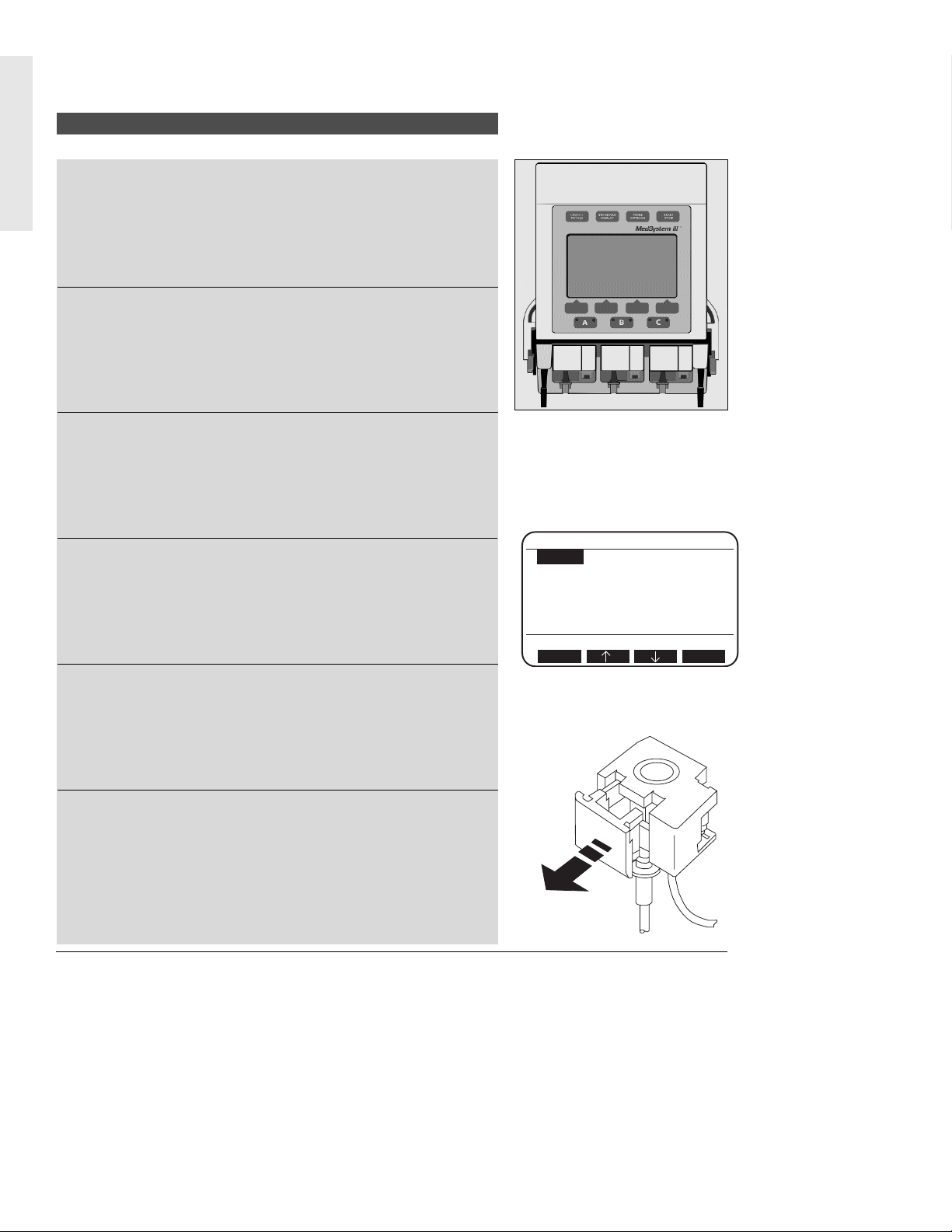
Free-flow Protection
The IVAC 28 and 25 Series Administration Sets contain a
cassette that provides protection from free-flow conditions. To
remove the cassette from the pump, the cassette’s slide clamp
is pulled to full extension, occluding the tubing and preventing
fluid from flowing.
Features
2
A: Stopped
DRUG? Wt ---- KG= 0.0 LB
A:Conc ------- mg/---- ml
A:Dose ------- mcg/kg/min
A:Rate ------- ml/h
A:VR 1 ml (Vol Rem)
A:VI 0 ml DI 0.0 mg
Press Select to choose line
Select
Clear
Page 5
INTRODUCTION
Monitoring System
The instrument continuously monitors pump conditions and
alerts with adjustable audio tones and visual messages.
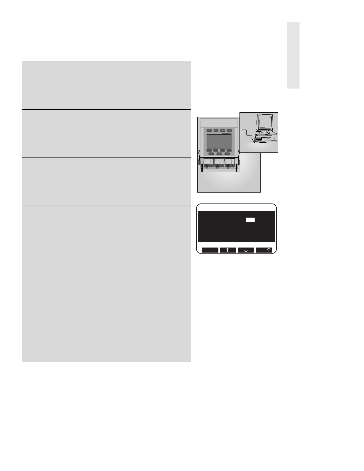
Data Monitoring
The pump can be configured to communicate with a remote
computer, such as a centralized patient monitoring nurses
station. The COMM receptacle is compatible with RS-232
cabling. A communications manual that describes the
programming and hardware involved is available.
Field Maintenance Software (FMS)
The pump can be modified to accommodate specialized clinical
applications. The Device Type parameters, occlusion limit, and
air-in-line threshold can be reconfigured with the optional FMS
software.
Secondary Mode
Allows the user to program two different rates of infusion to
run sequentially.
Full Range of Delivery Rates
Rates from 0.1 to 999 milliliters an hour.
Battery Capacity
A fully-charged battery provides 6 to 8 hours of operating time
with rates at 125 ml/h per channel.
3
A: Infusing Secondary
A: Secondary Rate 100 ml/h
A: Sec VolRem (VR) 100 ml
A: Sec Time(TR) 1 hr
A: Sec VolInf(VI) 1 ml
since 12:37p 01 Feb 02
Stop Affects Secondary
Select
Fast
Page 6
INTRODUCTION
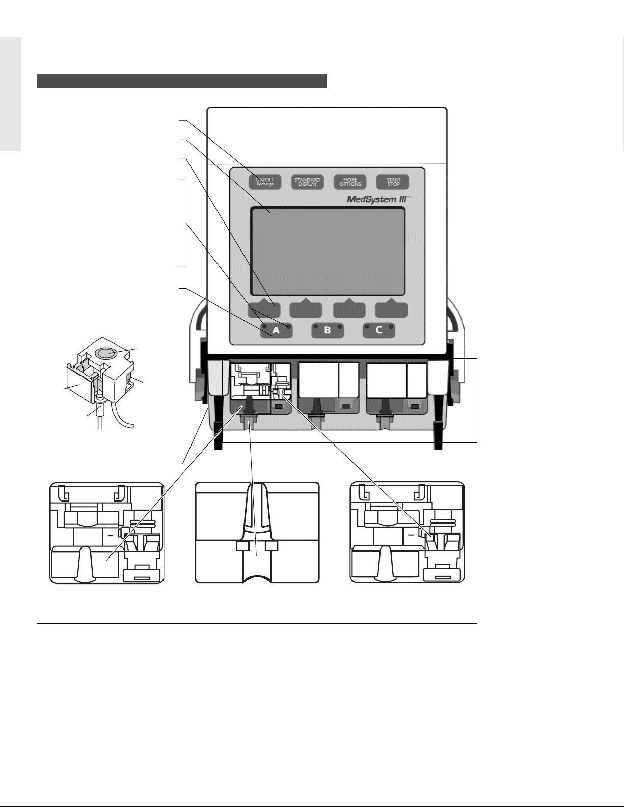
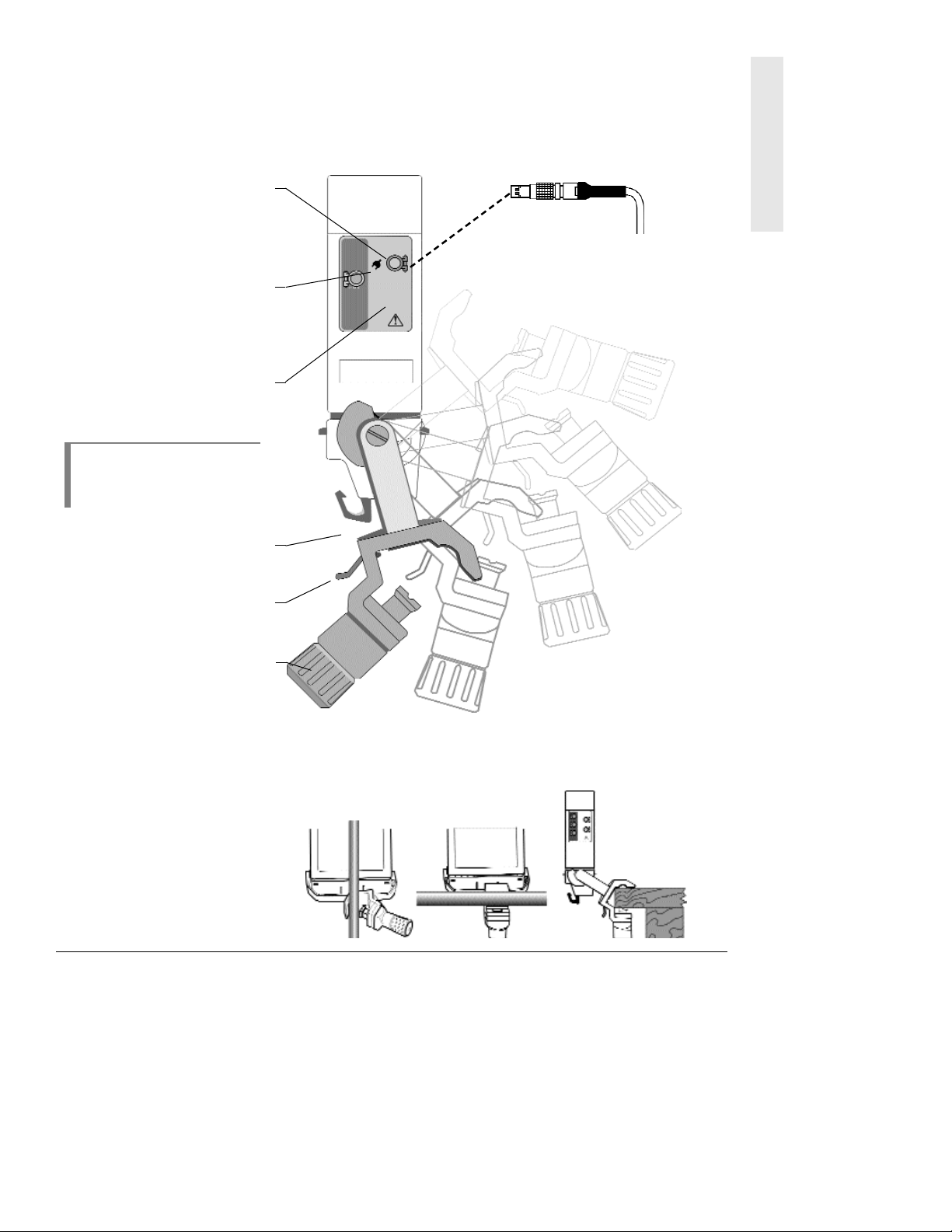
System Components
Slide
Clamp
Pressure
Dome
Piston
Tubing
Collar
Lower Assembly
3 Cassette Holders
Pump Latch Mechanism
Drives the cassette piston to move
fluid through the tubing.
Air-in-Line Sensor
Detects bubbles of air during
infusion.
Tubing Collar Recess
Holds tubing collar in place.
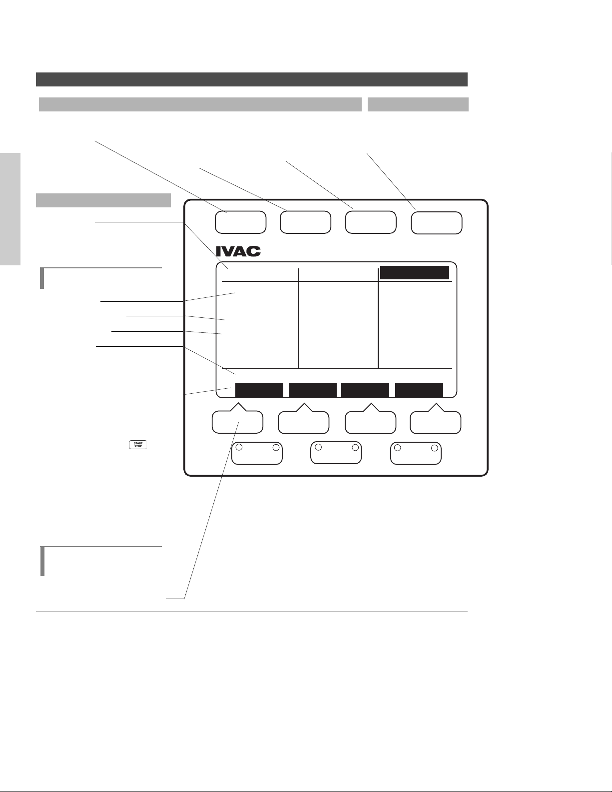
Front Panel
Instrument Keys
Display Screen
Softkey Pads
Channel Indicator Lights
Green:
• Steady - infusing on AC
power
• Flashing - infusing on
battery power
Red:
• Slow flashing - Advisory
• Rapid flashing - Alert
Channel Select Keys
Cassette
Portion of administration set,
inserts into cassette holder.
4
Page 7
INTRODUCTION
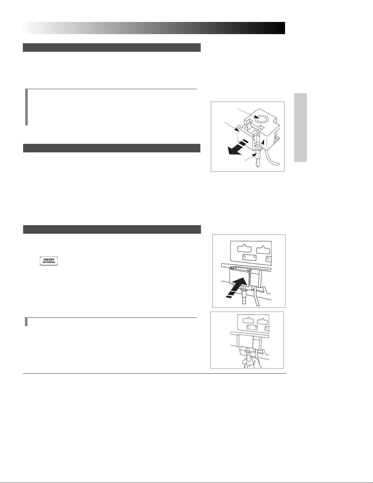
AC Adapter Power Cord
120V/60 Hz three-pronged
grounded adapter with 4 pin
locking connector, standard on
Model 2863.
Connector Panel
External Power
External power receptacle connects with power cord.
Plug Symbol
Green light on indicates AC
power is connected; batteries are
charging.
COMM
Communications line receptacle
connects with RS-232.
NOT E:
When inserting or
removing connectors to the
receptacles, avoid excessive
force or twisting.
Container Hook
One hook on each side of the
instrument.
Rotating Latch
Allows clamp to spin 360° and
position at every 90°.
Adjustable Pole Clamp
Jaw with clutch feature, mounts
pump to a pole or bedside.
Attaching Pole Clamp
To attach the pole clamp,
position the clamp jaw over the
mounting surface and turn the
knob until the clamp is tightened
and the pump feels secure.
When the knob is as tight as
possible, continued turning will
make it click and spin freely
without over-tightening.
5
Page 8

INTRODUCTION
To avoid possible injury to the patient, observe the following
precautions:
Epidural Administration
The MedSystem III pump can be used for epidural administration of
anesthetic and analgesic drugs. This application is only appropriate
when using anesthetic and analgesic drugs labeled for continuous
epidural administration and catheters intended specifically for
epidural use. Use only an IVAC 28 or 25 series set
wwiitthhoouutt
a ‘Y’
connector or injection port, for epidural infusions. The pump‘s
secondary mode must
nnoott
be used when the pump is being used for
epidural administration of anesthetic and analgesic drugs.
- Epidural administration of anesthetic drugs — Use indwelling
catheters specifically indicated for short-term (96 hours or less)
anesthetic epidural drug delivery.
- Epidural administration of analgesic drugs — Use indwelling
catheters specifically indicated for either short-term or long-term
analgesic epidural drug delivery.
Administration Sets
• Use only IVAC 28 and 25 Series Administration Sets. The use
of other sets will cause improper pump operation.
• Do not use the set if damaged.
• Do not insert a cassette into a channel with a Service status.
• Remove any cassettes from channel(s) requiring service.
• Ensure the cassette is properly installed before starting
infusions.
Electromagnetic and Radio Frequencies
Operating the pump near equipment which radiates high-energy
electromagnetic and radio frequencies (electrosurgical/cauterizing
equipment, portable radios, cellular telephones, etc.) may cause false
alarm conditions. If this happens, reposition the pump away from the
source of interference; or turn off the pump and manually regulate
the flow with the administration set regulating clamp.
Operational Precautions
Patient Precautions
WARNING:Epidural
administration of drugs other than
those indicated for epidural use
could result in serious injury to the
patient.
WARNING: It is strongly
recommended that the infusion
pump source container and
administration set used for epidural
drug delivery be clearly
differentiated from those used for
other types of administration.
6
Page 9

INTRODUCTION
Artifacts
It is normal for intravenous infusion devices to produce nonhazardous currents when infusing electrolytes. These currents vary at
a rate proportional to the infusion device flow rate. When the ECG
monitoring system is not functioning under optimal conditions, these
currents may appear as artifacts, simulating actual ECG readings. To
determine if ECG abnormalities are caused by patient condition or the
ECG equipment, place the infusion device on hold. If the ECG
readings become normal, the ECG equipment requires attention.
Proper setup of the ECG equipment should eliminate these artifacts.
Reference the appropriate ECG monitoring system documentation for
instructions on setup and maintenance.
Dropping/Jarring
If a pump is dropped or severely jarred, it should be immediately
taken out of service and inspected by qualified service personnel to
ensure proper function prior to reuse.
To ensure proper performance of the pump and to reduce potential
injury to the operator, observe the following precautions:
• The power cord must be connected to a properly grounded,
3-wire receptacle (“Hospital Use” or “Hospital Grade”)
• Avoid excessive force or twisting of detachable power cords,
when inserting or removing connector terminals.
• Use power cord indoors only.
• Disconnect AC and battery power when performing
maintenance.
• Do not use the pump in the presence of flammable
anesthetics.
• Do not open the instrument case. The case should only be
opened by qualified service personnel using proper
grounding techniques.
• Do not stack instruments on top of each other.
User Precautions
WARNING: When the
case is opened, an electrical shock
hazard exists which can result in
serious injury to persons and
instrument component damage.
7
Page 10

THERE IS
NO
PRINTING
ON THIS
PAGE
Page 11
BASIC OPERATION
9
BASIC OPERATION
Prepare solution container in accordance with the manufacturers’
instructions.
• A syringe can be used as the container for the IV fluid to be
infused. Syringe sizes from 20cc to 60cc of the B-D and Monoject
®
brands can be used.
NOTE:
The IVAC Model 8631A Syringe Holder is available as an
accessory that provides a convenient place to hold syringes while they
are being used as containers for IV fluid. The Syringe Holder is designed
to be easily installed and removed from the top of the pump and to
support up to three syringes. Do not use the Syringe Holder as a handle
to carry the pump.
Connect the container to the IV set.
Prime the IVAC 28 or 25 Series administration set in accordance with
Administration Set Directions for Use.
It is important to prime the set properly to eliminate air bubbles.
Ensure the cassette slide clamp is pushed in completely so tubing is not
occluded.
Invert the cassette so tubing is up. Slowly open the regulating clamp
and establish fluid flow to fully prime the set. Gently tap the cassette
and ‘Y’ sites as necessary to remove all air. Gently massage the pressure
dome to ensure no air bubbles are trapped.
Close regulating clamp before inserting and removing the cassette to
reduce the risk of free flow.
Press to turn pump on.
With tubing down, use a 45 degree, upward motion to insert cassette
into channel.
Push on clear portion of cassette until completely seated. Then push in
slide clamp flush with entire cassette.
Pull down gently on tubing collar. Press with thumb to seat tubing
collar in recess beneath cassette.
NOTE: Three beeps sound when inserted properly.
Preparing the Infusion
Loading the Set
Preparing the Administration Set
WARNING: An open
regulating clamp and slide
clamp can cause a freeflow condition and may
result in serious injury to
the patient.
Pressure Dome
Slide
Clamp
Tubing Collar
Clear portion of cassette
A
A
A
Page 12
10
BASIC OPERATION
Status Line
Displays infusion status
(Infusing; Stopped; Standby;
KVO; ALARM; FAULT; SERVICE)
for each channel.
NOTE:
S
tatus line in selected
channel is highlighted.
Infusion Rate
Volume Remaining
Volume Infused
Prompt Line
Displays messages that prompt
the user to make programming
choices and/or take appropriate
actions.
Softkeys Prompts
Displays function of specific
softkey.
STNDBY – Appears in softkey
information line
when
is
pressed during
infusion.
Cntrst – (Contrast) Brightens
or dims display.
GP II – When pressed, indi-
cates full name of
selected Device
Type on the
prompt line.
NOT E:
Additional softkey
prompts are displayed by
pressing More Options.
Softkey Pads (4)
Front Panel Overview
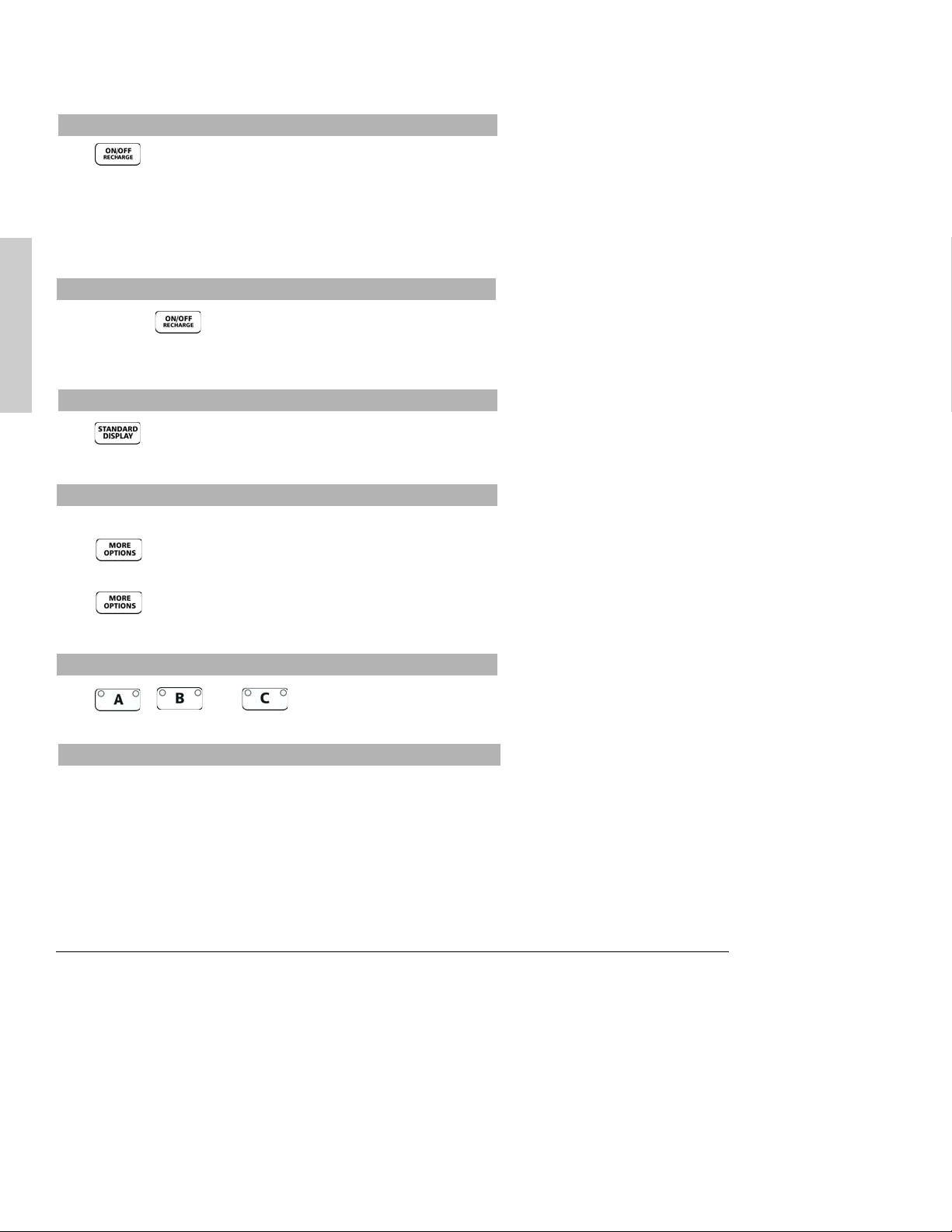
Instrument Control Keys
ON/OFF Recharge Key
Turns the pump on and
off.
STANDARD DISPLAY Key
Allows the user to
display Standard Display
page to view infusion
settings for all channels.
MORE OPTIONS Key
Allows the user to
display additional softkey
functions.
START/STOP Key
Starts or stops infusion
on selected channel.
Channel Control Key
Standard Display Page
ON/OFF
STANDARD
DISPLAY
MORE
OPTIONS
START
STOP
Stopped
125
VR: 996.2
VI: 12.8
Start affects channel C
STNDBY Cntrst GP
®
ml/h
MedSystem III® DLE
Standby
25
ml/h
VR: 138.8
VI: 26.9
A
B
Standby
95
ml/h
VR: 93.2
VI: 16.8
C
Page 13
BASIC OPERATION
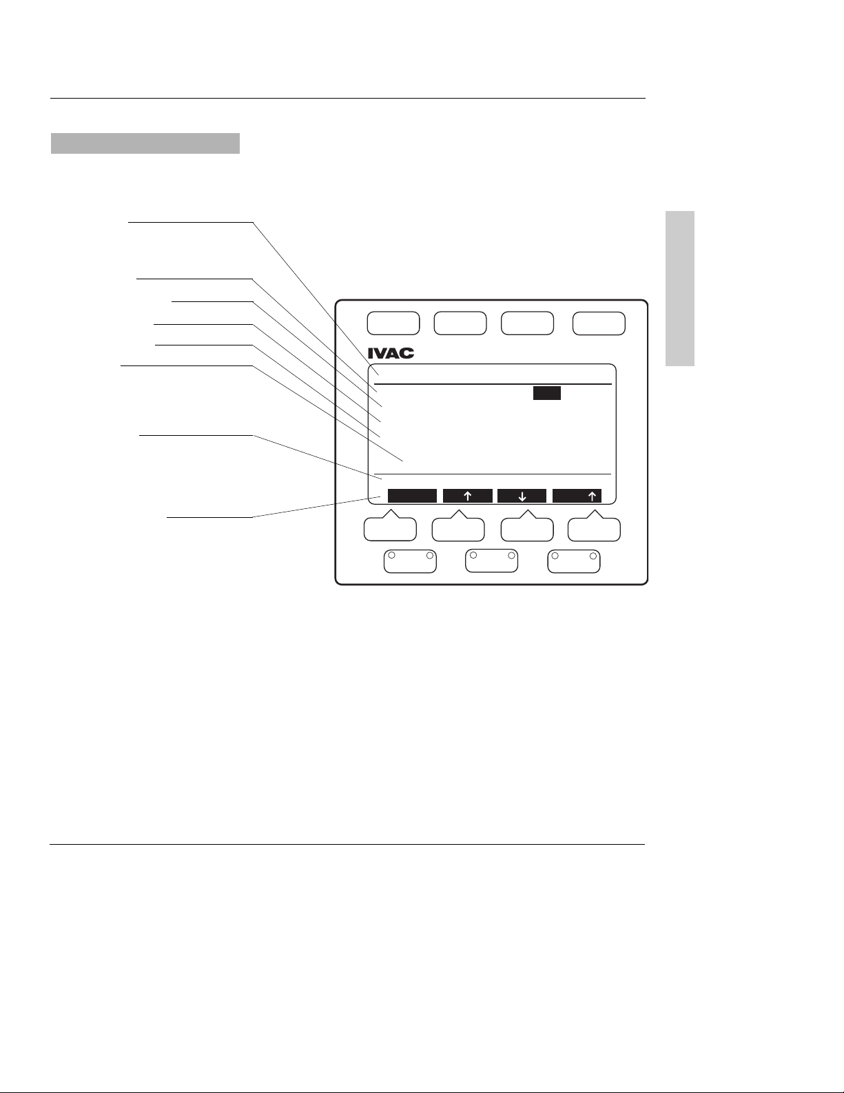
11
Selected channel is indicated by
the letter displayed at the
beginning of the first five lines.
Status Line
Displays infusion status for selected channel.
Infusion Rate
Volume Remaining
Time Remaining
Volume Infused
Date/Time
Displays when volume infused
was last cleared and infusion
began.
Prompt Line
Displays messages that prompt
the user to make programming
choices and/or take appropriate
action.
Soft Key Prompts
Displays function of specific
softkey.
Select – Moves highlight bar
through the
programmable
infusion
parameters.
↑↑
– Increases highlighted value.
↓↓
– Decreases highlighted value.
Fast
↑↑
– Increases highlighted
value at greater
increments.
Fast
↓↓
– Decreases highlighted
value at greater
increments.
Programming Page
ON/OFF
®
STANDARD
DISPLAY
MORE
OPTIONS
MedSystem III® DLE
A: Stopped
A: Primary Rate 25 ml/h
A: Pri VolRem (VR) 250 ml
A: Pri Time(TR) 10h 00m
A: Pri VolInf (VI) 10 ml
since 12:37p 01 Feb 02
Press Select to choose line
Select Fast
A
B
C
START
STOP
Page 14
12
BASIC OPERATION
Press .
• Instrument information page is momentarily displayed.
• Continuing to hold down ON/OFF key will keep the information
on the display.
• When the ON/OFF key is released, the Standard Display page is
displayed.
Press and hold .
• Display disappears.
• Pump is turned off.
Press .
• Standard Display page is displayed.
With the Standard Display page displayed:
Press
,
once.
•
TotVol, Device, Config, and Note softkeys appear.
Press again.
•
Batlog and DemoWd softkeys appear.
Press , , or .
• Selected channel programming page is displayed.
With programming page displayed:
Press
Select to choose value to change.
• Value is highlighted.
Scroll through values using
↑↑
, ↓↓, FAST↑↑, or FAST↓↓.
•
↑↑
and FAST↑↑increases highlighted values in single or multiple
increments.
To turn pump on
To activate additional Standard Display softkey prompts
To turn pump off
To view infusion settings for all active channels
To select channel and display Programming Pages
To program infusion
Page 15

BASIC OPERATION
13
• ↓↓and FAST↓↓decreases highlighted values in single or multiple
increments.
• Pressing
↑↑
or ↓↓changes direction of the FAST↑↑or FAST
↓↓
• Highlight remains flashing until Enter is pressed. If Enter is not
pressed, the entry incomplete advisory will sound.
Press
Enter to accept new value.
• Highlight moves to next programmable value if channel status is
Stopped or Standby.
• If status is
Infusing, highlight remains on selected value.
To recall a previous value after a new value is introduced but not
entered, press .
• Recall soft key appears.
Press
Recall.
• Number returns to previous value.
Press .
• Infusion starts or stops immediately, unless the channel’s
programming is incomplete, or if an advisory, alarm, or fault
condition exists on selected channel.
•
ALARM is displayed in affected channel status line.
• Alarm condition is displayed on the Standard Display of the
affected channel.
Press affected channel , , or .
• Alarm Information page is displayed for that channel.
With the programming page displayed:
Press .
Press
2°Sec to access Secondary page.
Press
CalcOn to access Dose Rate Calculation page.
Press .
Press
CalcOff to discontinue use of the Dose Rate Calculator.
To access alarm information
To activate additional Programming Page softkeys
See the TROUBLESHOOTING section
of this manual for more alarm
information.
See the ADVANCED OPERATION
section of this manual for
information on the use of the Dose
Rate Calculator function.
Page 16

14
BASIC OPERATION
Press , , or .
• Programming Page is displayed.
• Rate is highlighted.
Press
Select if current rate is desired
OR
Press
↑↑
, ↓↓, FAST↑↑, or FAST
↓↓
to change Rate.
• Value flashes.
Press
Enterto confirm.
• Highlight moves to volume remaining (VR)
Press
Select if current VR is desired
OR
Press
↑↑
, ↓↓, FAST↑↑, or FAST
↓↓
to change VR.
• Value flashes.
Press
Enter to confirm.
• Primary time remaining (TR) is calculated automatically, based on
VR and Rate.
• Highlight moves to volume infused (VI).
Press
Select if current VI is desired
OR
Press
Clear to reset volume infused to zero.
• Date and time are cleared.
•
Clear softkey switches to Recall.
Pressing
Recall softkey recalls previous VI value.
Press
Enter to confirm.
THEN
Open regulating clamp on administration set.
Press to begin infusion.
• Channel starts infusing.
• Current date and time are entered.
• Green infusion light on channel key stays lit.
• Display reverts to Standard Display page after one minute.
Verify solution flow.
Press .
Verify settings.
Programming Primary Infusion
To set primary rate
To set primary volume remaining (VR)
To clear primary volume infused (VI)
A: Stopped
A: Stopped
A: Primary Rate 100 ml/h
A: Primary Rate 100 ml/h
A: Pri VolRem (VR) 500 ml
A: Pri VolRem (VR) 500 ml
A: Pri Time(TR) 05h 00m
A: Pri Time(TR) 05h 00m
A: Pri VolInf(VI) 1 ml
A: Pri VolInf(VI) 1 ml
since 12:37p 01 Feb 02
Press Select to choose line
Select
A: Stopped
A: Primary Rate 100 ml/h
A: Pri VolRem (VR) 500 ml
A: Pri Time(TR) 05h 00m
A: Pri VolInf(VI) 1 ml
Press Select to choose line
Select
A: Stopped
A: Primary Rate 100 ml/h
A: Pri VolRem (VR) 500 ml
A: Pri Time(TR) 05h 00m
A: Pri VolInf(VI) 800 ml
Press Select to choose line
Select
A: Stopped
A: Primary Rate 100 ml/h
A: Pri VolRem (VR) 500 ml
A: Pri Time(TR) 05h 00m
A: Pri VolInf(VI) 0 ml
Press Enter or Recall
Enter
since 12:37p 01 Feb 02
Press Select to choose line
Select
since 12:37p 01 Feb 02
since 12:37p 01 Feb 02
since -----
Fast
Fast
Clear
Recall
Fast
Page 17

BASIC OPERATION
15
Press , , or .
• Programming Page is displayed.
• Rate is highlighted.
Press
↑↑
, ↓↓, FAST↑↑, or FAST
↓↓
to change Rate
• Value flashes.
Press
Enter to confirm.
• New rate begins infusing immediately.
Press , , or .
• Programming Page is displayed.
• Rate is highlighted.
Press
Select to highlight VR.
Press
↑↑
, ↓↓, FAST↑↑, or FAST
↓↓
to change VR.
• Value flashes.
Press
Enter to confirm.
• Infusion continues with new volume remaining.
Press , , or .
• Programming Page is displayed.
• Rate is highlighted.
Press
Select to highlight VI.
Press
Clear then Enter to reset volume infused to zero.
• Date and time are cleared.
•
Clear softkey switches to Recall.
Pressing
Recall softkey recalls previous VI value.
OR
Press
Enter to confirm.
• Infusion continues with volume infused reset to zero.
• Current date and time are entered.
Making Changes While Infusing
To titrate or change primary rate during infusion
To change volume remaining during infusion
To clear volume infused during infusion
NOTE: When the channel VI is
cleared, that volume is not
subtracted from the volume on
the TotVol page.
Page 18

16
BASIC OPERATION
Press .
• Standard Display page is displayed.
Press .
•
TotVol, Device, Config and Note softkeys appear.
Press
TotVol softkey.
• Total Volume page is displayed
• VI for each channel and total pump VI values are highlighted.
Press
ClrTotto reset volume infused to zero.
• Date and time are cleared.
Press
Enter to accept clearing of all values.
OR
Press
RECALL to return the previous Total VI .
Press appropriate channel , , or .
Press to stop infusion.
Press .
• Standard Display page is displayed.
Press
Stndby.
Press appropriate channel , , or .
Press to start infusion.
Press if Standard Display page not already displayed.
Press .
•
TotVol, Device, Config and Note softkeys appear.
Press
Config softkey.
• The first of five Instrument Settings pages is displayed.
Press
Select to move the highlight to Setup Line Option.
Press
↑↑
or ↓↓to choose Yes.
•
↑↑
and ↓↓will not be displayed if pump is infusing.
Press
Enter to enable programming option.
Press channel , , or .
To start an infusion from Standby status
To set up an infusion by Rate/Volume or Volume/Time
To place a channel on Standby during infusion
NOTE: When a channel is
Stopped for two minutes with a
cassette in place, a Channel Not
In Use advisory sounds. When a
channel is on Standby, the
advisory does not sound.
NOTE: Infusing channel should
always be stopped prior to
removing cassette.
Programming Option
To simultaneously clear Total Volume Infused for all channels
Stopped Stopped Stopped
TotVI A TotVI B TotVI C
Pri 20 Pri 20 Pri 20
Sec 0 Sec 0 Sec 0
= 20 = 20 = 20
Total VI = 60 ml
since 03:25p 10 Feb 02
Press ClrTot to clear TotVI
Stopped Stopped Stopped
TotVI A TotVI B TotVI C
Pri 0 Pri 0 Pri 0
Sec 0 Sec 0 Sec 0
= 0 = 0 = 0
Total VI = 0 ml
since -----
Press Enter or Recall
Enter
Stopped
100
ml/h
VR: 450
VI: 50
Start affects channel A
STNDBY Cntrst GP II
ClrTot
Recall
Instrument Settings (1 of 5)
* Audio Volume: highest
Sec Complete Advisory: No
Setup Line Option No
Time: am/pm 02:16p 01 Jul 02
Press Stnd Display to Exit
Select
NextPg
Page 19

BASIC OPERATION
17
With a channel infusing at KVO rate:
• Green light on channel key remains on.
• Red light on channel key flashes .
• Two toned advisory sounds.
Press appropriate channel , , or twice.
• VR is highlighted.
Press
REPEAT to recall previous VR.
OR
Press
↑↑
, ↓↓, FAST↑↑, and FAST↓↓to change VR.
• Value flashes.
Press
Enterto confirm.
Press to resume infusion and stop KVO rate.
NOTE: If current infusion rate is set below KVO rate, channel
will infuse at the lower rate.
To resume infusion when VR=0 (KVO)
KVO Status
Press if channel is infusing.
Press
Select to move highlight to
Setup:Select VR and Time.
OORR
Setup: Select VR and Rate
If highlighted choice is not desired, use arrow softkeys to change
setup choice.
• Choice flashes.
Press
Enter to accept .
• Highight moves to top of page.
NOTE: Rate will highlight but
cannot be changed if
Volume/Time option is active.
Time remaining selection will
highlight but cannot be changed
if Rate/Volume option active.
A: Stopped
A: Primary Rate 100 ml/h
A: Pri VolRem (VR) 500 ml
A: Pri Time(TR) 05h 00m
A: Pri VolInf(VI) 1 ml
since 02:16p 01 Jul 02
Setup: Select VR and Time
Press Select to choose line
Select
A: Stopped
A: Primary Rate 100 ml/h
A: Pri VolRem (VR) 500 ml
A: Pri Time(TR) 05h 00m
A: Pri VolInf(VI) 1 ml
since 02:16p 01 Jul 02
Setup: Select VR and Rate
Press Enter or Recall
Enter
Recall
KVO
100
Infusion
Complete
VR = 0
Alarm Info: Press A
Cntrst GP II
A: KVO 3.0 ml/h
A: Primary Rate 100 ml/h
A: Pri VolRem (VR) 0 ml
A: Pri Time (TR) ---A: Pri VolInf (VI) 100 ml
since 12:37p 01 Feb 02
Press Select to choose line
Select
REPEAT
Page 20

THERE IS
NO
PRINTING
ON THIS
PAGE
Page 21

ADVANCED OPERATION
19
ADVANCED OPERATION
This option allows two different rates of infusion to be administered
sequentially. When secondary volume remaining reaches zero, primary
infusion resumes automatically.
To avoid the possibility of sympathetic flow during secondary delivery
of intermittent medications, set up the administration set as
recommended below.
• Use a 16 gauge needle to attach secondary
set to primary upper ‘Y’ site, below a check
valve.
• Prepare the secondary IV container
according to your institution’s policy.
• Suspend secondary solution container at
least 8 inches above primary solution
container.
• Press , , or to
select channel.
WARNING: Setting a secondary rate over 275
ml/h may result in sympathetic flow with the primary
container.
Secondary Mode
Preparing the Administration Set and Container
8"
®
MORE
START
STANDARD
ON/OFF
OPTIONS
STOP
DISPLAY
®
®
DLE
BCA
Page 22

20
ADVANCED OPERATION
Press , , or .
• Primary programming page is displayed.
Press .
Press 2º Sec softkey.
• Secondary programming page is displayed.
Press Select to highlight secondary VR, if necessary.
Press REPEAT to enter the last VR selected.
OR
Press ↑↑,
↓↓
, Fast ↑↑or Fast
↓↓
to change VR.
• Value flashes.
Press Enter to confirm.
• Secondary time remaining (TR) is calculated automatically, based
on VR and Rate.
• Highlight moves to secondary volume infused (VI).
Press Select if current VI is desired
OR
Press Clear to reset volume infused to zero.
• Date and time are cleared.
• Clear softkey switches to Recall.
Pressing Recall softkey recalls previous VI value.
Press Enter to confirm.
Press Select if current rate is desired
OR
Press ↑↑,
↓↓
, Fast ↑↑or Fast
↓↓
to change Rate.
• Value flashes.
Press Enter to confirm.
THEN
Open regulating clamp on secondary administration set.
Press to begin infusion.
• Four tones sound if primary infusion is in progress.
• Pump starts infusing at secondary rate.
• Current date and time are entered.
Programming Secondary Infusion
To set secondary rate
To set secondary volume remaining(VR)
To clear secondary volume infused(VI)
NOTE: Secondary programming page
is reverse highlighted.
A: Infusing
A: Primary Rate 50 ml/h
A: Pri VolRem (VR) 450 ml
A: Pri Time(TR) 09h 00m
A: Pri VolInf(VI) 50 ml
since 12:37p 01 Feb 02
Press Select to choose line
2° Sec
A: Infusing
A: Secondary Rate 100 ml/h
A: Sec VolRem (VR) 0 ml
A: Sec Time(TR) -----
A: Sec VolInf(VI) 200 ml
since 12:37p 01 Feb 98
Stop Affects Secondary
Select
CalcOn
Repeat
Page 23

ADVANCED OPERATION
21
• Display reverts to Standard Display page after one minute.
Press .
Verify settings.
Verify solution flow from secondary container.
Press , , or .
• Secondary programming page is displayed.
• Rate is highlighted.
Press ↑↑,
↓↓
, Fast ↑↑or Fast
↓↓
to change rate.
• Value flashes.
Press Enter to confirm.
• New rate begins infusing immediately.
Press , , or .
• Secondary programming page is displayed.
Press .
• 1ººPri and CalcOn softkeys appear.
Press 1ººPri softkey.
• Primary programming page is displayed.
Press Select to highlight value(s) to change.
Press ↑↑,
↓↓
, Fast ↑↑or Fast
↓↓
to change value(s).
Press Enter to confirm.
Close regulating clamp on secondary infusion set.
Press , , or .
• Secondary programming page is displayed.
Press .
• 1ººPri and CalcOn softkeys appear.
Press 1ººPri softkey.
• Primary programming page is displayed.
Press to begin primary infusion and stop secondary infusion.
• Four tones will sound.
• Infusion starts at primary rate.
To titrate or change secondary rate during infusion
To review or change primary value(s) during secondary infusion
To start primary infusion before secondary completes
WARNING: Pressing
would result in the remaining
secondary medication being delivered
at the primary rate.
NOTE: Channel display on the
Standard Display is reverse
highlighted.
Infusing
Secondary
100
ml/h
VR = 91
VI = 9
Stop affects channel A
Cntrst GP II
Page 24

Press , , or .
• Primary programming page is displayed.
If infusing, press to stop infusion.
Press .
• 2
ºº
Sec and CalcOn softkeys appear.
Press CalcOn.
• Dose Rate Calculator programming page is displayed.
• Drug? is highlighted.
Scroll using arrow softkeys to display alphabetized, abbreviated,
generic drug names.
• ↓↓moves A to Z.
• ↑↑moves Z to A.
e.g. Dopamine___ mg/___ml and ___mcg/kg/min
Lidocaine___ Gm/ml and ___ mg/min
Press Enter when desired drug name is highlighted.
• Highlight moves to Wt.
Choose patient’s kilogram weight using the arrow softkeys.
Press Enter when desired weight is displayed.
• Highlight moves to Conc.
Choose
concentration
using the
arrow softkeys.
Press Enter when desired concentration is displayed.
• Highlight moves to value for diluent volume.
Choose
diluent volume
using the
arrow softkeys.
Press Enter when desired volume is displayed.
• VR is automatically set when the diluent volume value is
enteredbut can be changed if desired.
• Highlight moves to Dose.
22
ADVANCED OPERATION
With this feature, the instrument calculates a volumetric or dose rate
based on values entered for patient weight, drug concentration (drug
amount and diluent volume) and dosing parameters. If a dose is
entered, the volumetric rate is calculated. If a volumetric rate is
entered, the dose is calculated.
Dose Rate Calculator (DRC) Programming using a specific drug name
WARNING:
Ensure correct
entry of all drug calculation infusion
parameters. Consult the drug
manufacturer’s labeling for information
concerning appropriate administration
guidelines and
dosages.
Programming Drug
Programming Weight
Programming Concentration
NOTE
:
Pressing , ,or
at any time during DRC set-up,
returns the highlight to the top of
the page.
NOTE:
Dose Rate programming
page will not display if channel is
infusing. If infusing in secondary
mode, switch to primary mode
and stop infusion before
proceeding.
NOTE
: Changing drug name clears
previous values and changes drug
concentration and dose rate
parameters to parameters
appropriate for the selected drug.
A: Stopped
DRUG? Wt ---- KG= 0.0 LB
A:Conc ------- mg/---- ml
A:Dose ------- mcg/kg/min
A:Rate ------- ml/h
A:VR 1 ml (Vol Rem)
A:VI 0 ml DI 0.0 mg
Press Select to choose line
Select
Clear
A: Stopped
DOPAMINE Wt 70.0 KG=154.3LB
A:Conc 400 mg/ 250 ml
A:Dose 5.0 mcg/kg/min
A:Rate 13.1 ml/h
A:VR 250 ml (Vol Rem)
A:VI 0 ml DI 0.0 mg
Press Select to choose line
Select
Fast
Page 25

ADVANCED OPERATION
23
Programming Dose
NOTE: Calculated rates for infusion
are fractional and will be displayed
as a fraction on the Standard
Display even if Device Type is set
for whole numbers.
Choose
dose
using the
arrow softkeys.
Press Enter when desired dose is displayed.
• Volumetric rate is automatically calculated.
• Highlight moves to Rate.
Choose
rate value
using the
arrow softkeys if dose rate is not desired.
Press Enter when desired volumetric rate is displayed.
• When rate is changed, dose value is automatically calculated.
• Highlight moves to VR.
Change
VR value using the arrow softkeys.
Press Enter when desired VR is displayed.
• Highlight moves to VI.
Press Clear then Enter to reset volume infused to zero.
• Highlight moves to DI.
Press Clear then Enter to reset dose infused to zero.
Open regulating clamp.
Press to begin infusing.
• Channel starts infusion.
• Display switches to Standard Display page after 1 minute. DRC
parameters are displayed.
Verify fluid flow.
Press .
Verify settings.
Press , , or .
• Dose Rate Calculator programming page is displayed.
• Dose value is highlighted.
Press Select to scroll through values that can be changed.
When highlight is on value to be changed (Dose, Rate, VR, VI, DI), use
arrow softkeys until desired value is displayed
.
• When dose is changed, rate is automatically recalculated.
• When rate is changed, dose is automatically recalculated.
When highlight is on value for VI or DI, Clear softkey becomes active.
Pressing the Clear softkey changes the value to 0.0.
Press Enter after each value change to accept the new value.
• New rate begins infusing immediately.
Press .
• Verify settings.
Changing DRC values while infusing
Changing Volumetric Rate
Changing Volume Remaining
Clearing the Volume Infused(VI) and Dose Infused(DI)
NOTE: Stop infusion to make
changes to the drug name, weight,
or concentration.
Infusing
1
13
ml/h
5.0
mcg/k/mn
DOPAMINE
Stop affects channel A
Cntrst GP II
Page 26

24
ADVANCED OPERATION
Dose Rate Calculator Programming with DRUG?
NOTE:
Dose Rate programming
page will not display if channel is
infusing. If infusing in secondary
mode, switch to primary mode and
stop infusion before proceeding.
Programming Weight
Programming Concentration
Programming Dose
D
rug concentration
parameters
G
m, mg, mcg, mMol, mEq, mUn, and Un
Dose parameters
measure —
Gm, mg, mcg, Ng,
mMol, mEq, mUn, or Un
weight —
kg
time —
min, hr, or day
The Drug? selection can be used to calculate a drug not listed in the
pump or for an alternative dosing regimen.
Press , , or .
• Primary programming page is displayed.
Press if channel is infusing.
Press .
• 2º Sec and CalcOn softkeys appear.
Press CalcOn.
• Dose Rate Calculator programming page is displayed.
• Drug? is highlighted.
Press Select.
• Highlight moves to Wt.
Choose
patient’s KG weight using arrow softkeys.
Press Enter when desired weight is displayed.
• Highlight moves to Conc.
Choose
concentration using arrow softkeys.
Press Enter when desired concentration is displayed.
• Highlight moves to concentration parameters.
Choose
desired concentration parameters using arrow softkeys.
Press Enter when desired parameter is displayed.
• Highlight moves to value for diluent volume.
Choose
diluent volume value using arrow softkeys.
Press Enter when desired volume is displayed.
• VR is automatically set when the diluent volume is entered, but
can be changed if desired.
• Highlight moves to Dose parameters.
Choose dose parameters (measure/weight/time) using arrow softkeys.
Press Enter when each desired dose parameter is displayed.
• Highlight moves to next parameter each time Enter is pressed.
• Highlight moves to Dosewhen Enter is pressed to accept time
value.
Choose
dose using arrow softkeys.
Press Enter.
• Highlight moves to Rate parameters.
A: Stopped
DRUG? Wt ---- KG= 0.0 LB
A:Conc ------- mg/---- ml
A:Dose ------- mcg/kg/min
A:Rate ------- ml/h
A:VR 1 ml (Vol Rem)
A:VI 0 ml DI 0.0 mg
Press Select to choose line
Select
Clear
Page 27

ADVANCED OPERATION
25
Choose
volumetric rate using arrow softkeys if dose calculation is not desired.
Press Enter when desired rate is displayed.
• When rate is changed, dose is automatically calculated.
• Highlight moves to VR.
Choose
VR value using the arrow softkeys.
Press Enter when desired VR is displayed.
• Highlight moves to VI.
Press Clearthen Enter to change VI value to 0.
• Highlight moves to DI.
Press Clear then Enter to change DI value to 0.
Open regulating clamp.
Press to begin infusion.
• Channel starts infusing.
• Display switches to Standard Display page after 1 minute. DRC
parameters are displayed.
Verify fluid flow.
Press .
Verify settings.
Press , , or .
• Dose Rate Calculator programming page is displayed.
Press to stop if infusing.
Press .
Press CalcOff.
• Display reverts to primary programming page.
• Volumetric rate, volume remaining and volume infused from DRC
is carried over to the primary programming page.
Discontinuing DRC option
Changing Volume Remaining
Clearing Volume Infused (VI) or Dose Infused (DI)
Facts about DRC
Changing Volumetric Rate
• Drug name, patient weight, or drug concentration
cannot be changed while infusing. Changes to patient
weight or concentration will recalculate volumetric rate
but maintain dose rate.
• All drug names are generic and abbreviated if the name
contains more than eight letters.
• Weight can only be entered in Kg’s but is displayed in
Kg’s
and
Lbs. Weight units can be switched to grams
by pressing
↓↓
to value of 1Kg then repress
↓↓
. A two
tone advisory sounds.
• If dose measurement parameters and concentration
measurement parameters are unrelated, a volumetric
rate will not calculate. Attempts to start will display a
prompt message:
Verify all dose settings.
• When a drug amount is 10,000 or greater, a Kis used
to replace 000th (i.e. 10,000=10K; 12,000 = 12K).
• If a recalculated dose results in a rate outside the rate
ranges, a prompt message is displayed:
Rate too
High,reenter value or Rate too Low,reenter value.
• If a recalculated rate results in a dose outside the dose
range, the channel will infuse at the entered rate but
the dose will display the minimum or maximum
allowable limit: (i.e. <0.1 or >999k).
• Secondary option cannot be used when the Dose Rate
Calculator is enabled.
• If instrument is off for more than five minutes, the DRC
mode will revert to the primary mode.
A: Stopped
DOPAMINE Wt 70.0 KG=154.3LB
A:Conc 400 mg/ 250 ml
A:Dose 5.0 mcg/kg/min
A:Rate 13.1 ml/h
A:VR 250 ml (Vol Rem)
A:VI 0 ml DI 0.0 mg
Press Select to choose line
CalcOff
Page 28

26
ADVANCED OPERATION
There are six Device Types with preset parameters that accommodate
specific clinical applications. They are:
General Purpose
Neonatal
Controller Pressure
When setting up the pump, select the device type that best suits your
clinical needs.
The abbreviated name of the Device Type appears as a
softkey on the Standard Display page. Pressing the softkey displays
the device type on the prompt line.
Maximum rate, maximum volume, pressure and air-in-line threshold
are configured at the factory. See Table 1 for a complete listing of
preset parameters. Refer to the config softkey section following Table 1
for programmable and configurable parameters. These parameters can
be modified to meet the institution’s specific requirements using the
optional FMS software.
Press .
Press .
• TotVol, Device, Config and Note softkeys appear.
Press Device softkey.
• The currently selected Device Type has an asterisk and is highlighted.
Press Select to move the highlight through the list.
Press Enter when the desired device is highlighted.
If preset values are compatible with the newly selected device type,
• An asterisk appears next to the device name.
If channel is not infusing when device type is changed and preset
values are not compatible with the newly selected device type,
• The display switches to a notification screen.
• Incompatible Channel(s) indicated.
• Choice is given to continue.
If Yes,
• Incompatible values are cleared.
• Display reverts to Standard Display Page.
• New Device Type becomes active.
If No,
• Display reverts to Change Device Type page.
Device
NOTE: The Device Type
programming selection affects all
three channels. It is not possible to
program different Device Types for
a channel independently.
To change Device Type
Operating Room
General Purpose II
Operating Room II
Stopped
100
ml/h
VR: 450
VI: 50
Device: General Purpose II
STNDBY
Cntrst
GP II
Infusing
100
ml/h
VR: 450
VI: 50
Stop affects channel A
TotVol Device Config Note
Change Device Type
General Purpose
Neonatal
Controller Pressure
Operating Room
* General Purpose II
Operating Room II
Press Stnd Display to Exit
Select
Enter
Page 29

ADVANCED OPERATION
27
If channel is infusing when device type is changed and preset values
are not compatible with the newly selected device type,
• The display switches to the notification screen.
• Incompatible Channel(s) is indicated.
• Choice is given to continue.
If No,
• Display reverts to Change Device Type page for user to select
another device type.
If Yes,
• The pump will alarm.
• Infusion will stop on affected channel.
• Display reverts to Standard Display with Alarm indicated in
affected channel.
Press affected channel , , or
.
Follow instructions displayed.
Table 1
Occlusion
Detection
Method
Occlusion Alarm
Setting
Maximum
Pressure
Air-in-line Alarm
Threshold
KVO Rate*
Rate Range
Maximum VR
Setting
Pump Not In
Use Advisory
ALL Setting
for VR
Baseline
Baseline 5 psi
15 psi
500 µl
3 ml/h
1 —999 ml/h
9999 ml
Yes
N/A
Baseline
Baseline+3 psi
15 psi
50 µl
1.0 ml/h
0.1—99.9 ml/h
9999 ml
Yes
N/A
Absolute
Threshold
Absolute
3 ft H2O
3 ft H2O
500 µl
3 ml/h
1 — 299 ml/h
9999 ml
Yes
N/A
Baseline
Baseline+5 psi
15 psi
500 µl
3 ml/h
1 —999 ml/h
9999 ml
No
Option
Baseline
Baseline+5 psi
15 psi
500 µl
3.0 ml/h
0.1—999 ml/h
9999 ml
Yes
N/A
Baseline
Baseline+5 psi
15 psi
500 µl
3.0 ml/h
0.1—999 ml/h
9999 ml
No
Option
Default General
Neonatal
Controller Operating General Operating
Parameter Purpose Pressure Room Purpose II Room II
* Channel will infuse at the KVO rate shown in table or at the current infusion rate,
whichever is lower.
NOTE: Values shown in table can
be modified to meet the
institution’s requirements using
optional FMS software. To review
actual default parameters on a
MedSystem III pump, select a
Device Type and refer to
Instrument Settings pages 2
through 5. An asterisk appears
beside settings which are not
factory default.
ALARM
-----
Rate/Vol
Settings
Cleared
Alarm Info: Press channel A
CANCEL QUIET
Page 30

28
ADVANCED OPERATION
Config
(Configuration)
The Config option allows the user to view and/or change some
instrument settings. There are five pages in this option. Items shown
on page 1 can be changed by user (see Table 2). Pages 2 - 5 can only
be changed by qualified personnel using the optional FMS software .
Press .
Press .
• TotVol, Device, Config and Note softkeys appear.
Press Config softkey.
• The first of five Instrument Settings pages is displayed.
• An asterisk indicates options that have been changed from
factory settings.
Pressing Select moves the highlight through the list .
Press ↑↑and ↓↓to change a highlighted setting.
• Select softkey changes to Enter and NextPg softkey changes
to Recall when a setting is changed.
Press Enter to accept new setting
OR
Press Recall to recall previous setting.
Press to exit Instrument Settings page.
T
able 2
Option Choices Description
Audio Volume: low
medium
high
highest
Sec Complete Advisory: Yes
No
Setup Line Option: No
Yes
Time: 24 hr
am/pm
Hour/minutes
00:00-23:59
Day 1-31
Month Jan-Dec
Years
00-99
To access Instrument Settings information
A tone accompanies each level to aid in
determining volume choice. If an alarm is
ignored, the volume will ramp to the
highest audio unless disabled by FMS.
Pump sounds two tones and displays
advisory when secondary VR = 0.
Enables infusion to be set up as
rate/volume or volume/time. Stop infusion
before modifying this line option.
Allows pump to be set with a 12 or 24
hour clock.
}
Each item can be adjusted when
highlighted
Infusing
100
ml/h
VR: 450
VI: 50
Stop affects channel A
TotVol Device Config Note
Instrument Settings ( 1 of 5 )
*Audio Volume: low
*Sec Complete Advisory: Yes
Setup Line Option: No
Time: am/pm 9:56a 01 Feb 02
Press Stnd Display to Exit
Select
NextPg
Page 31

ADVANCED OPERATION
29
The Note soft key accesses the Special Note Message page. When
note is programmed, it appears when the pump is turned on.
Press .
Press .
• TotVol, Device, Config and Note softkeys appear.
Press Note softkey.
• Note information is displayed.
• If no information has been programmed on the note page, there
will be a two tone advisory and the message There is no Special
Note will display on the prompt line.
The BatLog softkey accesses the Battery History Log page. This page is
provided for the Biomedical Engineering staff to review and record
battery history data.
Press .
Press twice.
• BatLog and DemoWD softkeys appear.
Press BatLog softkey.
• The Battery History page is displayed.
Display switches to Standard Display page after 1 minute
OR
Press to exit Battery History page.
NNoottee
BBaattLLoogg
(Battery History Log)
To access Note(s)
To access Battery History Log
Infusing
100
ml/h
VR: 450
VI: 50
Stop affects channel A
TotVol Device Config Note
Infusing
100
ml/h
VR: 450
VI: 50
There is no Special Note
TotVol Device Config Note
Infusing
100
ml/h
VR: 450
VI: 50
Stop affects channel A
BatLog DemoWD
Page 32

THERE IS
NO
PRINTING
ON THIS
PAGE
Page 33

NOTE: Channel’s VR and VI calculations are updated with each press
of ClrAir softkey.
NOTE: A appears on S tandard Display page to indicate CONFIRM has
been pressed.
TROUBLESHOOTING
31
Use this troubleshooting information in conjunction with appropriate
hospital procedures.
Press
QUIET.
• Audio tone stops.
• Red light flashes on affected channel.
Press affected channel , , or
• Alarm Information page is displayed.
Take appropriate action(s) indicated on the display.
Press to resume infusion.
silences Advisories, Alarms, and Faults for two
minutes. Softkey is accessible during alarm status.
clears alarm and advisory messages and stops
tone. Use when alarm or advisory condition cannot
be corrected or user chooses not to correct.
moves air bubbles past air-in-line sensor. Each
press of the ClrAir softkey displaces 0.2 ml of air
and fluid. Three beeps indicate when air bubble is
no longer in front of the air-in-line sensor.
is present during Check Fluid Side alarms. Allows
infusion tocontinue if no upstream occlusion is
found and fluid is flowing in drip chamber.
resets resumable fault conditions. Used when
attempting to re-establish normal operation of a
channel.
disables use of affected channel. Servicing of the
pump is required before channel can be used.
SERVICE
RETRY
CONFIRM
ClrAir
CANCEL
QUIET
To respond to an advisory, alarm, or fault message
Alarm Response Keys
TROUBLESHOOTING
Page 34

32
TROUBLESHOOTING
Check Air Sensor
At installation of cassette:
a) air is detected in tubing;
b) tubing collar is not prop-
erly seated;
OR
c) air sensor is dirty or
damaged.
• Verify tubing collar is fully seated in air sensor recess.
• Verify tubing in air sensor recess is not damaged, twisted or dirty.
• Press ClrAir on channel's Alarm Information page. Three beeps
indicate air bubble is no longer in front of air sensor.
• If air is still present, remove cassette and manually clear air
according to hospital policy.
• If no air is present, clean air sensor recess as directed in cleaning
instructions.
Infusion Complete VR=0
VR has counted down to
zero. Channel is infusing at
KVO rate.
• Enter new VR or, if same volume is desired, press REPEAT.
• Press Enter.
• Press to resume primary infusion rate.
Low Battery
30 minutes or less battery
power remaining.
• Connect AC adapter power cord to pump.
• Plug into wall outlet.
Channel Not In Use
Two minutes have elapsed
since cassette was
installed or infusion was
stopped.
• Remove cassette,
OR
• Press to start infusion,
OR
• Press
STNDBY to place channel on Standby.
T wo beeps, slow flashing red light
on infusing channel’s channel key;
infusion continues.
CORRECTIVE ACTION
Advisories
Page 35

TROUBLESHOOTING
33
Air In Line
Air detected in fluid pathway during infusion, or air
sensor is dirty.
• Verify tubing collar is fully seated in air sensor recess.
• Verify tubing in air sensor recess is not damaged, twisted or dirty.
• Press ClrAir softkey on channel's Alarm Information page. Three
beeps indicate air bubble is no longer in front of air sensor.
NOTE: Each press of the ClrAir softkey displaces 0.2 ml of air and
fluid and updates channel’s VR and VI calculations.
• If air is still present, remove cassette and manually clear air
according to hospital policy.
• If no significant air is present, clean air sensor recess as directed
in cleaning instructions.
• Set up pump at, or slightly below, IV site to minimize formation
of micro bubbles.
• Press to resume infusion.
Air In Lower Tubing
Air bubbles detected in fluid
pathway with a total volume
exceeding the air in line
threshold setting.
Possible outgassing and/or
leaks in administration set.
• Check administration set for leaks.
• Check lower tubing for multiple small air bubbles.
• Press ClrAir softkey on channel's Alarm Information page. Three
beeps indicate air bubble is no longer in front of air sensor.
NOTE: Each press of the ClrAir softkey displaces 0.2 ml of air and
fluid and updates channel’s VR and VI calculations.
• If air is present, clear air according to hospital policy.
• Set up pump at or slightly below, IV site to minimize formation
of micro bubbles.
• If no significant air is present, press to resume infusion.
Battery Depleted
Insufficient battery power.
The pump will shut down in
5 minutes.
• Connect AC adapter power cord to pump and plug into wall outlet.
• Press to resume infusion(s).
CORRECTIVE ACTION
Four rapid-beeps, infusion stops,
rapidly flashing red light on
channel key .
Alarms
Page 36

• Check tubing between container and pump for a closed regulating
clamp, closed vent (with unvented container), kinked tubing,
empty syringe, or any restriction to flow.
• If NO occlusion is present, press CONFIRM.
• Press to resume infusion.
• Verify fluid is flowing in drip chamber.
• A appears on standard display to indicate Confirm has been
pressed.
34
TROUBLESHOOTING
Cassette Not Latched
Cassette is partially
disengaged or latching
mechanism is dirty.
ALARMS (continued)
Four rapid-beeps audio,
rapid-flashing red light and
infusion stops.
• Push cassette completely in. Ensure slide clamp is flush with
entire cassette. Press to resume infusion.
• If condition continues, try cassette in a different channel. Replace
administration set if alarm recurs.
• Clean lower assembly according to Cleaning Instruction described
in MAINTENANCE section of this document.
Cassette Removed
Cassette is removed from
holder while channel is
infusing.
• Reinstall cassette, and press to resume infusion.
OR
• Press CANCEL.
Check Fluid Side
Possible upstream restrictions to flow.
Cassette Jammed
Cassette piston is difficult
to move or piston sleeve is
loose.
• Remove cassette, check placement of soft, plastic piston sleeve
and reposition, if necessary.
• If condition continues, try cassette in a different channel.
• Replace administration set if alarm recurs or if piston does not
move freely.
• If Alarm recurs with several cassettes, channel may need service.
CORRECTIVE ACTION
INCORRECT
CORRECT
Page 37

TROUBLESHOOTING
35
Faulty Cassette
Cassette may be damaged
or inoperable.
Possible disfunction of
cassette sensor located in
holder.
• Reinsert cassette in another channel.
• If alarm recurs in second channel, replace administration set.
• If alarm recurs with two cassettes in the same channel, press
SERVICE and contact qualified service personnel.
Fluid-Side Occluded
Upstream restriction to
flow.
• Check tubing between container and pump for a closed regulating
clamp, closed vent (with unvented container), kinked tubing,
empty syringe, or any restriction to flow.
• Clear occlusion.
• Press to resume infusion.
Patient-Side Occluded
Downstream restriction to
flow.
• Check tubing between pump and patient for kinks, closed clamps,
closed stopcocks, clogged filters, site problems, etc.
• Clear occlusion or change infusion site.
• Press to resume infusion.
Pumping Latch Closed
Pumping latch jaw located
to right of air sensor is
closed or broken.
ALARMS (continued)
Four rapid-beeps audio,
rapid-flashing red light and
infusion stops.
INCORRECT
Rate/V ol Settings Cleared
Rates and/or volumes are
incompatible with newly
selected Device Type.
• Re-enter settings as required.
• Press to resume infusion.
CORRECTIVE ACTION
CORRECT
CORRECTIVE ACTION
CORRECT
Air Sensor
Pumping
Latch Jaw
• Using only your finger, push down pumping latch jaw until it snaps
open.
• If pumping latch jaw is visibly broken, press SERVICE and contact qualified service personnel.
CAUTION:
Never use a blunt instrument to open a closed pumping latch.
INCORRECT
Page 38

36
TROUBLESHOOTING
Screen is too light or dark
to read, with pump on.
• Press
• Press Cntrst softkey to change screen contrast.
Pump Shut Off: Low Power
Pump had shut down after
a Battery Depleted alarm
had not been corrected.
• If power cord has been detached from pump, reconnect terminal
end to pump’s EXTERNAL POWER receptacle.
• Plug AC adapter power cord into electrical outlet.
• next to EXTERNAL POWER receptacle is lit green when
power cord is properly attached.
Channel Out of Order
Safety checks built into
software have detected a
faulty channel.
Fault Number
Safety checks built into
software have detected a
fault condition.
Numeric message, Europeansiren, rapid-flashing red light, infusion stops.
CORRECTIVE ACTION for resumable faults, only.
• Press affected channel , , or
• Follow instructions on channel's Alarm Information page.
• Press RETRY to clear Fault.
• If Fault recurs, press SERVICE and contact qualified service
personnel.
Blank screen, continuous-tone red
and green lights continuous, all
infusions stop.
Blank Screen
Safety checks built into
software have detected an
instrument error condition.
Attempt to reset pump:
• Turn pump off, then on again.
• Press to resume each channel that had been infusing.
• If Watchdog alarm recurs or pump cannot be turned on, replace
pump and notify qualified service personnel.
CORRECTIVE ACTION
CORRECTIVE ACTION
CORRECTIVE ACTION
Fault
Watchdog
Other Conditions
Page 39

MAINTENANCE
Specifications
STANDARDS UL 544
CSA C22.2, No. 125
CASE MATERIAL Impact resistant polycarbonate/ABS alloy
DIMENSIONS Height 7.875 inches (20.00 centimeters)
Width 6 inches (15.24 centimeters)
Depth 2.10 inches (5.33 centimeters)
WEIGHT Approximately 5.1 pounds (2.32 kilograms) includes Pole Clamp.
AIR-IN-LINE (
OCCLUSION PRESSURE (
DEFAULT) 500 µl except for Neonatal which is 50µl
DEFAULT) 15 psi except for Controller pressure device which is 3 ft H
OPERATING TEMPERATURE 50-104° Fahrenheit (10° - 40° Celsius)
STORAGE TEMPERATURE <95° Fahrenheit (<35° Celsius) for optimum battery life.
MAXIMUM STORAGE 131° Fahrenheit (55° Celsius)
TEMPERATURE
RATE RANGE 0.1 - 999 milliliter per hour (each channel)
VOLUME RANGE 0.1 - 9999 milliliter (each channel)
KVO RATE RANGE 0.1 - 20.0 milliliter per hour
* NOTE:
60601-2-24, under the following conditions: Head
Height: 30”; Test Solution: Distilled Water;
Environmental: Ambient temperature; Back
Pressure: 18 gauge needle; IV Set: Model 28034.
SYSTEM ACCURACY 1.0 - 999 ml/hr ±5% with a standard deviation of 1.96 under
Long-term accuracy specified, per IEC
specified conditions. *
0.1 - 0.9 ml/hr ±10% with a standard deviation of 1.96.
ADMINISTRATION SETS Use only IVAC MedSystem III Administration Sets.
POWER CONSUMPTION 6 watts AC power. Use only IVAC MedSystem III AC Adapter, Model 1555 or
1550.
BATTERIES Main – Rechargeable NiCd Battery Pack
NOTE:
Use only approved ALARIS Medical Systems
Battery Packs.
Memory Back-up – Nonrechargeable Lithium
0
2
NOTE:
Replacement of both the main and memory
backup batteries must be performed by qualified
service technicians.
all channels running at 125 milliliter per hour and backlighting usage
of 2 minutes per hour.
The main battery retains 80% of its capacity after 500 charging cycles,
and retains 90% of its capacity after 3 months of
continuous AC charging.
AC ADAPTER & CORD LENGTH Model 1555, 7.5 VDC @ 1A with 10ft. (3.05 meter) cord.
Model 1550, 8.5 VDC @ 750mA with 8.5ft. (2.59 meter) cord.
AC ADAPTER CONNECTOR 4 pin locking connector is standard on Model 2863. Detachable
connector is standard on Model 2860.
FUSES 3 amp fast-blow internal
GROUND CONTINUITY Maximum 0.1 ohm
LEAKAGE CURRENT Maximum 100 microamps
BATTERY CHARGE A fully charged battery has a minimum of 6 hours running time with
MAINTENANCE
37
Page 40

MAINTENANCE
Clean the pump regularly to maintain proper working order and
optimum performance.
WARNING: To avoid electrical hazard, always disconnect AC
adapter power cord from the wall outlet before cleaning the instrument.
CAUTIONS:
• DO NOT SPRAY cleaning solutions onto instrument
housing or immerse the instrument. Fluid leakage into the
instrument can cause damage. Apply cleaning solutions to
a cloth then apply to instrument for cleaning.
• Do not clean the instrument before inspecting the
condition of the housing for damage that could allow fluid
to enter the case interior.
• Do not invert the instrument when cleaning or rinsing, to
prevent fluids from possibly leaking into the instrument.
• Do not steam, autoclave, or EtO gas sterilize the
instrument.
• Do not use pressurized air to dry the mechanisms after
cleaning. Pressurized air force could move fluid past
moisture seals and fluid leakage into the instrument can
cause damage.
• Do not use organic solvents, ammonia, ammonium- based
agents, isopropyl alcohol, and/or abrasive cleansers for
cleaning.
• Do not use sharp or metallic tools to remove residue.
Instrument exterior and pumping mechanism area
, use:
• Mild, non-abrasive, non-staining solution (e.g.,
commercially available, alcohol-free, dish washing liquid,
well diluted with warm water.)
Instrument exterior
, use:
• Mild, non-abrasive, non-staining, standard hospital
disinfectant (e.g., warm water with 10% bleach.)
NOTE:
After cleaning with a bleach solution, rinse thoroughly with
water.
Instrument Exterior
• Routinely clean the exterior surfaces of the instrument,
using a cloth dampened with the appropriate cleaning
Cleaning
Before Cleaning
38
Page 41

MAINTENANCE
To Clean
solution, as specified in the “Cleaning Solutions” section.
• Rinse with a cloth dampened with water.
• Wipe dry with a clean cloth or allow to air dry.
Lower Housing Removal to Access Pumping Mechanisms
• To access the pumping mechanisms, remove the lower
housing by simultaneously depressing the four black
release tabs and pulling straight down.
Slide Link and Pumping Mechanism
• Place the instrument in the upright position.
• Clean the slide link and pump latch mechanism using small
soft-bristled brush (or lint-free swab), dampened with the
appropriate cleaning solution, as specified in the “Cleaning
Solutions” section. If dried residue is difficult to remove, or
the slide link or pump latch sticks, spray the cleaning
solution on the residue and allow it to soak until it can be
more easily removed.
• After removing residue, rinse with a lint-free swab
dampened with water. Water may be sprayed on the
cleaned surfaces to rinse areas that are difficult to reach
with a swab.
• Dry with a lint-free swab or cloth, or allow to air dry.
A
ir-in-line Sensor
NOTE
: Air-in-line alarms may occur when dried residue builds up in the
air-in-line sensor tubing recess.
• Inspect the air-in-line sensor module to ensure that there is
no separation or breakage of the glued seams.
NOTE:
Defective air-in-line sensor modules must be replaced before
using the instrument.
• Place the instrument in the upright position.
• Clean the tubing recess (using a downward motion) with a
lint-free swab dampened with the appropriate cleaning
solution, as specified in the “Cleaning Solutions” section.
CAUTION: Use of abrasives or abrasive cleaners on the air-in-
line sensor recess may cause false Air-in-line or Check Air Sensor
alarms.
• Rinse with a lint-free swab dampened with water.
• Dry with a lint-free swab or allow to air dry.
SLIDE
LINK ASSY
PUMP
LATCH
39
AIR SENSOR
A
Page 42

40
MAINTENANCE
Optomodule
WARNING: When cleaning the optomodule, use EXTREME
CARE to avoid damage to valve actuators. Damage or breakage of the
actuator tips could cause an uncontrolled flow condition.
CAUTION: Do not use isopropyl alcohol or chlorine water on
the optomodule.
• Place the instrument in the upright position.
• Gently clean the optomodule using a lint-free swab
dampened with the appropriate cleaning solution, as
specified in the “Cleaning Solutions” section. The cleaning
solution may be sprayed on difficult to remove residue to
help wet and soften the residue for easier removal.
• After removing residue, gently rinse with a lint-free swab
dampened with water. Water may be sprayed on the
cleaned surfaces to rinse areas that are difficult to reach
with a swab.
• Gently dry with a lint-free swab or allow to air dry.
V
alve Actuator
WARNING: Care must be taken when cleaning the vicinity of
the valve actuators to avoid damage and breakage of the actuator tips.
Damage or breakage of the actuator tips could cause an uncontrolled
flow condition.
CAUTION: Do not use isopropyl alcohol to clean the valve
actuators.
• Gently clean the valve actuator and actuator seal area using a
lint-free swab dampened with the appropriate cleaning
solution, as specified in the “Cleaning Solutions” section. The
cleaning solution may be sprayed on difficult to remove
residue to help wet and soften the residue for easier removal.
• After removing the residue, gently rinse using a lint-free swab
dampened with water. Water may be sprayed on the cleaned
surfaces to rinse areas that are difficult to reach with a swab.
• Gently dry with a lint-free swab or allow to air dry.
• After cleaning, inspect the exposed tips of the valve actuators.
A broken tip may be supported by the actuator seal and not
appear defective. Lightly attempt to push the tips of the valve
actuators from side to side with a dry lint-free swab. If a tip
is not rigid, then it is broken and must be replaced before
using the instrument.
OPTOMODULE
NOTE
: Use extra-diluted, non-
alcohol cleaning solution.
NOTE
: A broken valve actuator
tip may be supported by the
actuator seal and may not
appear defective.
WARNING: Damage to the
valve actuators can cause an
uncontrolled flow condition. Do
not clean with sharp or hard tools.
Only clean with a non-abrasive, lintfree swab.
VALVE ACTUATOR
Page 43

MAINTENANCE
To ensure the pump remains in good operating condition, both
regular and periodic inspections are required. Any instrument that
does not meet listed specifications should be serviced.
Regular inspections consist of performing the procedures described in
the Basic Operation and Cleaning sections of this manual before use
of the pump. Regular inspections are not covered under any contract
or agreement offered by Alaris Medical Systems, and must be
performed by the user.
When programming infusions verify the display:
Is complete and not blurred;
Reads the same as described in this manual;
Responds with the intended function for that key press.
Periodic inspections must be performed every 12 months. A service
agreement may be obtained from Alaris Medical Systems, for the
performance of all required periodic inspections.
The periodic inspections must be performed in accordance with Alaris
Medical Systems requirements and guidelines. Customers within the
United States and Canada should note that these inspections are also
intended to complement the intent of Joint Commission on the
Accreditation of Healthcare Organizations requirements.
Inspection Requirements
WARNING: Failure to
perform these inspections may
result in improper instrument
operation.
NOTE
: Detailed instructions for
performing periodic inspections
and maintenance can be found
in the Technical Service Manual
for the IVAC MedSystem III
Multi-Channel Infusion Pump
and in supplemental service
bulletins.
41
Page 44

42
MAINTENANCE
Service Information
If the instrument fails to respond as described in this manual and the
cause cannot be determined, do not use the instrument. Contact
qualified service personnel.
Within the United States, application and service information may be
obtained by writing to the ALARIS Medical Systems Customer Service
Department at:
ALARIS Medical Systems
ATTN: Customer Service
10221 Wateridge Circle
San Diego, California 92121
Within the United States and Canada, a toll-free telephone number
has been set up for your convenience.
For information or assistance, or to arrange for the return of
an instrument for repair, call:
In the United States - (800) 854-7128
In Canada - (905) 507-1131
For clinical or technical support, call:
(800) 854-7128
Outside the United States and Canada, service information,
applications, and manuals may be obtained by contacting your local
ALARIS Medical Systems Service Department or distribution center.
When submitting a request for service, include:
• a description of the difficulty experienced
• instrument settings
• administration set model and lot number
• solution used
• message displayed at the time of difficulty
If it is necessary to return the instrument for service, obtain a return
authorization prior to shipment. Carefully package the instrument
(preferably in the original packaging), reference the return
authorization information, and return it to the appropriate service or
distribution center. ALARIS Medical Systems cannot assume any
responsibility for loss of or damage to instruments while in transit to
ALARIS Medical Systems.
Page 45

ALARIS Medical Systems Inc., (hereinafter referred to as ALARIS Medical Systems)
warrants that:
A. Each new ALARIS Medical Systems instrument (excluding the battery) is free
from defects in material and workmanship under normal use and service for
a period of one (1) year from the date of delivery by ALARIS Medical Systems
to the original purchaser.
B. The battery and each new accessory are free from defects in material and
workmanship under normal use and service for a period of ninety (90) days
from the date of delivery by ALARIS Medical Systems to the original purchaser.
If any product requires service during the applicable warranty period, the purchaser
should communicate directly with ALARIS Medical Systems headquarters (San Diego,
CA) to determine the appropriate repair facility. Except as provided otherwise in this
warranty, repair or replacement will be carried out at ALARIS Medical Systems’
expense. The product requiring service should be returned promptly, properly
packaged and postage prepaid by purchaser. Loss or damage in return shipment to
the repair facility shall be at purchaser's risk.
In no event shall ALARIS Medical Systems be liable for any incidental, indirect or
consequential damages in connection with the purchase or use of any ALARIS
Medical Systems product. This warranty shall apply solely to the original purchaser.
This warranty shall not apply to any subsequent owner or holder of the product.
Furthermore, this warranty shall not apply to, and ALARIS Medical Systems shall
not be responsible for, any loss or damage arising in connection with the
purchase or use of any ALARIS Medical Systems product which has been:
(a) repaired by anyone other than an authorized ALARIS Medical Systems service
representative;
(b) altered in any way so as to affect, in ALARIS Medical Systems judgment,
the product's stability or reliability;
(c) subjected to misuse, or negligence, or accident, or which has had the pro-
duct's serial or lot number altered, effaced or removed;
or
(d) improperly maintained or used in any manner other than in accordance
with the written instructions furnished by ALARIS Medical Systems.
This warranty is in lieu of all other warranties, express or implied, and of all
other obligations or liabilities of ALARIS Medical Systems, and ALARIS Medical
Systems does not give or grant, directly or indirectly, the authority to any
representative or other person to assume on behalf of ALARIS Medical Systems
any other liability in connection with the sale or use of ALARIS Medical Systems
products.
ALARIS MEDICAL SYSTEMS DISCLAIMS ALL OTHER WARRANTIES, EXPRESS
OR IMPLIED, INCLUDING ANY WARRANTY OF MERCHANTABILITY OR OF
FITNESS FOR A PARTICULAR PURPOSE OR APPLICATION.
See packing inserts for international warranty, if applicable.
WARRANTY
Page 46

1° Pri Primary infusion
2° Sec Secondary infusion
a am
AAMI American Association of Medical Instrumentation
ABS acrylonitrile-butadiene-styrene
AC alternating current (electrical power)
ANSI American National Standards Institute
BatLog Battery History Log
Calc Calculator
CalcOff Dose Rate Calculator Off
CalcOn Dose Rate Calculator On
ClrAir Clear Air
Cntrst Contrast
COMM Communications Port
Conc Concentration
Config Configuration
CP Controller Pressure
CSA Canadian Standards Association
DemoWD Demonstrate Watchdog
DI Dose Infused
ECRI Emergency Care Research Institute (ECRI, Plymouth Meeting, PA)
ECG Electro-cardiogram
ES Electro-static
FMS Field Maintenance Software
Gm gram
GP General Purpose
GP II General Purpose II
h hour
in. inch
I.D. identification
IEC International Electrical Code
Inf infused
IV intravenous
JCAHO Joint Commission on the Accreditation of Health Care Organizations
K 1,000 for numbers 10,000 or greater
KG; kg kilogram
KVO keep vein open
LB; lb pound
mcg microgram
mEq milliequivalent
mg milligram
min; mn minute
44
Sub Head
GLOSSARY
Abbreviations, Acronyms, Units of Measure
Page 47

ml milliliter
mMol millimole
mUn milliUnit
µl microliter
N/A not applicable
Neontl Neonatal
NextPg Next Page
ng Nanogram
NiCd nickel-cadmium
OR Operating Room
OR II Operating Room II
p pm
Pri Primary
psi pounds per square inch
Sec Secondary
Stnd Disp Standard Display
STNDBY Standby
TotVol Total Volume
TR time remaining
UL Underwriters Laboratories, Inc.
Un unit
VI volume infused
Vol volume
VolRem volume remaining
VR volume remaining
Wt weight
Symbols
Refer to accompany documents for complete instructions.
Canadian Standards Association
Underwriters Laboratories
Plug
Direct Current
Flammable Anesthetics
DANGER: Explosion risk if used with flammable anesthetics.
CITECH certification mark
___
----
!
Page 48

THERE IS
NO
PRINTING
ON THIS
PAGE
Page 49

Corporate Office:
10221 Wateridge Circle
San Diego, California 92121-2733
Mail:
P.O. Box 85335
San Diego, California 92186-5335
145265 © 1999-2004 Alaris Medical Systems, Inc . All rights reserved.
 Loading...