

Page 1

IVAC P5000 Mk II
Directions For Use
Mode D’Emploi
Gebrauchsanweisung
P5000 GB/FR/D
5001FAOPT71 ISSUE 8
SW V2R8
Page 2

Page 3

Contents
English
Getting Started Page
Introduction . . . . . . . . . . . . . . . . . . . . . . . . . . . . . . . . . . . . . . . 2
Features of the IVAC P5000 Syringe Pump . . . . . . . . . . . . . . . . . 2
Controls and Indicators . . . . . . . . . . . . . . . . . . . . . . . . . . . . . . 3
Operating Precautions . . . . . . . . . . . . . . . . . . . . . . . . . . . . . . 4 - 5
Installation . . . . . . . . . . . . . . . . . . . . . . . . . . . . . . . . . . . . . . . . 6
Pole Clamp . . . . . . . . . . . . . . . . . . . . . . . . . . . . . . . . . . . . . . . . 6
Replacing the Mains Fuse . . . . . . . . . . . . . . . . . . . . . . . . . . . . . 6
Loading a Syringe . . . . . . . . . . . . . . . . . . . . . . . . . . . . . . . . . . . 7
Starting the Pump . . . . . . . . . . . . . . . . . . . . . . . . . . . . . . . . . . 8
Front Panel and Main Display . . . . . . . . . . . . . . . . . . . . . . . . . . 9
Purge . . . . . . . . . . . . . . . . . . . . . . . . . . . . . . . . . . . . . . . . . . . . 9
Clinician Over-Ride . . . . . . . . . . . . . . . . . . . . . . . . . . . . . . . . . . 9
PCAM Patient History . . . . . . . . . . . . . . . . . . . . . . . . . . . . . . . . 10
PCA Demands . . . . . . . . . . . . . . . . . . . . . . . . . . . . . . . . . . . . . 10
Drug Infused . . . . . . . . . . . . . . . . . . . . . . . . . . . . . . . . . . . . . . 10
24 Hour Review . . . . . . . . . . . . . . . . . . . . . . . . . . . . . . . . . . . . 11
PCAM Event Log . . . . . . . . . . . . . . . . . . . . . . . . . . . . . . . . . . . . 11
Printing . . . . . . . . . . . . . . . . . . . . . . . . . . . . . . . . . . . . . . . . . 12
Pumping Pressure Icon . . . . . . . . . . . . . . . . . . . . . . . . . . . . . . . 13
Maximum Dose Icon . . . . . . . . . . . . . . . . . . . . . . . . . . . . . . . . . 13
PCAM Patient Hand Set . . . . . . . . . . . . . . . . . . . . . . . . . . . . . . 13
Using Pre-Set PCAM Protocol . . . . . . . . . . . . . . . . . . . . . . . . . . 14
Alarm Procedures . . . . . . . . . . . . . . . . . . . . . . . . . . . . . . . . . 15 - 16
Configured Options Page
Drug Names and Safety Limits . . . . . . . . . . . . . . . . . . . . . . . . . 17
General Options . . . . . . . . . . . . . . . . . . . . . . . . . . . . . . . . . . 19 - 20
Clock Set . . . . . . . . . . . . . . . . . . . . . . . . . . . . . . . . . . . . . . . . . 21
Pre-Set Protocol Set Up . . . . . . . . . . . . . . . . . . . . . . . . . . . . . . 22
Specifications Page
RS232/Nurse Call Feature . . . . . . . . . . . . . . . . . . . . . . . . . . . . 23
Self Test Routine . . . . . . . . . . . . . . . . . . . . . . . . . . . . . . . . . . . 24
Self Test Sequence . . . . . . . . . . . . . . . . . . . . . . . . . . . . . . . . .24 - 25
Configuration Record . . . . . . . . . . . . . . . . . . . . . . . . . . . . . . . . 26
Symbol Definition and Equipment Classification . . . . . . . . . . . . . 27
Syringe Types . . . . . . . . . . . . . . . . . . . . . . . . . . . . . . . . . . . . . . 28
Compatible Extension Lines and Syringes . . . . . . . . . . . . . . . . . 28
Specifications . . . . . . . . . . . . . . . . . . . . . . . . . . . . . . . . . . . . 29 - 31
Routine Maintenance Procedures . . . . . . . . . . . . . . . . . . . . . . . 32
Disposal . . . . . . . . . . . . . . . . . . . . . . . . . . . . . . . . . . . . . . . . . 32
Cleaning and Storage . . . . . . . . . . . . . . . . . . . . . . . . . . . . . . . . 32
Battery Operation . . . . . . . . . . . . . . . . . . . . . . . . . . . . . . . . . . 33
Occlusion Pressure Limits for IVAC 50 ml Syringes . . . . . . . . . . . 34
Bolus Volume Accuracy . . . . . . . . . . . . . . . . . . . . . . . . . . . . . . . 35
Spare Parts . . . . . . . . . . . . . . . . . . . . . . . . . . . . . . . . . . . . . . . 35
Service Equipment . . . . . . . . . . . . . . . . . . . . . . . . . . . . . . . . . . 36
Technical Description . . . . . . . . . . . . . . . . . . . . . . . . . . . . . . . . 36
Trumpet and Start-Up Curves . . . . . . . . . . . . . . . . . . . . . . . . 37 - 38
Service Contacts . . . . . . . . . . . . . . . . . . . . . . . . . . . . . . . . . . . . 39
Warranty . . . . . . . . . . . . . . . . . . . . . . . . . . . . . . . . . . . . . . . . . 40
5001FAOPT71 ISS 8.0 i / iv
Page 4

Contenu
Français
Mise en Route Page
Introduction . . . . . . . . . . . . . . . . . . . . . . . . . . . . . . . . . . . . . . . 42
Fonctions de l’IVAC PCAM . . . . . . . . . . . . . . . . . . . . . . . . . . . . . 42
Boutons de commande et voyants lumineux . . . . . . . . . . . . . . . . 43
Précautions d’utilisation . . . . . . . . . . . . . . . . . . . . . . . . . . . . 44 - 45
Installation . . . . . . . . . . . . . . . . . . . . . . . . . . . . . . . . . . . . . . . 46
Noix de fixation . . . . . . . . . . . . . . . . . . . . . . . . . . . . . . . . . . . 46
Remplacement des fusibles . . . . . . . . . . . . . . . . . . . . . . . . . . . . 46
Installation de la seringue . . . . . . . . . . . . . . . . . . . . . . . . . . . . 47
Démarrage de la pompe . . . . . . . . . . . . . . . . . . . . . . . . . . . . . . 48
Console et Menu Principal . . . . . . . . . . . . . . . . . . . . . . . . . . . . 49
Purge . . . . . . . . . . . . . . . . . . . . . . . . . . . . . . . . . . . . . . . . . . . 49
Bolus Manuel Dérogatoire . . . . . . . . . . . . . . . . . . . . . . . . . . . . 49
Historique de la PCAM . . . . . . . . . . . . . . . . . . . . . . . . . . . . . . . 50
Demandes de PCA . . . . . . . . . . . . . . . . . . . . . . . . . . . . . . . . . . 50
Médicament Perfusé . . . . . . . . . . . . . . . . . . . . . . . . . . . . . . . . . 50
Récapitulatif des dernières 24 heures . . . . . . . . . . . . . . . . . . . . 51
Registre des événements de la PCAM . . . . . . . . . . . . . . . . . . . . 51
Imprimer . . . . . . . . . . . . . . . . . . . . . . . . . . . . . . . . . . . . . . . . . 52
Icône de la Pression de Pompage . . . . . . . . . . . . . . . . . . . . . . . 53
Icône de la Dose Maximum . . . . . . . . . . . . . . . . . . . . . . . . . . . . 53
Poignée de commande de la PCAM . . . . . . . . . . . . . . . . . . . . . . 53
Utilisation des protocoles pré-réglés . . . . . . . . . . . . . . . . . . . . . 54
Procédures d'alarme . . . . . . . . . . . . . . . . . . . . . . . . . . . . . . . 55 - 56
Options Page
Noms des médicaments et Limites de sécurité . . . . . . . . . . . . . . 57
Options . . . . . . . . . . . . . . . . . . . . . . . . . . . . . . . . . . . . . . . . 59 - 60
Programmation de l'horloge . . . . . . . . . . . . . . . . . . . . . . . . . . . 61
Protocole pré-réglé . . . . . . . . . . . . . . . . . . . . . . . . . . . . . . . . . 62
Caractéristiques Page
RS232/ Appel de l'infirmière . . . . . . . . . . . . . . . . . . . . . . . . . . 63
Procédures d'auto-test . . . . . . . . . . . . . . . . . . . . . . . . . . . . . . . 64
Série d'auto-test . . . . . . . . . . . . . . . . . . . . . . . . . . . . . . . . . . 64 - 65
Registre de configuration . . . . . . . . . . . . . . . . . . . . . . . . . . . . . 66
Définition des symboles et Classification des matériaux . . . . . . . 67
Types de seringue . . . . . . . . . . . . . . . . . . . . . . . . . . . . . . . . . . 68
Prolongateurs et seringues compatibles . . . . . . . . . . . . . . . . . . 68
Caractéristiques . . . . . . . . . . . . . . . . . . . . . . . . . . . . . . . . . . 69 - 71
Procédures de l'entretien de routine . . . . . . . . . . . . . . . . . . . . . 72
Destruction . . . . . . . . . . . . . . . . . . . . . . . . . . . . . . . . . . . . . . . 72
Nettoyage et rangement . . . . . . . . . . . . . . . . . . . . . . . . . . . . . 72
Fonctionnement de la batterie . . . . . . . . . . . . . . . . . . . . . . . . . 73
Limites de la pression d'occlusion pour les seringues IVAC de 50ml 74
Précision du volume du bolus . . . . . . . . . . . . . . . . . . . . . . . . . . 75
Pièces Détachées . . . . . . . . . . . . . . . . . . . . . . . . . . . . . . . . . . . 75
Description technique . . . . . . . . . . . . . . . . . . . . . . . . . . . . . . . . 76
Courbes en trompette / de démarrage . . . . . . . . . . . . . . . . . . 77 - 78
Centres d’Entretien . . . . . . . . . . . . . . . . . . . . . . . . . . . . . . . . . 79
Garantie . . . . . . . . . . . . . . . . . . . . . . . . . . . . . . . . . . . . . . . . . 80
5001FAOPT71 ISS 8.0ii / iv
Page 5

Inhalt
Deutsch
Bedienung Seite
Einführung . . . . . . . . . . . . . . . . . . . . . . . . . . . . . . . . . . . . . . . 82
Funktionen der IVAC PCAM . . . . . . . . . . . . . . . . . . . . . . . . . . . . 82
Bedienelemente und Anzeigen . . . . . . . . . . . . . . . . . . . . . . . . . 83
Vorsichtsmaßnahmen . . . . . . . . . . . . . . . . . . . . . . . . . . . . . . 84 - 85
Installation . . . . . . . . . . . . . . . . . . . . . . . . . . . . . . . . . . . . . . . 86
Stativklemme . . . . . . . . . . . . . . . . . . . . . . . . . . . . . . . . . . . . . . 86
Ersetzen der Sicherungen für den Wechselstromanschluß . . . . . . 86
Laden der Spritze . . . . . . . . . . . . . . . . . . . . . . . . . . . . . . . . . . 87
Starten der Pumpe . . . . . . . . . . . . . . . . . . . . . . . . . . . . . . . . . . 88
Vorderseite und Hauptdisplay . . . . . . . . . . . . . . . . . . . . . . . . . 89
Füllen . . . . . . . . . . . . . . . . . . . . . . . . . . . . . . . . . . . . . . . . . . . 89
Anwendereingriff . . . . . . . . . . . . . . . . . . . . . . . . . . . . . . . . . . . 89
PCAM Patientendatenspeicher . . . . . . . . . . . . . . . . . . . . . . . . . 90
PCA-Anforderungen . . . . . . . . . . . . . . . . . . . . . . . . . . . . . . . . . 90
Infundiertes Medikament . . . . . . . . . . . . . . . . . . . . . . . . . . . . . 90
24-Stunden-Aufzeichnung . . . . . . . . . . . . . . . . . . . . . . . . . . . . 91
PCAM Ereignisbericht . . . . . . . . . . . . . . . . . . . . . . . . . . . . . . . . 91
Drucken . . . . . . . . . . . . . . . . . . . . . . . . . . . . . . . . . . . . . . . . . . 92
Förderdrucksymbol . . . . . . . . . . . . . . . . . . . . . . . . . . . . . . . . . . 93
Symbol Maximaldosis . . . . . . . . . . . . . . . . . . . . . . . . . . . . . . . . 93
PCAM Patientenhandtaste . . . . . . . . . . . . . . . . . . . . . . . . . . . . 93
Verwendung vorprogrammierter PCAM-Protokolle . . . . . . . . . . . 94
Vorgehen bei Alarm . . . . . . . . . . . . . . . . . . . . . . . . . . . . . . . 95 - 96
Konfigurierte Optionen Seite
Medikamente und Förderbereiche . . . . . . . . . . . . . . . . . . . . . 97 - 98
Allgemeine Optionen . . . . . . . . . . . . . . . . . . . . . . . . . . . . . . 99 - 100
Uhrzeit einstellen . . . . . . . . . . . . . . . . . . . . . . . . . . . . . . . . . . 101
Programmieren der Protokolle . . . . . . . . . . . . . . . . . . . . . . . . . 102
Spezifikationen Seite
RS232/ Schwesternruf . . . . . . . . . . . . . . . . . . . . . . . . . . . . . . . 103
Selbsttestroutine . . . . . . . . . . . . . . . . . . . . . . . . . . . . . . . . . . . 104
Selbsttestsequenz . . . . . . . . . . . . . . . . . . . . . . . . . . . . . . . . 104 - 105
Konfigurationsaufzeichnung . . . . . . . . . . . . . . . . . . . . . . . . . . 106
Symboldefinition und Geräteklassifikation . . . . . . . . . . . . . . . . 107
Spritzenfabrikate . . . . . . . . . . . . . . . . . . . . . . . . . . . . . . . . . . 108
Kompatible Infusionsbestecke und Spritzen . . . . . . . . . . . . . . . 108
Spezifikationen . . . . . . . . . . . . . . . . . . . . . . . . . . . . . . . . . 109 - 111
Routinewartung . . . . . . . . . . . . . . . . . . . . . . . . . . . . . . . . . . . 112
Entsorgung . . . . . . . . . . . . . . . . . . . . . . . . . . . . . . . . . . . . . . . 112
Reinigung und Lagerung . . . . . . . . . . . . . . . . . . . . . . . . . . . . . 112
Muster für P5000 . . . . . . . . . . . . . . . . . . . . . . . . . . . . . . . . . . 113
Batteriebetrieb . . . . . . . . . . . . . . . . . . . . . . . . . . . . . . . . . . . . 114
Verschlußdruckgrenzen für IVAC 50-ml-Spritzen . . . . . . . . . . . . 114
Bolusvolumengenauigkeit . . . . . . . . . . . . . . . . . . . . . . . . . . . . 115
Ersatzteile . . . . . . . . . . . . . . . . . . . . . . . . . . . . . . . . . . . . . . . 115
Wartungsgeräte . . . . . . . . . . . . . . . . . . . . . . . . . . . . . . . . . . . 116
Technische Beschreibung . . . . . . . . . . . . . . . . . . . . . . . . . . . . . 116
Trompeten und Start-up-Kurven . . . . . . . . . . . . . . . . . . . . . 117 - 118
Service Kontaktadressen . . . . . . . . . . . . . . . . . . . . . . . . . . . . . 119
Garantie . . . . . . . . . . . . . . . . . . . . . . . . . . . . . . . . . . . . . . . . . 120
5001FAOPT71 ISS 8.0 iii / iv
Page 6

Contents
5001FAOPT71 ISS 8.0iv / iv
Page 7
Getting Started
Page
English
Getting Started 2 - 15
Configured Options 16 - 22
Specification 23 - 40
Français
Pour Démarrer 42 - 56
Options Configurées 57 - 62
Caractéristiques 63 - 80
Deutsch
Bedienung 82 - 96
Konfigurierte Optionen 97 - 102
Spezifikation 103 - 120
5001FAOPT71 ISS 8.0
1 / 120
Page 8

Getting Started
Introduction
The IVAC PCAM system allows a patient to maintain a consistent level of pain relief by
providing self administration of a clinician-prescribed dose of analgesic as and when it
is required.
When the hand set is operated and the demand is within the parameters set by the
clinician, the PCAM will automatically administer a precise bolus dose of analgesic.
For enhanced monitoring and management of post operative acute pain within the
hospital, the IVAC PCAM provides convenient Patient Controlled Analgesia (PCA) and
detailed information at the bed-side about the patients use of PCA.
Central to an effective pain service, PCAM promotes improved pain management,
more effective use of nursing resources, better patient outcomes and can contribute
towards a quicker discharge from hospital.
Features of IVAC PCAM
u User configured PCA protocols.
u Comprehensive history.
u Large graphics format display.
u Two key positions providing separation of nursing
and programming procedures.
2 / 120
u 5 pre-set hospital PCA protocols.
u Unique electronic hand set with status indicator.
u Communications and nurse call interfaces.
5001FAOPT71 ISS 8.0
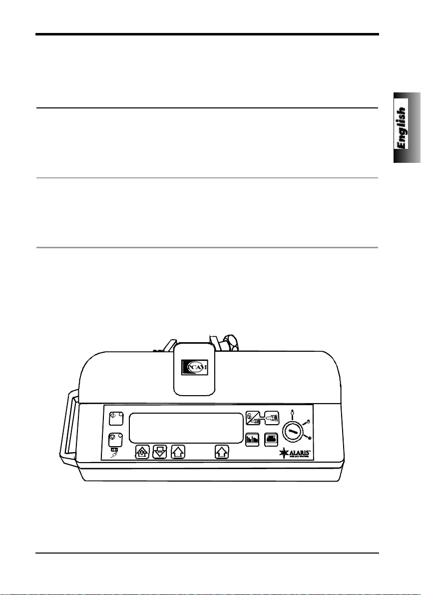
Page 9
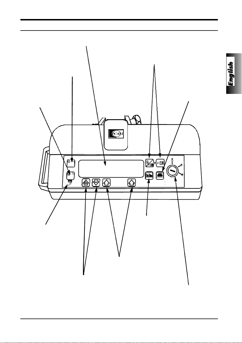
MAIN DISPLAY - For screen
information see Starting the Pump.
START Button - Press START
button to commence PCAM
operation. The GREEN light
will illuminate when the pump
is infusing.
STOP Button - Press to
stop the infusion. The
Amber light will flash to
indicate an alarm.
Getting Started
Controls and Indicators
PURGE Button - Press both PURGE buttons
simultaneously and hold down to purge the
extension line during set up. PURGE will only
operate when the cover is open and the key switch
is in the RUN position.
PRINT Button - Press
PRINT button to print
patient history. A suitable
printer must be connected.
BATTERY & AC POWER
INDICATORS - Indicates
when the unit is running from
its internal battery or
connected to the AC power
supply with the battery being
charged.
Use + and - arrow buttons to move
cursor and increase/decrease
values shown on the display
during setup and configuration.
5001FAOPT71 ISS 8.0
HISTORY Button Press HISTORY
button to display
PCAM history graphs
and event records.
ARROW Buttons - Use
ARROW buttons in
conjunction with prompts
shown in the display.
KEY SWITCH - The KEY SWITCH turns the power
ON/OFF and is used to select SET and RUN modes.
Switching from RUN to SET modes without first pressing
the STOP button will automatically stop the infusion.
3 / 120
Page 10
Getting Started
Operating Precautions
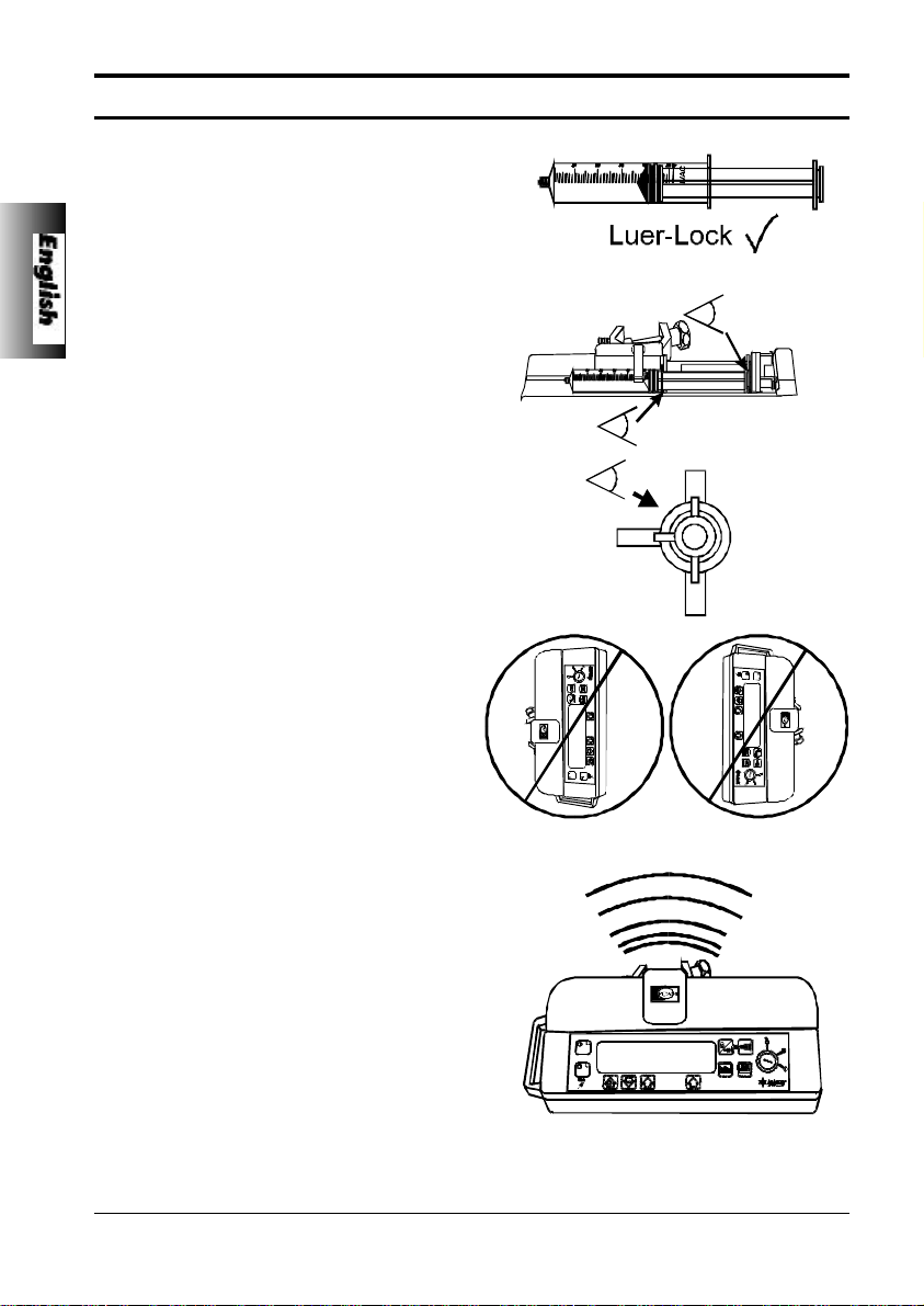
This IVAC pump has been calibrated for use
with single-use disposable syringes. To ensure
correct and accurate operation, only use LuerLock versions of the syringe make specified on
the pump or described in this Directions for
Use. Use of non-specified syringes or
administration sets may impair the operation of
the pump and the accuracy of the infusion.
Uncontrolled flow or syphoning may result if
the syringe is located on the pump without its
finger grips and plunger correctly located in the
slots provided, or if it is removed from the
pump before the extension line is properly
isolated from the patient. Isolation may include
closing a tap in the patient line or activating a
flow stop clamp.
When combining several apparatus and/or
instruments with administration sets and other
tubing, for example via a 3 way tap, the
performance of the pump may be impacted
and should be monitored closely.
Do not mount the pump in a vertical position
with the AC power inlet or the syringe pointing
upwards as this could affect electrical safety, in
the event of a fluid spill over the unit or lead to
an infusion of air which may be in the syringe.
To protect against the introduction of air the
user should regularly monitor the progress of
the infusion, syringe, extension line and patient
connections and follow the priming procedure
specified herein.
This is a positive pressure device designed to
achieve very accurate fluid administration by
automatically compensating for resistance
encountered in the infusion system.
The pumping pressure alarm system is not
designed to provide protection against, or
detection of, infiltration conditions which can
occur at low pressures.
Several alarm conditions detected by this
pump will stop the infusion and generate
audible alarms. Users must perform regular
checks to ensure that the infusion is
progressing correctly and no alarms are
operating.
4 / 120
5001FAOPT71 ISS 8.0
Page 11
Getting Started
Operating Precautions
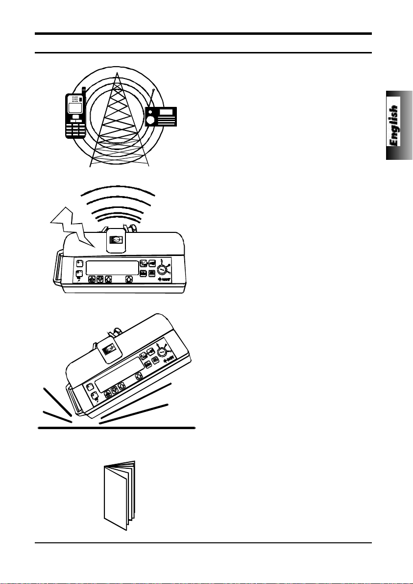
This instrument is protected against the effects
of external interference, including high energy
radio frequency emissions, magnetic fields
and electrostatic discharge (for example, as
generated by electrosurgical and cauterising
equipment, large motors, portable radios,
cellular telephones etc.) and is designed to fail
safe if unreasonable levels of interference are
encountered.
In some circumstances the unit may be
affected by an electrostatic discharge of +/-8kV
(contact), +/-15kV (air), at test levels lower
than these values the unit will operate
normally. In rare circumstances the unit may
be affected by radiation at a level of 10V/m. If
the unit is affected by this external interference
the unit will fail safe or reset, ( a call back alarm
will occur after 2 minutes). Should false alarm
conditions be encountered either, remove the
source of the interference, or regulate the
infusion by another appropriate means.
5001FAOPT71 ISS 8.0
If this instrument is dropped, subjected to
excessive moisture, humidity or high
temperature, or otherwise suspected to have
been damaged, remove it from service for
inspection by a qualified service engineer.
An explosion hazard exists if the instrument is
used in the presence of flammable
anaesthetics. Exercise care to locate the unit
away from any such hazardous sources. An
electrical shock hazard exists if the units
casing is opened or removed. Refer all
servicing to qualified service personnel.
A comprehensive service manual containing
circuit descriptions, servicing and testing
information is available for this unit. It can be
ordered from your ALARIS Medical Systems
authorised distributor (Technical Service
Manual Part Number 5000PB00004).
5 / 120
Page 12

Getting Started
Installation
Check that the pump is complete, undamaged and that the voltage rating specified on the base
plate is compatible with your AC power supply. Items supplied with this ALARIS Medical Systems
syringe pump are;
u IVAC PCAM Mk II
u POLE CLAMP
u DIRECTIONS FOR USE
u AC POWER CABLE (AS REQUESTED)
u PROTECTIVE PACKAGING
Connect the unit to the AC power supply for 24 hours to ensure that the internal battery is fully
charged.
Should the pump fail to perform correctly, replace it in its original protective packaging and contact
a qualified service engineer for investigation.
Pole Clamp
The pole clamp is supplied fitted to the rear of the unit and will provide secure fixing to standard
I.V. poles of a diameter of up to 40mm.
The pole clamp can also be fitted in a choice of 4 fixing positions allowing the unit to be mounted
to vertical and horizontal poles, equipment rails and hospital furniture in a variety of convenient
operating orientations.
The pole clamp may be adjusted for use with horizontal fittings by using the existing fixings screws
with the alternative fixing holes in the pole clamp.
The pole clamp may also be secured to the base of the unit in a choice of four positions.
Do not mount the unit with the AC power inlet or the syringe pointing upwards.
This could affect the electrical safety in the event of a fluid spill or lead to the
infusion of air which may be in the syringe.
Important:
Replacing the Mains Fuses
If the pump continually illuminates the battery symbol and the AC power indicator light does not
illuminate when the pump is connected to the AC power supply and switched ON, suspect that
either, the power supply fuse in the AC power plug, or, the internal fuse has blown.
First check the power supply fuse in the AC mains plug, if the AC power indicator light does not
illuminate remove the pump from service. It is recommended that the mains fuses are only
replaced by a qualified service engineer. For further information regarding the replacement of the
internal fuses refer to the technical service manual.
6 / 120
5001FAOPT71 ISS 8.0
Page 13
Getting Started
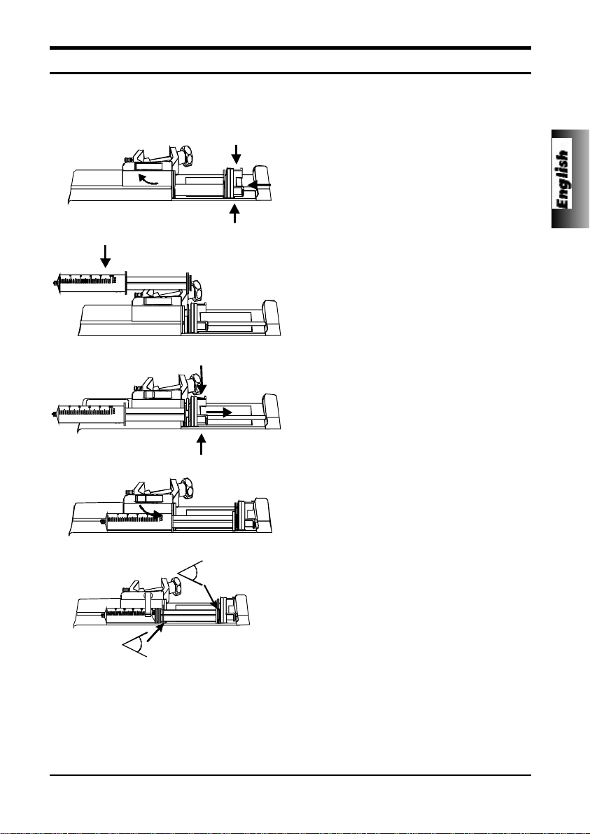
Loading a Syringe
Place the pump on a stable horizontal surface or secure using the pole clamp fitted.
Prepare, load and prime the single use disposable syringe and extension line using standard
aseptic techniques.
1. Squeeze the finger grips on the plunger
holder and slide the mechanism to the left.
Lift the syringe clamp and rotate to the left.
2. Insert the syringe into the slots on the
plunger holder.
3. Squeeze the finger grips on the plunger
holder and slide the mechanism to the right
until the syringe finger flanges locates in
the V slot.
Advance the syringe until the finger
flanges touch the front of the V slot
closest to the syringe clamp. This is
important to prevent delay at the
start of the infusion.
4. Rotate the syringe clamp forward until it
locks onto the syringe barrel.
5. Check that the syringe plunger and finger
flanges are correctly located in their slots.
Important:
Only use a syringe of the type and size indicated in this manual. Using an
incorrect syringe could adversely affect the accuracy of the infusion and the
performance of the pump.
When initially loading the syringe, allow for the volume of fluid contained in the
extension line and retained in the syringe at the end of infusion as this “deadspace” will not be infused.
5001FAOPT71 ISS 8.0
Important:
7 / 120
Page 14
Getting Started
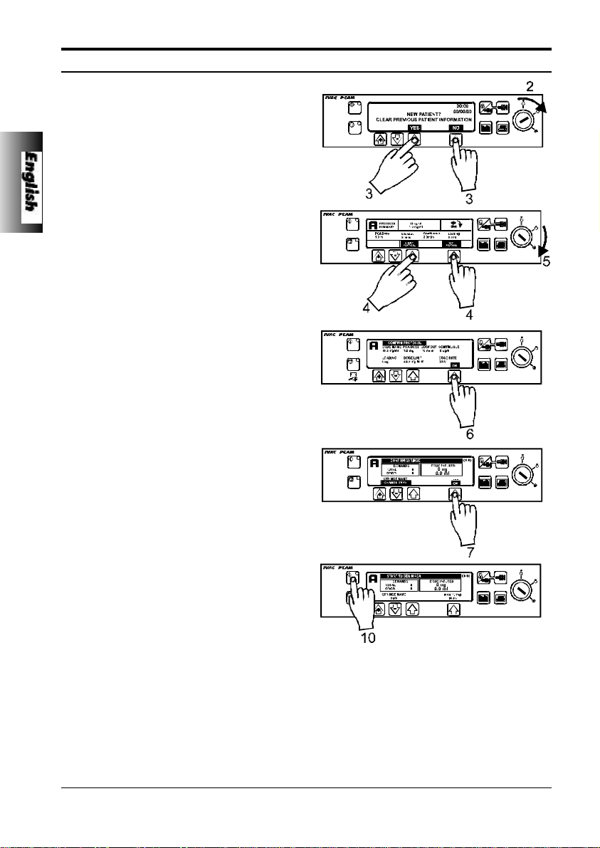
Starting the Pump
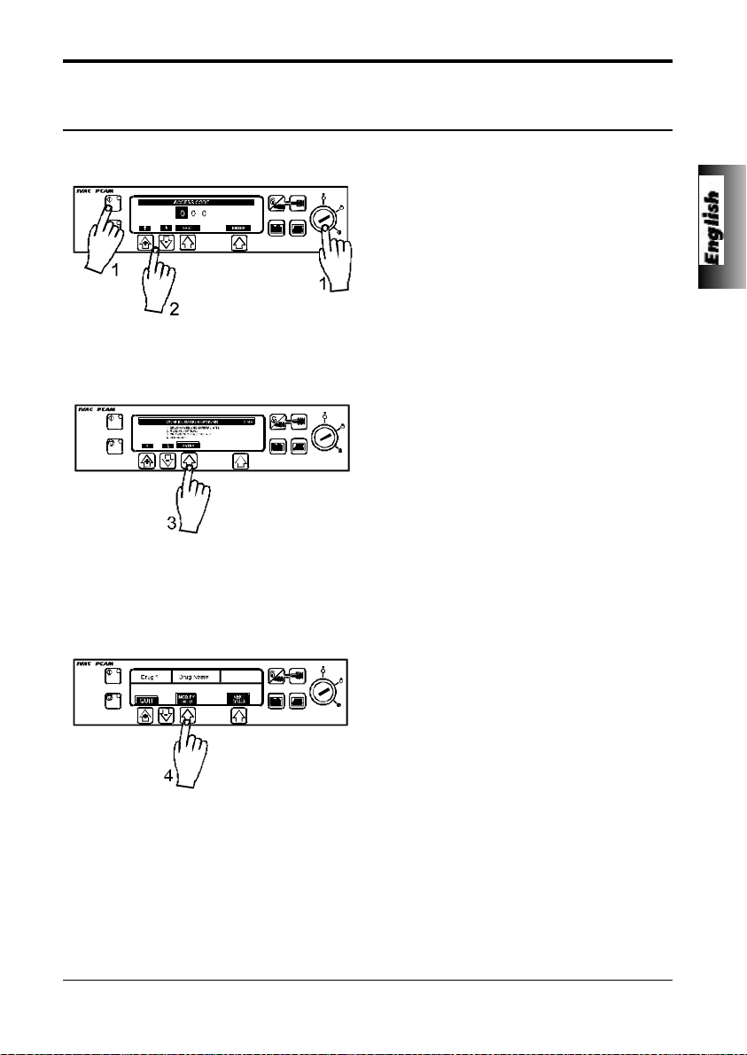
1. AC POWER - Connect unit to AC power
supply using the AC power cable.
2. SET - Insert PCAM key in front panel
switch. Turn to SET position. The unit will
automatically operate from its own internal
rechargeable battery if it is switched ON
without the AC power connected.
3. NEW PATIENT? - Answering NO will retain
all previous patient history. YES will
automatically reset the patient history to
zero. Check time and date is correct and
answer YES or NO.
4. SELECT/ MODIFY PROTOCOL - Carefully
check the protocol displayed. If required,
press MODIFY PROTOCOL to adjust the
current protocol, or, NEXT PROTOCOL to
select an alternative pre-set protocol.
5. RUN - Turn the PCAM key to the RUN
position and remove from unit.
6. CHECK PROTOCOL - Carefully check that
protocol is correct. Press OK.
7. CONFIRM SYRINGE - Check that the
syringe type and size being used matches
display. If required, the make of syringe
can be changed by pressing the CHANGE
TYPE button. Press OK.
8. PURGE (if required) - The PURGE buttons
can only be used when the cover is open
and the key switch is in the RUN position.
When the purge operation is complete
close the cover.
9. CONNECT PATIENT - Connect the PCA
extension line to the patient access device.
Recheck the protocol.
10.START - Press START to commence
PCAM operation. PCA AVAILABLE will be
displayed with the protocol summary,
demand and drug totals. If selected, a
loading dose will be delivered.
The unit will automatically operate from its internal battery if the pump is
switched on without being connected to the AC power supply.
Each time the unit is switched ON, check that the alarm beeps twice and that all
the segments of the display, the green and amber lights are illuminated during the
self test routine.
The Key Switch should not be turned from OFF to SET whilst the syringe extension
line is connected to the patient.
8 / 120
Important:
5001FAOPT71 ISS 8.0
Page 15
Getting Started
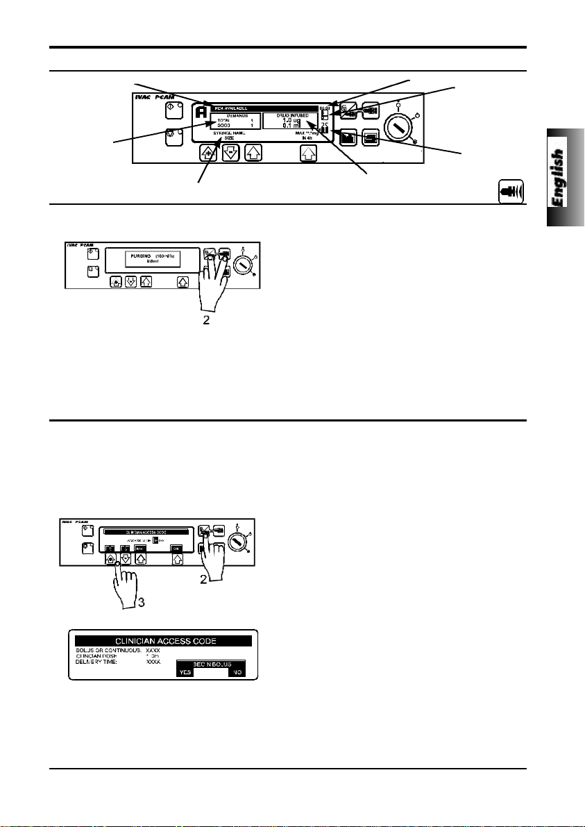
Front Panel and Main Display
Pump Status
Time
Demand
Status
Drug Infused
Current Protocol & Syringe Type
The PURGE button allows the delivery of a limited volume of fluid in order to purge the extension line prior to
being connected to a patient.
1. PURGE can only be operated with the cover
opened and the key switch in the RUN position.
2. Press the PURGE buttons together until fluid
flows and priming of the syringe extension line is
complete. The audible alarm will operate during
use of the PURGE buttons and the volume used
during priming will be shown in the volume
infused display.
The purge feature is not activated when the cover is closed. Ensure that the extension line
is disconnected from the patient before purging the line. No alarms are disabled during the
operation of the purge feature.
Important:
Clinician Over-ride
The clinician over-ride feature can be used in RUN mode to administer an additional bolus dose or continuous
background infusion of a limited dose and duration, for example during the PCA lock out period. The clinician
over-ride is a special feature which can be configured according to the specific clinical situation. Clinician override can also be used in SET mode to allow modification of the pre-set PCA Protocol when this option has been
disabled for normal use.
1. Turn key to RUN position and ensure green light is
illuminated on the STARTbutton.
2. Press and hold down the CLINICIAN OVER-RIDE
button for 2 seconds.
3. Use “+” and “-” arrows and NEXT button to enter
three figure pre-programmed clinician access code
“n n n”. See technical service manual.
4. Select BOLUS or CONTINUOUS.
5. Use “+” and “-” arrows to select the dose delivered,
when the correct value has been entered press
OK.
6. Use “+” and “-” arrows to select period over which
the dose is to be delivered. Press OK when correct
time has been entered.
7. BEGIN BOLUS? YES - Clinician bolus /
continuous infusion will be delivered to the patient.
NO - Quit set up and return to normal operation.
The delivery of the clinician over-ride continuous infusion will automatically halt while a
Patient or Clinician over-ride bolus is being administrated. To cancel clinician over-ride
during delivery, press STOP and press the YES softkey.
Important:
Pumping
Pressure
Maximum
Dose
Purge
5001FAOPT71 ISS 8.0
9 / 120
Page 16
Getting Started
PCAM Patient History
Each time the PCAM unit is switched ON it will ask if this is a new patient. Pressing YES will
provide opportunity to re-set patient history. Pressing NO continues with the current protocol and
retains all protocol records, event history, graphs etc.
The PCAM will retain the events in a rolling memory. Following selection of a new patient, it
remains possible in technician mode to access previous patient(s) history still held in memory.
Patient history can be accessed at any time by pressing the HISTORY button. PCAM provides a
clear rolling 24 hour graphical representation of the PCA demand pattern and the drug
administered to the patient. The graphs are updated when the history button is pressed and give
values for each completed hour and the current hour.
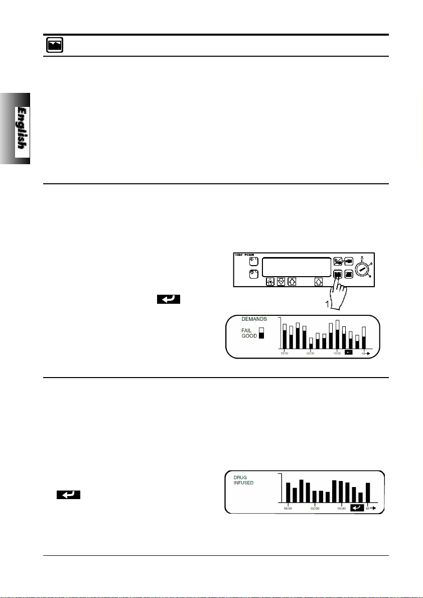
PCA Demands
Provides a record of the last 24 hours good and failed PCA demands. The good demands are
indicated by the shaded section of the graph and the failed demands by the clear section. The
latest hour is shown at the right side of the display.
This graph provides a clear picture of good and bad PCA demands and pattern of the patients
usage. Used in conjunction with the PCA Demands graph, this display helps to indicate if the PCA
protocol needs modification and when to end treatment.
1. To access the PCA demand graph press
the HISTORY button once.
2. To exit the screen press the BACK softkey.
3. To scroll through to the next History screen
press the HISTORY button.
Drug Infused
Record of the total amount of drug administered to the patient over the last 24 hours. The latest
hour is shown at the right side of the display. This graph provides a clear picture of the actual
drug administered, including loading dose, continuous background infusions, clinician over-rides
and protocol changes.
Used in conjunction with the PCA Demands graph, this display helps to indicate relative pattern
of the demand pattern and the actual drug administered.
1. To access the PCA demand graph press
the HISTORY button twice.
2. To return to the previous screen press the
BACK softkey.
3. To scroll through to the next History screen
press the HISTORY button.
10 / 120
5001FAOPT71 ISS 8.0
Page 17
Getting Started
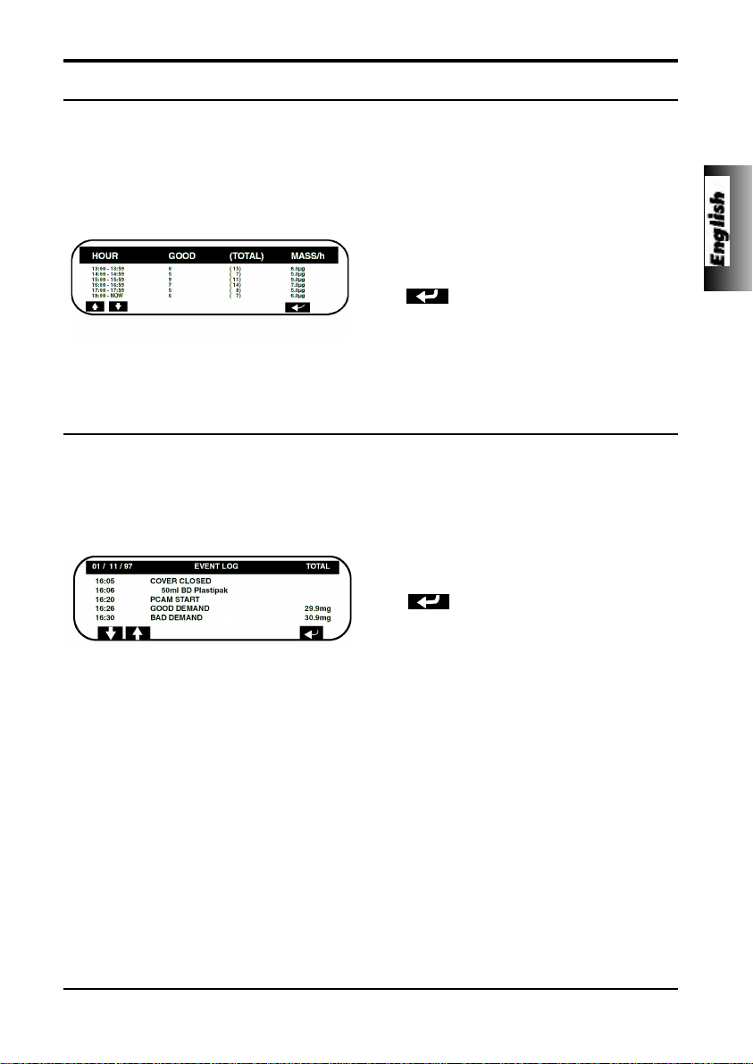
24 Hour Review
An hour by hour record of the last 24 hours, showing good and total PCA demands along with the
total dose per hour.
This information provides the accurate demand pattern and drug infused values from which the
other graphs are derived.
1. To access the PCAM 24 Hour Review
press the HISTORY button three times.
2. To return to the previous screen press the
BACK softkey.
3. To scroll through to the next History screen
press the HISTORY button.
PCAM Event Log
Record of events since "NEW PATIENT" selected. Including, protocol selection and changes,
patient demands etc. The event log will also record all alarms.
All events are recorded against date, clock and total drug infused.
1. To access the PCAM Event Log press the
HISTORY button four times.
5001FAOPT71 ISS 8.0
2. To return to the previous screen press the
BACK softkey.
3. To return to the Protocol Summary press
the HISTORY button again.
11 / 120
Page 18
Getting Started
Printing
A printer fitted with a serial interface (or cable with parallel to serial converter) can be connected
to the PCAM unit, either during normal PCA operation, or, following use. Printing patient history
provides a permanent record and can be used for analysis away from the bedside.
All patient history, including protocols and the 24 hour demand pattern and drug dose
administered graphs are available for printing.
When connected to the printer, the PCAM can also be configured to provide line by line
continuous printing of all events, patient demands etc. as they occur at the bedside. See General
Options.
Continuous Mode
Enable Continuous printing by selecting YES in General Options.
1. Connect printer.
2. All events will be printed as they occur.
Protocol Summary - connect printer
1. Turn key to SET position.
2. Press PRINT button.
3. All protocol information will be printed with
patient header.
Patient History - connect printer
1. Press PRINT button.
2. All protocol information, demand and drug
totals, 24 hour graphs and records will be
printed with patient header.
Event Log - connect printer
1. Press HISTORY button until event log is
displayed.
2. Use ARROW buttons to position display at
start point for events to be printed.
3. Press PRINT button.
4. All events will be printed from information
on screen forward with time, date and
patient header.
Event Log at New Patient - connect printer
1. Press PRINT button.
2. All events will be printed from the patient
event log.
12 / 120
5001FAOPT71 ISS 8.0
Page 19
Getting Started
Pumping Pressure Icon
The PUMPING PRESSURE ICON can be used to
provide a constant visual indication of the current
pumping pressure and the pressure level at which
the alarm will operate. As the pressure required to
administer the infusion increases, the box will be
filled until the pressure reaches the alarm level.
The pump will then stop infusing and the
occlusion alarm will operate.
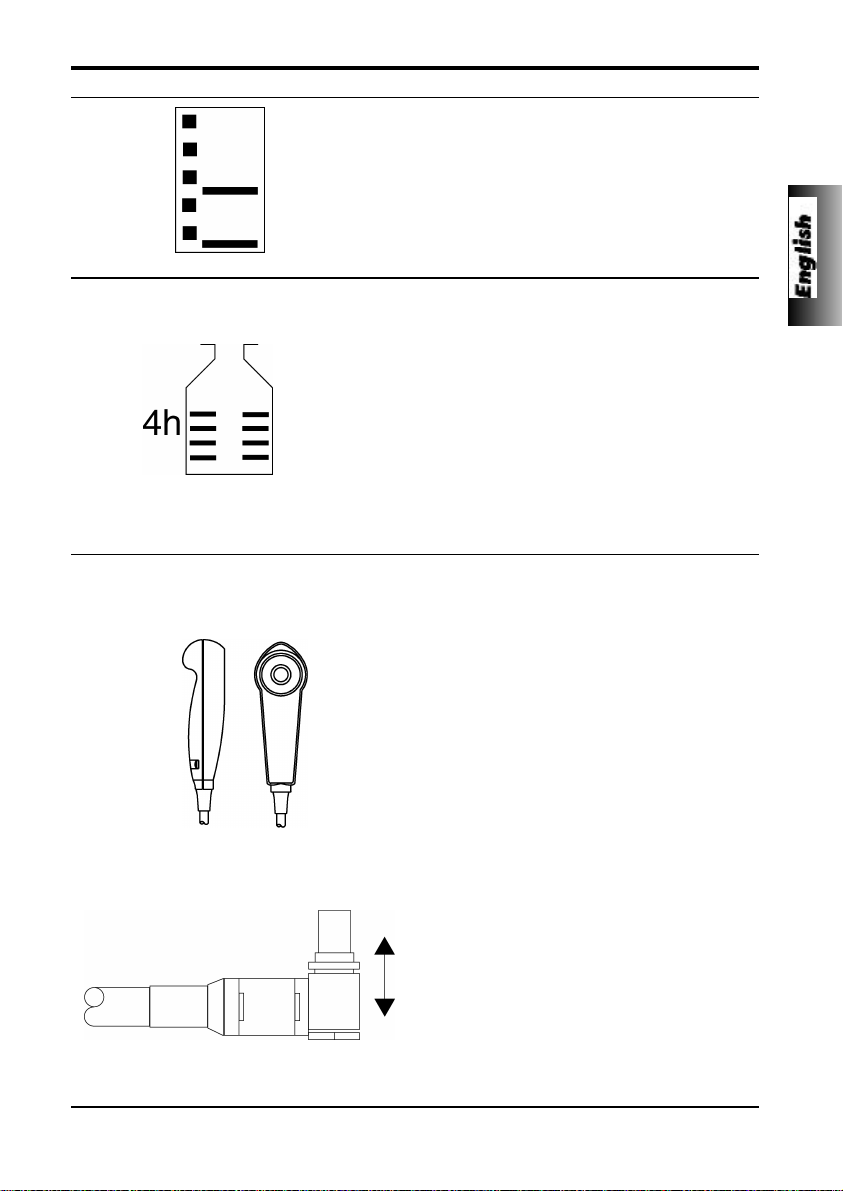
Maximum Dose Icon
The MAXIMUM DOSE ICON provides an
indication of the amount of drug that has been
administered during the limit period. The limit
period is displayed alongside the bottle and the
bottle fills up as doses are added to the mass
infused. The bottle will appear to be full if the dose
limit reaches the alarm level and the pump will
then stop infusing. A message “Max Dose Limit”
will be displayed and the icon will flash until
dosing is less than the maximum dose limit.
Clinician override is always available.
Refer to GENERAL OPTIONS for instructions for
displaying icons in the main display.
PCAM Patient Hand Set
The patient hand set supplied with the PCAM is designed to be ambidextrous and suitable for both adult
and paediatric use. The hand set provides an indicator light which clearly shows when the PCAM is
available and can be configured to flash when a PCA dose is being delivered.
The indicator on the patient hand set will reflect
the configuration of the PCAM system and will
provide feed-back on all, or just good demands,
and the indicator light can be disabled should the
clinical situation require.
Where appropriate the hand-set can be
configured so that the patient will not need to refer
to the instrument to assess if PCA is being
delivered, or is available.
The hand set is provided with a clip for attaching
it to bedding or clothing.
The PCAM concept is that the patient can be instructed in the use of the hand set as it will carry all the
information required by the patient using PCA. This design simplifies patient instruction and encourages
a smooth transfer to alternative devices used to treat long term chronic pain, should this be indicated.
A latching (but non locking) connector makes the
hand set easy to fit. To remove, hold the body of
the connector and pull away from the pump.
An alarm warning will operate if the hand set is disconnected from the unit while it is in operation or the
hand set is connected to the unit with the PCA button depressed. In addition, the unit can be operated
in continuous or clinician over-ride modes without the hand set connected, should this be indicated.
5001FAOPT71 ISS 8.0
13 / 120
Page 20
Getting Started
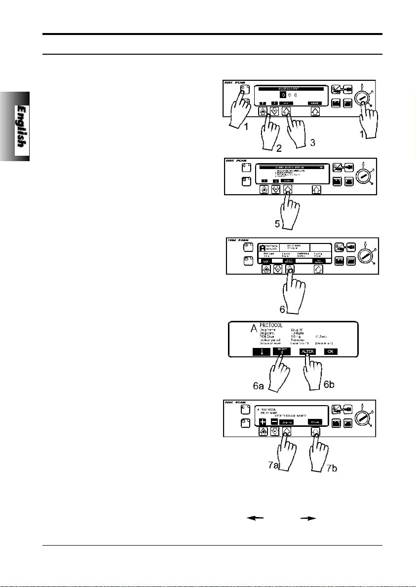
Using Pre-Set PCAM Protocols
Operation of PCAM is greatly simplified by the use of PRE-SET PCA protocols. When the PCAM
key switch is turned to the SET position the unit will automatically display pre-set PROTOCOL A
if NEW PATIENT has been selected, or, display the previous protocol in use if NEW PATIENT has
not been selected.
With the key switch in the SET position, it is possible for the user to modify the pre-set protocol
using the MODIFY PROTOCOL button and select another pre-set protocol using the NEXT
PROTOCOL button.
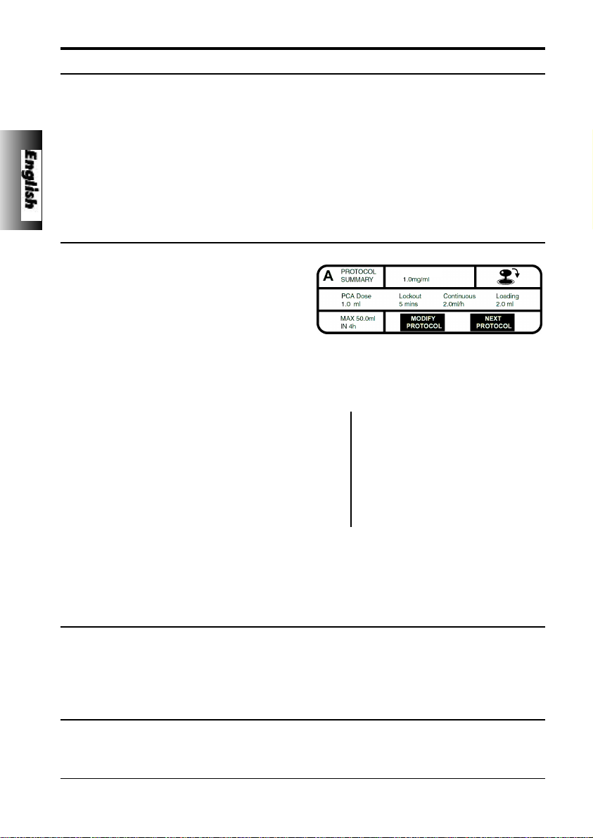
To modify a Pre-Set Protocol
1. Press MODIFY PROTOCOL indicated on
Drug ‘X’
the screen.
2. The protocol summary will be displayed.
Use ARROWS to highlight a field, press
ALTER to enter that field and “+”, “-”
arrows to select desired values.
3. When field is correct press CONFIRM or
CANCEL.
4. Display will show:
Protocol
Drug name Drug ‘X’
A
Drug conc. 1.0mg/ml
PCA Dose 1.0mg (1.0ml)
Lockout period 5 mins
Occlusion level 4
Continuous 0µg/h (0.0ml/h)
Loading dose 0µg (0.0ml)
Max. limit 50mg (50.0ml)
Limit duration 4 hours
PCA delivery STAT
5. Press OK to return to display.
(Note: A modified protocol has no pre-set
letter).
To change to another pre-set protocol
Press NEXT PROTOCOL to display the step through the pre-set protocol.
Pre-set protocols are identified as A to E. When the desired protocol has been selected it can be
used by turning the key switch to the RUN position, or, can be modified using the MODIFY
PROTOCOL.
To confirm protocol
When ever a new protocol is selected, modified or the key switch is turned to the SET position,
the CONFIRM PROTOCOL display will appear. Pressing OK automatically records the protocol
and any changes in the EVENT LOG history.
14 / 120
5001FAOPT71 ISS 8.0
Page 21

Getting Started
Alarm Procedures
Alarms are indicated by a combination of an audible alarm, flashing amber STOP light and a
descriptive message in the display.
1. A continuous audible alarm indicates that
the infusion has stopped. First press MUTE
to silence the alarm for a maximum of 2
minutes, then check the display for an
alarm message. Press STOP to cancel the
alarm message.
2. When the cause for the alarm has been
rectified press START to restart operation.
Display Description
COVER OPENED DURING OPERATION
COVER OPENED
DRIVE DISENGAGED
The cover has been opened, or cover lock operated,
during operation. Check cover and lock.
PUMP DRIVE DISENGAGED
The drive system has been disengaged during
operation. Unlock and open the cover. Check the finger
grips and the position of the syringe.
LINE OCCLUSION
SYRINGE ERROR
CHECK HANDSET
5001FAOPT71 ISS 8.0
EXCESSIVE PUMPING PRESSURE
Pumping pressure has reached the alarm limit. Unlock
and open the cover, squeeze finger grips on the plunger
holder to release the drive mechanism and relieve any
excessive pressure in the syringe and patient line.
Identify and remove the cause of the blockage in the
drive, syringe, or administration system before
restarting the infusion.
SYRINGE SIZE ERROR / FITTED INCORRECTLY
Incorrect size of syringe has been fitted, the syringe
clamp has not been positioned correctly on the syringe
or has been disturbed during operation or plunger is not
fitted in plunger slot. Unlock and open the cover, check
syringe size, position of syringe clamp, syringe and
plunger.
PATIENT HAND SET FAILURE
Patient hand set has become faulty or disconnected
during operation. Check operation and connection of
the hand set to the unit. Press START to continue if
operation without the hand set is required.
15 / 120
Page 22

Getting Started
Alarm Procedures
BATTERY CHARGE LOW WARNING
Battery charge low with 30 minutes operation
remaining. Battery indicator will flash and after 30
minutes a continuous audible alarm will indicate that the
battery is exhausted. Reconnect to AC power supply to
continue operation and charge internal battery.
BATTERY EXHAUSTED
Internal battery exhausted. To silence the alarm switch
the key switch to the OFF position and reconnect unit to
AC power supply. Restart operation on AC power whilst
charging the internal battery. Switch to the RUN
position.
NEAR END OF SYRINGE WARNING
Syringe almost empty with about 6% of its volume
remaining. Press START to silence alarm and continue
operation. Display will flash SYRINGE NEAR EMPTY.
SYRINGE EMPTY - END OF INFUSION
The pump has reached the end of the infusion. About
1% of the syringe volume will remain in the syringe
helping to prevent the infusion of air bubbles into the
PCA set.
DisplayDescription
BATTERY LOW
BATTERY EXHAUSTED
SYRINGE NEAR EMPTY
SYRINGE EMPTY
AC POWER SUPPLY DISCONNECTED WARNING
AC Power has been disconnected and the pump is
operating on battery power. Reconnect AC power
supply or press STOP to silence the alarm and continue
battery operation. The display will light up ON
BATTERY. The alarm will automatically cancel if the AC
power supply is reconnected.
INTERNAL MALFUNCTION
The alarm system has detected an internal malfunction.
Note the malfunction code. Remove unit from service
for examination by a qualified service engineer.
AC POWER FAIL
MALFUNCTION
Alarm Procedures - Alarms without screen prompts
Description
NURSE ATTENTION WARNING
Unit left switched ON for over 2 minutes without
starting operation. Press STOP or any of the control
buttons to silence the alarm for a further 2 minutes.
16 / 120
3 BEEPS
5001FAOPT71 ISS 8.0
Page 23
Configured Options
For technician access codes please refer to the Technical Service Manual.
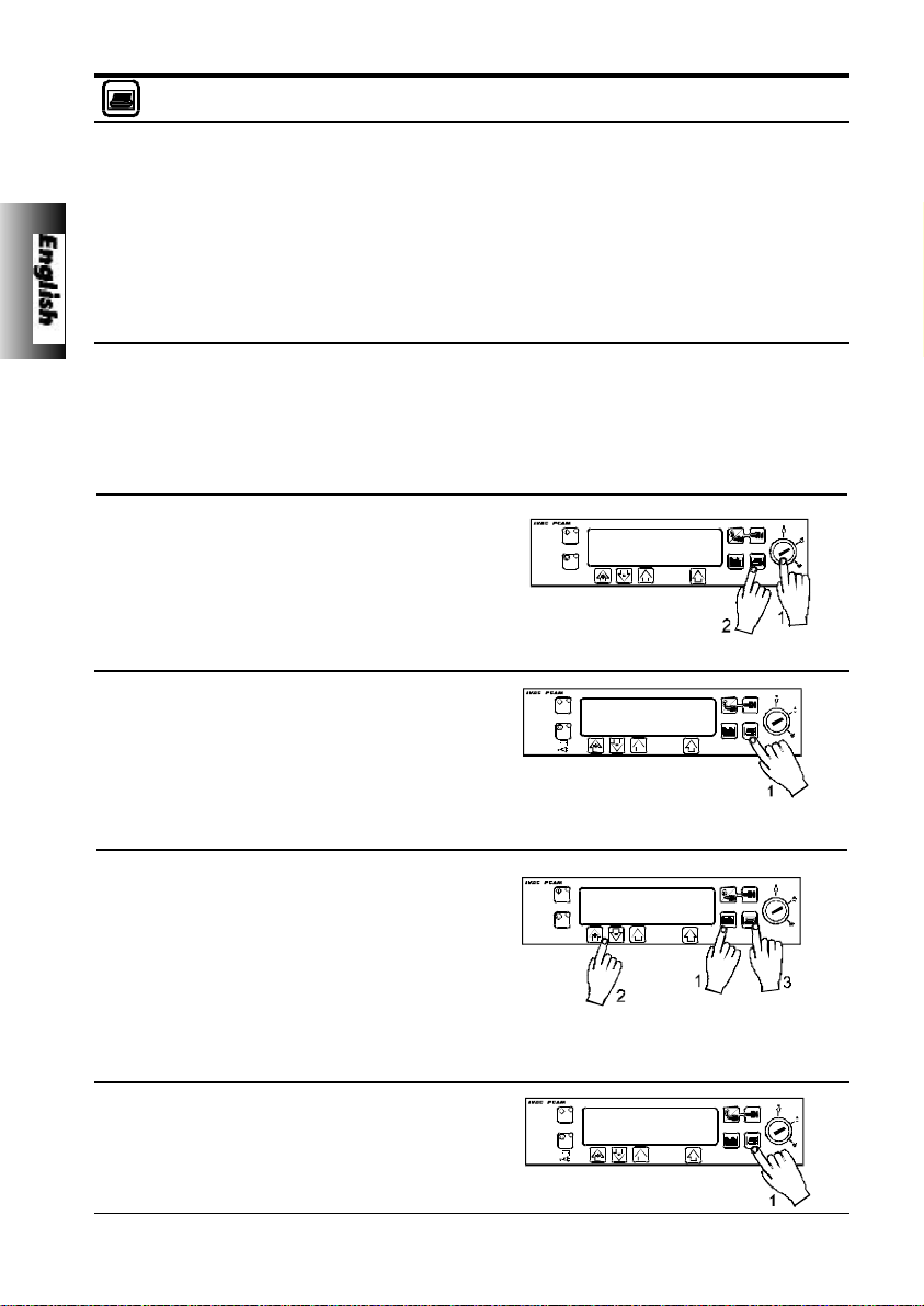
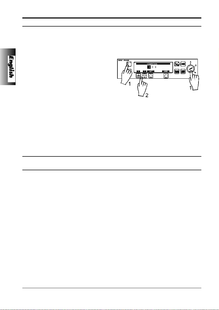
Drug Names and Safety Limits
1. Turn key switch to SET position while
pressing down START button.
2. Enter the access code using the rate
selection arrows.
3. Select DRUG NAMES AND SAFETY
LIMITS from the menu. Press ENTER.
4. Press MODIFY DRUG to modify the drug
summary. Use “+” and “-” arrows to select
desired values. When field is correct press
OK to store the selection.
5. NAME: Use “+” and “-” arrows to set
highlighted letter. Press NEXT for next
character (up to ten letters). Press OK
when complete.
6. MIN DRUG CONC: Use “+” and “-” arrows
to set minimum concentration. Press OK
when complete.
7. MAX DRUG CONC: Use “+” and “-” arrows
to set maximum concentration. Press OK
when complete.
5001FAOPT71 ISS 8.0
8. MIN LOCKOUT PERIOD: Use “+” and “-”
arrows to set minimum lockout period.
Press OK when complete.
9. MAX LOCKOUT PERIOD: Use “+” and “-”
arrows to set maximum lockout period.
Press OK when complete.
10.MIN PCA DOSE: Use “+” and “-” arrows to
set minimum PCA dose. Press OK when
complete.
11. MAX PCA DOSE: Use “+” and “-” arrows to
set maximum PCA dose. Press OK when
complete.
12.MAX CONTINUOUS: Use “+” and “-” to set
maximum continuous rate. Press OK when
complete.
17 / 120
Page 24
Configured Options
Drug Names and Safety Limits
13.MAX LOADING DOSE: Use “+” and “-”
arrows to set maximum loading dose.
Press OK when complete.
14.MAX DOSE LIMIT: Use “+” and “-” arrows
to set maximum dose limit. Press OK when
complete.
15.MAX CLINICIAN BOLUS: Use “+” and “-”
arrows to set the maximum clinician bolus.
Press OK when complete.
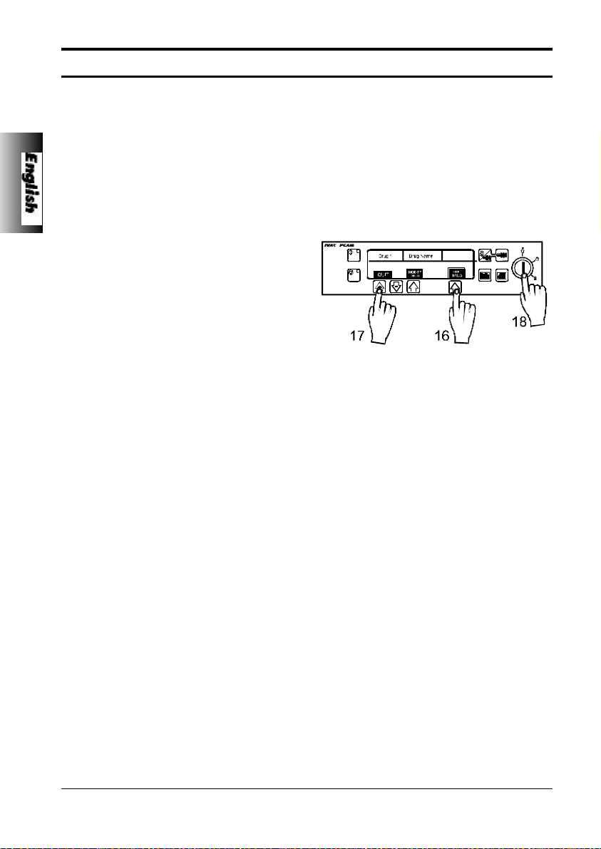
16.NEXT DRUG to display the next drug
name and the safety limits. The five pre-set
drug protocols are identified as 1 to 5.
17.Press QUIT to exit and return to
configuration menu.
18.When set-up is complete, turn key switch
to OFF position to save selection and to
turn PCAM off.
18 / 120
5001FAOPT71 ISS 8.0
Page 25
Configured Options
General Options
General options allow PCAM to be configured to suit the specific requirements of a particular
clinical situation. The selected options should be recorded on the CONFIGURATION RECORD
sheet for reference.
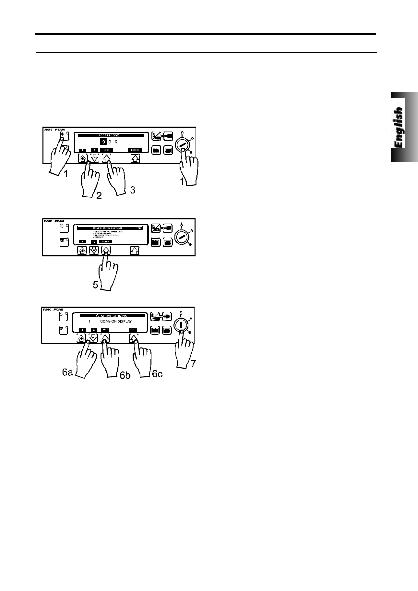
1. Turn key switch to SET position while
pressing down START button.
2. Enter access code using the rate selection
arrows.
3. Enter the first digit and press NEXT
indicated on the screen.
4. When the complete code has been entered
press ENTER.
5. Select GENERAL OPTIONS. Press
ENTER.
5001FAOPT71 ISS 8.0
6. Use "+" and "-" arrows to select
values/options, press NEXT to move to the
next option and QUIT to return to menu.
7. When set-up is complete, turn key switch
to OFF position to save selection.
19 / 120
Page 26

Configured Options
General Options
The general options available are as follows:
1. ICONS on display YES - displays Pumping Pressure and Maximum Dose ICONS.
2. Protocols in use PCA pre-set protocols to be available. Select number from 1 to 5.
3. Modify protocol YES - allows protocols to be modified in SET mode.
4. Handset mode MODE A B C
5. Delayed call-back YES - call-back alarm can be delayed from 10 mins up to 90 mins.
6. Display Sleep YES - display goes blank after 2 minutes.
7. Chirp low alarms YES - "chirp" alarm during use on battery/near end.
8. Continuous infusions YES - Continuous infusions option in protocols.
9. Loading doses YES - Loading dose option appears in protocols. To activate this option "NEW
10. Max. dose limits YES - Dose limit option appears in protocols.
11. Variable dose rates YES - Variable dose rate option available.
12. Comms identity number Use arrows to set pump identity (between 000 and 127) for use with remote
13. Comms enabled YES - RS232 Communications enabled.
14. Nurse call YES - Nurse call connector enabled.
15. Nurse call inverted YES - Nurse call inverted enabled.
16. Continuous Print YES - Allows printing of events as they happen.
17. Default Syringe YES - Default syringe enabled.
18. Lock syringe type YES - Syringe type locked to default syringe.
19. Quiet mode YES - Quiet mode enabled.
20 / 120
NO - ICONS disabled.
NO - removes modify protocol option in SET mode.
BEEP GOOD ALL ALL
HAND SET LIGHT:
PCAM STOPPED OFF OFF OFF
PCA AVAILABLE ON ON ON
PCA DELIVERING FLASH ON FLASH
PCA LOCK-OUT OFF ON ON
NO - call-back will be cancelled for up to 2 mins or extended to 15 mins. To
extend call-back alarms, press and hold the stop key for 4 seconds .
This allows the time to be extended.
NO - display stays on during operation.
NO - no "chirp" alarm.
NO - Continuous infusions are not available.
PATIENT" is confirmed. The protocol also includes the loading dose. Start the
PCA.
NO - Loading doses are not available.
NO - Dose limits are not available.
NO - Loading doses are not available.
communications.
NO - RS232 Communications disabled.
NO - Nurse call connector disabled.
NO - Nurse call inverted disabled
NO - Continuous printing disabled.
NO - Default syringe disabled
NO - Syringe type not locked to default syringe.
NO - Quiet mode disabled.
5001FAOPT71 ISS 8.0
Page 27
The internal clock is used to record patient history.
Configured Options
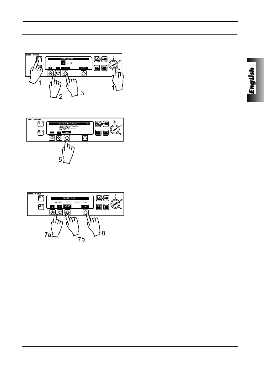
Clock Set
1. Turn key switch to SET position while
pressing down START button.
2. Enter access code using the rate selection
arrows.
3. Enter the first digit using the selection
arrows and press NEXT indicated on the
screen.
4. When the complete code has been
entered press ENTER.
5. Select CLOCK SET from Menu. Press
ENTER.
6. Display will show current date and time
programmed into unit.
7. UP/DOWN ARROWS
Use "+" and "-" arrows to change values in
the highlighted field. When entry is correct
press NEXT to move highlight from left to
right.
8. Press OK to save the date and time.
The internal clock is the reference against which the PCAM unit stores patient
history and events. Changing the clock will automatically reset the dates against
which all new patient history is stored in the unit and may effect the presentation
of the history graphs
Patient history should always be recorded and, if required, printed prior to
changing the clock.
5001FAOPT71 ISS 8.0
Important:
21 / 120
Page 28
Configured Options
Pre-Set Protocol Set Up
Pre-set Drug names and safety limits apply to pre-set protocols during protocol selection and
modification.
1. Turn key switch to SET position while
pressing down START button.
2. Enter access code using rate selection
arrows.
3. Enter first digit and press NEXT indicated
on the screen.
4. When the complete code has been entered
press ENTER.
5 Select PROTOCOL DEFAULT SET-UP
from the menu. Press ENTER.
6. Press MODIFY PROTOCOL to display
current protocol summary. Use ARROWS
to highlight a field, press ALTER to enter
that field and "+" and "-" arrows to select
desired values.
7. When field is correct press CONFIRM or
CANCEL. Press OK to return to protocol
summary.
Note:
One of the five drugs programmed in the Drug Names and Safety Limits are
selectable for each protocol. Additionally a default drug with limits set to
extremes may be chosen and is indicated by “ DRUG “.
22 / 120
5001FAOPT71 ISS 8.0
Page 29

Specifications
RS232 / Nursecall Feature
The RS232 / Nursecall feature fitted to this IVAC “P” Series Syringe Pump allows the pump to be
monitored remotely and/or controlled via a suitable central monitoring or computer system.
When the pump is started by a command from the serial interface, communication must take
place over the serial interface, a communication must take place every 15 seconds or the pump
will alarm, display communications failure and stop infusing. This failure protects against failure
of the communications, including the removal of the RS232 cable.
The nursecall interface provides a remote backup to the internal audible alarm.
It should not be relied upon to replace monitoring of internal alarm.
Refer to the technical service manual for further information regarding the
RS232 interface. Since it is possible to control the syringe pump using the RS232
interface at some distance from the pump and hence remote from the patient,
responsibility for the control of the pump is vested in the software run on the
computer control system.
The assessment for the suitability of any software used in the clinical
environment to control or receive data from the pump lies with the user of the
equipment. This software should include detection of the disconnection or other
failure of the RS232 cable. The protocol is detailed in the technical service
manual and is for general information only. This relates to IVAC “P” Series
Syringe pumps fitted with the RS232 communication interface.
Any connected analogue and digital components are required to meet EN60950
for data processing and EN60601 for medical devices. Anyone connecting
additional devices to the signal input or output is a system configurator and
responsible for meeting the requirements of the system standard EN60601-1-1.
Important:
5001FAOPT71 ISS 8.0
23 / 120
Page 30
Specifications
Self Test Routine
The self test routine is designed to allow confirmation of many of the pump functions, defaults and
calibrations without requiring internal inspection. It does not represent a full calibration check.
1. Turn key switch from OFF to SET while
holding down the START button.
2. Enter “1 2 3” using the “+” , “-” and NEXT
buttons.
3. Press ENTER to commence self test
sequence.
4. The unit will now proceed through a series
of tests as described below.
5. Press NEXT button to move to next test.
Should the pump fail the test sequence, it should be taken out of service and
Important:
inspected by a qualified service engineer.
Self Test Sequence
Display
1. SOFTWARE
REVIEW
2. SYRINGE REVIEW
3. -:- - v
4. “BEEP”
5.
6. Press S1
Test Description
SOFTWARE/SET UP REVIEW: Including software version, program crc,
language, communications fitted.
REVIEW SET UP OF SYRINGE CALIBRATION DATA: Including syringe
calibration, occlusion calibration and syringe range.
INTERNAL PSU VOLTAGE:
AUDIBLE ALARM TEST: Check alarm sound continuously.
DISPLAY AND BACKLIGHT DIM TEST: Check that all the display is
operating and that the display operates on a full backlight for the first part
of the test, dims for the second and then switches off at the end of the
test.
TOUCH PANEL SWITCH TEST: Press buttons in turn from S1 to S10
form START to PURGE until end of test is reached.
24 / 120
5001FAOPT71 ISS 8.0
Page 31

7. LED’s Flashing
Specifications
Self Test Sequence
INDICATOR LED TEST: Check that the STOP and START LED’s are
flashing.
8. DECLUTCH
9. EOI opto:0
10. Grid opto :0
11. Plunger opto:1
12. Motor/encoder:1
13. Cover detect:0
14. Syringe pot:_ _ _
15. Beam value:_ _ _
DECLUTCH SWITCH TEST: Squeeze plunger holder finger grips and
check that the display alternates between 1 (engaged) and 0
(disengaged - finger grips squeezed together).
NEAR END OF INFUSION TEST: Starting with an empty, extended
50/60ml syringe on the unit, squeeze the finger grips and move the
plunger holder slowly to the left.
Check the display switches from 0 to 1. The position at which the display
changes will depend on the syringe type being used. ( For example 6ml
on a B-D Plastipak 50/60ml syringe and 3ml on a Terumo 50ml syringe see Technical Service Manual for values).
LINEAR GRID TEST: Squeeze the finger levers and position the drive
mechanism to the right then slowly move the syringe plunger to the left
observing the display alternate between 0 (OPTO over slot) and 1 (OPTO
over bar).
PLUNGER DETECTOR TEST: Press plunger plate button. Check the
display switches from 1 ( No syringe fitted) to 0 ( Syringe plunger fitted).
MOTOR ENCODER TEST: Motor is pulsed while encoders are tested.
COVER DETECT TEST: Open and close the cover. Check that display
changes from 0 (cover open) to 1 (cover closed).
SYRINGE SIZE DETECTION SYSTEM: Lift syringe clamp and check
that the number shown in the display increases within the normal range
(approx. 045 to 215).
PUMPING PRESSURE DETECTION TEST: Remove syringe and
confirm that value is within normal range (-020 to +020). Gently press
back on the plunger holder and observe the value increase.
16. Handset: OFF
17. Key switch : SET
18. Nursecall on/off/on....
19. CONFIGURATION
SUMMARY
20. NEXT
5001FAOPT71 ISS 8.0
PATIENT HAND SET TEST: Connect patient hand set. Check display
switches from OFF to ON as the button is pressed.
KEY SWITCH TEST: Turn key from SETposition to RUN position. Check
display changes.
Summary of user defined options selected.
Returns unit to normal operation.
25 / 120
Page 32

Specifications
Configuration Record
Use the following sheet to record the configuration settings.
1 Icons _______YES - Display icons.
2 Protocols in use _______1 to 5 protocols.
3 Modify protocol _______YES - to allow modify in SET.
4 Handset Mode _______A, B or C.
5 Delayed Callback _______YES - callback alarm after 2 mins
6 Display Sleep _______YES - display blank after 2 mins.
7 Chirp low alarms _______YES - "chirp" alarm.
8 Continuous infusions _______YES - Continuous infusions.
9 Loading doses _______YES - Loading dose available.
10 Max dose limits _______YES - Dose limits available.
11 Variable dose rates _______YES - Variable rates available.
12 Comms pump identity _______Use arrows to set pump identity in range "1" to "127".
13 Comms enabled _______YES - Communications enabled.
14 Nurse call _______YES - Nurse call connector enabled.
15 Nurse call inverted _______YES - Nurse call inverted enabled.
16 Continuous Print _______YES - Continuous printed enabled.
17 Default syringe _______YES - Default syringe enabled.
18 Lock syringe type _______YES - Syringe type locked to default syringe.
19 Quiet mode _______YES - Quiet mode enabled.
_______NO - Icons off.
_______NO - to disable.
_______NO - call-back will be cancelled for up to 2 mins or extended
to 15 mins. To extend call-back alarms, press and hold the
stop key for 4 seconds. This allows the time to be extended.
_______NO - display stays on.
_______NO - no "chirp" alarm.
_______NO - Disabled.
_______NO - Disabled.
_______NO - Disabled.
_______NO - Disabled.
Default setting is "0 0 0".
_______NO - Communications disabled.
_______NO - Nurse call connector disabled.
_______NO - Nurse call inverted disabled.
_______NO - Continuous print disabled.
_______NO - Default syringe disabled.
_______NO - Syringe type not locked to default syringe.
_______NO - Quiet mode disabled.
26 / 120
5001FAOPT71 ISS 8.0
Page 33

Specifications
Symbol Definition and Equipment Classifications
Attention (Consult accompanying documents)
Potential Equalisation Connector
RS232/Nursecall Connector (Optional)
Class II Equipment
Type CF Equipment (Degree of protection against electrical
shock)
IPX4
Electrical/Mechanical Safety - Complies with IEC601-1 1998 (EN60601-1:1993) and IEC60601-2-24
(EN60601-2-24-1998).
EMC - Complies with BS EN 60601-1-2 and BSEN60601-2-24-1998.
5001FAOPT71 ISS 8.0
Protected against splashing fluid (Degree of protection
against fluid ingress)
Alternating Current
Device complies with the requirements of the EC Directive
93/42/EEC. Registered with the CE Mark.
27 / 120
Page 34

Specifications
Syringe Types
The unit is calibrated and labelled for use with single use disposable Luer-lock syringes. Only
use the size and type of syringe specified on the pump display.
Options include:-
IVAC ü ü
BD Plastipak ü ü ü
Terumo ü ü ü
B Braun Omnifix ü ü ü
Sherwood Monoject ü ü ü
PR Pronto ü ü(35ml) ü
Once ü
Fresenius Injectomat ü
B Braun Perfusor ü
BD Worldwide ü ü ü
Janpol ü
Rapiject ü
20ml 30ml 50ml 100ml
Compatible Extension Lines and Syringes
The unit uses a standard, single use, disposable extension line and syringes with Luer-lock
connectors, of type designed for use on syringe pumps.
30602N IVAC 50/60ml Luer-Lock syringe
30120 IVAC100/120ml Luer-Lock syringe
PCA Sets:
30822 Extension line, Microbore
30832 Extension line with y-site, check-valve, Microbore
30842 Short extension line with y-site, check-valve and injection port, Microbore
30852 Extension line with y-site, check-valve and anti-siphon-valve, Microbore
30862 Standard extension line with anti-siphon-valve Microbore
Standard Sets:
G40015 Standard syringe extension set - 150cm
G40020 Standard syringe extension set - 200cm
G40615 Low sorbing syringe extension set - 150cm
G40620 Low sorbing syringe extension set - 200cm
G40215 Opaque syringe extension set - 150cm
G40320 Opaque syringe extension set - 200cm
It is recommended that the extension sets are changed according to the hospital protocol.
28 / 120
5001FAOPT71 ISS 8.0
Page 35

Specifications
CONCENTRATION RANGE:
1µg/ml - 999µg/ml in 1µg/ml steps
0.1mg/ml - 99.9mg/ml in 0.1mg/ml steps
PCA DOSE RANGE:
Mass Mode: 0.0µg - 999µg in 1µg steps
Volume Mode: 0.0ml - 99.9ml in 0.1ml steps
PCA DELIVERY RATE:
100ml/h max. STAT rate for 30ml, 50ml and 100ml syringes and 80ml/h for 20ml syringes.
(Option to set duration from 1 to 60 mins in 1 min steps to minimum rate of 0.1ml/h and maximum of the
STAT rate).
RATE CONVERSION FACTOR:
When PCAM is programmed in Mass units the conversion factor is:- ml/h = (dose/concentration)/(time
in minutes/60).
LOCKOUT INTERVAL:
0 - 180 minutes in 1 minute steps
LOADING DOSE RANGE:
Mass Mode: 0µg - 999µg in 1µg steps
Volume Mode: 0.0ml - 99.9ml in 0.1ml steps
CONTINUOUS RATE RANGE:
Mass Mode: 0µg/h - 90µg/h in 10µg/h steps
Volume Mode: 0.0ml/h -20.0ml/h in 0.1ml/h steps.
1mg - 99.9ml in 0.1mg steps
0.0mg - 99.9mg in 0.1mg steps (Delivered at STAT rate)
0.0mg/h - 99.9mg/h in 0.1mg/h steps
MAX DOSE LIMIT:
Mass Mode: off, 1µg - 999µg in 1µg steps
Volume Mode: off, 0.1ml to 999ml in 0.1mg steps
1 - 8 hours duration in 1 hour steps.
PURGE RATE:
100ml/h
SYSTEM ACCURACY:
Drive Linearity: +/- 1%
Bolus: +/- 0.05ml
Volumetric: +/- 2% (nominal)
(Volumetric accuracy is +/-2% typical by volume at the STAT PCA rate and above when the instrument
is used with the recommended syringes. Differences in factors such as size and plunger force in
compatible syringes can cause variations in accuracy and trumpet curves.)
(System accuracy is +/-2% typical by volume as measured using the trumpet curve test
method defined in IEC601-2-24 (DRAFT) at rates of 1.0ml/h and above when the
instrument is used with the recommended syringes. Differences in factors such as size
and plunger force in compatible syringes can cause variations in accuracy and trumpet
curves.) Also see trumpet curves section.
5001FAOPT71 ISS 8.0
1mg - 999mg in 1mg steps
Important:
29 / 120
Page 36

Specifications
OPERATION MODE:
Continuous
CRITICAL VOLUME:
The maximum over infusion which can occur in the event of a single fault condition is 0.8ml for
20ml, 30ml and 50ml syringes and 1.5ml for a 100ml syringe.
ALARM CONDITIONS:
Pressure Limit exceeded Low Battery Warning
Drive Disengaged Battery Exhausted
Syringe Almost Empty Cover Open during operation
Syringe Empty Hand-set Disconnected
Internal Malfunction Syringe Error
Nurse Attention/Call Back
PUMPING PRESSURE / ALARM LEVEL:
375mmHg (nominal) default alarm level (L-4) with 11 user selectable alarm levels (L-0 to L-10).
Syringes may limit below level 10.
(The maximum pressure that can be developed by the system at the maximum user selectable
alarm level is 1100mmHg).
CLINICIAN OVER-RIDE:
Bolus or continuous infusion in RUN mode.
(User selectable from 1mg - 99.9mg or 0.1ml to 99.9ml (volume mode) bolus dose administered
at the STAT rate (100ml/h) or over 1 to 180 minutes delivery period).
Modify PCA Protocol in SET mode.
(When option to disable MODIFY PROTOCOL has been selected).
BATTERY OPERATION:
6 hours operation from a fully charged battery at 5.0ml/h and 20°C under normal conditions.
BATTERY TYPE AND RECHARGE TIME:
Rechargeable sealed lead acid type. 10 hours from discharge to 80% charge, 24 hours from
discharge to 100% charge.
EVENT HISTORY:
1500 events rolling memory.
MEMORY RETENTION:
All calibration and set up information will be retained in the pump memory for a minimum of 3
years.
30 / 120
5001FAOPT71 ISS 8.0
Page 37

RS232 / Nursecall Specification
Connector: 9-Pin D Type (Male connector on PCAM)
RX/TX: EIA RS232-C Standard
Specifications
TX Output Voltage Range: Minimum -5V (mark), +5V (space)
Typical -7V (mark), +7V (space) (3kOhm load)
RX Input Voltage Range: -15V to +15V maximum
RX Input thresholds: Low: 0.6V minimum
High: 3.0V maximum
RX Input Resistance: 3kOhm minimum
Isolation Socket / Pump: 4kV (dc, or ac peak)
Baud Rate: 9600 Baud
Bit Format: 1 Start; 8 Data; odd parity; 1 Stop
Nursecall: Pins 6 and 7
5001FAOPT71 ISS 8.0
31 / 120
Page 38

Specifications
Routine Maintenance Procedures
To ensure that this instrument remains in good operating condition, it is important to keep it clean
and carry out the routine maintenance procedures described below. All servicing should only be
performed by a qualified service engineer with reference to the technical service manual (TSM)
for this product (Service Manual reference: 5000PB00004).
Refer to the Technical Service Manual for user access codes.
If the pump is dropped, damaged, subjected to excessive moisture or high
temperature, immediately take it out of service for examination by a qualified
service engineer.
INTERVAL ROUTINE MAINTENANCE PROCEDURE
As Required Thoroughly clean external surfaces of the pump before and after
prolonged period of storage.
12 Monthly 1. Inspect AC power supply plug and cable for damage.
2. Perform functional OPERATIONAL AND ALARM TEST. See
3. Perform the SELF TEST ROUTINE.
4. Perform rate accuracy verification test. See TSM.
5. Perform pressure calibration verification test. See TSM.
6. Operate the pump on battery power until the battery low alarm
Important:
TSM.
then charge the battery to confirm battery operation and
charging.
Disposal
The pump should be disposed of taking environmental factors into consideration. To ensure no
risk or hazard remove the internal rechargeable battery and the nicad battery (component B1)
from the control board and dispose of as outlined by the local country regulations. Do not send
back to manufacturer. All other components can be safely disposed of in the normal manner.
Cleaning and Storage
Before the transfer of the pump to a new patient and periodically during the use, clean the pump
by wiping over with a lint-free cloth lightly dampened with warm water and a standard disinfectant
/ detergent solution.
The syringe and extension line are disposable single use items and should be discarded after use
according to their manufacturers instructions.
If the pump is to be stored for an extended period it should be first cleaned and the internal battery
fully charged. Store in a clean, dry atmosphere at room temperature and, if available, employ the
original packaging for protection.
Once every 3 months during storage, carry out functional tests as described in the
OPERATIONAL AND ALARM TEST in the technical service manual and SELF TEST ROUTINE
and ensure that the internal battery is fully charged.
Before cleaning always switch OFF and disconnect from the AC power supply.
Never allow liquid to enter the casing and avoid excess fluid build up on the
pump. Do not use aggressive cleaning agents as these may damage the exterior
surface of the pump. Do not steam autoclave, ethylene oxide sterilise or immerse
this pump in any fluid.
Important:
32 / 120
5001FAOPT71 ISS 8.0
Page 39

Specifications
Battery Operation
The internal rechargeable battery allows continued operation when the AC power is unavailable,
for example during patient transfer or AC power failure. A fully charged battery will provide over 6
hours operation at typical infusion rates. From the battery low alarm it will take about 24 hours to
fully recharge when reconnected to the AC power supply, whether the unit is in use or not. The
battery is automatically charged during AC operation and whenever the unit is connected to the
AC power supply and the AC power indicator is illuminated.
It is good practice to periodically operate the unit on battery power until the battery low alarm then
charge the battery to confirm battery operation and charging. When not in use, connect the unit
to the AC power supply in order to maintain the battery in the fully charged state.
The battery is a maintenance free, sealed lead acid type and requires no routine servicing.
However, to achieve optimum operation, ensure that the battery is fully recharged after full
discharge, before storage, and at regular 3 month intervals during storage.
The internal rechargeable battery will retain charge if utilised as described above on a regular
basis. Charge retention will eventually degrade. Where retention is critical the internal battery
should be replaced every 3 years.
5001FAOPT71 ISS 8.0
33 / 120
Page 40

Specifications
Occlusion Pressure Limits for IVAC 50ml Syringes
The following tables show the worst case values for line pressure, time to alarm and bolus volume
that can be expected in the event of an occlusion when the IVAC 50ml syringe is selected,
G40020 administration set.
Alarm Level Rate (ml/h) Maximum Time Nominal Occlusion Maximum Infusion Maximum Bolus
0 1.0 2:00 0 50 0.1
1 1.0 8:00 92 110 0.2
2 1.0 20:00 184 220 0.3
3 1.0 33:00 276 330 0.5
4 1.0 52:00 368 450 0.7
5 1.0 65:00 460 560 0.9
6 1.0 85:00 552 670 1.0
7 1.0 102:00 664 780 1.2
8 1.0 120:00 736 80 1.6
9 1.0 140:00 828 1000 1.8
10 1.0 155:00 920 1100 2.0
0 5.0 01:00 0 50 0.1
1 5.0 02:00 92 110 0.2
2 5.0 05:00 184 220 0.3
3 5.0 07:00 276 330 0.5
4 5.0 10:00 368 450 0.7
5 5.0 12:00 460 560 0.9
6 5.0 15:00 552 670 1.0
7 5.0 17:00 644 780 1.2
8 5.0 20:00 736 890 1.6
9 5.0 24:00 828 1000 1.8
10 5.0 26:00 920 1100 2.0
to occlusion alarm Alarm Pressure Pressure Volume
(min:sec) (mmHg) (mmHg) (ml)
34 / 120
5001FAOPT71 ISS 8.0
Page 41

Specifications
Bolus Volume Accuracy
The following table provides an indication of the accuracy with which a bolus infusion will be
delivered. Test carried out as specified in IEC601-2
Bolus Volume Bolus Rate No. of Samples Max. Positive Max. Negative Mean
(ml) (ml/hr) (%) (%) (ml)
0.1 100 25 +12.0 -14.0 -5.0
2.0 100 25 +2.5 -0.0 +1.0
5.0 100 25 +1.0 -0.0 +0.8
Spare Parts
A comprehensive list of spare parts for IVAC Syringe pumps is included within the service manual.
This can be ordered from ALARIS Medical Systems, or authorised distributor. For part number
please refer to summary parts list below:
Part Number Description
5001FAOPT71 PCAM Directions for Use P5000 Mk II GB/FR/D.
5000PB0004 PCAM Service Manual. Model P5000.
5000SP00008 Printer Cable 9 to 25 pin (9 - pin female (PCAM) to 25 - pin
male (printer)).
5000SP00010 Citizen PN60 Printer Cable (9 - pin female (PCAM) to 26 - pin
AMP17823404).
1000SP01008 Comms Cable (9 - pin female to 9 - pin female)
0000EL00004 Internal Battery - 6v NP2.6-6 Rechargeable.
0000EL00287 Fuse - T63mA (Time Lag 5 x 20mm) - 220/240V units
0000EL00280 Fuse - T12mA (Time Lag 5 x 20mm) - 110/120V units
1001FAOPT91 AC Power Cable - UK
1001FAOPT92 AC Power Cable - European
1001FAOPT93 AC Power Cable - Unterminated
0000ME00026 Foot - Self Adhesive
1000SP01015 Pole Clamp Assembly
5000LB00020 Label Set P5000
5000LB000023 Label - Front Panel
5001FAOPT71 ISS 8.0
35 / 120
Page 42

Specifications
Service Equipment
These IVAC “P” Series Syringe pumps have been designed to allow simple and low cost servicing. Standard
components are employed where possible so that no special test, calibration or tools are required. However,
the following items may be useful for general servicing.
Part Number Description
0000TG00020 Occlusion Test Gear
0000TG00002 Linear Accuracy Test Gear
0000TG00032 PCAM Cover Detect Actuator Magnet
0000TG00055 Syringe Sizing Spacer
5000JG00001 Cradle P5000
0000JG00014 Plunger Detect Protector
1000EL00043 Ribbon Cable Extension
Technical Description
The following details outline the safety checks designed into IVAC Syringe Pumps to minimise the possibility of
under/over infusions.
MONITORING OF THE SYSTEM CLOCK FREQUENCY / WATCHDOG
The system clock, which is used to control the rate of the pump is derived from the microprocessor crystal
oscillator. A watchdog circuit is implemented in the pump to monitor the correct time period. The watchdog circuit
requires the microprocessor to send a reset pulse every 10mS to stop the counter from timing out and triggering
the watchdog alarm. The reset signal has to be in a time 'window' of between 8 to 12mS. If it is either too fast
or too slow the watchdog hardware will detect this and generate an alarm and disable the motor drive.
Additionally, on power up the watchdog is allowed to time-out and the period is measured and tested to be within
a set tolerance. This then confirms that both the microprocessor crystal and the watchdog crystal frequencies
are correct.
DETECTION OF LINEAR MOVEMENT
A linear potentiometer is incorporated in the unit to detect the movement of the pumping mechanism. This
movement is monitored in the electronics and software of the system. If it is detected that the mechanism is
either moving too fast, too slow, or not moving at all then an error code will be displayed, the motor drive will be
disabled and the pump will stop.
CONTROL OF LINEAR SPEED / INFUSION RATE
The pump mechanism is driven using a d.c. motor; feedback for the control system is provided by two opto
switches. To enable the motor drive there are three transistors which need to be turned on. The correct
operation of these transistors is tested on power up. The control system monitors the feedback from the opto
encoders and adjusts the motor on time to maintain the required speed. If there are no encoder signals
feedback, indicating that an opto has failed or the transmission has jammed, an error code will be displayed and
the pump will fail-safe. If there are too many encoders detected by the encoder feedback indication that a
transistor has gone short circuit an error code will be displayed and the pump will fail-safe. The pump calculates
the appropriate motor control rate from the set infusion rate and syringe constant data stored within the pump
software. The syringe constant data converts ml’s to mm’s of movement for each syringe type and size.
36 / 120
5001FAOPT71 ISS 8.0
Page 43

Specifications
Trumpet and Start-Up Curves
In this instrument, as with all infusion systems, the action of the pumping mechanism and
variations in individual syringes cause short-term fluctuations in rate accuracy.
The following curves show typical performance of the system in two ways: 1) the accuracy of fluid
delivery over various time periods is measured (trumpet curves), and 2) the delay in onset of fluid
flow when infusion commences (start-up curves).
Trumpet Curves
Trumpet curves are named for their characteristic shape. They display discrete data averaged
over particular time periods or 'observation windows', not continuous data versus operating time.
Over long observation windows, short term fluctuations have little effect on accuracy as
represented by the flat part of the curve. As the observation window is reduced, short term
fluctuations have greater effects as represented by the "mouth" of the trumpet.
Knowledge of system accuracy over various observation windows may be of interest when certain
drugs are being administered. Short term fluctuations in rate accuracy may have clinical impact
depending on the half-life of the drug being infused and the degree of inter vascular integration,
the clinical effect cannot be determined from the trumpet curves alone.
Start-up Curves
The start-up curves represent continuous flow versus operating time for two hours from the start
of the infusion. They exhibit the delay in onset of delivery due to mechanical compliance and
provide a visual representation of uniformity. Trumpet curves are derived from the second hour of
this data. Tests performed according to IEC60601-2-24-1998.
Start-up and trumpet curves may not be indicative of operation under negative
pressure.
Differences in factors such as size and plunger force in compatible syringes
produced by other manufacturers can cause variations in accuracy and trumpet
curves as compared to those represented. Additional curves for compatible
syringes are available upon written request.
For applications where flow uniformity is a concern, rates of 1.0ml/hr or above
are recommended.
5001FAOPT71 ISS 8.0
Important:
37 / 120
Page 44

Specifications
Evaluation over the range -100mmHg to +100mmHg equivalent to water height +/-1.3m, will produce trumpet curves with the limits
shown above.
38 / 120
5001FAOPT71 ISS 8.0
Page 45

Specifications
Service Contacts
For service contact your local ALARIS Medical Systems Affiliate Office or Distributor.
ALARIS Medical Systems Service Centre Addresses:
Belgium
ALARIS Medical B.V., Belgian Branch
Place Otto De Mentockplein 19,
1853 Strombeek - Grimbergen.
Tel: 0032 (2) 267 38 99
Fax: 0032 (2) 267 99 21
France
ALARIS Medical Systems France
95 rue Pereire,
78105 St Germain en Laye Cedex.
Tél: 00 (33) 1 39 10 50 00
Fax: 00 (33) 1 30 61 22 23
Spain
ALARIS MEDICAL ESPAÑA, S.L.
Avda. Valdelaparra, 27
28108 (Poligono Ind. de Alcobendas) Madrid.
Tel: (34) 91 657 20 31
Fax: (34) 91 657 20 42
England
ALARIS Medical Systems
The Crescent, Jays Close
Basingstoke
Hampshire, RG22 4BS.
Tel: (44) 1256 388 200
Fax: (44) 1256 388 411
Holland
ALARIS Medical Systems
Kantorenpand “Hoefse Wing”,
Printerweg 5,
3821 AP Amersfoort.
Tel: (31) 33 455 51 00
Fax: (31) 33 455 51 01
Sweden
ALARIS Medical Nordic AB
Box 522
S-183, 25 TÄBY.
Tel: (46) 87 56 73 60
Fax: (46) 87 32 73 63
Norway
ALARIS Medical Nordic AB
Hamang Terrasse 55, PO Box 248,
1301 Sandvika.
Tel: (47) 67 57 58 50
Fax: (47) 67 57 58 60
Germany
ALARIS Medical Systems
Alleenhof, Schützenstraße 62,
35398 Gießen, Germany.
Tel: (49) 641 98 24 40
Fax: (49) 64 19 82 44 21
Italy
ALARIS MEDICAL ITALIA SPA
Via Ticino 4,
50019 Sesto Fiorentino
Italy
Tél: (39) 055 34 0022
Fax: (39) 055 34 0025
5001FAOPT71 ISS 8.0
39 / 120
Page 46

Specifications
Warranty
ALARIS Medical Systems (hereinafter referred to as "ALARIS") warrants that:
(A) Each new instrument (pump, controller or peripheral instrument) is free from defects in
material and workmanship under normal use and service for a period of one year from the date
of delivery by ALARIS to the first purchaser.
(B) Each new accessory is free from defects in material and workmanship under normal use and
service for a period of ninety (90) days from the date of delivery by ALARIS to the first purchaser.
If any product requires service during the applicable warranty period, the purchaser should
communicate directly with the local ALARIS service centre to determine appropriate repair facility.
Repair or replacement will be carried out at ALARIS's expense, subject to the terms of this
warranty. The product requiring service should be returned promptly, properly packed, and
postage prepaid. Loss or damage in return shipment to ALARIS shall be at purchaser's risk.
In no event shall ALARIS be liable for any incidental, indirect or consequential damages in
connection with the purchase or use of any ALARIS product. This warranty shall not apply to, and
ALARIS shall not be responsible for, any loss arising in connection with the purchase or use of
any ALARIS product which has been repaired by anyone other than an authorised ALARIS
service representative or altered in any way so as, in ALARIS's judgement, to affect its stability or
reliability, or which has been subject to misuse or negligence or accident, or which has had the
serial or lot number altered, effaced or removed, or which has been used otherwise than in
accordance with the instructions furnished by ALARIS.
This warranty is in lieu of all other warranties, express or implied, and of all other obligations of
liabilities on ALARIS's part, and ALARIS neither assumes nor authorises any representative or
other person to assume for it any other liability in connection with the sale of ALARIS products.
See packing inserts for international warranty.
ALARIS DISCLAIMS ALL OTHER WARRANTIES, EXPRESS OR IMPLIED, INCLUDING ANY
WARRANTY OF MERCHANTABILITY OR FOR FUNCTION OF FITNESS FOR A PARTICULAR
PURPOSE OR APPLICATION.
40 / 120
5001FAOPT71 ISS 8.0
Page 47

Mise en Route
Page
English
Getting Started 2 - 15
Configured Options 16 - 22
Specification 23 - 40
Français
Pour Démarrer 42 - 56
Options Configurées 57 - 62
Caractéristiques 63 - 80
Deutsch
Bedienung 82 - 96
Konfigurierte Optionen 97 - 102
Spezifikationen 103 - 120
5001FAOPT71 ISS 8.0
41 / 120
Page 48

Mise en Route
Introduction
Le système IVAC PCAM permet au patient de maintenir l'analgésie à un niveau constant,
en contrôlant lui-même l'administration d'un analgésique prescrit par le clinicien.
Lorsque le patient actionne la poignée de commande, et que la demande est conforme aux
paramètres réglés par le clinicien, la PCAM délivre automatiquement une dose précise
d'analgésique sous forme d'un bolus.
En facilitant la PCA (Analgésie Contrôlée par le Patient), IVAC PCAM améliore le suivi et la
prise en charge des douleurs post-opératoires aiguës en milieu hospitalier. Cet appareil
permet aussi d'obtenir, au chevet du patient, des informations complètes sur l'utilisation de
la PCA.
La PCAM permet de traiter efficacement la douleur, grâce à une meilleure prise en charge
de celle-ci et à une utilisation plus efficace du personnel infirmer. La PCAM améliore aussi
l'issue pour le patient et peut contribuer à réduire la durée de l'hospitalisation.
Fonctions de IVAC PCAM
u Protocoles de PCA configurés par l'utilisateur.
u Historique complet.
u Ecran avec affichage de grands caractères.
u Deux positions de la clé dans la serrure permettent
de différencier les procédures de PCA et celles de la
programmation de l'appareil.
u Cinq protocoles de PCA pré-réglés pour une
utilisation en milieu hospitalier.
u Poignée de commande électronique originale avec
indicateur du statut de l'appareil.
u Interfaces de communication et d'appels
infirmières.
42 / 120
5001FAOPT71 ISS 8.0
Page 49

Boutons de commande et voyants lumineux
ECRAN PRINCIPAL - Pour les
informations sur l'écran, voir la section
Démarrage du pousse-seringue.
Bouton MARCHE - Appuyez
sur ce bouton pour lancer la
perfusion.
Bouton PAUSE Appuyez sur ce bouton
pour arrêter la
perfusion. Le voyant
orange clignotera pour
signaler une alarme.
Mise en Route
Touche PURGE - Maintenir enfoncée les deux
touches PURGE en même temps afin de purger le
prolongateur pendant la programmation du pousseseringue. La fonction PURGE ne fonctionne que si le
capot est ouvert et la clé tournée sur la position RUN.
Touche IMPRIMER Appuyer sur la touche
IMPRIMER pour imprimer
un historique du patient.
Le pousse-seringue doit
être relié à une
imprimante adéquate.
VOYANTS LUMINEUX DE
L'ALIMENTATION - Indiquent
que l'appareil est alimenté par
sa batterie interne ou qu'il est
branché sur secteur et que la
batterie est entrain de se
recharger.
Utiliser les touches + et - pour déplacer
le curseur et augmenter/diminuer les
valeurs affichées à l'écran pendant la
programmation et la configuration de
l'appareil.
5001FAOPT71 ISS 8.0
Touche HISTORIQUE Appuyer sur la touche
HISTORIQUE pour
afficher les graphiques
et les événements de
la PCA administrée.
Touches fléchées - Utiliser
les touches fléchées pour
suivre les instructions
affichées à l'écran.
CLE - La clé permet d'allumer et d'éteindre
l'appareil. Elle est aussi utilisée pour sélectionner le
mode PROGRAMMATION ou le mode
DEMARRER. La perfusion s'arrête
automatiquement si la clé est tournée de la position
PROGRAMMATION à la position DEMARRER sans
appuyer d'abord sur la touche PAUSE.
43 / 120
Page 50

Mise en Route
Précautions d’utilisation
Ce pousse-seringue IVAC a été calibré pour
être utilisé avec des seringues à usage unique.
Pour vous assurer d'un fonctionnement correct
et précis, n'utilisez que les versions Luer Lock
des seringues spécifiées sur le pousseseringue ou décrites dans le mode d'emploi.
L'utilisation de seringues ou de prolongateurs
non-spécifiés peut altérer le fonctionnement et
la précision de l'appareil.
Un débit incontrôlé peut se produire si la
seringue est placée sur le pousse-seringue
sans que ses ailettes et son piston ne soient
correctement placés dans les logements
prévus, ou si elle est retirée du pousseseringue avant que le prolongateur ne soit
convenablement isolé du patient.
Le branchement simultané de plusieurs
appareils et/ou instruments avec des
prolongateurs et d'autres tubulures, par
exemple avec un robinet 3 voies, risque
d'affecter les performances du pousseseringue. Il convient alors de surveiller
étroitement le circuit.
Ne montez pas le pousse-seringue dans une
position verticale avec la prise secteur ou la
seringue pointée vers le haut car cela risque
d'affecter la sécurité électrique en cas de
projection d'un liquide sur l'instrument ou
d'entraîner l'injection d'air résiduel dans la
seringue. Pour éviter l'introduction d'air,
l'utilisateur devra contrôler régulièrement le
déroulement de la perfusion, la seringue, le
prolongateur et les connexions du patient et
suivre activement la procédure de purge
spécifiée dans ce mode d'emploi.
La PCAM est un appareil à pression positive
conçu pour administrer des liquides de
manière très précise en compensant
automatiquement la résistance rencontrée
dans le système de perfusion.
Le système d'alarme de la pression de
pompage n'est pas conçu pour fournir une
information de détection ou une protection
contre les conditions d'infiltration qui peuvent
se produire à basse pression.
44 / 120
5001FAOPT71 ISS 8.0
Page 51

Mise en Route
Précautions d’utilisation
Plusieurs conditions d'alarme détectées par ce
pousse-seringue arrêteront la perfusion et
produiront des signaux sonores. Les utilisateurs
doivent procéder à des vérifications régulières
pour s'assurer que la perfusion s'effectue
correctement et qu'aucune alarme n'est
déclenchée.
Un danger d'explosion existe si l'instrument est
utilisé en présence d'anesthésiques
inflammables. Veillez à ce que l'appareil soit
éloigné de ces sources de risque. Un risque de
décharge électrique peut se produire lorsque les
capots sont ouverts ou enlevés. Toute
intervention sur l'appareil doit être effectuée par
du personnel qualifié.
Cet instrument est protégé contre les effets
d'interférence externe, y compris contre les
émissions de radio fréquence à haute énergie,
les champs magnétiques et les décharges
électrostatiques (par exemple, celles générées
par l'équipement électro-chirurgical et de
cautérisation, les grands moteurs, les radios
portables, les téléphones cellulaires, etc. ) et est
conçu pour s'arrêter pour des raisons de sécurité
si des niveaux d'interférences importants sont
atteints.
Dans certaines conditions, l'instrument peut être
atteint d'une décharge électrostatique de +/-8kV
(contact), +/-15kV (air); A des niveaux d'essai
inférieurs à ces valeurs, l'instrument fonctionne
Normalement. Dans de rares cas, l'instrument
peut être atteint par un champs
électromagnétique d'un niveau de 10V/m. Si
l'appareil est atteint par de telles interférences
externes, il s'arrête ou se remet en pause, (une
alarme de rappel se produira après 2 minutes). Si
de fausses conditions d'alarmes se présentent,
éliminer la source de l'interférence ou réguler la
perfusion par d'autres moyens adéquats.
Si cet instrument a subi une chute, a été soumis
à une humidité excessive ou à des températures
élevées, ou semble endommagé, mettez-le hors
service et faites-le inspecter par du personnel
d'entretien qualifié.
Un manuel d'entretien détaillé, comprenant les
schémas des circuits, des informations sur
l'entretien et les tests, est disponible pour cet
appareil. Vous pouvez le commander chez votre
distributeur agréé ALARIS Medical Systems
(Manuel d'entretien technique - Référence:
5000PB00004).
5001FAOPT71 ISS 8.0
45 / 120
Page 52

Mise en Route
Installation
Vérifiez que le pousse-seringue est complet en bon état et que la tension indiquée sur la base est
compatible avec celle du secteur. Les éléments fournis dans l’emballage avec ce pousseseringue ALARIS Medical Systems sont :
u IVAC PCAM
u NOIX DE FIXATION
u MODE D'EMPLOI
u CABLE D'ALIMENTATION SECTEUR
u EMBALLAGE DE PROTECTION
Branchez l'instrument sur secteur pendant 24 heures pour être sûr que la batterie est
complètement chargée. Si le pousse-seringue ne fonctionne pas correctement, replacez-la dans
son emballage protecteur d'origine et contactez ALARIS Medical Systems France pour examen.
Noix de fixation
La Noix de fixation fournie est fixée à l'arrière de l'instrument et assurera une fixation solide sur
les pieds de perfusion standards d'un diamètre allant jusqu'à 40 mm.
La Noix de fixation peut aussi être fixée selon 4 positions différentes, ce qui permet de monter
l'instrument sur des supports verticaux et horizontaux, sur des rails médicaux, ainsi que sur divers
équipements hospitaliers et de l'orienter selon le besoin de l'utilisation.
La noix de fixation peut être montée sur des supports horizontaux en utilisant les vis de fixation
existantes.
La noix de fixation peut également être fixée à la base de l'appareil dans quatre positions
différentes.
Ne montez pas le pousse-seringue avec la prise de courant ou la seringue pointée
vers le haut. Cela risque d'affecter la sécurité électrique en cas de projections
d'un liquide sur l'instrument ou entrainer l'injection d'air résiduel dans la
seringue.
Remarques importantes :
Remplacement des fusibles
Lorsque le symbole de la batterie reste allumé en permanence sur le pousse-seringue, et que le
symbole de l'alimentation sur secteur ne s'allume pas lorsque le pousse-seringue a été branché
sur une prise de courant et allumé, vérifier le fusible protégeant l'arrivée de courant dans la prise
du câble d'alimentation ainsi que les fusibles internes de l'appareil, car l'un d'entre eux est
probablement grillé.
Vérifier d'abord le fusible protégeant l'arrivée de courant dans la prise du câble d'alimentation. Si,
après avoir remplacé le fusible, le voyant lumineux indiquant que l'appareil est branché sur
secteur ne s'allume toujours pas, renoncer à utiliser l'appareil.
Il est recommandé de s'adresser uniquement à un technicien qualifié pour faire remplacer les
fusibles de l'alimentation sur secteur. Pour de plus amples informations sur le remplacement des
fusibles internes, veuillez consulter le manuel technique.
46 / 120
5001FAOPT71 ISS 8.0
Page 53

Mise en Route
Installation de la seringue
Placez le pousse-seringue sur une surface horizontale stable ou fixez-le à l'aide de la noix de
fixation. Préparer, purger et installer la seringue et le prolongateur à usage unique en utilisant les
techniques aseptiques standards.
1. Pressez le levier du support de piston et
faites glisser le mécanisme vers la gauche.
Levez le clamp de la seringue et faites
pivoter vers la gauche.
2. Insérez le piston de seringue dans le
support de piston.
3. Pressez le levier du support de piston et
faites glisser le mécanisme vers la droite
jusqu'à ce que les ailettes de la seringue
se placent dans la fente en V.
Avancez la seringue jusqu'a ce que les
ailettes touchent l'avant de la fente en
v le plus près possible de la seringue.
Ceci est important pour éviter un
”temps mort” au début de la
perfusion.
4. Faites tourner le clamp de la seringue en
avant jusqu'à ce qu'il bloque le corps de la
seringue.
5. Vérifiez que le piston de la seringue et les
ailettes soient correctement placés dans
leurs logements.
Remarques importantes :
Utilisez uniquement les seringues de types et de tailles indiqués dans ce manuel.
L'utilisation d'une seringue inadéquate peut avoir un effet négatif sur la
précision de la perfusion et sur le fonctionnement du pousse-seringue.
Lors du remplissage de la seringue tenez compte de la quantité de liquide
contenu dans le prolongateur et restant dans la seringue à la fin de la perfusion.
Cet "espace mort" ne sera pas perfusé.
5001FAOPT71 ISS 8.0
Important:
47 / 120
Page 54

Mise en Route
Démarrage de la pompe
1. ALIMENTATION - Brancher l'appareil sur une
prise électrique en utilisant le câble
d'alimentation.
2. PROGRAMMATION - Introduire la clé de la
PCAM dans la serrure de la console. Tourner la
clé sur la position PROGRAMMATION. S'il est
allumé sans être branché sur secteur, l'appareil
bascule automatiquement sur sa batterie interne
rechargeable.
3. NOUVEAU PATIENT? - Si vous répondez NON,
l'appareil gardera en mémoire l'historique
précédent. Si vous répondez OUI, l'historique
du patient est remis à zéro. Vérifier la date et
l'heure et répondez par OUI ou NON.
4. SELECTION/ MODIFICATION PROTOCOLES Vérifier attentivement le protocole affiché. Si
nécessaire appuyer sur MODIFI.
PROTOCOLES pour modifier le protocole
affiché, ou sur PROTOCOLE SUIVANT pour
sélectionner un autre protocole pré-réglé.
5. DEMARRER - Tourner la clé de la PCAM sur la
position DEMARRER et la retirer de l'appareil.
6. CONFIRMER PROTOCOLE - Vérifier
attentivement le protocole affiché. Appuyer sur
OK.
7. CONFIRMER SERINGUE - Vérifier que le type
et la taille de la seringue utilisée correspondent à
ceux qui sont affichés. Si nécessaire, la marque
de la seringue peut être modifiée en appuyant
sur la touche CHANGER. Appuyer sur OK.
8. PURGE (si nécessaire) - Les touches PURGE
ne peuvent être utilisées que lorsque le capot est
ouvert et que la clé est tournée sur la position
RUN. Quand la purge est terminée, fermer le
capot.
9. CONNECT PATIENT - Relier le prolongateur au
dispositif d'accès vasculaire installé sur le
patient. Vérifier à nouveau le protocole.
10. MARCHE - Appuyer sur MARCHE pour
démarrer la PCA. Le message PCA
DISPONIBLE s'affiche à l'écran avec un résumé
du protocole, la demande en médicament et la
quantité totale de médicament délivrée. Si
l'option a été sélectionnée, une dose de charge
sera délivrée.
S'il est allumé sans être relié à une prise de courant, l'appareil bascule
automatiquement sur sa batterie interne rechargeable.
Dès qu'il est mis en tension, l'appareil doit émettre deux bips sonores et tous les
segments de l'écran, ainsi que les voyants vert et ambre, doivent être illuminés
pendant la procédure d'auto-test.
Ne pas tourner la clé dans la serrure de la position OFF à la position SET lorsque
le prolongateur est relié au patient.
48 / 120
Important:
5001FAOPT71 ISS 8.0
Page 55

Mise en Route
Console et Menu Principal
Etat du pousse-seringue
Etat de la
demande
Protocole en cours et Type de seringue
La touche PURGE permet de délivrer un volume limité de soluté pour purger le prolongateur avant de le relier
au patient.
La fonction de purge est désactivée lorsque le capot de l'appareil est fermé. Avant d'effectuer
l'opération de purge, le prolongateur doit être déconnecté du dispositif d'accès vasculaire
installé sur le patient. Aucune alarme n'est désactivée pendant l'opération de purge.
1. La fonction PURGE ne peut être utilisée que
2. Appuyer en même temps sur les deux touches
Important:
Médicament perfusé
lorsque le capot de l'appareil est ouvert et la clé
tournée sur la position RUN.
PURGE jusqu'à ce que le soluté s'écoule et que
le prolongateur soit complètement amorcé. Une
alarme sonore se déclenche pendant l'opération
de purge et le volume utilisé pour l'amorçage
s'affiche dans la fenêtre Volume Perfusé.
Bolus Manuel Dérogatoire
La fonction Bolus Manuel Dérogatoire peut être utilisée lorsque l'appareil est en mode RUN, pour administrer
un bolus supplémentaire ou une perfusion continue dont la dose et la durée sont limitées, par exemple pendant
la période réfractaire de la PCA. La fonction Bolus Manuel Dérogatoire est une fonction spéciale qui peut être
configurée pour répondre aux besoins d'une situation clinique spécifique. Cette fonction peut aussi être utilisée
lorsque l'appareil est en mode SET, pour modifier le protocole de PCA pré-réglé lorsque cette option a été
désactivée pour une utilisation normale.
Important: Une perfusion continue commandée en utilisant la fonction bolus manuel
dérogatoire s'arrêtera automatiquement pendant l'administration d'un bolus (commandée
par le patient) ou d'un bolus manuel dérogatoire (commandée par le clinicien). Pour annuler
l'administration d'un bolus manuel dérogatoire, appuyer sur PAUSE, et appuyer ensuite sur
la touche digitale OUI pour effacer le Bolus Manuel Dérogatoire.
5001FAOPT71 ISS 8.0
1. Tourner la clé dans la serrure sur la position RUN .
Le voyant lumineux vert MARCHE est illuminé.
2. Maintenir enfoncée la touche MODE MANUEL
pendant 2 secondes.
3. Utiliser les touches "+" et "-" et la touche SUITE
pour saisir le code d'accès clinicien pré-programmé
à trois chiffres "n n n". Voir le manuel technique.
4. Sélectionner BOLUS ou CONTINU.
5. Utiliser les touches "+" et "-" pour sélectionner la
dose à délivrer. Appuyer sur OK lorsque la valeur
exacte a été saisie.
6. Utiliser les touches "+" et "-" pour sélectionner la
durée d'administration de cette dose. Appuyer sur
OK lorsque la durée exacte a été saisie.
7. DEMARRER? OUI - Le bolus ou la perfusion
continue décidée par le clinicien sera administré au
patient. NON - Quitter la programmation et retour
au fonctionnement normal.
Heure
Pression de
pompage
Dose
maximum
Purge
49 / 120
Page 56

Mise en Route
Historique de la PCAM
Chaque fois que l'appareil est allumé, il vous demandera si c'est pour un nouveau patient. Si vous
appuyer sur OUI, vous pourrez remettre à zéro l'historique du patient. Si vous appuyer sur NON, le
protocole en cours sera maintenu et toutes les données, tous les événements et tous les graphiques
seront gardés en mémoire.
La PCAM conserve ces données dans une mémoire déroulante. Après avoir sélectionné l'option
nouveau patient, il est possible, en mode technicien, d'accéder à l'historique du ou des patients
précédents gardés en mémoire.
Vous pouvez accéder à tout moment à l'historique des patients en appuyant sur la touche
HISTORIQUE. Les demandes de PCA du patient et la quantité de médicament administrée au
cours des dernières 24 heures sont représentés sont forme de graphiques déroulants. Pour une
mise à jour des graphiques, appuyer sur la touche HISTORIQUE. Les valeurs correspondant à
chaque heure complète de fonctionnement sont affichées, ainsi que les valeurs pour l'heure en
cours.
Demandes de PCA
Enregistrement des demandes de PCA, qu'elles aient été validées ou rejetées, au cours des
dernières 24 heures. Les demandes validées apparaissent en grisé sur le graphique, tandis que les
demandes rejetées sont représentées en clair. L'heure la plus récente est située à droite de l'écran.
Le graphique permet de visualiser clairement les demandes de PCA, validées ou rejetées, et de
mettre en évidence l'évolution caractéristique de l'utilisation de la PCA par le patient. L'analyse de
ce graphique et du graphique des demandes de PCA permet de décider si le protocole de PCA doit
être modifié et quand le traitement pourra être arrêté.
1. Pour accéder au graphique des demandes
de PCA, appuyer une fois sur la touche
HISTORIQUE.
2. Pour quitter cet écran, appuyer sur la
touche digitale .
3. Pour passer à l'écran historique suivant,
appuyer sur la touche HISTORIQUE.
Médicament Perfusé
Enregistrement de la quantité totale de médicament administrée au cours des dernières 24 heures.
L'heure la plus récente est représentée à la droite de l'écran. Ce graphique permet de visualiser
clairement tous les paramètres d'administration du médicament en cours, tels que la dose de
charge, les perfusions continues, les bolus manuels dérogatoires et les modifications du protocole.
Ce graphique et le graphique des demandes de PCA permettent de connaître l'évolution
caractéristique de la demande de PCA par rapport aux quantités effectivement administrées.
1. Pour accéder au graphique des demandes
de PCA, appuyer deux fois sur la touche
HISTORIQUE.
2. Pour revenir à l’écran précédent, appuyer
sur la touche .
3. Pour passer à l'écran historique suivant,
appuyer sur la touche HISTORIQUE.
50 / 120
5001FAOPT71 ISS 8.0
Page 57

Mise en Route
Récapitulatif des dernières 24 heures
Un enregistrement heure par heure sur 24 heures, indiquant les demandes en PCA (demandes
totales et demandes qui ont abouti), ainsi que la dose totale par heure.
Ces informations permettent de connaître avec précision l'évolution caractéristique de la
demande en PCA et les quantités de médicaments perfusées. Ces données sont ensuite
utilisées pour établir les autres graphiques.
1. Pour accéder au récapitulatif de l'utilisation
de la PCAM au cours des dernières 24
heures, appuyer trois fois sur la touche
HISTORIQUE.
2. Pour revenir à l’écran précédent, appuyer
sur la touche .
3. Pour passer à l'écran historique suivant,
appuyer sur la touche HISTORIQUE.
Registre des événements de la PCAM
Enregistre les événements survenus depuis la sélection "NOUVEAU PATIENT", y compris la
sélection et les modifications du protocole, les demandes de PCA du patient, etc.… Les alarmes
déclenchées sont aussi enregistrées dans le registre des événements.
Tous les événements sont enregistrés en mentionnant la date, l'heure et la quantité totale de
médicament perfusée.
1. Pour accéder au registre des événements
de la PCAM, appuyer quatre fois sur la
touche HISTORIQUE.
2. Pour revenir à l’écran précédent, appuyer
sur la touche .
3. Pour quitter cet écran et retrouver le
Résumé du Protocole, appuyer à nouveau
sur la touche HISTORIQUE.
5001FAOPT71 ISS 8.0
51 / 120
Page 58

Mise en Route
Imprimer
Une imprimante possédant une interface en série (ou un câble en parallèle avec un convertisseur en
série) peut être branchée à la PCAM, soit pendant son fonctionnement normal, soit lorsque son
utilisation est terminée. L'historique du patient peut être imprimé pour conserver les données
recueillies et les analyser ailleurs qu'au chevet du patient. L'historique complet du patient peut être
imprimé, y compris les protocoles, l'évolution caractéristique de la demande de PCA sur 24 heures
et les graphiques d'administration du médicament.
Lorsqu'elle est reliée à une imprimante, la PCAM peut aussi être configurée pour imprimer ligne par
ligne en continu et en temps réel tous les événements, toutes les demandes du patient, etc.… Voir
Section Options.
Mode Continu
Permet d'imprimer en continu en sélectionnant OUI dans les Options.
1. Relier l'appareil à l'imprimante.
2. Tous les événements seront imprimés au fur et à mesure de leur enregistrement par l'appareil.
Résumé du protocole - connecter l'imprimante
1. Tourner la clé sur la position
PROGRAMMATION.
2. Appuyer sur la touche IMPRIMER.
3. Toutes les informations sur le protocole
seront imprimées sur un document où
figureront les coordonnées du patient.
Historique du patient - connecter l'imprimante
1. Appuyer sur la touche IMPRIMER.
2. Toutes les informations sur le protocole, les
demandes effectuées, le médicament
administré, les graphiques de 24 heures et
l'historique du patient seront imprimés sur
un document où figureront les coordonnées
du patient.
Registre des événements - connecter l'imprimante
1. Appuyer sur la touche HISTORIQUE jusqu'à
ce que le registre des événements soit
affiché à l'écran.
2. Utiliser les touches fléchées pour afficher le
premier événement à imprimer.
3. Appuyer sur la touche IMPRIMER.
4. Tous les événements survenus après les
données affichées à l'écran seront
imprimés, avec l'heure, la date et les
coordonnées du patient.
Registre des événements pour un Nouveau Patient - connecter l'imprimante
1. Appuyer sur la touche IMPRIMER.
2. Tous les événements mémorisés dans le
registre du patient seront imprimés.
52 / 120
5001FAOPT71 ISS 8.0
Page 59

Mise en Route
Icône de la Pression de Pompage
L'ICONE PRESSION DE POMPAGE permet d'afficher
en permanence la pression de pompage en cours et le
niveau d'alarme de la pression. Au fur et à mesure que
la pression nécessaire pour administrer la perfusion
augmente, la fenêtre se remplit jusqu'à atteindre le
niveau d'alarme de la pression. Lorsque ce niveau est
atteint, le pousse-seringue arrête la perfusion et
l'alarme d'occlusion se déclenche.
Icône de la Dose Maximum
L'ICONE DOSE MAXIMUM donne une indication de la
quantité de médicament administrée au cours de la
période autorisée. La période limite est affichée à côté
du flacon et le flacon se remplit au fur et à mesure que
des doses supplémentaires sont perfusées. Le flacon
sera plein si la dose limite a été atteinte. Dans ce cas,
l'alarme se déclenche et le pousse-seringue arrête la
perfusion. Le message "Max Dose Limit" s'affiche à
l'écran et l'icône clignote jusqu'à ce que la dose
administrée soit inférieure à la dose maximum
autorisée. Le bolus manuel dérogatoire reste toujours
possible.
Consulter la section OPTIONS pour les informations
sur l'affichage des icônes sur le menu principal.
Poignée de commande de la PCAM
La poignée de commande livrée avec la PCAM a été conçue pour pouvoir être utilisée à la fois par des
adultes et des enfants, qu'ils soient droitiers ou gauchers. La poignée de commande comporte un voyant
lumineux indiquant clairement lorsque la PCAM peut être utilisée. Elle peut aussi être configurée pour
clignoter lorsque une dose de PCA est en cours d'administration.
Le voyant lumineux situé sur la poignée de commande
traduit la configuration du système PCAM. Toutes les
demandes, ou seulement les demandes validées,
seront prise en compte. Le voyant lumineux peut être
désactivé si la situation clinique l'exige.
La poignée de commande peut, le cas échéant, être
configurée pour que le patient ne doive pas consulter
l'appareil pour savoir si une PCA est en cours ou
possible.
La poignée de commande est livrée avec un clip qui
permet de la fixer sur le lit ou sur un vêtement.
La PCAM a été conçue pour que le patient puisse se servir de la poignée de commande, car celle-ci contient
toutes les informations nécessaires pour l'utilisation de l'appareil. Cette conception permet de simplifier les
instructions pour le patient et facilite le passage éventuel à d'autres moyens utilisés pour la prise en charge
des douleurs chroniques.
La poignée de commande se branche facilement
sur le pousse-seringue grâce à un connecteur qui le
maintient fermement sans le verrouiller. Pour la
débrancher, tenir le corps du connecteur et tirer.
Une alarme sonore se déclenche si la poignée de commande est débranchée de l'appareil alors qu'une
perfusion est en cours, ou si la poignée de commande est reliée à l'appareil alors que la touche PCA est
enfoncée. Par ailleurs, si nécessaire, l'appareil peut fonctionner en mode continu, et un bolus manuel
dérogatoire peut être administré, sans que la poignée de commande ne soit branchée.
5001FAOPT71 ISS 8.0
53 / 120
Page 60

Mise en Route
Utilisation des protocoles pré-réglés
Les protocoles de PCA pré-réglés facilitent grandement l'utilisation de la PCAM. Lorsque la clé
est tournée sur la position PROGRAMMATION, l'appareil affiche automatiquement PROTOCOL
A pré-réglé si NOUVEAU PATIENT a été sélectionné, ou le protocole précédent si NOUVEAU
PATIENT n'a pas été sélectionné.
Avec la clé sur la position SET, l'utilisateur peut modifier le protocole pré-réglé en utilisant la
touche MODIFI. PROTOCOLES et en sélectionnant un autre protocole pré-réglé à l'aide de la
touche PROTOCOLE SUIVANT.
Pour modifier un protocole pré-réglé :
1. Appuyer sur MODIFI. PROTOCOLES
indiqué à l'écran.
2. Le résumé du protocole s'affiche à l'écran.
Utiliser les touches fléchées pour surligner
une ligne. Appuyer ensuite sur CHANGER
pour saisir cette ligne et sur les touches "+"
et "-" pour sélectionner les valeurs
désirées.
3. Lorsque la ligne a été saisie correctement,
appuyer sur CONFIRMER ou sur
ANNULER.
4. L'écran affiche:
5. Appuyer sur OK pour retourner au menu
principal.
Protocol
Medicament Medic. ‘X’
A
Concentration 1.0mg/ml
Bolus PCA 1.0mg (1.0ml)
P. Refractaire 5 mins
Alarme Pression 4
Perf. Continue 0µg/h (0.0ml/h)
Dose Charge 0µg (0.0ml)
Dose max. 50mg (50.0ml)
Temps max. 4 heures
Debit STD.
(Note: Un protocole modifié ne peut pas être
identifié à partir d'une lettre pré-réglée.)
Pour modifier un autre protocole pré-réglé :
Appuyer sur PROTOCOLE SUIVANT pour afficher l'étape jusqu'au protocole pré-réglé.
Les protocoles pré-réglés sont identifiés de A à E. Une fois que le protocole désiré a été
sélectionné, il peut être utilisé en tournant la clé sur la position DEMARRER, ou il peut être
modifié en utilisant MODIFI. PROTOCOLES.
Pour confirmer le protocole :
Lorsqu'un nouveau protocole est sélectionné, modifié ou que la clé est positionnée sur
PROGRAMMATION, le message CONFIRMER PROTOCOLE sera affiché à l'écran. En
appuyant sur OK, le protocole et les éventuelles modifications effectuées seront
automatiquement enregistrés dans le registre des événements.
54 / 120
5001FAOPT71 ISS 8.0
Page 61

Mise en Route
Procédures d'alarme
Les cas d'alarme sont signalés par une alarme sonore, un voyant lumineux ambre PAUSE
clignotant, et un message affiché à l'écran.
1. Une alarme sonore continue indique que la
perfusion est arrêtée. Appuyer d'abord sur
ATTENTION
MESSAGE D’ALARME
SILENCE
SILENCE pour couper l'alarme pendant un
maximum de 2 minutes, et vérifier ensuite
le message affiché à l'écran. Appuyer sur
PAUSE pour effacer le message d'alarme.
2. Lorsque la cause de l'alarme a été
corrigée, appuyer sur MARCHE pour
redémarrer la perfusion.
Affichage
CAPOT OUVERT
CHARIOT DEBRAYE
PRESSION DE POMPAGE
EXCESSIVE
TAILLE DE SERINGUE
ERRONEE/SERINGUE MAL
INSTALEE
PANNE DE LA POIGNEE
DE COMMANDE
5001FAOPT71 ISS 8.0
Description
CAPOT OUVERT PENDANT LE FONCTIONNEMENT
Le capot a été ouvert, ou la serrure a été actionnée
pendant le fonctionnement du pousse-seringue.
Vérifier le capot et la serrure.
CHARIOT DEBRAYE
Le chariot est débrayé alors que la perfusion était en
cours. Déverrouiller et ouvrir le capot. Vérifier le clamp
de la seringue et la position de celle-ci.
PRESSION DE POMPAGE EXCESSIVE
La pression de pompage a atteint le seuil d'alarme.
Déverrouiller et ouvrir le capot, pincer les griffes de la
pince de débrayage du chariot pour provoquer le
débrayage et réduire toute pression excessive dans la
seringue et le prolongateur. Identifier et corriger la
cause du blocage au niveau du chariot, de la seringue
ou du prolongateur avant de redémarrer la perfusion.
TAILLE DE SERINGUE ERRONEE/ SERINGUE MAL
INSTALLEE
La taille de la seringue installée n'est pas adéquate, le
clamp de la seringue a été mal installé ou il a été
déplacé pendant la perfusion, ou encore le piston n'est
pas bien positionné dans l'encoche. Déverrouiller et
ouvrir le capot, vérifier la taille de la seringue, la position
du clamp, celle de la seringue et celle du piston.
PANNE DE LA POIGNEE DE COMMANDE
La poignée de commande est en panne, ou elle a été
débranchée pendant la perfusion. Vérifier le
fonctionnement de la poignée de commande et son
branchement sur l'appareil. Appuyer sur MARCHE pour
continuer la perfusion sans poignée de commande si
nécessaire.
55 / 120
Page 62

Mise en Route
Procédures d'alarme
Description
ATTENTION BATTERIE FAIBLE
La batterie est faible, il ne reste que 30 minutes de
fonctionnement. Le voyant lumineux clignote et au bout
de 30 minutes, l'appareil émet un signal sonore continu,
indiquant que la batterie est déchargée. Brancher
l'appareil sur une prise électrique afin de continuer la
perfusion et de recharger la batterie interne.
BATTERIE DECHARGEE
La batterie interne est déchargée. Pour couper l'alarme
sonore, tourner la clé sur la position OFF et brancher
l'appareil sur secteur. Ensuite redémarrer l'appareil et
recharger la batterie interne en tournant la clé sur la
position DEMARRER.
ATTENTION PRE-FIN DE SERINGUE
La seringue est presque vide, elle ne contient plus
qu'environ 6% de son volume. Appuyer sur MARCHE
pour couper l'alarme et continuer la perfusion. Le
message PRE-FIN SERINGUE clignote à l'écran.
SERINGUE VIDE - FIN DE PERFUSION
La perfusion est terminée. Environ 1% du volume de la
seringue reste dans la seringue, pour éviter le passage
de bulles d'air dans le prolongateur.
ATTENTION ALIMENTATION ELECTRIQUE COUPEE
L'appareil a été débranché et le pousse-seringue est
alimenté par sa batterie interne. Rebrancher l'appareil
sur la prise électrique ou appuyer sur MARCHE pour
couper l'alarme et laisser l'appareil fonctionner sur sa
batterie interne. Le message SUR BATTERIE sera
illuminé à l'écran. L'alarme se coupe automatiquement
si l'appareil est rebranché sur secteur.
Affichage
BATTERIE BASSE
BATTERIE VIDE
PRE-FIN SERINGUE
SERINGUE VIDE
DEFAUT SECTEUR
ATTENTION APPEL INFIRMIERE
L'appareil est allumé depuis plus de deux minutes sans
être utilisé. Appuyer sur la touche PAUSE ou sur
n'importe quelle touche de commande pour couper
l'alarme pendant 2 minutes supplémentaires.
PANNE INTERNE
Le système d'alarme a détecté un dysfonctionnement
interne. Noter le code de la panne. Cesser l'utilisation
de cet appareil et le faire vérifier par un technicien
qualifié.
56 / 120
“3 BIPS”
ERREUR
5001FAOPT71 ISS 8.0
Page 63

Options Configurées
Pour les codes d'accès du technicien, veuillez consulter le manuel technique.
Noms des médicaments et Limites de sécurité
1. Tourner la clé sur la position SET tout en
appuyant en même temps sur la touche
MARCHE.
2. Saisir le code d'accès " 251" à l'aide des
touches fléchées de sélection du débit.
3. Sélectionner MEDICAMENTS LIMITES DE
SECURITE dans le menu. Appuyer sur
ENTRE.
4. Appuyer sur MODIFIER MEDICAMENT
pour modifier le résumé du médicament.
Utiliser les touches fléchées "+" et "-" pour
sélectionner les valeurs désirées. Lorsque
les données affichées sont exactes, appuyer
sur OK pour mettre cette sélection en
mémoire.
5. NOM: Utiliser les flèches "+" et "-" pour
sélectionner la lettre surlignée. Appuyer sur
SUITE pour passer au caractère suivant (10
lettres maximum). Appuyer sur OK lorsque
la saisie est terminée.
6. MIN CONC: Utiliser les flèches "+" et "-" pour
sélectionner la concentration minimale.
Appuyer sur OK lorsque la saisie est
terminée.
7. MAX CONC: Utiliser les flèches "+" et "-"
pour sélectionner la concentration maximale.
Appuyer sur OK lorsque la saisie est
terminée.
8. MIN P. REFRACTAIRE: Utiliser les flèches
"+" et "-" pour sélectionner la période
réfractaire minimale. Appuyer sur OK
lorsque la saisie est terminée.
9. MAX P. REFRACTAIRE: Utiliser les flèches
"+" et "-" pour sélectionner la période
réfractaire maximale. Appuyer sur OK
lorsque la saisie est terminée.
10.MIN BOLUS PCA: Utiliser les flèches "+" et
"-" pour sélectionner la dose de PCA
minimale. Appuyer sur OK lorsque la saisie
est terminée.
11. MAX BOLUS PCA: Utiliser les flèches "+" et
"-" pour sélectionner la dose de PCA
maximale. Appuyer sur OK lorsque la saisie
est terminée.
12.MAX CONTINU: Utiliser les flèches "+" et "-"
pour sélectionner le débit continu maximum.
Appuyer sur OK lorsque la saisie est
terminée.
5001FAOPT71 ISS 8.0
57 / 120
Page 64

Options Configurées
Noms des médicaments et Limites de sécurité
13.MAX DOSE CHARGE: Utiliser les flèches
"+" et "-" pour sélectionner la dose de
charge maximum. Appuyer sur OK lorsque
la saisie est terminée.
14.MAX DOSE MAX: Utiliser les flèches "+" et
"-" pour sélectionner la dose limite
maximum. Appuyer sur OK lorsque la
saisie est terminée.
15.MAX BOLUS MANUEL: Utiliser les flèches
"+" et "-" pour sélectionner le bolus manuel
dérogatoire maximum. Appuyer sur OK
lorsque la saisie est terminée.
16.Appuyer sur SUITE MEDIC. pour afficher
le nom du médicament suivant et les
limites de sécurité. Les cinq protocoles de
médicaments pré-réglés sont identifiés par
un numéro de 1 à 5.
17.Appuyer sur SORTIR pour quitter et
retrouver le menu de configuration.
18.Lorsque la programmation est terminée,
tourner la clé sur la position OFF pour
sauvegarder la sélection.
SORTIR
58 / 120
5001FAOPT71 ISS 8.0
Page 65

Options Configurées
Options
Les options permettent de configurer la PCAM pour répondre à une situation clinique particulière.
Les options sélectionnées doivent être enregistrées sur la feuille REGISTRE DE
CONFIGURATION.
1. Tourner la clé sur la position
PROGRAMMATION tout en appuyant en
même temps sur la touche MARCHE.
2. Saisir le code d'accès " 251" à l'aide des
touches fléchées de sélection du débit.
3. Saisir le premier chiffre et appuyer sur
SUITE affiché à l'écran.
4. Lorsque le code complet a été saisi,
appuyer sur ENTRE.
5. Sélectionner OPTIONS GENERALES.
Appuyer sur ENTRE.
6. Utiliser les flèches "+" et "-" pour
sélectionner les valeurs/options. Appuyer
sur SUITE pour passer à l'option suivante
et ensuite sur QUIT pour retrouver le
menu.
5001FAOPT71 ISS 8.0
7. Lorsque la programmation est terminée,
tourner la clé sur OFF pour sauvegarder la
sélection.
59 / 120
Page 66

Options Configurées
Options
La PCAM offre les options suivantes:
1. ICONES affichées. OUI - affiche l'icône de la pression de pompage et l'icône de la dose maximum.
2. Protocoles utilisés. Protocoles de PCA pré-réglés. Sélectionner un numéro de 1 à 5.
3. Modifier le protocole. OUI - permet de modifier le protocole lorsque l'appareil est en mode SET.
4. Mode poignée de commande. MODE A B C
5. Temps de pause prolongé OUI - le délai de déclenchement de l'alarme en cas de temps de pause dépassé
6. Mise en veille de l'écran OUI - l'écran s'éteint au bout de 2 minutes.
7. Alarme "murmure" OUI - alarme "murmure" activée lorsque l'appareil est alimenté par la
8. Perfusions continues. OUI - Option perfusions continues dans les protocoles.
9. Doses de charge. OUI - L'option dose de charge apparaît dans les protocoles. Pour activer cette
10. Doses maximums. OUI - L'option limite de dose apparaît dans les protocoles.
11. Débits variables. OUI - L'option débit variable possible.
12. No. d'identification de l'appareil Utiliser les flèches pour que le réseau informatique de surveillance puisse
13. Communication activé. OUI - Connecteur RS232 activé.
14. Appel infirmière OUI - Connecteur Appel infirmière activé.
15. Appel infirmière inversé. OUI - Option Appel infirmière Inversé activé.
16. Impression continue. OUI - Permet d'imprimer les événements au fur et à mesure de leur
17. Seringue par défaut OUI - Option seringue par défaut activée.
18. Type de seringue obligatoire OUI - Type de seringue lié à la seringue par défaut.
19. Mode silencieux OUI - Mode silencieux activé.
60 / 120
NON - les icônes sont désactivées.
NON - empêche la modification du protocole lorsque l'appareil est en mode SET.
BEEP GOOD ALL ALL
VOYANT DE LA POIGNEE:
PCAM ARRETE OFF OFF OFF
PCA DISPONIBLE ON ON ON
DOSE PCA EN COURS FLASH ON FLASH
PERIODE REFRACTAIRE OFF ON ON
peut être prolongé de 10 minutes à 90 minutes.
NON - le rappel peut être annulé pendant jusqu'à 2 minutes ou prolongé jusqu'à
15 minutes. Pour prolonger le délai de déclenchement de l'alarme, maintenir la
touche PAUSE enfoncée pendant 4 secondes. Ceci permet de prolonger le
délai.
NON - l'écran reste allumé tant que l'appareil est en marche.
batterie/pré-fin.
NON - Pas d'alarme "murmure".
NON - Les perfusions continues ne sont pas possibles.
option, confirmer "NOUVEAU PATIENT". Le protocole prévoit aussi la
possibilité d'administrer une dose de charge. Démarrer la PCA.
NON - L'administration d'une dose de charge n'est pas possible.
NON - Les limites de doses ne sont pas possibles.
NON - L'option débit variable n'est pas possible.
identifier le pousse-seringue (un numéro entre 000 et 127).
NON - Connecteur RS232 désactivé.
NON - Connecteur Appel infirmière désactivé.
NON - Option Appel infirmière Inversé désactivé.
déroulement.
NON - Option d'impression continue désactivée.
NON - Option seringue par défaut désactivée.
NON - Type de seringue non lié à la seringue par défaut
NON - Mode silencieux désactivé.
5001FAOPT71 ISS 8.0
Page 67

Options Configurées
Programmation de l'horloge
L'horloge interne est utilisée pour enregistrer l'historique du patient.
1. Tourner la clé sur la position
PROGRAMMATION tout en appuyant en
même temps sur la touche MARCHE.
2. Saisir le code d'accès " 251" à l'aide des
touches fléchées de sélection du débit.
3. Saisir le premier chiffre à l'aide des
touches fléchées de sélection du débit et
appuyer sur SUITE affiché à l'écran.
4. Lorsque le code complet a été saisi,
appuyer sur ENTRE.
5. Sélectionner HORLOGE dans le menu.
Appuyer sur ENTRE.
6. L'écran affiche la date et l'heure
programmées dans l'appareil.
7. FLECHES +/-. Utiliser les touches
fléchées "+" et "-" pour modifier les valeurs
de la ligne surligné. Lorsque la valeur
requise a été saisie, appuyer sur SUITE
pour déplacer le curseur de gauche à
droite.
8. Appuyer sur OK pour sauvegarder la date
et l'heure.
L'horloge interne est utilisée comme référence pour enregistrer l'historique du
patient et les événements. Toute modification de l'horloge entraînera la
reprogrammation automatique des dates du nouvel historique du patient, et
cette reprogrammation peut modifier la présentation des graphiques.
L'historique du patient doit toujours être enregistré et, si nécessaire, imprimé
avant de modifier l'horloge.
5001FAOPT71 ISS 8.0
Important:
61 / 120
Page 68

Options Configurées
Protocole pré-réglé
Les noms des médicaments et les limites de sécurité pré-réglés sont utilisés par les protocoles
pré-réglés de la PCAM.
1. Tourner la clé sur la position
PROGRAMMATION tout en appuyant en
même temps sur la touche MARCHE.
2. Saisir le code d'accès " 251" à l'aide des
touches fléchées de sélection du débit.
3. Saisir le premier chiffre et appuyer sur
SUITE affiché à l'écran.
4. Lorsque le code complet a été saisi,
appuyer sur ENTRE.
5. Sélectionner PROGRAMMATION
PROTOCOLES dans le menu. Appuyer sur
ENTRE.
6. Appuyer sur MODIFI. PROTOCOLES pour
afficher le résumé du protocole en cours.
Utiliser les touches fléchées pour surligner
une ligne. Appuyer sur CHANGER pour
sélectionner cette ligne et utiliser les
touches "+" et "-" pour sélectionner les
valeurs désirées.
7. Lorsque les valeurs requises ont été
saisies, appuyer sur CONFIRMER ou
ANNULER. Appuyer sur OK pour
retrouver le résumé du protocole.
Remarque:
Pour chaque protocole, un des médicaments parmi les cinq programmés dans
Noms des Médicaments et Limites de Sécurité peut être sélectionné. Par ailleurs,
un médicament par défaut avec des limites extrêmes peut être choisi. Il est
représenté par " MEDIC. ".
62 / 120
5001FAOPT71 ISS 8.0
Page 69

Caractéristiques
RS232/ Appel de l'infirmière
L'option RS232 / Appel de l'infirmière installée sur ce pousse-seringue IVAC permet de contrôler
le pousse-seringue à distance et/ou au moyen d'un monitoring ou système informatique central
adéquat. Lorsque le pousse-seringue est mis en marche par une commande de l'interface série,
la communication doit se dérouler via l'interface série, une communication doit s'effectuer toutes
les 15 secondes ou le pousse-seringue déclenchera une alarme, affichera l'erreur de
communications et arrêtera la perfusion. Cette alarme est une protection contre toute défaillance
de communications, y compris le retrait du câble RS232.
L'INTERFACE D'APPEL INFIRMIERE FOURNIT UNE TRANSMISSION A DISTANCE DE
L'ALARME SONORE INTERNE. IL NE FAUT PAS L 'UTILISER POUR REMPLACER LA
SURVEILLANCE DE L'ALARME INTERNE. REFEREZ-VOUS AU MANUEL D'ENTRETIEN
TECHNIQUE POUR DE PLUS AMPLES INFORMATIONS RELATIVES A L'INTERFACE RS232.
COMME IL EST POSSIBLE DE CONTROLER LE POUSSE-SERINGUE A L'AIDE DE
L'INTERFACE RS232 A DISTANCE DU POUSSE-SERINGUE ET DONC A DISTANCE DU
PATIENT, LA RESPONSABILITE POUR LA COMMANDE DU POUSSE-SERINGUE INCOMBE
AU PROGRAMME D'EXECUTION DU LOGICIEL DANS LE SYSTEME DE GESTION PAR
ORDINATEUR. L'EVALUATION DE L'ADEQUATION DE TOUT LOGICIEL UTILISE DANS LE
MILIEU CLINIQUE POUR CONTROLER OU RECEVOIR DES DONNEES EN PROVENANCE
DU POUSSE-SERINGUE APPARTIENT A L'UTILISATEUR DU MATERIEL. CE LOGICIEL
DEVRA COMPRENDRE UNE FONCTION DE DETECTION DE DECONNEXION OU D'AUTRES
DEFAILLANCES DU CABLE RS232. LE PROTOCOLE EST DETAILLE DANS LE MANUEL
D'ENTRETIEN TECHNIQUE ET NE SERT QUE D'INFORMATIONS GENERALES. IL SE
RAPPORTE AUX POUSSE-SERINGUE IVAC DE LA SERIE "P" FOURNIES AVEC UNE
INTERFACE DE COMMUNICATION RS232.
REMARQUES IMPORTANTES :
5001FAOPT71 ISS 8.0
63 / 120
Page 70

Caractéristiques
Procédures d'auto-test
La procédure d'auto-test a été conçue pour pouvoir confirmer de nombreuses fonctions du
pousse-seringue, valeurs par défaut et étalonnages sans devoir accéder à l'intérieur de l'appareil.
Cette procédure ne constitue pas une vérification complète de l'étalonnage de l'appareil.
1. Tourner la clé de la position OFF à la
position PROGRAMMATION tout en
appuyant en même temps sur la touche
MARCHE.
2. Saisir le code " 1 2 3" à l'aide des touches
"+" , "-" et de la touche SUITE.
3. Appuyer sur ENTRE pour démarrer les
opérations d'auto-test.
4. L'appareil effectuera une série de tests
décrits ci-dessous.
5. Appuyer sur SUITE pour passer au test
suivant.
Si une anomalie est détectée au cours de la série de tests du pousse-seringue,
Important:
cesser son utilisation et le faire vérifier par un technicien qualifié.
Série d'auto-test
Description du testEcran
1. SOFTWARE
REVIEW
2. SYRINGE REVIEW
3. -:- - v
4. “BEEP”
5.
6. Press S1
VERIFICATION DU LOGICIEL/DE LA PROGRAMMATION: Vérification
de la version du logiciel, du programme CRC, de la langue, des
communications
VERIFICATION DES DONNEES D'ETALONNAGE DE LA SERINGUE:
Vérification de l'étalonnage de la seringue, de l'étalonnage de l'occlusion
et des seringues proposées.
INTERNAL PSU VOLTAGE:
TEST DE L'ALARME SONORE: Vérifier que l'alarme sonore émet un son
en continu.
TEST DE L'ECRAN ET DE L'ILLUMINATION DU FOND D'ECRAN
Vérifier que toutes les parties de l'écran fonctionnent correctement, que
l'illumination du fond d'écran est complète pour la première partie du test
et atténuée pour la deuxième partie, et que l'écran s'éteint à la fin du test.
TEST DES TOUCHES DIGITALES SITUEES SUR LA CONSOLE:
Appuyer sur les touches S1 à S10, de START à PURGE jusqu'à la fin du
test.
64 / 120
5001FAOPT71 ISS 8.0
Page 71

7. LED’s Flashing
Caractéristiques
Série d'auto-test
TEST DES VOYANTS LUMINEUX: Vérifier que les voyants lumineux
STOP et START clignotent.
8. DECLUTCH
9. EOI opto:0
10. Grid opto :0
11. Plunger opto:1
12. Motor/encoder:1
13. Cover detect:0
14. Syringe pot:_ _ _
15. Beam value:_ _ _
TEST DE DEBRAYAGE: Serrer les griffes de la pince de débrayage du
piston et vérifier que l'écran affiche tout à tour 1 (embrayé) et 0 (débrayé)
lorsque les griffes sont serrées les unes contre les autres.
TEST DE PRE-FIN DE PERFUSION: Installer une seringue vide de
50/60 ml sur l'appareil avec le piston relevé. Serrer les griffes et déplacer
lentement le chariot vers la gauche.
Vérifier que l'écran affiche tour à tour 0 et 1. La position du piston qui
commande le passage de 0 à 1 dépend du type de seringue utilisé. Par
exemple, à 6 ml pour une seringue B-D Plastipak de 50/60ml, et à 3 ml
pour une seringue Terumo de 50ml (voir valeurs dans le Manuel
Technique).
TEST DE LA GRILLE LINEAIRE: Pincer les griffes et placer le chariot
vers la droite. Déplacer ensuite lentement le piston de la seringue vers
la gauche. Vérifier que l'écran affiche tour à tour 0 (OPTO face à la
rainure) et 1 (OPTO face au fil).
TEST DE DETECTION DU PISTON: Appuyer sur le bouton du piston.
L'écran doit afficher tour à tour 1 (pas de seringue installée) et 0 (piston
de la seringue installé).
TEST D'ENCODEUR DU MOTEUR: Le moteur est actionné pendant le
test des encodeurs.
TEST DE DETECTION DU CAPOT: Ouvrir et fermer le capot. Vérifier
que l'écran affiche tour à tour 0 (capot ouvert) et 1 (capot fermé).
SYSTEME DE DETECTION DE LA TAILLE DE LA SERINGUE: Relever
le clamp de la seringue et vérifier que le numéro affiché à l'écran reste
dans les limites de la normale (approximativement 045 à 215).
TEST DE DETECTION DE LA PRESSION DE POMPAGE: Retirer la
seringue et vérifier que la valeur se situe dans les limites normales (-020
à +020). Appuyer ensuite avec précaution sur le support du piston et la
valeur affichée à l'écran doit augmenter.
16. Handset: OFF
17. Key switch : SET
18. Nursecall on/off/on....
19. CONFIGURATION
SUMMARY
20. NEXT
5001FAOPT71 ISS 8.0
TEST DE LA POIGNEE DE COMMANDE: Brancher la poignée de
commande. Vérifier que l'écran affiche OFF et ON chaque fois que le
bouton est enfoncé.
TEST DE LA CLE DANS LA SERRURE: Tourner la clé de la position SET
à la position RUN. Vérifier le changement de l'affichage à l'écran.
Appel infirmière ON/OFF/ON…
Résumé des options de l'utilisateur sélectionnées.
L'appareil repasse en mode de fonctionnement normal.
65 / 120
Page 72

Caractéristiques
Registre de configuration
Utiliser la feuille ci-dessous pour enregistrer les paramètres de configuration.
1. Icônes _______OUI - Affiche les icônes.
_______NON - Les icônes ne sont pas affichées.
2. Protocoles en cours _______Protocoles numérotés de 1 à 5.
3. Modifier le protocole. _______OUI - Permet de modifier le protocole en mode SET.
_______NON - Désactive cette option.
4. Mode poignée de commande_______A, B ou C.
5. Rappel retardé _______OUI - Alarme de rappel au bout de 2 minutes.
6. Mise en veille de l'écran _______OUI - L'écran éteint au bout de 2 minutes.
_______NON - L'écran reste allumé.
7. Alarmes "murmure" _______OUI - Alarme "murmure".
_______NON - Pas d'alarme "murmure".
8. Perfusions continues _______OUI - Perfusions continues
_______NON - Désactivé.
9. Doses de charge _______OUI - Dose de charge possible.
_______NON - Désactivé.
10. Doses maximums _______OUI - Doses maximums possibles.
_______NON - Désactivé.
11. Débits variables _______OUI - Débits variables possibles.
_______NON - Désactivé.
12. Identification du pousse-seringue
_______Utiliser les touches fléchées pour programmer le numéro
d'identification du pousse-seringue de "1" à "127". La
valeur par défaut est "0 0 0".
13. Communication activé _______OUI - Communications activé.
_______NON - Communications désactivé.
14. Appel infirmière _______OUI - Connecteur appel infirmière activé.
_______NON - Connecteur appel infirmière désactivé.
15. Appel infirmière inversé _______OUI -Appel infirmière inversé activé.
_______NON - Appel infirmière inversé désactivé.
16. Impression continue _______OUI -Impression continue activé.
_______NON - Impression continue désactivé.
17. Seringue par défaut _______OUI - Seringue par défaut activé.
_______NON - Seringue par défaut désactivé.
18. Type de seringue obligatoire_______OUI - Type de seringue lié à la seringue par défaut.
_______NON - Type de seringue non lié à la seringue par défaut.
19. Mode silencieux _______OUI - Mode silencieux activé.
_______NON - Mode silencieux désactivé.
66 / 120
5001FAOPT71 ISS 8.0
Page 73

Caractéristiques
Définition des symboles et Classification des matériaux
Attention: Consulter les documents joints.
Connecteur pour parasurtenseur.
Connecteur RS232 Appel Infirmière (en option)
Equipement de Classe II
Equipement de Type CF (degré de protection contre les chocs
électriques).
Protégé contre les éclaboussures (degré de protection contre les
entrées de liquides).
Courant alternatif
Appareil conforme aux normes européennes de la directive
93/42/EEC. Marque CE.
Sécurité électrique/mécanique - Conforme à IEC601-1 1988 (EN60601-1 1993).
CEM - Conforme à BS EN 60601-1-2
5001FAOPT71 ISS 8.0
67 / 120
Page 74

Caractéristiques
Types de seringue
L'appareil est étalonné et étiqueté pour être utilisé avec des seringues luer-lock à usage unique.
Utiliser uniquement des seringues dont le type et la taille sont spécifiés à l'écran du pousseseringue.
Les options sont les suivantes:
20ml 30ml 50ml 100ml
IVAC ü ü
BD Plastipak ü ü ü
Terumo ü ü ü
B Braun Omnifix ü ü ü
Sherwood Monoject ü ü ü
PR Pronto ü ü(35ml) ü
Once ü
Fresenius Injectomat ü
B Braun Perfusor ü
BD Worldwide ü ü ü
Janpol ü
Rapiject ü
Prolongateurs et seringues compatibles
L'appareil doit être utilisé avec un prolongateur et une seringue avec connecteur luer-lock
standards et à usage unique, dont le type est spécifié sur le pousse-seringue.
30602N IVAC 50/60ml Luer-Lock Seringue
30120 IVAC100/120ml Luer-Lock Seringue
Prolongateurs pour PCA:
30822 Prolongateur, microbore
30832 Prolongateur avec site en Y, valve anti-retour et site d’injection, microbore
30842 Prolongateur court avec site en Y, valve anti-retour et site d’injection,
30852 Prolongateur avec site en Y, valve anti-retour et valve anti-siphon, microbore
30862 Prolongateur standard avec valve anti-siphon, microbore
Prolongateurs standards:
G40015 Prolongateur standard - 150cm
G40020 Prolongateur standard - 200cm
G40615 Prolongateur de faible résistance - 150cm
G40620 Prolongateur de faible résistance - 200cm
G40215 Prolongateur opaque - 150cm
G40320 Prolongateur opaque - 200cm
Il est recommandé de changer les prolongateurs conformément aux protocoles de
l'établissement.
68 / 120
microbore
5001FAOPT71 ISS 8.0
Page 75

Caractéristiques
GAMME DE CONCENTRATION:
1µg/ml - 999µg/ml en 1µg/ml etapes
0.1mg/ml - 99,9mg/ml en 0,1mg/ml etapes
GAMME DE DOSES DE PCA:
Mode Masse: 0,0µg - 999µg en 1µg etapes
Mode Volume: 0,0ml - 99,9ml en 0,1ml etapes
DEBIT D'ADMINISTRATION DE LA PCA:
Débit STAT max. de 100 ml/h pour les seringues de 30 ml, 50 ml et 100 ml, et de 80 ml/h pour les
seringues de 20 ml.
(Option de régler la durée de 1 à 60 minutes par paliers de 1 min entre le débit minimum de 0,1 ml/h et
le débit STAT maximum).
FACTEUR DE CONVERSION DU DEBIT:
Lorsque la PCAM est programmée en unités de masse, le facteur de conversion est: - ml/h =
(dose/concentration)(temps en minutes/60)
PERIODE REFRACTAIRE:
0 - 180 minutes par paliers de 1 minute
GAMME DE DOSES DE CHARGE:
Mode Masse: - 0µg - 999µg en 1µg etapes
Mode Volume: 0,0ml - 99,9ml en 0.1ml etapes
GAMME DE DEBITS CONTINUS:
Mode Masse: 0µg/h - 90µg/h en 10µg/h etapes
Mode Volume: 0,0ml/h -20,0ml/h en 0,1ml/h etapes.
1mg - 99,9ml en 0,1mg etapes
0,0mg - 99,9mg en 0,1mg etapes (Délivrées au débit STAT)
0,0mg/h - 99,9mg/h en 0,1mg/h etapes
DOSES MAXIMUM:
Mode Masse: off, 1µg - 999µg en 1µg etapes
Mode Volume: off, 0,1ml to 999ml en 0,1mg etapes
Durée de 1 - 8 heures par paliers de 1 heure
DEBIT DE PURGE:
100ml/h
PRECISION DU SYSTEME:
Linéarité du chariot: +/- 1%
Bolus: +/- 0,05ml
Volumétrique: +/- 2% (nominal)
(La précision volumétrique est typiquement de ±2% par volume au débit STAT ou aux débits supérieurs
lorsque l'appareil est utilisé avec les seringues recommandées. Avec des seringues compatibles, la
variation de facteurs, tels que la taille et la force du piston, peut modifier la précision et les courbes en
trompette).
La précision est typiquement de ±2% par volume, mesurée par la méthode du test des
courbes en trompette, définie par IEC601-2-24 (DRAFT), avec un débit supérieur ou
égal à 1 ml/h, et avec les seringues recommandées. Avec des seringues compatibles,
la variation de facteurs, tels que la taille et la force du piston, peut modifier la
précision et les courbes en trompette. Voir aussi le paragraphe sur les courbes en
trompette.
5001FAOPT71 ISS 8.0
1mg - 999mg en 1mg etapes
Important:
69 / 120
Page 76

Caractéristiques
MODE FONCTIONNEMENT:
Continu
VOLUME CRITIQUE:
En cas de perfusion excessive due à une seule panne, le volume maximum pouvant être
administré par erreur est égal à 0,8 ml pour les seringues de 20 ml, 30 ml et 50ml, et à 1,5 ml
pour la seringue de 100 ml.
CAS D'ALARME:
Limite de pression dépassée Avertissement batterie faible
Chariot débrayé Batterie déchargée
Seringue pratiquement vide Capot ouvert pendant le fonctionnement
Seringue vide Poignée de commande débranchée
Panne interne Erreur seringue
Appel infirmière
PRESSION DE POMPAGE / NIVEAU D'ALARME:
Niveau d'alarme par défaut 375 mmHg (nominal) (L-4) et 11 niveaux d'alarme pouvant être
sélectionnés par l'utilisateur (L-0 - L-10). Avec certaines seringues, la pression d'alarme peut
être limitée aux pressions inférieures au niveau 10.
(La pression maximum pouvant être développée par le système lorsque l'utilisateur a
sélectionné le niveau d'alarme maximum est égale à 1100 mmHg).
BOLUS MANUEL DEROGATOIRE:
Bolus ou perfusion continue en mode DEMARRER.
La dose de bolus sélectionnée par l'utilisateur, comprise entre 1 µg et 99,9 mg ou entre 0,1 ml
et 99,9 ml (mode volume), administrée au débit STAT (100 ml/h) ou à un débit supérieur, avec
un temps d'administration de 1 à 180 minutes.
Modifier le protocole de PCA dans le mode PROGRAMMATION.
(Lorsque l'option MODIFIER PROTOCOLE a été sélectionnée).
AUTONOMIE DE LA BATTERIE:
6 heures de fonctionnement lorsque la batterie est en pleine charge à 50 ml/h et à 20°C, dans
des conditions normales d'utilisation.
TYPE DE BATTERIE ET TEMPS DE RECHARGE:
Type acide plomb, étanche et rechargeable. Après décharge complète, il faut 10 heures pour
recharger la batterie à 80% et 24 heures pour la recharger à 100%.
HISTORIQUE DES EVENEMENTS:
Mémoire déroulante de 1500 événements.
CAPACITE DE LA MEMOIRE:
Toutes les informations concernant l'étalonnage et la programmation seront gardées en
mémoire par le pousse-seringue pendant une période minimum de 3 ans.
70 / 120
5001FAOPT71 ISS 8.0
Page 77

Caractéristiques
RS232 Caractéristiques de l’Appel de l’infirmière
Connecteur: D Type - Prise 9 broches (connecteur mâle sur la PCAM)
RX/TX: EIA RS232-C Standard
Ecart de voltage de sortie TX:Minimum -5V (marque), +5V (espace)
Type -7V (marque), +7V (espace) (3kOhm de charge)
Ecart de voltage d’entrée RX: -15V to +15V maximum
Seuils d’entrée RX: Bas: 0.6V minimum
Haut: 3.0V maximum
Résistance d’entrée RX: 3kOhm minimum
Prise d’isolation/pompe: 4kV (consommation de pointe CC ou CA)
Vitesse de transmission: 9600 Baud
Bits de démarrage: 1 Start Bit
Binaires d’arrêt: 8 Data bits
Parité: Parité impaire
Un bit de démarrage: 1 Stop Bit
Appel de l’infirmière: Broches 6 et 7
5001FAOPT71 ISS 8.0
71 / 120
Page 78

Caractéristiques
Procédures de l'entretien de routine
Pour faire en sorte que cet appareil reste en bon état de marche, il est important de le maintenir propre
et d'effectuer les procédures d'entretien de routine décrites ci-dessous. L'entretien ne sera réalisé que
par un agent qualifié prenant en considération le manuel du service technique MST de ce produit
(Référence du manuel d'entretien : 5000PB00004). Pour les codes d'accès du technicien, veuillez
consulter le manuel technique.
Si le pousse-seringue est tombé, endommagé, soumis à une humidité excessive ou à des
températures élevées, mettez-le hors service immédiatement et faites-le contrôler par
un agent qualifié.
INTERVALLE PROCEDURE D'ENTRETIEN DE ROUTINE
En fonction de ce Nettoyez minutieusement les surfaces externes du pousse-seringue
fois tous les 12 mois 1. Vérifiez si la prise de courant secteur et le câble ne sont pas
Destruction
Le pousse-seringue sera détruit en prenant en considération les facteurs de l'environnement. Afin
d'éviter tout risque ou danger, enlevez la batterie interne rechargeable ainsi que la batterie nickelcadmium (composant B1) du panneau de commande et détruisez selon les normes en vigueur dans
votre pays. Ne les renvoyez pas au fabricant. Toutes les autres composants peuvent être éliminés de
manière habituelle.
Nettoyage et rangement
Avant de transférer le pousse-seringue sur un nouveau patient et périodiquement pendant son
utilisation, nettoyez le en passant dessus un chiffon qui ne peluche pas, légèrement humidifié à l'eau
chaude et avec un désinfectant standard / une solution de détergent.
La seringue et le prolongateur sont des éléments jetables, à usage unique et doivent être éliminés après
emploi suivant les instructions des fabricants.
Si le pousse-seringue doit être stocké pendant une longue période, il devra d'abord être nettoyé et la
batterie interne chargée complètement. Rangez-le dans un endroit propre et sec à température
ambiante et, si possible, utilisez l'emballage d'origine pour la protéger.
Tous les 3 mois pendant l'entreposage, effectuez les tests fonctionnels tels que décrits dans le TEST
OPERATIONNEL ET DE L'ALARME dans le manuel d'entretien technique et la ROUTINE D'AUTOTEST
et assurez-vous que la batterie interne soit complètement chargée.
AVANT DE NETTOYER LE POUSSE-SERINGUE, ETEIGNEZ-LE TOUJOURS ET DEBRANCHEZ
LE CORDON D'ALIMENTATION SECTEUR. NE PERMETTEZ JAMAIS QU'UN LIQUIDE
PENETRE DANS LE REVETEMENT ET EVITEZ QU'UN EXCEDENT DE LIQUIDE NE
S'ACCUMULE SUR LE POUSSE-SERINGUE. N'UTILISEZ PAS DE SOLVANT AGRESSIF OU
D'AGENTS NETTOYANTS ABRASIFS ETANT DONNE QU'ILS PEUVENT ENDOMMAGER LA
SURFACE EXTERIEURE DU POUSSE-SERINGUE. NE PASSEZ PAS LE POUSSE-SERINGUE A
L'AUTOCLAVE, NE LE STERILISEZ PAS AVEC DE L'OXYDE D'ETHYLENE ET NE LE PLONGEZ
DANS AUCUN LIQUIDE.
REMARQUE IMPORTANTE :
avant qui est nécessaireet après une période prolongée de
rangement
détériorés.
2. Procédez au TEST fonctionnel OPERATIONNEL ET DE L'ALARME
- voir MST.
3. Effectuez la ROUTINE AUTOTEST.
4. Effectuez le test de vérification de la précision du débit - voir MST.
5. Effectuez le test de vérification de l'étalonnage de la pression - voir
MST.
6. Faites fonctionner le pousse-seringue sur la batterie jusqu'à ce
que l'alarme de batterie faible retentisse et chargez la batterie pour
contrôler le fonctionnement et la charge de la batterie.
REMARQUES IMPORTANTES :
72 / 120
5001FAOPT71 ISS 8.0
Page 79

Caractéristiques
Fonctionnement de la batterie
La batterie interne rechargeable permet un fonctionnement continu lorsque le secteur n'est pas
disponible, par exemple pendant le transfert du patient ou en cas de défaillance du secteur. Une
batterie complètement chargée fonctionnera pendant 6 heures pour les débits habituels de
perfusion. Quand l'alarme de batterie faible se déclenche, cela prendra environ 24 heures pour
la recharger complètement après branchement au secteur, que l'appareil fonctionne ou non. La
batterie se charge automatiquement pendant le fonctionnement sur secteur et chaque fois que
l'appareil est branché le voyant d'alimentation secteur est allumé. C'est un bon entretien que de
faire fonctionner périodiquement l'appareil sur la batterie jusqu'à ce que l'alarme de batterie faible
se déclenche et de recharger la batterie pour vérifier le fonctionnement de celle-ci et de la charge.
Lorsqu'il n'est pas utilisé, branchez l'appareil sur secteur afin que la batterie reste complètement
chargée.
Il s'agit d'une batterie ne nécessitant pas d'entretien courant, de type acide-plomb étanche et ne
requérant aucun entretien de routine. Toutefois, pour atteindre un fonctionnement optimal, veillez
à ce que la batterie soit complètement rechargée après avoir été entièrement déchargée, avant
le rangement, et à un intervalle régulier de 3 mois pendant le stockage. La batterie rechargeable
interne conservera sa charge si elle est utilisée comme décrit ci-dessus de manière régulière. La
conservation de la charge se dégradera éventuellement. Là où cette conservation est cruciale, la
batterie interne sera remplacée tous les 3 ans.
5001FAOPT71 ISS 8.0
73 / 120
Page 80

Caractéristiques
Limites de la pression d'occlusion pour les seringues IVAC de 50ml
Les plus mauvaises valeurs de pression en ligne, de délai d'alarme et de volume de bolus
pouvant survenir lors d'une occlusion avec une seringue IVAC de 50 ml et un prolongateur
G40020 sont présentées dans les tableaux ci-dessous.
Niveau d'alarme Débit (ml/h) Délai maximum de Pression d'alarme Pression de Volume de
0 1.0 2:00 0 50 0.1
1 1.0 8:00 92 110 0.2
2 1.0 20:00 184 220 0.3
3 1.0 33:00 276 330 0.5
4 1.0 52:00 368 450 0.7
5 1.0 65:00 460 560 0.9
6 1.0 85:00 552 670 1.0
7 1.0 102:00 664 780 1.2
8 1.0 120:00 736 80 1.6
9 1.0 140:00 828 1000 1.8
10 1.0 155:00 920 1100 2.0
0 5.0 01:00 0 50 0.1
1 5.0 02:00 92 110 0.2
2 5.0 05:00 184 220 0.3
3 5.0 07:00 276 330 0.5
4 5.0 10:00 368 450 0.7
5 5.0 12:00 460 560 0.9
6 5.0 15:00 552 670 1.0
7 5.0 17:00 644 780 1.2
8 5.0 20:00 736 890 1.6
9 5.0 24:00 828 1000 1.8
10 5.0 26:00 920 1100 2.0
déclenchement de l'alarme d'occlusion nominale perfusion maximum bolus maximum
d'occlusion (min:sec) (mmHg) (mmHg) (ml)
74 / 120
5001FAOPT71 ISS 8.0
Page 81

Caractéristiques
Précision du volume du bolus
Le tableau ci-dessous donne une indication de la précision de l'administration d'un bolus. Ce test
est conforme à la norme IEC601-2.
Volume du bolus Débit du bolus Nombre d'échantillons Maximum positifs Maximum négatifs Moyenne
(ml) (ml/hr) (%) (%) (ml)
0.1 100 25 +12.0 -14.0 -5.0
2.0 100 25 +2.5 -0.0 +1.0
5.0 100 25 +1.0 -0.0 +0.8
Pièces Détachées
La liste complète des pièces détachées pour les pousse-seringues IVAC est jointe au manuel
technique. Ces pièces peuvent être commandées chez ALARIS Medical France. Consulter la
liste des pièces ci-dessous pour obtenir le numéro de référence correspondant.
référence de la pièce Description
Numéro de
5001FAOPT71 Mode d'emploi de la PCAM. Modèle P5000. GB/FR/D
5000PB0004 Manuel technique de la PCAM. Modèle P5000.
5000SP00008 Câble de connexion à l'imprimante 9 à 25 pin: 9 pin - femelle
(sur la PCAM) à 25 pin - mâle (sur l'imprimante).
5000SP00010 Câble de connexion à l'imprimante Citizen PN60: 9 pin - femelle
(sur la PCAM) à 26 pin - AMP17823404.
1000SP01008 Câble de communication: 9 pin - femelle à 9 pin - femelle
0000EL00004 Batterie interne - 6v NP2.6-6 Rechargeable
0000EL00287 Fusible - T36mA (Décalage 5 x 20 mm) - appareils de 220/240 V
0000EL00280 Fusible - T12mA (Décalage 5 x 20mm) - appareils de 110/120V
1001FAOPT91 Câble d'alimentation - UK
1001FAOPT92 Câble d'alimentation - Européen
1001FAOPT93 Câble d'alimentation - sans fiche
0000ME00026 Trépied autocollant
1000SP01015 Noix de fixation sur une potence
5000LB00020 Etiquetage P5000
5000LB000023 Etiquette - Console avant
5001FAOPT71 ISS 8.0
75 / 120
Page 82

Caractéristiques
Équipement d'entretien
Ces pousse-seringues IVAC ont été conçus pour permettre un entretien simple et peu onéreux. Des
composants standards sont utilisés lorsque c'est possible de sorte qu'aucun test, étalonnage ou outil
spécial n'est nécessaire. Toutefois, les éléments suivants peuvent être utiles pour l'entretien général.
Part Number Description
0000TG00020 Dispositif pour le test d'occlusion
0000TG00002 Dispositif pour le test de précision linéaire
0000TG00032 Aimant pour simulation de capot ferme
0000TG00055 Calibre de seringue
5000JG00001 Arceau P5000
0000JG00014 Cache piston
1000EL00043 Rallonge de câble
Description technique
Les renseignements suivants passent brièvement en revue les contrôles de sécurité conçus dans les Pousseseringues pour réduire les risques de perfusion insuffisante/excessive.
WATCHDOG
L'horloge du système, utilisée pour contrôler le débit du pousse-seringue, dérive du cristal du microprocesseur.
Un circuit watchdog est implanté dans le pousse-seringue pour contrôler l'exactitude du temps. Le circuit
watchdog exige que le microprocesseur envoie une impulsion de remise à zéro toutes les 10mS pour éviter que
ne se déclenche l'alarme de watchdog . Le signal de remise à zéro doit se produire dans une "fenêtre" de temps
allant de 8 à 12mS. Que cela aille trop vite ou trop lentement, le watchdog détectera l'erreur, générera une
alarme et désactivera la commande du moteur. En outre, à la mise sous tension le watchdog est autorisé à
temporiser et la période est évaluée et testée pour se trouver dans une fourchette de tolérance. Cela permet
de vérifier si, tant les fréquences du cristal du microprocesseur que celui du chien de garde sont correctes.
DETECTION DE MOUVEMENT LINEAIRE
Un potentiomètre est incorporé dans l'appareil pour détecter le mouvement du mécanisme de pompage. Ce
mouvement est contrôlé par l'électronique et le logiciel du système. S'il est détecté que le mécanisme bouge
trop rapidement ou trop lentement, ou qu'il ne bouge pas du tout, un code d'erreur s'affichera, la commande du
moteur se désactivera et le pousse-seringue s'arrêtera.
CONTROLE DU DEBIT LINEAIRE / DEBIT DE PERFUSION
Le mécanisme du pousse-seringue est actionné par un moteur à courant continu; la rétroaction pour le système
de contrôle est fournie par deux interrupteurs opto-lectriques. Pour activer la commande du moteur, il y a trois
transistors qui doivent être enclenchés. Le fonctionnement correct de ces transistors est testé à la mise sous
tension. Le système de contrôle surveille la rétroaction des encodeurs opto-électriques et règle le moteur à
temps pour conserver le débit désiré. S'il n'y a pas de rétroaction des signaux de l'encodeur indiquant qu'un
encodeur opto-électrique ne fonctionne pas ou que la transmission s'est bloquée, un code d'erreur s'affichera
et le pousse-seringue s'arrêtera. S'il y a trop de codes détectés par la rétroaction du codeur indiquant par là
qu'un transistor est en court-circuit, un code d'erreur s'affichera et le pousse-seringue s'arrêtera. Le pousseseringue calcule le débit approprié de contrôle du moteur à partir du débit de perfusion programmé et des
données constantes de la seringue mémorisés dans le logiciel du pousse-seringue. Les données constantes
de la seringue convertissent les ml en mm de mouvement pour chaque type et chaque taille de seringue.
76 / 120
5001FAOPT71 ISS 8.0
Page 83

Caractéristiques
Courbes en trompette / de démarrage
Dans cet appareil, à l'instar de tous les systèmes de perfusion, l'action du mécanisme de
pompage et les variations dans les seringues individuelles provoque des fluctuations de courte
durée dans la précision du débit. Les courbes suivantes montrent le fonctionnement type du
système de deux manières : 1) la précision du débit sur différentes périodes est mesurée
(courbes en trompette), et 2) le démarrage effectif du débit lorsque la perfusion commence
(courbes de démarrage).
Courbes en Trompette
Les courbes en trompette sont appelées ainsi pour leur forme caractéristique. Elles affichent la
moyenne des données discrètes effectuée sur une période choisie, appelée aussi "fenêtres
d'observation", et non des données continues par rapport au temps de fonctionnement. Au cours
de longues fenêtres d'observation, des fluctuations de courte durée ont peu d'effet sur la précision
comme le représente la partie plane de la courbe. Si la fenêtre d'observation est réduite, les
fluctuations de courte durée ont une plus grande incidence comme le représente la
"l'embouchure" de la trompette.
La connaissance de la précision du système au cours des différentes fenêtres d'observation peut
s'avérer intéressante lorsque certains médicaments sont administrés. Les fluctuations de courte
durée dans la précision du débit peuvent avoir un impact clinique selon la demi-vie du
médicament perfusé et le degré d'intégration intervasculaire, l'effet clinique ne peut pas être
déterminé uniquement à partir des courbes en trompette.
Courbes de démarrage
Les courbes de démarrage représentent le débit continu par rapport au temps de fonctionnement
pendant deux heures à partir du début de la perfusion. Elles indiquent le délai de début de l'apport
liquidien engendré par la mécanique et fournissent la représentation graphique de la régularité.
Les courbes en trompette proviennent de la deuxième heure de ces données.Tests réalisés selon
norme IEC601-2-24 (avant-projet).
Les courbes de démarrage et en trompette ne peuvent montrer le fonctionnement
sous pression négative.
Des différences de facteurs tels que la taille et la force du piston dans des
seringues compatibles produites par d'autres fabricants peuvent provoquer des
variations dans la précision et dans les courbes en trompette si elles sont
comparées à celles représentées. Des courbes supplémentaires pour les seringues
compatibles sont disponibles sur demande écrite.
Pour les applications dans lesquelles la régularité du débit est d'importance, des
débits de 1,0 ml/h ou plus sont conseillés.
5001FAOPT71 ISS 8.0
Remarques Importantes :
77 / 120
Page 84

Caractéristiques
Débit et courbes en trompette typiques, avec une seringue de 50 ml BD Plastipak et une tubulure G30402.
Les valeurs de la courbe en trompette indiquent le pourcentage d’erreur minimum à 2 minutes ainsi que la
précision moyenne à long terme.
Performance avec les seringues : BD Plastipak, B
Braun Omnifix, Sherwood Monoject, Once. Minimum
/ Maximum à 2 minutes +/- 5% à 5,0 ml/hr. La
précision à long terme de +/- 2% s’ajoute au
pourcentage d’erreur de la courbe en trompette.
Lévaluation de l’écart -100mmHg, équivalent à un niveau d’eau de +/- 1,3m, produira des courbes en
trompettes dans les limites indiquées ci-dessus.
78 / 120
Performance avec les seringues : IVAC, Zeneca,
Terumo, Nipro, Fresenius, B Braun Perfusor and
JMS. Minimum / Maximum à 2 minutes +/- 7,5% à 5,0
ml/hr. La précision à long terme de +/- 2% s’ajoute au
pourcentage d’erreur de la courbe en trompette.
5001FAOPT71 ISS 8.0
Page 85

Caractéristiques
Centres d’Entretien
Pour l'entretien, contactez votre filiale ou distributeur ALARIS Medical Systems local.
Adresses des Centres d'entretien ALARIS Medical Systems :
Belgique
ALARIS Medical B.V., Belgian Branch
Place Otto De Mentockplein 19,
1853 Strombeek - Grimbergen.
Tel: 0032 (2) 267 38 99
Fax: 0032 (2) 267 99 21
France
ALARIS Medical Systems France
95 rue Pereire,
78105 St Germain en Laye Cedex.
Tél: 00 (33) 1 39 10 50 00
Fax: 00 (33) 1 30 61 22 23
Espagne
ALARIS MEDICAL ESPAÑA, S.L.
Avda. Valdelaparra, 27
28108 (Poligono Ind. de Alcobendas) Madrid.
Tel: (34) 91 657 20 31
Fax: (34) 91 657 20 42
Royaume-Uni
ALARIS Medical Systems
The Crescent, Jays Close
Basingstoke
Hampshire, RG22 4BS.
Tel: (44) 1256 388 200
Fax: (44) 1256 388 411
Pays-Bas
ALARIS Medical Systems
Kantorenpand “Hoefse Wing”,
Printerweg 5,
3821 AP Amersfoort.
Tel: (31) 33 455 51 00
Fax: (31) 33 455 51 01
Suède
ALARIS Medical Nordic AB
Box 522
S-183, 25 TÄBY.
Tel: (46) 87 56 73 60
Fax: (46) 87 32 73 63
Norvège
ALARIS Medical Nordic AB
Hamang Terrasse 55, PO Box 248,
1301 Sandvika.
Tel: (47) 67 57 58 50
Fax: (47) 67 57 58 60
Allemagne
ALARIS Medical Systems
Alleenhof, Schützenstraße 62,
35398 Gießen.
Tel: (49) 641 98 24 40
Fax: (49) 64 19 82 44 21
Italie
ALARIS MEDICAL ITALIA SPA
Via Ticino 4,
50019 Sesto Fiorentino,
Italie
Tél: (39) 055 34 0022
Fax: (39) 055 34 0025
5001FAOPT71 ISS 8.0
79 / 120
Page 86

Caractéristiques
Garantie
Alaris Medical Systems (dénommé ci-après "Alaris") garantit que :
(A) Chaque instrument neuf (pousse-seringue, pompe de contrôle d'analgésie, ou accessoire) est
garanti contre tout vice matériel ou vice de fabrication, dans des conditions normales d'utilisation
et d'entretien, pendant un an à partir de la date d'expédition par ALARIS au premier acquéreur.
(B) Chaque accessoire neuf contre tout vice matériel ou vice de fabrication, dans des conditions
normales d'utilisation et d'entretien, pendant 90 (quatre-vingt-dix) jours à partir de la date
d'expédition par ALARIS au premier acquéreur. Si un produit nécessite une intervention pendant
la période de garantie, l'acheteur prendra directement contact avec le siège d'ALARIS pour
déterminer le lieu de réparation le plus approprié. La réparation ou le remplacement seront
effectués aux frais d'ALARIS, dans les conditions prévues par la garantie. Le produit objet de
l'intervention doit être retourné rapidement, convenablement emballé, et en port payé. La
marchandise voyageant aux risques et périls de l'expéditeur, la responsabilité de tout dommage
ou perte pendant le retour chez ALARIS en incombera à l'acheteur. ALARIS ne sera responsable
en aucun cas de dommages accidentels, indirects ou subséquents liés à l'achat ou l'emploi d'un
de ses produits. La garantie ne pourrait pas être appliquée, et ALARIS ne saurait être tenu
responsable, en cas de préjudice lié à l'achat ou à l'emploi de tout produit ALARIS réparé par du
personnel non agréé par ALARIS ; ou altéré de telle sorte que, de l'avis d'ALARIS, sa stabilité ou
sa fiabilité en soit affectée ; ou défectueux à la suite d'un mauvais usage, d'une négligence ou
d'un accident ; ou dont le numéro de série est altéré, effacé ou détaché ; ou qui a été utilisé de
manière non conforme aux instructions fournies par IVAC.
Cette garantie remplace toutes les autres garanties, expresses or tacites, et toutes les autres
obligations de responsabilités sur les pièces d'Alaris, et ALARIS n'endosse et n'autorise aucun
représentant ou une autre personne d'endosser en son nom toute autre responsabilité découlant
de l'achat de produits ALARIS. Référez-vous aux documents insérés dans l'emballage pour la
garantie internationale.
ALARIS REFUSE D'APPLIQUER TOUTES AUTRES GARANTIES, EXPRESSES OU TACITES,
Y COMPRIS LES GARANTIES CONCERNANT LA BONNE QUALITE ET L'UTILISATION
SPECIFIQUE.
80 / 120
5001FAOPT71 ISS 8.0
Page 87

Bedienung
Seite
English
Getting Started 2 - 15
Configured Options 16 - 22
Specification 23 - 40
Français
Pour Démarrer 42 - 56
Options Configurées 57 - 62
Caractéristiques 63 - 80
Deutsch
Bedienung 82 - 96
Konfigurierte Optionen 97 - 102
Spezifikationen 103 - 120
5001FAOPT71 ISS 8.0
81 / 120
Page 88

Bedienung
Einführung
Das IVAC PCAM System ermöglicht es dem Patienten, eine gleichmäßige
Schmerzlinderung zu erzielen, in dem er selbst eine vom Arzt verordnete Dosis von
Analgetika infundiert, falls und wann diese erforderlich ist.
Wenn die Handtaste gedrückt wird und die Anforderung innerhalb der Parameter liegt,
die der Arzt eingestellt hat, gibt die PCAM automatisch eine präzise Bolusdosis des
Analgetikums ab.
Zur besseren Überwachung und zum besseren Management akuter postoperativer
Schmerzen im Krankenhaus bietet die IVAC PCAM eine einfach zu handhabende
patientenkontrollierte Analgesie (PCA) und detaillierte Informationen am Patientenbett
über die Verwendung der PCA durch den Patienten.
Als zentraler Punkt einer effektiven Schmerzkontrolle bietet die PCAM ein
verbessertes Schmerzmanagement, einen effektiveren Einsatz der Pflegekräfte,
bessere Ergebnisse bei den Patienten und sie kann zu einer schnelleren Entlassung
aus dem Krankenhaus beitragen.
Funktionen der IVAC PCAM
u Benutzerkonfigurierte PCA-Protokolle.
u Umfangreicher Datenspeicher.
u Großes Grafikdisplay.
u Zwei Schlüsselpositionen zur Trennung von
Betrieb- und Programmierfunktionen.
82 / 120
u 5 voreingestellte Krankenhaus-PCA-Protokolle.
u Einzigartige elektronische Handtaste mit
Statusanzeige.
u Kommunikations- und Schwesternrufschnittstellen.
5001FAOPT71 ISS 8.0
Page 89

HAUPTDISPLAY - Informationen
finden Sie unter "Starten der Pumpe".
START-Taste - Drücken Sie
“Start”, um mit der Infusion zu
beginnen.
STOP-Taste - Drücken
Sie “Stop”, um die
Infusion anzuhalten. Die
gelbe Anzeige leuchtet
auf, um einen Alarm
anzuzeigen.
Bedienung
Bedienelemente und Anzeigen
Fülltaste - Drücken Sie beide Fülltasten gleichzeitig
und halten Sie sie gedrückt, um während des
Setups den Schlauch zu füllen. FÜLLEN funktioniert
nur, wenn die Haube offen ist, und der
Schlüsselschalter sich in der Position BETRIEB
befindet.
Taste DRUCKEN Drücken Sie die Taste
DRUCKEN, um die Daten
im Patientenspeicher zu
drucken. Es muß ein
geeigneter Drucker
angeschlossen sein.
Verwenden Sie die "+" und "-"
Pfeiltasten, um den Cursor zu
bewegen, und die im Display
angezeigten Werte während
der Vorbereitung und der
Konfiguration zu vergrößern
bzw. zu verkleinern.
BATTERIE UND NETZANZEIGEN
- Zeigen an, ob die Pumpe mit der
internen Batterie läuft oder an das
Stromnetz angeschlossen ist, und
die Batterie geladen wird.
5001FAOPT71 ISS 8.0
Taste HISTORIE Drücken Sie die Taste
HISTORIE, um PCAMGrafiken und
Ereignisaufzeichnungen
anzuzeigen.
PFEILTASTEN - Verwenden
Sie die PFEILTASTEN in
Verbindung mit den
Anweisungen im Display
SCHLÜSSELSCHALTER - Der SCHLÜSSELSCHALTER
schaltet die Pumpe EIN und AUS und stellt die
Betriebsarten EINSTELLEN und BETRIEB ein. Wenn von
BETRIEB auf EINSTELLEN umgeschaltet wird, ohne daß
zuerst die Taste STOP gedrückt wurde, wird die Infusion
automatisch unterbrochen.
83 / 120
Page 90

Bedienung
Vorsichtsmaßnahmen
Diese IVAC-Pumpe wurde zur Verwendung mit
Einwegspritzen geeicht. Um eine korrekte und
genaue Funktion sicherzustellen, verwenden Sie
nur diejenigen Versionen der auf der Pumpe oder in
der Gebrauchsanweisung beschriebenen Spritzen
mit Luer-Lock. Bei der Verwendung ungeeigneter
Spritzen oder Infusionssets kann die Funktion der
Pumpe und die Genauigkeit der Infusion
beeinträchtigt werden.
Ein unkontrollierter Fluß oder eine Fehlförderung
kann auftreten, wenn die Spritze in die Pumpe
eingelegt wurde, ohne daß der Fingerflansch und
der Kolben korrekt in den dafür vorgesehenen
Schlitz eingelegt wurde, oder wenn die Spritze aus
der Pumpe entfernt wird, bevor der
Infusionsschlauch richtig vom Patienten abgetrennt
wurde. Die Isolation der Infusionsleitung kann
erfolgen, indem ein Hahn in der Patientenleitung
geschlossen wird oder indem eine Klemme
geschlossen wird.
Wenn verschiedene Apparate und/oder Geräte mit
Infusionsets und anderen Infusionsleitungen z.B.
über einen Dreiwegehahn kombiniert werden, kann
die Leistung der Pumpe beeinträchtigt werden, und
die Infusion sollte genau überwacht werden.
Gegenseitige Beeinflussung kann nicht
ausgeschlossen werden. Siehe: VDE 0753 Teil 5
“Anwendungsregeln für Parallelinfusion Vorstellbare Anwendungsverfahren” bzw. BBm Anwendungshinweise zur Parallelinfusion
(38910004).
Bringen Sie die Pumpe nicht so in einer vertikalen
Position an, daß der Wechselstromanschluß oder
die Spritze nach oben zeigen, da dies die
elektrische Sicherheit im Falle eines Austretens von
Flüssigkeit über die Pumpe beeinträchtigen könnte,
oder zur Infusion von Luft führen könnte, die sich
möglicherweise in der Spritze befindet. Um eine
Infusion von Luft zu verhindern, sollte der Benutzer
den Fortgang der Infusion, die Spritze, den
Infusionsschlauch und die Anschlüsse am
Patienten regelmäßig entsprechend den hier
aufgeführten Anweisungen zum Befüllen genau
überprüfen.
Verschiedene, von dieser Pumpe entdeckte
Alarmbedingungen, halten die Infusion an und
erzeugen akustische Alarme. Die Benutzer müssen
regelmäßige Kontrollen durchführen, um
sicherzustellen, daß die Infusion richtig läuft und
keine Alarme aufgetreten sind.
Dies ist eine mit positivem Druck arbeitende
Pumpe, mit der eine sehr genaue Infusion von
Flüssigkeiten erreicht werden soll, indem
Widerstände im Infusionssystem automatisch
kompensiert werden.
84 / 120
5001FAOPT71 ISS 8.0
Page 91

5001FAOPT71 ISS 8.0
Bedienung
Vorsichtsmaßnahmen
Das Pumpendruck-Alarmsystem dient nicht zum
Schutz gegen oder zur Erkennung von
Infiltrationen, die bei niedrigen Druckwerten
auftreten können.
Es besteht Explosionsgefahr, wenn die Pumpe in
Anwesenheit von entflammbaren Anästhetika
betrieben wird. Achten Sie darauf, daß die Pumpe
von solchen Gefahrenquellen ferngehalten wird.
Wenn das Gehäuse der Pumpe geöffnet oder
entfernt wird, besteht die Gefahr eines
Stromschlags. Lassen Sie Wartungsarbeiten nur
von qualifiziertem Kundendienstpersonal
durchführen.
Diese Pumpe ist gegen die Auswirkungen äußerer
Störungen geschützt, einschließlich starker
Funkfrequenzemissionen, Magnetfeldern und
elektrostatischer Entladungen (wie sie z.B. von
elektrochirurgischen und Kauterisationsgeräten,
großen Motoren, Kofferradios, Mobiltelefonen etc.
erzeugt werden) und sie ist so konstruiert, daß sie
ausfallsicher ist, falls übermäßige Störungen
auftreten.
Unter bestimmten Umständen kann die Pumpe
durch elektrostatische Entladungen von +/-8kV
(Kontakt), +/-15kV (Luft) gestört werden. Bei
niedrigeren Testwerten als diesen Werten arbeitet
die Pumpe normal weiter. In seltenen Fällen kann
die Pumpe von Störungen mit Werten von 10V/m
beeinflußt werden. Wenn die Pumpe von diesen
externen Interferenzen betroffen ist, reagiert sie
ausfallsicher oder führt ein Reset durch, (nach 2
Minuten wird ein Erinnerungsalarm ausgelöst).
Sollten falsche Alarmbedingungen auftreten,
entfernen Sie entweder die Störquelle oder
regulieren Sie die Infusion auf andere Art und
Weise.
Diese Pumpe sendet eine bestimmte Menge
elektromagnetischer Strahlung aus, die innerhalb
der in IEC60601-2-24 und IEC60601-1-2
angegebenen Spezifikationen liegt. Wenn die
Pumpe jedoch mit anderen Geräten interagiert,
sollten Maßnahmen ergriffen werden, um die
Auswirkungen zu minimieren, z.B. durch Umstellen
der Pumpe an einen anderen Ort.
Falls diese Pumpe fallen gelassen wird, zu hoher
Feuchtigkeit, Luftfeuchte oder hohen Temperaturen
ausgesetzt wird oder anderweitig vermutet wird,
daß sie beschädigt wurde, nehmen Sie sie außer
Betrieb und lassen Sie sie von einem qualifizierten
Kundendiensttechniker überprüfen.
Ein umfangreiches Wartungshandbuch mit
Beschreibungen der Schaltkreise und Wartungsund Testinformationen ist zu dieser Pumpe
erhältlich. Es kann bei Ihrem autorisierten Händler
für Produkte von Alaris Medical Systems bestellt
werden (Wartungshandbuch Nummer
5000PB00004).
85 / 120
Page 92

Bedienung
Installation
Überprüfen Sie, ob die Pumpe vollständig und unbeschädigt ist, und daß die
Spannungseinstellung, die auf der Bodenplatte angegeben ist, mit Ihrer Netzstromversorgung
kompatibel ist. Zum Lieferumfang dieser Alaris Medical Systems Spritzenpumpe gehören
folgende Teile
u IVAC PCAM
u STATIVKLEMME
u GEBRAUCHSANWEISUNG
u NETZKABEL (FALLS GEWÜNSCHT)
u SCHUTZVERPACKUNG
Schließen Sie die Pumpe 24 Stunden lang an das Stromnetz an, um sicherzustellen, daß die
interne Batterie vollständig geladen ist. Falls die Pumpe nicht richtig funktioniert, legen Sie sie
wieder in die Original-Schutzverpackung und wenden Sie sich zwecks Untersuchung an einen
qualifizierten Techniker.
Stativklemme
Die Stativklemme wird auf der Rückseite der Pumpe angebracht geliefert und dient zur sicheren
Fixierung an Standard-Infusionsstativen mit einem Durchmesser bis 40 mm.
Die Stativklemme kann in 4 verschiedenen Positionen angebracht werden, die es erlauben, daß
sie an vertikalen und horizontalen Stativen, Geräteschienen und Krankenhausmobiliar in einer
Reihe zur Bedienung bequemer Positionen angebracht werden kann.
Die Stativklemme kann zur Verwendung mit horizontalen Befestigungen mit den mitgelieferten
Befestigungsschrauben in den alternativen Befestigungslöchern in der Stativklemme verstellt
werden.
Die Stativklemme kann auch am Boden der Pumpe in vier verschiedenen Positionen befestigt
werden.
Bringen Sie die Pumpe nie mit dem Netzeingang oder der Spritze nach oben an.
Dies kann die elektrische Sicherheit im Falle eines Auslaufens von Flüssigkeit
beeinträchtigen oder zu einer Infusion von Luft führen, die sich möglicherweise
in der Spritze befindet.
Wichtige Hinweise:
Ersetzen der Sicherungen für den Wechselstromanschluß
Wenn das Batteriesymbol an der Pumpe ständig leuchtet und die Wechselstromanzeige nicht
aufleuchtet, auch wenn die Pumpe an das Stromnetz angeschlossen und eingeschaltet wird, muß
vermutet werden, daß die internen Wechselstromsicherungen durchgebrannt sind.
Es wird empfohlen, daß die Wechselstromsicherungen nur von qualifizierten Technikern
gewechselt werden. Weitere Informationen zum Ersetzen der internen Wechselstromsicherungen
finden Sie im technischen Wartungshandbuch.
86 / 120
5001FAOPT71 ISS 8.0
Page 93

Bedienung
Laden der Spritze
Setzen Sie die Pumpe auf eine stabile, horizontale Oberfläche oder sichern Sie sie mit der
angebrachten Stativklemme.
Bereiten Sie die Einmalspritze vor, laden und füllen Sie diese und die Infusionsleitung unter
Verwendung aseptischer Standardtechniken.
1. Drücken Sie die Lösehebel am
Kolbenhalter und schieben Sie den
Mechanismus nach links. Heben Sie die
Spritzenklemme und drehen Sie sie nach
links.
2. Führen Sie die Spritze in die Schlitze im
Kolbenhalter.
3. Drücken Sie die Lösehebel am
Kolbenhalter und schieben Sie den
Mechanismus nach rechts, bis die
Fingerflansche in den V-förmigen Schlitz
eingesetzt werden können.
Schieben Sie die Spritze weiter ein, bis
die Fingerflansche die Vorderseite des
v-förmigen Schlitzes nahe der
Spritzenklemme berühren. Dies ist
wichtig, um eine Verzögerung beim
Beginn der Infusion zu vermeiden.
4. Drehen Sie die Spritzenklemme, bis sie am
5. Überprüfen Sie, ob der Spritzenkolben und
Wichtige Hinweise:
Verwenden Sie nur die in dieser Gebrauchsanweisung angegebenen und im
Display angezeigten Fabrikate und Grössen. Die Verwendung einer falschen
Spritze kann die Genauigkeit der Infusion und die Leistung der Pumpe
beeinträchtigen.
Wenn Sie die Spritze füllen, berücksichtigen Sie bitte die in der Infusionsleitung
und in der Spritze verbleibende Restmenge, da dieser sogenannte "TOTRAUM"
nicht infundiert wird.
5001FAOPT71 ISS 8.0
Wichtige Hinweise:
Spritzenzylinder einrastet.
die Fingerflansche richtig in ihren Schlitzen
sitzen.
87 / 120
Page 94

Bedienung
Starten der Pumpe
1. WECHSELSTROM - Schließen Sie die Pumpe mit
dem Netzkabel an das Wechselstromnetz an.
2. EINSTELLEN- Führen Sie den PCAM-Schlüssel
in den Schalter auf der Vorderseite ein. Drehen
Sie ihn in die Position EINSTELLEN. Die Pumpe
arbeitet automatisch mit der internen
wiederaufladbaren Batterie, wenn sie
eingeschaltet wird, ohne daß sie an das
Stromnetz angeschlossen ist.
3. PATIENT NEU ? - Wenn Sie mit NEIN antworten,
bleiben alle vorherigen Patientendaten im
Speicher vorhanden. Bei JA werden automatisch
alle alten Patientendaten gelöscht. Überprüfen
Sie, ob die Uhrzeit und das Datum stimmen und
antworten Sie mit JA oder NEIN.
4. WÄHLEN/ PROTOKOLL ÄNDERN - Überprüfen
Sie sorgfältig das angezeigte Protokoll. Falls
erforderlich, drücken Sie PROTOKOLLE
VERÄNDERN, um das gegenwärtige Protokoll zu
ändern, oder drücken Sie NÄCHSTES
PROTOKOLL, um ein anderes voreingestelltes
Protokoll auszuwählen.
5. BETRIEB - Drehen Sie den PCA-Schlüssel in die
Position BETRIEB und ziehen Sie ihn aus der
Pumpe.
6. BESTÄTIGE PROTOKOLL - Überprüfen Sie
sorgfältig, ob das Protokoll richtig ist. Drücken Sie
OK.
7. BESTÄTIGE SPRITZE - Überprüfen Sie, ob das
verwendete Spritzenfabrikat und die verwendete
Größe mit dem Display übereinstimmen. Falls
erforderlich, kann das Spritzenfabrikat geändert
werden, indem die Taste FABRIKAT ÄNDERN
gedrückt wird. Drücken Sie OK.
8. FÜLLEN (Falls erforderlich) - Die FÜLLTASTEN
können nur verwendet werden, wenn die Haube
offen ist, und sich der Schlüsselschalter in der
Position BETRIEB befindet. Wenn das Füllen
beendet ist, schließen Sie die Haube.
9. PATIENTEN ANSCHLIESSEN - Schließen Sie
den PCA-Schlauch an den Patientenzugang an.
Überprüfen Sie noch einmal das Protokoll.
10. START - Drücken Sie START, um die PCAM zu
starten. PCA VERFÜGBAR wird zusammen mit
der Protokollübersicht, den Anforderungen und
den Gesamtwerten für das Medikament
angezeigt. Falls dies ausgewählt wurde, wird eine
Vollwirkdosis abgegeben.
Die Pumpe arbeitet automatisch mit der internen Batterie, wenn sie eingeschaltet
wird, ohne an das Stromnetz angeschlossen zu sein.
Achten Sie bei jedem Einschalten der Pumpe darauf, daß ein zweifacher Alarmton
erklingt, daß alle Segmente des Displays funktionieren, und daß das grüne und das
gelbe Licht während des Selbsttests aufleuchten.
Der Schlüsselschalter darf nicht von AUS auf EINSTELLEN geschaltet werden, während
der Spritzenschlauch an den Patienten angeschlossen wird.
88 / 120
Achtung:
5001FAOPT71 ISS 8.0
Page 95

Bedienung
Vorderseite und Hauptdisplay
Pumpenstatus
Anforderungs
status
Aktuelles Protokoll und Spritzenfabrikat
Die Taste FÜLLEN ermöglicht die Abgabe einer begrenzten Menge Flüssigkeit, um den Infusionsschlauch vor
dem Anschließen an den Patienten zu füllen.
Die Füllfunktion wird nicht aktiviert, wenn die Haube geschlossen ist. Achten Sie darauf, daß
der Schlauch nicht am Patienten angeschlossen ist, bevor Sie den Schlauch füllen. Während
der Füllfunktion werden keine Alarmfunktionen ausgeschaltet.
Die Funktion „Anwendereingriff" kann im Modus BETRIEB verwendet werden, um einen zusätzlichen Bolus zu
verabreichen, oder eine kontinuierliche Basalinfusion mit begrenzter Dosis und Dauer, z.B. während der
Sperrzeit. Der Anwendereingriff ist eine Spezialfunktion, die entsprechend der besonderen klinischen Situation
konfiguriert werden kann. Der Anwendereingriff kann auch in der Betriebsart EINSTELLEN erfolgen, um eine
Änderung des programmierten PCA-Protokolls durchzuführen, wenn diese Funktion im normalen Betrieb
deaktiviert wurde.
Die Abgabe der vom Arzt anwendergesteuerten Basalinfusion wird automatisch angehalten,
wenn ein anwendergesteuerter Patienten- oder Arztbolus abgegeben wird. Um die
Anwendersteuerung durch den Arzt während der Abgabe zu löschen, drücken Sie STOP und
die Multifunktionstaste JA, um die Anwendersteuerung durch den Arzt zu löschen.
5001FAOPT71 ISS 8.0
1. FÜLLEN kann nur verwendet werden, wenn die
Haube offen ist und sich der Schlüssel in der Position
BETRIEB befindet.
2. Drücken Sie beide FÜLLTASTEN zusammen, bis die
Flüssigkeit fließt, und das Füllen des
Infusionsbestecks abgeschlossen ist. Der akustische
Alarm arbeitet während der Verwendung der
FÜLLTASTEN; und das während des Füllens
verbrauchte Volumen wird in der Anzeige
„Infundiertes Volumen" angegeben.
Achtung:
1. Schlüssel auf Position BETRIEB und grüne STARTAnzeige leuchtet
2. Taste ANWENDEREINGRIFF 2 Sekunden lang
drücken.
3. Verwenden Sie die "+" und "-" Pfeiltasten und die
Taste AUSWAHL, um den Techniker-Zugangscode
aus drei Ziffern "n n n" einzugeben. Siehe
technisches Wartungshandbuch.
4. Wählen Sie BOLUS oder BASALINFUSION.
5. Verwenden Sie die "+" und "-" Pfeiltasten, um die
abzugebende Dosis auszuwählen. Drücken Sie OK,
wenn der richtige Wert eingegeben wurde.
6. Verwenden Sie die "+" und "-" Pfeiltasten, um den
Zeitraum auszuwählen, über den die Dosis
abgegeben werden soll. Drücken Sie OK, wenn der
richtige Wert eingegeben wurde.
7. VERABREICHUNG BEGINNEN? JA - Bolus bzw.
Basalinfusion werden an Patienten verabreicht.
NEIN - Programmierung verlassen und zu
Normalbetrieb zurückkehren.
Achtung:
Infundiertes Medikament
Uhrzeit
Förderdruck
Maximaldosis
Füllen
Anwendereingriff
89 / 120
Page 96

Bedienung
PCAM Patientendatenspeicher
Jedesmal wenn die PCAM Pumpe eingeschaltet wird, fragt sie, ob dies ein neuer Patient ist.
Wenn Sie JA drücken, können Sie den Patientenspeicher löschen. Wenn Sie NEINdrücken, wird
mit dem gegenwärtigen Protokoll weitergemacht und alle Protokollaufzeichnungen, die
gespeicherten Ereignisse, Grafiken, etc. bleiben erhalten.
Die PCAM speichert die Ereignisse in einem fortlaufenden Speicher. Bei Auswahl eines neuen
Patienten bleibt es in der Technikerbetriebsart möglich, auf diejenigen Daten des/der vorherigen
Patienten zuzugreifen, die sich noch im Datenspeicher befinden.
Sie können jederzeit auf die Patientendaten zugreifen, indem Sie die Taste HISTORIE drücken.
Die PCAM bietet eine klare, fortlaufende Speicherung von 24 Stunden grafischer Darstellung des
Analgesieanforderungsmusters und des an den Patienten verabreichten Medikaments. Die
Grafiken werden aktualisiert, wenn die Taste HISTORIE gedrückt wird, und geben Werte für jede
abgeschlossene und die aktuelle Stunde an.
PCA-Anforderungen
Aufzeichnung der letzten 24 Stunden negativer und positiver Bolusanforderungen. Die positiven
Anforderungen werden im schattierten Bereich der Grafik und die negativen Anforderungen im
hellen Bereich angezeigt. Die letzte Stunde wird rechts im Display angezeigt.
Diese Grafik zeigt ein klares Bild der positiven und negativen Analgesieanforderungen und des
Musters der Patientenanforderung. Zusammen mit der Grafik MED. INFUND. hilft dieses Display
anzuzeigen, ob das PCA-Protokoll verändert werden muß, und wann die Behandlung beendet
werden kann.
1. Um auf die Grafik MED. INFUND.
zuzugreifen, drücken Sie die Taste
HISTORIE einmal.
2. Um den Bildschirm zu verlassen, drücken
Sie die Multifunktionstaste .
3. Um zum nächsten Historie-Bildschirm zu
blättern, drücken Sie die Taste HISTORIE.
Infundiertes Medikament
Eine Aufzeichnung der Gesamtmenge des in den letzten 24 Stunden an den Patienten
verabreichten Medikaments. Die letzte Stunde wird rechts im Display angezeigt. Diese Grafik
bietet eine klare Darstellung der wirklich verabreichten Menge, einschließlich der Initialdosis, der
Basalinfusionen, Anwendereingriffe und Protokollveränderungen.
In Verbindung mit der Grafik ANFORDERUNGSMUSTER hilft dieses Display, das relative
Anforderungsmuster und die tatsächlich verabreichte Menge des Medikaments darzustellen.
1. Um auf die Grafik AN-
FORDERUNGSMUSTER zuzugreifen,
drücken Sie die Taste HISTORIE zweimal.
2. Um zum Hauptbildschirm zurückzugehen,
betätigen Sie die markierte .
3. Um zum nächsten Historie-Bildschirm zu
blättern, drücken Sie die Taste HISTORIE.
90 / 120
MED. INFUND.
5001FAOPT71 ISS 8.0
Page 97

Bedienung
24-Stunden-Aufzeichnung
Eine stündliche Aufzeichnung der positiven und gesamten PCA-Anforderungen letzten 24
Stunden und der Gesamtdosis pro Stunde.
Diese Daten geben das genaue Anforderungsmuster und Werte für infundierte Medikamente
wieder, auf denen die anderen Grafiken beruhen.
1. Um auf die PCAM 24-Stunden-Übersicht
zuzugreifen, drücken Sie die Taste
HISTORIE dreimal.
2. Um zum Hauptbildschirm zurückzugehen,
betätigen Sie die markierte .
3. Um zum nächsten Historie-Bildschirm zu
blättern, drücken Sie die Taste HISTORIE.
PCAM Ereignisbericht
Ereignisbericht seit der Auswahl von "NEUER PATIENT". Einschließlich Protokollauswahl und änderungen, Patientenanforderungen etc. Der Ereignisbericht umfaßt außerdem alle Alarme.
Alle Ereignisse werden mit Datum, Uhrzeit und infundierter Gesamtdosis aufgezeichnet.
1. Um auf den PCAM Ereignisbericht
zuzugreifen, drücken Sie die Taste
HISTORIE viermal.
5001FAOPT71 ISS 8.0
2. Um zum Hauptbildschirm zurückzugehen,
betätigen Sie die markierte .
3. Um den Bildschirm zu verlassen und zur
Protokollübersicht zurückzukehren,
drücken Sie die Taste HISTORIE noch
einmal.
91 / 120
Page 98

Bedienung
Drucken
Ein Drucker mit serieller Schnittstelle (oder einem Adapterkabel parallel auf seriell) kann an das
PCAM-System entweder während normalem PCA-Betrieb oder danach angeschlossen werden.
Der Ausdruck des Therapieprotokolls bietet eine permanente Aufzeichnung der Patiententherapie
und kann außerhalb des Krankenzimmers zur Analyse verwendet werden.
Alle Therapieaufzeichnungen, einschließlich der Protokolle, der 24-h-Anforderungsmuster und
der Grafiken zur abgegebenen Dosis, können ausgedruckt werden.
Wenn die PCAM-Pumpe an den Drucker angeschlossen ist, kann sie auch so konfiguriert werden,
daß sie Zeile für Zeile kontinuierlich die Ereignisse, Patientenanforderungen etc. am
Patientenbett ausdruckt. Siehe Allgemeine Optionen.
Kontinuierlicher Betrieb
Schalten Sie auf kontinuierlichen Betrieb, indem Sie in den Allgemeinen Optionen JA wählen.
1. Schließen Sie den Drucker an.
2. Alle Ereignisse werden gedruckt, sobald sie eintreten.
Protokollübersicht - Drucker anschließen
1. Schlüssel auf EINSTELLEN drehen.
2. Taste DRUCKEN betätigen.
3. Alle Protokollinformationen werden
zusammen mit den Patientendaten
ausgedruckt.
Therapieprotokoll - Drucker anschließen
1. Taste DRUCKEN betätigen
2. Alle Protokollinformationen, Anforderungen
und Gesamtdosen, 24-h-Grafiken und
Aufzeichnungen werden zusammen mit
den Patientendaten ausgedruckt.
Ereignisbericht - Drucker anschließen
1. Taste HISTORIE drücken, bis
Ereignisbericht angezeigt wird.
2. Mit Pfeiltasten Display auf Startpunkt für
die zu druckenden Ereignisse bringen.
3. Taste DRUCKEN betätigen.
4. Alle Ereignisse werden entsprechend den
Informationen auf dem Bildschirm
zusammen mit Zeitpunkt, Datum und
Patientendaten ausgedruckt.
Ereignisbericht bei neuem Patienten - Drucker anschließen
1. Taste DRUCKEN betätigen.
2. Alle Ereignisse werden entsprechend dem
Ereignisbericht gedruckt.
92 / 120
5001FAOPT71 ISS 8.0
Page 99

Bedienung
Förderdrucksymbol
Das FÖRDERDRUCKSYMBOL kann verwendet
werden, um eine ständige visuelle Anzeige des
aktuellen Förderdrucks und der Druckgrenze zur
Verfügung zu stellen, bei der der Alarm ausgelöst wird.
Wenn der Druck, der zur Abgabe der Infusion
erforderlich ist, ansteigt, wird das Feld gefüllt, bis der
Druck die Alarmgrenze erreicht. Die Pumpe unterbricht
dann die Infusion und der Verschlußalarm ertönt.
Symbol Maximaldosis
Das SYMBOL MAXIMALDOSIS bietet eine Anzeige der
Menge des Medikaments, die während der
programmierten Zeit abgegeben wurde. Die
Zeitbegrenzung wird neben der Flasche angezeigt, und
die Flasche füllt sich, während die Dosen zu der
infundierten Masse addiert werden. Die Flasche
erscheint voll, wenn die Dosisbegrenzung die
Alarmgrenze erreicht, und die Pumpe unterbricht die
Infusion. Die Meldung "Max Dosisgrenze" wird
angezeigt, und das Symbol blinkt, bis die Dosierung
unter der maximalen Dosisgrenze liegt. Ein
Anwendereingriff durch den Arzt ist immer möglich.
Anweisungen zur Anzeige der SYMBOLE im
Hauptdisplay finden Sie unter ALLGEMEINE
OPTIONEN.
PCAM Patientenhandtaste
Die Patientenhandtaste, die mit der PCAM geliefert wird, ist für Rechts- und Linkshänder geeignet und
sowohl für Erwachsene als auch für Kinder. Die Handtaste hat ein Anzeigelicht, das klar anzeigt, wenn die
Analgetikadosis verfügbar ist, und sie kann so eingestellt werden, daß sie blinkt, wenn die PCA-Dosis
abgegeben wird.
Das PCAM-Konzept besteht darin, daß der Patient in der Verwendung der Handtaste unterwiesen werden
kann, da sie alle Informationen bietet, die für den Patienten erforderlich sind, um die PCA durchzuführen.
Dieses Design vereinfacht die Unterweisung des Patienten und vereinfacht den Übergang auf andere
Geräte zur Langzeitbehandlung chronischer Schmerzen, falls dies angezeigt ist.
Die Anzeige an der Patientenhandtaste gibt die
Konfiguration des PCAM-Systems wieder und gibt
ein Feedback hinsichtlich aller oder nur der
positiven Anforderungen, und das Anzeigelicht kann
deaktiviert werden, wenn die klinische Situation es
erfordert.
Wo dies angemessen ist, kann die Handtaste so
konfiguriert werden, daß der Patient nicht auf die
Pumpe sehen muß, um herauszufinden, ob die
PCA-Dosis abgegeben wird oder verfügbar ist.
Die Handtaste hat einen Clip zur Anbringung am
Bettzeug oder an der Kleidung.
Durch den einrastenden (aber wieder lösbaren)
Anschluß kann die Handtaste leicht angeschlossen
werden. Zum Abnehmen fassen Sie das Gehäuse
des Steckers und ziehen ihn aus der Pumpe.
Ein Alarm ertönt, wenn die Handtaste von der Pumpe abgezogen wird, während diese in Betrieb ist, oder
wenn die Handtaste angeschlossen wird, während die PCA-Taste gedrückt ist. Zusätzlich kann die Pumpe
zur Basalinfusion oder durch einen Anwendereingriff ohne angeschlossene Handtaste verwendet werden,
falls dies angezeigt ist.
5001FAOPT71 ISS 8.0
93 / 120
Page 100

Bedienung
Verwendung vorprogrammierter PCAM-Protokolle
Der Betrieb der PCAM wird stark vereinfacht, wenn die VORPROGRAMMIERTEN PCAPROTOKOLLE verwendet werden. Wenn der PCAM-Schlüsselschalter in die Position
EINSTELLEN gedreht wird, zeigt die Pumpe automatisch ein vorprogrammiertes PROTOKOLL A
an, wenn PATIENT NEU gewählt wurde, oder sie zeigt das verwendete vorherige Protokoll an,
wenn PATIENT NEU nicht gewählt wurde.
Wenn sich der Schlüsselschalter in der Position EINSTELLEN befindet, kann der Benutzer die
vorprogrammierten Protokolle mittels der Taste PROTOKOLL VERÄNDERN ändern und mit der
Taste AUSWAHL PROTOKOLL ein anderes vorprogrammiertes Protokoll verwenden.
Verändern eines vorprogrammierten Protokolls
1. Drücken Sie die auf dem Bildschirm
angezeigte Taste PROTOKOLL
VERÄNDERN.
2. Die Protokollübersicht wird angezeigt.
Verwenden Sie die PFEILTASTEN, um ein
Feld zu markieren, ÄNDERN, um in das
Feld zu gehen und die "+" , "-" Pfeile, um
die gewünschten Werte zu wählen.
3. Wenn das Feld den richtigen Wert zeigt,
drücken Sie BESTÄTIGUNG oder
ABBRUCH.
4. Das Display zeigt:
5. Drücken Sie OK, um zum Display
zurückzukehren.
Protokoll
Medikament Med. ‘X’
A
Konzentration 1.0mg/ml
Bolusdosis 1.0mg (1.0ml)
Sperrzeit 5 Min.
Alarmdruck 4
Basalrate 0µg/h (0.0ml/h)
Initialdosis 0µg (0.0ml)
Maximaldosis 50mg (50.0ml)
Max. Zeitspanne 4 Stunden
Bolusdauer MIN
(Hinweis: Ein modifiziertes Protokoll hat
keinen voranstehenden Buchstaben.)
Ändern eines weiteren vorprogrammierten Protokolls
Drücken Sie AUSWAHL PROTOKOLL, um das nächste vorprogrammierte Protokoll anzuzeigen.
Die vorprogrammierten Protokolle werden als A bis E bezeichnet. Wenn das gewünschte
Protokoll gewählt wurde, kann es verwendet werden, indem der Schlüsse auf die Position
BETRIEB gedreht wird, oder es kann mittels der Taste PROTOKOLL VERÄNDERN verändert
werden.
Bestätigung des Protokolls
Wenn ein neues Protokoll gewählt, verändert oder der Schlüsselschalter in die Position
EINSTELLEN gedreht wurde, erscheint die Anzeige PROTOKOLL BESTÄTIGUNG. Durch
Drücken von OK wird das Protokoll automatisch gespeichert und alle Änderungen werden im
EREIGNISBERICHT gespeichert.
94 / 120
5001FAOPT71 ISS 8.0
 Loading...