

Page 1

Alaris®GH Syringe Pump
Directions For Use - English
Page 2

Contents
Page
Introduction ....................................................................................................................................... 2
About This Manual ............................................................................................................................ 2
Quick Start Guide .............................................................................................................................. 2
Features of the Alaris® GH Syringe Pump ........................................................................................ 3
Controls & Indicators ......................................................................................................................... 4
Symbol Definitions ............................................................................................................................ 5
Main Display Features ....................................................................................................................... 6
Operating Precautions ...................................................................................................................... 7
Getting Started .................................................................................................................................. 9
Basic Features .................................................................................................................................... 13
Alarms and Warnings ........................................................................................................................ 16
Configured Options ........................................................................................................................... 17
Specifications ..................................................................................................................................... 20
Compatible Syringes ........................................................................................................................ 21
Associated Products ......................................................................................................................... 21
Compatible Extension Sets .............................................................................................................. 22
Maintenance ...................................................................................................................................... 24
Occlusion Pressure Limits ................................................................................................................ 26
IrDA, RS232 and Nurse call Specification ........................................................................................ 27
Trumpet Curves & Start-up Curves .................................................................................................. 28
Products and Spare Parts.................................................................................................................. 29
Service Contacts ............................................................................................................................... 30
Document History ............................................................................................................................. 30
Warranty ............................................................................................................................................ 31
Index ................................................................................................................................................... 32
1000DF00002 Iss. 2
1/32
Page 3

Introduction
The Alaris® GH Syringe Pump (herein after referred to as "pump") is a fully featured syringe pump suitable for critical care and general
infusion applications.
Intended Use:
The pump is designed to meet the infusion requirements within the operating environment specified in this Directions For Use (DFU)
including general wards, critical and intensive care, neonatal, operating rooms and accident and emergency rooms.
This pump is suitable for use by appropriately trained clinicians or nurses. The syringe pump is suitable to deliver fluids and medications via
intravenous routes. Supporting fluid therapy, blood transfusions and parenteral feeding.
The Asena® brand name has been recently changed to the Alaris® brand name. This change in brand name has no effect on the intended use
or functionality of the product. Recommended disposable products for use with this product may refer to either the Asena® brand name or
Alaris® brand name and both types are suitable for use with this infusion pump.
The Alaris® GH Syringe Pump is compatible with a wide range of standard, single-use, disposable Luer-lock syringes. It accepts syringe sizes
from 5 ml to 50 ml. See the 'Compatible Syringes' section for a full list of compatible syringes.
Simple to set up and easy to operate.
Large graphics format display.
Medical Device Interface (MDI) - a unique mounting mechanism.
Rate Range from 0.1 to 1200ml/h.
Event logging records operation of pump.
Advanced Communications and Nurse call interfaces.
Configurable drug names.
About This Manual
The user must be thoroughly familiar with the Alaris® GH Syringe Pump described in this manual prior to use.
All illustrations used in this manual show typical settings and values which may be used in setting up the functions of the pump. These
settings and values are for illustrative use only. Where stated, a minimum infusion rate refers to a nominal rate of 1.0ml/h, and an
intermediate infusion rate refers to a nominal rate of 5.0ml/h. The complete range of infusion rates, settings and values are shown in the
Specifications section.
Quick Start Guide
1. Press the a button to turn the pump on.
2. CLEAR SETUP? - NO retains previous data. YES clears previous data.
3. Load syringe.
4. Confirm correct size and brand of syringe.
5. Ensure extension set is attached to syringe, but disconnected from patient.
If the PURGE SYRINGE option has been enabled then the prompt to purge screen is displayed and the set can be purged as
required.
6. INFUSION RATE - Change rate if necessary using the
7. PURGE - Press the
8. Connect extension set to the patient access device.
9. Press the
b button to start the infusion.
i button followed by the PURGE softkey.
1000DF00002 Iss. 2
f keys.
2/32
Page 4

Features of the Alaris® GH Syringe Pump
ON/OFF
RUN
Display
Release lever for
MDI
High visibility
Alarm Indicator
PURGE/
BOLUS
MUTE
PRESSURE
OPTION
Finger
Grips
Extension
set hook
Rating Plate (see Symbol Definitions for
an explanation of the symbols used)
Release
lever for
Rotating
Cam
HOLD
Shelf for chevron
Syringe Clamp
keys and softkeys
M
e
d
i
c
a
l
D
e
v
i
c
e
I
n
t
e
r
f
a
c
e
(
M
D
I
)
Positive Plunger
Grippers
Rotating Cam to
lock on to horizontal
rectangular bars
Carrying
Handle
IR Communications
Potential
Equalisation
(PE) connector
1000DF00002 Iss. 2
port
Folded Pole
Clamp
3/32
RS232
Connector
(optional)
Extension set
hook
Page 5

Controls:
Symbol Description
ON/OFF button - Press once to switch the pump ON. Press and hold down for 3
seconds to switch the pump OFF.
a
RUN button - Press to start the infusion. The green LED will flash during infusion.
b
HOLD button - Press to put the infusion on hold. The amber LED will be lit while on
hold.
h
MUTE button - Press to silence alarm for 2 minutes (configurable). Press and hold
until 3 beeps are heard for 15 minutes silence.
c
PURGE/ BOLUS button - Press to access PURGE or BOLUS soft keys. Press and hold
down soft key to operate.
PURGE the extension set during set up.
Pump is on hold
Extension set is not connected to the patient
Volume Infused (VI) is not added
i
BOLUS - fluid or drug delivered at an accelerated rate.
Pump is infusing
Extension set is connected to the patient
VI is added
Controls & Indicators
OPTION button - Press to access optional features (see Basic Features).
d
PRESSURE button - Use this button to display the pumping pressure and alarm
level.
e
CHEVRON keys - Double or single for faster/slower increase or decrease of values
f
shown on display.
BLANK SOFTKEYS - Use in conjunction with the prompts shown on the display.
g
Indicators:
Symbol Description
BATTERY indicator - When illuminated the pump is running on the internal battery.
When flashing the battery power is low with less than 30 minutes of use remaining.
j
AC POWER indicator - When illuminated the pump is connected to an AC power
supply and the battery is being charged.
S
1000DF00002 Iss. 2
4/32
Page 6

Labelling Symbols:
Symbol Description
Attention (Consult accompanying documents)
w
Potential Equalisation (PE) Connector
x
RS232/Nurse call Connector (Optional)
y
Defibrillation-proof type CF applied part (Degree of protection against electrical
shock)
Symbol Definitions
O
r
s
T
t
U
A
Protected against vertically falling drops of water
Alternating Current
Device complies with the requirements of the EC Directive 93/42/EEC. Registered
with the CE Mark.
Date of Manufacture
Manufacturer
Not for Municipal Waste
Important information
W
Fuse Rating
1000DF00002 Iss. 2
5/32
Page 7
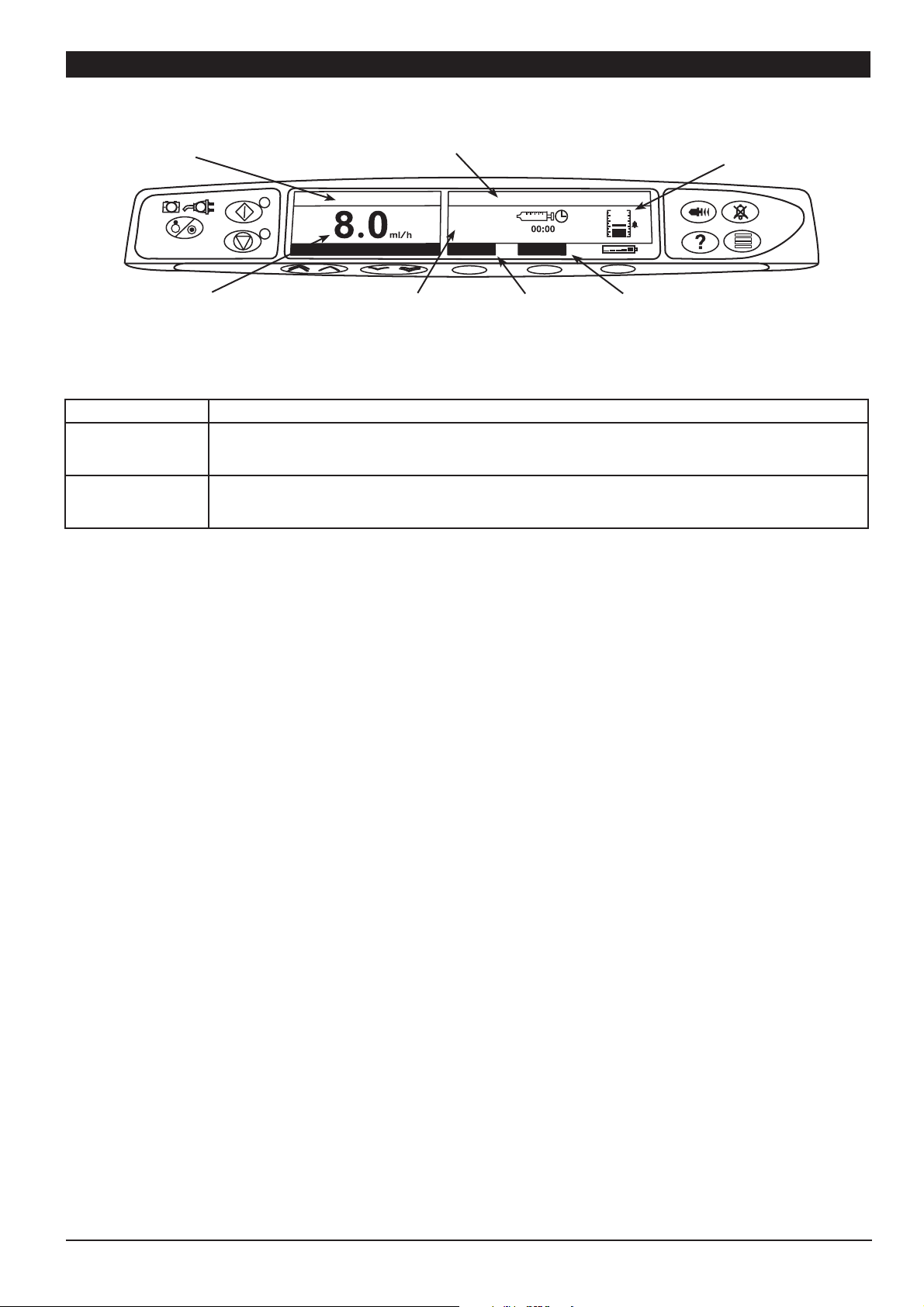
Main Display Features
Pump
Status
Infusion
Rate
Screen Icons:
Symbol Description
TIME REMAINING DISPLAY icon - Indicates time before syringe will require replacing.
l
N
BATTERY icon - Indicates battery charge level to highlight when the battery will require recharging.
Syringe type fitted /
Drug name
ON HOLD
+ ADJUST -
Volume
Infused
VOLUME
0.0
VOLUME
IVAC 50
ml
Volume Infused
Option
Pressure
Information
VTBI
VTBI
Option
1000DF00002 Iss. 2
6/32
Page 8

m
n
o
G
H
Operating Precautions
Disposable Syringes and Extension Sets
• This Alaris® GH Syringe Pump has been calibrated for use with single-use disposable syringes. To ensure
correct and accurate operation, only use 3 piece Luer-Lock versions of the syringe make specified on
the pump or described in this manual. Use of non-specified syringes or extension sets may impair the
operation of the pump and the accuracy of the infusion.
• Uncontrolled flow or syphoning may result if the syringe is located incorrectly in the pump, or if it is
removed from the pump before the extension set is properly isolated from the patient. Isolation may
include closing a tap in the patient line or activating a flow stop clamp.
• Secure the extension set to the pump using the extension set hook at the rear of the pump. This provides
protection against accidental dislodging of the syringe from the pump.
• When combining several apparatus and/or instruments with extension sets and other tubing, for example
via a 3-way tap, the performance of the pump may be impacted and should be monitored closely.
Mounting the Pump
• The pump must be mounted within 1.0m above or below the patient’s heart. The most accurate pressure
monitoring in the extension set is achieved when the pump is positioned close to the patients heart
level.
I
• Do not mount the pump in a vertical position with the syringe pointing upwards as this could lead to
an infusion of air which may be in the syringe. To protect against the introduction of air the user should
regularly monitor the progress of the infusion, syringe, extension line and patient connections and follow
the priming procedure specified herein.
Operating Environment
• When using any infusion pump in conjunction with other pumps or devices requiring vascular access,
extra care is advised. Adverse delivery of medication or fluids can be caused by the substantial variation in
pressures created within the local vascular system by such pumps. Typical examples of those pumps are
used during dialysis, bypass or cardiac assist applications.
• This pump is suitable for use in Hospital and clinical environments other than domestic establishments
and those directly connected to the public single phase AC mains power supply network that supplies
buildings used for domestic purposes. However, it may be used in domestic establishments under
the supervision of Medical professionals with additional necessary appropriate measures. (Consult
Technical Service Manual, appropriately trained technical personnel or Cardinal Health for further
information).
• This pump is not intended to be used in the presence of a flammable anaesthetic mixture with air or
oxygen or nitrous oxide.
Operating Pressure
• This is a positive pressure pump designed to achieve very accurate fluid administration by automatically
compensating for resistance encountered in the infusion system.
J
• The pumping pressure alarm system is not designed to provide protection against, or detection of, IV
complications which can occur.
Alarm Conditions
• Several alarm conditions detected by this pump will stop the infusion and generate visual and audible
alarms. Users must perform regular checks to ensure that the infusion is progressing correctly and no
alarms are operating.
1000DF00002 Iss. 2
7/32
Page 9

M
K
B
Operating Precautions (continued)
Electromagnetic Compatibility & Interference
• This pump is protected against the effects of external interference, including high energy radio frequency
emissions, magnetic fields and electrostatic discharge (for example, as generated by electrosurgical and
cauterising equipment, large motors, portable radios, cellular telephones etc.) and is designed to remain
safe when unreasonable levels of interference are encountered.
• This pump is a CISPR 11 Group 1 Class A device and uses RF energy only for its internal function in the normal
product offering. Therefore, its RF emissions are very low and are not likely to cause any interference with
the nearby electronic equipment. However, this pump emits a certain level of electromagnetic radiation
which is within the levels specified by IEC/EN60601-1-2 and IEC/EN60601-2-24. If the pump interacts with
other equipment, measures should be taken to minimise the effects, for instance by repositioning or
relocation.
• In some circumstances the pump may be affected by an electrostatic discharge through air at levels close
to or above 15kv; or by radio frequency radiation close to or above 10v/m. If the pump is affected by
this external interference the pump will remain in a safe mode; the pump will duly stop the infusion and
alert the user by generating a combination of visual and audible alarms. Should any encountered alarm
condition persist even after user intervention, it is recommended to replace that particular pump and
quarantine the pump for the attention of appropriately trained technical personnel. (Consult Technical
Service Manual for further information).
Hazards
• An explosion hazard exists if the pump is used in the presence of flammable anaesthetics. Exercise care to
locate the pump away from any such hazardous sources.
A
V
L
• Dangerous Voltage: An electrical shock hazard exists if the pump’s casing is opened or removed. Refer all
servicing to qualified service personnel.
• When connected to an external power source, a three-wire (Live, Neutral, Earth) supply must be used. If the
integrity of the external protective conductor in the installation or its arrangement is in doubt, the pump
should be operated from the battery.
• Do not open the RS232/ Nurse Call protective covering when not in use. Electrostatic discharge
(ESD) precautions are required when connecting RS232/ Nurse Call. Touching the pins of the
connectors may result in ESD protection failure. It is recommended that all actions must be taken by
appropriately trained personnel.
• If this pump is dropped, subjected to excessive moisture, fluid spillage, humidity or high temperature, or
otherwise suspected to have been damaged, remove it from service for inspection by a qualified service
engineer. When transporting or storing the pump, use original packaging where possible, and adhere
to temperature, humidity and pressure ranges stated in the Specifications section and on the outer
packaging.
Latex Content
• The Alaris® GH Syringe Pump does not contain any Latex.
1000DF00002 Iss. 2
8/32
Page 10

Getting Started
Initial Set-up
Before operating the pump read this Directions For Use manual carefully.
A
1. Check that the pump is complete, undamaged and that the voltage rating specified on the label is compatible with your AC power
supply.
2. Items supplied are:
Alaris® GH Syringe Pump
User Support CD (Directions For Use)
AC Power Cable (as requested)
Protective Packaging
3. Connect the pump to the AC power supply for at least 2½ hours to ensure that the internal battery is charged (verify that the S is
lit).
Language Selection
1. On initial start-up the pump will display the Select Language screen.
2. Select the required language from the list displayed using the
3. Press the OK softkey to confirm your selection.
f keys.
A
The pump will automatically operate from its internal battery if the pump is switched on without being connected to
the AC power supply.
Should the pump fail to perform correctly, replace in its original protective packaging, where possible and contact a
qualified service engineer for investigation.
1000DF00002 Iss. 2
9/32
Page 11
*
*
Getting Started (continued)
Do not mount the pump with the AC power inlet or the syringe pointing upwards. This could affect the electrical
safety in the event of a fluid spill or lead to the infusion of air which may be in the syringe.
A
Pole Clamp Installation
The pole clamp is fitted to the rear of the pump and will provide secure fixing to vertical I.V. poles of a diameter between 15 and 40 mm.
Recessed area
1. Pull the folded pole clamp towards you and unscrew the clamp to
leave enough room for the size of the pole.
2. Place pump around pole and tighten screw until the clamp is
secured to the pole.
Ensure the pole clamp is folded away and stored
within the recessed area at the rear of the
A
pump before connecting to a Docking Station/
Workstation* or when not in use.
Never mount the pump such that the IV infusion
stand becomes top heavy or unstable.
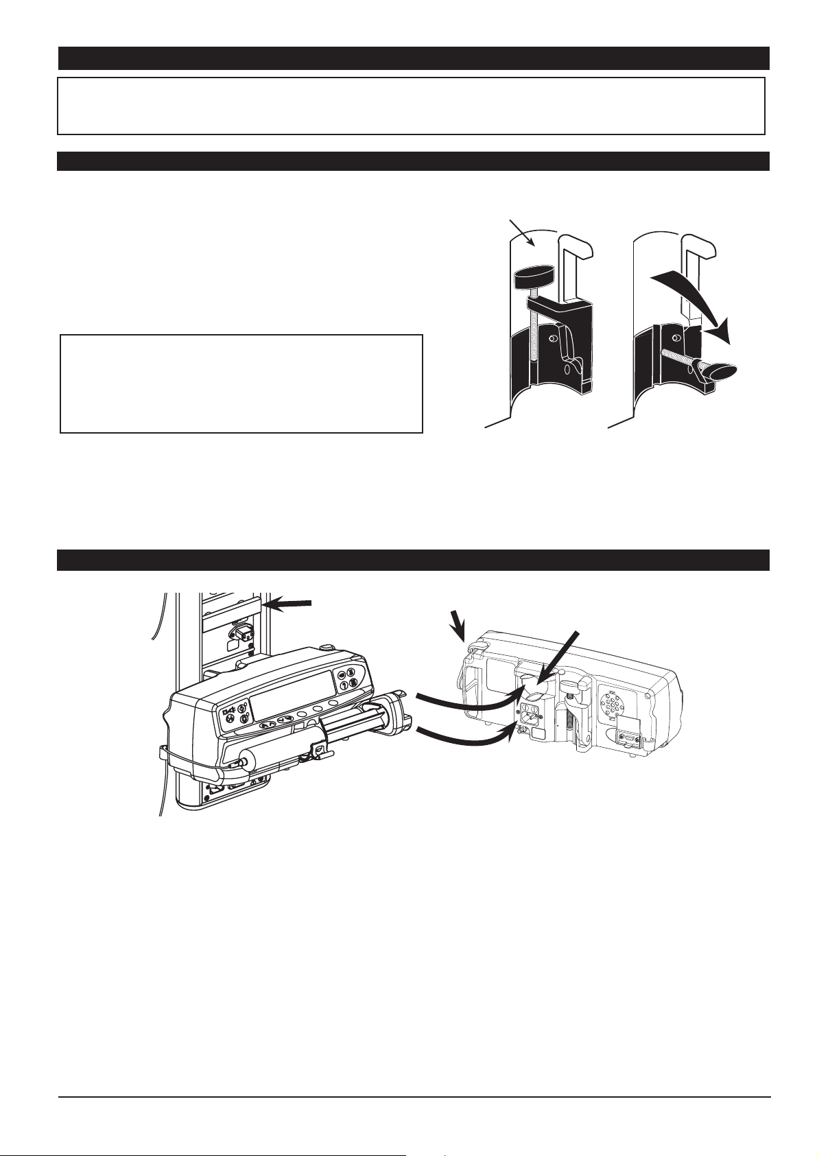
Docking Station/ Workstation* or Equipment Rail Installation
Rectangular bar
The rotating cam can be fitted to the rectangular bar on the Docking Station/ Workstation* or the equipment rail measuring 10 by 25 mm.
1. Align the rotating cam on the rear of the pump with the rectangular bar on the Docking Station/ Workstation* or the equipment rail.
2. Hold the pump horizontally, push the pump firmly onto the rectangular bar or equipment rail.
Ensure that the pump 'clicks' securely into position onto the bar.
3. To release, push the release lever and pull the pump forwards.
Release lever (push to release)
Rotating cam
1000DF00002 Iss. 2
* Alaris® DS Docking Station, Asena® IDS Docking Station, and Alaris® Gateway Workstation.
10/32
Page 12

Getting Started (continued)
Loading a Syringe
Only use a syringe of the type stated on the pump or in this manual. Using an incorrect syringe could adversely affect
the accuracy of the infusion and the performance of the pump.
A
Place the pump on a stable horizontal surface or secure as described above.
Prepare, load and prime the single-use disposable syringe and extension set using standard aseptic techniques.
1. Squeeze the finger grips together on the plunger holder and slide the mechanism to the right. Pull the syringe clamp forward and
down.
When initially loading the syringe, allow for the volume of fluid contained in the extension set and retained in the
syringe at the end of infusion as this “dead-space” will not be infused.
To ensure the syringe is loaded correctly, place the barrel flange in the space between the syringe clamp and the
syringe flange clamp. This is correct if the syringe remains in position before the syringe clamp is closed.
A
2. Insert the syringe ensuring that the barrel flange is located in the slots on the syringe flange clamp.
3. Lift the syringe clamp until it locks against the syringe barrel.
4. Squeeze the finger grips on the plunger holder and slide the mechanism to the left until it reaches the plunger end.
5. Release the finger grips. Ensure that the plunger grippers are securing the plunger in place and the finger grip returns to its original
position.
Secure the extension set using the extension set hook at the rear of the pump. This provides protection against
accidental dislodging of the syringe from the pump.
A
Ensure that both plunger grippers are fully locked onto the plunger flange and the upper finger grip has returned to
its original position.
Syringe
Barrel
Barrel
Flange
Plunger
Grippers
Syringe
Clamp
Plunger
Flange
Plunger
Finger
Grips
Plunger
Holder
Syringe Flange
Clamp
1000DF00002 Iss. 2
11/32
Page 13

Getting Started (Continued)
Starting the Pump
1. Connect the pump to an AC power supply using the AC power cable.
Press the
The pump will run a short self-test. Ensure that two beeps are activated during this test.
Check the display test pattern and ensure that no rows are missing.
Check that the displayed time and date are correct.
Note: A warning - REPAIRING LOGS, may be displayed if event log information was not completely stored at the previous power down.
This is for information only, the pump will continue to power up as normal.
2. CLEAR SETUP? Answering NO will retain all previous rate and volume settings. YES will automatically reset the rate and volume
settings to zero.
3. LOAD SYRINGE - Load the syringe according to the procedure in this manual.
4. CONFIRM SYRINGE - Check that the syringe type and size being used matches the display. If required, the make of syringe can be
changed by pressing the TYPE button. Press CONFIRM when the correct type and size are shown.
If the PURGE SYRINGE option has been enabled then the prompt to purge screen is displayed and the set can be purged as
required.
a button.
5. INFUSION RATE - Check the rate shown if old patient data has been retained and change the rate if necessary using the
keys.
6. PURGE (if required) - Press the
extension line is complete. Release the softkey. The volume used during purging will be displayed.
7. CONNECT TO PATIENT - Connect the extension set to the patient access device.
8. START - Press b to commence operation. INFUSING will be displayed. The AMBER STOP light will be replaced by the flashing GREEN
START light to indicate that the pump is in operation.
9. STOP - Press
h to halt the operation. ON HOLD will be displayed. The amber light will replace the green light.
i button and then press and hold the PURGE softkey until fluid flows and the purging of the syringe
f
1000DF00002 Iss. 2
12/32
Page 14

Basic Features
Purge
The i button allows the delivery of a limited volume of fluid in order to purge the extension set prior to being connected to a patient or
after changing a syringe.
1. Press the
2. Press and hold the PURGE softkey until fluid flows and the purging of the IV infusion set is complete. The volume used during purging
will be displayed, but it is not added to the volume infused.
3. When purging is complete release the PURGE softkey. Press the QUIT softkey to exit back to the main display.
i button when the pump is not infusing. Ensure that the extension set is not connected to the patient.
The pump will not purge if the rate lock has been enabled. During PURGE the pressure limit alarms are temporarily
increased to their maximum level.
A
Bolus Infusion
Bolus - Administering a controlled volume of fl uid or drug at an increased rate for diagnostic or therapeutic purposes. The pump should
always be infusing and always attached to the patient. (Drugs given by an IV bolus could achieve immediate and high drug
concentration levels.)
Bolus can be used at the start of an infusion or during an infusion.
The bolus feature can be confi gured to:
a) BOLUS Disabled
b) BOLUS Enabled i) Hands On only
ii) Hands On and Hands Free
BOLUS Disabled
If confi gured to Disabled, pressing the
i button will have no eff ect and the pump will continue to infuse at the set rate.
A Hands On bolus and Hands Free bolus cannot be administered if the "RATE LOCK" is active.
During BOLUS the pressure limit alarm is temporarily increased to the maximum level.
A
BOLUS Enabled - Hands On
In "Hands on" Bolus, press and hold the (fl ashing) BOLUS soft key to deliver the required bolus. The bolus rate can be adjusted. The bolus
volume is limited in the confi guration.
1. During infusion press the
2. Use the
3. To deliver the bolus press and hold the BOLUS softkey. During the bolus, the volume being infused is displayed. When the desired bolus
volume has been delivered or the bolus volume limit is reached, release the softkey. The bolus volume is added to the total volume
infused.
BOLUS Enabled - Hands On and Hands Free
The "Hands Free" Bolus is delivered with a single press of the (fl ashing) BOLUS soft key. On intial use the bolus rate and bolus volume are
at default values and can be changed. On subsequent uses, the bolus rate and bolus volume will remain as per previously set and can be
changed as required. Following CLEAR SETUP, the default bolus rate is determined via the confi guration and the default bolus volume is
0.1ml.
1. During infusion press the
2. Press the YES softkey to go to " Hands Free" selection bolus screen, press the HANDS ON softkey for " Hands On" bolus (see section
above).
3. Use the
(150/300/600/900/1200ml/h). Note: Rate may be restricted by the syringe size and the CAP BOLUS RATE.
4. Press the fl ashing BOLUS softkey once to begin the delivery of the preset bolus. The display will show the bolus being delivered, the
bolus counting down and revert to main infusion display upon completion of the bolus.
5. To terminate a bolus being delivered press STOP softkey. This will stop the bolus and continue infusing at the set rate. Press the
button to stop the bolus delivery and place the pump on hold.
6. If the bolus volume reaches the set bolus volume limit the bolus will stop and the pump will revert to infuse at the set infusion rate and
continue infusing.
f keys to adjust the bolus rate if required.
f keys to set the bolus volume/dose required; If necessary press the RATE softkey to adjust the bolus delivery rate
i button once to display the bolus screen.
i button to display the "Hands Free" bolus selection screen.
h
If the " Hands Free" bolus option is active, then this feature will be cancelled following any interruption in delivery, e.g.
occlusion, even if the bolus delivery is incomplete.
A
Manual Bolus
The "Manual Bolus" is delivered by moving the plunger drive mechanism forward while the pump is infusing. This method of delivering a
bolus is not recommended as best clinical practice.
The syringe must be confi rmed and the plunger mechanism has to move from an engaged position to disengage and then re-engage
position.
A minimum travel of 1mm (leadscrew pitch) must be detected to register.
If the volume to be infused ( VTBI) is reached during a bolus, the VTBI complete alarm will sound. Press
alarm or CANCEL to acknowledge the alarm. See 'VTBI' section for more details on VTBI operation.
1000DF00002 Iss. 2
13/32
c to silence the
Page 15

Basic Features (Continued)
Pressure Level
1. To check and adjust the pressure level press the e button. A bar graph will be displayed showing the pressure alarm level and the
current pressure level.
2. Press the
3. Press OK to exit the screen.
f keys to increase or decrease the alarm level. The new level will be indicated on the display.
The interpretation of pressure readings and occlusion alarms are the responsibility of the clinician depending on the
specific application.
A
Rate Titration
If Rate Titration is enabled the rate can be adjusted while infusing:
1. Select the new rate using the
The message < START TO CONFIRM > will flash on screen and pump continues to infuse at the original rate.
2. Press the
If Rate Titration is disabled the rate can only be adjusted whilst on hold:
1. Press the
2. Select the new rate using the
3. Press the
This option allows a specific volume to be infused to be set. Rate at the end of this VTBI can also be set, selecting from stop, KVO, or
continuous infusion at the set rate.
1. Press the VTBI softkey to select the volume to be infused option.
2. Enter the volume to be infused using the
3. Select the rate at the end of the VTBI using the
4. Press the OK softkey to enter the rate and exit the VTBI menu.
b button to confirm the new infusion rate and start infusing at the new rate.
h
button to put the pump on hold.
b button to start infusing at the new rate.
f keys.
f keys.
Volume to be Infused ( VTBI)
f keys and press the OK softkey.
f keys to scroll through the on-screen choices. The default is stop.
Clear Volume
This option enables the volume infused to be cleared.
1. Press the VOLUME softkey to display the CLEAR VOLUME option.
2. Press the YES softkey to clear the volume. Press the NO softkey to retain the volume.
Selecting YES resets the volume infused in the 24H LOG option.
Rate Lock
If Rate Lock is enabled, when the infusion rate has been set and the infusion started (or following a bolus infusion) the rate lock prompt
will appear on the main display.
To select the rate lock function press the YES softkey. Press the NO softkey if the rate lock is not required.
When rate lock is enabled, the following are unavailable:
Changing the infusion rate / titration
Bolus / purge
Switching the pump off
VTBI over time infusions.
To disable the rate lock if selected:
1. Press the
2. Select the UNLOCK RATE option using the
To enable the rate lock if not selected:
1. Press the
2. Select RATE LOCK and press the OK softkey.
d button to access the options menu.
f keys and press the OK softkey.
d button to access the options menu.
1000DF00002 Iss. 2
14/32
Page 16

Basic Features (Continued)
? Set VTBI over Time
This option allows a specific VTBI and delivery time to be set. The rate necessary to deliver the required volume within the specified time
is calculated and displayed.
1. Stop the infusion. Press the
2. Select the SET VTBI OVER TIME option using the
3. Adjust the volume to be infused using the
4. Enter the time over which the volume is to be infused. The infusion rate will automatically be calculated. Press the OK softkey to enter
the value.
5. Select the rate at VTBI end from the list using the
d button to access the options menu.
f keys and press the OK softkey.
f keys. When the desired volume has been reached press the OK softkey.
f keys and press the OK softkey. The default is STOP.
? 24 Hour Log
This option allows the 24 hour log of volume infused to be reviewed.
1. Press the
2. Select the 24H LOG option using the
The display shows the hourly volume infused. The volume infused shown in brackets is the total volume infused since the volume was
last cleared. See example below:
07:48 - 08:00 4.34ml (4.34ml)
08:00 - 09:00 2.10ml (6.44ml)
09:00 - 10:00 2.10ml (8.54ml)
VOLUME CLEARED
3. Press the QUIT softkey to exit the log.
d button to access the options menu.
f keys and press the OK softkey.
? Event Log
This option allows the event log to be reviewed. It can be enabled/disabled.
1. Press the
2. Select the EVENT LOG option using the
3. Scroll through the log using the
d button to access the options menu.
f keys and press the OK softkey.
f keys. Press the QUIT softkey to exit the log.
? Drug Name
This option enables the selection of a drug from the drug names set up in configuration.
1. Press the
2. Select DRUG NAME. Note: Selecting CLEAR DRUG NAME will clear the drug name.
3. Press the OK softkey to confirm the drug name or press the QUIT softkey to exit the option.
d button to access the options menu.
1000DF00002 Iss. 2
15/32
Page 17

Alarms and Warnings
Alarms are indicated by a combination of an audible alarm, flashing alarm indicator and a descriptive message in the display.
1. First press the
to cancel the alarm message.
2. If the infusion has stopped, rectify the cause of the alarm then press the
c button to silence the alarm for a maximum of 2 minutes*, then check the display for an alarm message. Press CANCEL
b button to resume the infusion.
Display Description and Troubleshooting Guide
DRIVE DISENGAGED
OCCLUSION
CHECK SYRINGE
BATTERY LOW
BATTERY EMPTY
NEAR END OF INFUSION
END OF INFUSION
The drive system has been disengaged during operation. Check the finger grips and the position
of the syringe.
Excessive pressure measured at the syringe plunger exceeding the alarm limit. Identify and
remove the cause of the blockage in the drive, syringe, or administration system before restarting
the infusion.
Incorrect size of syringe has been fitted, the syringe has not been positioned correctly or has
been disturbed during operation. Check the syringe location and the position.
Battery charge low with 30 minutes operation remaining. Battery indicator will flash and after 30
minutes a continuous audible alarm will indicate that the battery is exhausted. Reconnect to the
AC power supply to continue operation and charge the internal battery.
The internal battery is exhausted. Connect the pump to the AC power supply.
The pump is nearing the end of the infusion.This value can be configured.
The pump has reached the end of the infusion. A pre-set volume will remain in the syringe to
minimise the risk of the infusion of air bubbles into the set. This value can be configured.
TITRATION NOT CONFIRMED The infusion rate has been changed, but has not been confirmed and 2 minutes* has
expired without any operation. Press the c button to silence the alarm, then press the CANCEL
softkey to clear this message and silence the alarm. Check infusion rate and confirm by pressing
the
b button or press the h button to revert to the previous rate. Press the b button to start
infusion. (This alarm only occurs if rate titration is enabled).
VTBI DONE
AC POWER FAIL
The pre-set Volume To Be Infused is complete.
AC Power has been disconnected and the pump is operating on battery power, if this occurs
when the pump is infusing the message "INFUSION CONTINUES" will be displayed. Reconnect
AC power supply or press the
The alarm will automatically cancel if the AC power supply is reconnected.
c button to silence the alarm and continue with battery operation.
Error Code and Message
ATTENTION (with “3 Beeps”)
The alarm system has detected an internal malfunction. Note the malfunction code. Remove
pump from service for examination by a qualified service engineer.
Three beeps will sound if the pump has been left ON for more than 2 minutes* (referred to as
CALLBACK in the log) without starting the operation. Press the
for a further 2 minutes*. Alternatively press and hold down the
in succession, this will put the warning alarm on standby for 15 minutes.
Alarm Indicator Colour Alarms indicated
AMBER
RED
AC POWER FAIL; NEAR END OF INFUSION; VTBI DONE (KVO or CONTINUE), ATTENTION; TITRATION
NOT CONFIRMED; BATTERY LOW.
All others.
c button to silence the alarm
c button and wait for 3 beeps
*Configurable option.
1000DF00002 Iss. 2
16/32
Page 18

Configured Options
This menu comprises a list of options which are configurable by the user.
1. Turn the pump OFF.
2. Whilst holding down the
3. The main display will show 000. Enter the access code for Configured Options using the f keys, pressing NEXT to move through
the digits. A full list of access codes can be found in the Technical Service Manual.
4. When the complete code shows on screen, press OK to enter. The Configured Options menu will be displayed.
1. Select GENERAL OPTIONS from the menu using the
2. Select the option you wish to enable/disable or adjust and press the MODIFY softkey.
3. When all the desired modifications have been carried out press the QUIT softkey.
4. Either select the next configuration option from the menu or turn the pump OFF, returning it to operation as required.
NURSE CALL FITTED Enables Nurse Call (hardware option).
NURSE CALL INVERT When enabled, the nurse call output is inverted.
RS232 SELECTED Sets the pump's communications to use RS232 (hardware option).
NEOI WARNING Sets the Near End Of Infusion warning time, as time left to End Of Infusion.
EOI POINT Sets the End Of Infusion point.
KVO AT EOI When enabled the pump will switch to running at the KVO rate when EOI is reached.
KVO RATE Sets the Keep Vein Open (KVO) rate at which the pump will operate if KVO at EOI is enabled.
BACK OFF When enabled the motor will reverse to relieve line pressure when an occlusion occurs.
AUTO SAVE When disabled the infusion information is cleared on power up.
RATE LOCK When enabled the rate can be locked to prevent unwanted changes of the set infusion rate.
QUIET MODE When enabled the button beeps are muted.
AC FAIL When enabled the AC Power Failure Alarm will sound if the AC power is disconnected.
RATE TITRATION When enabled the rate can be changed whilst the pump is infusing.
PRESSURE DISPLAY Enables / disables the Pressure Icon on the main display.
CAP PRESSURE Sets the maximum pressure value.
PRESSURE DEFAULT Sets the default occlusion alarm level.
CAP RATE Sets the maximum value for infusion rate.
PURGE RATE Sets the purge rate.
PURGE VOLUME LIMIT Sets the maximum permissible purge volume.
PURGE SYRINGE Prompt to purge syringe after confi rmation.
BOLUS Enables / disables the bolus feature.
DEFAULT BOLUS Sets the default bolus rate.
CAP BOLUS RATE Sets the maximum value for bolus rate.
BOLUS VOL LIMIT Sets the maximum permissible bolus volume.
MANUAL BOLUS Volume infused will be increased if plunger is manually moved in and syringe remains confi rmed.
CALL BACK TIME Adjusts the time for the pump to sound the call back alarm.
VTBI CLEAR RATE Rate will be set to zero when VTBI has been set-up with stop as the end rate.
EVENT LOG DISPLAY Enables / disables the event log.
BATTERY ICON Enables / disables the Battery Icon on the main display.
AUDIO VOLUME Sets the alarm volume of the pump at high, medium or low.
AUTO NIGHT MODE Backlight dims between hours 21:00 and 06:00.
b button turn the pump ON.
General Options
f keys and press the OK softkey.
1000DF00002 Iss. 2
17/32
Page 19

Configured Options (Continued)
Drug Set-up
This option is used to set up a list of drug names.
1. Select DRUG LIBRARY from the menu using the
2. Select the required drug and press the OK softkey.
3. In order to use a drug it must be enabled. Press the YES softkey to enable the selected drug.
4. To add or change a drug name use the
the next position. On completion press the OK softkey.
5. When the set-up is complete turn the pump OFF, then return the pump into operation as required. Alternatively, select the next
configuration option from the menu.
1. Select CLOCK SET from the Configured Options menu using the f keys and press the OK softkey.
2. Use the
3. When the correct time and date are displayed press the OK softkey to return to the Configured Options menu.
This option allows the user to programme in the name of the hospital, ward or department. This will appear during the power-up display
sequence.
1. Select HOSPITAL NAME from the Configured Options menu using the
2. Use the keys to adjust the character displayed, pressing NEXT to access the next position.
3. When the correct name is displayed press OK to return to the Configured Options menu.
f keys to adjust the date displayed, pressing the NEXT softkey to access the next field.
f keys to scroll through the alphabet, pressing NEXT to select a letter and move on to
f keys and press the OK softkey.
Clock Set
Hospital Name
f keys and press the OK softkey.
Enable Syringes
This option is used to pre-configure the type and size of syringe permitted for use on the pump. Select all possible syringes which may be
used and disable any that should not be used.
1. Select ENABLE SYRINGES from the Configured Options menu using the
2. Use the
within the brand.
3. When all modifications are complete press OK to return to the Configured Options menu.
f keys to scroll through the list of syringes, pressing MODIFY to enable/disable a syringe brand and individual models
f keys and press the OK softkey.
Language
This option is used to set the language of messages shown on the pump display.
1. Select LANGUAGE from the Configured Options menu using the
2. Use the
3. When the desired language has been selected press SELECT softkey to return to the Configured Options menu.
f keys to select the language.
f keys and press the OK softkey.
Contrast
This option is used to set the contrast on the pump display.
1. Select CONTRAST from the Configured Options menu using the
2. Use the
3. When the desired value has been reached press the OK softkey to return to the Configured Options menu.
f keys to select a contrast ratio value. The contrast of the display will change when scrolling through the numbers.
f keys and press the OK softkey.
1000DF00002 Iss. 2
18/32
Page 20

Alaris® GH Syringe Pump Configured Options Record
General Options Enter the pump-specific information for your records on a copy of this page.
Option Default Range Setting
Software Version 1.5.10 & 2.0.0
NURSE CALL FITTED Disabled Disabled Enabled/Disabled
NURSE CALL INVERT Disabled Disabled Enabled/Disabled
RS232 SELECTED Disabled Disabled Enabled/Disabled
NEOI WARNING 1min 5mins 1min - 15mins
EOI POINT 1.0% 1.0% 0.1% - 5% of syringe volume
KVO AT EOI Enabled Enabled Enabled/Disabled
KVO RATE 1.0ml/h 1.0ml/h 0.1ml/h - 2.5ml/h
BACK OFF Disabled Enabled Enabled/Disabled
AUTO SAVE Enabled Enabled Enabled/Disabled
RATE LOCK Disabled Disabled Enabled/Disabled
QUIET MODE Disabled Disabled Enabled/Disabled
AC FAIL Enabled Enabled Enabled/Disabled
RATE TITRATION Disabled Disabled Enabled/Disabled
PRESSURE DISPLAY Disabled Enabled Enabled/Disabled
CAP PRESSURE L10 L0 - L10 (50mmHg - 1000mmHg)
PRESSURE DEFAULT L3 L3 L0 - L10 (50mmHg - 1000mmHg)
CAP RATE Max infusion rate 1200ml/h 1.0ml/h - 1200ml/h
PURGE RATE 200ml/h 200ml/h 100ml/h - 500ml/h
PURGE VOLUME LIMIT 2.0ml 2.0ml 0.5ml - 5.0ml
PURGE SYRINGE Disabled Enabled/Disabled
BOLUS Enabled Enabled Enabled/Disabled
DEFAULT BOLUS Max bolus rate 500ml/h 10ml/h - 1200ml/h
CAP BOLUS RATE Max bolus rate 1200ml/h 10ml/h - 1200ml/h
BOLUS VOL LIMIT 5.0ml 5.0ml 0.5ml (0.1ml)* - 25.0ml
MANUAL BOLUS Disabled Enabled/Disabled
CALL BACK TIME 2mins 0.1mins - 15mins
VTBI CLEAR RATE Disabled Enabled/Disabled
EVENT LOG DISPLAY Disabled Enabled Enabled/Disabled
BATTERY ICON Enabled Enabled/Disabled
AUDIO VOLUME Medium Medium Low, medium, high
AUTO NIGHT MODE Enabled Enabled Enabled/Disabled
1.9.x &
2.3.x and above
* For software versions 1.9.x & 2.3.x and above
Syringes Enabled Drug Names
Make Size(s) 1 7
28
39
410
511
612
Hospital Name Serial No. Software Version
Approved by Confi gured by
Date Date
1000DF00002 Iss. 2
19/32
Page 21

Specifications
Infusion Specifications -
Maximum infusion rate can be set as part of the configuration.
0.1ml/h - 150ml/h 5ml syringes
0.1ml/h - 300ml/h 10ml syringes
0.1ml/h - 600ml/h 20ml syringes
0.1ml/h - 900ml/h 30ml syringes
0.1ml/h - 1200ml/h 50ml syringes
The Volume Infused range is 0.0ml - 9990ml.
Bolus Specifications -
Maximum Bolus rates can be set as part of the configuration. Bolus
rates are user adjustable, in increments of 10ml/h.
10 ml/h - 150ml/h 5ml syringes
10 ml/h - 300ml/h 10ml syringes
10 ml/h - 600ml/h 20ml syringes
10 ml/h - 900ml/h 30ml syringes
10 ml/h - 1200ml/h 50ml syringes
The bolus volume limit can be set as part of the configuration.
Minimum: 0.5ml (0.1ml - v2.3.x & above or v1.9.x);
Maximum 25.0ml
Increments of 0.1ml; default 5.0ml
During BOLUS the pressure limit alarms are temporarily increased to
their maximum level.
Critical Volume -
The bolus which can occur in the event of a single internal fault
condition with a 50 ml syringe is :
Maximum Overinfusion - 0.5ml
Purge Specifications -
The purge rate is limited to the maximum rate for the syringe and can
be set as part of the configuration.
100ml/h - 500ml/h.
The purge volume range is 0.5ml - 5ml.
During PURGE the pressure limit alarms are temporarily increased to
their maximum level.
Keep Vein Open (KVO) Rate -
0.1 ml/h - 2.5ml/h.
End Of Syringe Rate -
Stop, KVO (0.1ml/h to 2.5ml/h), or set rate if lower than KVO.
Volume To Be Infused ( VTBI) -
0.1ml - 100ml (0.1ml - 1000ml - v2.3.x & above or v1.9.x),
1min - 24h
VTBI Complete Rate -
Stop, KVO (0.1ml/h to 2.5ml/h), set rate if lower than KVO or continue
at set rate.
Near End Of Infusion Alarm -
1min - 15min to end of infusion, or 10% of syringe volume, whichever
is smaller.
End Of Infusion (EOI) Alarm -
0.1% - 5% of syringe volume
Electrical Classification -
Class I product. Continuous Mode Operation, Transportable
Maximum Pumping Pressure Limit -
Highest alarm level 1000mmHg (nominal at L-10)
Occlusion Accuracy (% of full scale)* -
Pressure mmHg
L-0 L-3 L-5 L-10
50 mmHg 300 mmHg 500 mmHg 1000 mmHg
Temp.
23°C ±18% ±21% ±23% ±28%
approx. approx. approx. approx.
* - Using most common 50ml syringes under normal conditions
(95% confidence / 95% of pumps).
System Accuracy -
Volumetric Mean +/- 2% (nominal).
Derating
-
Temperature +/- 0.5% (5 - 40ºC)
High Rates +/-2.0% (rates > syringe volume/h eg.
>50ml/h in a 50ml syringe.)
Important: System accuracy is +/-2% typical by volume as measured
using the trumpet curve test method defined in IEC/EN60601-2-24
at rates of 1.0ml/h (23ºC) and above when the pump is used with
the recommended syringes. Differences in factors such as size and
plunger force in compatible syringes can cause variations in accuracy
and trumpet curves. See also trumpet curves section in this manual.
Battery Specifications -
Rechargeable sealed NiMH. Automatically charges when the pump is
connected to AC power.
Battery life is typically 4h from fully charged @ 5.0ml/h & 20ºC under
normal conditions. Charging takes 2½ hours from discharge to 90%
charge.
Memory Retention -
The electronic memory of the pump will be retained for more than 6
months when not powered up.
Fuse Type -
2 x T 1.25A, slow blowing.
AC Power Supply -
115 - 230VAC, 50 - 60Hz, 20VA (nominal).
Dimensions -
310 mm (w) x 121 mm (h) x 200 mm (d). Weight: 2.7 kg (excluding
power cable).
Protection against fluid ingress -
IPX1 - Protected against vertically falling drops of water.
Alarm Conditions -
Drive Disengaged Occlusion
Check Syringe Battery Low / Battery Empty
Near End Of Infusion End of Infusion
VTBI Done AC Power Fail
Internal Malfunction Attention (Nurse Callback)
Titration not confirmed
Environmental Specifications -
Operating Temperature +5°C - +40°C
Operating Relative Humidity 20% - 90%
Operating Atmospheric Pressure 700hPa - 1060hPa
Transport & Strorage Temperature -30°C - +50°C
Transport & Strorage Relative Humidity 10% - 95%
Transport & Strorage Atmospheric Pressure 500hPa - 1060hPa
Electrical/Mechanical Safety -
Complies with IEC/EN60601-1 and IEC/EN60601-2-24.
EMC -
Complies with IEC/EN60601-1-2
and IEC/EN60601-2-24.
1000DF00002 Iss. 2
20/32
Page 22

Compatible Syringes
The pump is calibrated and labelled for use with single-use disposable Luer-lock syringes. Only use the size and type of syringe specified
on the pump display. The full list of permitted syringe models is dependent on the software version of the pump.
5ml 10ml 20ml 30ml 50ml
IVAC®
AstraZeneca
B Braun Omnifi x
B Braun Perfusor
BD Perfusor
BD Plastipak
BD Precise
Codan
Codan Perfusion
Fresenius Injectomat
Monoject**
Nipro
Pentaferte
Rapiject*
Terumo
* - The Rapiject 50ml syringe is a specialised syringe with a large diameter barrel. To provide protection against accidental dislodging always
ensure the infusion line is secured using the infusion set hook - see Loading a Syringe section.
** - TYCO / Healthcare KENDALL - MONOJECT.
The Alaris® DS
Docking Station
Associated Products
The Asena® IDS
Docking Station
The Alaris® Gateway Workstation
1000DF00002 Iss. 2
21/32
Page 23

Compatible Extension Sets
The pump uses standard, single-use, disposable extension sets and syringes with Luer-lock connectors. The user is responsible for verifying
the suitability of a product used, if it is not recommended by Cardinal Health.
Standard Sets
G40015 Standard PVC Syringe Extension Set (150 cm).
Priming Volume: 2.6ml
G40020B Standard PVC Syringe Extension Set (200 cm).
Priming Volume: 1.5ml
G402EP Extension set, luer lock connectors. Kink resistant DEHP free PVC yellow striped tubing. Bore 1mm. Length 200cm.
Priming volume 1.6ml.
Light Protected Sets
G40215 Amber PVC Syringe Extension Set (150 cm).
Priming Volume: 1.2ml
G40320 White PVC Syringe Extension Set (200 cm).
Priming Volume: 3.6ml
Low Sorbing Sets
G40615 Polyethylene Syringe Extension Set (150 cm).
Priming Volume: 1.5ml
G40620 Polyethylene Syringe Extension Set (200 cm).
Priming Volume: 1.6ml
G40720 Polyethylene Lined Syringe Extension Set with clamp. (200 cm).
Priming Volume: 1.5ml
It is recommended that extension sets are changed in accordance with the Directions for Use.
Carefully read the Directions For Use supplied with the extension set prior to use.
Please note these drawings are not to scale
1000DF00002 Iss. 2
22/32
Page 24

Compatible Extension Sets (Continued)
The pump uses standard, single-use, disposable extension sets and syringes with Luer-lock connectors. The user is responsible for verifying
the suitability of a product used, if it is not recommended by Cardinal Health.
Patient Controlled Analgesia (PCA) Sets
30822 PVC Syringe Extension Set with clamp (152 cm).
Priming Volume: 0.5ml
30832 PVC ‘Y’ Syringe Extension Set with back check valve and 2 clamps (178 cm).
Priming Volume: 1.5ml
30842 PVC Syringe Extension Set with back check valve, ‘Y’ Site and clamp (32 cm).
Priming Volume: 1.2ml
30852 PVC ‘Y’ Syringe Extension Set with anti-siphon valve, back check valve and 2 clamps (183 cm).
Priming Volume: 1.8ml
30862 PVC Syringe Extension Set with anti-siphon valve and clamp (156 cm).
Priming Volume: 0.6ml
It is recommended that extension sets are changed in accordance with the Directions for Use.
Carefully read the Directions For Use supplied with the extension set prior to use.
Please note these drawings are not to scale
1000DF00002 Iss. 2
23/32
Page 25

Maintenance
Routine Maintenance Procedures
To ensure that this pump remains in good operating condition, it is important to keep it clean and carry out the routine maintenance
procedures described below. All servicing should only be performed by a qualified service engineer with reference to the Technical Service
Manual (TSM).
Circuit diagrams and components parts lists and all other servicing information which will assist the qualified service engineer in performing
repair of the parts designated as repairable are available upon request from Cardinal Health.
If the pump is dropped, damaged, subjected to excessive moisture or high temperature, immediately take it out of
service for examination by a qualified service engineer.
A
Refer to the Technical Service Manual for the access code for technical service features.
Interval Routine Maintenance Procedure
As per Hospital Policy
At least once per year
(Refer to TSM for
identification of parts)
All preventative and corrective maintenance and all such activities shall be performed at a compliant work place in
accordance with the information supplied. Cardinal Health will not be responsible should any of these actions be
performed outside the instructions or information supplied by Cardinal Health.
Thoroughly clean external surfaces of the pump before and after prolonged period of storage.
1. Inspect AC power supply plug and cable for damage.
2. Perform functional tests as outlined in the Technical Service Manual.
3. Operate the pump on battery power until the battery low alarm then charge the battery to confirm battery
operation and charging.
Please refer to Technical Service Manual for calibration procedures. The units of measurement used in the
calibration procedure are standard SI (The International System of Units) units.
A
Replacing the AC Fuses
If the pump continually illuminates the battery symbol and the AC power indicator light does not illuminate when the pump is connected
to the AC power supply and switched ON, either the power supply fuse in the AC plug, if fitted, or the internal fuses have blown.
First check the power supply fuse in the AC mains plug, if fitted. If the AC power indicator light does not illuminate remove the pump from
service.
It is recommended that only a qualified service engineer replaces the AC fuses. For further information regarding the replacement of
internal AC fuses refer to the Technical Service Manual.
If the fuses continue to blow, suspect an electrical fault and have the pump and power supply checked out by a
qualified service engineer.
A
Battery Operation
The internal rechargeable battery allows continued operation when the AC power is unavailable, for example during patient transfer or AC
power failure. A fully charged battery will provide over 4 hours of operation at typical infusion rates. From the battery low alarm it will take
about 2½ hours to 90% charge when reconnected to the AC power supply, whether the pump is in use or not.
The battery is maintenance free, sealed Nickel Metal Hydride and requires no routine servicing. However, to achieve optimum operation,
ensure that the battery is fully recharged after full discharge, before storage, and at regular 3 month intervals during storage.
Charge retention will eventually degrade. Where retention is critical the internal battery should be replaced every 3 years.
It is recommended that only a qualified service engineer replaces the battery. For further information regarding the replacement of
batteries refer to the Technical Service Manual.
Test Routines
The test routines are designed to allow confirmation of many of the pump functions, defaults and calibrations without requiring internal
inspection. They do not represent a full calibration check.
See the Technical Service Manual for a complete list of the test procedures, access codes and calibration procedures.
A
1000DF00002 Iss. 2
24/32
Page 26

Maintenance (continued)
Cleaning and Storage
Before the transfer of the pump to a new patient and periodically during the use, clean the pump by wiping over with a lint-free cloth lightly
dampened with warm water and a standard disinfectant / detergent solution.
Recommended cleaners are:
Brand Concentration
Hibiscrub 20% (v/v)
Virkon 1% (w/v)
Do not use the following disinfectant types:
• Disinfectants which are known to be corrosive to metals must not be used, which include:
• NaDcc (such as Presept),
• Hypochlorites (such as Chlorasol),
• Aldehydes (such as Cidex),
• Cationic Surfactants (such as Benzalkonium Chloride).
• Use of Iodine (such as Betadine) will cause surface discoloration.
• Concentrated Isopropyl alcohol based cleaners will degrade plastic parts.
The syringe and extension sets are disposable single use items and should be discarded after use according to their manufacturers’
instructions.
If the pump is to be stored for an extended period it should be first cleaned and the internal battery fully charged. Store in a clean, dry
atmosphere at room temperature and, if available, employ the original packaging for protection.
Once every 3 months during storage, carry out functional tests as described in the Technical Service Manual and ensure that the internal
battery is fully charged.
Before cleaning always switch OFF and disconnect from the AC power supply. Never allow liquid to enter the casing
and avoid excess fluid build up on the pump. Do not use aggressive cleaning agents as these may damage the exterior
A
Information on Disposal for Users of Waste Electrical & Electronic Equipment
U symbol on the product and/or accompanying documents means that used electrical and electronic products should
This
not be mixed with household waste.
If you wish to discard electrical and electronic equipment, please contact your Cardinal Health affiliate office or distributor
for further information.
Disposing of this product correctly will help to save valuable resources and prevent any potential negative effects on human
health and the environment which could otherwise arise from inappropriate waste handling.
Information on Disposal in Countries outside the European Union
This symbol is only valid in the European Union. The product should be disposed of taking environmental factors into
consideration. To ensure no risk or hazard, remove the internal rechargeable battery and the Nickel Metal Hydride battery
from the control board and dispose of as outlined by the local country regulations. All other components can be safely
disposed of as per local regulations.
surface of the pump. Do not steam autoclave, ethylene oxide sterilise or immerse this pump in any fluid.
Disposal
1000DF00002 Iss. 2
25/32
Page 27

Occlusion Pressure Limits
Time to alarm following occlusion is achieved in less than 30 minutes at rates of 1 ml/h and higher by the appropriate selection of occlusion
levels.
The following graphs show the typical values for time to alarm and bolus volume that can be expected in the event of an occlusion when
the BD Plastipak 50 ml syringe is selected with a G40020B standard extension set.
Time to alarm - 5.0 ml/h
typical
Occlusion Level
Bolus Volume with back off
typical
Occlusion Level
hr:min:sec
ml
Time to alarm - 1.0 ml/h
typical
hr:min:sec
Occlusion Level
Bolus Volume without back off
typical
ml
Occlusion Level
Tests at low alarm levels may alarm immediately - the force at these levels is commonly less than the friction in the syringe (with no
additional fluid pressure). The result is that the pressure relating to the low forces will be less than the nominal quoted occlusion pressure.
Bolus volume following occlusion will be minimised by the back off feature if enabled. The back off will reduce the line pressure by removing
the volume stored in the occluded line and deducting this volume from the volume infused.
1000DF00002 Iss. 2
26/32
Page 28

IrDA, RS232 and Nurse Call Specification
IrDA / RS232 / Nurse Call Feature
The RS232 / Nurse call feature is an optional feature on Alaris®
Syringe Pumps. It allows the pump to be monitored remotely
and/or controlled via a suitable central monitoring or computer
system.
When the pump is started by a command from the serial interface,
communication must take place over the serial interface, a
communication must take place every 15 seconds or the pump
will alarm, display communications failure and stop infusing. This
failure protects against failure of the communications, including
the removal of the RS232 cable.
The nurse call interface provides a remote
backup to the internal audible alarm. It should
A
not be relied upon to replace monitoring of the
internal alarm.
Refer to the Technical Service Manual for further
information regarding the RS232 interface.
Since it is possible to control the syringe pump
using the RS232 interface at some distance from
the pump and hence remote from the patient,
responsibility for the control of the pump is
vested in the software run on the computer
control system.
The assessment for the suitability of any software
used in the clinical environment to control or
receive data from the pump lies with the user
of the equipment. This software should include
detection of the disconnection or other failure
of the RS232 cable. The protocol is detailed in
the Technical Service Manual and is for general
information only.
Any connected analogue and digital components
are required to meet IEC/EN60950 for data
processing and IEC/EN60601 for medical devices.
Anyone connecting additional devices to the
signal input or output is a system configurator
and responsible for meeting the requirements
of the system standard IEC/EN60601-1-1.
IrDA
Baud Rate 38.4 kBaud
Start Bits 1 Start Bit
Data Bits 8 Data Bits
Parity No Parity
Stop Bits 1 stop bit
RS232 / Nurse Call Connection Data
Nurse call Specification -
Connector D Type - 9 Pin
TXD/RXD EIA RS232-C Standard
TXD Output Voltage Range Minimum: -5V (mark), +5V
(space)
Typical: -7V (mark), +7V (space)
with 3kΩ load to ground
RXD Input Voltage Range -30V - +30V max.
RXD Input Thresholds Low: 0.6V minimum / High: 3.0V
maximum
RXD Input Resistance 3kΩ minimum
Enable Active, Low:-7V to -12V
Active, High:+7V to +12V,
powers up the isolated RS232
circuitry
Inactive: Floating/open circuit,
allows isolated RS232 circuitry
to power down.
Isolation Socket/Pump 1.5kV (dc, or ac peak)
Baud Rate 38.4 kBaud
Start Bits 1 Start Bit
Data Bits 8 Data Bits
Parity No Parity
Stop Bits 1 stop bit
Nurse Call Relay Contacts Pins 1, 8 + 9, 30V dc, 1A rating
Typical Connection Data -
1 Nurse call (Relay) Normally Closed (NC C)
2 Transmit Data (TXD) Output
3 Received Data (RXD) Input
4 Power Input (DSR)
5 Ground (GND)
6 Not used
7 Power Input (CTS)
8 Nurse call (Relay) Normally open (NC O)
9 Nurse call (Relay) Common (NC COM)
1000DF00002 Iss. 2
27/32
Page 29

Trumpet Curves & Start-up Curves
In this pump, as with all infusion systems, the action of the pumping mechanism and variations in individual syringes cause short-term fluctuations
in rate accuracy.
The following curves show typical performance of the system in two ways: 1) the delay in onset of fluid flow when infusion commences (start-up
curves), and 2) the accuracy of fluid delivery over various time periods is measured (trumpet curves).
The start-up curves represent continuous flow versus operating time from the start of the infusion. They exhibit the delay in onset of delivery due
to mechanical compliance and provide a visual representation of uniformity. Trumpet curves are derived from the second hour of this data. Tests
performed per IEC/EN60601-2-24 standard.
Trumpet curves are named for their characteristic shape. They display discrete data averaged over particular time periods or 'observation windows',
not continuous data versus operating time. Over long observation windows, short term fluctuations have little effect on accuracy as represented
by the flat part of the curve. As the observation window is reduced, short term fluctuations have greater effects as represented by the "mouth" of
the trumpet.
Knowledge of system accuracy over various observation windows may be of interest when certain drugs are being administered. Short term
fluctuations in rate accuracy may have clinical impact depending on the half-life of the drug being infused, therefore the clinical effect cannot be
determined from the trumpet curves alone.
Start-up and trumpet curves may not be indicative of operation under negative pressure.
Differences in factors such as size and plunger force in compatible syringes produced by other manufacturers can cause
A
variations in accuracy and trumpet curves as compared to those represented. Additional curves for compatible syringes are
available upon written request.
For applications where flow uniformity is a concern, rates of 1.0 ml/h or above are recommended.
Rate (ml/h)
Rate (ml/h)
Start-up Trend. BD Plastipak 50ml @ 0.1ml/h
Time (mins)
Start-up Trend. BD Plastipak 50 ml @ 1.0 ml/h
Trumpet Curve. BD Plastipak 50ml @ 0.1ml/h
Error (%)
Observation Window (mins)
Trumpet Curve. BD Plastipak 50 ml @ 1.0 ml/h
Error (%)
Rate (ml/h)
Time (mins)
Start-up Trend. BD Plastipak 50 ml @ 5.0 ml/h
Time (mins)
1000DF00002 Iss. 2
Observation Window (mins)
Trumpet Curve. BD Plastipak 50 ml @ 5.0 ml/h
Error (%)
Observation Window (mins)
28/32
Page 30

Products and Spare Parts
Alaris® Infusion System
Range of products in the Alaris® Infusion System product family are:
Part Number Description
80013UN01 Alaris® GS Syringe Pump
80023UN01 Alaris® GH Syringe Pump
80033UND1 Alaris® CC Syringe Pump
80043UN01 Alaris® TIVA Syringe Pump
80053UN01 Alaris® PK Syringe Pump
80033UND1-G Alaris® CC Syringe Pump with Guardrails® Safety Software
80023UN01-G Alaris® GH Syringe Pump with Guardrails® Safety Software
274 Alaris® Transporter
2
80083UN00-xx
80093UN0x-xx
80203UNS0x-xx
1
are also available without an RS232 option fitted, contact local customer services representative to obtain part
number details.
2
For Docking Stations and Workstation contact local customer services representative to obtain configurations
availability and part numbers.
Alaris® DS Docking Station
2
Asena® IDS Docking Station
2
Alaris® Gateway Workstation
1
1
1
Spare Parts
A comprehensive list of spare parts for this pump is included within the Technical Service Manual.
The Technical Service Manual (1000SM00001) is now available in electronic format on the World Wide Web at :-
www.cardinalhealth.co.uk/alaris
A username and password are required to access our manuals. Please contact local customer services representative to obtain login
details.
Part Number Description
1000SP01122
1001FAOPT91
1001FAOPT92
Internal Battery Pack
AC Power Lead - UK
AC Power Lead - European
1000DF00002 Iss. 2
29/32
Page 31

For service contact your local Affiliate Office or Distributor.
Service Contacts
AE
Cardinal Health,
PO Box 5527,
Dubai, United Arab Emirates.
Tel: (971) 4 28 22 842
Fax: (971) 4 28 22 914
AU
Cardinal Health,
8/167 Prospect Highway,
Seven Hills, NSW 2147,
Australia.
Tel: (61) 2 9838 0255
Fax: (61) 2 9674 4444
Fax: (61) 2 9624 9030
BE
Cardinal Health,
Otto De Mentockplein 19,
1853 Strombeek - Bever,
Belgium.
Tel: (32) 2 267 38 99
Fax: (32) 2 267 99 21
CA
Cardinal Health,
235 Shields Court,
Markham,
Ontario L3R 8V2,
Canada.
Tel: (1) 905-752-3333
Fax: (1) 905-752-3343
CN
Cardinal Health,
Shanghai Representative Office,
Suite 9B,
Century Ba-Shi Building,
398 Huai Hai Rd(M.),
Shanghai 200020,
China.
Tel: (56) 8621-63844603
Tel: (56) 8621-63844493
Fax: (56) 8621-6384-4025
DE
Cardinal Health,
Pascalstr. 2,
52499 Baesweiler,
Deutschland.
Tel: (49) 2401 604 0
Fax: (49) 2401 604 121
ES
Cardinal Health,
Avenida Valdeparra 27,
28108 - Alcobendas, Madrid,
España.
Tel: (34) 91 657 20 31
Fax: (34) 91 657 20 42
FR
Cardinal Health,
Immeuble Antares - Technoparc,
2, rue Charles-Edouard Jeanneret.
78300 POISSY,
France.
Tél: (33) 1 30 06 74 60
Fax: (33) 1 39 11 48 34
GB
Cardinal Health,
The Crescent, Jays Close,
Basingstoke,
Hampshire, RG22 4BS,
United Kingdom.
Tel: (44) 0800 917 8776
Fax: (44) 1256 330860
HU
Cardinal Health,
Döbrentei tér 1,
H-1013 Budapest,
Magyarország.
Tel: (36) 14 88 0232
Tel: (36) 14 88 0233
Fax: (36) 12 01 5987
IT
Cardinal Health,
Via Ticino 4,
50019 Sesto Fiorentino,
Firenze, Italia.
Tél: (39) 055 30 33 93 00
Fax: (39) 055 34 00 24
NL
Cardinal Health,
Kantorenpand “Hoefse Wing”,
Printerweg, 11,
3821 AP Amersfoort,
Nederland.
Tel: (31) 33 455 51 00
Fax: (31) 33 455 51 01
NO
Cardinal Health
Solbråveien 10 A,
1383 ASKER,
Norge.
Tel: (47) 66 98 76 00
Fax: (47) 66 98 76 01
NZ
Cardinal Health,
14 George Bourke Drive
Mt Wellington, Auckland
PO Box 14234
Panmure, Auckland
Tel: 09 270 2420
Freephone: 0508 422734
Fax: 09 270 6285
SE
Cardinal Health,
Hammarbacken 4B,
191 46 Sollentuna,
Sverige.
Tel: (46) 8 544 43 200
Fax: (46) 8 544 43 225
US
Cardinal Health
10221 Wateridge Circle,
San Diego, CA 92121,
USA.
Tel: (1) 800 854 7128
Fax: (1) 858 458 6179
ZA
Cardinal Health,
Unit 2 Oude Molen Business Park,
Oude Molen Road, Ndabeni,
Cape Town 7405, South Africa.
Tel: (27) (0) 860 597 572
Tel: (27) 21 510 7562
Fax: (27) 21 5107567
Revision CO Number Date
1 6056 October 05
2 6881 May 06
1000DF00002 Iss. 2
Document History
30/32
Page 32

Warranty
Cardinal Health, Alaris® Products ("Cardinal Health") warrants that:
(A) Each new infusion instrument (pump, controller or peripheral instrument) is free from defects in material and workmanship under
normal use and service for a period of two (2) years from the date of delivery by Cardinal Health to the original purchaser.
(B) Each new accessory is free from defects in material and workmanship under normal use and service for a period of ninety (90) days from
the date of delivery by Cardinal Health to the original purchaser.
(C) Each Mains Cable, Battery, Flow Sensor (ECD) and non-disposable probe is free from defects in material and workmanship under normal
use and service for a period of ninety (90) days from the date of delivery by Cardinal Health to the original purchaser.
(D) Each new Thermometer is free from defects in material and workmanship under normal use and service for a period of one (1) year from
the date of delivery by Cardinal Health to the original purchaser.
If any product requires repair during the applicable warranty period, the purchaser should communicate directly with its local Cardinal
Health service centre to determine the appropriate service facility. Except as provided otherwise in this warranty, repair or replacement will
be carried out at Cardinal Health’s expense. The product requiring service should be returned promptly, properly packaged, and postage
prepaid by purchaser. Loss or damage in return shipment to Cardinal Health shall be at purchaser’s risk.
In no event shall Cardinal Health be liable for any incidental, indirect or consequential damages in connection with the purchase or use
of any Cardinal Health product. This warranty shall apply solely to the original purchaser. This warranty shall not apply to any subsequent
owner or holder of the product.
Furthermore, this warranty shall not apply to, and Cardinal Health shall not be responsible for, any loss or damage arising in connection with
the purchase or use of any Cardinal Health product which has been:
(A) repaired by anyone other than an authorised Cardinal Health service representative;
(B) altered in any way so as to affect, in Cardinal Health’s judgement the stability or reliability of the product or has had the product’s serial
or lot number altered, effaced or removed;
(C) subjected to misuse or negligence or accident; or
(D) improperly maintained or used in any manner other than in accordance with the written instructions furnished by Cardinal Health.
This warranty is in lieu of all other warranties, express or implied, and of all other obligations or liabilities of Cardinal Health, and Cardinal
Health neither assumes nor authorises any representative or other person to assume for it any other liability in connection with the sale of
Cardinal Health products.
CARDINAL HEALTH DISCLAIMS ALL OTHER WARRANTIES, EXPRESS OR IMPLIED, INCLUDING ANY WARRANTY OF MERCHANTABILITY OR
FITNESS FOR A PARTICULAR PURPOSE.
1000DF00002 Iss. 2
31/32
Page 33

Index
Symbols
24 Hour Log 15
A
About This Manual 2
Alaris® DS Docking Station 10, 29
Alaris® Gateway Workstation 10, 29
Alarms 16
Associated Products 21
B
Battery 16, 17, 20, 29. See also Battery Operation
Battery Operation 24
Bolus 3, 4, 13, 20
C
Cleaning 25
Clock Set 18
Concentration 25
Contrast 18
Controls
CHEVRON 4
HOLD 3, 4, 12
MUTE 3, 4
ON/OFF 3, 4
OPTION 3, 4
PRESSURE 3, 4
PURGE/BOLUS 3, 4
RUN 3, 4
SOFTKEYS 4
D
Display 3, 6, 16
Disposal 25
Docking Station 10, 29
Dosing 15
Drug Name 15
Drug Set-up 18
E
Equipment Rail 10
Event Log 15
Extension Sets 7, 22, 23
F
Fuses 24
G
General Options 17, 19
H
Hands Free 13
Hands On 13
Hospital Name 18, 19
I
Indicators
AC POWER 4
BATTERY 4
Installation 10
Introduction 2
IrDA 27
L
Labelling Symbols 5
Language 9, 18
Loading a Syringe 11
M
Maintenance 24, 25
Mount 7, 10
N
Nurse Call 8, 17, 27
O
Occlusion 20, 26
Operating Precautions 7, 8
P
Plunger 3, 11
Pole Clamp 3, 10
Pressure 6, 20, 26
Purge 3, 4, 13, 20
Q
Quick Start Guide 2. See also Starting the Pump
R
Rate Lock 14
REPAIRING LOGS 12
RS232 3, 5, 8, 27, 29
S
Screen Icons 6
Service Contacts 30
Spare Parts 29
Specifi cations 20
Start-up Curves 28
Starting the Pump 12
Storage 25
Syringes 2, 18, 19, 21.
See also Loading a Syringe
T
Technical Service Manual 17, 27, 29
Test 24
Titration 14, 20
Trumpet Curves 28
V
Volume Infused 6, 20
Volume to be Infused.
VTBI 6, 13, 14, 15, 16, 20
See VTBI
W
Warnings 16
Warranty 31
Weight 20
Workstation 10, 29
1000DF00002 Iss. 2
32/32
Page 34

Alaris®, Asena®, Guardrails® and IVAC® are registered
trademarks of Cardinal Health, Inc. or one of its subsidiaries.
All other trademarks belong to their respective owners.
© 2000 - 2006 Cardinal Health, Inc. or one of its subsidiaries.
All rights reserved.
1000DF00002 Issue 2
This document contains proprietary information of Cardinal
Health, Inc. or one of its subsidiaries, and its receipt or
possession does not convey any rights to reproduce its
contents, or to manufacture or sell any product described.
Reproduction, disclosure, or use other than for the intended
purpose without specific written authorization of Cardinal
Health, Inc. or one of its subsidiaries is strictly forbidden.
t
Cardinal Health
1180 Rolle
Switzerland
www.cardinalhealth.co.uk/alaris
 Loading...