

Page 1
A
L
A
R
M
M
O
NIT
O
R
S
T
A
N
D
B
Y
CHANNEL
SELECT
MONITOR
CHANNEL
OFF
EtCO (mm Hg)
2
RR (breaths/min)
Technical Service Manual
Alaris®EtCO2Module, 8300 Series
Alaris®Products
Supports: Guardrails®Suite (v7 or later)
January 2006
Page 2

Alaris®EtCO2Module (8300 Series)
Technical Service Manual
This Technical Service Manual is subject to change without notification.
General Contact Information
Customer Advocacy - North America
Clinical and technical feedback.
Phone: 800.854.7128, Ext. 7812
E-Mail: CustomerFeedback@cardinal.com
Technical Support - North America
Maintenance and service information support; troubleshooting.
United States:
Phone:
858.458.6003
800.854.7128, Ext. 6003
Canada:
Phone:
Eastern: 800.908.9918
Western: 800.908.9919
Customer Care - North America
Instrument return, service assistance, and order placement.
United States:
Phone: 800.482.4822
Canada:
Phone: 800.387.8309
Cardinal Health
Alaris®Products
10221 Wateridge Circle
San Diego, California 92121
http://www.cardinal.com/alaris
Page 3

Chapter 1 - General Information
1.1 Introduction
. . . . . . . . . . . . . . . . . . . . . . . . . . . . . . . . . . . . . . . . . . . . . . . . . . . . . . . . . . . . . . . . . . . . . . . . . . . . . . . . . . . . . . . . . . . . 1-1
1.2 Precaution Definitions
. . . . . . . . . . . . . . . . . . . . . . . . . . . . . . . . . . . . . . . . . . . . . . . . . . . . . . . . . . . . . . . . . . . . . . . . . . . . . . . . 1-2
1.3 Specifications
. . . . . . . . . . . . . . . . . . . . . . . . . . . . . . . . . . . . . . . . . . . . . . . . . . . . . . . . . . . . . . . . . . . . . . . . . . . . . . . . . . . . . . . . . 1-2
1.4 Operating Features, Controls and Indicators
. . . . . . . . . . . . . . . . . . . . . . . . . . . . . . . . . . . . . . . . . . . . . . . . . . . . . . .
1-2
1.5 Alarms, Errors, Messages
. . . . . . . . . . . . . . . . . . . . . . . . . . . . . . . . . . . . . . . . . . . . . . . . . . . . . . . . . . . . . . . . . . . . . . . . . . . 1-2
1.5.1 Silencing Alarms
. . . . . . . . . . . . . . . . . . . . . . . . . . . . . . . . . . . . . . . . . . . . . . . . . . . . . . . . . . . . . . . . . . . . . . . . . . . . . . . . . . . . . . 1-2
Chapter 2 - Checkout and Configuration
2.1 Introduction . . . . . . . . . . . . . . . . . . . . . . . . . . . . . . . . . . . . . . . . . . . . . . . . . . . . . . . . . . . . . . . . . . . . . . . . . . . . . . . . . . . . . . . . . . . . 2-1
2.2 New Instrument Checkout
. . . . . . . . . . . . . . . . . . . . . . . . . . . . . . . . . . . . . . . . . . . . . . . . . . . . . . . . . . . . . . . . . . . . . . . . . . .
2-1
2.3 Configuration Options and Defaults
. . . . . . . . . . . . . . . . . . . . . . . . . . . . . . . . . . . . . . . . . . . . . . . . . . . . . . . . . . . . . . . . . 2-2
2.4 Configuration Setup - EtCO
2
. . . . . . . . . . . . . . . . . . . . . . . . . . . . . . . . . . . . . . . . . . . . . . . . . . . . . . . . . . . . . . . . . . . . . . . . 2-3
2.4.1 Alarm Limits
. . . . . . . . . . . . . . . . . . . . . . . . . . . . . . . . . . . . . . . . . . . . . . . . . . . . . . . . . . . . . . . . . . . . . . . . . . . . . . . . . . . . . . . . . . . 2-3
2.4.2 Limit Mode
. . . . . . . . . . . . . . . . . . . . . . . . . . . . . . . . . . . . . . . . . . . . . . . . . . . . . . . . . . . . . . . . . . . . . . . . . . . . . . . . . . . . . . . . . . . . 2-4
2.4.3 Waveform Height
. . . . . . . . . . . . . . . . . . . . . . . . . . . . . . . . . . . . . . . . . . . . . . . . . . . . . . . . . . . . . . . . . . . . . . . . . . . . . . . . . . . . . 2-5
2.4.4 Waveform Time Scale
. . . . . . . . . . . . . . . . . . . . . . . . . . . . . . . . . . . . . . . . . . . . . . . . . . . . . . . . . . . . . . . . . . . . . . . . . . . . . . . . 2-5
Chapter 3 - Preventive Maintenance
3.1 Introduction
. . . . . . . . . . . . . . . . . . . . . . . . . . . . . . . . . . . . . . . . . . . . . . . . . . . . . . . . . . . . . . . . . . . . . . . . . . . . . . . . . . . . . . . . . . . . 3-1
3.2 Regular and Preventive Maintenance Inspections, Calibrations
. . . . . . . . . . . . . . . . . . . . . . . . . . . . . . . . . . 3-1
3.3 Cleaning
. . . . . . . . . . . . . . . . . . . . . . . . . . . . . . . . . . . . . . . . . . . . . . . . . . . . . . . . . . . . . . . . . . . . . . . . . . . . . . . . . . . . . . . . . . . . . . . 3-1
Chapter 4 - Principles of Operation
4.1 Introduction . . . . . . . . . . . . . . . . . . . . . . . . . . . . . . . . . . . . . . . . . . . . . . . . . . . . . . . . . . . . . . . . . . . . . . . . . . . . . . . . . . . . . . . . . . . . 4-1
4.2 General Information
. . . . . . . . . . . . . . . . . . . . . . . . . . . . . . . . . . . . . . . . . . . . . . . . . . . . . . . . . . . . . . . . . . . . . . . . . . . . . . . . . . 4-1
TABLE OF CONTENTS
i
Alaris®EtCO2Module (8300 Series)
Technical Service Manual
Page 4

Chapter 5 - Corrective Maintenance
5.1 Introduction . . . . . . . . . . . . . . . . . . . . . . . . . . . . . . . . . . . . . . . . . . . . . . . . . . . . . . . . . . . . . . . . . . . . . . . . . . . . . . . . . . . . . . . . . . . . 5-1
5.2 Disassembly/Reassembly
. . . . . . . . . . . . . . . . . . . . . . . . . . . . . . . . . . . . . . . . . . . . . . . . . . . . . . . . . . . . . . . . . . . . . . . . . . . . 5-2
5.2.1 Latch Assembly and Feet
. . . . . . . . . . . . . . . . . . . . . . . . . . . . . . . . . . . . . . . . . . . . . . . . . . . . . . . . . . . . . . . . . . . . . . . . . . . . 5-3
5.2.2 IUI Connectors
. . . . . . . . . . . . . . . . . . . . . . . . . . . . . . . . . . . . . . . . . . . . . . . . . . . . . . . . . . . . . . . . . . . . . . . . . . . . . . . . . . . . . . . . 5-4
5.2.3 Rear Case
. . . . . . . . . . . . . . . . . . . . . . . . . . . . . . . . . . . . . . . . . . . . . . . . . . . . . . . . . . . . . . . . . . . . . . . . . . . . . . . . . . . . . . . . . . . . . 5-5
5.2.4 Frame Assembly
. . . . . . . . . . . . . . . . . . . . . . . . . . . . . . . . . . . . . . . . . . . . . . . . . . . . . . . . . . . . . . . . . . . . . . . . . . . . . . . . . . . . . . 5-6
5.2.5 Logic Board
. . . . . . . . . . . . . . . . . . . . . . . . . . . . . . . . . . . . . . . . . . . . . . . . . . . . . . . . . . . . . . . . . . . . . . . . . . . . . . . . . . . . . . . . . . . 5-7
5.2.6 Power Board/Oridion Module
. . . . . . . . . . . . . . . . . . . . . . . . . . . . . . . . . . . . . . . . . . . . . . . . . . . . . . . . . . . . . . . . . . . . . . . . 5-8
5.2.7 IUI Bracket
. . . . . . . . . . . . . . . . . . . . . . . . . . . . . . . . . . . . . . . . . . . . . . . . . . . . . . . . . . . . . . . . . . . . . . . . . . . . . . . . . . . . . . . . . . . . 5-9
5.2.8 Gas Inlet/Outlet Door
. . . . . . . . . . . . . . . . . . . . . . . . . . . . . . . . . . . . . . . . . . . . . . . . . . . . . . . . . . . . . . . . . . . . . . . . . . . . . . . . . 5-10
5.2.9 Luer Assembly
. . . . . . . . . . . . . . . . . . . . . . . . . . . . . . . . . . . . . . . . . . . . . . . . . . . . . . . . . . . . . . . . . . . . . . . . . . . . . . . . . . . . . . . . 5-11
5.2.10 Display Board
. . . . . . . . . . . . . . . . . . . . . . . . . . . . . . . . . . . . . . . . . . . . . . . . . . . . . . . . . . . . . . . . . . . . . . . . . . . . . . . . . . . . . . . . . 5-12
5.2.11 Status Indicator Lens
. . . . . . . . . . . . . . . . . . . . . . . . . . . . . . . . . . . . . . . . . . . . . . . . . . . . . . . . . . . . . . . . . . . . . . . . . . . . . . . . . 5-13
Chapter 6 - Troubleshooting
6.1 Introduction . . . . . . . . . . . . . . . . . . . . . . . . . . . . . . . . . . . . . . . . . . . . . . . . . . . . . . . . . . . . . . . . . . . . . . . . . . . . . . . . . . . . . . . . . . . . 6-1
Chapter 7 - Illustrated Part
s Breakdown
7.1 Introduction . . . . . . . . . . . . . . . . . . . . . . . . . . . . . . . . . . . . . . . . . . . . . . . . . . . . . . . . . . . . . . . . . . . . . . . . . . . . . . . . . . . . . . . . . . . . 7-1
7.2 Illustrations
. . . . . . . . . . . . . . . . . . . . . . . . . . . . . . . . . . . . . . . . . . . . . . . . . . . . . . . . . . . . . . . . . . . . . . . . . . . . . . . . . . . . . . . . . . . . 7-1
7.3 Parts List
. . . . . . . . . . . . . . . . . . . . . . . . . . . . . . . . . . . . . . . . . . . . . . . . . . . . . . . . . . . . . . . . . . . . . . . . . . . . . . . . . . . . . . . . . . . . . . 7-1
7.4 Ordering Parts
. . . . . . . . . . . . . . . . . . . . . . . . . . . . . . . . . . . . . . . . . . . . . . . . . . . . . . . . . . . . . . . . . . . . . . . . . . . . . . . . . . . . . . . . 7-2
ii
TABLE OF CONTENTS
Alaris®EtCO2Module (8300 Series)
Technical Service Manual
Page 5

TABLE OF CONTENTS
List of Tables
2-1 Record of Configured Instruments . . . . . . . . . . . . . . . . . . . . . . . . . . . . . . . . . . . . . . . . . . . . . . . . . . . . . . . . . . . . . . . . . . 2-7
5-1 Required Materials, Supplies and Tools
. . . . . . . . . . . . . . . . . . . . . . . . . . . . . . . . . . . . . . . . . . . . . . . . . . . . . . . . . . . . 5-2
5-2 Torque Values
. . . . . . . . . . . . . . . . . . . . . . . . . . . . . . . . . . . . . . . . . . . . . . . . . . . . . . . . . . . . . . . . . . . . . . . . . . . . . . . . . . . . . . . . 5-14
5-3 Level of Testing Guidelines
. . . . . . . . . . . . . . . . . . . . . . . . . . . . . . . . . . . . . . . . . . . . . . . . . . . . . . . . . . . . . . . . . . . . . . . . . . 5-15
6-1 Technical Troubleshooting Guide
. . . . . . . . . . . . . . . . . . . . . . . . . . . . . . . . . . . . . . . . . . . . . . . . . . . . . . . . . . . . . . . . . . . 6-2
6-2 Malfunction Codes
. . . . . . . . . . . . . . . . . . . . . . . . . . . . . . . . . . . . . . . . . . . . . . . . . . . . . . . . . . . . . . . . . . . . . . . . . . . . . . . . . . . . 6-3
7-1 Parts List
. . . . . . . . . . . . . . . . . . . . . . . . . . . . . . . . . . . . . . . . . . . . . . . . . . . . . . . . . . . . . . . . . . . . . . . . . . . . . . . . . . . . . . . . . . . . . . 7-2
List of Figures
7-1 Housing Assembly . . . . . . . . . . . . . . . . . . . . . . . . . . . . . . . . . . . . . . . . . . . . . . . . . . . . . . . . . . . . . . . . . . . . . . . . . . . . . . . . . . . . 7-5
7-2 Frame/Front Case Assembly
. . . . . . . . . . . . . . . . . . . . . . . . . . . . . . . . . . . . . . . . . . . . . . . . . . . . . . . . . . . . . . . . . . . . . . . . 7-6
7-3 IUI Bracket/Frame Assembly
. . . . . . . . . . . . . . . . . . . . . . . . . . . . . . . . . . . . . . . . . . . . . . . . . . . . . . . . . . . . . . . . . . . . . . . . 7-7
7-4 Oridion Module/Power Supply Board
. . . . . . . . . . . . . . . . . . . . . . . . . . . . . . . . . . . . . . . . . . . . . . . . . . . . . . . . . . . . . . . 7-8
7-5 Front Case Assembly
. . . . . . . . . . . . . . . . . . . . . . . . . . . . . . . . . . . . . . . . . . . . . . . . . . . . . . . . . . . . . . . . . . . . . . . . . . . . . . . . 7-9
7-6 Rear Case Assembly/Latch Kit
. . . . . . . . . . . . . . . . . . . . . . . . . . . . . . . . . . . . . . . . . . . . . . . . . . . . . . . . . . . . . . . . . . . . . . 7-10
7-7 EtCO
2
Cable Assembly . . . . . . . . . . . . . . . . . . . . . . . . . . . . . . . . . . . . . . . . . . . . . . . . . . . . . . . . . . . . . . . . . . . . . . . . . . . . . . 7-11
iii
Alaris®EtCO2Module (8300 Series)
Technical Service Manual
Page 6

iv
TABLE OF CONTENTS
Alaris®EtCO2Module (8300 Series)
Technical Service Manual
THIS PAGE
INTENTIONALLY
LEFT BLANK
Page 7

1 GENERAL INFORMATION
Page 8

Page 9

Chapter 1 — GENERAL INFORMATION
1-1Alaris
®
EtCO2Module (8300 Series)
Technical Service Manual
1.1 INTRODUCTION
This manual describes how to service the
Alaris
®
EtCO2module 8300 Series (“EtCO
2
Module”). Use this manual in conjunction
with the following Alaris®System documents
and software:
• Alaris
®
PC point-of-care unit 8000 Series
(“PC Unit”) / Alaris®Pump module 8100
Series (“Pump Module”) Technical
Service Manual
• The PC Unit section of the Alaris
®
System
Directions for Use (
DFU)
• The EtCO
2
Module section of the Alaris
®
System DFU
• Maintenance Software User Manual
(version
7 or later)
This manual is intended for personnel
experienced in analysis, troubleshooting,
and repair of analog/digital microprocessorbased medical equipment.
The EtCO
2
Module is a capnograph
indicated for continuous, noninvasive
monitoring of end tidal carbon dioxide
(EtCO
2
), fractional inspired carbon dioxide
(FiCO
2
) and respiratory rate (
RR). The
EtCO
2
Module and disposables are
indicated for use with intubated and
nonintubated adult, pediatric, and neonatal
patients. It is not intended for direct
connection to ventilator or breathing
systems. Only one (
1) EtCO
2
Module can be
connected to the Alaris
®
System.
The EtCO
2
Module is used with Oridion’s
patented Microstream
®
Disposables/circuits
for sidestream capnography.
To avoid damaging the keypad, do not use sharp
objects (pens, pencils, etc.) to activate switches.
CAUTION
Any attempt to service this product by anyone
other than an authorized Cardinal Health Service
Representative while the product is under
warranty may invalidate the warranty.
CAUTION
Page 10

1.2 PRECAUTION DEFINITIONS
Refer to the Alaris
®
System DFU
.
1.3 SPECIFICATIONS
Refer to the product-specific (EtCO
2
Module) section of the Alaris®System
DFU.
1.4 OPERATING FEATURES, CONTROLS
AND INDICATORS
Refer to the product-specific section of the
Alaris
®
System DFU
.
1.5 ALARMS, ERRORS, MESSAGES
The scrolling Channel Message Display bar
shows alarms and other messages. Refer
to the product-specific (EtCO
2
Module)
section of the Alaris
®
System
DFU for
detailed information.
1.5.1 Silencing Alarms
All alarms can be temporarily silenced by
pressing the
SILENCE key on the PC Unit.
If an alarm condition on the EtCO2Module
occurs while the audio alarm is silenced, the
only alarm indications will be visual displays
and symbols related to the alarm condition.
WARNING
GENERAL INFORMATION
1-2
Alaris®EtCO2Module (8300 Series)
Technical Service Manual
Page 11

2 CHECKOUT & CONFIGURATION
Page 12

Page 13

Chapter 2 — CHECKOUT AND CONFIGURATION
2-1Alaris
®
EtCO2Module (8300 Series)
Technical Service Manual
2.1 INTRODUCTION
This chapter describes the initial setup and
configuration for the EtCO
2
Module.
2.2 NEW INSTRUMENT CHECKOUT
Refer to the EtCO
2
Module Directions for
Use (
DFU
) for instructions regarding
unpacking and setting up the instrument for
first time use.
When powering up the instrument, verify the
instrument beeps and all display
LED
segments flash. This confirms that the
instrument has performed its self test and is
operating correctly. During operation, the
instrument continually performs a self test,
and will alarm and display a message if it
detects an internal malfunction.
Contact Cardinal Health authorized service
personnel if the instrument has physical
damage, fails to satisfactorily pass the
startup sequence, fails a self test, or
continues to alarm.
For new instrument checkout, the minimum
checks (described in the Maintenance
Software User Manual) are:
• Regular Inspection
• Functional Tests
Should an instrument be jarred severely or
dropped, remove it from use immediately. It
should be thoroughly tested and inspected by
qualified service personnel to ensure proper
function prior to reuse.
CAUTION
Page 14

2.3 CONFIGURATION OPTIONS AND
DEFAULTS
NOTES:
• Changes to the factory default values are
retained after a power cycle.
• If Factory Default is Yes, then all the
configuration settings are set to their
factory default.
• If Factory Default is No, then one or
more of the configuration settings has
been changed. If desired, Factory
Default can be selected and set to Yes,
which will set all configuration settings to
their factory default.
• With the Profiles feature enabled, the
settings are configured independently for
each profile. A hospital-defined, bestpractice data set must be uploaded to
enable the Profiles feature. Date and
Time is a system setting and is the same
in all profiles.
System Settings: Refer to the PC Unit
section of the Alaris®System
DFU for
information on system settings (including
alarm audio profile, battery meter
enable/disable, clock setup, key click audio
enable, tamper resist enable/disable).
EtCO
2
Module Settings: Refer to the
product-specific (EtCO
2
Module) section of
the Alaris
®
System DFU for information on
EtCO
2
Module settings (including limit
mode, high and low respiratory rate alarm
limit, high and low EtCO
2
alarm limit, no
breath alarm setting, and high FiCO
2
alarm
limit).
NOTES:
• Pressing the
EXIT soft key while in a
System Config - Module screen
immediately powers the system down, with
no “Powering Down” display.
• Pressing the
EXIT soft key while in a
System Config - EtCO
2
screen returns the
display to the main System Config -
Module screen.
• Pressing the
CONFIRM soft key while in a
System Configuration option screen:
♦ accepts existing setting or setting
change
♦ displays next option setting screen (if
applicable) or returns display to System
Config - EtCO
2
screen
• Pressing the Point-of-Care Unit’s
CANCEL
key while in a System Configuration option
screen:
♦ leaves setting unchanged
♦ returns display to System Config -
EtCO
2
screen
CHECKOUT AND CONFIGURATION
2-2
Alaris®EtCO2Module (8300 Series)
Technical Service Manual
Page 15
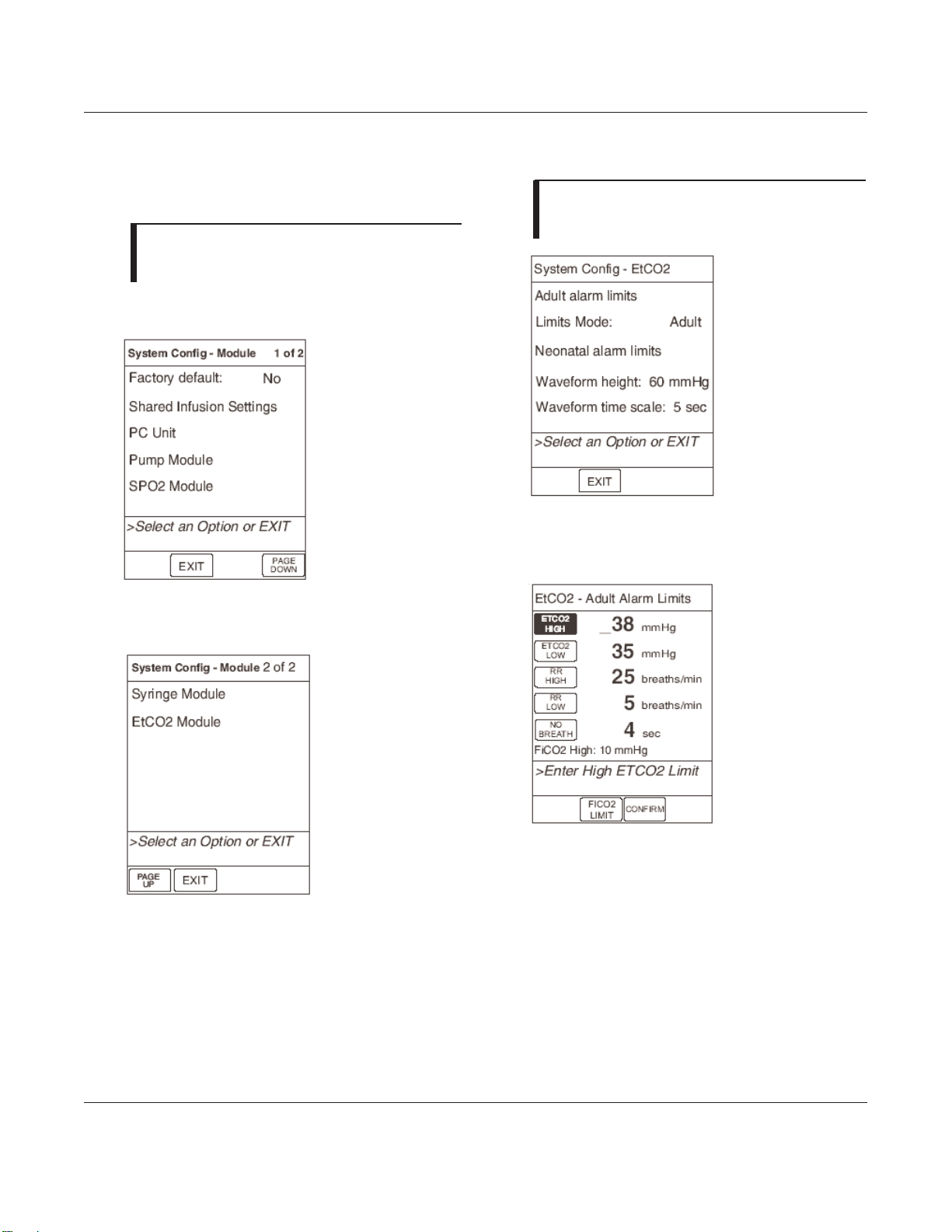
To access System Configuration options:
NOTE: Refer to EtCO2Module DFU for
alarm settings. If profiles are enabled, those
settings are set by the profile.
1. Hold OPTIONS key at power up.
2. Press
PAGE DOWN soft key.
3. Press EtCO
2
Module soft key.
2.4.1 Alarm Limits
NOTE: The following examples show adult
alarm limits for illustration. Follow the same
steps for neonatal alarm limits.
1. From the System Config - EtCO
2
display, press the Adult alarm limits or
Neonatal alarm limits soft key.
2. To change an alarm limit, press the soft
key next to that parameter. The selected
parameter is highlighted.
CHECKOUT AND CONFIGURATION
2-3
Alaris®EtCO2Module (8300 Series)
Technical Service Manual
2.4 CONFIGURATION SETUP
Page 16
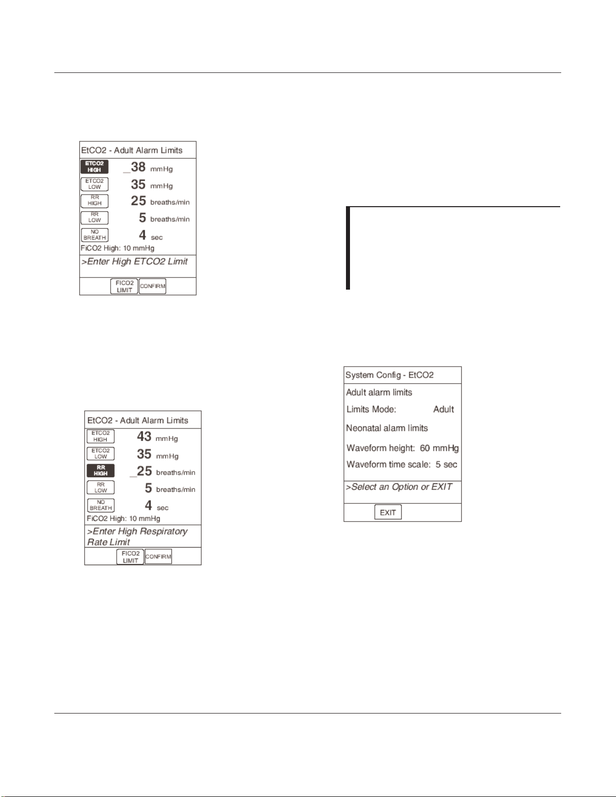
3. Enter a numeric value for the selected
alarm limit. Use the numeric keypad or
the up or down arrow keys to enter the
value. If a valid value appears in the
field for three seconds, the display
shows the prompt > Press CONFIRM to
Apply Changes.
4. Press ENTER on the Point-of-Care Unit
to confirm the value. Once you press
ENTER, the next limit is highlighted and
the display prompts for an entry.
5. To change another alarm limit, press the
soft key for that parameter and enter a
new value.
6. Once all changes are complete, press
the CONFIRM soft key.
2.4.2 Limit Mode
NOTES:
• The following examples show adult alarm
limits for illustration. Follow the same
steps for neonatal alarm limits.
• If a profile is in use for programming, you
cannot change the Limit Mode.
1. To change the Limit Mode, toggle its
value from the System Config - EtCO
2
display, or use the Limits mode soft
key.
2. To toggle the value: From the System
Config - EtCO
2
display, press the soft
key for the Limit Mode selection. Every
key press toggles the value between
Adult and Neonatal.
3. To use the soft key: From the System
Config - EtCO
2
display, press the
Limits Mode soft key.
CHECKOUT AND CONFIGURATION
2-4
Alaris®EtCO2Module (8300 Series)
Technical Service Manual
2.4 CONFIGURATION SETUP (Continued)
2.4.1 Alarm Limits (Continued)
Press the Limits
Mode soft key to
toggle between the
two acceptable
values
Page 17
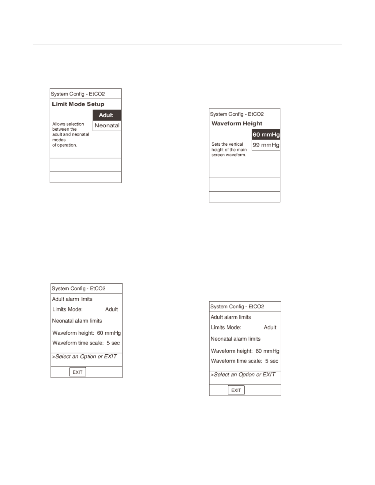
4. Press the soft key to select the Limit
Mode Setup display, or press CANCEL
to exit the System Config - EtCO
2
display without changing the value.
2.4.3 Waveform Height
1. To change the waveform height, you can
toggle its value from the System Config
- EtCO
2
display, or you can use the
Waveform height soft key.
2. To toggle the value: From the System
Config - EtCO
2
display, press the soft
key for the waveform height value.
Every key press toggles the value
between 60 and 99 mmHg.
3. To use the soft key: From the System
Config - EtCO
2
display, press the
Waveform height soft key.
4. Press the soft key to select the
waveform height, or press CANCEL to
exit the Waveform Height display
without changing the value.
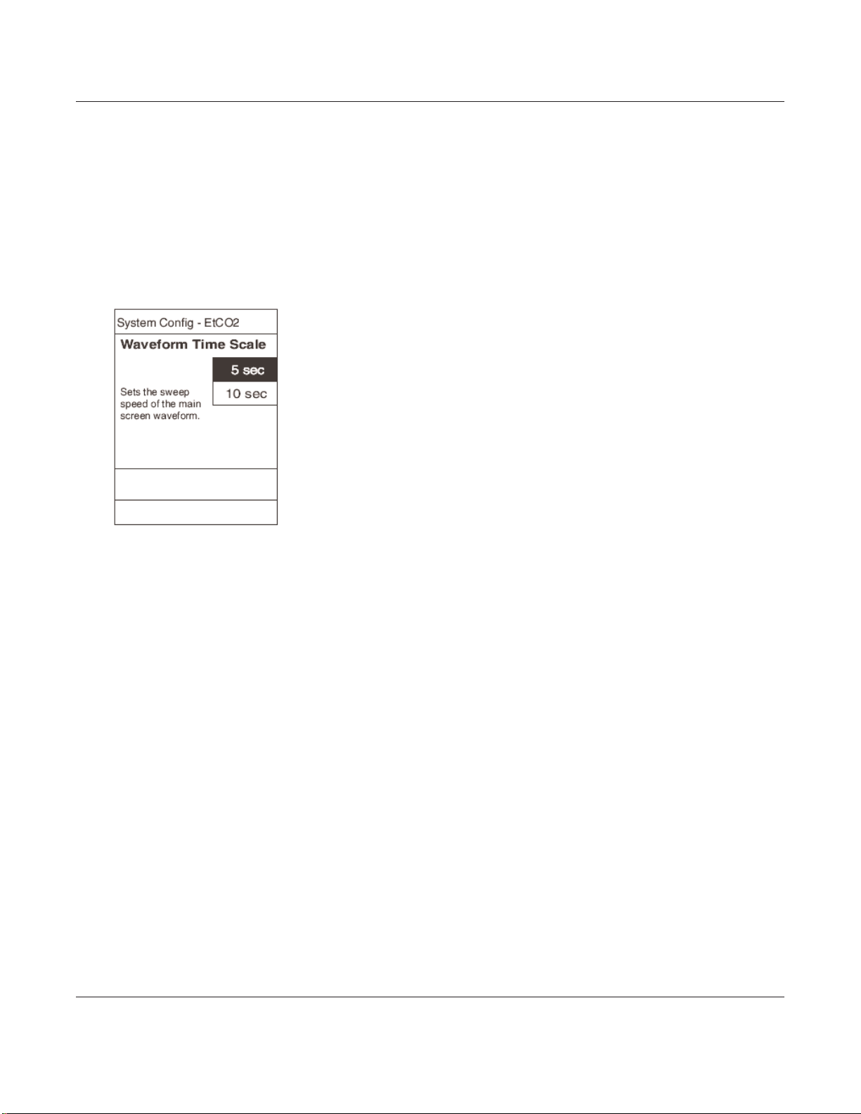
2.4.4 Waveform Time Scale
1. To change the waveform time scale, you
can toggle its value from the System
Config - EtCO
2
display, or you can use
the Waveform time scale soft key.
CHECKOUT AND CONFIGURATION
2-5
Alaris®EtCO2Module (8300 Series)
Technical Service Manual
2.4 CONFIGURATION SETUP (Continued)
2.4.2 Limit Mode (Continued)
Press the
Waveform height
soft key to toggle
between the two
acceptable values
Press the
Waveform time
scale soft key to
toggle between the
two acceptable
values
Page 18
CHECKOUT AND CONFIGURATION
2-6
Alaris®EtCO2Module (8300 Series)
Technical Service Manual
2. To toggle the value: From the System
Config - EtCO2display, press the soft
key for the Waveform Time Scale
value. Every key press toggles the value
between 5 and 10 sec.
3. To use the soft key: From the System
Config - EtCO
2
display, press the
Waveform time scale soft key.
4. Press the soft key to select the
waveform height, or press CANCEL to
exit the Waveform time scale display
without changing the value.
2.4 CONFIGURATION SETUP (Continued)
2.4.4 Waveform Time Scale (Continued)
Page 19

CHECKOUT AND CONFIGURATION
2-7
Alaris®EtCO2Module (8300 Series)
Technical Service Manual
EtCO2Alarm Limit, High
EtCO
2
Alarm Limit, Low
FiCO
2
Alarm Limit, High
Limit Mode
No Breath Alarm
Respiratory Rate Alarm
Limit, High
Respiratory Rate Alarm
Limit, Low
Waveform Height
Waveform Time Scale
Table 2-1. Record of Configured Instruments
#1 #2 #3 #4
Instrument ID/Serial #
NOTE: If profiles are enabled, alarm limits are set by the profile.
Page 20

CHECKOUT AND CONFIGURATION
2-8
Alaris®EtCO2Module (8300 Series)
Technical Service Manual
THIS PAGE
INTENTIONALLY
LEFT BLANK
Page 21

3 PREVENTIVE MAINTENANCE
Page 22

Page 23

Chapter 3 — PREVENTIVE MAINTENANCE
3-1Alaris
®
EtCO2Module (8300 Series)
Technical Service Manual
Failure to perform regular and preventive
maintenance inspections may result in improper
instrument operation.
WARNING
3.1 INTRODUCTION
Perform regular and preventive
maintenance inspections to ensure that the
EtCO
2
Module remains in good operating
condition:
• Perform regular inspections before each
use.
• Perform preventive maintenance
inspections annually.
These requirements and guidelines are
intended to complement the intent of Joint
Commission on Accreditation of Healthcare
Organizations (
JCAHO) requirements.
3.2 REGULAR AND PREVENTIVE
MAINTENANCE INSPECTIONS,
CALIBRA TION
Use the Maintenance Software (version 7 or
later) to perform calibration and preventive
maintenance.
Contact Cardinal Health Technical Support if
you need help obtaining or using the
Maintenance Software.
3.3 CLEANING
Refer to the PC Unit section of the Alaris
®
System DFU.
Page 24

PREVENTIVE MAINTENANCE
3-2
Alaris®EtCO2Module (8300 Series)
Technical Service Manual
THIS PAGE
INTENTIONALLY
LEFT BLANK
Page 25

4 PRINCIPLES OF OPERATION
Page 26

Page 27

Chapter 4 — PRINCIPLES OF OPERATION
4-1Alaris
®
EtCO2Module (8300 Series)
Technical Service Manual
4.1 INTRODUCTION
This chapter describes the principles of
operation for the EtCO
2
Module and its
major subsystems.
Refer to the PC Unit/Pump Module
Technical Service Manual for Point-of-Care
Unit information.
4.2 GENERAL INFORMATION
The EtCO
2
Module uses Oridion’s patented
Microstream
®
non-dispersive infrared (NDIR)
spectroscopy to continuously measure the
amount of CO
2
during every breath, the
amount of CO
2
present at the end of
exhalation (EtCO
2
) and during inhalation
(FiCO
2
), and the Respiratory Rate. The
EtCO
2
Module is a side stream capnograph.
The Microstream
®
Disposables deliver a
sample of the inhaled and exhaled gases
from the ventilator disposable or directly
from the patient (via an oral/nasal cannula)
into the monitor for CO
2
measurement.
Moisture and patient secretions are
extracted from the sample by the
Microstream
®
inline filter while maintaining
the shape of the CO
2
waveform.
The 50 mL/min sampling flow rate reduces
liquid and secretion accumulation,
decreasing the risk of obstruction in the
sample pathway in humid ICU
environments. The small sample size
required by Microstream
®
eliminates the
need for water traps and prevents excess
fluid accumulation.
The EtCO
2
Module draws a gas sample
through a microsample cell (15 microliters).
This extremely small volume is quickly
flushed, allowing for a rise time of
Page 28

PRINCIPLES OF OPERATION
4-2
Alaris®EtCO2Module (8300 Series)
Technical Service Manual
approximately 190 ms and accurate CO
2
readings, even at high respiration rates.
The Microbeam IR source illuminates the
microsample cell and the reference channel.
This proprietary IR light source generates
only the specific wavelengths characteristic
of the CO
2
absorption spectrum. The IR light
that passes through the microsample cell
and the IR light that passes through the
reference channel are measured by IR
detectors.
The microcomputer in the EtCO
2
Module
calculates the CO
2
concentration by
comparing the signals from both channels.
No operator intervention is required for
routine moisture or condensate.
All Microstream
®
Disposables contain an
inline hydrophobic filter to extract
condensate and/or patient secretions while
maintaining measurement and waveform
integrity. For humid conditions within the
operating parameters of the EtCO
2
Module
and Microstream
®
Disposables, humidity
has no quantitative effect on the CO
2
concentration, given the small 50 mL/min
sample size rate. In high humidity
environments or extended monitoring
periods (24-72 hours) only Microstream
®
Disposables designed for those instances
should be used. In the event of humidity or
condensate outside the EtCO
2
Module’s
operating specifications, the EtCO
2
Module
will present a “Remove Blocked Disposable”
message.
Due to the relatively small sampling size
needed for EtCO
2
readings, partial pressure
does not affect the ability of the EtCO
2
Module to measure EtCO2, as long as the
50 mL/min rate can be achieved.
Microstream
®
Disposables are single-use,
disposable devices which must be changed
with each use. The manufacturer’s sample
flow, 50 mL/minute, does not affect the
disposable’s life; however, humidity and
specific patient conditions may shorten the
effective life of the disposables.
Microstream
®
Disposables are rated for up
to 24 hour and 72 hour use, depending on
the specific Microstream
®
Disposable.
The EtCO
2
Module provides readings in
compliance with BTPS (body temperature,
pressure, saturation) standards. There is no
effect on accuracy due to cyclic pressure up
to 10 kPa.
NOTE: BTPS (body temperature, pressure,
saturation assumed 37°C, 47 mmHg)
calculations are made according to:
PCO2= FCO2X (Pb - 47)
Where:
FCO2is the fractional concentration of CO
2
in dry gas, and FCO2= % CO2/100.
Pb is the ambient pressure.
PCO2is the partial pressure of CO2at
BTPS.
4.2 GENERAL INFORMATION (Continued)
Page 29

5 CORRECTIVE MAINTENANCE
Page 30

Page 31

NOTE: Due to product changes over time,
components/ assemblies illustrated in this chapter
may differ from the instrument you disassemble. If
there are any questions, look for Service Bulletins
related to this chapter or contact Cardinal Health
Technical Support.
5.1 INTRODUCTION
This chapter describes how to disassemble
and reassemble the EtCO
2
Module.
For more efficient repair, read the “Principles
of Operation” chapter for information on the
mechanical and electrical functions of the
EtCO
2
Module.
The surface mount devices on the circuit
boards are not field repairable. Return
circuit boards to an authorized Cardinal
Health Service Center for repair. Attempting
circuit board repairs voids all warranties.
Whenever the EtCO2Module is repaired,
perform the minimum tests required for new
instrument checkout (use Maintenance
Software v
7 or later).
For information on replacement parts, see
the “Illustrated Parts Breakdown” chapter.
Following any level of maintenance, perform
the applicable tests (refer to “Level of
Testing Guidelines” table).
5-1
Alaris®EtCO2Module (8300 Series)
Technical Service Manual
Chapter 5 — CORRECTIVE MAINTENANCE
Disconnect the EtCO2Module from the Alaris
®
System before performing maintenance. qualified
personnel using proper grounding techniques
should open the instrument case.
WARNING
CMOS devices are sensitive to static electrical
charges and may be damaged during repair if the
repair activity is not performed in an electrostatic
discharge (
ESD) protected environment using
approved ESD protective procedures, including
personnel grounding.
CAUTION
Page 32

Follow these procedures in order for the
most efficient disassembly of EtCO
2
Module
subassemblies. To reassemble the EtCO
2
Module, reverse the disassembly steps.
NOTE: Perform all maintenance on an
antistatic surface, preferably a grounded
antistatic mat.
Before adhering gaskets and labels to the
instrument, clean the surface with a cotton
swab or soft cloth lightly dampened with
70% Isopropyl Alcohol.
5-2
Alaris®EtCO2Module (8300 Series)
Technical Service Manual
CORRECTIVE MAINTENANCE
5.2 DISASSEMBLY/REASSEMBLY
Disconnect the EtCO2Module from the
Alaris
®
System Before attempting
disassembly.
CAUTION
To avoid the risk of electrical hazard or
damage to the instrument circuitry, do not
spray fluids directly onto the instrument or
allow fluids to enter the instrument.
CAUTION
Table 5-1. Required Materials, Supplies and Tools
NOTE: Contact/source information is subject to change.
• Loctite 242 (http://www.loctite.com)
• Silicone grease, Dow Corning Molykote
33, or equivalent (http://www.dowcorning.com)
•
#1 Phillips screwdriver
•
#2
Phillips screwdriver
• Small diagonal cutters
• Lint-free cloth (such as, Kimwipes or lint-free tissue)
Page 33

5.2.1 Latch Assembly and Feet
1. Remove two (
2) screws attaching Latch
Assembly to bottom of Rear Case and
remove Latch Assembly components.
2. Pull two (2) Feet from underside of
module.
NOTE: Pay close attention to Compression
Spring location and orientation to ensure
proper installation during reassembly.
During Reassembly:
When reinstalling the Latch Assembly, press
toward outer edge of the module and screw
into position.
Apply a thin layer of Dow Corning
Molykote
33 (or equivalent) silicone grease
to Feet.
NOTE: The Feet press-fit into the module.
5-3
Alaris®EtCO2Module (8300 Series)
Technical Service Manual
CORRECTIVE MAINTENANCE
Feet
Rear Case
Latch Assembly
components
5.2 DISASSEMBLY/REASSEMBLY (Continued)
Compression Spring
Page 34

5-4
Alaris®EtCO2Module (8300 Series)
Technical Service Manual
CORRECTIVE MAINTENANCE
5.2 DISASSEMBLY/REASSEMBLY (Continued)
5.2.2 IUI Connectors
Remove two (
2) screws attaching each IUI
(left and right) to module.
During Reassembly:
• Ensure ground clips are still installed on
both IUI connectors.
• To install IUI Connector Gasket, remove
protective backing and adhere to IUI
Connector.
IUI Connector, Left
IUI Connector, Right
IUI Connector Seal, Right
IUI Connector Gasket, Right
Ground clip located at each mounting
hole on both IUI Connectors
Page 35

5.2.3 Rear Case
1. Remove two (
2) screws (and associated
washers) attaching Rear Case to
chassis assembly.
2. Pull Rear Case away from chassis
assembly.
During Reassembly:
Ensure that Silicone Tubing gasket in Rear
Case is in place and undamaged.
5.2 DISASSEMBLY/REASSEMBLY (Continued)
Rear Case Assembly
Silicone Tubing
gasket
5-5
Alaris®EtCO2Module (8300 Series)
Technical Service Manual
CORRECTIVE MAINTENANCE
Screws and
Washers (x2)
Page 36

5.2.4 Frame Assembly
1. Remove six (6) screws attaching Frame
Assembly to Front Case.
2. Use small diagonal cutters to remove
upper snap rivet attaching Power Board
to Frame Assembly.
2. Remove the IUI Bracket Strap from the
Display Board.
3. Carefully remove Frame Assembly from
Front Case Assembly, then place the
Frame Assembly to the left of the Front
Case, taking care not to damage hoses
and wires.
4. Disconnect electrical harness from
Oridion Module.
5. Disconnect the inlet and exhaust hoses
on the Oridion Module.
During Reassembly:
• Fit the top flange of the Frame Assembly
into the square slot on the Status
Indicator Lens.
• Fit the connectors on the Power Board
and Logic Board into the two (2)
connectors on the Display Board.
• Ensure that the harness and hoses are
fully connected, and route them so they
are not pinched during reinstallation.
• Slide the IUI Bracket Strap under the
keypad ground wire on the Display
Board.
5-6
Alaris®EtCO2Module (8300 Series)
Technical Service Manual
CORRECTIVE MAINTENANCE
5.2 DISASSEMBLY/REASSEMBLY (Continued)
Frame
Assembly
Exhaust hose
IUI
Bracket
Strap
Snap
Rivet
Front Case
Assembly
Electrical
Harness
When using cutters to remove snap
rivet, take care not to cut the rivet.
CAUTION
Inlet hose
Screw
Keypad
ground wire
IUI
Bracket
Strap
Keypad
ground
wire
Page 37

5-7
5.2 DISASSEMBLY/REASSEMBLY (Continued)
5.2.5 Logic Board
1. Use small diagonal cutters to remove
snap rivet attaching Logic Board to
Frame Assembly .
2. Remove Logic Board from Frame
Assembly.
During Reassembly:
• Seat the holes in the Logic Board over
the standoffs on the IUI Bracket.
• Reinstall the snap rivet and its locking pin
to secure the Logic Board to the Frame
Assembly.
Snap
Rivet
Logic
Board
Standoff on
IUI Bracket
When using cutters to remove snap
rivet, take care not to cut the rivet.
CAUTION
Frame
Assembly
Alaris®EtCO2Module (8300 Series)
Technical Service Manual
CORRECTIVE MAINTENANCE
Page 38

5-8
Alaris®EtCO2Module (8300 Series)
Technical Service Manual
CORRECTIVE MAINTENANCE
5.2.6 Power Board/Oridion Module
1. Use small diagonal cutters to remove
upper (if installed) and lower snap
rivet(s) attaching Power Board to Frame
Assembly. If installed, remove IUI
Bracket Strap.
2. Remove screw holding PCB retainer to
Frame Assembly .
3. Remove Power Board from Frame
Assembly.
4. Disconnect electrical harness between
Power Board and Oridion Module.
5. Separate Power Board and Oridion
Module:
• Remove three (3) screws from
underside of Power Board.
• Remove screw and nut attaching
PCB retainer to Power Board.
During Reassembly:
• Ensure that Oridion Module and PCB
retainer are positioned correctly over the
Power Board before reinstalling.
• Reinstall the IUI Bracket Strap and snap
rivets to secure the Power Board to the
Frame Assembly .
5.2 DISASSEMBLY/REASSEMBLY (Continued)
PCB retainer
Power
Board
Oridion
Module
When using cutters to remove snap
rivet, take care not to cut the rivet.
CAUTION
Page 39

5-9
Alaris®EtCO2Module (8300 Series)
Technical Service Manual
CORRECTIVE MAINTENANCE
5.2.7 IUI Bracket
Flex IUI Bracket away from key pins and
remove bracket and Ground Strap from
Frame Assembly .
During Reassembly:
Position IUI Bracket over key pins on Frame
Assembly
5.2 DISASSEMBLY/REASSEMBLY (Continued)
Key pin
Frame
Assembly
IUI Bracket
Ground
Strap
Page 40

5-10
Alaris®EtCO2Module (8300 Series)
Technical Service Manual
CORRECTIVE MAINTENANCE
5.2 DISASSEMBLY/REASSEMBLY (Continued)
5.2.8 Gas Inlet/Outlet Door
NOTE: To hold Torsion Spring in place
during removal, hold Spring Retainer firmly
when removing Cotter Pin.
1. From inside Front Case Assembly,
straighten Cotter Pin legs and from
Spring Retainer.
2. Slowly lift Spring Retainer to relieve
compression on Torsion Spring.
3. Remove Torsion Spring.
4. Remove Door from Front Case
Assembly.
During Reassembly:
1. Place Torsion Spring on Door shaft with
long end facing up.
2. Align Spring Retainer with shaft, push
Torsion Spring down, insert Cotter Pin
through Spring Retainer, then wind
Cotter Pin legs around Door shaft to
secure.
3. Wind Torsion Spring 1/4-turn and secure
long end of Spring under Spring
Retainer.
Door
Status
Indicator
Lens
Front
Case
Display
Board
Spring
Retainer
Cotter
Pin
Spring
Retainer
Cotter
Pin
Torsion
Spring
Torsion
Spring
Page 41

5-11
Alaris®EtCO2Module (8300 Series)
Technical Service Manual
CORRECTIVE MAINTENANCE
5.2.9 Luer Assembly
1. Remove three (
3) screws attaching Luer
Retainer to Front Case.
2. Remove Luer Retainer from Front Case.
3. Separate Luer Assembly from Luer
Retainer.
During Reassembly:
• Ensure that O-ring is correctly positioned
on Luer Assembly, then apply a small
bead of water around the O-ring: this
helps O-ring to remain in place when
installing Luer Assembly into Front Case.
• Position Luer Retainer over screw holes
in Front Case, then install screws to
secure.
5.2 DISASSEMBLY/REASSEMBLY (Continued)
Front Case
O-ring
Luer
Assembly
Luer
Retainer
Page 42

5-12
Alaris®EtCO2Module (8300 Series)
Technical Service Manual
CORRECTIVE MAINTENANCE
5.2.10 Display Board
1. Remove screw attaching ground wire to
Display Board.
2. Cut cable tie, then disconnect Keypad
Harness and Backlight harnesses from
Display Board.
3. Remove three (3) screws attaching
Display Board to Front Case.
4. Remove Display Board from Front Case
During Reassembly:
• When reinstalling Display Board, slide
LEDs under Status Indicator Lens.
• Reinstall screws attaching Display Board
to Front Case.
• Reinstall Keypad and Backlight Harness,
then replace the cable tie.
• Reinstall the keypad ground wire.
5.2 DISASSEMBLY/REASSEMBLY (Continued)
Display
Board
Front Case
Status
Indicator
Lens
Keypad
Ground
Wire
Keypad
Harness
Page 43

5-13
Alaris®EtCO2Module (8300 Series)
Technical Service Manual
CORRECTIVE MAINTENANCE
5.2.11 Status Indicator Lens
1. Remove two (2) screws attaching Status
Indicator Lens and Gasket to Front
Case.
2. Remove Status Indicator Lens.
5.2 DISASSEMBLY/REASSEMBLY (Continued)
Status
Indicator
Lens
Front
Case
Gasket
Screws (x2)
Page 44

Table 5-2. Torque Values
Functional Application Item Description Torque Value
FINAL ASSEMBLY
IUI Connectors 6-32 x
7
/16 12 in/lb
Latch Assembly 4-40 x
3
/8
Torx Security 6 in/lb
Rear Case - Internal Frame 6-32 x
7
/
16 12 in/lb
FRONT CASE ASSEMBLY
Display Board 4-40 x
5
/16
6 in/lb
Internal Frame - Front Case 4-40 x
3
/
4 6 in/lb
IUI Bracket Strap and Ground Wire 4-40 x
5
/16 6 in/lb
Status Indicator Lens 4-20 x
5
/16 6 in/lb
Luer Mount 4-20 x
5
/
16 6 in/lb
Power Board/Oridion Module 4-40 x
1
/8 6 in/lb
5-14
Alaris®EtCO2Module (8300 Series)
Technical Service Manual
CORRECTIVE MAINTENANCE
Page 45

5-15
Alaris®EtCO2Module (8300 Series)
Technical Service Manual
CORRECTIVE MAINTENANCE
Table 5-3. Level of Testing Guidelines
Display Board NNNN N N N
Frame Assembly NNNNNN N N
Front Case NNNNNN N N
Gas Inlet/Outlet Door NNNNNN N N
IUI Bracket NNX NNN N N
IUI Connectors NN N
Latch Assembly and Feet N
Logic Board NNNNNN N
Luer Assembly NNNNNN N N
Power Board/Oridion Module NNN NN
Rear Case NN
Status Indicator Lens NNNNNN N N
Miscellaneous: Ð
Instrument dropped NNX NNN N N
Instrument software flashed N
New instrument checkout NNX NNN N N
No fault found
N
(instrument not opened)
No fault found
NNNNNN N N
(instrument opened)
Channel ID/IUI Connector Test
CO
2
Sensor Calibration
Keypad Test
CO
2
Sensor Verification
Alarm Test
Tests to Perform
N
= Required
X = If verification fails.
Blank = Not Applicable
Repair/Replacement of: Ð
Simultaneous Display Test
Visual/Instrument Inspection
NOTES:
• Use the Maintenance Software to perform testing and calibration.
• After performing any calibration procedure, always perform the
associated verification test.
Leak Down Test
Page 46

THIS PAGE
INTENTIONALLY
LEFT BLANK
5-16
Alaris®EtCO2Module (8300 Series)
Technical Service Manual
CORRECTIVE MAINTENANCE
Page 47

6 TROUBLESHOOTING
Page 48

Page 49

Chapter 6 — TROUBLESHOOTING
6-1Alaris
®
EtCO2Module (8300 Series)
Technical Service Manual
6.1 INTRODUCTION
This chapter describes possible technical
problems and operating errors that may
occur while using the EtCO
2
Module. Refer
to this chapter before attempting to service
the EtCO
2
Module.
Refer to the PC Unit / Pump Module
Technical Service Manual for information on
viewing the Malfunction Log.
Use extreme caution in servicing the
instrument when connected to AC power.
Hazardous voltages are present when AC
power is connected, regardless of the setting
of the power switch.
WARNING
Page 50

TROUBLESHOOTING
6-2
Alaris®EtCO2Module (8300 Series)
Technical Service Manual
Table 6-1. Technical Troubleshooting Guide
Follow the steps in the order they are listed until the problem/fault is corrected. Before making a final
diagnosis, visually inspect the instrument for damage and pay particular attention to the power cord
and plug. Following repair/replacement, use Maintenance Software to perform the required tests (see
Chapter
5). Perform the Ground Current Leakage and Ground Leakage tests described in the PC Unit /
Pump Module Technical Service Manual to verify that the system is electrically safe.
Problem Remedy
Display Problem 1. Check cable connections.
2. Replace Display.
3. Replace Logic Board.
4. Return to factory.
Key Stuck Alarm 1. Turn instrument off and back on to see if problem clears.
2. Replace Keypad Assembly.
3. Replace Logic Board.
4. Return to factory.
Instrument Malfunction 1. Turn instrument off and back on to see if problem clears.
2. Refer to alarm history, malfunction codes (Table 6-2), and subsystem codes (see
PC Unit / Pump Module (8000/8100 Series) Technical Service Manual).
Intermittent Operation 1. Check connections to Logic Board.
2. Replace Logic Board.
3. Return to factory.
Page 51

TROUBLESHOOTING
6-3
Table 6-2. Malfunction Codes
Refer to the PC Unit / Pump Module Technical Service Manual for information on viewing the
Malfunction Log.
Alaris®EtCO2Module (8300 Series)
Technical Service Manual
Malfunction
Code
Subsystem Explanation Remedy
500 Main Logic Board See NOTE See NOTE
510 Keypad Decoder See NOTE See NOTE
511 Keypad Decoder Comm Error See NOTE See NOTE
530 Keypad Error See NOTE See NOTE
550 IUI Error See NOTE See NOTE
560 Power Supply Board Error See NOTE See NOTE
570 EtCO2Board Error See NOTE See NOTE
571 EtCO2Board Comm Error See NOTE See NOTE
6200 EtCO2Board Error Failed continuous built-in
tests.
Cycle power. If error repeats,
replace EtCO
2
Board.
6210 EtCO2Board Error Communications error. Cycle power. If error repeats,
replace EtCO2Board.
6220 EtCO2Board Error Configuration error. Cycle power. If error repeats,
replace EtCO
2
Board.
6230 EtCO2Board Error Received value out of
range.
Replace Microstream
Disposable device. If error
repeats, replace EtCO
2
Board.
6240 EtCO2Board Error Missing sensor status. Replace Microstream
Disposable device. If error
repeats, replace EtCO
2
Board.
NOTE: Refer to Troubleshooting information in the PC Unit / Pump Module Technical Service Manual for more
detailed descriptions of codes.
Page 52

TROUBLESHOOTING
6-4
Alaris®EtCO2Module (8300 Series)
Technical Service Manual
THIS PAGE
INTENTIONALLY
LEFT BLANK
Page 53

7 ILLUSTRATED PARTS
BREAKDOWN
Page 54

Page 55

Chapter 7 — ILLUSTRATED PARTS BREAKDOWN
7-1Alaris
®
EtCO2Module (8300 Series)
Technical Service Manual
7.1 INTRODUCTION
The illustrated parts breakdown for the
EtCO
2
Module is divided according to its
major assemblies.
7.2 ILLUSTRATIONS
Use the exploded views to identify the parts
of each assembly. Item numbers (the
numbers in bubbles) in the illustration
correspond to the item number in the parts
list. Apart that does not have an item
number is part of a higher assembly.
NOTE: Due to product changes over time,
illustrations in this chapter can differ from the
instrument under service. See applicable
Service Bulletins or contact Cardinal Health
Technical Support for more information.
7.3 PARTS LIST
The parts lists include the following
information for replaceable parts :
• Item: This number corresponds to the
item number in the illustration.
• Part Number: Use this number to order
the part. If a part number is not provided,
that part is not available for sale, is part
of a kit or higher assembly, or can only
be replaced/repaired by Cardinal Health
authorized service personnel.
• Description: Description of the part.
• QTY: Total number of each item used.
Page 56

Item Part Number Description QTY
15 146980-000 Gasket, Status Indicator 1
16 148140-000 Retainer, Luer 3
17 321245 O-Ring, 0.364 ID x 0.070 W 60 Duro 1
20 10013666
Front Case/Keypad Assembly
(Assembled parts: Front Case, Keypad, items
15, 25, 841 qty. 2)
1
21 148128-102 Door Assembly 1
22 148130-002 Spring, Torsion 1
23 148228-000 Retainer, Spring 1
24 3211246 Pin, Cotter, 1/32 OD x 3/8 L, extended prong 1
25 146978-001 Lens, Status Indicator 1
32 144424-100 LED, Keyboard Backlight 1
35 148112-103 Board Assembly, Display 1
36 321270 Standoff, F/F, 3/16
hex x
3
/8
4-40, AL
3
37 10011768 Module, Oridion 1
39 TC10003682 Board Assembly, Power Supply 1
40 142833-000 Bracket, IUI 1
45 148131-001 Frame 1
46 148227-002 Retainer, PCB 1
7.4 ORDERING PARTS
Parts can be ordered by writing or calling
Cardinal Health Customer Service (refer to
"General Contract Information" page at
beginning of this manual). When requesting
a part, provide the following information:
• Instrument name and model number; for
example, EtCO
2
Module, Model 8300.
• Instrument software version. Refer to
Alaris
®
System DFU
for directions on how
to view software version.
• Part number.
• Part description, as provided in parts list.
• For labels, specify required language.
ILLUSTRATED PARTS BREAKDOWN
7-2
Alaris®EtCO2Module (8300 Series)
Technical Service Manual
Table 7-1. Parts List
NOTE: An “assembly” is a preassembled group of parts. A “kit” is a group of unassembled parts.
Page 57

7-3
ILLUSTRATED PARTS BREAKDOWN
Alaris®EtCO2Module (8300 Series)
Technical Service Manual
Item Part Number Description QTY
47 148249-100
Assembly, EtCO2Cable
1
55 TC10003899 Board Assembly, Logic 1
60 146992-001 Strap, Ground, IUI Bracket 1
70
Silicone Grease, Molykote Medium or equivalent As required
75 142794-000 Foot, Rubber 2
80 320763 Tubing, Medium Silicone, 0.030 x 0.065 x 0.18 1
85 10013667 Assembly, Rear Case
(Assembled parts: Rear Case, Nameplate Label, items 75, 80, 603,
620
)
1
90 146456-000 Kit, Latch
(Includes: Latch, Compression Spring, Leaf Spring, Support)
1
120 147077-100 Kit, Right IUI Connector
(Includes: Right Seal, Right IUI Connector)
1
130 147078-100 Kit, Left IUI Connector
(Includes: Left Gasket, Left IUI Connector)
1
135 10013668 Kit, Luer
(Includes: Luer Assembly, item 17)
1
603 125569 Label, Serial Number, Replacement 1
620 148405-000 Label, Patent 1
630 148372-000 Label, Microstream 1
635 10010621 Label, Door 1
645 145820-000 Seal, Instrument 1
820 834031 Cable Tie, 4-in. L 1
825 300348 Screw, Machine, 4-40 x 3/4 PHH PHH 6
830 806112 Rivet, Snap, 0.125 dia., Nylon BLK 3
835 320855 Screw, 6-32 x 7/16 PHH PNH SS 6
840 320908 Washer, Flat, 0.146 ID x 0.270 OD x 0.03 THK, SS 10
841 300923 Screw, Machine, 4-40 x 5/
16 PHL PNH ZNC PLT STL
7
Table 7-1. Parts List (Continued)
Page 58

Table 7-1. Parts List (Continued)
ILLUSTRATED PARTS BREAKDOWN
7-4
Alaris®EtCO2Module (8300 Series)
Technical Service Manual
Item Part Number Description QTY
842 303822 Screw, 3LOB, 4-20 x 7/16
PNH PHH ZNC-STL
3
843 300347 Screw, Machine, 4-40 x 5/8
PNH PHH
1
844 300928 Nut, Hex, 4-40 STL PL 1
845 300345 Screw, Machine, 4-40 x 1/4 PHL PNH ZNC PLT STL 4
846 305121 Screw, Machine, PNH 6
10011281
Directions for Use, EtCO
2
1
Not sold by Cardinal Health.
Page 59

7-5
ILLUSTRATED PARTS BREAKDOWN
Figure 7-1. Housing Assembly
130
85
835
635
630
835
120
840
20
Alaris®EtCO2Module (8300 Series)
Technical Service Manual
4 PL
2 PL
2 PL
Page 60

ILLUSTRATED PARTS BREAKDOWN
7-6
Alaris®EtCO2Module (8300 Series)
Technical Service Manual
Figure 7-2. Frame/Front Case Assembly
841
825
830
3 PL
6 PL
39
32
55
Page 61

7-7
ILLUSTRATED PARTS BREAKDOWN
Alaris®EtCO2Module (8300 Series)
Technical Service Manual
Figure 7-3. IUI Bracket/Frame Assembly
45
60
40
Page 62

3 PL
ILLUSTRATED PARTS BREAKDOWN
7-8
Alaris®EtCO2Module (8300 Series)
Technical Service Manual
Figure 7-4. Oridion Module/Power Supply Board
46
39
36
37
8 PL
843
844
840
6 PL
846
Page 63

7-9
ILLUSTRATED PARTS BREAKDOWN
Alaris®EtCO2Module (8300 Series)
Technical Service Manual
Figure 7-5. Front Case Assembly
15
25
21
35
16
17
23
24
135
842
3 PL
22
23
24
22
841
3 PL
841
2 PL
Page 64

ILLUSTRATED PARTS BREAKDOWN
7-10
Alaris®EtCO2Module (8300 Series)
Technical Service Manual
Figure 7-6. Rear Case Assembly/Latch Kit
85
620
603
Nameplate label
75
90
2 PL
80
1
Labels (items
603 and 620) are provided as separate items and as part of Rear
Case Assembly Kit. Reference Table 7-1, item 85 for a list of parts included in
Rear Case Assembly Kit.
3
Before adhering Serial Number Label (item
603):
1. Print instrument model and serial number on label in permanent black ink.
2. Apply clear overlay to completely cover label.
2
Nameplate Label is available only as part of Rear Case Assembly Kit. This
label has a regulatory mark, and any level of service that requires its
replacement must be performed at the factory.
1
1
2
1
3
Page 65

7-11
ILLUSTRATED PARTS BREAKDOWN
Alaris®EtCO2Module (8300 Series)
Technical Service Manual
Figure 7-7. EtCO2Cable Assembly
47
Page 66

THIS PAGE
INTENTIONALLY
LEFT BLANK
ILLUSTRATED PARTS BREAKDOWN
7-12
Alaris®EtCO2Module (8300 Series)
Technical Service Manual
Page 67

Page 68

Alaris®and Guardrails®are registered trademarks of Cardinal Health, Inc. or one of its subsidiaries. Microstream®is a registered trademark of
Oridion Medical 1987 Ltd. All other trademarks belong to their respective owners.
Part Number 10011051 ©2005, 2006 Cardinal Health, Inc. or one of its subsidiaries. All rights reserved.
 Loading...