

Page 1
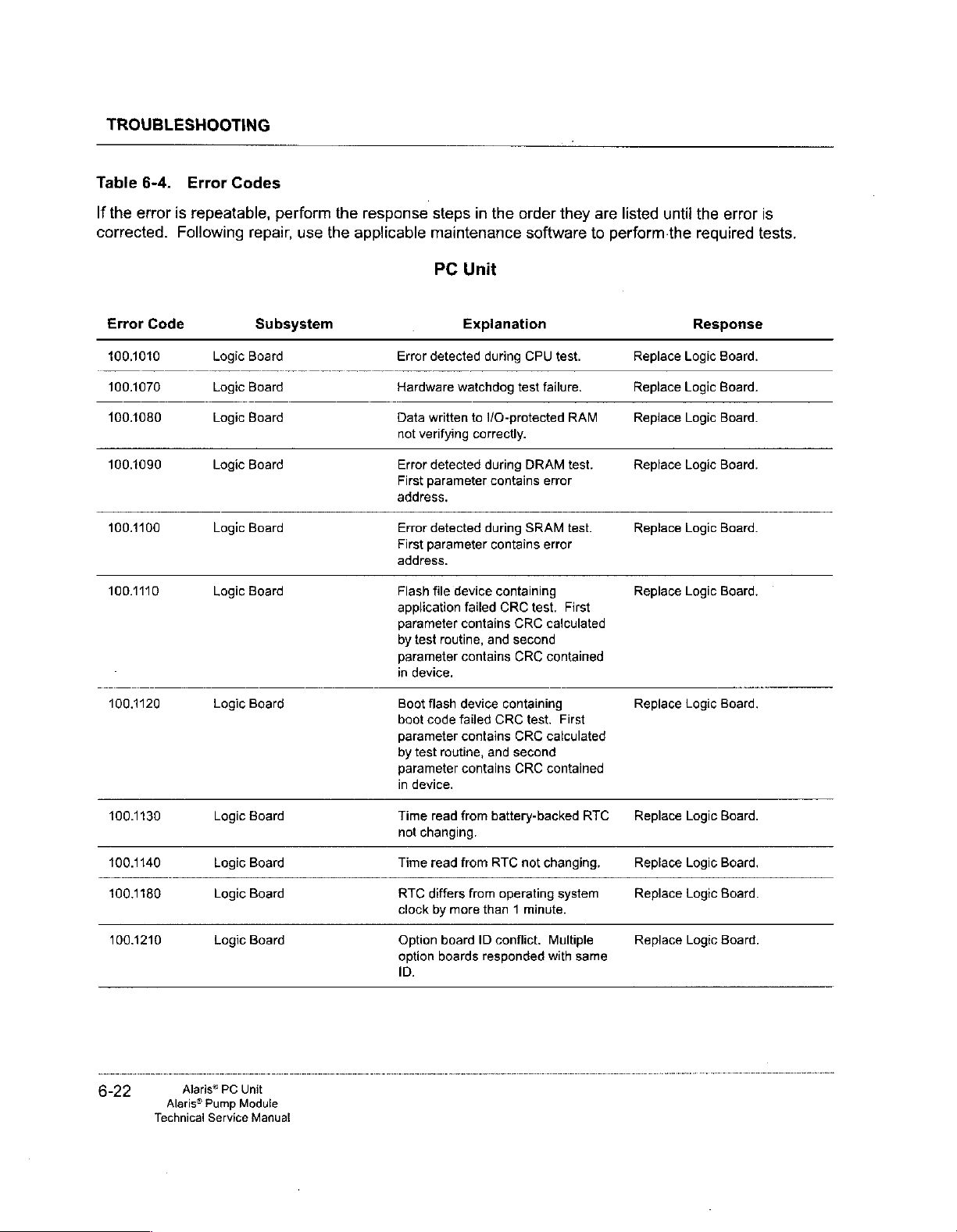
TROUBLESHOOTING
Table
6-4.
Error
If
the
error
is
repeatable,
corrected.
Error
100.1010
100.1070
100.1080
100.1090
100.1100
100.1110
100.1120
100.1130
100.1140
100.1180
100.1210
Following
Code
Codes
Logic
Logic
Logic
Logic
Logic
Logic
Logic
Logic
Logic
Logic
Logic
perform
repair,
Board
Board
Board
Board
Board
Board
Board
Board
Board
Board
Board
use
Subsystem
the
response
the
applicable
steps
maintenance
PC
Error
detected
Hardware
Data
not
Error
First
address.
Error
First
address.
Flash
application
parameter
by
parameter
in
Boot
boot
parameter
by
parameter
in
Time
hot
Time
RTC
clock
Option
option
ID.
written
verifying
detected
parameter
detected
parameter
file
device
test
routine,
device.
flash
code
test
routine,
device.
read
changing.
read
differs
by
more
board
boards
watchdog
failed
in
the
order
software
Unit
Explanation
during
CPU
test
to
1/O-protected
correctly.
during
DRAM
contains
during
SRAM
contains
cantaining
failed
CRC
contains
contains
device
contains
contains
from
from
CRC
and
second
CRC
containing
CRC
test.
CRC
and
second
CRC
battery-backed
RTC
not
from
operating
than 1 minute.
ID
conflict.
responded
they
test.
failure.
RAM
test.
error
test.
error
test, First
calculated
contained
First
calculated
contained
RTC — Replace
changing,
system
Multiple
with
same
are
to
perform
listed
until
Replace
Replace
Replace
Replace
Replace
Replace
Replace
Replace
Replace
Replace
the
Logic
Logic
Logic
Logic
Logic
Logic
Logic
Logic
Logic
Logic
Lagic
the
error
required
Response
Board.
Board.
Board.
Board.
Board.
Board.
Board.
Board.
Board,
Board.
Board.
is
tests.
6-22
Alaris®
Alaris®
Technical
PC
Pump
Module
Service
Unit
Manual
Page 2
TROUBLESHOOTING
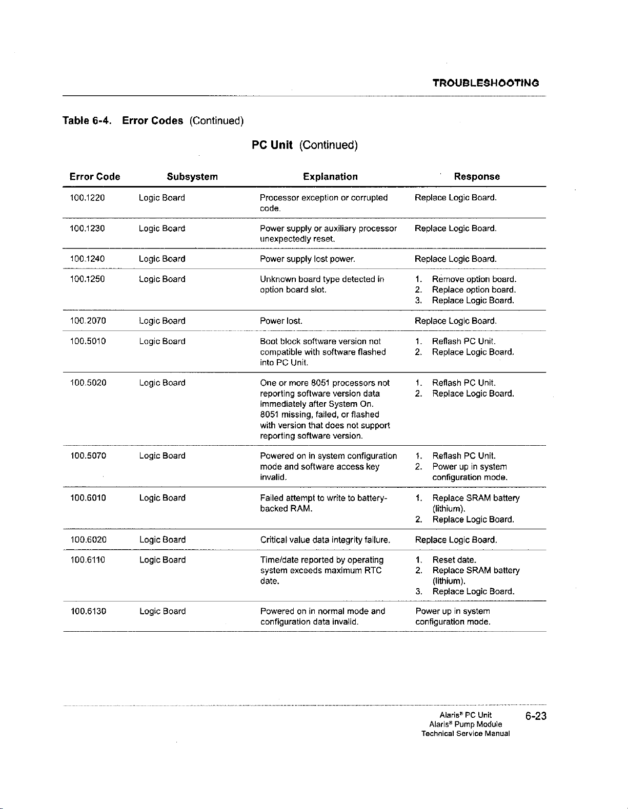
Table
Error
400.1220
100.1230
100.1240
100.1250
100.2070
100.5010
100.5020
100.5070
100.6010
100.6020
100.6110
100.6130
6-4.
Code
Error
Logic
Logic
Logic
Logic
Logic
Logic
Logic
Logic
Logic
Logic
Logic
Logic
Codes
Subsystem
Board
Board
Board
Board
Board
Board
Board
Board
Board
Board
Board
Board
(Continued)
PC
Unit
Processor
code.
Power
supply
unexpectedly
Power
supply
Unknown
option
board
Power
lost.
Boot
block
compatible
into
PC
Unit.
One
or
more
reporting
immediately
8051
missing,
with
version
reporting
Powered
mode
and
invalid.
Failed
attempt
backed
RAM.
Critical
value
Time/date
system
exceeds
date.
Powered
configuration
(Continued)
Explanation
exception
board
software
with
software
after
that
software
on
in
software
reported
on
in
or
auxiliary
reset.
lost
type
slot.
software
8051
failed,
does
system
to
write
data
maximum
normal
data
or
corrupted
power.
detected
version
processors
version
System
or
flashed
not
version.
configuration
access
to
integrity
by
operating
mode
invalid.
processor
in 1.
not
flashed
not
data
On.
support
key
battery-
failure.
RTC
and
Response
Replace
Replace
Replace
2.
3.
Replace
1.
2.
1.
2.
1.
2.
1.
2.
Replace
1.
2.
3.
Power
configuration
Logic
Logic
Logic
Remove
Repiace
Replace
Logic
Reflash
PC
Replace
Reflash
PC
Replace
Reflash
Power
PC
up
configuration
Replace
(lithium).
Replace
Logic
Reset
date.
Replace
(lithium).
Replace
up
in
system
Board.
Board.
Board.
option
option
Logic
Board.
Unit.
Lagic
Unit.
Logic
Unit.
in
system
mode.
SRAM
Logic
Board.
SRAM
Logic
mode.
board.
board.
Board.
Board.
Board.
battery
Board.
battery
Board.
Alaris®
PC
Alaris®
Technical
Pump
Service
Unit
Module
Manual
6-23
Page 3
TROUBLESHOOTING
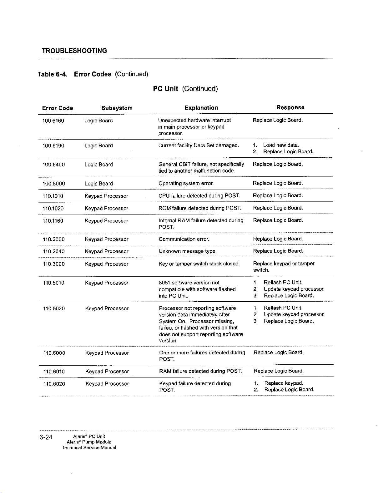
Table
6-4.
Error
Error
Code
100.6160
100.6190
100.6400
100.8000
110.1010
110.1020
110.1160
110.2000
110.2040
110.3000
110.5010
110.5020
110.6000
410.6010
110.6020
Codes
Logic
Logic
Logic
Logic
Keypad
Keypad
Keypad
Keypad
Keypad
Keypad
Keypad
Keypad
Keypad
Keypad
Keypad
(Continued)
PC
Unit
Subsystem
Board
Board
Board
Board
Processor
Processor
Processor
Processor
Processor
Processor
Processor
Processor Processor
Processor
Processor
Processor
Unexpected
in
main
processor.
Current
General
tied
Operating
CPU
ROM
Internal
POST,
Communication
Unknown
Key
8051
compatible
into
version
System
failed,
does
version.
One
POST.
RAM
Keypad
POST,
(Continued)
Explanation
hardware
processor
facility
CBIT
to
another
system
failure
detected
failure
detected
RAM
message
or
tamper
software
with
PC
Unit.
not
data
immediately
On.
Processor
or
flashed
not
support
or
more
failure
detected
failure
interrupt
or
keypad
Data
Set
failure,
not
malfunction
error.
during
during
failure
detected
error.
type.
switch
stuck
version
reporting
failures
not
software
with
version
reporting
detected
during
detected
missing,
damaged.
specifically
code.
POST,
POST,
during
closed.
flashed
software
after
that
software
during
POST.
during
Replace
1.
Load
2.
Replace
Replace
Replace
Replace
Replace
Replace
Replace
Replace
Replace
switch.
1.
Reflash
2.
Update
3.
Replace
1.
Reflash
2.
Update keypad
3.
Replace
Replace
Replace
1.
Replace
2.
Replace
Response
Logic
Board.
new
data.
Logic
Logic
Board.
Logic
Board,
Logic
Board.
Logic
Board.
Logic
Board.
Logic
Board.
Logic
Board.
keypad
PC
keypad
Logic
PC
Logic
Logic
Board.
Lagic
Board.
keypad.
Logic
Board.
or
tamper
Unit.
processor.
Board.
Unit.
processor.
Board.
Board.
6-24
Alaris®
Alaris®
Technical
PC
Pump
Service
Unit
Module
Manual
Page 4
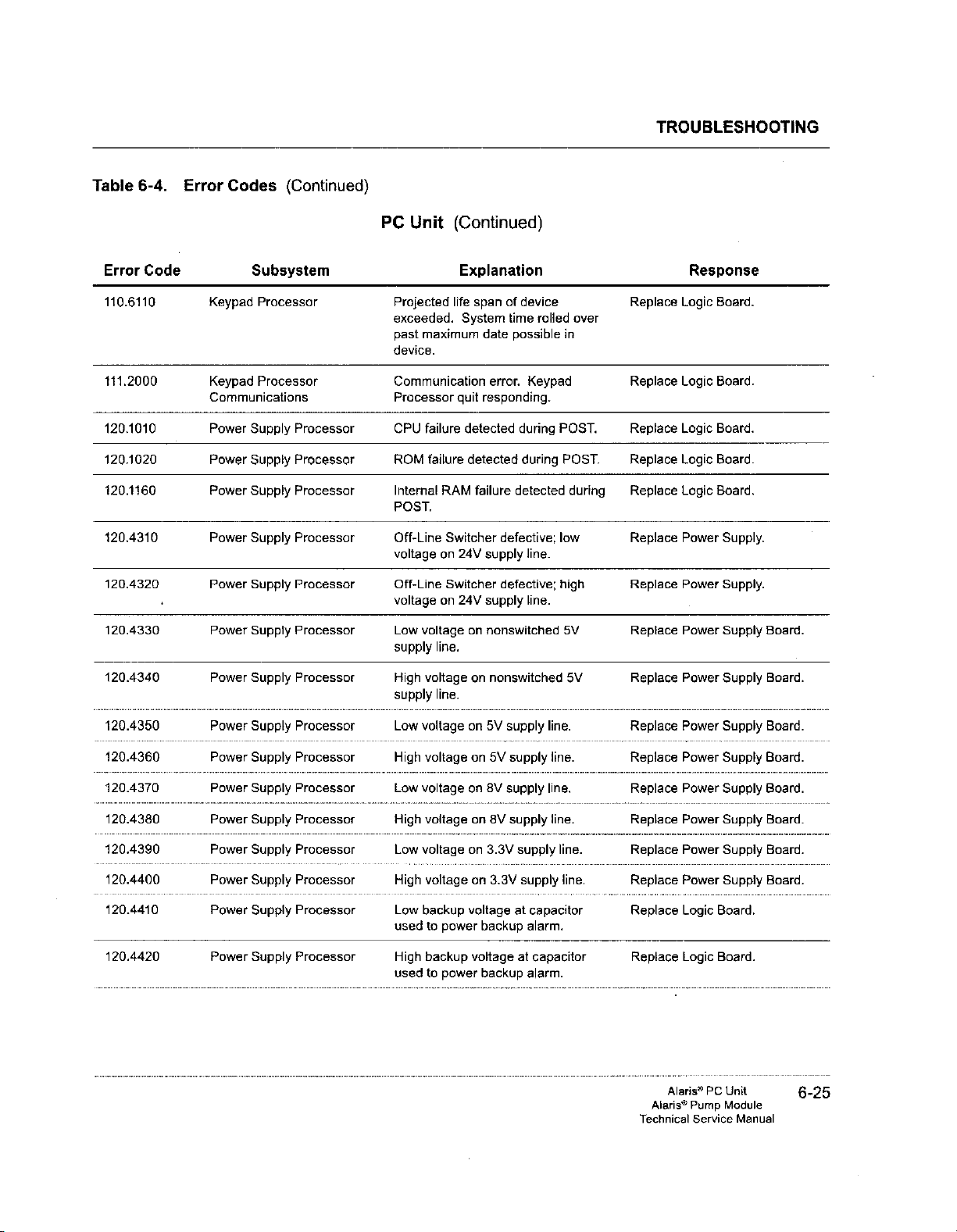
Table
Error
110.6110
111.2000
120.1010
120.1020
120.1460
120.4310
120.4320
120.4330
120.4340
120.4350
120.4360
120.4370
120.4380
120.4390
120.4400
120.4410
120.4420
6-4.
Code
Error
Codes
Keypad
Keypad
Communications
Power
Power
Power
Power
Power
Power
Power
Power
Power
Power
Power
Power
Power
Power
Power
(Continued)
Subsystem
Processor
Processor
Supply
Processor
Supply
Processor
Supply
Processor
Supply
Processor
Supply
Processor
Supply
Processor
Supply
Processor
Supply
Processor
Supply
Processor
Supply
Processor
Supply
Processor
Supply
Processor
Supply
Processor
Supply
Processor
Supply
Processor
PC
Unit
Projected
exceeded.
past
maximum
device.
Communication
Processor
CPU
failure
ROM
failure
Internal
RAM
POST.
Off-Line
voltage
on
Off-Line
voltage
on
Low
voltage
supply
line.
High
voltage
supply
line.
Low
voltage
High
voltage
Low
voltage
High
voltage
Low
voltage
High
voltage
Low
backup
used
to
power
High
backup
used
to
power
(Continued)
Explanation
life
span
of
System
quit
Switcher
24V
Switcher
24V
date
error.
responding.
detected
detected
failure
defective;
supply
defective;
supply
on
nonswitched
on
nonswitched
on
5V
supply
on
5V
on
8V
supply
on
8V
on
3.3V
on
3.3V
voltage
backup
voltage
backup
time
possible
during
detected
supply
supply
supply
at
at
device
rolled
Keypad
POST.
during
low
line.
high
line.
line.
line.
line.
line.
line.
supply
capacitor
alarm.
capacitor
alarm.
over
in
POST.
during
5V
5V
line.
TROUBLESHOOTING
Response
Replace
Replace
Replace
Replace
Replace
Replace
Replace
Replace
Replace
Replace
Replace
Replace
Replace
Replace
Replace
Replace
Replace
Logic
Logic
Logic
Logic
Logic
Power
Power
Power
Power
Power
Power
Power
Power
Power
Power
Logic
Logic
Board.
Board.
Board.
Board.
Board.
Supply.
Supply.
Supply
Supply
Supply
Supply
Supply
Supply
Supply
Supply
Board.
Board.
Board.
Board.
Board.
Board.
Board.
Board.
Board.
Board.
Alaris®
PC
Alaris®
Technical
Pump
Module
Service
Unit
Manual
6-25
Page 5
TROUBLESHOOTING
Table
Error
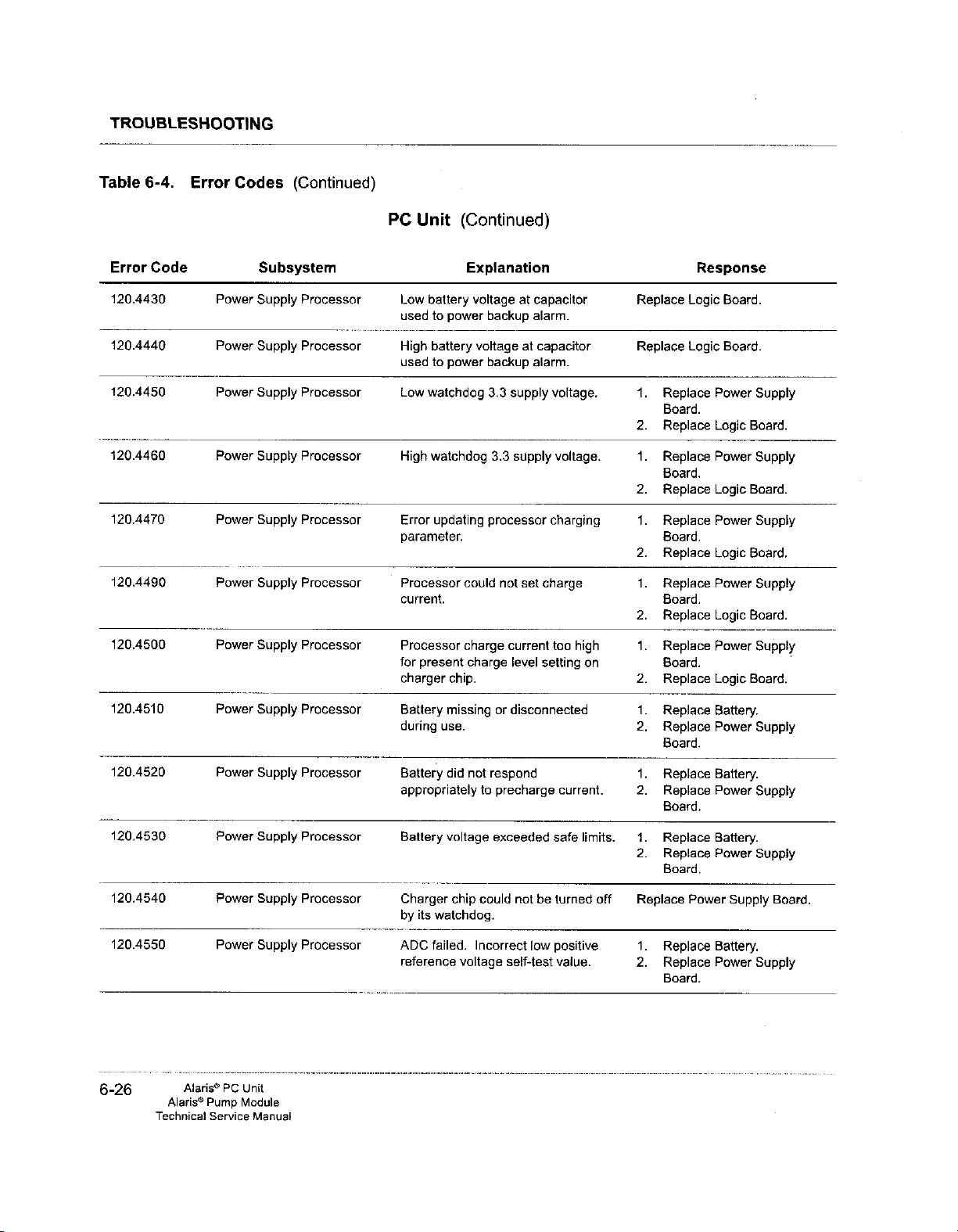
120.4430
120.4440
120.4450
120.4460
120.4470
120.4490
120.4500
120.4510
120.4520
120.4530
120.4540
120.4550
6-4.
Error
Code
Codes
Power
Power
Power
Power
Power
Power
Power
Power
Power
Power
Power
Power
(Continued)
Subsystem
Supply
Processor
Supply
Processor
Supply
Processor
Supply
Processor
Supply
Processor
Supply
Processor Processor
Supply
Processor
Supply
Processor
Supply
Processor
Supply
Processor
Supply
Processor
Supply
Processor
PC
Unit
Low
battery
used
to
power
High
battery
used
to
power
Low
watchdog
High
watchdog
Error
updating
parameter.
current.
Processor
for
present
charger
Battery
during
Battery
chip.
missing
use.
did
appropriately
Battery
voltage
Charger
by
its
watchdog.
ADC
failed.
reference
(Continued)
Explanation
voltage
at
capacitor
backup
alarm.
voltage
could
charge
charge
not
chip
Incorrect
voltage
backup
3.3
supply
3.3
supply
processor
not set
current
level
or
disconnected
respond
to
precharge
exceeded
could
not
self-test
at
alarm.
low
capacitor
voltage.
voltage.
charging
charge
too
high
setting
on
current.
safe
limits.
be
turned
positive
value.
off
Replace
Replace
1.
Replace
Board.
2.
Replace
1.
Replace
Board.
2.
Replace
1.
Replace
Board.
2.
Replace
1.
Replace
Board.
2.
Replace
1.
Replace
Board.
2.
Replace
1.
Replace
2.
Replace
Board.
1,
Replace
2.
Replace
Board.
1.
Replace
2.
Replace
Board,
Replace
1.
Replace
2.
Replace
Board.
Response
Logic
Board.
Logic
Board.
Power
Logic
Power
Logic
Power
Logic
Power
Logic
Power
Logic
Battery.
Power
Battery.
Power
Battery.
Power
Power
Supply
Battery.
Power
Supply
Board.
Supply
Board.
Supply
Board.
Supply
Board.
Supply
Board.
Supply
Supply
Supply
Board.
Supply
6-26
Alaris®
Alaris®
Technica!
PC
Pump
Service
Unit
Module
Manual
Page 6
Table
Error
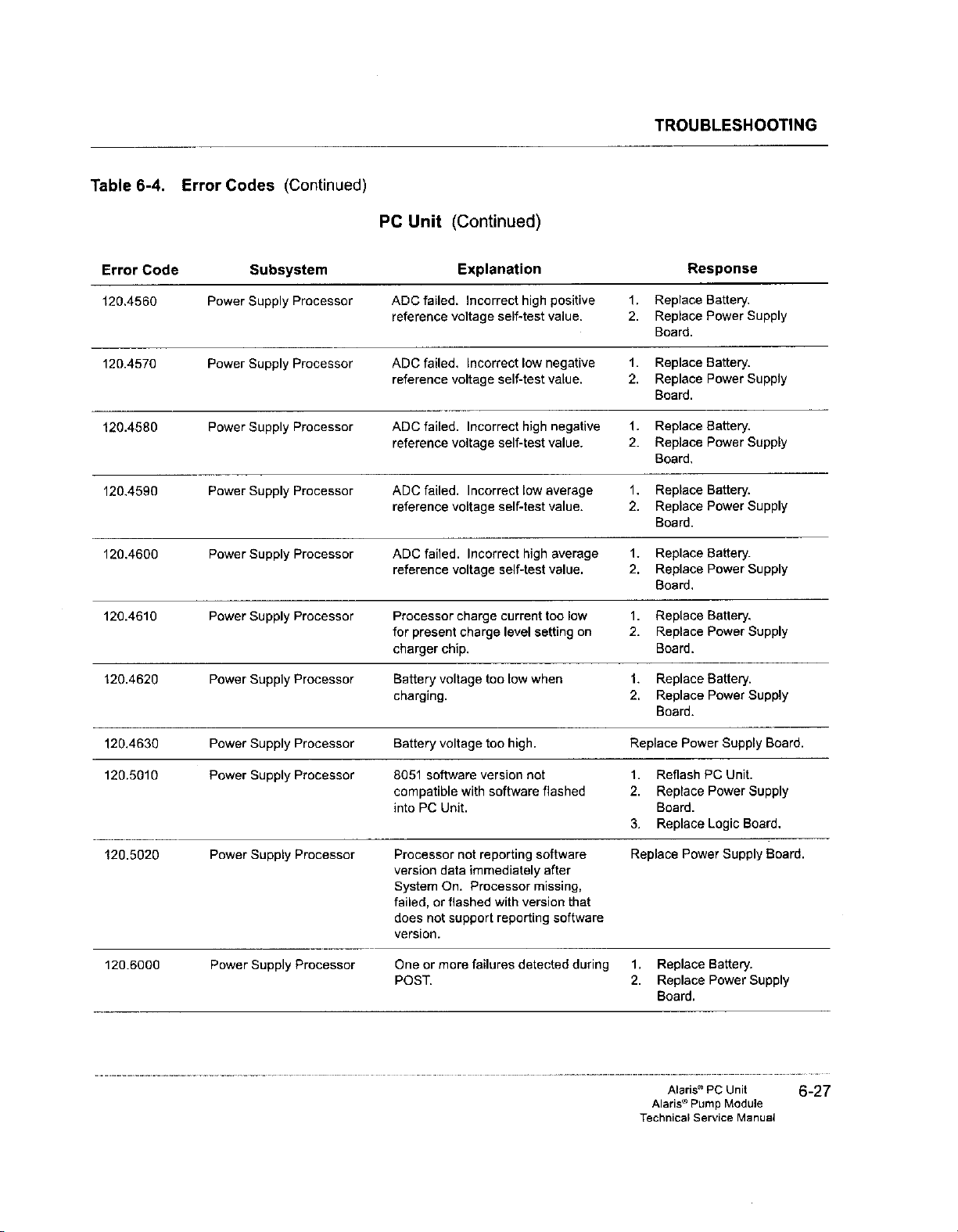
120.4560
120.4570
420.4580
120.4590
120.4600
120.4610
120.4620
120.4630
120,5010
420.5020
120.6000
6-4.
Code
Error
Power
Power
Power
Power
Power
Power
Power
Power
Power
Power
Power
Codes
Subsystem
Supply
Supply
Supply
Supply
Supply
Supply
Supply
Supply
Supply
Supply
Supply
(Continued)
Processor
Processor
Processor
Processor
Processor
Processor
Processor
Processor
Processor
Processor
Processor
PC
Unit
ADC
failed.
reference
ADC
failed.
reference
ADC
failed.
reference
ADC
failed.
reference
ADC
failed.
reference
Processor
for
present
charger
chip.
Battery voltage
charging.
Battery
voltage
8051
software
compatible
into
PC
Unit.
Processor
version
data
System
failed,
does
On.
or
not
flashed
support
version.
One
or
more
POST.
(Continued)
Explanation
Incorrect
voltage
Incorrect
voltage
Incorrect
voltage
Incorrect
voltage
Incorrect
voltage
charge
charge
with
not
immediately
Processor
failures
high
self-test
low
self-test
high
self-test
low
self-test
high
self-test
current
level
too
low
when
too
high.
version
not
software
reporting
with
version
reporting
detected
setting
flashed
software
missing,
positive
value.
negative
value.
negative
value.
average
value.
average
value.
too
low
on
after
that
software
during
TROUBLESHOOTING
Response
1.
Replace
2.
Replace
Board.
1.
Replace
2.
Replace
Board.
1.
Replace
2.
Replace
Board,
1.
Replace
2.
Replace
Board.
1.
Replace
2,
Replace
Board.
1.
Replace
2.
Replace
Board.
1.
Replace
2.
Replace
Board.
Replace
1.
Reflash
2.
Replace
Board.
3.
Replace
Replace
1.
Replace
2.
Replace
Board.
Battery.
Power
Battery.
Power
Battery.
Power
Battery.
Power
Battery.
Power
Battery.
Power
Battery.
Power
Power
PC
Power
Logic
Power
Battery.
Power
Supply
Supply
Supply
Supply
Supply
Supply
Supply
Supply
Unit.
Supply
Board,
Supply
Supply
Board.
Board.
Alaris®
PC
Alaris®
Technical
Pump
Service
Unit
Module
Manual
6-27
Page 7
TROUBLESHOOTING
Table
6-4.
Error
Error
Code
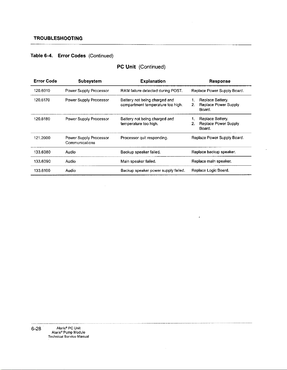
120.6010
120.6170
120.6180
121.2000
133.6080
133.6090
133.6100
Codes
Subsystem
Power
Supply
Power
Supply
Power
Supply
Power
Supply
Communications
Audio
Audio
Audio
(Continued)
Processor
Processor
Processor
Processor
PC
Unit
RAM
failure
Battery
compartment
Battery
temperature
Processor
Backup
Main
speaker
Backup
(Continued)
Explanation
detected
not
being
charged
temperature
not
being
charged
too
high.
quit
responding.
speaker
speaker
failed.
failed.
power
during
and
too
and
supply
POST.
Replace
1.
high.
2.
1.
2.
Replace
Replace
Replace
failed. | Replace
Response
Power
Replace
Replace
Board.
Replace
Replace
Board.
Power
backup
main
Logic
Supply
Battery.
Power
Supply
Battery.
Power
Supply
Supply
speaker.
speaker.
Board.
Board.
Board.
6-28
Alaris®
Alaris®
Technicai
PC
Pump
Service
Unit
Module
Manual
Page 8
TROUBLESHOOTING
Table
Error
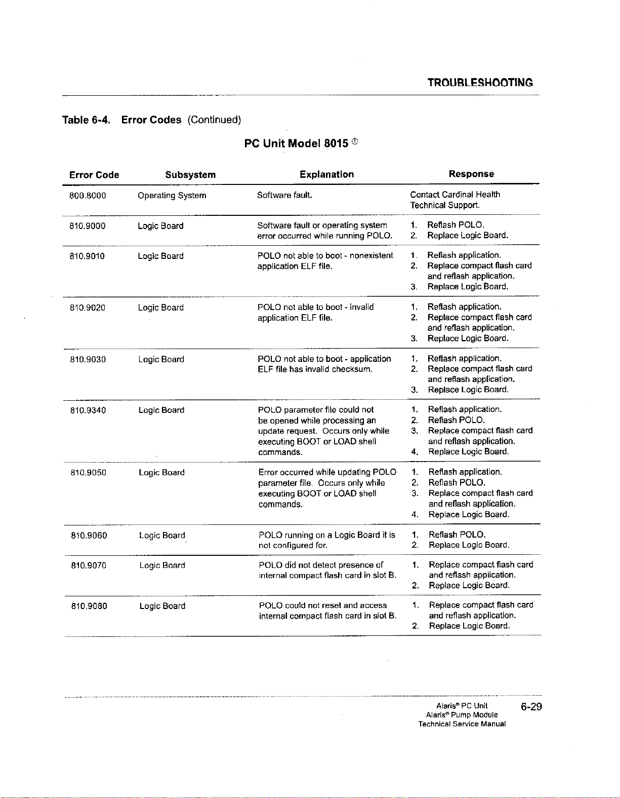
800.8000
810.9000
810.9010
810.9020
810.9030
810.9340
810.9050
810.9060
810.9070
810.9080
6-4.
Code
Error
Operating
Logic
Logic
Logic
Logic
Logic
Logic
Logic
Lagic
Logic
Codes
Subsystem
Board
Board
Board
Board
Board
Board
Board
Board
Board
(Continued)
System
PC
Unit
Software
Software
error
POLO
application
POLO
application
POLO
ELF
POLO
be
opened
update
executing
commands.
Error
parameter
executing
commands.
POLO
not
POLO
internal
POLO
internal
Model
Explanation
fault.
fault
occurred
not
able
ELF
not
able
ELF
not
able
file
has
invalid
parameter
while
request.
BOOT
occurred
file.
BOOT
running
configured
did
not
compact
could
not
compact
8015
©
or
operating
while
to
boot - nonexistent
system
running
file.
to
boot - invalid
file.
to
boot - application
checksum.
file
could
not
processing
Occurs
only
or
LOAD
shell
while
updating
Occurs
only
while
or
LOAD
shell
on a Logic
Board
for.
detect
presence
flash
card
in
reset
and
access
flash
card
in
POLO.
an
while
POLO
of
slot
slot
it
is
B.
B.
Contact
Cardinal
Technical
1.
Reflash
2.
Replace
1.
Reflash
2.
Replace
and
3.
Replace
1.
Reflash
2.
Replace
and
3.
Replace
1.
Reflash
2.
Replace
and
3.
Replace
1.
Reflash
2.
Reflash
3,
Replace
and
4.
Replace
1.
Reflash
.
Reflash
3.
Replace
and
4.
Replace
1.
Reflash
2.
Replace
1.
Replace
and
2.
Replace
1.
Replace
and
2.
Replace
Response
Support.
POLO.
Logic
application.
compact
reflash
application.
Logic
application.
compact
reflash
application.
Logic
application.
compact
reflash
application,
Logic
application.
POLO.
compact
reflash
application.
Logic
application.
POLO.
compact
reflash
application.
Logic
POLO.
Logic
compact
reflash
application.
Logic
compact
reflash
Logic
Health
Board.
flash
card
Board.
flash
card
Board.
flash
card
Board.
flash
card
Board.
flash
card
Board.
Board.
flash
card
Board.
flash
card
application.
Board.
Alaris®
PC
Alaris®
Technical
Pump
Service
Unit
Module
Manual
6-29
Page 9

TROUBLESHOOTING
Table
6-4.
Error
Error
Code
810.9090
810.9100
810.9105
810.9110
810.9120
810,9130
810.9135
810.9440
810.9145
810.9150
810.9160
Codes
Lagic
Logic
Logic
Logic
Logic
Logic
Logic
Logic
Logic
Logic
Logic
(Continued)
Subsystem
Board
Board
Board
Board
Board
Board
Board
Board
Board
Board
Board
PC
Unit
Model
8015 © (Continued)
Explanation
Compact
disk
Compact
supported
Wireless
POLO.
POLO
driver
compact
POLO
a
flash
Configuration
compact
incorrect,
Configuration
wireless
Function
flash
Function
card
POLO
directory
Watchdog
POLO
type
could
for a disk
could
disk
type card
card
card
incorrect.
not
was
flash
card.
flash
by
card
flash
slots.
flash
card
|D
tuple
in
slot B incorrect.
ID
tuple
able
in
internal
timer
booting
card
card
POLO.
not
supported
not
initialize
type card
card
not
mount
in
one
tuple
card
tuple
slot.
read
read
to
create
test
in
slot B not
in
slot B not
ATA
in
slots.
volume
of
compact
read
from
in
slot
B
read
from
from
compact
from
wireless
POLO
FFX
file
failed
while
an
application.
a 1.
by
one
of
on
cardin
system.
Replace
and
2.
Replace
1.
Replace
and
2.
Replace
1.
Replace
2.
Replace
extension
3.
Replace
1.
Replace
and
2.
Replace
1.
Replace
and
2.
Replace
1.
Replace
and
2.
Replace
1.
Replace
2.
Replace
extension
3.
Replace
1.
Replace
and
2.
Replace
1.
Replace
2.
Replace
extension
3.
Replace
1.
Reflash
2.
Replace
Replace
Response
compact
reflash
application.
Logic
compact
reflash
application.
Logic
wireless
wireless
board.
Logic
compact
reflash
application.
Logic
compact
reflash
application,
Logic
compact
reflash
application.
Logic
wireless
wireless
board.
Logic
compact
reflash
application.
Logic
wireless
wireless
board,
Logic
POLO.
Logic
Logic
Board.
flash
Board.
flash
Board.
card.
card
Board.
flash
Board.
flash
Board.
flash
Board.
card.
card
Board.
flash
Board.
card.
card
Board.
Board.
card
card
card
card
card
card
6-30
Alaris®
Alaris®
Technical
PC
Pump
Module
Service
Unit
Manual
Page 10

TROUBLESHOOTING
Table
Error
810.9170
810.9175
©
POLO
6-4.
Code
Error
refers
Codes
Logic
Logic
to
the
(Continued)
Subsystem
Board
Board
operating
PC
system
Unit
Model
software
POLO
from
POLO
from
8015 © (Continued)
Explanation
unable
to
read
attribute
compact
wireless
after
unable
boot
flash card.
to
read
attribute
card.
up
(power
tuples
tuples
up
sequence).
1.
2.
1,
2.
3.
Response
Replace
and
reflash
Replace
Replace
Replace
extension
Replace
compact
application.
Logic
Board.
wireless
wireless
Logic
card.
card
board.
Board.
flash
card
Alaris®
Alaris®
Technical
PC
Pump
Module
Service
Unit
Manual
6-31
Page 11

TROUBLESHOOTING
Table
6-4.
Error
Codes
(Continued)
Error
200.1010
200.1030
200.1040
200.1060
200.1070
200.1110
200.1120
200.1200
200.4160
200.5010
200.5020
200.5030
200.5040
200.6120
210.1010
210.1020
Code
Subsystem
Logic
Board
Logic
Board
Logic
Board
Logic
Board
Lagic
Board
Logic
Board
Logic
Board
Logic
Board
Logic
Board Motor
Logic
Board
Logic
Board
Logic
Board
Logic
Board
Logic
Board
Keypad
Keypad
Processor
Processor
Pump
Module
Explanation
Error
detected
64K
to
Unable
chip
used
Watchdog
Hardware watchdog
Flash
file
application
Boot
flash
code
failed
Uninitialized
Default
shutoff
failed.
Boot
block
compatible
into
Pump
One
or
reporting
immediately
8051
missing,
with
version
reporting
Serial
number
Module
Pump
Module
compatible
into
PC
Critical
CPU
failure
ROM
failure
during
flash
file
DRAM
to
write
into
for
logging.
failure.
device
containing
failed
CRC
file
device
CRC
test.
interrupt
handler
called.
safety switch
software
with
software
Module.
more
8051
software
after
failed,
that
does
software
reported
not a recognized
software
with
software
Unit.
value
data
detected
detected
CPU
test
flash
memory
test
failure.
test.
containing
occurred.
version
flashed
processors
version
System
or
flashed
not
On.
support
version.
by
type.
version
flashed
integrity
during
during
test.
failed.
boot
test
not
not
data
Pump
not
failure.
POST.
POST.
Replace
Replace
Replace
Replace
Replace
Replace
Replace
Replace
Replace
1.
Reflash
2.
Replace
Replace
Replace
Reflash
Module.
Replace
Replace
Replace
Response
Logic
Board.
Logic
Board.
Logic
Board.
Logic
Board.
Logic
Board.
Logic
Board.
Logic
Board.
Logic
Board.
Logic
Board.
Pump
Logic
Logic
Board.
Logic
Board.
PC
Unit
Logic
Board.
Logic
Board.
Logic
Board.
Module.
Board.
or
Pump
6-32
Alaris®
Alaris®
Technical
PC
Pump
Service
Unit
Module
Manual
Page 12

Table
6-4.
Error
Codes
TROUBLESHOOTING
(Continued)
Error
210.1160
210.2040
210.4040
210.5010
210.5020
210.6000
210.6010
210.6020
210.6030
210.6040
211.2000
220.1000
220.1010
220.1020
220.1160
Code
Subsystem
Keypad
Keypad
Keypad
Keypad
Keypad
Keypad
Processor
Processor
Processor
Processor
Processor
Processor
Keypad
Keypad
Keypad
Keypad
Keypad
Processor
Processor
Processor
Processor
Processor
Communications
Safety
Processor
Safety
Processor
Safety
Processor
Safety
Processor
Pump
Module
Internal
POST.
Response
not
Clear
detected
8051
compatible
into
Processor
version
System
failed,
does
version,
One
POST.
RAM
expected.
Display
during
software
Pump
data
On.
or
flashed
not
support
or
more
RAM
failure
Keypad
failure
POST.
Alarm
LED
POST.
Display
failure
POST.
Unspecified
Internal
error.
CPU
failure
ROM
failure
Internal
RAM
POST.
(Continued)
Explanation
failure
detected
message
with
Module.
not
failure
received
BSYNC
failure
POST.
version
software
reporting
immediately
Processor
with
version
reporting
failures
detected
detected
during
detected
detected
detected
communication
detected
detected
failure
during
detected
not
flashed
software
after
missing,
software
during
during
during
during
during
when
that
during
POST.
error.
POST.
POST.
during
Replace
Replace
Replace
Reflash
Replace
Replace
Replace
Replace
Replace
Replace
Replace
Replace
Replace
Replace
Replace
Response
Logic
Board.
Logic
Board,
Logic
Board.
PC
Unit.
Logic
Board.
Logic
Board.
Logic
Board.
Keypad.
defective
defective
Logic
Board.
Logic
Board.
Logic
Board.
Logic
Board.
Logic
Board.
alarm
LED.
display.
Alaris®
Alaris®
Technical
PC
Pump
Module
Service
Unit
Manual
6-33
Page 13

TROUBLESHOOTING
Table
6-4.
Error
Codes
(Continued)
Error
220.5010
220.5020
220.6000
220.6010
221.2000
221.2010
221.2020
221.2030
221.2040
221.2050
221.2060
222.1000
222.2030
Code
Subsystem
Safety
Processor
Safety
Processor
Safety
Processor
Safety
Processor
Safety
Processor
Communications
Safety
Processor
Communications
Safety
Processor
Communications
Safety
Processor
Communications
Safety
Processor
Communications
Safety
Processor
Communications
Safety
Processor
Communications
Safety
Processor
Check
Safety
Processor
Check
Cross-
Cross-
Pump
Module
Explanation
8051
software
compatible
into
Processor
version
System
failed,
does
version.
One
POST.
RAM
Unspecified
Timely
message
Incorrect
received.
Corrupted
received.
Response
not
Received
interpreted.
Not
a
timely
Measured
action
undetermined.
Corrupted
received.
with
Pump
Module,
not
data
On.
or
flashed
not
support
or
more
failure
response
not
response
response
message
expected.
command
receiving
manner.
illegal
by
main
response
(Continued)
version
reporting
immediately
Processor
failures
detected
communication
received.
heartbeat
not
software
flashed
software
after
missing,
with
version
reporting
software
detected
during
to
watchdog
message
message
received
that
cannot
messages
or
inaccurate
processor - reason
message
that
during
POST,
error.
when
be
in
Replace
Replace
Replace
Replace
Replace
Replace
Replace
Replace
Replace
Replace
Replace
Replace
Replace
Response
Logic
Board.
Logic
Board,
Logic
Board.
Logic
Board.
Logic
Board.
Logic
Board.
Logic
Board.
Logic
Board.
Logic
Board.
Logic
Board.
Logic
Board.
Logic
Board.
Logic
Board.
6-34
Alaris®
Alaris?
Technical
PC
Pump
Module
Service
Unit
Manual
Page 14

Table
6-4.
Error
Codes
TROUBLESHOOTING
(Continued)
Error
222.2040
222.4010
222.4020
222,4030
222.4040
222.4050
222.4060
222.4160
Code
Safety
Check
Safety
Check
Safety
Check
Safety
Check
Safety
Check
Safety
Check
Safety
Check
Safety
Check
Subsystem
Processor
Processor
Processor
Processor
Processor
Processor
Processor
Processor
Cross-
Cross-
Cross-
Cross-
Cross-
Cross-
Cross-
Cross-
Pump
Module
Explanation
Response
not
High
Low
Motor
Detected
motor
Excessive
Over-infusion
{infusion
Motor
failed.
message
expected.
infusion
infusion
stall
detected.
encoder
pulses.
ait-in-line
past
shutoff
(Continued)
received
rate
detected.
rate
detected
out
of
sync
detected.
state
detected
VTBI
limit).
safety
switch
:
test
when
with
Replace
1.
Replace
(motor
this
2.
Replace
Board.
3.
Replace
1.
Replace
{motor
this
2.
Replace
Board.
3.
Replace
1.
Replace
(motor
this
2.
Replace
Board.
3.
Replace
1.
Replace
(motor
this
2.
Replace
1.
Replace
2.
Replace
1.
Replace
(motor
this
2.
Replace
Board.
3.
Replace
Replace
Response
Logic
Board.
AIL
Assembly
encoder
assembly).
Motor
Controller
Logic
Board.
AIL
Assembly
encoder
assembly).
Motor
Controller
Logic
Board.
AIL
Assembly
encoder
assembly).
Motor
Controller
Logic
Board.
AIL
Assembly
encoder
assembly).
Logic
Board.
AIL
Assembly.
Logic
Board.
AlL
Assembly
encoder
assembly).
Motor
Logic
Board.
Logic
Board.
is
part
of
is
part
of
is
part
of
is
part
of
is
part
of
Controller
Alaris®
PC
Alaris®
Technical
Pump
Service
Unit
Module
Manual
6-35
Page 15

TROUBLESHOOTING
Table
6-4.
Error
Codes
(Continued)
Error
222.4170
222.4180
222.4190
222.4200
240.4140
240.4150
241.4140
241.4150
242.4000
Code
Subsystem
Safety
Processor
Check
Safety
Processor
Check
Safety
Processor
Check
Safety
Processor
Check
Bottle-Side
Pressure
Sensor
Bottle-Side
Sensor
Patient-Side
Sensor
Patient-Side
Pressure
Pressure
Pressure
Sensor
Motor/Encoder
Cross-
Cross-
Cross-
Cross-
Pump
*
Module
Detected
of-range.
include:
burst
rate
mode
flag,
in-line
flag.
Improper
detected
Received
switch
when
or
to
close
Motor
activity
should
be
Voltage
broken.
Voltage
broken.
Voltage
broken.
Voltage
broken.
Encoder
software
whether
slow
or
(Continued)
Explanation
infusion
Parameter
rate,
VTBI,
threshold,
infuse
door
and/or
during
infusion.
command
switch
when
detected
idle.
too
low.
too
high.
too
low.
too high.
feature
unable
mechanism
too
fast.
parameter
possibilities
AIL
limit,
maintenance
all
flag,
flow
to
open
is
already
already
closed.
when
Sensor
may
Sensor
Sensor
may
Sensor
not
recognized;
to
determine
rotation
out-
VPMR,
check
stop
safety
motor
be
may
be
may
is
air-
state
open,
be
be
too
Replace
1.
Replace
2.
Replace
Replace
1.
Replace
(motor
this
2.
Replace
Board.
3.
Replace
Replace
sensor.
Replace
sensor.
Replace
sensor.
Replace
sensor.
1.
Replace
(motor
this
2.
Replace
Board.
3.
Replace
Response
Logic
Board.
AIL
Assembly.
Door
Assembly.
Logic
Board.
AIL
Assembly
encoder
assembly).
Motor
Controller
Logic
Board.
bottle-side
bottle-side
pressure
pressure
patient-side
patient-side
AJL
Assembly
encoder
assembly).
Motor
Controller
Logic
Board.
is
part
pressure
pressure
is
part
of
of
6-36
Alaris®
Alaris?
Technical
PC
Pump
Module
Service
Unit
Manual
Page 16

Table
6-4.
Error
Codes
TROUBLESHOOTING
(Continued)
Error
242.4010
242,4020
242.4030
243.4070
244,3020
245.3020
260.4080
260.4090
260.4100
Code
Subsystem
Motor/Encoder
Motor/Encoder
Motor/Encoder
Air-in-Line
Safety
Clamp
Door
Power
Supply
Power
Supply
Power
Supply
Pump
Module
Fluid
delivery
quickly
(infusion
Fluid
delivery
quickly
(infusion
Motor
stall
Failed
self
Safety
clamp
(CLOSED)
unpowered
unsafe
(OPEN)
Door sensor
(CLOSED)
unpowered
unsafe
(OPEN)
3.3V
AD
voltage
than
voltage
3.3V
AD
voltage
than
voltage
5V
AD
voltage
than
voltage
(Continued)
Explanation
mechanism
rate
high).
mechanism
rate
low).
detected.
test.
read
in
safe
when
sensor was
and
should
state.
read
in
safe
when
sensor
and
should
state.
at
least
in
specification.
at
least
in
specification,
at
least
in
specification.
turning
turning
state
have
state
was
have
8.4%
8.4%
8.4%
read
read
lower
higher
lower
too
too
in
in
1.
Replace
(motor
this
2,
Replace
Board.
3.
Replace
1.
Replace
(motor
this
2.
Replace
Board,
3.
Replace
1.
Ensure
securely
2.
Replace
(motor
this
3.
Replace
Board.
4.
Replace
Replace
1.
Replace
(safety
assembly).
2.
Replace
1.
Replace
(door
assembly).
2.
Replace
Replace
Replace
Replace
Response
Ail
Assembly
encoder
assembly).
Motor
Logic
AlL
Assembly
encoder
assembly).
Motor
Logic
motor
connected.
AIL
Assembly
encoder
assembly).
Motor
Logic
AIL
Assembly.
AIL
Assembly
clamp
Logic
AIL
Assembly
sensor
is
Logic
Motor
Controller
Motor
Controller
Logic
Board.
is
part
of
Controller
Board.
is
part
of
Controller
Board.
connector
is
part
of
Controller
Board.
is
part
of
Board.
part
of
this
Board.
Board.
Board.
is
this
Alaris®
PC
Alaris®
Technical
Unit
Pump
Module
Service
Manual
6-37
Page 17

TROUBLESHOOTING
Table
6-4.
Error
Codes
(Continued)
Error
260.4110
260.4120
260.4130
2XX.2080
2XX.2090
2XX.3000
2XX.4700
2XX.4710
2XX.5080
2XX.6400
Code
Subsystem
Power
Supply
Power
Supply
Power
Supply
Communications
Communications
Keypad
ADC
ADC
Communications
Logic
Board
Processor
Board
or
Display
Pump
5V
than
Pressure
least
specification.
Pressure
8.4%
specification.
Module
sequence.
Seventh
Keypad
ADC
specified
ADC
within
Module's
by
General
tied
Module
AD
voltage
voltage
Sensor
8.4%
Sensor
higher
poli
or
key
failed
time.
failed
specified
version
PC
Unit
CBIT
to
another
(Continued)
Explanation
at
least
8.4%
higher
in
specification.
voltage
at
lower
than
voltage
voltage
at
least
than
voltage
in
not
in
odd/even
greater
module
stuck
closed.
to
calibrate
to
complete a conversion
time.
data
within
specified
failure,
malfunction
attached.
itself
within
not
validated
time.
not
specifically
code.
in
Replace
Replace
Replace
1.
Replace
2.
Replace
None
Replace
Replace
Replace
None
Replace
Board.
Response
Logic
Board.
Logic
Board.
Logic
Board.
IU!
Logic
Keypad.
Logic
Board.
Logic
Board.
Logic
Board
connectors.
Board.
or
Display
6-38
Alaris®
Alaris?
Technical
PC
Unit
Pump
Module
Service
Manual
Page 18

Table
Error
350.6600
350.6630
350.6680
351.6610
351.6660
351.6720
351.6730
351.6740
351.6750
351.6760
351.6770
352.6640
352.6700
353.6650
354.6670
6-4.
Code
Error
Codes
(Continued)
PCA
Subsystem
Logic
Board
Force
Sensor
Logic
Board
Motor
Watchdog
Linear
Sensor
Motor Motor
Logic
Board
Motor
Logic
Board
Engagement
Engagement
Module
Pressure
Logic
Module)
Force
Logic
Force
Linear
Pressure
(Syringe
Sensing
Board
Sensor
Board
Sensor
Sensor
Sensing
Module)
Nut
Nut
Disc
(Syringe
Disc
Module
Watchdog
Pressure
sensor.
Timer
sync.
Unexpected
Movement
in
Linear
expected
too
Too
sample.
Nut
lever
Attempt
before
Calibration
calibrated.
Pressure
failed
Force
outside
Force
Linear
outside
Pressure
acceptable
and
bases;
steps
slow.
many
not
engaged
not
to
engaging.
during
sensor
acceptable
sensor
Sensor
acceptable
Syringe
Explanation
circuit
failed
not
tracked
clock
frequency
countdown
error;
predicted
Sensor
inconsistent
position.
accumulating
steps
in
motor
during
opened.
engage
sensing
sensor
flag
not
POST.
output
circuit
output
range.
nut
set.
disc
output
Module
POST.
by
force
interrupt.
step
infusion;
timed
Module
circuit
is
Zero
range.
check
is
zero
range.
is
out
change
with
too
fast
out
not
test
or
is
failure.
or
is
outside
of
or
TROUBLESHOOTING
Response
Replace
Replace
Assembly.
Replace
Replace
Board.
Replace
Replace
Board.
Replace
Board.
Replace
nut
engagement
Replace
nut
engagement
Calibrate,
Replace
and/or
Replace
Assembly,
Replace
Sensor
Replace
Replace
Logic
Force
Logic
Motor
Linear
Motor
Motor
Logic
engagement
nut.
Logic
engagement
nut.
as
required.
pressure
Logic
Board.
Force
Logic
Assembly.
Linear
pressure
©
Board.
Sensor
Board.
and/or
Logic
Sensor.
and/or
Logic
and/or
Logic
Board, and/or
sensor
or
Board,
and/or
sensor
or
sensing
Sensor
Board
Sensor.
sensing
or
disc
Force
disc.
Alaris®
PC
Alaris®
Technical
Pump
Service
Unit
Module
Manual
6-39
Page 19

TROUBLESHOOTING
Table
6-4.
Error
Error
Code
354.6690
356.6710
356.6780
3XX.2080
3XX.2090
3XX.3000
3XX.4700
3XX.4710
3XX.5080
3XX.6400
3XX.7200
3XX.7210
3XX.7220
©
Replacing
version
Service
the
or
7
Manual
Codes
(Continued)
PCA
Module
and
Syringe
Subsystem
Logic
Board
Digital
Sensor
PCA
Handset
Communications
Communications
Keypad Keypad
Logic
Board
Logic
Board
Communications
Display
Board
Linear
Sensor
Logic
Board
Linear
Sensor
Logic
Board
Linear
Sensor
Force
earlier
for
Sensor
software
further
Assembly
must
information.
or
performed
be
Pressure
acceptable
Digital
range
System
stuck
Module
sequence.
Seventh
ADC
specified
ADC
within
Module's
by
PC
General
tied
to
Plunger
readings
wiper
with
resistive
Plunger
module's
sensor
contamination
1.08
Motor
contact
Logic
Explanation
Sensor
range.
sensor
outside
during
no-power
detected
at
power-up.
poll
not
or
greater
key
stuck
failed
to
calibrate
time.
failed
to
complete a conversion
specified
version
Unit
within
CBIT
failure,
another
position
indicate
is
making
surface
position
calibrated
readings
mm
of
mation
running
lower
Board
the
at
and
mechanical
Assembly
depot.
Module
current
outside
acceptable
test.
PCA
Handset
in
odd/even
module
closed.
itself
time.
data
not
validated
specified
not
specifically
malfunction
Linear
Sensor
potentiometer
intermittent
(log
only).
sampler
indicate
continuously
cleared
flag
because
possible
(log
only).
plunger
Reference
stop.
in
(Continued)
Replace
Pressure
Replace
Key
attached.
within
time.
code.
contact
for
about
PCA
a
to
Module
the
Replace
1.
2.
None
Replace
Replace
Replace
None
Replace
Board.
Replace
1.
2.
3.
1.
2.
3.
PCA
Response
Logic
Sensor.
digital
PCA
Replace
Replace
Keypad.
Logic
Logic
Logic
Linear
Calibrate
Replace
Replace
Calibrate
Replace
Replace
Syringe
or
Module
Board
sensor.
Handset.
IUi
connectors.
Logic
Board.
Board.
Board.
Board
Sensor.
Linear
Linear
Sensor.
Logic
Board.
Linear
Linear
Sensor.
Logic
Board.
Module
Syringe
/
?
or
or
Display
Sensor.
Sensor.
with
Module
6-40
Alaris®
Alaris®
Technical
PC
Pump
Module
Service
Unit
Manual
Page 20

Table
6-4.
Error
Codes
Error
Code
Subsystem
4XX.2080 Communications
4XX.2090 Communications
4XX.3000
4XX.5080
4XX.6200
4XX.6210
4XX.6220
4XX.6230
4XX.6240
4XX.6300
4XX.6310
4XX.6320
4XX.6330
4XX.6400
4XX.6500
Keypad
Processor
Communications
SpO,
Board
SpO,
Board
SpO,
Board
SpO,
Board
SpO,
Board
Display
Board
Display
Board
Display
Board
Display
Board
Display
Board
SpO,
Board
(Continued)
SpO,
Module
Explanation
Module
poll
not
sequence.
Seventh
Keypad
Module's
by
Failed
or
key
version
PC
Unit
“continuous
greater
stuck
within
Communications
Configurations
Received
Missing
Shorted
value
sensor
segment
display.
Open
Segment
Display.
Shorted
Open
General
tied
Serious
alarm
to
another
alarm
LED.
CBIT
module
in
odd/even
module
closed.
data
not
specified
built-in
error.
error.
"out
of
range”.
status.
in
7-segment
in
7-Segment
LED.
failure,
not
malfunction
error.
attached.
validated
time.
tests".
specifically
code.
TROUBLESHOOTING
Response
1.
Replace
2.
Replace
None
Replace
None
1.
Cycle
2.
Replace
1.
Cycle
2.
Replace
3.
Replace
Logic
Board.
4.
Replace
1.
Cycle
2.
Replace
1.
Replace
2.
Cycle
3.
Replace
1.
Replace
2.
Cycle
3.
Replace
Replace
Replace
Replace
Replace
Replace
Replace
IU!
Logic
Keypad.
power.
SpO,
power.
SpO,
cable
Board
Logic
power.
SpO,
Sensor.
power.
SpO,
Sensor.
power.
SpO,
Display
Display
Display
Display
Display
SpO,
Board.
connectors.
Board.
Board.
Board.
between
and
SpO,
Board.
Board.
Board.
Board.
Board.
Board.
Board.
Board.
Board.
Alaris®
PC
Alaris®
Pump
Technical
Unit
Module
Service
Manual
6-41
Page 21

TROUBLESHOOTING
Table
6-4.
Error
Error
Code
4XX.6510
4XX.6520
4XX.6530
4XX.6560
4XX.6580
Codes
Spo,
SpO,
SpO,
SpO,
SpO,
(Continued)
Subsystem
Board
Board
Board
Board
Board
SpO,
Module
Module
cycled.
Module
Transient
Power-on
Unknown
error
error
(Continued)
Explanation
requires
requires
error.
test
error.
error,
power
it
to
be
to
be
reset.
Replace
Replace
Replace
Replace
Replace
Response
SpO,
Board.
SpO,
Board.
SpO,
Board.
SpO,
Board.
SpO,
Board.
6-42
Alaris®
Alaris?
Technical
PC
Pump
Service
Unit
Module
Manual
Page 22

TROUBLESHOOTING
Table
Error
5XX.2080
5XX.2090
5XX.3000
5XX.5080
5XX.6200
5XX.6210
5XX.6220
5XX.6230
5XX.6240
5XX.6400
5XX.6500
6-4.
Code
Error
Codes
Communications
Communications
Keypad
Communications
EtCO,
EtCO,
EtCO,
EtCO,
EtCO,
Display
EtCO,
(Continued)
Subsystem
Processor
Board
Board
Board
Board
Board
Board
Board
EtCO,
Module
Explanation
Module
sequence.
Seventh
Keypad
Module's
by
PC
Unit
Failed
continuous
poil
not
or
greater
key
stuck
version
within
Communications
Configuration
Received
Missing
General
tied
to
EtCO,
perform
value
sensor
CBIT
another
Board
an
action.
error.
failure,
malfunction
took
in
odd/even
module
closed.
data
specified
built-in
error.
out
of
range.
status.
not
too
long
attached.
not
validated
time.
tests.
specifically
code.
to
1.
Replace
2.
Replace
None
Replace
None
Replace
1.
Replace
Replace
Logic
Board.
3.
Replace
Replace
1.
Replace
Disposable
2.
Replace
1.
Replace
Disposable
2.
Replace
Replace
Replace
Response
IU!
Logic
Keypad.
EtCO,
Board,
EtCO,
cable
Board
Logic
EtCO,
Board.
Microstream®
EtCO,
Microstream®
EtCO,
Display
EtCO,
Board.
connectors.
Board.
Board.
between
and
EtCO,
Board.
device.
Board.
device.
Board.
Board.
Alaris®
PC
Alaris®
Technical
Pump
Moduie
Service
Unit
Manual
6-43
Page 23

TROUBLESHOOTING
Table
6-4.
Error
Codes
(Continued)
Error
600.6800
600.6820
600.6830
600.6840
600.6850
600.6860
600.6870
Code
Cl
Cl
CI
Ci
Cl
Cl
Cl
Subsystem
Board
Board
Board
Board
Board
Board
Board
Communications
Cl
Board
Cl
Board
CI
Board
C!
Board
C!
Board
Cl
Board
CI
Board
Interface
Explanation
failed
POST
test.
initialization
configuration
to
server
not
responding.
to
server
communications
failure.
failure.
connect
disconnect
(Cl)
failure.
error.
Board
failure.
Replace
Load
1.
2.
Replace
3.
Flash
4.
Replace
Load
network
1.
Check
strength.
2.
Load
3.
Replace
1.
Flash
2.
Load
3.
Replace
4.
Replace
Replace
Replace
Response
Cl
Board.
network
radio
CI
Board.
Cl
parameters.
network
network
radio
Cl
Board.
network
radio
Cl
Cl
Board.
radio
card.
parameters.
card.
Board.
signal
parameters.
card.
parameters.
card.
Board.
6-44
Alaris®
Alaris®
Technical
PC
Pump
Service
Unit
Module
Manual
Page 24

Table
6-4.
Error
Error
Code
2100
2200 2892
2300
3010
6070 PC
6140
6150
6340
6350
6540
6570
7500
Codes
Lost
interrupt
and
Model
800
Nurse
Call
Unit
RTC
Unexpected
Operating
7-segment
7-segment
SpO,
informational
SpO,
warmer
Report
that
(Continued)
check
response.
16x50
serial
cleanup
switch
system
display
display
task
open
battery
interrupt
error,
status
status
reports.
error.
system
time
devices.
recorded
when
failure.
or
exception,
after
report.
report.
cannot
Log
Only
interrupt
expected
acknowledge
to
be
after
which a software
which a software
be
corrected
Explanation
lost.
closed.
fault
fauit
is
signaled.
by
adding
skew,
is
signaled.
after
which a software
TROUBLESHOOTING
fault
is
signaled.
Alaris®
PC
Alaris®
Pump
Technical
Unit
Module
Service
Manual
6-45
 Loading...