


AUDIO-TIMER
DT-100 MODEL DT-200
DT-100

DT-200
AUDIO-TIMER
DT-100 model DT-200
TABLE OF CONTENTS
| SECTION 1 | SERVICE MANUAL | 3 |
|---|---|---|
| SECTION 2 | PARTS LIST | 19 |
| SECTION 3 | SCHEMATIC DIAGRAM | 28 |
SECTION 1
SERVICE MANUAL
TABLE OF CONTENTS
| I. | TECHNICAL DATA | 4 |
|---|---|---|
| П. | CONTROLS | 5 |
| III. | PRINCIPAL PARTS LOCATION | 7 |
| IV. | EXPLANATION HOW TO USE | 8 |
| v. | ADJUSTMENT | 11 |
| VI. | COMPOSITION OF VARIOUS P.C BOARDS | 13 |
| 1. MAIN P.C BOARD PCB-4 (DT-100) | 13 | |
| 2. MAIN P.C BOARD PCB-1-2 (DT-200) | 14 | |
| 3. LED P.C BOARD PCB-4 (DT-100/DT-200) | 15 | |
I. TECHNICAL DATA
1. MODEL DT-100
| TIMER ACCURACY | ±15 seconds within one month |
|---|---|
| TIMER BASE | Quarts oscillator |
| TIMER OPERATION ACCURACY | Less than 0.2 seconds |
| TIMER DISPLAY |
24 Hour Display (for certain models)
12/24 Switchable Hour Display (for others) |
| TIMER SYSTEM | Daily type (turns on and off 2 times.) |
| TIME SET PERIOD | 1 minute to 24 hours |
| TIME LIMIT | 1 minute to 1 hour and 59 minutes |
| AC OUTLETS |
USA, Canada and others:
SWITCHED × 2 Total 500W MAX UNSWITCHED × 1 Total 500W MAX UK, Australia and Europe: SWITCHED × 4 Total 600W MAX |
| POWER REQUIREMENTS |
120V, 60 Hz for USA and Canada
110/120/220/240V, 50/60 Hz switchable for the other countries including Europe |
| POWER CONSUMPTION | 9W |
| DIMENSIONS |
440 (W) × 78 (H) × 214 (D) mm
(17.3 × 3.1 × 8.4) inches |
| WEIGHT | 2.5 kg (5.5 lbs) |
2. MODEL DT-200
| TIMER ACCURACY | ±15 seconds within one month |
|---|---|
| TIMER BASE | Quartz oscillator |
| TIMER OPERATION ACCURACY | Less than 0.2 seconds |
| TIMER DISPLAY |
24 Hour Display (for certain models)
12/24 Switchable Hour Display (for others) |
| TIMER SYSTEM |
Weekly type (Up to 8 operations in one day,
turns on and off 4 times.) |
| TIME SET PERIOD | 1 minute to 24 hours |
| AC OUTLETS |
USA, Canada and others:
SWITCHED × 2 Total 500W MAX UNSWITCHED × 1 Total 500W MAX UK, Australia and Europe: SWITCHED × 4 Total 600W MAX |
| POWER REQUIREMENTS |
120V, 60 Hz for USA and Canada
110/120/220/240V, 50/60 Hz internally switchable for the other countries including Europe |
| POWER CONSUMPTION | 9W |
| DIMENSIONS |
440 (W) × 78 (H) × 226 (D) mm
(17.3 × 3.1 × 8.9) inches |
| WEIGHT | 3.3 kg (7.3 lbs) |
* For improvement purposes, design and specifications are subject to change without notice.
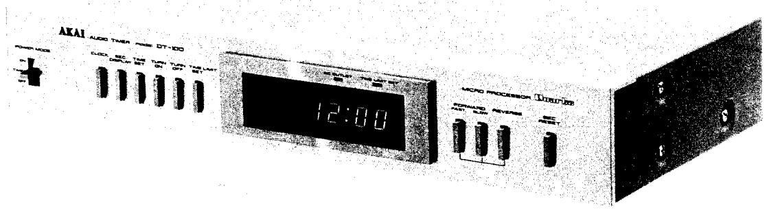
II. CONTROLS
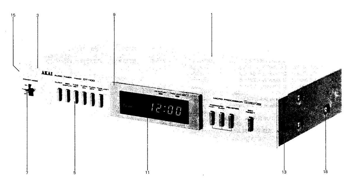
1. MODEL DT-100

Fig. 1 Controls
- 1. POWER MODE SELECTOR
- 2. CLOCK BUTTON
- 3. SEC. DISPLAY BUTTON
- 4. TIME SET BUTTON
- 5. TURN ON BUTTON
- 6. TURN OFF BUTTON
- 7. TIME LIMIT SET BUTTON
- 8. DIMMER SENSOR (Auto)
- 9. TIME DISPLAY
- 10. AC OUTLET INDICATOR
- 11. TIME LIMIT SET INDICATOR
- 12. FAST AND SLOW BUTTONS
- 13. REVERSE BUTTON
- 14. SEC. RESET BUTTON
- 15. 12 HOUR/24 HOUR DISPLAY SELECTOR (Not on some models)
- 16. AC OUTLETS (Unswitched) (Not on some models)
- 17. AC POWER CORD
- 18. AC OUTLETS (Switched)
- 19. VOLTAGE SELECTOR (Not on some models)
- 20. AC INLET
2. MODEL DT-200

- 1. POWER MODE SELECTOR
- 2. FUNCTION SELECTOR KEYS
- 3. PROGRAM MEMORY SELECTOR KEYS (1 to 4)
- 4. DAY SET KEY
- 5. DIMMER SENSOR (Auto)
- 6. DIGITAL FL DISPLAY
- 7. AC OUTLET INDICATOR
- 8. ONE HOUR PLAY INDICATOR
- 9. AM/PM PROGRAMING KEYS (Not on some models)
- 10. PROGRAMING KEYS
- 11. AM/PM INDICATORS (Not on some models)
- 12. ONE HOUR PLAY KEY
- 13. CLEAR KEY
- 14. TURN OFF KEY
- 15. TURN ON KEY
- 16. UNSWITCHED AC OUTLET (Not on some models)
- 17. SWITCHED AC OUTLETS
- 18. VOLTAGE SELECTOR (Not on some models)
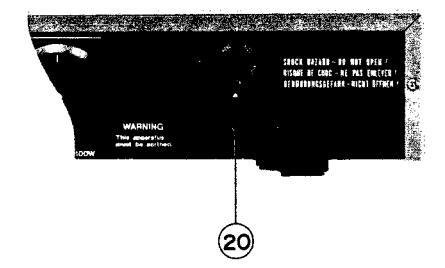
Fig. 2 Controls
- 19. 12 HOUR/24 HOUR DISPLAY SELECTOR (Not on some models)
- 20. AC POWER CORD (Some models are equipped with an AC Inlet instead of an AC cord. Connect with an appropriate power cord.)
- 21. AC OUTLETS (Switched)
1. MODEL DT-100
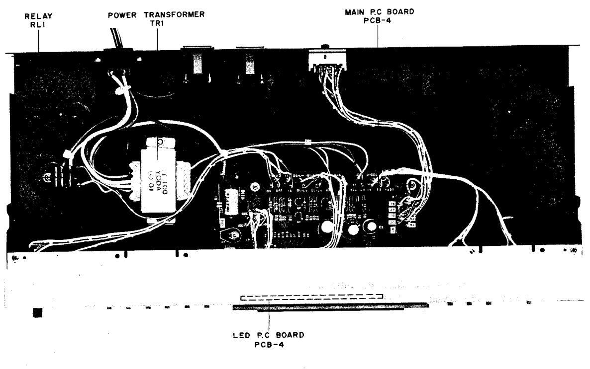
Fig. 3 Top VIEW
2. MODEL DT-200
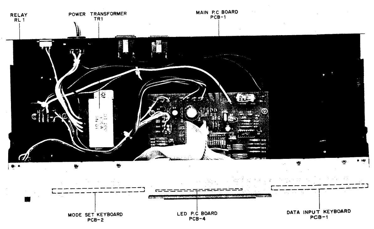
Fig. 4 Top View
MODEL DT-100
1. SET THE TIMER TO THE ACTUAL TIME
- 1) Plug in the Power Cord to a household AC Outlet.
- 2) On the Time Display "AM 12:00" or "0:00" will flash on and off depending on the setting of 12 Hour/24 Hour Display selector.
- Press the Time Set button, then keep pressing the Fast or Slow button until the actual time appears on the Time Display.
- Press the Sec Display button, then the Sec Reset button to set the seconds to zero (to synchronize the Timer with the actual time).
- 5) Press the Clock button so that even if the Fast or Slow button is pressed accidentally the actual time that was set will not change.
2. SET THE TIMER
- 1) Connect the external components' power cords to the Timer's AC Outlets (switched).
- Plug in the Power Cord to a household AC Outlet and set the Timer to the actual time. (See "SET THE TIMER TO THE ACTUAL TIME".)
- Set the Power Mode Switch to ON and adjust the external components (following the manufacturers' instructions).
- Press the Turn ON button, the Fast or Slow button and set the time for the external components to turn on.
- 5) Press the Turn Off button, the Fast or Slow button and set the time for the external components to turn off.
- 6) Press the Clock button.
- 7) Set the Power Mode selector to Timer.
- When starting the timer from OFF, please put the Power Mode Switch to OFF and then TIMER.
3. SET THE TIME LIMIT
- 1) Connect the external components to the Timer's AC Outlets.
- 2) Plug in the Power Cord to a household AC Outlet and set the Timer to the actual time.
- Set the Power Mode Switch to ON and adjust the external components (follow the manufacturers' instructions).
- 4) Press the Time Limit Set Button, the Fast or Slow Button and set the length of time the external components are to be on (in other words after how long the external components are to be turned off).
- 5) Press the Clock Time Button.
- 6) Set the Power Mode Switch to TIMER
- To cancel the Timer Limit Set, set the time length to "0:00".
- Time Limit will take priority over the time set to turn off.
If you have made a mistake in any of the above ("SET THE TIMER TO THE ACTUAL TIME", "SET THE TIMER", "SET THE TIME LIMIT") repeat the whole procedure.
4. BLACKING
After a blackout, the Time Display will revert to flashing "AM 12:00" or "0:00". Therefore reset the Timer after a blackout.
To reconfirm the times set press the following buttons: Time for the external components
to turn on ...... Turn On Button Time for the external components
to turn off ..................................
MODEL DT-200
1. SETTING THE TIMER TO THE ACTUAL TIME
Taking setting to 7:00 a.m. Sunday as an example:
-
Connect the timer's power cord to the mains power supply.
- The 'E' error mark on the FL Display should flash. • The 'E' will also flash repeatedly after power failures.
- 2) Depress the TIME SET key. Items still to be set will begin to flash on the FL Display. Depress the PROGRAMING keys in the following order:
1. 24 Hour Indication
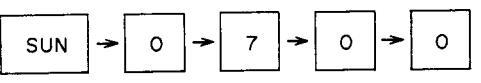
If it is for 7 o'clock in the evening, set as 19:00.


-
Keeping exactly the same, wait until the 7 a.m. announcement of the time, standard time, etc. When it is 7 a.m. depress the SEC RESET key.
- NOTE: The minute indication will not change when the SEC RESET key is depressed during the period 0 to 29 secs. One minute will be added during the period 30 to 59 secs.
-
4) Depress the CLOCK key.
- The flashing concentric circles will disappear.
Your timer is now set but if you made a mistake in setting the timer, repeat from Step 2.
2. ONE HOUR PLAY
Overrides all other operations. Please set the timer to CLOCK always.
- 1) The POWER MODE selector must be set to TIMER.
- 2) Depress the ONE HOUR PLAY key. Cancel by depressing the CLOCK key.
3. PROGRAMING
This timer can be programed to turn the power on four times and the power off four times.
There follows four examples of programs which can be retained in the timer's memory.
PROGRAM 1
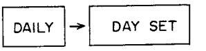
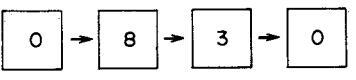
Turn on at 7:00 a.m. and off at 8:00 a.m. daily.
PROGRAM 2
Turn on at 9:00 a.m. and turn off at 9:45 a.m. on Mondays, Wednesdays and Fridays.
PROGRAM 3
Turn on at 7:30 p.m. (19:30) and turn off at 8:30 p.m. (20:30) on Tuesdays, Thursdays and Saturdays.
PROGRAM 4
Turn on at 9:00 p.m. (21:00) on Sundays and turn off at 11:30 a.m. the following morning.
• Confirm program setting by depressing the PROGRAM SET key and the respective PROGRAM MEMORY selector key. The turn on time will be shown. Depress the TURN OFF key to show the turn off time.
4. PROGRAM 1
- 1) Depress the PROGRAM SET key.
- 2) Depress the PROGRAM MEMORY selector key 1.
- 3) Depress the TURN ON key.
- Use the PROGRAMING key to set the day when the power is to turn on.
-
5) Set the timer to the time when the timer is to turn on.With the 12 hour indication depress the AM key
- first.

- 6) Depress the TURN OFF key.
-
7) Depress the PROGRAMING keys in the following order:
- With the 12 hour indication, depress the AM key first.

5. PROGRAM 2
- 1) Depress the PROGRAM SET key.
- 2) Depress PROGRAM MEMORY selector key 2.
- 3) Depress the TURN ON key.
- 4) Use the PROGRAMING keys to set the day when the power is to turn on.

- Depress the respective day key once and it appears, twice and it is cancelled.
-
5) Set the timer to the time when it is to turn on.
- With the 12 hour indication, depress the AM key first.

6) Depress the TURN OFF key.
• With the 12 hour indication, depress the AM key first.

6. PROGRAM 3
- 1) Depress the PROGRAM SET key.
- 2) Depress PROGRAM MEMORY selector key 3.
- 3) Depress the TURN ON key.
-
4) Use the PROGRAMING keys to set the days when the power is to turn on.
- Depress the respective day key once and it appears, twice and it is cancelled.

5) Set the timer to the time when it is to turn on.With the 12 hour indication, depress the PM key first.


- 6) Depress the TURN OFF key.
- 7) Depress the PROGRAMING keys in the following order.
• With the 12 hour indication, depress the PM key first.
24 Hour Indication

12 Hour Indication
7. PROGRAM 4
- 1) Depress the PROGRAM SET key.
- 2) Depress the PROGRAM MEMORY selector key 4.
- 3) Depress the TURN ON key.
- Use the PROGRAMING keys to set the day when the power is to turn on.

- Depress the respective day key and it appears, twice and it is cancelled.
-
5) Set the timer to the time when it is to turn on
- With the 12 hour indication, depress the PM key first.
24 Hour Indication

12 Hour Indication

- 6) Depress the TURN OFF key.
-
7) Depress the PROGRAMING keys in the following order:
- With the 12 hour indication, depress the AM key first.

- If you have made a mistake in setting any program:
- 1) Depress the PROGRAM SET key.
- 2) Depress the PROGRAM MEMORY selector for the mistaken program.
- 3) Depress the CLEAR key.
- 4) Re-program.

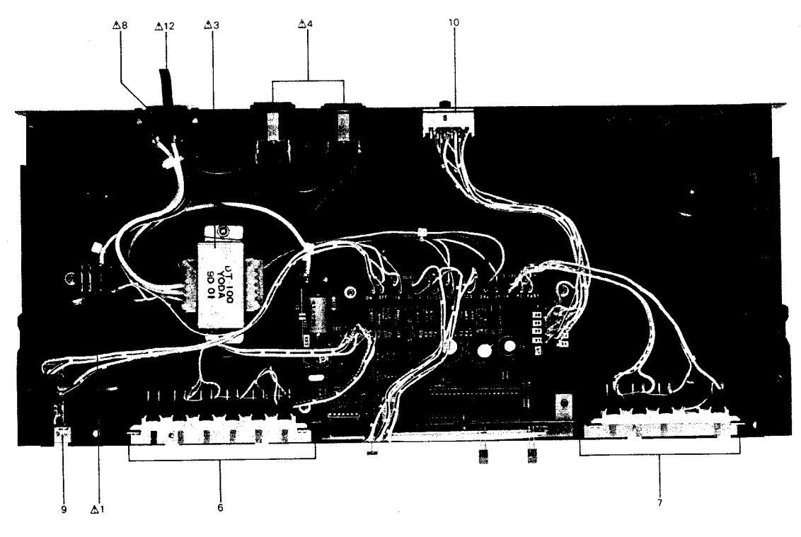
Fig. 5 Main P.C Board PCB-4 (DT-100)

Fig. 6 Main P.C Board PCB-1-2 (DT-200)
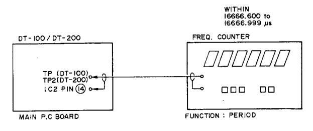
Fig. 7 Instrument Connections
REFERENCE PERIOD SIGNAL MICROADJUST-MENT (Refer to Fig. 5 to 7.) Connect the frequency counter to TP (DT-100), TP2 (DT-200) and pin (1) of IC2, set function to "period".
Adjust the trimmer capacitor C4 so that frequency counter reads within 16666.600 to 16666.699 µs.
Quick confirmation of the timer setting is possible by shortcircuiting TP1s (DT-200 only), as this will cause the set's time count to become 60 times as large, changing the digit that would otherwise be for "minutes" into "seconds", and that for "hours" into "minutes".
NOTE: Disconnect the power cord before short (or release). TP1s.
VI. COMPOSITION OF VARIOUS P.C BOARDS
1. MAIN P.C BOARD PCB-4 (DT-100)

2. MAIN P.C BOARD PCB-1-2 (DT-200)

3. LED P.C BOARD PCB-4 (DT-100/DT-200)

15
SECTION 2
PARTS LIST
TABLE OF CONTENTS
| I. | MODEL DT-100 | ||
|---|---|---|---|
| 1. MAIN P.C BOARD (PCB-4) BLOCK | 22 | ||
| 2. LED P.C BOARD (PCB-4) BLOCK | 22 | ||
|
22
23 |
||
| 11. | MODEL DT-200 | ||
| 1. MAIN P.C BOARD (PCB-1-2) BLOCK | ••••• | 24 | |
| 2. LED P.C BOARD (PCB-4) BLOCK | 24 | ||
| 3. ASSEMBLY BLOCK | 24 | ||
| 4. FINAL ASSEMBLY BLOCK | • | 25 | |
| INDI | EX | 26 | |
| A. S. 1977 |
Resistor and Capacitor which is not listed in this parts list, please refer to COMMON LIST FOR SERVICE PARTS.
HOW TO USE THIS PARTS LIST
- 1. This parts list is compiled by various individual blocks based on assembly process.
- 2. When ordering parts, please describe parts number, serial number, and model number in detail. 3. How to read list.
Ref. No. Parts No.
12 - 115
The reference number corresponds with illustration or photo number of that particular parts list.
-This number corresponds with the Figure Number.
-This number corresponds with the individual parts index number in that figure.
-A small "x" indicates the inability to show that particular part in the Photo or Illustration.
-Schematic Diagram Number of individual manufactured part.
(not required for parts order)
ELVWHEEL BLOCK #13
| 2-115x | 800425 | Flywheel Block Assy. Comp. | RDG #13 |
|---|---|---|---|
| 2-116 | 244506 | Flywheel Only | RD-233 |
| 2-117x | 244754 | Felt, Flywheel | RD 275 |
| 2-118 | 251324 | Main Metal Case | RD-236 |
| 2-119 | 253080 | Main Metal | RD-237 |
Description
- 4. The symbol numbers shown on the P.C. Board list can be matched with the Composite Views of components of the Schematic Diagram or Service Manual.
- 5. The indications of Resistors and Capacitors in the photos of P.C. Board are being eliminated.
- 6. The shape of the parts and parts name, etc. can be confirmed by comparing them with the parts
- shown on the Electrical Parts Table of P.C. Board.
-
7. Both the kind of part and installation position can be determined by the Parts Number. To determine where a parts number is listed, utilize Parts Index at end of Parts List.
- It is necessary first of all to find the Parts Number. This can be accomplished by using the Reference Number listed at right of parts number in the Parts Index. (meaning of ref. no. outlined in Item 3 above).
- 8. Utilize separate "Price List for Parts" to determine unit price. The most simple method of finding parts Price is to utilize the reference number.
CAUTION:
20
- 1. When placing an order for parts, be sure to list the parts no. model no., and description. There are instances in which if any of this information is omitted, parts cannot be shipped or the wrong parts will be delivered.
- 2. Please be careful not to make a mistake in the parts no. If the parts no. is in error, a part different from the one ordered may be delivered.
- 3. Because parts number and parts unit supply in the Preliminary Service Manual (Basic Parts List) may be partially changed, please use this parts list for all future reference.
△ INDICATES SAFETY CRITICAL COMPONENTS. FOR CONTINUED SAFETY, REPLACE WARNING: SAFETY CRITICAL COMPONENTS ONLY WITH MANUFACTURER'S RECOMEMNDED PARTS.
AVERTISSEMENT: A IL INDIQU LES COMPOSANTS CRITIQUES DE SURETE. POUR MAINTENIR LE DEGRE DE SECURITE DE L'APPAREIL NE REMPLACER LES COMPOSANTS DONT LE FONCTIONNEMENT EST CRITIQUE POUR LA SECURITE QUE PAR DES PIECES RECOM-MANDEES PAR LE FABRICANT.
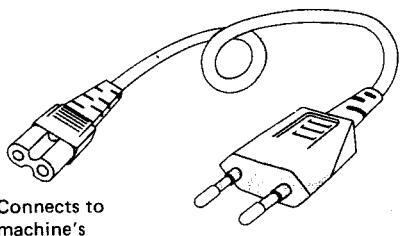
AC INLET SYSTEM
This model is equipped with an AC INLET SYSTEM. Please refer to the AC INLET SYSTEM CHART below for the specific type. By the AC INLET SYSTEM, AC (mains) cord can be connected to and disconnected from the model because the model is provided with socket exclusively for AC (mains) cord on its main body.
Please note, however, that certain models are not equipped with this system and has a built-in AC (mains) cord as before.
AC INLET SYSTEM CHART
CLASS I
Most of European countries
Australia
differs according
to wall socket


Picture 2 AC (mains)
CLASS II
This mark indicating double insulation will be attached to machine's rear parrel
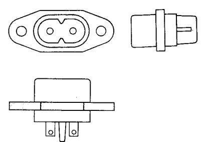
machine's AC Inlet
Most of the European countries

differs according to wall socket

| Stan | dard | Description | Type of AC Inlet | Parts No. |
|---|---|---|---|---|
| CEE | Cord Set CEE (3 cores) | 3P | EW302993 | |
| BEAB | Cord Set BEAB (3 cores) | 3P | EW302994 | |
| Class 1 | SAA | Cord Set SAA (3 cores) | 3P | EW302996 |
| U/T | Cord Set U/T (3 cores) | 3P | EW302646 | |
| Class II | CEE | Cord Set CEE (2 cores) | 2P | EW638144 |
| BEAB | Cord Set BEAB (2 cores) | 2P | EW302995 | |
| SAA | Cord Set SAA (2 cores) | 2P | EW302991 | |
| U/T | Cord Set U/T (2 cores) | 2P | EW302899 |
I. MODEL DT-100
1. MAIN P.C BOARD (PCB-4) BLOCK
|
Ref.
No. |
Parts No. | Description |
Schematic
No. |
|---|---|---|---|
| 1-IC1 | EI700654 | IC MN6076 | MN6076 |
| 1-IC2 | EI700655 | IC MSM5562 | MSM5562 |
| 1-01T03 | ET328569 | TR 2SC2320 (F) | 45-1-409 |
| 1-04 | ET700657 | TR 2SA999 (F), (G) | 2SA999F, G |
| 1-D1.2 | ED700722 | D Silicon H SR1K-2 | SR1K-2 |
| 1-D3T09 | ED302379 | D Silicon H 1SS53 | 45-3-43 |
| 1-D10 | ED700658 | D Zener H MZ320 A | MZ320A |
| 1-D11 | ED700659 | D Zener H MZ412 B | HZ412B |
| 1-D12 | ED700723 | D Zener H MZ306 B | MZ306B |
| I-X'TAL | E1700662 | OSC X'tal 3.932160MC | 3.932160MHZ |
| 1-FLD | EI700656 | IND FLD 5-LT-02 Character | 5-LT-02 |
| 1-C1 | EC306477 | ▲ C Oil H ECN-C 103M 450AC | |
| (U/T) | 24-8-6 | ||
| 1-C1 | EC325671 | A C MP V 103M 250AC (CEE) | 24-9-134 |
| 1-C4 | EC315346 | C S-Fix H ECV-1ZW50X32E | |
| 5.0-55 | 24-2-48 |
2. LED P.C BOARD (PCB-4) BLOCK
|
Ref.
No. |
Parts No. | Description |
Schematic
No. |
|---|---|---|---|
| 2-D13 | ED700664 |
LED LN-224RP Red
(AC OUTLET) |
LN-224RP |
| 2-D14 | ED700665 |
LED LN-324GP Grn
(TIME LIMIT SET) |
LN-324GP |
| 2-CDS | ET700663 | CDS P380-14 (AUTO DIMMER) | P380-14 |
3. ASSEMBLY BLOCK
ASSEMBLY BLOCK
|
Ref.
No. |
Parts No. | Description |
Schematic
No. |
No. | Parts No. | Description | No. |
|---|---|---|---|---|---|---|---|
|
3-1
3-2x 3-3 3-4 3-5x |
EP700724
EP700725 BT700666 EJ700667 EJ700668 |
|
LY1F-US5
LY2F-VD DT-100CEE S2-723B-50 TYPE-418038 |
3-9
3-10 3-11x 3-12 3-13x |
ES700676
ES700677 EZ631945 EW374894 EJ296853 |
SW Lever SJE-23P
SW Slide SW42-7P (U/T) Strain Relief SR-4N-4 (U/T) ▲ AC Cord 2 Cores VM-0129A J (U/T) ▲ Socket Inlet CM-3 |
SJE-23P
SQ-42-7P 2-7-49 26-3-19 |
|
3-6
3-7 3-8 |
ES700674
ES700675 ES700720 |
SW Push SUH-62V 6-THROW
SW Push SUH-42V 4-THROW |
SUH-62V
SUH-42V ESE-372 |
3-14x | EW496855 |
UCEB 3P (CEE)
AC Cord 3 Cores VM-0099 E (CEE) |
31-1-199
26-3-27 |
4. FINAL ASSEMBLY BLOCK
FINAL ASSEMBLY BLOCK
|
Ref.
No. |
Parts No. | Description |
s⊂ hematic
No. |
|---|---|---|---|
| 4-1 | SP700669 | Case | 015B11-S |
| 4-2x | SP700670 | Case (BL) | 01SB11-B |
| 4-3 | SP700671 | Panel Front | 0iSB03-S |
| 4-4x | SP700673 | Panel Front (BL) | 01 SB 03-B |
| 4-5 | SK700678 | Key Top 1 | 015B09-S |
| 4-6x | SK700679 | Key Top 1 (BL) | 0|SB09-B |
| 4-7 | SK700680 | Key Top 2 | 0|SB10-S |
| 4-8x | SK700681 | Key Top 2 (BL) | 0|SB10-B |
| 4-9 | SP700682 | Panel Sub | 01 SB04100S |
| 4-10x | SP700684 | Panel Sub (BL) | 0|SB04100B |
| 4-11 | SZ700685 | Panel Smoke | 0 SB05-CEE |
| 4-12x | SZ323193 | FLD Plate | AT V-4037 |
| 4-13 | TA322176 | Pad (L-1) | AT K-2015 |
| 4-14x | TA322178 | Pad (L-1-BL) | AT K-2015 |
| 4-15 | TA322179 | Pad (R-1) | AT K-2015 |
| 4-16x | TA322180 | Pad (R-1-BL) | AT K-2015 |
| 4-17x | SA311742 | Round Foot | PC-2032 |
| 4-18 | ZS321782 | BID 40 × 08 STL N 13 | |
| 4-19x | ZS537074 | BID 40 × 06 STL BNI | |
| 4-20x | ZS609478 | PAN 26 × 06 STL BNI | |
| 4-21x | ZS417407 | PAN 30 × 10 STL BNI | |
| 4-22x | ZS609208 | T2 PAN 30 × 08 STL BNI |
When ordering parts, please quote Parts Number, Description and Model Number.
1. MAIN P.C BOARD (PCB-1-2) BLOCK 2. LED P.C BOARD (PCB-4) BLOCK
|
Ref.
No. |
Parts No. | Description |
Schematic
No. |
|---|---|---|---|
| 1-IC1 | EI700693 | IC MP1508S | MP-1508S |
| 1-IC2 | EI700655 | IC MSM5562 | MSM 5562 |
| 1-Q1 | ET537300 | TR 2SD361 (D) (E) | 45-1-143 |
| 1-Q2 | ET700657 | TR 2SA999 (F) (G) | 2SA999F, G |
| 1-Q3T07 | ET328569 | TR 2SC2320 (F) | 45-1-409 |
| 1-D1T013 | ED302379 | D Silicon H 1SS53 | 45-3-43 |
| 1-D14,15 | ED700722 | D Silicon H SR1K-2 | SR1K-2 |
| 1-D21 | ED700695 | D Zener H MZ333 A | MZ333A |
| 1-D22 | ED700696 | D Zener H MZ416 B | MZ416B |
| 1-D23 | ED700721 | D Zener H MZ305 B | MZ305B |
| 1-D24 | ED700723 | D Zener H MZ306 B | MZ306B |
| 1-X'TAL | E1700662 | OSC X'tal 3.932160MC | 3.932160MH2 |
| 1- FL D | EM700698 | IND FLD 6-LT-43 | 6-LT-43 |
| 1-C8 | EC315346 | C S-Fix H ECV-1ZW50X32E | |
| 5.0-55 | 24-2-48 | ||
| 1-C10 | EC306477 | 🛆 C Oil H ECN-C 103M | |
| 450AC (U/T) | 24-8-6 | ||
| 1-C10 | EC325671 | ▲ C MP V 103M 250AC (CEE) | 24-9-134 |
|
Ref.
No. |
Parts No. | Description |
Schematic
No. |
|---|---|---|---|
| 2-D31 | ED700665 | LED LN-324GP GRN (AM) | LN-324GP |
| 2-D32 | ED700665 | LED LN-324GP GRN (PM) | LN-324GP |
| 2-D33 | ED700664 | LED LN-224RR RED | |
| (AC OUTLET) | LN-224RP | ||
| 2-D34 | ED700665 | LED LN-324GP GRN | |
| (ONE HOUR PLAY) | LN-324GP | ||
| 2-CDS | ET700663 | CDS P380-14 (DIMMER) | P380-14 |
3. ASSEMBLY BLOCK

ASSEMBLY BLOCK
|
Ref.
No. |
Parts No. | Description |
Schematic
No. |
Ref.
No. |
Parts No. | Description |
Schematic
No. |
|---|---|---|---|---|---|---|---|
|
3-1
3-2x 3-3 3-4 |
EP700724
EP700725 BT700697 EJ700667 EJ700668 |
|
LY1F-US5
LY2F-VD DT-200CEE S2-723B-50 |
3-11x
3-12 3-13 3-14 |
ES700711
ES700720 ES700676 ES700707 |
SW Operation (BL)
01SB07-B (CEE) |
01SB07-B
ESE-372 SJE-23P SA-1 |
| J-JX | 23700000 | Type-418038 (CEE) | TYPE-418038 | 3-15x | EZ700744 | Strain Relief F4 (U/T) | |
|
3-6
3-7x |
ES700708
ES700709 |
SW Operation 01SB06-S
SW Operation (BL) 01SB06-B |
01SB06-S
01SB06-B |
3-16 | EW374894 |
AC Cord 2 Cores
VM-0129A J (U/T) |
26-3-19 |
| 3-8 | ES700712 | SW Operation 01SB08-S (U/T) | 01SB08-S | 3-17x | EJ296853 |
▲ Socket Inlet CM-3
UCEB 3P (CEE) |
31-1-199 |
| 3-9x | E5/00/15 | 01SB08-B (U/T) | 01SB08B | 3-18x | EW496855 |
AC Cord 3 Cores
VM-0099 E (CEE) |
26-3-27 |
| 3-10x | ES700710 | SW Operation UISB07-S (CEE) | 01SB07-S | 1 |
4. FINAL ASSEMBLY BLOCK

FINAL ASSEMBLY BLOCK
|
Ref.
No. |
Parts No. | . Description |
Schematic
No. |
|
|---|---|---|---|---|
| 4-1 | SP700669 | Case | 01SB11-S | |
| 4-2x | SP700670 | Case (BL) | 01SB11-B | |
| 4-3 | SP700701 | Panel Front (U/T) | 015B02-S | |
| 4-4x | SP700702 | Panel Front (BL) (U/T) | 015B02-B | |
| 4-5x | SP700699 | Panel Front (CEE) | 015B01-S | |
| 4-6x | SP700700 | Panel Front (BL) (CEE) | 015B01-B | |
| 4-7 | SP700703 | Panel Sub | 015 B04200S | |
| 4-8x | SP700704 | Panel Sub (BL) | 015 B04200B | |
| 4-9 | SK700680 | Key Top 2 | 01SB10-S | |
| 4-10x | SK700681 | Key Top 2 (BL) | 015B10-B | |
| 4-11 | TA322179 | Pad (R-1) | ATK-2015 | |
| 4-12x | TA322180 | Pad (R-1-BL) | ATK-2015 | |
| 4-13 | TA322176 | Pad (L-1) | ATK-2015 | |
| 4-14x | TA322178 | Pad (L-1-BL) | ATK-2015 | |
| 4-15 | SZ700706 | Panel Smoke (U/T) | 015B05-U/T | |
| 4-16x | SZ700685 | Panel Smoke (CEE) | 01SB05-CEE | |
| 4-17 | Z$321782 | BID 40 × 08 STL N13 | ||
| 4-18x | ZS537074 | BID 40 × 06 STL BNI (BL) | ||
| 4-19x | SA311742 | Round Foot | PC-2032 | |
| 4-20x | ZS609478 | PAN 26 × 06 STL BNI | ||
| 4-21x | ZS417407 | PAN 30 × 10 STL BNI | ||
| 4-22x | ZS609208 | T2 PAN 30 × 08 STL BNI | ||
| 4-23x | SZ323193 | FLD Plate | AT V-4037 | |
- When ordering parts, please quote Parts Number, Description and Model Number.
INDEX
1. MODEL DT-100
2. MODEL DT-200
| Parts No. |
Ref. No. &
Symbol No. |
Parts No. |
Ref. No. &
Symbol No. |
Parts No. |
Ref. No. &
Symbol No. |
Parts No. |
Ref. No. &
Symbol No. |
|---|---|---|---|---|---|---|---|
|
BT700666
EC306477 EC315346 EC325671 ED302379 ED700658 ED700659 ED700664 ED700665 ED700722 |
3-3
1-C1 1-C4 1-C1 1-D3T09 1-D10 1-D11 2-D13 2-D14 1-D1,2 |
BT700697
EC306477 EC315346 EC325671 ED302379 ED700664 ED700665 ED700665 ED700665 ED700695 |
3-3
1-C10 1-C8 1-C10 1-D1T013 2-D33 2-D31 2-D32 2-D34 1-D21 |
||||
|
ED700723
EI700655 EI700656 EI700654 EJ700662 EJ296853 EJ700668 EP700724 EP700725 |
1-D12
1-IC2 1-FLD 1-IC1 1-X'TAL 3-13x 3-4 3-5x 3-1 3-2x |
ED700696
ED700721 ED700722 ED700723 E1700655 E1700662 E1700693 EJ296853 EJ700667 EJ700668 |
1-D22
1-D23 1-D14,15 1-D24 1-IC2 1-X'TAL 1-IC1 3-17x 3-4 3-5x |
||||
|
ES700674
ES700675 ES700676 ES700720 ET328569 ET700657 ET700653 EW374894 EW496855 |
3-6
3-7 3-9 3-10 3-8 1-Q1T03 1-Q4 2-CDS 3-12 3-14x |
EM700698
EP700724 EP700725 ES700676 ES700707 ES700708 ES700709 ES700710 ES700711 |
1-FLD
3-1 3-2x 3-13 3-14 3-6 3-7x 3-10x 3-11x 3-8 |
||||
|
EZ 631945
SA 311742 SK 700678 SK 700679 SK 700680 SK 700681 SP 700670 SP 700670 SP 700671 SP 700673 |
3-11x
4-17x 4-5 4-6x 4-7 4-8x 4-1 4-2x 4-3 4-4x |
ES700713
ES700720 ET328569 ET537300 ET700657 ET700663 EW374894 EW496855 EZ700744 SA311742 |
3-9x
3-12 1-Q3T07 1-Q1 1-Q2 2-CDS 3-16 3-18x 3-15x 4-19x |
||||
|
SP700682
SP700684 SZ323193 SZ700685 TA322176 TA322178 TA322179 TA322180 ZS321782 ZS417407 |
4-9
4-10x 4-12x 4-11 4-13 4-14x 4-15 4-16x 4-18 4-21x |
SK 700680
SK 700681 SP700669 SP700670 SP700700 SP700700 SP700701 SP700702 SP700703 SP700704 |
4-9
4-10x 4-1 4-2x 4-5x 4-6x 4-3 4-4x 4-7 4-8x |
||||
|
ZS 537074
ZS 609208 ZS 609478 |
4-19x
4-22x 4-20x |
SZ323193
SZ700685 SZ700706 TA322176 TA322178 TA322179 TA322180 ZS321782 ZS417407 ZS537074 |
4-23x
4-16x 4-15 4-13 4-14x 4-11 4-12x 4-17 4-21x 4-18x |
||||
|
ZS609208
ZS609478 |
4-22x
4-20x |
||||||
| , | |||||||
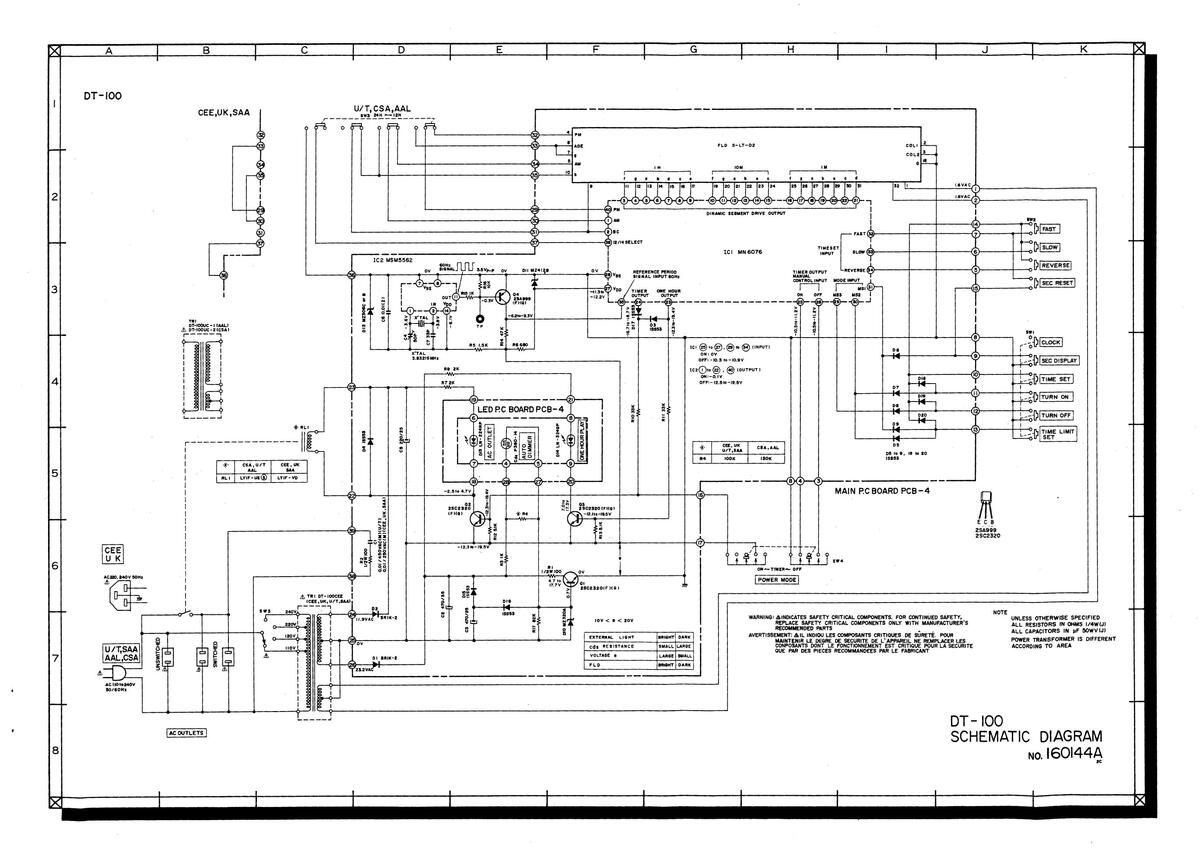
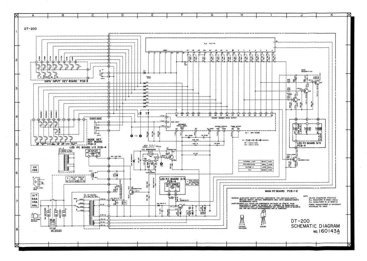
SECTION 3
SCHEMATIC DIAGRAM
1. DT-100 NO. 160144A SCHEMATIC DIAGRAM 2. DT-200 NO. 160143A SCHEMATIC DIAGRAM


 Loading...