

HARD DISK RECORDER
Version 3.11 Addendum
Operator’ s Manual
WARNING
To prevent fire or shock hazard, do not
expose this appliance to rain or moisture.
000306 Printed in Japan

IMPORTANT NOTICE
The material in this document is copyright to AKAI professional M.I. Corp., and may not be
quoted or reproduced in any form without written permission from the company.
LIMITED SOFTWARE WARRANTY POLICY
All the software provided with, or purchased especially for, AKAI products has been tested for
functionality . AKAI professional M.I. Corp. will make its best ef forts to correct reported software
defects for future releases subject to technical practicabilities. AKAI professional M.I. Corp.
makes no warranty or representation either expressed or implied with respect to the system’s
performance or fitness for a particular purpose.
In no event will AKAI professional M.I. Corp. be liable for direct or indirect damages arising
from any defect in the software or its documentation. Further, AKAI professional M.I. Corp. will
not accept any liability for any programs, sounds, audio recording or sequences stored in or
used with AKAI products, including the cost of recovery of such data.
The warranties, remedies and disclaimers above are exclusive and take prec-edence over all
others, oral or written, express or implied, to the extent permitted by law in the geographical
area of the product’s use. No employee of AKAI professional M.I. Corp., agent, distributor or
employee of an agent or distributor is authorised to offer any variation from this policy.
Trademarks:
All trademark, product and company names are the property of their respective owners.

Version 3.11 Addendum
TABLE OF CONTENTS
SUMMARY OF NEW FEATURES.....................................................................................2
MULTI-MACHINE SYNCHRONISATION..........................................................................2
MULTI-MACHINE CONNECTIONS.........................................................................3
Akainet (Ethernet) Connections.....................................................................3
Sync Connections..........................................................................................4
MULTI-MACHINE SETUP.......................................................................................7
Set Machine IDs............................................................................................7
Master/Slave Selection..................................................................................8
Save Settings To Flash..................................................................................9
MULTI-MACHINE OPERATION............................................................................10
Parameter settings......................................................................................10
Using Digital Audio Interfaces......................................................................11
Error Messages...........................................................................................13
LOADING OPERATING SYSTEMS FROM DISK...........................................................14
TDIF OPTION BOARD (IB-D8TIF)..................................................................................16
OTHER CHANGES.........................................................................................................17
Page 1

Version 3.11 Addendum
SUMMARY OF NEW FEATURES
Version 3.11 software for the Akai DR16pro includes the following new features and
improvements:
• Addition of multi-machine synchronisation system that allows multiple DR16pro
transports to be accurately locked together, even while jogging.
• Ability to load new operating systems from Mac HFS format CD-ROM disks.
• Support for IB-D8TIF, 8-channel TDIF digital audio option board.
• Other bug fixes and improvements.
Please refer to the rest of this document for further information and for details of changes.
MULTI-MACHINE SYNCHRONISATION
The new multi-machine synchronisation function allows multiple DR16pro machines to be
accurately synchronised for playback and recording. The system uses a combination of the
AKAINET connections on each machine (to pass synchronisation messages from one
machine to another) and the SYNC IN/OUT connections on each machine (to synchronise
the sample clocks of each machine in the system).
When configured for multi-machine synchronisation, the SLAVE machines will remain locked
to the MASTER machine and will follow any transport commands given to the MASTER
machine (including playback and record as well as locate functions).
With the addition of an Akai RE32 Multitrack Remote Controller, the system will behave as
if there is a single ‘multitrack’ project encompassing all the tracks allowing editing, transport
control and record functions across the entire system.
Page 2

Version 3.11 Addendum
MULTI-MACHINE CONNECTIONS
On the rear panel, you will find two BNC connectors, each with a terminator switch:
The AKAINET and SYNC IN/OUT connectors must both be connected as described in the
following sections to enable the multi-machine synchronisation function to be used.
Akainet (Ethernet) Connections
The AKAINET connectors on each DR16pro should be connected together to allow multimachine synchronisation messages to be passed from one machine to another. This should
be done using standard Ethernet BNC cables. These are chained between the AKNET BNC
connectors on each DR16pro using BNC ‘T’ connectors to link each cable where necessary.
If you are using an RE32 Remote Controller, this should also be connected to the AKAINET
bus as described in the RE32 manual.
Page 3
Version 3.11 Addendum
It is essential that the AKAINET TERMINATOR switch is switched to the ON position on
the first and last units in the chain. Failure to do so will prevent correct communications
and the system will not work correctly.
NOTE: The AKNET interface used in the Akai DR16pro system is 10-Base-2
Ethernet. There are certain rules that must be adhered to when setting up the system
to ensure reliable operation:
• All cables should be 50 ohm impedance.
• There should be a maximum of 185m of cable in the system between the first and
last nodes.
• There should be at least 0.5m of cable between each connection.
Sync Connections
The SYNC IN/OUT connectors on each DR16pro should be connected together to allow the
internal sample clocks of each machine in the system to be synchronised. This should be
done using standard video BNC cables. These are chained between the SYNC IN/OUT
BNC connectors on each DR16pro using BNC ‘T’ connectors to link each cable where
necessary.
It is essential that the SYNC IN/OUT TERMINATOR switch is switched to the ON position
on the first and last units in the chain. Failure to do so will prevent the system from
synchronising correctly.
Page 4

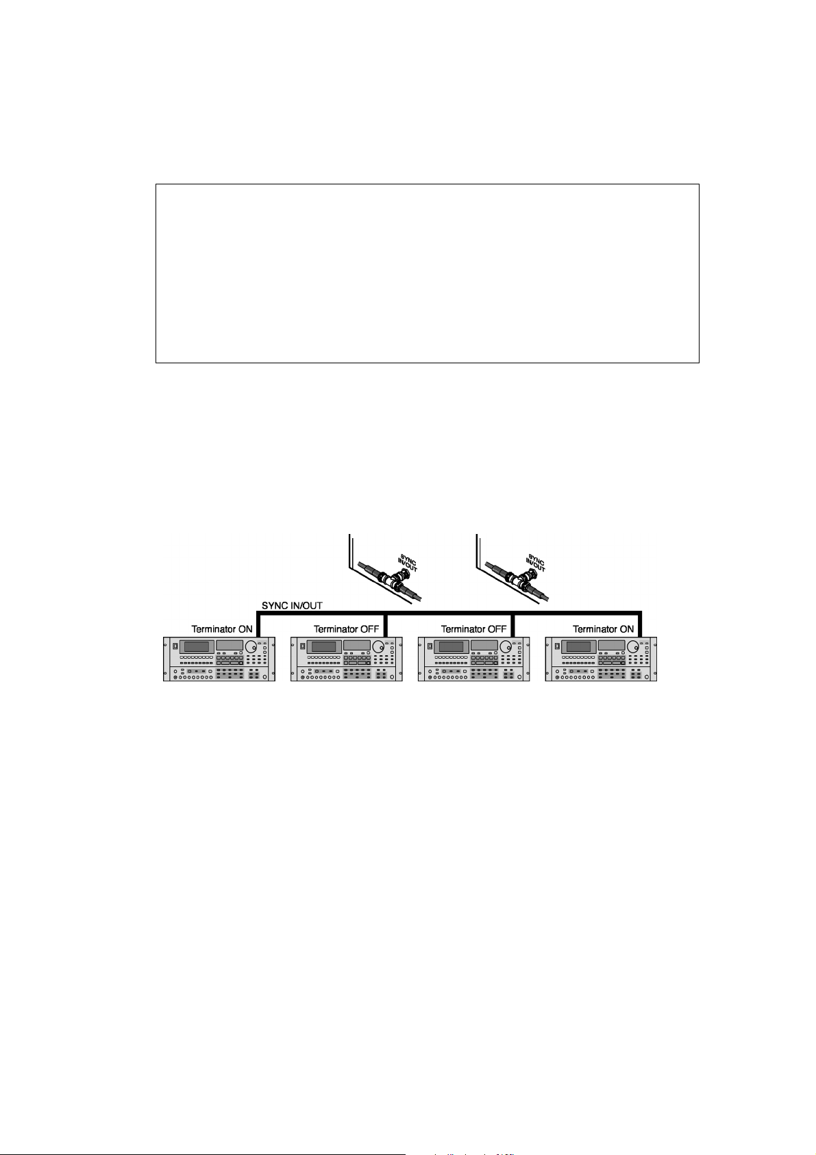
Version 3.11 Addendum
A synchronised multi-machine system comprising 4 machines would therefore be connected
as follows:
The AKAINET chain provides the necessary transport control, etc., whilst the SYNC IN/
OUT connection maintains accurate sample lock between all machines.
Page 5

Version 3.11 Addendum
However, bearing in mind that termination for the AKAINET connection must be switched
ON on the first and last machines in the chain, if the system shown above is being used
with the RE32 remote controller, the system would be configured as follows:
Because the RE32 is now the first machine in the chain, it should have termination switched
on. Of course, you may have more or less machines in your system - however many you
have, remember that termination must be switched ON on the first and last machines for the
system to work correctly.
NOTE: Due to the use of the SYNC IN/OUT connector to distribute the special
synchronisation clock signal fthroughout the multi-machine system, it is not currently
possible to use the system with Video Sync or Wordclock whilst using the multi-machine
synchronisation feature.
Page 6

Version 3.11 Addendum
MULTI-MACHINE SETUP
Step 1: Set Machine IDs
In multi-machine systems, each DR16pro must be assigned a unique Machine ID number
sequentially from 1 to the number of machines in the system.
The following procedure should be repeated on each DR16pro in the system:
1) Press the SUB-MENU key.
The key will flash and the display will show
2) Press the 3 (SETUP) key on the numeric keypad.
3) Use the JOG/SHUTTLE control to select the AKAINET menu.
You will see a display similar to the following:
4) Press the STORE/ENT key.
A message such as
selected Machine ID number.
5) Use the JOG/SHUTTLE control to change the ID number.
The range is 1 to 16.
6) Press the STORE/ENT key.
The Machine ID will now be set to the new value and the current settings, including the
new Machine ID number will be saved to Flash ROM.
MACHINE 01
will appear on the display showing the currently
SUB-MENU
.
Page 7

Version 3.11 Addendum
Step 2: Master/Slave Selection
To enable multi-machine synchronisation, one machine in the system must be nominated
as the MASTER and all others as SLAVES. The MASTER machine will always be the machine
set as MACHINE ID 1 in the previous step.
The following procedure should be repeated on each DR16pro in the system:
1) Press the SUB-MENU key.
The key will flash and the display will show
2) Press the 3 (SETUP) key on the numeric keypad.
3) Use the JOG/SHUTTLE control to select the AKAINET menu.
You will see a display similar to the following:
SUB-MENU
.
4) Press the STORE/ENT key.
A message such as
selected Machine ID number.
5) Use the SHUTTLE control to move the cursor to the MACHINE field.
You will see a display similar to the following:
6) Use the JOG/SHUTTLE control to select the MULT menu.
You will see a display similar to the following:
7) Use the SHUTTLE control to move the cursor to the right-hand field.
8)
On the MASTER machine (MACHINE ID 1):
MACHINE 01
will appear on the display showing the currently
On MACHINE 1, use the JOG wheel to select
MULT MASTER
On the SLAVE machine(s):
On other machines (MACHINE 2, 3 etc...), use the JOG wheel to select
9) Press the STORE/ENT key.
Page 8
.
MULT SLAVE
.

Version 3.11 Addendum
Step 3: Save Settings to Flash
Once the parameter settings described in the previous steps have been made, it is
recommended to save the current system settings to the DR16pro’s Flash ROM. This will
ensure that the system powers up correctly on subsequent occasions with the correct multimachine synchronisation settings on each machine.
The following procedure should be repeated on each DR16pro in the system:
1) Press the SUB-MENU key.
2) Press the 3 (SETUP) key.
3) Use the JOG/SHUTTLE control to select the
You will see a display similar to the following:
4) Press the STORE/ENT key.
The message
5) Press the STORE/ENT key.
The message
system settings have been successfully saved to Flash ROM.
SURE?
DONE
will appear on the display.
will appear momentarily on the display indicating that the current
FLASH SAVEFLASH SAVE
FLASH SAVE
FLASH SAVEFLASH SAVE
menu.
Page 9

Version 3.11 Addendum
MULTI-MACHINE OPERATION
Parameter Settings
For correct multi-machine synchronisation it is important that certain other parameters on
each DR16pro are set correctly. These should be configured automatically when the machines
are designated as a MASTER or SLAVE (as described in the previous step), but you may
like to confirm that these settings are correct following changes in the system setup that
may affect these parameters.
(i) Sample Rate
The sample rates of each DR16pro used in multi-machine system must be the same to
allow correct synchronisation. Changes in the sample rate on the MASTER machine will
automatically be transmitted to SLAVE machines as well
To confirm the sample rate setting:
1) Press the SUB-MENU key.
2) Press the 2 (DIGI) key.
3) Use the JOG/SHUTTLE control to select the
4) Press the STORE/ENT key.
The current sample rate setting will be shown by a display such as this:
(ii) Sample Clock Source
When operating with multi-machine synchronisation, the SYNC IN/OUT connection on the
DR16pro is used to transmit a special signal from the MASTER machine which is used as a
sample clock source on the SLAVE machines. The selection of this source on the slave
machines is made automatically when the multi-machine synchronisation system is enabled.
SMPL RATESMPL RATE
SMPL RATE
SMPL RATESMPL RATE
menu.
To confirm the sample clock source setting on SLAVE machines:
1) Press the SUB-MENU key.
2) Press the 2 (DIGI) key.
3) Use the JOG/SHUTTLE control to select the
4) Press the STORE/ENT key.
The sample source should be set to MULTI on each SLAVE machine:
DIGI SYNCDIGI SYNC
DIGI SYNC
DIGI SYNCDIGI SYNC
menu.
On the MASTER machine, the clock source will usually be set to internal (XTAL), but may
also be set to clock the system from a digital audio source (DIGI or DINLR) when operating
the system using digital audio interfaces as described in the next section.
NOTE: Due to the use of the SYNC IN/OUT connector to pass a special synchronisation
clock signal from the MASTER machine to other SLAVE machines, it is not currently
possible to use the system with Video Sync or Wordclock whilst using the multi-machine
synchronisation feature.
Page 10

Version 3.11 Addendum
USING DIGITAL AUDIO INTERFACES
When transferring audio digitally from one device to another it is important that the sample
clocks of both devices are locked together. There are several possible methods to achieve
this depending on the equipment being used and the connections between devices.
Additionally, when operating a system with multiple DR16pro units using the multi-machine
synchronisation function, it is important that
IN/OUT signal from the MASTER machine. Failure to do so will result in corrupt data transfer
In a simple system where audio is being transferred digitally between a DR16pro and another
multitrack recording device (e.g. ADAT), the following configuration may be used:
Here, the MTR should be set to be a sample clock slave, deriving its sample clock
synchronisation via its digital inputs.
all
the SLA VE units remain locked to the SYNC
In a multi-machine setup, however, the following configuration would be appropriate:
Here, the MASTER DR16pro (Machine ID1) is used as the clock master and all other devices
in the system are slaved to it. Machine ID2 gets its sync signal from the master DR16pro’s
SYNC IN/OUT connection. The two other multi-track recorders should also be set so that
their sample clock source is external (i.e. they will be slaves to the two DR16Pros). MTR1
will derive its sample clock via its digital audio inputs from Machine ID1’s digital outputs and
Machine ID2 will pass on the sample clock derived from its SYNC IN/OUT connection to
MTR2’s digital inputs in the same way - the whole system should will be locked to Machine
ID1.
NOTE: Please consult the manuals for your digital MTR for details on how to set it as a
sample clock slave device via its digital inputs.
Also, be sure to observe the instructions regarding termination of the AKAINET connection
and SYNC IN/OUT connection between the DR16Pros.
You will note that in setups like this, failure to observe correct procedures will result in
incorrect operation.
Page 11

Version 3.11 Addendum
In a system utilising a digital mixer of some sort, you may want an external device to be the
clock master. In this case, the MASTER DR16pro (Machine ID 1) should be locked to the
external digital clock (i.e. the mixer) whilst any SLAVE DR16pro units remain indirectly locked
to this signal via the MULTI (SYNC IN/OUT) clock.
The following is likely to be the most appropriate configuration if you are using an external
digital mixer:
In this setup, the master DR16Pro (ID1) receives sample clock from the mixer’s digital
outputs 1-8 and so is locked to the mixer. That sample clock (i.e. the mixer’s) is then passed
on to the slave DR16Pro (ID2) via the SYNC IN/OUT connection, thus everything has a
common sample clock source - the mixer.
As always, depending on the number of machines in your setup, the rules regarding AKAINET
and SYNC IN/OUT termination should be strictly observed.
Page 12

Version 3.11 Addendum
ERROR MESSAGES
Once the system has been correctly configured, the synchronisation system should reliably
control multi-machine systems. If a problem occurs, you may receive one of the following
new error messages which should help indicate the possible cause of the problem:
MASTER ERR
MULTI SYNC
AKNET FAIL
This message indicates that more than one MASTER
machine has been detected in the system. Check the
MACHINE IDs to ensure that each DR16pro has been
assigned a unique ID number from 1 to the number of
machines in the system.
This message indicates there has been a problem
synchronising the sample clocks of each DR16pro in
thesystem. Check the SYNC IN/OUT connections on
each machine as described in the section on multimachine setup.
This message indicates there has been a
communications problem on the AKAINET bus between
the machines. Check the AKAINET connections and
termination switches as described in the section on
multi-machine setup.
Page 13

Version 3.11 Addendum
LOADING OPERATING SYSTEMS FROM DISK
The DR16pro allows new operating system files to be loaded from a Mac HFS format disk
and saved into the units flash ROM. Version 3.00 allowed this function to be used with Mac
HFS format hard disks, while Version 3.11 allows new operating system files to be loaded
from Mac HFS format CD-ROM disks as well.
If you have access to a Macintosh (or a PC with Mac HFS disk mounting software), you can
use this function to download new operating system files from the Akai web-site and install
them on your DR16pro.
1) Press the SUB-MENU key.
The key will flash and the display will show
2) Press the 3 (SETUP) key on the numeric keypad.
3) Use the JOG/SHUTTLE control to select the O/S LOAD function.
You will see a display similar to the following:
SUB-MENU
.
4) Press the STORE/ENT key.
The message
5) Rotate the JOG/SHUTTLE control to select the SCSI ID of the Mac HFS format
drive that contains the operating system file you want to load.
The SCSI ID numbers range from 0 to 6.
6) Press the STORE/ENT key.
The display will change to show the name of any operating system files found on the
selected disk.
Note:
SCSI ID 0
will appear on the display.
The default name for new operating system files for the DR16pro is
“DR16_24.BIN”. This will be the name of any operating system files downloaded
from the Akai web-site.
7) Rotate the JOG/SHUTTLE control to select the new operating system file you
want to load.
8) Press the STORE/ENT key.
The display will show the message
SURE?.
Page 14

Version 3.11 Addendum
9) Press the STORE/ENT key to continue, or the ESCAPE key to abort.
The display will show the following ERASING message while the current operating
system is erased from the DR16pro’s Flash ROM:
After a few seconds, the display will change to show a progress display as the new
operating system file is programmed into the DR16pro’s Flash ROM:
The count will increment slowly from 0 to 100 as the new operating system is being
programmed.
WARNING!
Do not switch off the DR16pro while the Flash ROM is being erased or
programmed.
If you do, the DR16pro may not reboot when next powered up.
10)Confirm the Checksum.
When the new operating system has been programmed into Flash ROM, a display
similar to the following will be shown:
This display shows a hexadecimal checksum of the Flash ROM’s contents (DB38 in
the example above) which should match the checksum distributed with the operating
system file.
11)Switch the DR16pro off and on again to reboot with the new operating system.
Page 15

Version 3.11 Addendum
TDIF OPTION BOARD (IB-D8TIF)
The IB-D8TIF digital audio option board can now be installed in the DR16pro to allow transfer
of digital audio signals in TASCAM TDIF format between the DR16pro and devices such as
the TASCAM DA88 (or other devices that support the TDIF interface).
The IB-D8TIF provides 8 digital audio inputs and 8 digital audio outputs.
NOTE 1: The IB-D8TIF board cannot be installed at the same time as any other digital
audio option board such as the IB-1616A (ADAT interface) or IB-D16MA (Multi-AES/
EBU interface).
NOTE 2: The output connector for the TASCAM meter unit supplied with the IB-D8TIF
can not be installed in the DR16pro.
Selecting TDIF Audio Inputs
1) Press the DIGI key.
The DIGI key will light to show that the inputs from the IB-D8TIF digital audio interface
are selected.
2) Press the SUB-MENU key.
The key will flash and the display will show
3) Press one of the TRACK REC (INPUT SELECT KEYS).
The selected TRACK REC key will light up, and the display will show the currently
selected input source for that track. For example, if the display shows
this indicates that the digital input 1 from the TDIF option board is routed to the selected
track.
4) Use the JOG/SHUTTLE control to select the required source
The inputs from the IB-D8TIF digital audio option board may be selected as record
sources D-1 to D-8.
SUB-MENU
.
RECIN D-1
Page 16

Version 3.11 Addendum
TDIF Audio Outputs
As the IB-D8TIF only provides 8 digital audio outputs, you can only transfer 8 tracks of
audio from the DR16pro at any time. The IB-D8TIF is fixed to the outputs of mixer channels
1-8 which means that by default, it is assigned to the outputs of tracks 1-8. You can also
assign tracks 9-16 to the TDIF outputs using the TDIF SWAP function.
The TDIF SWAP function allows you to swap mixer channels 1-8 and 9-16 (that is, tracks 18 will be output on channels 9-16 and tracks 9-16 will be output on channels 1-8)
1) Press the SUB-MENU key.
The key will flash and the display will show
2) Press the MIX (MIXER) key.
You will see a display similar to the following:
SUB-MENU
.
3) Use the JOG wheel to select “TDIF NORM”.
4) Use the SHUTTLE control to move the cursor to the right hand field.
Turn the JOG wheel to select “SWAP”. This will assign tracks 9-16 to the 8 outputs
from the TDIF option board.
OTHER CHANGES
• Phase Errors
This version of software includes several changes to correct phase errors that could
occur between tracks in the previous (V3.00) release.
• 96khz Operation
This version of software includes changes to correct problems related to monitoring
and playback of audio in ‘dual-channel’ 96khz mode. All 96khz support is now
functioning correctly.
• SCSI Fixes
This version of software includes minor changes to SCSI bus handling to correct
certain timing related issues that could prevent correct operation with some SCSI tape
drives.
• Timecode Display
In previous versions, the sub-frame display on the DR16pro could sometimes show
incorrect values. This bug is now fixed.
Page 17
 Loading...