

Page 1

Page 2

Dear client,
You have just taken possession of your new AIXAM and we thank you for your
patronage.
AIXAM vehicles are recognised for their quality and our authorised dealer network is at your
disposal to ensure customer satisfaction..
Please read the entire handbook carefully in order to fully familiarise yourself with the maintenance
schedule and the warranty conditions.
We would like to bring to your attention four important safety measures to ensure your own safety
and that of your passengers:
• Never drive under the influence of alcohol or drugs.
• Always abide by the speed limit and never drive faster than the traffic conditions permit.
• Always use a seat belt and the appropriate child safety seats.
• Always inform your passengers of the correct way to use the safety features.
Have a good trip.
AIXAM
After Sales Service
Page 3

CERTIFICATE OF REGISTRATION OF WARRANTY
Document is to be returned within 48 hours to the firm AIXAM MEGA
The undersigned acknowledges to have received
the vehicle, with the chassis number indicated
opposite, in impeccable condition.
Owner’s signature: ____________________________
1st day of release: ____________________________________
Vehicle owner: _______________________________________
Address: ____________________________________________
____________________________________________________
Town: _______________________________________________
Postcode: ____________________________________________
Telephone: __________________________________________
Authorised Dealer Stamp
Page 4

F - 73101 AIX LES BAINS CEDEX- FRANCE
56 ROUTE DE PUGNY
AIXAM MEGA
BP 112
Page 5

1
Model:
Chassis No:
Engine No:
Transmission No:
Registration No:
1st day of release:
Vehicle owner:
Address:
Town:
Postcode:
Telephone:
VEHICLE CHARACTERISTICS
Authorised Dealer Stamp
Page 6

2
GENERAL INFORMATION
• Vehicle characteristics.......................................... 1
• Table of contents.................................................. 2
• General warranty conditions.............................. 3,4
• Technical specifications................................... 5 - 7
• Pre-delivery checks .............................................. 8
• Service operations and schedule................... 9 - 10
• Service schedule ......................................... 11 - 14
• Capacities and fluids........................................... 15
• Vehicle identification........................................... 16
USERS MANUAL
• Operation of doors.............................................. 17
• Operation of hatchback....................................... 18
• Operation of bonnet....................................... 18,19
• Window operation............................................... 19
• Seats .................................................................. 20
• Seat belts....................................................... 21,22
• Children’s safety belts......................................... 23
• Instrumentation............................................ 24 - 28
• Directional indicators .......................................... 29
• Horn.................................................................... 29
• Lighting............................................................... 29
• Fog lights............................................................ 29
TABLE OF CONTENTS
• Heated rear window ................................................. 30
• Windshield wipers front ............................................ 30
• Windshield wiper rear............................................... 30
• Hazard warning lights............................................... 30
• Reverse gear............................................................ 31
• Handbrake operation................................................ 31
• Rear view mirror....................................................... 32
• Heating and ventilation system............................ 33,34
• Cigar lighter and ashtray .......................................... 34
• Air flow direction switch............................................ 35
• Fuel.......................................................................... 35
• Ignition, starting controls .......................................... 36
• Driving advice........................................................... 36
CHECKS AND MAINTENANCE
• Bodywork maintenance............................................ 37
• Spare wheel ............................................................. 38
• Fuse box .................................................................. 39
• Replacing a fuse....................................................... 40
• Fluid levels .......................................................... 41,42
Page 7

3
GENERAL WARRANTY CONDITIONS
1. All vehicles in the AIXAM range are guaranteed for two years from date of delivery to the customer, against manufacturing
defects.
All spare parts or accessories sold by AIXAM are guaranteed for one year from date of delivery to the customer against
manufacturing deficiencies or defects.
2. In order to benefit from the AIXAM warranty:
- The users handbook must show the identification of the vehicle, the name and address of the customer and the stamp of
the agreed AIXAM dealer.
- The warranty card, located inside this handbook, must be completed, dated and signed by the customer and sent to the
factory within 48 hours of the date of purchase.
3. The warranty information may be requested by any member of the approved AIXAM dealer network. The customer must
present his user’s manual bearing the vehicle vendor’s stamp, the delivery date to the customer and the stamp of the authorised
AIXAM dealer who preformed the servicing between 500 an 1000 km indicated by the manufacturer.
4. To comply with the warranty conditions the vehicle must receive a service at an approved AIXAM dealer between 500 1000 km. The AIXAM dealer will carry out free of charge (excluding components and consumables) the necessary checks and
services recommended by the manufacturer for the relative mileage. After completion of the service, the approved AIXAM
dealer will stamp the handbook in the designated area and indicate the date and actual mileage at the time of service.
5. The warranty covers any replacement or rectification according to manufacturers instructions for any parts acknowledged as
faulty. These operations will be free of charge. The costs of breakdown services and delivery to a service centre are not
included.
6. Any replacement or rectification work carried out during the warranty period will not extend the warranty period. However, the
warranty period will be extended for a period equal to that which is necessary to complete the warranty work, under the
condition that the said work requires that the vehicle to be immobile for at least 7 consecutive days. (law of 18 January 1992 –
Art. 4)
7 Parts replaced during warranty repairs become the sole property of the manufacturer in full.
Page 8

4
GENERAL WARRANTY CONDITIONS
8. Elements not covered by the warranty:
• All non-AIXAM spares and equipment.
• Maintenance operations, comprising balancing and wheel realignment; engine and lights adjustment, replacing preheating
plugs, light bulbs, drive belts, transmission belt, necessary spares to maintain variator, brake disc, pads and shoes,
lubricants and fluids.
• Damage, breakdowns or defects caused by:
- Incorrect usage, accident, theft, fire, vandalism;
- Industrial fallout, acids, alkalines, chemicals, resins, bird droppings, salt, hail, storms, lightening and others;
- Non-compliance to service and maintenance schedule as indicated in this handbook;
- An repair improperly executed;
- Repairs done outside of the AIXAM network;
- Usage of incorrect fuels or fluids or containing foreign objects or a non-recommended fuel;
- Overloading, including passengers.
• If the AIXAM specification has been altered or modified in any way, notably if the vehicle no longer corresponds to the
original specification.
• Normal wear and tear including exhausts, belts and shock absorbers as well as the aging of trims, glue, paintwork and hub
caps.
• The whole vehicle, if the milometer has been replaced or modified in which the real mileage can not be clearly established,
or if the chassis number or engine number has been altered.
• Direct, indirect or commercial losses by the owner or user of the vehicle if the vehicle is at a standstill.
9. Documents relative to the warranty, maintenance and driving:
Anyone benefiting from the AIXAM warranty receives a user’s handbook at the time of delivery of the new vehicle.
The warranty can only be authorised upon presentation of this handbook at the time of claim.
10. This document does not affect you statutory rights under the Trades Description Act or Article 164.
Page 9

5
SPECIFICATIONS
GENERAL A.721 A.741 ENGINE A.721 A.741
Type QM Brand KUBOTA
Type and version K34VBA K44VBA Type Z 402
Steering axle front Operation diesel cycle
Driving axle front Number of strokes 4
DIMENSIONS (mm)
Front track 1285 Bore (mm) 64
Rear track 1265 Stroke (mm) 62,2
Wheelbase 1737,5
Front overhang 471 Maximum power (Kw ECC) 4
Rear overhang 465,5 Maximum engine speed (rpm) 3200
Overall length 2674 2897 Pull-out torque (Nm ECC) 14
Overall width 1474 Maximal engine torque (rpm) 2400
Height 1460 Maximal rotation (rpm) 3200
WEIGHT (kilograms)
Maximum permissible loaded weight 640 Fuel tank (litres) 16
Maximum permissible driving weight - Ignition by compression
Maximum permissible load Engine cooling liquid
On front axle 350 Sound level at fixed point
On rear axle 400 Value of sound level (dBA) 79
Unladen weight of the vehicle Corresponding compression speed (rpm)
total 380
On front axle 230
On rear axle 150
Number and arrangement of cylinders 2 in line
1960 Compression ratio 23
Fuel used Gas oil
2400
Page 10
TRANSMISSION OF MOTION
• Type of gearbox: Continuously variable
transmission
• Type of clutch: centrifugal
• Control mode: automatic
• Type of transmission: engine → speed
variator → reduction/reverse gear axle →
wheels.
• Maximum speed: 45km/h
SUSPENSION
• Front independent suspension, MacPherson
type, double action hydraulic and telescopic
shock absorbers and helical springs.
• Rear independent suspension, double action
hydraulic and telescopic shock absorbers
and helical springs.
STEERING
• Rack and pinion steering
• Overall turning circle (m)=
SPECIFICATIONS (cont’d)
BRAKING
• Brake service
SPECIFICTIONS FRONT REAR
Type Disk Drum
Diameter 172 mm 160 mm
Mean radius 71 mm
Brake pad surface 45 cm² 108cm²
Adjustment automatic automatic
Front and rear brake linings are operated by
hydraulic pistons controlled by a double circuit
master cylinder. This master cylinder includes on
its upper part a brake fluid reservoir and it is
controlled from the inside of the vehicle by means
of a pedal located near the right foot of the driver.
A limit switch allows to reduce automatically the
braking efficiency on the rear axle assembly.
• Emergency / Handbrake:
A lever located near the right hand
between the two seats of the vehicle
operates mechanically the rear brake
through a compensator and two cables.
This brake is adjusted mechanically using
an adjustment in the area of each of the
rear wheels. A safety catch holds this
brake in applied position.
6
Page 11

7
SPECIFICATIONS (cont’d)
BODY:
• Body: light motor quadricycle (QLOMP)
• Body materials: thermoformed ABS
• Number of seats: 2
• Seats: 2
• Number of doors: 2
• Type of glass material:
- Windscreen: laminated glass
- Side windows: tempered plate glass
- Rear windows: tempered plate glass
LIGHTING AND SIGNALS
• Front lights:
- Flashing lights: 12V/21W
- Sidelights: 12V/5W
- Dipped headlights and main beam 12V/50W/60W
• Rear lights:
- Tail lights and brake lights: 12V/21W/5W
- Fog lights: 12V/21W
- Reversing lights: 12V/21W
Your AIXAM must be maintained
within the AIXAM dealer network
For maintenance and repair of your
AIXAM use only original AIXAM
parts
Page 12

8
PRE-DELIVERY CHECKS
After manufacturing your AIXAM with the utmost care, the following final checks are carried out by an authorised
AIXAM dealer to ensure your complete satisfaction.
• Check for correct operation of doors, windows, glove box, sunroof, bonnet, hatchback, etc…
• Check tool kit.
• Check levels in:
- Engine oil
- Transmission oil
- Windscreen fluid
- Brake fluid
- Engine coolant and antifreeze
• Check for leaks in:
- Braking system
- Cooling system
• Check tyre pressure including spare tyre.
• Check tightness and security of wheel nut torque, steering joints, engine, transmission, gearbox and general fittings.
• Check all electrical components and lighting system.
• Check engine idling speed.
• Check steering alignment
• Road test vehicle.
• Clean inside and outside of vehicle .
• Check condition of battery charge and security of battery connections.
Page 13

9
SERVICE OPERATIONS AND SCHEDULE
CHECKS AND OPERATIONS TO BE
PERFORMED DURING SERVICING
Change oil and replace oil filter o o
Change transmission oil o o
Check and top-up transmission oil if
necessary
1ST SERVICE
BETWEEN 500 –
1000 km
o
5000 km AND EVERY
5000 km SERVICE
ADDITIONAL OPERATIONS AT
10,000 km AND EVERY
10,000 km
Check coolant level and top-up if necessary
Check for leaks in coolant system o o
Check brake fluid level, top-up if necessary
Check for leaks in braking system o o
Check brake efficiency including hand
brake
Check and inspect brake drums, replace
worn components as necessary
Check electrolyte level of battery, top-up
with demineralised water if necessary
Lubricate battery terminals o
Check drive belt condition, change if
necessary
o o
o o
o o
o
o
o
Page 14

10
SERVICE OPERATIONS AND SCHEDULE (cont’d)
Check and clean front pulley
Check front pulley for play and replace wear
washers if necessary
Check nut torque (wheels, engine, etc…)
Clean or replace air filter element
Replace fuel filter
Check all tyre pressures including spare
Check electrical charging circuit
o
o
o o
o
clean
o
o
o o
o
o o
Check all lights and electrical system
Road test vehicle
CHECKS AND OPERATIONS TO BE
PERFORMED DURING SERVICING
ATTENTION: Maintenance operations to be performed regularly (in addition to recommended services).
Every year: Replace brake fluid.
Every two years: Replace coolant fluid.
Never use four-star petrol or unleaded petrol as antifreeze in diesel oil.
Use only products recommended for this purpose.
1ST SERVICE
BETWEEN 500 – 1000
o o
ADDITIONAL OPERATIONS AT
10,000 km AND EVERY
km
5000 km AND EVERY
5000 km SERVICE
10,000 km
Page 15

11
1,000 km or 1 year service
Date: [_][_] [_][_] [_][_]
day month year
Km: [_][_][_][_]
FREE LABOUR
COST
Stamp and signature of authorised dealer
5,000 km or 1 year service
Date: [_][_] [_][_] [_][_]
day month year
Km: [_][_][_][_]
Stamp and signature of authorised dealer
10,000 km or 1 year service
Date: [_][_] [_][_] [_][_]
day month year
Km: [_][_][_][_]
Stamp and signature of authorised dealer
15,000 km or 1 year service
Date: [_][_] [_][_] [_][_]
day month year
Km: [_][_][_][_]
Stamp and signature of authorised dealer
20,000 km or 1 year service
Date: [_][_] [_][_] [_][_]
day month year
Km: [_][_][_][_]
Stamp and signature of authorised dealer
25,000 km or 1 year service
Date: [_][_] [_][_] [_][_]
day month year
Km: [_][_][_][_]
Stamp and signature of authorised dealer
Page 16

30,000 km or 1 year
Date: [_][_] [_][_] [_][_]
day month year
Km: [_][_][_][_]
Stamp and signature of authorised dealer
35,000 km or 1 year service
Date: [_][_] [_][_] [_][_]
day month year
Km: [_][_][_][_]
Stamp and signature of authorised dealer
40,000 km or 1 year service
Date: [_][_] [_][_] [_][_]
day month year
Km: [_][_][_][_]
Stamp and signature of authorised dealer
45,000 km or 1 year service
Date: [_][_] [_][_] [_][_]
day month year
Km: [_][_][_][_]
Stamp and signature of authorised dealer
12
50,000 km or 1 year service
Date: [_][_] [_][_] [_][_]
day month year
Km: [_][_][_][_]
Stamp and signature of authorised dealer
55,000 km or 1 year service
Date: [_][_] [_][_] [_][_]
day month year
Km: [_][_][_][_]
Stamp and signature of authorised dealer
Page 17

13
60,000 km or 1 year service
Date: [_][_] [_][_] [_][_]
day month year
Km: [_][_][_][_]
Stamp and signature of authorised dealer
65,000 km or 1 year service
Date: [_][_] [_][_] [_][_]
day month year
Km: [_][_][_][_]
Stamp and signature of authorised dealer
70,000 km or 1 year service
Date: [_][_] [_][_] [_][_]
day month year
Km: [_][_][_][_]
Stamp and signature of authorised dealer
75,000 km or 1 year service
Date: [_][_] [_][_] [_][_]
day month year
Km: [_][_][_][_]
Stamp and signature of authorised dealer
80,000 km or 1 year service
Date: [_][_] [_][_] [_][_]
day month year
Km: [_][_][_][_]
Stamp and signature of authorised dealer
85,000 km or 1 year service
Date: [_][_] [_][_] [_][_]
day month year
Km: [_][_][_][_]
Stamp and signature of authorised dealer
Page 18

14
90,000 km or 1 year service
Date: [_][_] [_][_] [_][_]
day month year
Km: [_][_][_][_]
Stamp and signature of authorised dealer
95,000 km or 1 year service
Date: [_][_] [_][_] [_][_]
day month year
Km: [_][_][_][_]
Stamp and signature of authorised dealer
100,000 km or 1 year service
Date: [_][_] [_][_] [_][_]
day month year
Km: [_][_][_][_]
Stamp and signature of authorised dealer
105,000 km or 1 year service
Date: [_][_] [_][_] [_][_]
day month year
Km: [_][_][_][_]
Stamp and signature of authorised dealer
110,000 km or 1 year service
Date: [_][_] [_][_] [_][_]
day month year
Km: [_][_][_][_]
Stamp and signature of authorised dealer
115,000 km or 1 year service
Date: [_][_] [_][_] [_][_]
day month year
Km: [_][_][_][_]
Stamp and signature of authorised dealer
Page 19
15
Page 20
16
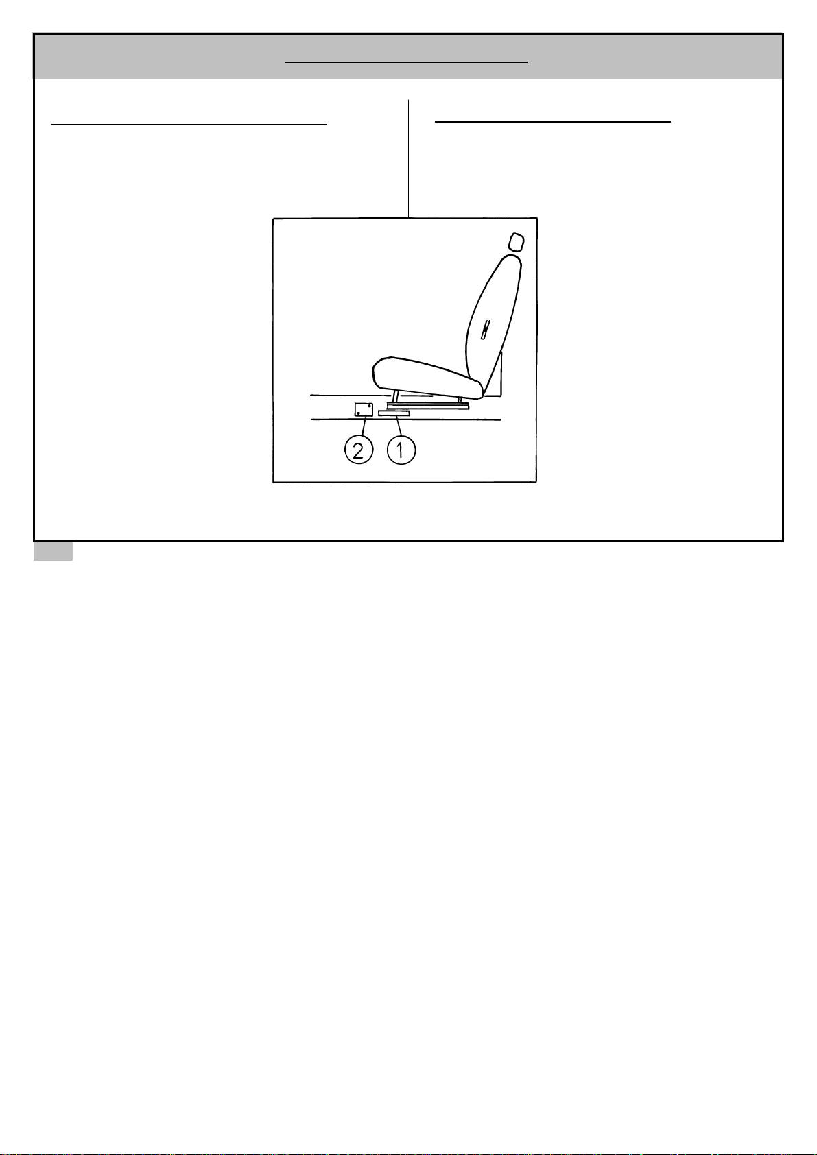
1 DOT MATRIX MARK ON CHASSIS
The number is etched on the right side of the
chassis in the interior of the vehicle under the
runner of the right hand seat.
VEHICLE IDENTIFICATION
2 MANUFACTURERS PLAQUE
The manufacturers plaque is riveted on the right side of
the bulkhead within the engine compartment.
Page 21
WELCOME ON BOARD Y
OUR NEW
17
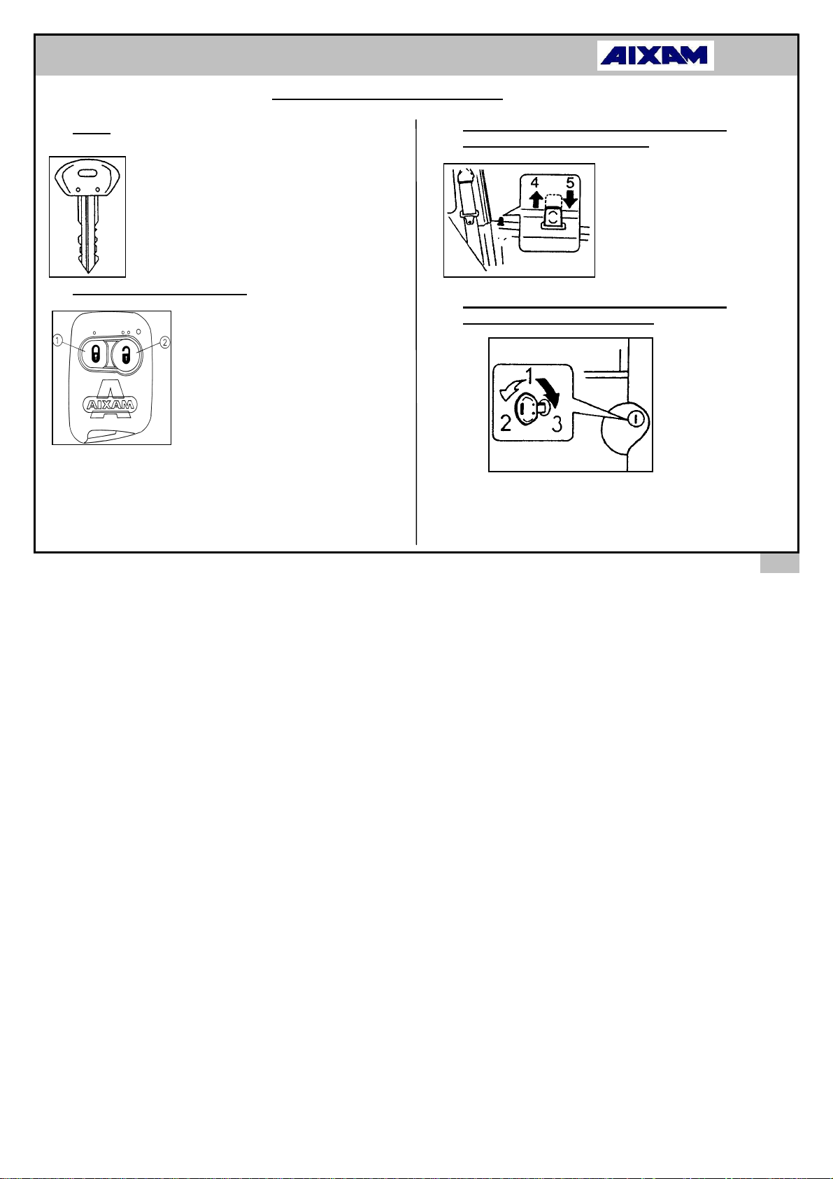
KEYS
Four keys are provided. Two keys pertain to
door locks and the two remaining
keys to the fuel tank cap.
REMOTE DOOR LOCKING
A remote locking fob is
provided. Press on the
button 1 to lock, and on the
button 2 to unlock. Each
press causes the sidelights
to flash.
NOTE: In case the remote
fob does not work, you can
always lock and unlock
using the keys.
LOCKING AND UNLOCKING*
LOCKING AND UNLOCKING FROM THE
INTERIOR OF THE VEHICLE
LOCKING AND UNLOCKING FROM THE
EXTERIOR OF THE VEHICLE
2. Lock
3. Unlock
4. Unlock
5. Lock
1. Insert the key
Page 22
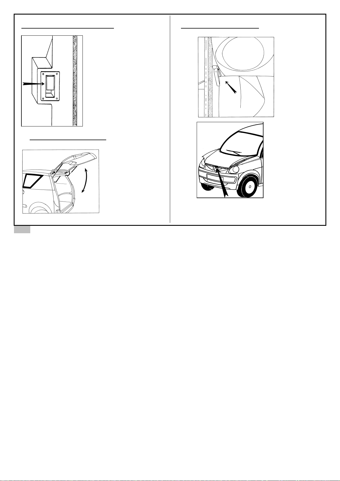
OPENING THE HATCHBACK
Pull on the handle
located adjacent to the
driver’s safety belt. Lift
the hatchback up to its
maximum position
without forcing. Both
gas strutts will keep it
open.
CLOSING THE HATCHBACK
Lower the
hatchback up to
three quarters of its
opening, then let it
down. Do not forget
to check if it is
properly locked
OPENING THE BONNET
Pull towards
you the lever
located under
the dashboard
on the left.
Lift the bonnet which
pushing on the
safety bolt. To
support the bonnet,
insert the bonnet
stay into the location
provided for the
purpose.
18
Page 23
19
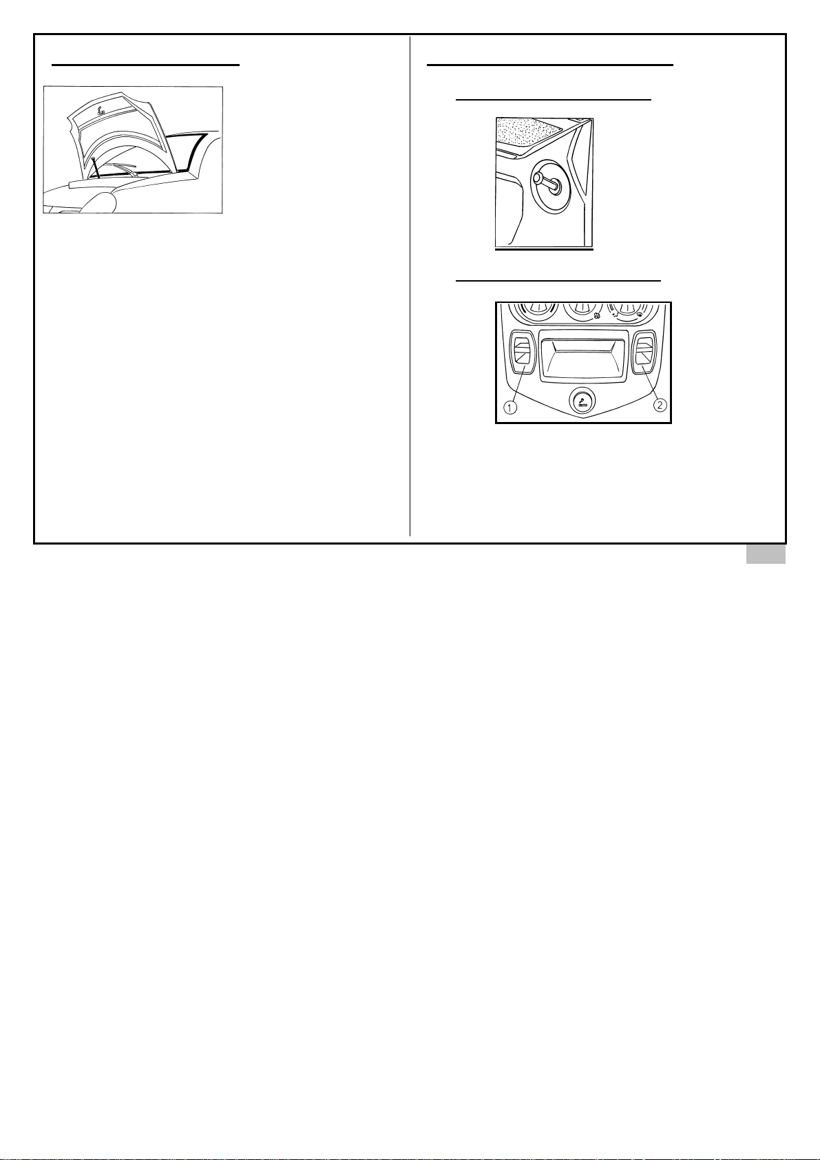
CLOSING THE BONNET
Release the bonnet stay and secure it. Then
lower the bonnet for about 50 cm and let it go so
that it closes by its own weight.
OPENING OF DOOR WINDOWS
MANUAL WINDOW CONTROL
ELECTRIC WINDOW CONTROL
The two electric window switches are located under the
central façade of the dashboard.
1. Switch for left window
2. Switch for right window
Page 24
20
SEATS AND SAFETY BELTS *
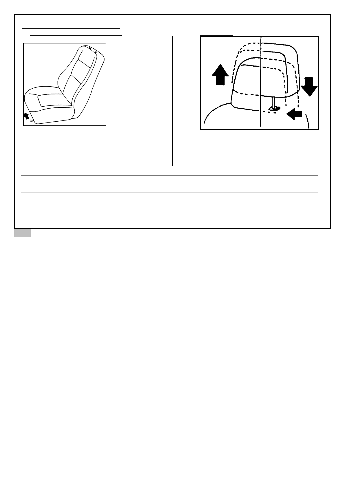
ADJUSTMENT OF FRONT SEATS
Adjust the
driver’s seat to
a position that
allows easy
operation of the
pedals, steering
wheel and
driving controls.
Lift the handle
and move the
seat forward or
back to the
appropriate position. After adjustment release the
handle in order to lock seat in position.
ATTENTION: - Adjust seat before driving.
- After adjusting ensure seat is securely in position.
HEAD REST
Push the control button and raise or lower the
head rest to suit occupant.
Page 25
21
SAFETY BELTS
T
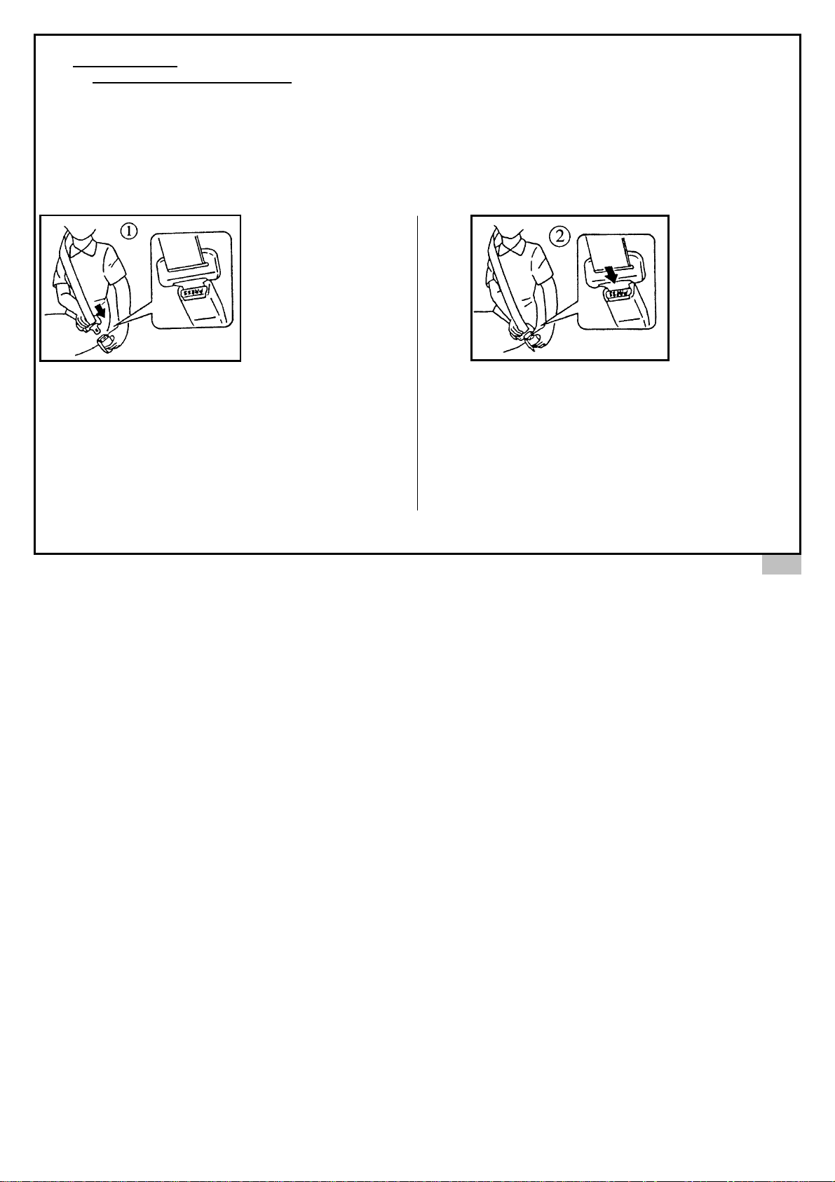
HREE-POINT FIXING SAFETY BELT
This type of safety belt can be adjusted to length. Once fastened, the belt will freely adjust to the user’s movements,
but in the event of a sudden jolt it will lock automatically to hold the body in position.
Before adjusting the length of the safety belt, first ensure that you are sitting comfortably in the seat and can operate
the pedals properly.
While attaching the seat belt, ensure that you are leaning back against the seat. The chest strap should be as close as
possible, without restricting the neck. The abdominal strap should be placed flat against the thighs and abdomen.
The safety belt should be placed directly against the body. Avoid overly thick clothing, sharp objects, etc…,
To fasten the seat belt, unroll the belt slowly and
without pause. Push the buckle into the lock until
you hear a light click. Adjust the belt if
necessary. If there is a block in the unrolling of
the belt, rewind the belt to the rest position and
unroll again.
To unfasten the safety belt, push on the red button and
release the buckle from the lock. As the safety belt
rewinds allow the belt to gently return to the rest
position.
Page 26
1.
SAFETY BELTS
• Safety belts must be worn at all times when the vehicle is in motion.
• You must adhere to local safety belt regulation.
• The safety belt was designed to hold one passenger. Never place a child on your knees and attach the safety belt.
• Never use a device that interferes with the straps (eg. clothes peg) because there is a greater risk of injury in an accident if
the safety belt is too loose.
• Following a serious accident, the safety belts in use at the time must be replaced. If any safety belt is faulty or damaged it
must be replaced immediately.
• If it is necessary to clean the safety belts, use only soap and water. All other cleaning products are prohibited.
• Improperly adjusted safety belts may cause injury in an accident. Pregnant women must wear a safety belt. Adjust the
abdominal strap to avoid putting too much pressure on the abdomen.
• When wearing safety belts ensure straps are not twisted.
• Do not attach the abdominal strap under the arm or behind the back.
• The safety belts were designed for use by occupants of adult height.
• Do not modify or alter the safety belt, its attachment to the vehicle or the seats.
• Only use the manufacturer’s original equipment.
• Babies and infants should never be transported on the knees of a vehicle occupant.
• It is particularly dangerous to strap in a child while he is seated on your knees. Never use one safety belt for more that one
person at a time.
• Never leave a child or animal in a vehicle exposed to the sun with the windows closed.
• Never leave the keys with a child in the vehicle.
22
Page 27
23
CHILD SAFETY
• The use of child’s safety seat for babies and children is required by law.
• It is imperative to follow the laws of the local area in which you are driving, particularly in respect to driving with children of
specific ages in the front seats of the vehicle.
• Generally, children younger that 12 years old, shorter that 1.5 metres or weighing less than 36 kgs, should be belted in
with an approved safety device adapted to the weight and height of the child.
• The driver is responsible for the correct and proper use of the child’s safety device.
• It is advised to choose an approved safety device that follows the European Regulation ECE 44.
• Child safety devices are obliged to carry an orange ticket with the letter E followed by numbers (dependant on the
authorised country) and the year of authorisation.
• Before using the child safety device, push back the vehicle seat to its maximum position.
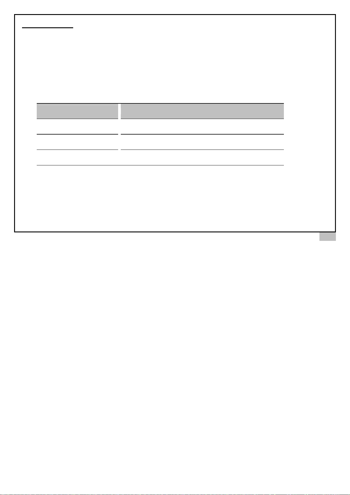
(AGE OF CHILD)
WEIGHT OF CHILD
(birth to 9 months approx.)
weight less than 13 kgs
(9 months – 3 years approx.)
weight 9kg - 18kg
(3 years - 12 years approx.)
weight 15kg - 36kg
• Before using the child’s seat, ensure that it is correctly installed in the vehicle. Follow the manufacturer’s installation
instructions supplied with the seat. Verify that the weight of the child correctly matches the seat specifications
AUTHORISED CATEGORY OF CHILD’S SAFETY SEAT
"U" universal (back facing to the front only)
"U" universal
"U" universal
Page 28
INSTRUMENTATION *
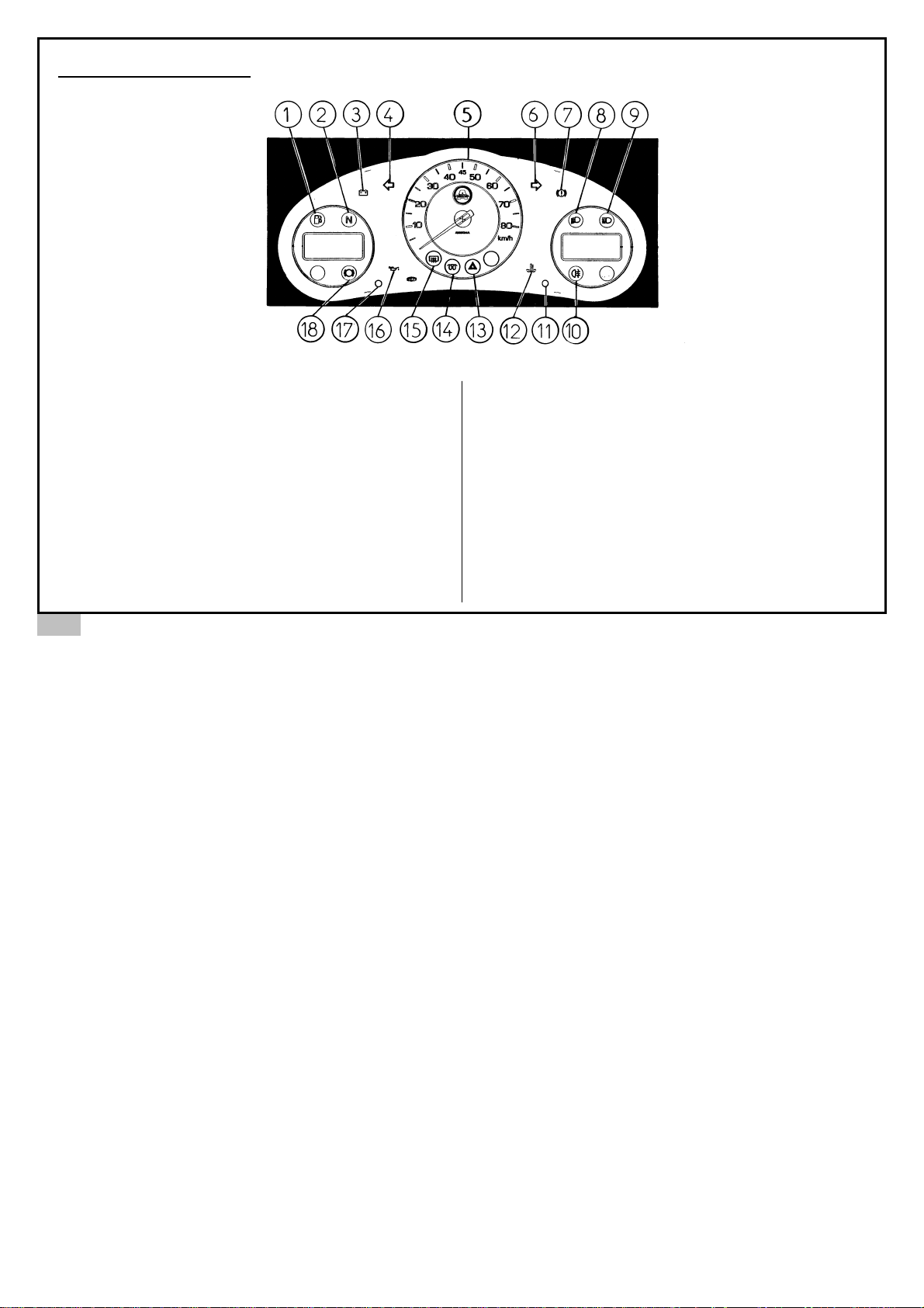
1. Fuel gauge
2. Neutral gear position indicator
3. Battery charge indicator
4. Left indicator
5. Speedometer
6. Right indicator
7. Handbrake light
8. Dipped headlights
9. High beams
10. Rear fog lights
11. Right setting button
12. Water temperature gauge
13. Hazard lights
14. Diesel engine pre-heat indicator
15. Rear window de-icing indicator
16. Oil pressure warning
17. Left setting button
18. Front brake pad wear warning light
* according to vehicle model
24
Page 29
25
INSTRUMENTATION*
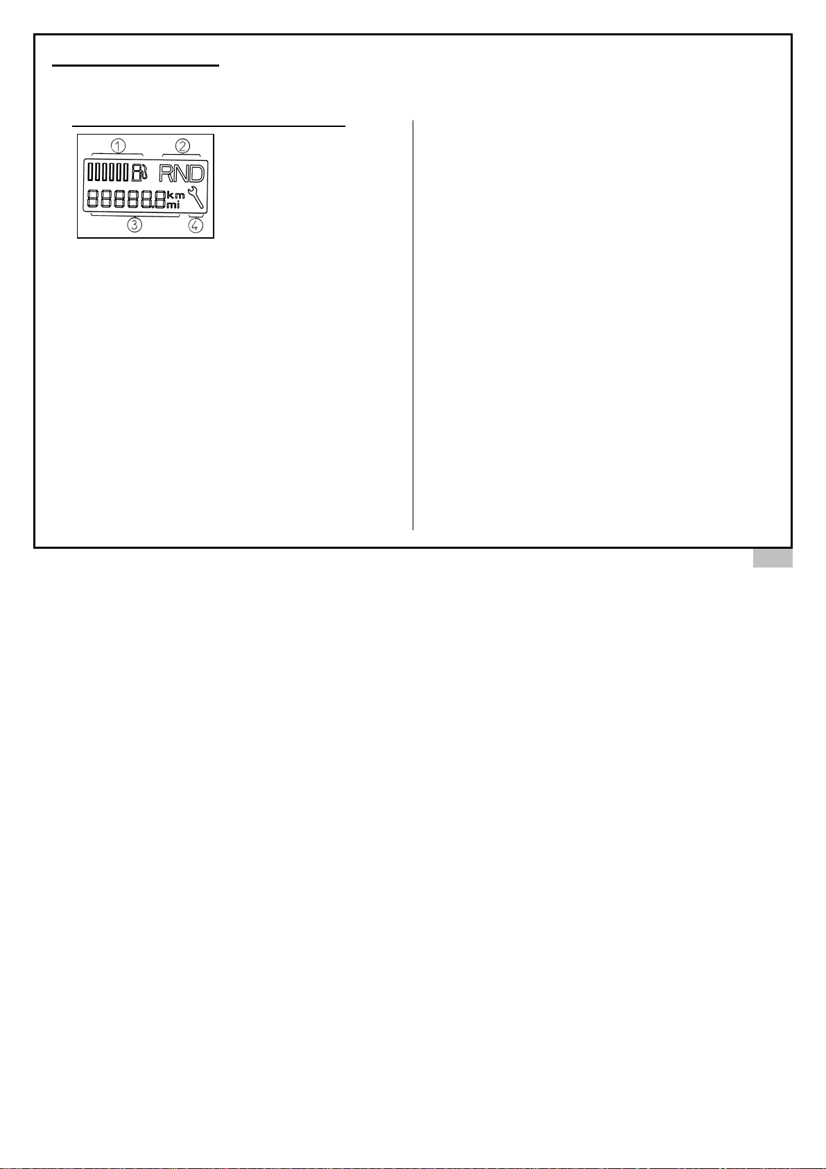
Depending on the vehicle model, there are 2 instrumentation panels, one with a single digital screen and the other with
two digital screens, one on the right and the other on the left.
MODEL WITH DIGITAL SCREEN ON LEFT
1. Fuel gauge
The fuel gauge is the
bargraph type (6 bars) and
as the level of fuel reduces
in the tank, the bars fall. The
fuel minimum is exhibited
when the last bar flashes
and the warning light (number 1 on previous page)
illuminates. If illuminated replenish fuel as soon as
possible.
2. Gear position indicator
Gear position indicator (forward, neutral, reverse). Coupled
with neutral, the indicator (number 2 on previous page)
illuminates.
3. Speedometer – partial or total (single screen model on
left of dashboard)
Total vehicle mileage display. To obtain a trip reading, push
the button (number 17 on the previous page) gently for a
few seconds, the trip meter will return to zero. To return the
speedometer push gently on the same button, push gently
again to return to the trip meter.
4. Trip meter and maintenance indicator
(two digital screen model, on right and left of
dashboard)
• The usage of the trip meter is the same as
explained in the previous paragraph.
• The maintenance indicator lets you to know in
advance when the vehicle is due for service. Two
parameters are used to calculate your next service:
the time and the mileage. For example, 1000 km or
1 year, 5000 km or 1 year. The maintenance
indicator displays the remaining distance to the
next service. Push the ‘key’ symbol marker 4 for 5
seconds. If the time for the next service has been
reached or is passed, the ‘key’ symbol, the mileage
and the indicator ‘-‘ flash for 5 seconds and the
‘key’ symbol remains displayed. If the time for the
next service has not yet been reached, the ‘key’
symbol and the message ‘1 year’ flashes for 5
seconds and the ‘key’ symbol remains displayed.
*
according to vehicle model
Page 30
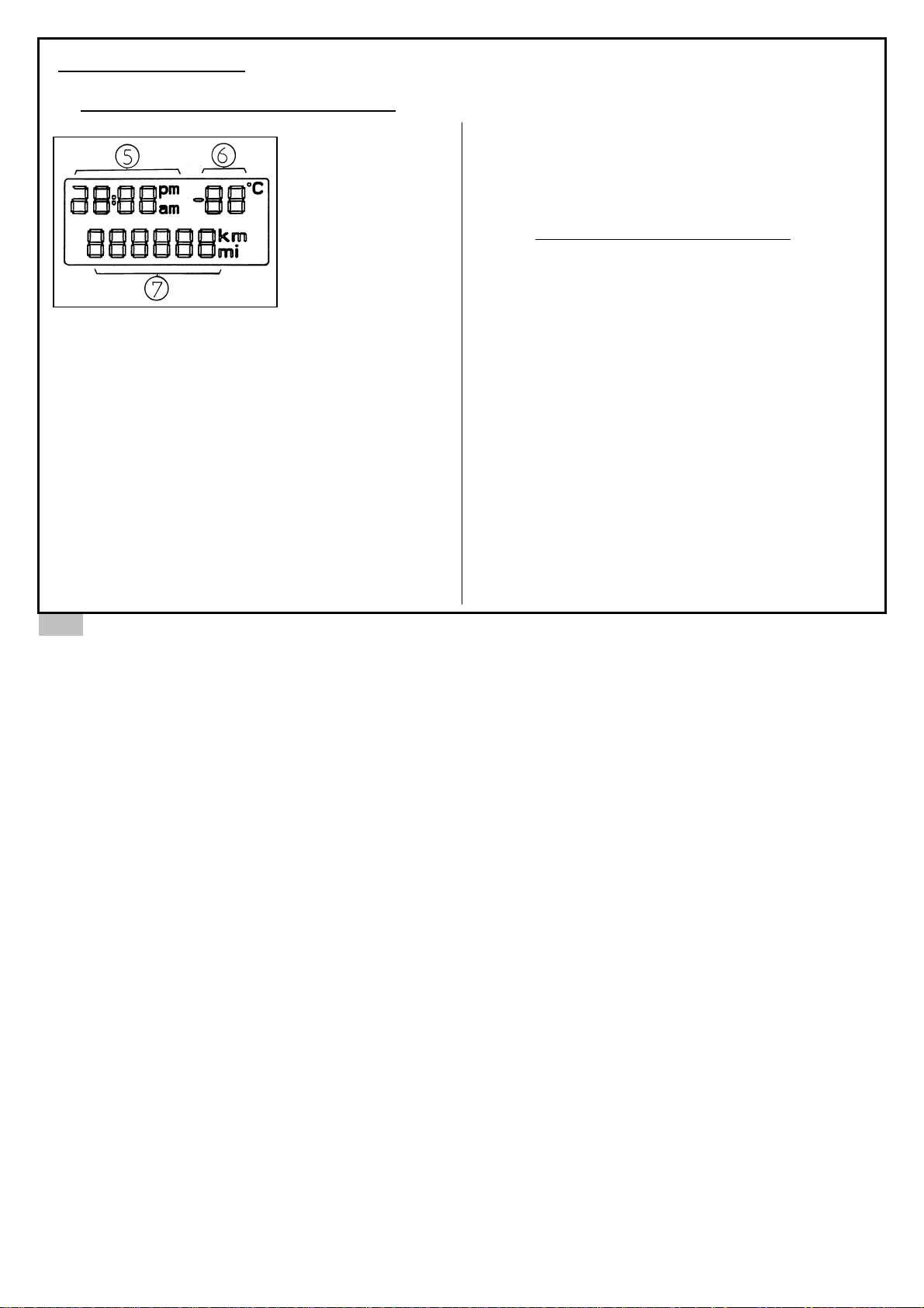
INSTRUMENTATION*
MODEL WITH DIGITAL SCREEN ON RIGHT
5. The clock:
The time can only be
adjusted when the
vehicle is at a full
stop. Adjust as
follows:
• Press the button 11 (see page 24) for 3 seconds
and the hours will flash
• Pulse the button to adjust the hours.
• Proceed in the same way to adjust the minutes.
To finish adjustment give a long press.
6. Temperature indicator: It flashes when the
temperature reaches 3 degrees to indicate a risk of
black ice.
7. Trip meter total:
Adjustment of instrumentation brightness
During the day when the lighting system is
extinguished, the lighting of the instrumentation can
not be regulated.
At night once the lighting is functioning you can
regulate the lighting of the instrumentation. To adjust,
press repeatedly on button 11 (see page 24). The
brightness will increase with each press until it reaches
maximum intensity and then will revert to minimum
intensity.
* according to vehicle model
26
Page 31
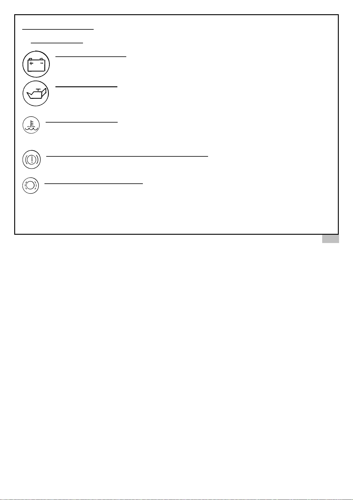
INSTRUMENTATION*
WARNING LIGHTS
Battery charge indicator: Should extinguish when the engine runs. If the light remains illuminated,
contact the nearest AIXAM service agent.
Oil pressure indicator: Should extinguish when the engine runs. If the light remains illuminated stop the
engine immediately. Check that the oil level is adequate and top-up if necessary. If light still remains on in
spite of proper oil level, contact your AIXAM agent as soon as possible.
Water temperature gauge: Should extinguish when the engine runs. If the light remains illuminated stop the
engine immediately. Leave the engine to cool down for 30 minutes before checking the level of coolant fluid,
taking all necessary precautions (there is a risk of severe burns). If the indicator illuminates when driving once
again, contact your nearest AIXAM service dealer.
Handbrake-on light and brake fluid level warning light: When lit, it indicates that the handbrake is
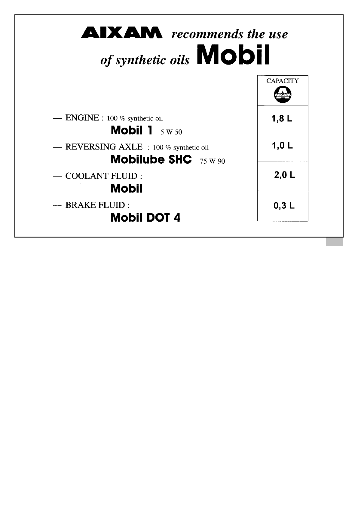
engaged or the brake fluid level is insufficient. Replenish with recommended brake fluid (see page 15).
Front brake pad wear warning light: If illuminated when braking then check pads or change without delay.
* according to vehicle model
27
Page 32

28
INSTRUMENTATION*
OTHER WARNING LIGHTS
Left indicator
Right indicator
Neutral gear position
Fuel tank reserve
Dipped headlights
Full beams
Rear fog lamps
Hazard lights
Heated rear window
Diesel engine pre-heating
* according to vehicle model
Page 33
29
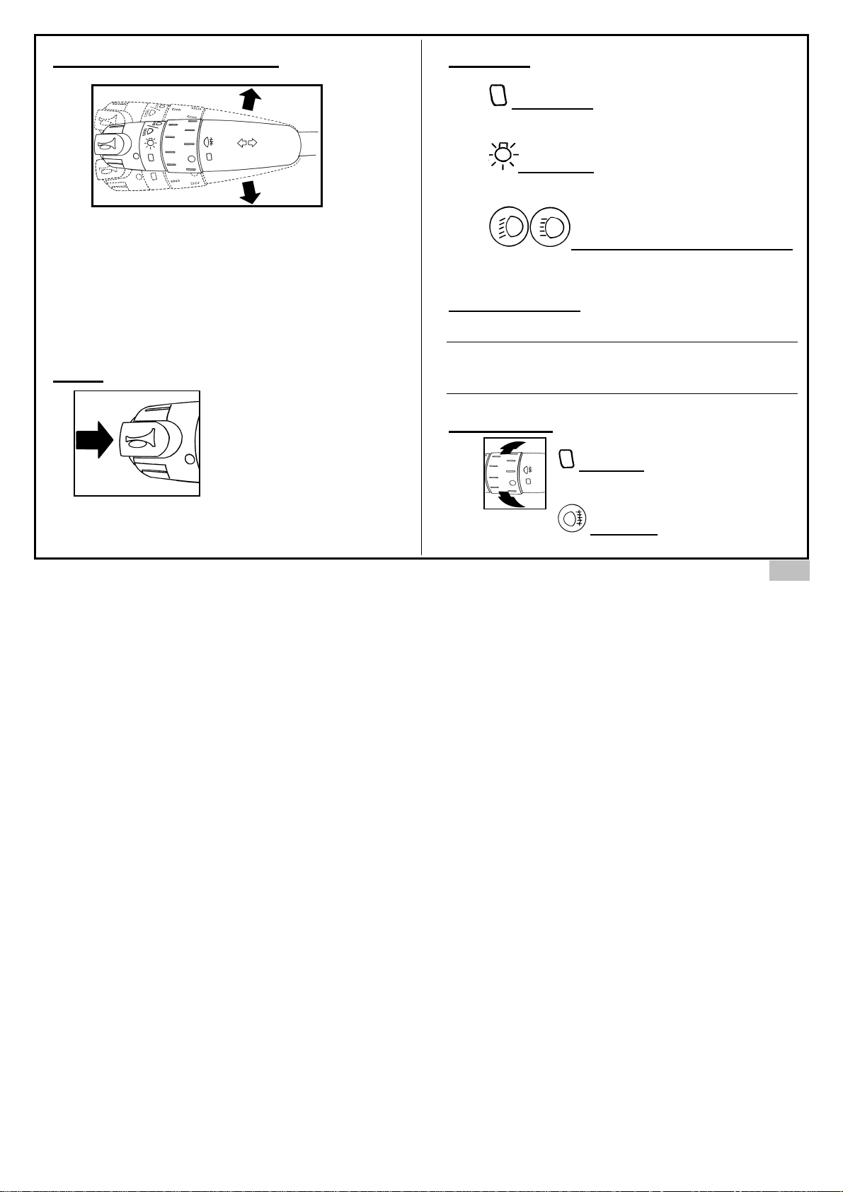
DIRECTIONAL INDICATORS
LIGHTING
HORN
• Press down for left direction
• Pull up for right direction
When changing direction, move the control in
the appropriate direction; the control will
return to its neutral position automatically
when the turn is complete.
For your safety, clearly indicate your
manoeuvres sufficiently in advance
Press on the end of the
control
All lights off
Turn the control forward
Side lights
Turn the controls forward
To change the lights from normal to full beam, pull the
lever towards you.
To flash headlamps
Pull towards you by pulses.
NOTE: Upon opening the door with the engine off, a
signal sounds to indicate that the lights have not been
extinguished
Dipped headlights / on full beam
FOG LIGHTS
Lights off
Turn the control forward
Fog lights
Page 34
30
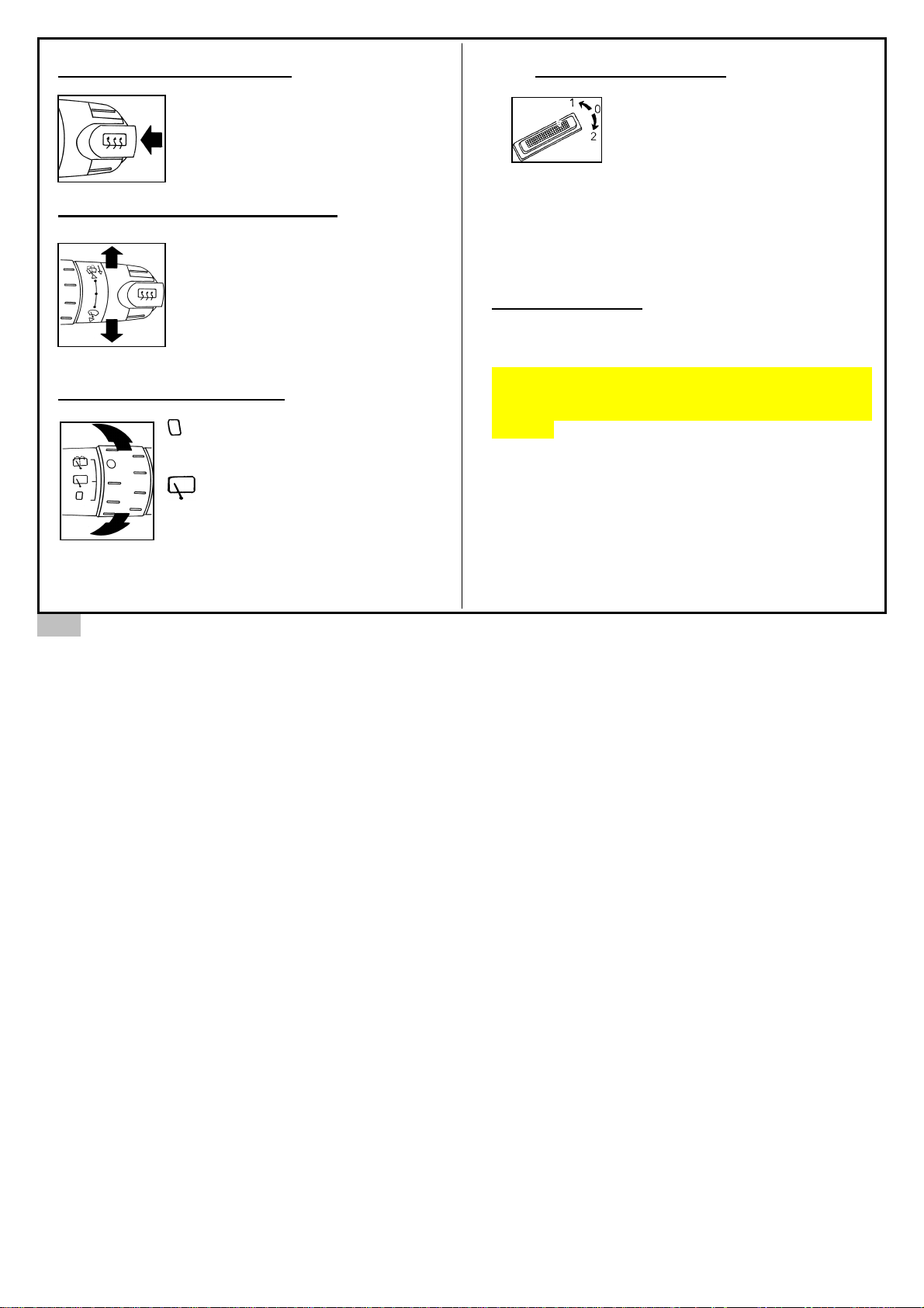
HEATED REAR WINDOW *
To start, push on the end of the
control. It will continue working
for 12 minutes.
FRONT WINDSHIELD WIPERS *
- The windscreen wiper wipes
once when the control is pressed.
- Lift the control:
1. stop
2. slow speed
3. fast speed
Pulling lever towards you operates the
windscreen wash facility
REAR SCREEN WIPERS *
rear wipers off
turn the controls to the front
rear wipers on
INTERIOR LIGHTING*
0. Off
1- Permanently on.
2- Door controlled light.
When the door is opened the interior light will increase
in brightness and will stay illuminated for 30 seconds.
When the door is closed the light will remain on for 10
seconds then dims.
HAZARD LIGHTS
The control operates the four indicator lights
simultaneously. Use only in case of emergency.
In case of a sudden deceleration (such as sudden
braking) when the vehicle is moving, will cause the
warning lights to automatically illuminate for 10
seconds.
Page 35
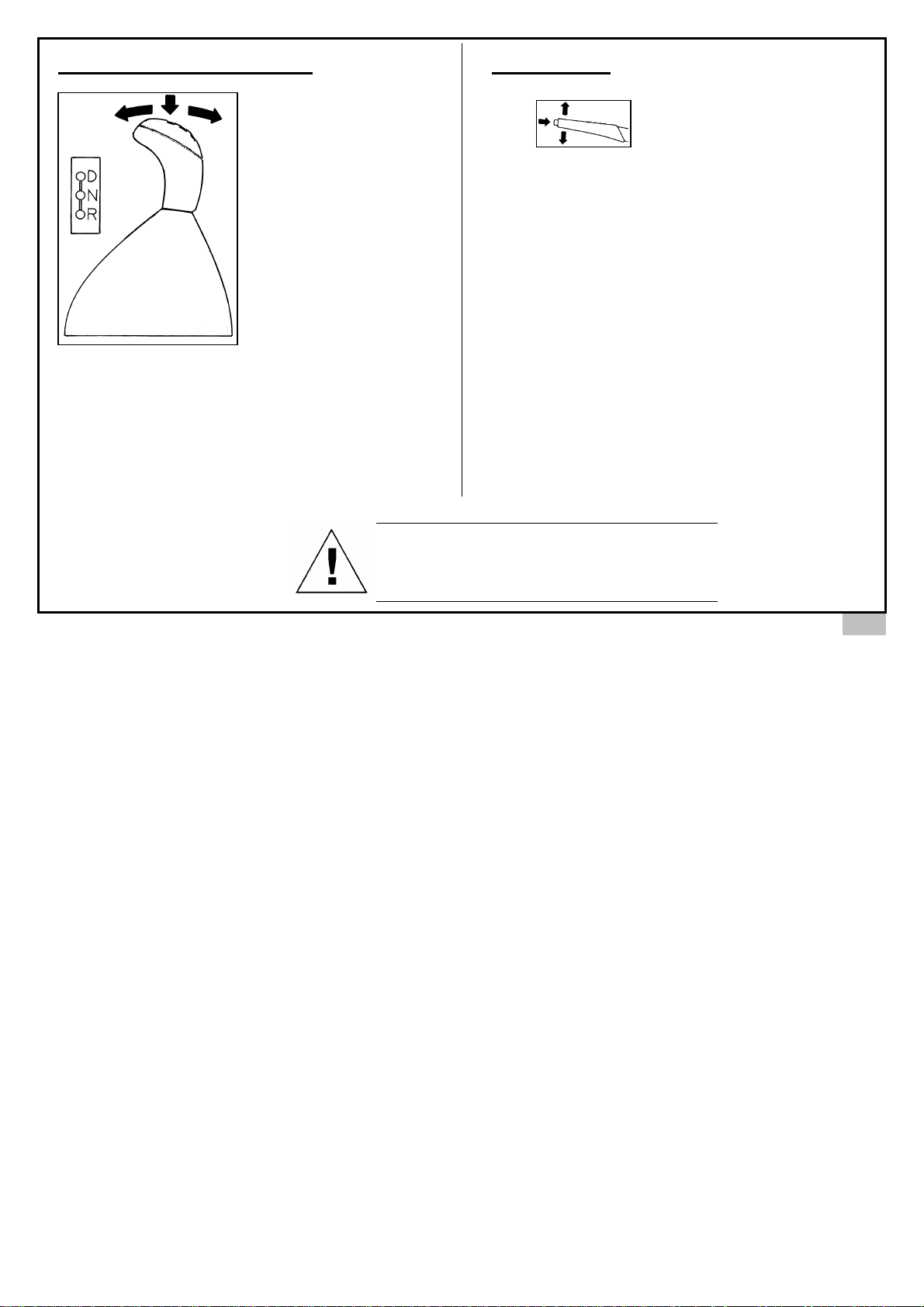
TRANSMISSION SELECTION
N = Neutral
D = Forward gear
R = Reverse gear
To select the desired gear:
1. Push the lever down and forward to select the
forward gear.
2. Pull lever back to engage neutral from forward
gear.
3. Push lever down and back and then pull lever
upwards to engage and lock reverse gear.
HANDBRAKE
To park bring the vehicle to a
complete halt and apply the
handbrake.
1. To apply the handbrake, pull the handle upwards
without pressing the button on the end of the handle.
2. To disengage, pull the lever gently upwards, press on
the button on the handle and lower the handle.
To select the gear, it is imperative that:
- The vehicle is at a complete stop;
- The engine is at idle speed
31
Page 36
32
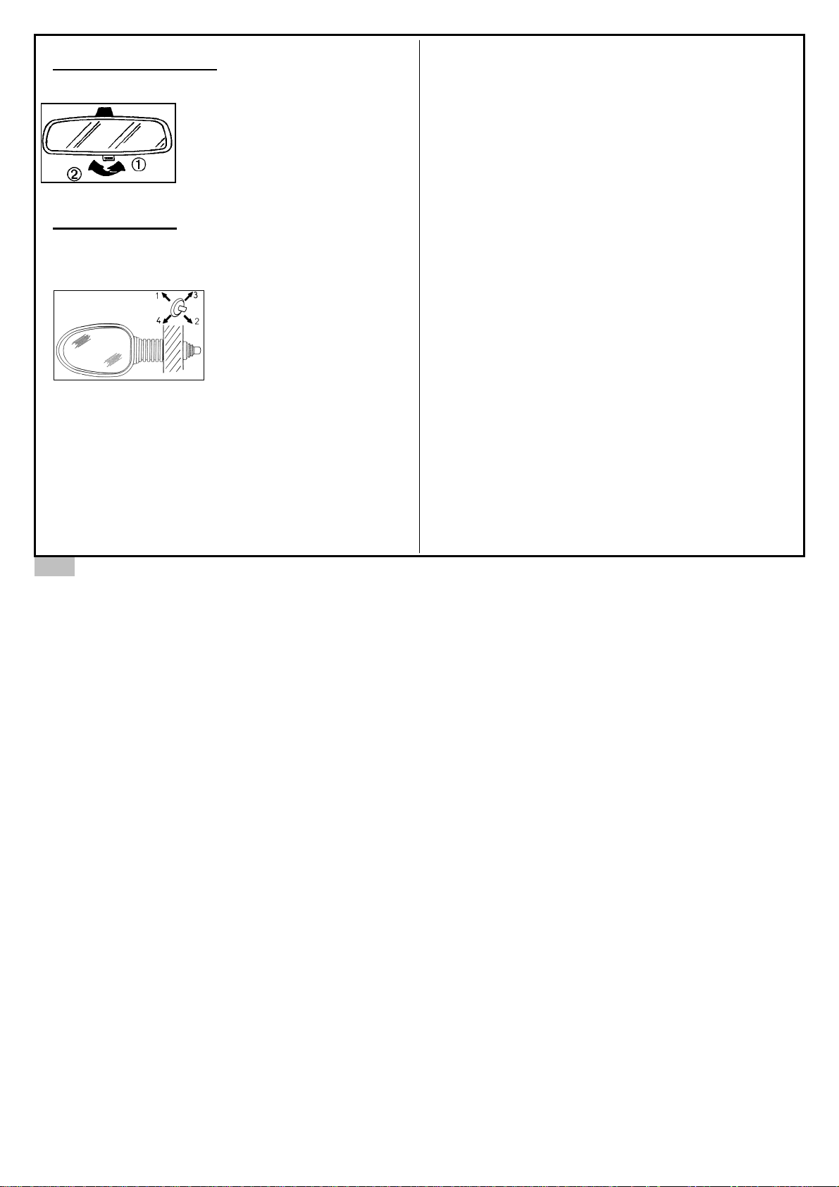
REARVIEW MIRROR
The control is located on the lower part of the mirror
and can adjust the mirror to
reduce the dazzle of headlights
from following vehicles at night.
1. Normal
2. Anti-dazzle
DOOR MIRROR
The door mirror adjustable using the button lever
located on the inside of the door.
1. upwards adjustment
2. downwards adjustment
3. right adjustment
4. left adjustment
Page 37
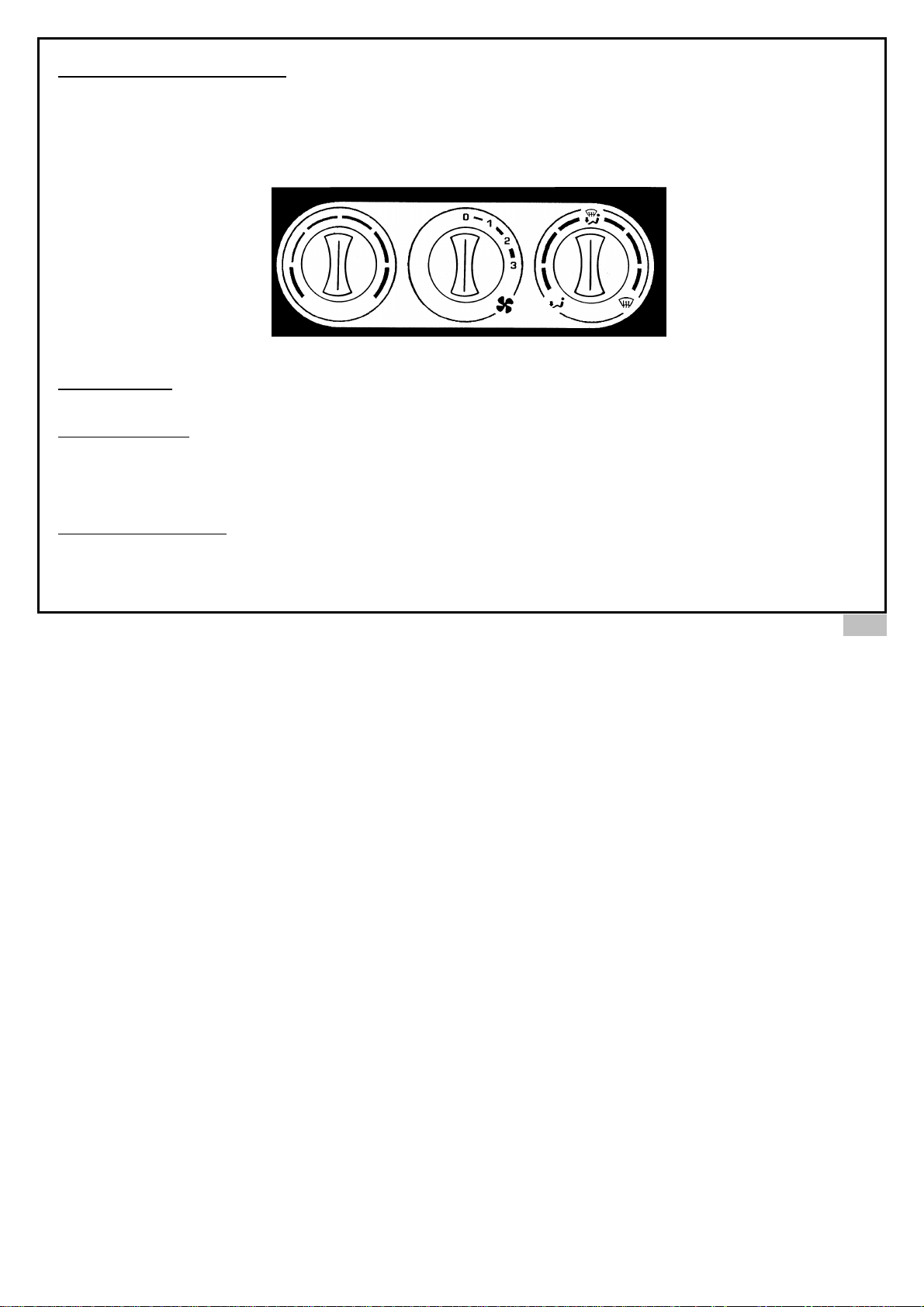
HEATING – VENTILATION
The heating only works when the engine is running. The performance is directly dependent on the temperature of the
engine. Therefore it is recommended to use the heating only when the engine has reached its normal operating
temperature. It is ineffective to start up the engine and leave it to idle for a few minutes because the heating does not
work when the engine is idling.
1. Heating switch
Turning the switch to the right increases the heat in the cabin.
2. Ventilation switch
0. Off
1. Low speed
2. Medium speed
3. High speed
3. Air flow direction switch
Turning the switch to the left directs the air flow downwards towards the floor. Turning the switch to the right directs the air flow
upwards to demist the windscreen. Close the two central vents to increase air to the windscreen demist position.
33
Page 38
34
HEATING - VENTILATION
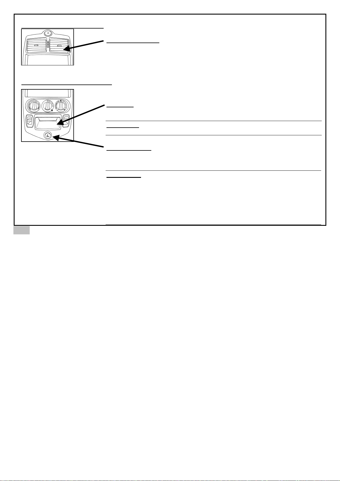
CIGAR LIGHTER, ASHTRAY
VENT REGULATOR
+ open - closed
The vents are permanently fitted onto the grills in order to direct the flow of air
(up/down, right/left).
ASHTRAY
Pull forwards to open. To remove the ashtray grip the protruding handle and pull
forward.
ATTENTION: When you empty the ashtray, be sure there are no embers
because they are a fire hazard.
CIGAR LIGHTER
Push the cigar lighter in until it stops. It is ready to use when it pops back into its
normal position an emits a gentle click. To use, remove the cigar lighter from its
compartment.
ATTENTION:
- Hold the cigar lighter by the button. Do not touch the metal casing, which
can burn.
- Only use the original cigar lighter supplied with the vehicle, use of any other
may be a fire hazard.
- Once the cigar lighter is pushed in, it should pop back into its normal
position within 30 seconds. If it does not then it is faulty and should be
pulled out immediately, as it is a fire hazard.
Page 39
35
RECOMMENDATIONS FOR ‘RUNNING IN’
THE VEHICLE
To ensure the vehicle remains reliable and
economical, drive the vehicle as follows during
the ‘running in’ period of the first 1000 km.
• Do not drive the vehicle at high speeds
• Avoid rapid starts and accelerating and
braking excessively
FUEL
FUEL USED
Diesel fuel (DIN 51601)
REFUELING
1. Stop the engine before refuelling.
2. Unlock and remove the fuel cap.
3. Insert the refuelling nozzle.
4. After the automatic interruption in the flow of fuel from
the service station pump do not continue to add fuel for
longer than 5 seconds.
5. Remove the nozzle.
6. Replace the fuel cap and lock.
Attention:
The fuel is explosive and flammable. Extinguish all
flames and abstain from smoking.
Page 40
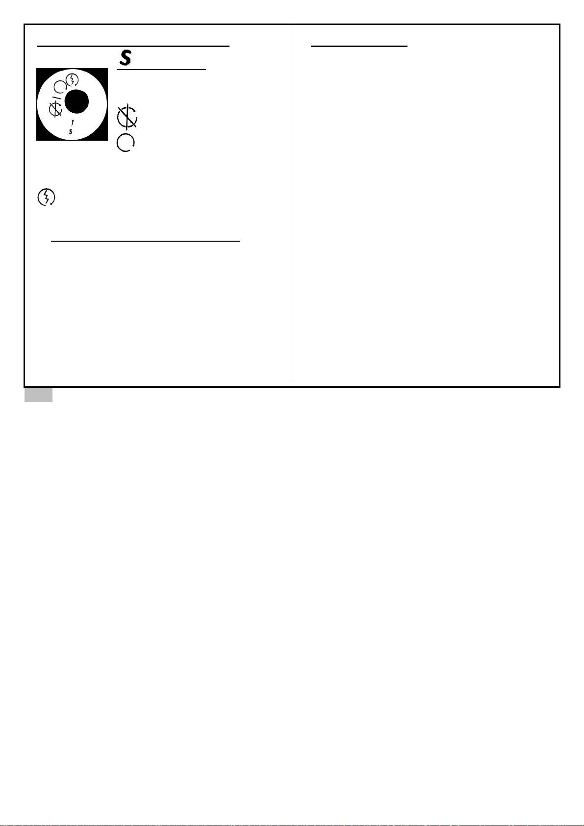
CONTACT, STARTING CONTROLS
ANTI-THEFT
To release the steering, lightly
manoeuvre the steering wheel
while turning the key gently.
ACCESSORIES
RUNNING POSITION
The contact is made. Do not leave the control in
this position when not using the vehicle: the battery
may discharge.
STARTER
Start position, release when engine starts.
STARTING AND STOPPING THE ENGINE
• Check first the handbrake is engaged and the
gearshift lever is in neutral.
• Put the key into the ‘contact’ position and wait until
the engine pre-heating light is off.
• Start the engine by turning the key to the ‘start’
position, then release the key.
• To stop the engine, return the key to the ‘anti-theft’
position.
DRIVING ADVICE
Before departing check:
- Position of rear-view mirror
- Seat position
- Fuel level
Put on and adjust safety belt.
Drive using only one foot to avoid using both pedals
(accelerator and brake) at the same time, which will
avoid premature wear of both transmission and braking
systems.
Reduce engine speed on descents.
If you need to mount a curb, carefully mount at the
lowest possible point or else you risk damaging the
suspension and prematurely wearing out the tyres.
36
Page 41
VEHICLE CARE
ATTENTION
The use of chemical products can be dangerous.
Some are toxic; others ignite close to an open flame
or heat source. In poorly ventilated areas, inhalation
of the fumes of particular substances can cause
illness or poisoning. Read and follow directions
carefully for all chemical products. When using
ensure proper ventilation by opening doors and
windows.
The following products are prohibited for use on the
vehicle:
- Petrol - Benzene
- Naphtha - Carbon tetrachlorine
- Acetone - Paint thinners
- Teretentine essence - Varnish thinners
- Nail varnish remover - Etc….
These products are dangerous and risk damaging
the vehicle.
CLEANING THE CABIN
- Vacuum the cabin to remove dust.
- Clean plastic panes with soap and water.
- Clean the upholstery and carpets with cleaning
products designed for that use.
CLEANING THE BODY
Immediately clean the vehicle if it is exposed to
elements that may corrode, discolour or stain the body,
notably:
- Sea water or chemical products used for de-icing the
roads in winter.
- Soot and dust, ash, chemical products (acids, tars,
etc…)
- Bird droppings, insect debris, tree resin, etc…
CLEANING
- Use only liquid soap and water.
- Avoid direct sun or freezing temperatures.
- Do not use automatic car washes.
- Do not use steam or pressure washes.
CLEANING OF WINDOW AND GLASSES
Clean windows with soap and water or a suitable glass
cleaner, taking care to avoid contact with the vehicle
body.
37
Page 42
SPARE TYRE
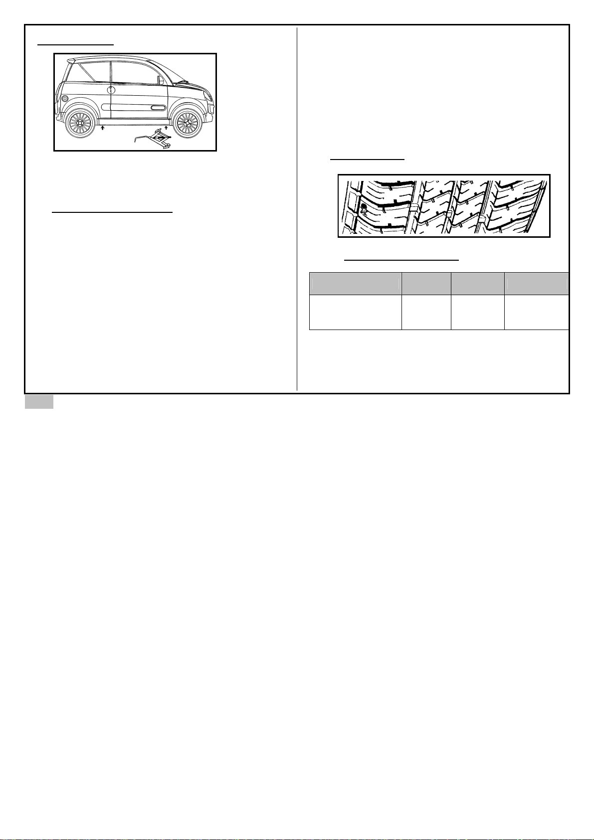
The vehicle is equipped with a spare tyre
underneath the rear boot, a jack situated in a
box within the interior of the spare tyre and a
wheel brace under the front right hand seat.
CHANGING A FLAT TYRE
- Park the vehicle on firm flat ground.
- Engage the handbrake or wedge the vehicle
wheels.
- Remove the spare wheel from its
compartment
- Remove the jack from its box.
- Loosen the wheels nuts with the wheel
brace.
- Place the jack under the vehicle taking care
to support the main chassis structure of the
vehicle and avoid the underside of the floor
panels
- Raise the vehicle by turning the jack handle.
- Remove the nuts.
- Remove the wheel.
- Put on the spare tyre, replace and tighten the nuts
firmly before lowering the vehicle.
- Store and secure the flat tyre in the spare tyre
compartment.
- Repair the flat tyre, making sure to check the air
pressure is correct and then as soon as possible
replace the spare wheel on the vehicle
TYRE STATE
TYRE PRESSURE (BAR)
TYRES FRONT REAR SPARE
KLEBER
145 / 70 R 13
1.6 1.6 1.7
38
Page 43
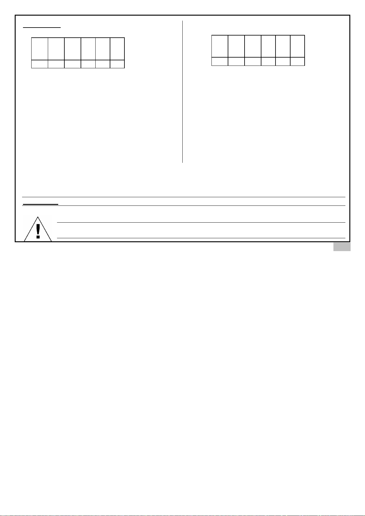
FUSE BOX
20 A 20 A 15 A
10 A 15 A 20 A 25 A 20 A
C18 C18 C18 C18 C18 C18
1 2 3 4 5 6
1. 20 AMP fuse: stop motor and rear windscreen
defrost
2. 20 AMP fuse: interior lighting, warning alarm,
headlights, full beam, sidelights, indicators and fog
lights.
3. 15 AMP fuse: central locking, radio, cigar lighter,
wr module and instrument panel.
4. Not in use
5. Not in use
6. Not in use
1. 10 AMP fuse: Instrument panel and de-icing relay.
2. 15 AMP fuse: alternator, pre-heat relay, brake light.
3. 20 AMP fuse: windscreen wipers, reversing light and
cabin heater.
4. 25 AMP fuse: right and left electric windows and central
locking.
5. 20 AMP fuse: pre-heating.
6. Not in use.
ATTENTION: When you change a fuse, always use the correct amperage (fire risk)
To recharge the battery, it is imperative to remove the battery from the vehicle and charge it in a
ventilated area.
C19 C19 C19 C19 C19 C19
1 2 3 4 5 6
39
Page 44
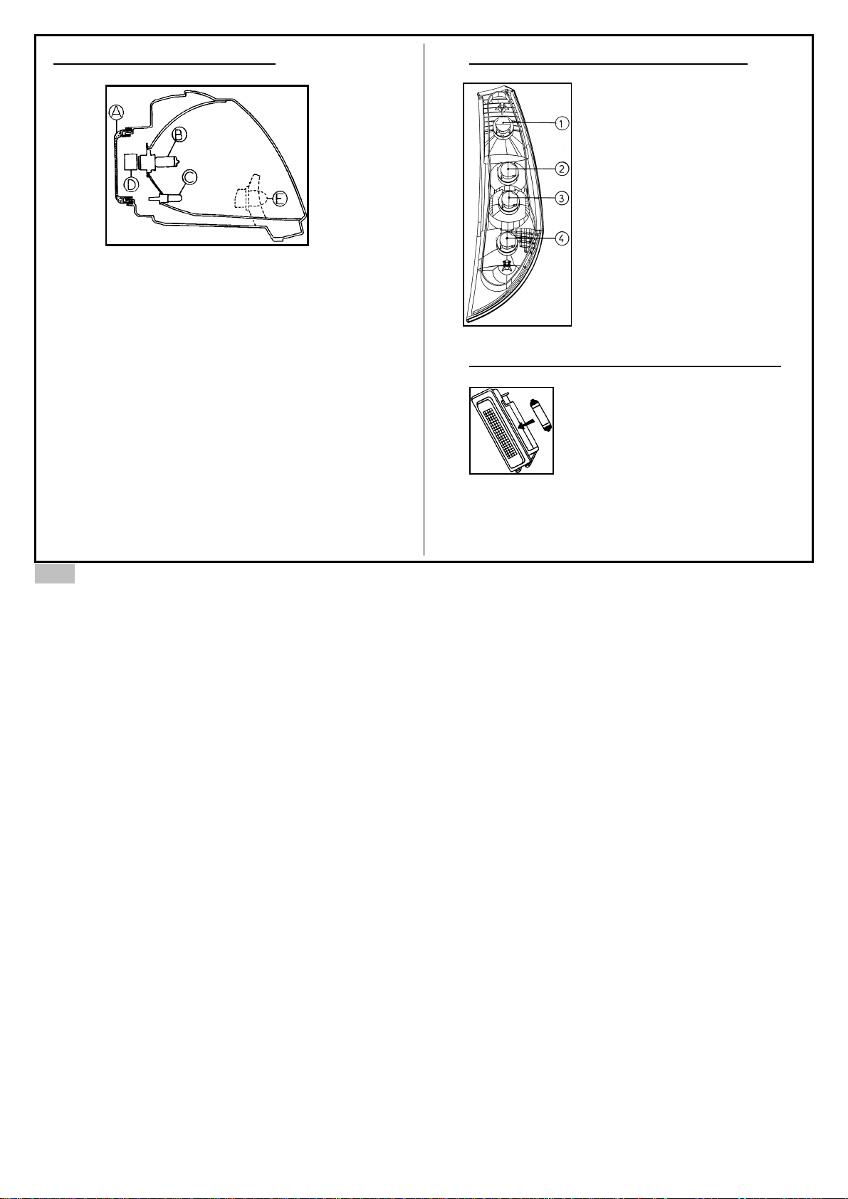
REPLACEMENT OF BULBS
- Unclip protection ‘A’ behind the light situated in
the wheel arch, by pivoting to the left.
- Take out connector ‘D’ which is connected to the
main beam and dipped beam headlamps ‘B’.
- Press and re-tighten the steel wire which
supports the lamp bulb, take out bulb ‘B’ and
replace.
- To remove the side light bulb ‘C’, pivot the
connector to the left.
- Remove the bulb from the connector by pulling
on it.
- Follow the instructions in reverse order to
reassemble and ensure that protection ‘A’ is
correctly remounted
- To replace the indicator bulbs ‘E’, pivot the lamp
support, situated in the wheel arch, to the left,
remove and replace the bulb. Follow the
instructions in reverse order to remount.
REPLACEMENT OF REAR LIGHTS
- Open the tailgate.
- Remove inspection cover on inner
wing panel.
- Undo the connector.
- Remove and replace the bulb.
1. Rear and stop lights
2. Indicator light
3. Reverse light
4. Rear fog light
REPLACEMENT OF INTERIOR LIGHTS
Unclip the lamp from its support on
the ceiling to replace the bulb.
40
Page 45
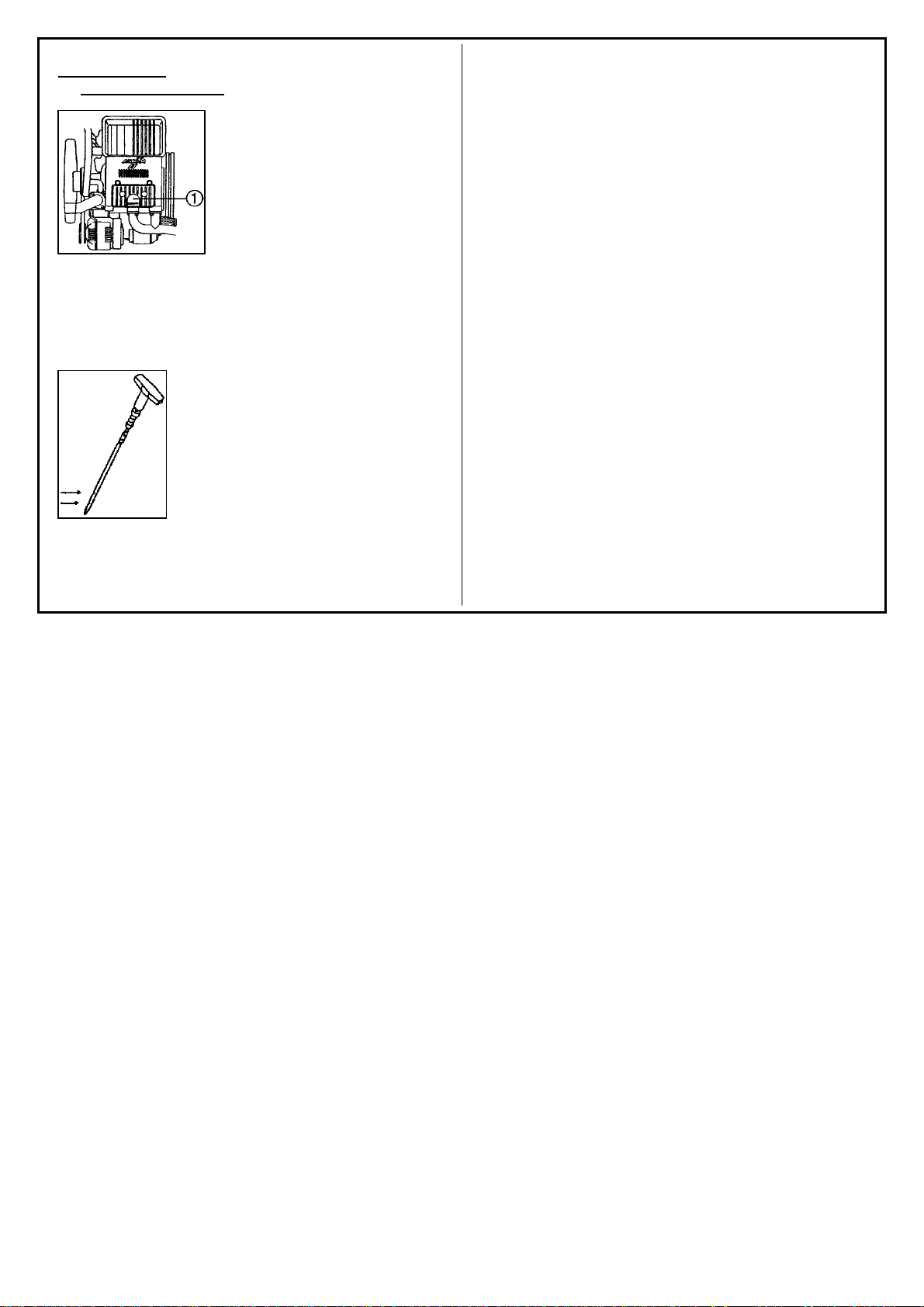
ENGINE OIL
ENGINE OIL LEVEL
All engines consume a small
quantity of oil. It is therefore
important to check the level
of oil at regular intervals or
before a long journey.
Perform the check with the
engine warm and the vehicle
stationary. Park the vehicle
on a flat surface and stop the engine. Wait a few
moments to allow the oil to settle, in order to give a
true and exact measurement of the oil.
Take out the dipstick and wipe with a clean cloth.
Put it back in as far as it will go. Take it out again
and read the quantity shown
between the two marks. If the level
of oil is less than the maximum
limit remove the oil filler cap and
replenish to the maximum limit with
the specified oil (page 15).
Replace the filler cap securely.
Page 46
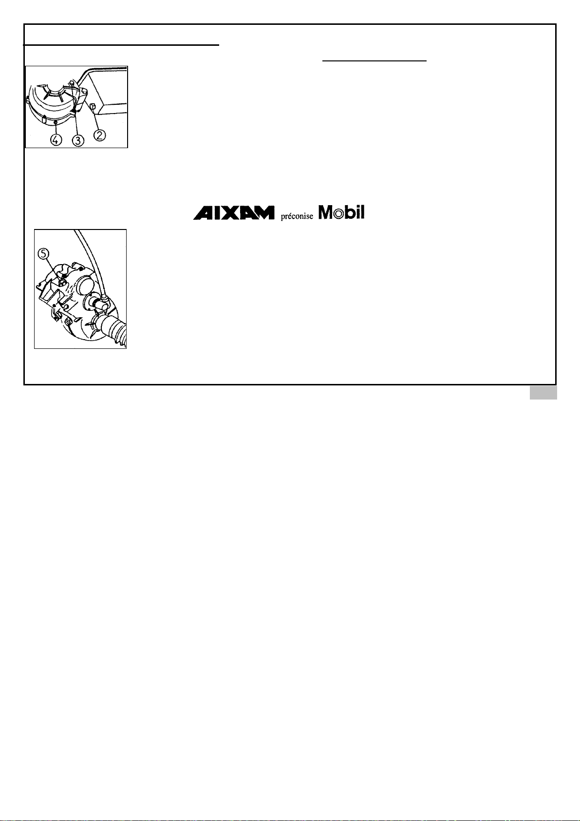
EVERY 5000 km CHANGE ENGINE OIL
- The engine must be warm.
- Remove the filler cap ‘1’.
- Unscrew the sump plug ‘2’ and
let the oil drain out.
- Change the washer sump plug.
- Fasten the sump plug.
- Fill the engine with oil
according to the quantity
indicated (page 15)
- Check the oil is at the proper level using the dip
stick.
- Carefully close the filler cap.
REVERSING AXLE OIL
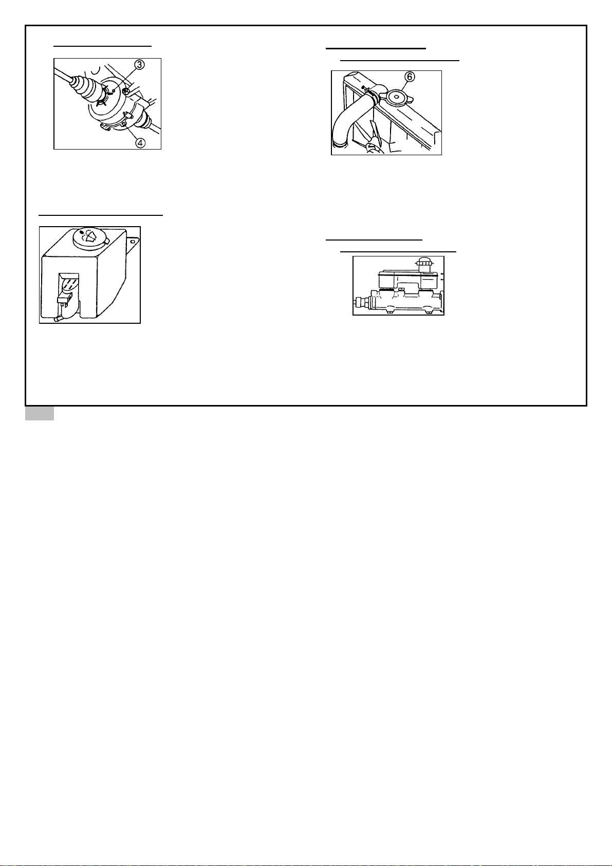
‘5’ Filler cap
41
Page 47
42
TRANSMISSION OIL
3. Level plug
4. Drain plug
Every 10,000 km
change the
transmission oil.
Operation to be performed after having used the
vehicle. Always fill to the precise level indicated
(page 15).
WINDSCREEN FLUID
Fill with alcohol-free
windscreen wash fluid.
COOLANT FLUID
COOLANT FLUID LEVEL
-Must be checked when the
engine is cold to prevent
burning.
-.The coolant fluid must cover
the upper grill of the radiator.
-.To check, remove the radiator
cap ‘6’.
-.Replace the radiator cap securely.
NB : It is important to replace the coolant every 2
years.
BRAKING FLUID
BRAKING FLUID LEVEL
- The level must be between
the two marks.
- Fill up if necessary (see page
15).
NB : It is important to replace the brake fluid every 2
years.
Page 48

In case of vehicle breakdown outside
your dealer’s region
please call 04 79 61 42 45,
tell us in which region you are located
and we will inform you of
the nearest AIXAM service agent.
OAA 106
Page 49
Page 50
Page 51

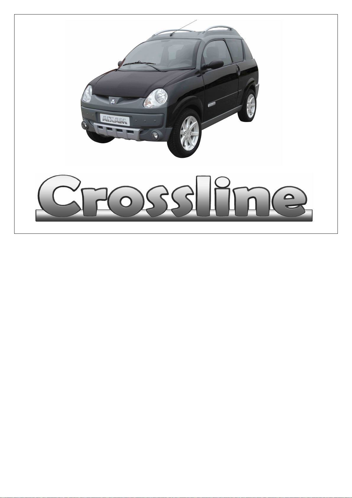
The maximum
admissible load on the roof bars is 35
DIRECTLY ONTO THESE
FOR YOUR SAFETY AND FOR OTHER
ROAD USERS ENSURE THAT YOUR
LOAD IS SECURED CORRECTLY ON
THE ROOF BARS BEFORE SETTING
SPECIFICATION
Length = 3050 mm
Width = 1474 mm
Height = 1570 mm +/- 20 mm
Front overhang = 471 mm
Rear overhang = 615 mm
Wheelbase = 1960 mm
Front track = 1285 to 1300 mm
Rear track = 1265 to 1280 mm
ATTENTION :
kgs.
DO NOT LOAD
BARS BUT USE CROSS BAR KITS
THAT ARE AVAILABLE FROM MOST
RETAIL OUTLETS.
OFF.
0AE101
 Loading...