


REPAIR MANUAL

CONTENTS
GROUP 0: GENERAL
|
General warranty terms..................................................................................................................................... |
2 |
Technical characteristics :
|
- |
Light quadricycles category L6e ........................................................................................................................ |
3,4 |
|
- |
Heavy quadricycles category L7e ..................................................................................................................... |
5,6 |
|
Checks to perform before delivering the venicle ............................................................................................... |
7 |
|
|
Work to perform during servicing....................................................................................................................... |
8 |
|
|
Vehicle identification ......................................................................................................................................... |
9 |
|
GROUP 1: ENGINE
KUBOTA Z402, Z602 engines
- Cooling system................................................................................................................................................... |
2 |
- Lubrication system ............................................................................................................................................. |
3 |
- Injection system ................................................................................................................................................. |
4 to 7 |
- Tightening torques Z402 .................................................................................................................................... |
8 |
- Tightening torques Z602 .................................................................................................................................... |
9 |
- Repairs............................................................................................................................................................... |
10 to 12 |
LOMBARDINI 523 MPI engine
|
- Cooling system................................................................................................................................................... |
13 |
|
- Lubrication system ............................................................................................................................................. |
14 |
|
- Injection system ................................................................................................................................................. |
15 |
|
- Tightening torques ............................................................................................................................................. |
16, 17 |
|
- Repairs............................................................................................................................................................... |
18 |
GROUP 3: REVERSER AXLE |
|
|
|
Reverser axle .................................................................................................................................................... |
2 |
|
Transmission..................................................................................................................................................... |
3 |
|
Regulator assembly VSP 2000 LP2 version 2................................................................................................... |
4 to 23 |
GROUP 4: FRONT AXLE |
|
|
|
Front axle adjustment dimensions |
|
GROUP 5: REAR AXLE |
|
|
|
Rear axle adjustment dimensions |
|
GROUP 6: WHEELS-BRAKES |
|
|
|
Tire pressure ..................................................................................................................................................... |
2 |
|
Renewing the brake fluid................................................................................................................................... |
3 |
|
Brakes ............................................................................................................................................................... |
4, 5 |
|
Hand brake........................................................................................................................................................ |
6 |
|
Summary on aluminum wheels 2010 ................................................................................................................ |
7 |
GROUP 7: BODY |
|
|
|
Front frame dimensions CITY ........................................................................................................................... |
2 |
|
Aluminum cell dimensions CITY........................................................................................................................ |
3 to 5 |
|
Front frame dimensions CROSSLINE ............................................................................................................... |
10 |
|
Aluminum cell dimensions CROSSLINE ........................................................................................................... |
11 to 13 |
|
Body maintenance............................................................................................................................................. |
18 |
|
Gluing................................................................................................................................................................ |
19 |
GROUP 8: ELECTRICITY-INSTRUMENTS |
|
|
|
Instrument cluster.............................................................................................................................................. |
2 to 20 |
|
Fuses ................................................................................................................................................................ |
21 |
|
Centralised locking ............................................................................................................................................ |
22 |
|
Guarantee on CLARION radio unit.................................................................................................................... |
23 to 26 |
|
Changing a lamp ............................................................................................................................................... |
27, 28 |
|
Electric diagram ................................................................................................................................................ |
29 to 33 |
|
Air conditioning.................................................................................................................................................. |
34 to 38 |
|
ABS ................................................................................................................................................................... |
|
GROUP 9: PAINT |
|
|
|
Body colors ....................................................................................................................................................... |
2, 3 |

|
REPAIR MANUAL |
|
|
|
0 |
|
General |
|
|
|
|
|
|
|
INDEX
|
General terms of warranty ...................................................................................... |
2 |
|
Technical characteristics |
|
|
Light quadricycles category L6e ....................................................................... |
3,4 |
|
Heavy quadricycles category L7e..................................................................... |
5,6 |
Checks to perform before delivering the vehicle ..................................................... |
7 |
|
Work to perform during servicing ............................................................................ |
8 |
|
|
Vehicle identification .............................................................................................. |
9 |

|
REPAIR MANUAL |
0 |
|
|
|
|
General |
|
|
|
|
|
|
|
|
GENERAL TERMS OF WARRANTY |
|
1. All new vehicles in the AIXAM range are guaranteed for a period of two years from their delivery to the client, against all defects or manufacturing flaw.
All spare parts or accessories sold by AIXAM are guaranteed against any defect or manufacturing flaw for a period of one year from the date of delivery to the customer.
2. The following is required to benefit from the AIXAM guarantee:
-The user manual must be filled with the vehicle identification, name and address of the user customer, and the stamp of the approved dealer.
-The AIXAM approved distributor registers the guarantee on the Internet on the day of sale.
3.The guarantee may be requested from any approved dealer in the AIXAM network. The customer will present his user manual bearing the stamp of the vehicle seller, the date of delivery to the customer and stamp of the AIXAM approved dealer having performed servicing and check between 500 and 1 000 km, planned by the manufacturer.
4.Under pain of losing the benefit of the guarantee, the customer will present his vehicle between 500 and 1 000 km to his approved AIXAM dealer. The latter will perform free of charge (except consumables and small supplies) the labour operations required for checking, adjusting, tightening planned by the manufacturer at that mileage.
After performing these operations, the AIXAM approved dealer will apply his stamp in the appropriate box, while indicating the date and exact mileage.
5.The guarantee includes replacement or repair, according to manufacturer instructions, of the part recognised faulty, with labour required by this replacement or repair free of charge. Repair on site or towing fees are not included.
6.Interventions within the warranty will not extend its period. However, the use of the warranty does extend its period for a time equal to that necessary for the performance only of the works under warranty, provided the said works require inevitably an immobilisation of the vehicle during at least 7 consecutive days (Act of 18 January 1992 – Art. 4)
7.The manufacturer is the rightful owner of the parts removed within the warranty.
8.Elements not covered by the warranty:
•Any part and equipment which is not an original AIXAM component.
•Servicing operations, including balancing and adjustment of parallelism of the wheels ; engine and headlight tuning, changing glow plugs, ignition plugs, lamps, belts, transmission belts, parts required for maintenance of regulators, brake pads and linings, brake discs and drums, lubricants and fluids.
•Damage, breakdowns and damage resulting from:
-abuse, accidents, theft, fire, vandalism,
-industrial fallout, acid, alkaline, chemical, resin, bird droppings, salt, hail, storms, lighting and others, -non-observance of servicing programs at the planned periods,
-improper intervention,
-interventions outside the AIXAM network, -use of non-original parts,
-use of improper fuel or lubricant or containing foreign bodies or fuel other than recommended, -Overloading, even temporary.
•The entire vehicle if the latter was subject to modifications or transformations not planned by the manufacturer, particularly when the vehicle no longer matches the original homologation criteria.
•Normal wear of any element including the exhaust, belts and shock absorbers, as well as ageing of the trims, upholstery, paint and wheel covers.
•Any vehicle with an odometer which was changed or modified in such a way preventing to establish the actual mileage, with an altered serial number or engine number.
•Expenses resulting from the immobilisation of the vehicle including direct or indirect or commercial loss incurred by the owner or usual user of the vehicle.
9.Documentations relative to the warranty, servicing, and driving:
All benefactors of the AIXAM warranty receive a user manual delivered with the new vehicle.
The application of the terms of warranty is subject to the presentation of this user manual.
10. In any case, the AIXAM vehicle benefits from the legal warranty against hidden flaws, in compliance with the provisions of articles 1641 and following of the Civil Code.

|
REPAIR MANUAL |
0 |
|
|
|
|
General |
|
|
|
|
|
|
|
|
TECHNICAL CHARACTERISTICS |
|
|
Light quadricycle category L6e |
|
|
GENERAL |
|
|
CITY |
|
|
|
CROSSLINE |
|
|
|
|
|
|
|
||||
|
|
|
|
|
|
|
|
|
|
|
Genre |
|
|
Light quadricycle category L6e |
|||||
|
Type and version |
|
|
SV43AF |
|
|
|
SV42AF |
|
|
|
|
|
|
|
|
|
|
|
|
Steering wheels |
|
|
|
Front |
||||
|
Drive wheels |
|
|
|
Front |
||||
|
|
|
|
|
|
|
|
|
|
|
DIMENSIONS (mm) |
|
|
CITY |
|
CROSSLINE |
|
||
|
Front track width |
1345 |
|
1345 |
|
||||
|
|
|
|
|
|
|
|
|
|
|
Rear track width |
1345 |
|
1345 |
|
||||
|
Wheelbase |
1795 |
|
2000 |
|
||||
|
|
|
|
|
|
|
|
|
|
|
Front overhang |
524 |
|
524 |
|
||||
|
Rear overhang |
401 |
|
466 |
|
||||
|
|
|
|
|
|
|
|
|
|
|
Overall length |
2720 |
|
2990 |
|||||
|
|
|
|
|
|
|
|
|
|
|
Overall width |
1500 |
|
1500 |
|
||||
|
|
|
|
|
|
|
|
|
|
|
Height |
1470 |
|
1540 |
|
||||
|
|
|
|
|
|
|
|
|
|
|
WEIGHT (kilograms) |
|
|
CITY |
|
|
|
CROSSLINE |
|
|
Gross vehicle weight rating |
|
|
|
640 |
|
|
|
|
|
|
|
|
|
|
|
|
|
|
|
Gross driving weight rating |
|
|
|
none |
||||
|
|
|
|
|
|
|
|
|
|
|
Maximum load: |
|
|
|
|
|
|
|
|
|
On front axle |
|
|
|
350 |
|
|
|
|
|
|
|
|
|
|
|
|
|
|
|
On rear axle |
|
|
|
400 |
|
|
|
|
|
Empty vehicle curb weight: |
|
|
|
|
|
|
|
|
|
|
|
|
|
|
|
|
|
|
|
Total |
|
|
|
380 |
|
|
|
|
|
On front axle |
|
|
|
230 |
|
|
|
|
|
|
|
|
|
|
|
|
|
|
|
On rear axle |
|
|
|
150 |
|
|
|
|
|
|
|
|
|
|
|
|
|
|
|
|
|
|
|
|
|
|
|
|
|
ENGINE |
|
|
CITY |
|
|
|
CROSSLINE |
|
|
|
|
|
|
|
|
|
|
|
|
Brand |
|
|
|
KUBOTA |
||||
|
|
|
|
|
|
||||
|
Type |
|
|
|
Z402 |
||||
|
|
|
|
|
|
||||
|
Cycle |
|
|
|
DIESEL |
||||
|
|
|
|
|
|
|
|
|
|
|
Number of strokes |
|
|
|
4 |
|
|
|
|
|
|
|
|
|
|
||||
|
Number and position of the cylinders |
|
|
|
2 INLINE |
||||
|
|
|
|
|
|
|
|
|
|
|
Bore (mm) |
|
|
|
64 |
|
|
|
|
|
|
|
|
|
|
|
|
|
|
|
Stroke (mm) |
|
|
|
62,2 |
|
|
|
|
|
|
|
|
|
|
|
|
|
|
|
Compression ratio |
|
|
|
23 |
|
|
|
|
|
|
|
|
|
|
|
|
|
|
|
Maximum power (kW CE) |
|
|
|
4 |
|
|
|
|
|
|
|
|
|
|
|
|
|
|
|
Maximum power engine speed (rpm) |
|
|
|
3200 |
|
|
|
|
|
|
|
|
|
|
|
|
|
|
|
Maximum torque (N/M CEE) |
|
|
|
14 |
|
|
|
|
|
|
|
|
|
|
|
|
|
|
|
Maximum torque engine speed (rpm) |
|
|
|
2400 |
|
|
|
|
|
|
|
|
|
|
|
|
|
|
|
Maximum rotation engine speed (rpm) |
|
|
|
3200 |
|
|
|
|
|
|
|
|
|
|
||||
|
Fuel used |
|
|
|
GASOIL |
||||
|
|
|
|
|
|
|
|
|
|
|
Fuel tank (litres) |
|
|
|
16 |
|
|
|
|
|
|
|
|
|
|
||||
|
Ignition |
|
|
|
By compression |
||||
|
|
|
|
|
|
||||
|
Engine cooling |
|
|
|
Liquid |
||||
|
|
|
|
|
|
|
|
|
|
|
Sound level at the fixed point: |
|
|
|
|
|
|
|
|
|
|
|
|
|
|
|
|
|
|
|
Sound level value (dba) |
|
|
|
79 |
|
|
|
|
|
|
|
|
|
|
|
|
|
|
|
Maximum corresponding engine speed (rpm) |
|
|
|
2400 |
|
|
|
|
|
|
|
|
|
|
|
|
|
|

|
|
|
|
|
|
|
|
|
|
|
|
|
|
|
|
|
|
REPAIR MANUAL |
|
0 |
|||||
|
|
|
|
|
|
|
|
|
|
|||
|
|
|
|
|
|
General |
|
|||||
|
|
|
|
|
|
|
|
|
|
|||
|
|
|
|
|
|
|
|
|
|
|
||
|
|
|
|
TECHNICAL CHARACTERISTICS |
|
|
|
|||||
|
|
|
|
Heavy quadricycle category L7e |
|
|
|
|||||
|
|
|
|
|
|
|
|
|
|
|
||
|
GENERAL |
|
|
|
|
CROSSLINE |
|
|
|
|||
|
|
|
|
|
|
|
|
|
|
|
|
|
|
Genre |
|
|
|
|
Heavy quadricycle category L7e |
|
|
|
|||
|
Type and version |
|
|
|
|
ST62AF / ST92AF |
|
|
|
|||
|
|
|
|
|
|
|
|
|
|
|||
|
Steering wheels |
|
|
|
|
Front |
|
|
|
|||
|
Drive wheels |
|
|
|
|
Front |
|
|
|
|||
|
DIMENSIONS (mm) |
|
|
|
|
|
|
|
|
|
||
|
Front track width |
|
|
|
1345 |
|
|
|
|
|||
|
Rear track width |
|
|
|
1345 |
|
|
|
|
|||
|
Wheelbase |
|
|
|
2000 |
|
|
|
|
|||
|
Front overhang |
|
|
|
524 |
|
|
|
|
|||
|
Rear overhang |
|
|
|
466 |
|
|
|
|
|||
|
Overall length |
|
|
|
2990 |
|
|
|
|
|||
|
Overall width |
|
|
|
1500 |
|
|
|
|
|||
|
Height |
|
|
|
1540 |
|
|
|
|
|||
|
WEIGHT (kilograms) |
|
|
|
|
|
|
|
|
|
||
|
Gross vehicle weight rating |
|
|
|
675 |
|
|
|
|
|||
|
Gross driving weight rating |
|
|
|
|
none |
|
|
|
|||
|
Maximum load: |
|
|
|
|
|
|
|
|
|
||
|
|
|
On front axle |
|
350 |
|
|
|
|
|||
|
|
|
On rear axle |
|
500 |
|
|
|
|
|||
|
Empty vehicle curb weight: |
|
|
|
|
|
|
|
|
|
||
|
|
|
|
|
Total |
|
400 |
|
|
|
|
|
|
|
|
On front axle |
|
240 |
|
|
|
|
|||
|
|
|
On rear axle |
|
160 |
|
|
|
|
|||
|
|
ENGINE |
|
|
|
Heavy quadricycle category L7e |
|
|
|
|||
|
|
|
|
|
|
|
|
|
|
|
|
|
|
Brand |
|
|
KUBOTA |
|
LOMBARDINI |
|
|
|
|||
|
|
|
|
|
|
|
|
|
|
|
|
|
|
Type |
|
|
Z602 |
|
LGW 523MPI |
|
|
|
|||
|
|
|
|
|
|
|
|
|
|
|
|
|
|
Cycle |
|
|
DIESEL |
|
GASOLINE |
|
|
|
|||
|
|
|
|
|
|
|
|
|
|
|
|
|
|
Number of strokes |
|
4 |
|
4 |
|
|
|
|
|||
|
|
|
|
|
|
|
|
|
|
|
|
|
|
Number and position of the cylinders |
|
|
2 INLINE |
|
2 INLINE |
|
|
|
|||
|
|
|
|
|
|
|
|
|
|
|
|
|
|
Bore (mm) |
|
72 |
|
72 |
|
|
|
|
|||
|
|
|
|
|
|
|
|
|
|
|
|
|
|
Stroke (mm) |
|
73,6 |
|
62 |
|
|
|
|
|||
|
|
|
|
|
|
|
|
|
|
|
|
|
|
Compression ratio |
|
24 |
|
8,7 |
|
|
|
|
|||
|
|
|
|
|
|
|
|
|
|
|
|
|
|
Maximum power (kW CE) |
|
11,2 |
|
15 |
|
|
|
|
|||
|
|
|
|
|
|
|
|
|
|
|
|
|
|
Maximum power engine speed (rpm) |
|
3600 |
|
5000 |
|
|
|
|
|||
|
|
|
|
|
|
|
|
|
|
|
|
|
|
Maximum torque (N/M CEE) |
|
34 |
|
37 |
|
|
|
|
|||
|
|
|
|
|
|
|
|
|
|
|
|
|
|
Maximum torque engine speed (rpm) |
|
2200 |
|
3000 |
|
|
|
|
|||
|
|
|
|
|
|
|
|
|
|
|
|
|
|
Maximum rotation engine speed (rpm) |
|
3600 |
|
5000 |
|
|
|
|
|||
|
|
|
|
|
|
|
|
|
|
|
|
|
|
Fuel used |
|
|
GASOIL |
|
LEAD-FREE GASOLINE 95,98 |
|
|
|
|||
|
|
|
|
|
|
|
|
|
|
|
|
|
|
Fuel tank (litres) |
|
16 |
|
16 |
|
|
|
|
|||
|
|
|
|
|
|
|
|
|
|
|
|
|
|
Ignition |
|
BY COMPRESSION |
|
ELECTRONIC |
|
|
|
||||
|
|
|
|
|
|
|
|
|
|
|
|
|
|
Engine cooling |
|
|
LIQUID |
|
LIQUID |
|
|
|
|||
|
|
|
|
|
|
|
|
|
|
|
|
|
|
|
|
|
|
|
|
|
|
|
|
|
|

|
REPAIR MANUAL |
0 |
|
|
|
|
General |
|
|
|
|
|
|
|
TECHNICAL CHARACTERISTICS
MOVEMENT TRANSMISSION
•Gear type: continuous variable transmission
•Clutch type: centrifugal
•Control mode: automatic
•Transmission type:
Engine → regulator → reverser reducer axle → wheels.
•Maximum speed: 45km/h light quadricycle category L6e
•Maximum speed: 75km/h heavy quadricycle category L7e.
SUSPENSION
•Front: independent wheels, pseudo Mac Pherson type, double effect hydraulic telescopic shock absorbers and helical springs.
•Rear: independent wheels with pulled arms, double effect hydraulic telescopic shock absorbers and helical springs.
STEERING
• Steering type: rack
BRAKING
CHARACTERISTICS |
FRONT |
REAR |
Type |
Discs |
Drums |
Diameter |
210 mm |
160 mm |
• Service brake
The front and rear linings are driven by hydraulic pistons controlled by a double circuit master cylinder. This master cylinder, which includes a brake fluid tank in its upper section, is controlled from inside the vehicle by a pedal within reach of the driver's right foot. A limiter allows automatic reduction of braking effectiveness on the rear axle.
• Emergency brake
A lever located near the driver's right hand, between both vehicle seats, actuates the rear brakes, by means of a cross-bar with two cables. This brake is adjusted mechanically by a screw on the level of each rear wheel or the crossbar. A pawl allows to hold this brake in the applied position.
BODY:
•Body: light engine-powered quadricycle (L6e), heavy engine-powered quadricycle intended for transporting persons (L7e)
•Materials making up the body:
thermoformed ABS
•Number of seats: 2 light quadricycle category L6e, 4 heavy quadricycle category L7e
•Seats: 2 and bench seat Heavy quadricycle category L7e
•Number of doors: 2
•Nature of materials used for windows:
-Windshield: laminated glass
-Side windows: tempered glass
-Rear window: tempered glass
LIGHTING AND SIGNALING
• Headlights:
-indicators: 12V/21W
-position lights: 12V/21W
-low and high beam 12V/50W/60W
• Rear lights:
-rear and stop lights: 12V/21W/5W
-fog lights: 12V/21W
-backup lights: 12V/21W
• Front fog lights:
- fog lights: 12V/35W
• Day lights:
-LED lights: 12V/ 4W

|
REPAIR MANUAL |
0 |
|
|
|
|
General |
|
|
|
|
|
|
|
CHECKS PERFORMED BEFORE VEHICLE DELIVERY:
•Check of closing and locking of all closing panels (doors, windows, hood, liftback, glove compartment,….)
•Check of the board tooling. •Level check:
-engine oil
-reverser axle oil
-washer fluid
-brake fluid
-coolant and antifreeze protection check
•Sealing check:
-brake circuit
-cooling circuit
•Tire pressure check, including the spare wheel.
•Check tightening of wheels, ball joints, engine, regulator, reverser bridge and screws in general.
•Check operation of electrical and lighting devices. •Adjustment of idle.
•Check of parallelism. •Vehicle test.
•Cleaning the vehicle interior and exterior
•Check of the starting battery charge level and tightening of the lugs.
REPAIR MANUAL
General
0
WORK TO BE PERFORMED AT SERVICING
INTERVENTIONS AND CHECKS TO
PERFORMED UPON SERVICING
engine oil draining and renewal with oil filter change
draining the reverser axle and oil change
oil level check on the reverser axle (top up if necessary)
check of the level of coolant (top up if necessary)
check sealing of the cooling circuit
check of the level of brake fluid (top up if necessary)
check sealing of the brake circuit
check operation of the brakes including the handbrake
cleaning and dust removal of the brakes, change the linings if required
check of the level of battery electrolyte (top up with demineralised water if required)
Adjustment of the reverser lever
grease the battery terminals
check the condition of the belts and change if necessary
removing dust on entire regulator
check of regulator gap and replacement of main bearings if required
check screw tightening (wheels, engine,.......)
change or clean the air filter
change fuel filter
tire pressure check, including the spare wheel
Check sealing of shock absorbers
Check the condition of suspension pins (engine, exhaust)
Check the condition of the bellows (joints and steering rack)
Reprogram the maintenance indicator
check the charging circuit
check proper operation of the lighting and electrical instrumentation
Cleaning the fins of the cooling radiator
check and adjust parallelism
vehicle test
First servicing at |
|
Servicing at 5000 km or |
|
Additional works at |
|
|
|||
1000 km or 1 year |
|
1 year and every 5000 km |
|
10000 km and every 10000 km |
|
|
|||
o |
|
o |
|
|
|
|
|
|
|
o |
|
|
|
o |
|
|
|
|
|
|
|
o |
|
|
|
|
|
|
|
o |
|
o |
|
|
|
|
|
|
|
o |
|
o |
|
|
o |
|
o |
|
|
|
|
|
|
|
o |
|
o |
|
|
|
|
|
|
|
o |
|
o |
|
|
|
|
|
|
|
|
|
|
|
o |
|
|
|
|
|
|
|
|
|
o |
|
|
|
|
|
|
0 |
|
|
|
|
|
|
|
|
|
|
|
|
o |
|
|
|
|
|
|
|
o |
|
|
|
|
|
|
|
|
|
o |
|
|
|
|
|
|
|
|
|
o |
|
|
|
|
|
|
|
o |
|
o |
|
|
|
|
|
|
|
|
|
o cleaning |
|
o |
|
|
|
|
|
|
|
o |
|
|
|
|
|
|
|
o |
|
o |
|
|
|
|
|
|
|
|
0 |
|
|
|
|
|
|
|
|
|
0 |
|
|
|
|
|
|
|
|
|
0 |
|
|
|
|
|
|
|
|
0 |
0 |
0 |
||
|
|
|
|
|
|
|
o |
|
|
|
|
|
|
|
o |
|
o |
|
|
|
|
|
|
|
|
|
|
0 |
|
|
|
|
|
|
o |
|
|
|
|
|
|
|
|
|
o |
|
o |
|
|
|
|
|
|
|
CAUTION: Maintenance work to perform regularly (in addition to servicing recommended) Annually: renew the brake circuit fluid.
Every two years: renew the coolant.
Never use super fuel as antifreeze in diesel fuel.
Use the products recommended in stores
|
REPAIR MANUAL |
0 |
|
|
|
|
General |
|
|
|
|
|
|
|
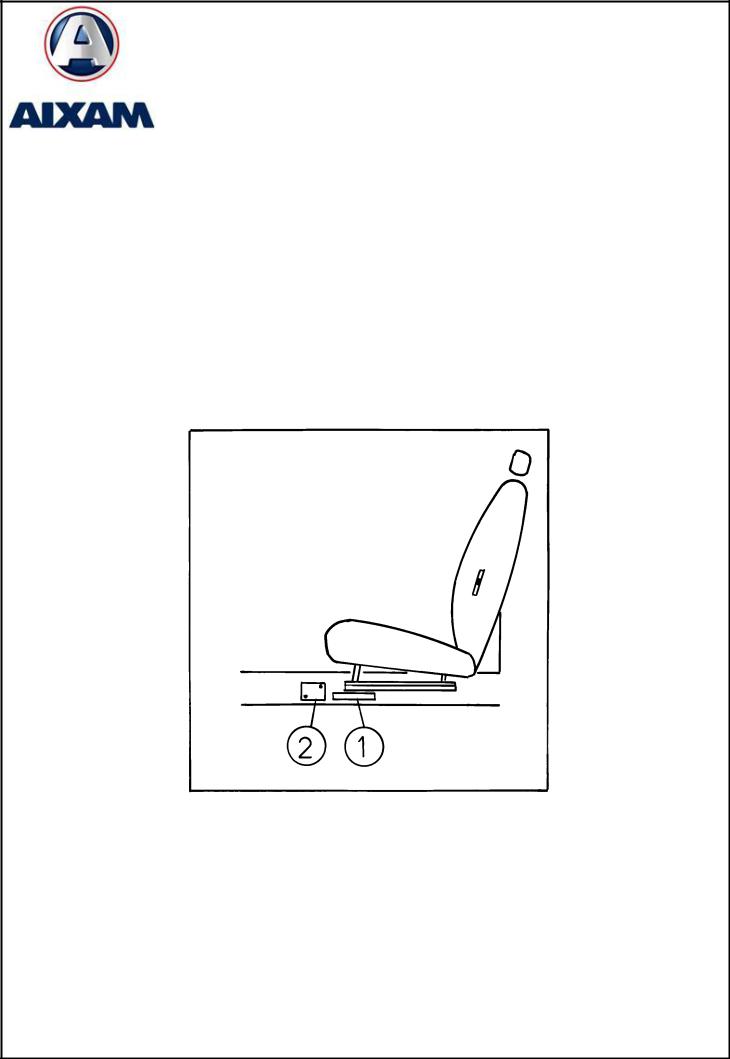
VEHICLE IDENTIFICATION
1-SERIAL NUMBER COLD PUNCH
The serial number is punched on the right-hand cross-member, inner side of the car, under the right-hand seat slider.
2-MANUFACTURER PLATE
The manufacturer plate is riveted to the right-hand stringer on the inner side of the car, next to the engraved serial number.
|
REPAIR MANUAL |
0 |
|
|
|
|
TIGHTENING TORQUES |
|
|
|
|
|
|
|
FUNCTION |
DESIGNATION |
SCREW |
COEF |
Torque in Nm |
||
Mini |
Maxi |
|||||
|
|
|
|
|||
|
Column tensioner |
M8*20 |
2 |
18,4 |
27,6 |
|
|
(upper screw) |
|||||
|
|
|
|
|
||
|
Column tensioner |
M8*35 |
2 |
18,4 |
27,6 |
|
STEERING |
(lower screw) |
|||||
|
|
|
|
|||
Flector column |
M8*20+nylstop |
2 |
18,4 |
27,6 |
||
Steering column |
nylstop M8 |
3 |
18,4 |
27,6 |
||
Steering joint (cardan) |
M8*35+nylstop |
1 |
18,4 |
27,6 |
||
|
Steering rack |
M10*60 |
2 |
36 |
54 |
|
|
Tie rod |
Nylstop M10*1,25 |
2 |
32 |
48 |
|
|
Steering wheel |
M12 torx |
1 |
40 |
60 |
|
BRAKES |
Handbrake |
M8*20 |
2 |
18,4 |
27,6 |
|
Master Cylinder |
M8*25+nylstop |
2 |
18,4 |
27,6 |
||
Banjo bolt limiter |
Thin thread banjo bolt |
4 |
20 |
30 |
||
Brake pedal |
M 6 x 16 |
1 |
8,8 |
13,2 |
||
|
||||||
SEATS/BELT |
Safety belt (upper screw) |
7/16' 20 UNF |
2 |
25 |
40 |
|
Safety belt (lower screw) |
7/16' 20 UNF |
2 |
25 |
40 |
||
Seat belt retractor |
7/16' 20 UNF |
2 |
25 |
40 |
||
Belt buckle |
7/16' 20 UNF |
2 |
25 |
40 |
||
Seats front sliders |
M6*30 |
8 |
8,8 |
13,2 |
||
|
||||||
|
Front wheel hub nut |
Nylstop M16*1,5 |
2 |
140 |
160 |
|
AXLE |
Front suspension triangles |
M10*50+Nylstop |
4 |
38 |
54 |
|
Front suspension ball joints |
Nylstop M12*1,25 |
2 |
40 |
60 |
||
t shock absorbers (upper sc |
Nylstop M10*1,00 |
2 |
16 |
24 |
||
& REAR |
||||||
t shock absorbers (lower sc |
Nylstop M12 |
2 |
36 |
54 |
||
Rear wheel hub axle |
M12*180+Nylstop |
2 |
64 |
96 |
||
FRONT |
r shock absorber (upper scr |
M10*65+Nylstop |
2 |
38 |
54 |
|
Rear suspension arm |
M10*65+nilstop |
4 |
38 |
54 |
||
Front wheel |
M10*1,25 |
16 |
40 |
60 |
||
|
||||||
|
Rear wheel |
M10*1,25 |
16 |
40 |
60 |
|
TRANSMISSION |
Receiver inverter |
Spiralock nut M12 |
1 |
90 |
110 |
|

|
REPAIR MANUAL |
1 |
|
|
|
|
KUBOTA Z402 and Z602 engines |
|
|
|
|
|
|
|
|
|
INDEX |
KUBOTA Z402 and Z602 engines: |
|
|
|
Cooling system .................................................................................................... |
2 |
|
Lubrication system ............................................................................................... |
3 |
|
Injection system ................................................................................................... |
4 to 7 |
|
Tightening torques Z402 ...................................................................................... |
8 |
|
Tightening torques Z602 ...................................................................................... |
9 |
|
Repair .................................................................................................................. |
10 to 12 |
LOMBARDINI 523 MPI engine |
|
|
|
Cooling system .................................................................................................... |
13 |
|
Lubrication system ............................................................................................... |
14 |
|
Injection system ................................................................................................... |
15 |
|
Tightening torques ............................................................................................... |
16, 17 |
|
Repair .................................................................................................................. |
18 |
|
REPAIR MANUAL |
|
|
|
1 |
|
KUBOTA Z402 and Z602 engines |
|
|
|
|
|
|
|
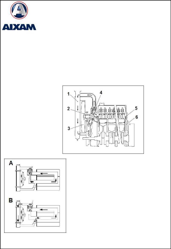
Cooling system
Forced circulation cooling system with water pump. Temperature regulation is ensured by a thermostat fastened on the upper water manifold of the cylinder head.
The thermostat is controlled as defined below:
Start of thermostat valve opening |
69.5 to 72.5 °C |
Full opening of the thermostat valve |
85 °C |
The water pump is centrifugal and driven by the accessory belt.
1 : Radiator
2 : Water pump
3 : Fan
4 : Thermostat
5 : Cylinder head
6 : Engine block
A:Thermostat closed, short circulation enhancing engine temperature build-up
B:Thermostat open, long circulation to cool the engine.
Quantity of coolant: 2 litres
|
REPAIR MANUAL |
|
|
|
1 |
|
KUBOTA Z402 and Z602 engines |
|
|
|
|
|
|
|
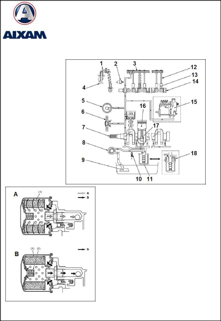
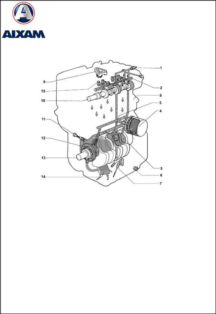
Lubrication system
1 : Rocker
2 : Pressure switch
3 : Rocker ramp
4 : Valve
5 : NA on 400
6 : Distribution
7 : Crankshaft
8 : Oil pump
9 : Strainer
10 : Overpressure valve
11 : Oil filter
12 : Push rod
13 : Indexed push rod
14 : Camshaft
15 : Injection pump
16 : Piston
A: Filter OK
B: Clogged filter
Quantity of Z402 oil: 1.80 litres Quantity of Z602 oil: 2.50 litres

|
REPAIR MANUAL |
|
|
|
1 |
|
KUBOTA Z402 and Z602 engines |
|
|
|
|
|
|
|
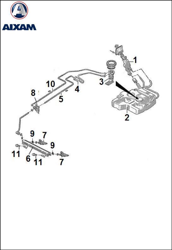
Injection system
The injection pump delivers the quantity of fuel required to meet the driver's demand.
The injection pump preserves the engine of any overspeeding and ensures idle running stability. The injection pump controls engine stopping when requested.
It is divided into four separate parts:
-Low pressure
-High pressure
-Regulation
-Control
The low pressure circuit comprises the:
1.Fuel tank
2.Strainer
3.Fuel pre-filter
4.Supply pump
5.Main filter
The high pressure circuit comprises the:
6.Injection pump
7.Injectors
|
REPAIR MANUAL |
|
|
|
1 |
|
KUBOTA Z402 and Z602 engines |
|
|
|
|
|
|
|
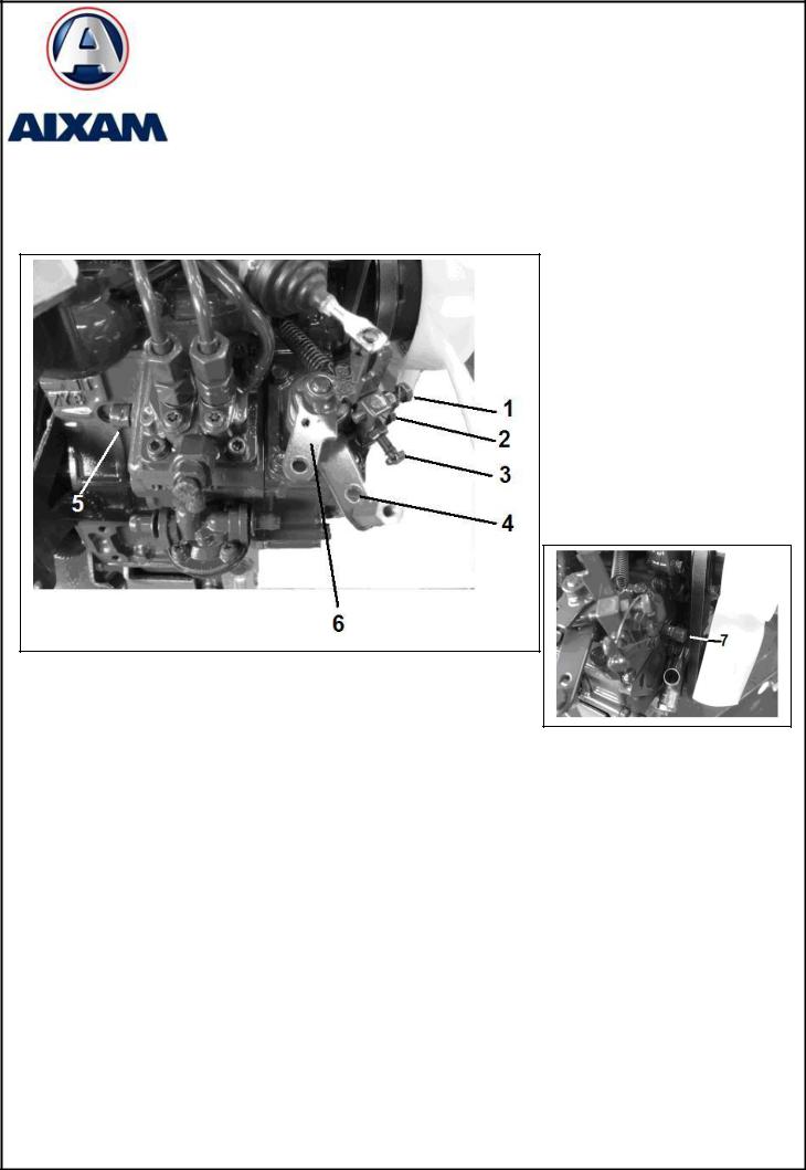
Adjusting and tuning
The basic adjustments are located on the injection pump or injection pump housing.
1. Engine Stop
2. Min acc. stop
3. Max acc. stop
4. Acceleration lever
5. Idle adjust screw
6. Engine stop lever
7. Max load adjust screw
Idle adjust
Idle adjustment is made from screw 5.
However, idle speed must be reduced by 50 rpm by the min acceleration stop (2) and compensated with the idle adjust screw (5) to avoid untimely engine stalling.
Load adjust
Max load adjustment is done with screw 7.
However, modifying this adjustment is not authorized. Adjustment of this screw is highly sensitive and may cause excessive smoke or lack of power. In case of problem linked with this adjustment, and once all other causes have been eliminated, call after-sales.
|
REPAIR MANUAL |
|
|
|
1 |
|
KUBOTA Z402 and Z602 engines |
|
|
|
|
|
|
|
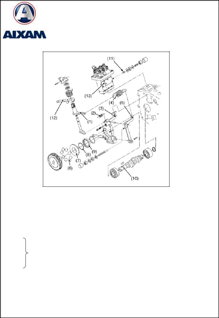
Regulation principle
1.Accelerator lever
2.Starting spring
3.Regulation lever
4.Regulation spring
5.Intermediate regulation lever
6.–
7.–
Centrifugal regulator
8.–
9.–
10.Pump camshaft
11.Idle spring
12.Accelerator control
13.Flow control rod

|
REPAIR MANUAL |
|
|
|
1 |
|
KUBOTA Z402 and Z602 engines |
|
|
|
|
|
|
|
Upon starting:
Spring 2 drives lever 3 to the maximum flow position, the control rod is in the maximum flow position. When the engine starts, the centrifugal force applied to the regulator is stronger that the cold start spring, hence lever 3 is pushed to the minimum flow position, and the control rod pushes the idle spring 11.
At idle:
Centrifugal force applied to the regulator is sufficient to maintain lever 3 and the control rod on idle spring 11. The spring 11 ensures idle running stability.
At full load:
Upon acceleration request, lever 1 applies a tension on spring 2, which drives lever 5. Lever 5 drives lever 3, and moves the flow control rod in max load position. When speed reaches the maximum, the centrifugal force applied to the regulator becomes higher than that applied by spring 4, the control rod moves to a flow reduction.
Upon engine stop:
The engine stop lever pushes lever 3 in min flow position, the force applied to the lever is important enough to completely compact the idle spring, hence cutting engine injection.

|
REPAIR MANUAL |
|
|
|
1 |
|
KUBOTA Z402 and Z602 engines |
|
|
|
|
|
|
|
TIGHTENING TORQUES Z402
The screws, bolts and nuts must be tightened at the torque specified using a torque wrench.
Several screws, bolts and nuts, such as those on the cylinder head, must be tightened in a specific sequence and torque.
1.Tightening torques for screws, bolts and nuts for particular use
For screws, bolts and nuts marked « * » in the table, smear the threading and seats with motor oil before tightening.
The letter « M » of dimension x pitch means that the dimension of the screw, bolt or nut relies on the metric system.
The dimension is the nominal outer diameter of the threadings in mm.
The pitch is the nominal distance in mm between two threads.
Element |
Dimension x pitch |
N-m |
Kgf-m |
* Cylinder head cover nuts |
M6 x 1.0 |
3.9 to 5.9 |
0.4 to 0.6 |
* Cylinder head screws |
M8 x 1.25 |
37.2 to 42.1 |
3.8 to 4.3 |
* Main bearing fastening screw 1 |
M6 x 1.0 |
12.7 to 15.7 |
1.3 to 1.6 |
* Main bearing fastening screw 1 (flywheel side) |
M8 x 1.25 |
23.5 to 27.4 |
2.4 to 2.8 |
* Main bearing fastening screw 2 |
M7 x 1.0 |
26.5 to 30.4 |
2.7 to 3.1 |
* Flywheel screws |
M10 x 1.25 |
53.9 to 58.8 |
5.5 to 6 |
* Piston rod screws |
M7 x 0.75 |
26.5 to 30.4 |
2.7 to 3.1 |
* Rocker arm support nuts |
M6 x 1.0 |
9.8 to 11.3 |
1.00 to 1.15 |
* Gear shaft screw |
M6 x 1.0 |
9.8 to 11.3 |
1.00 to 1.15 |
* Crankshaft end bolt |
M12 x 1.5 |
117.6 to 127.4 |
12.0 to 13.0 |
* Bearing box cover screws |
M6 x 1.0 |
9.8 to 11.3 |
1.00 to 1.15 |
Glow plugs |
M8 x 1.0 |
7.8 to 14.7 |
0.8 to 1.5 |
Injector holder assembly |
M20 x 1.5 |
49.0 to 68.6 |
5.0 to 7.0 |
Oil pressure switch tapered screw |
PT 1/8 |
14.7 to 19.6 |
1.5 to 2.0 |
Injection duct fastening nuts |
M12 x 1.5 |
24.5 to 34.3 |
2.5 to 3.5 |
Overflow pipe assembly fastening nuts |
M12 x 1.5 |
19.6 to 24.5 |
2.0 to 2.5 |
Starter nut B terminal fitting nut |
M8 |
8.8 to 11.8 |
0.9 to 1.2 |
2. Tightening torques for screws, bolts and nuts for general use
When tightening torque values are not specified, tighten the screws, bolts, and nuts at the values specified in the following table.
|
Grade |
Standard screws and |
Special screws and |
|||
|
bolts 4 |
bolts 7 |
||||
|
|
|||||
|
|
|
|
|
|
|
|
Unit |
N-m |
Kgf-m |
N-m |
Kgf-m |
|
|
M6 |
7.9 to 9.3 |
0.80 to 0.95 |
9.8 to 11.3 |
1.00 to 1.15 |
|
Nominal diameter |
M8 |
17.7 to 20.6 |
1.8 to 2.1 |
23.5 to 27.5 |
2.4 to 2.8 |
|
M10 |
39.2 to 45.1 |
4.0 to 4.6 |
48.1 to 55.9 |
4.9 to 5.7 |
||
|
||||||
|
M12 |
62.8 to 72.6 |
6.4 to 7.4 |
77.5 to 90.2 |
7.9 to 9.2 |
|
The material grade is indicated by numbers engraved on the heads of screws and bolts. Always check the numbers indicated below before tightening.
Number |
|
engraved |
Material grade of the screw or bolt |
None or 4 |
SS41, S20C screw and bolt |
|
S43C, S48C special screw and bolt |
7 |
(refined) |

|
REPAIR MANUAL |
|
|
|
1 |
|
KUBOTA Z402 and Z602 engines |
|
|
|
|
|
|
|
TIGHTENING TORQUES Z602
Tightening torques for screws, bolts and nuts for particular use
For screws, bolts and nuts marked « * » in the table, smear the threading and seats with motor oil before tightening.
The letter « M » of dimension x pitch means that the dimension of the screw, bolt or nut relies on the metric system.
The dimension is the nominal outer diameter of the threadings in mm.
The pitch is the nominal distance in mm between two threads.
|
Dimension x |
|
|
|
|
Elements |
pitch |
N-m |
Kgf-m |
Pounds-feet |
|
* Rocker cover bolts |
M6 x |
1 |
6.86 to 11.3 |
0.7 to 1.15 |
5.1 to 8.3 |
Injection duct fastening nut |
M12 x 1.5 |
24.5 to 34.3 |
2.5 to 3.5 |
18.1 to 25.3 |
|
Overflow duct fastening nut |
M12 x 1.5 |
19.6 to 24.5 |
2.0 to 2.5 |
14.5 to 18.1 |
|
Injector unit |
M20 x |
15 |
49.0 to 68.6 |
5.0 to 7.0 |
36.2 to 50.6 |
Glow plug |
M8 x |
1 |
7.8 to 14.7 |
0.8 to 1.5 |
5.8 to 10.8 |
* Rocker ramp nut |
M6 x |
1 |
9.8 to 11.3 |
1.00 to 1.15 |
7.2 to 8.3 |
* Cylinder head bolt |
M8 x 1.25 |
37.3 to 42.2 |
3.8 to 4.3 |
27.5 to 31.1 |
|
|
|
|
117.7 to |
|
|
* Fan drive pulley screw |
M12 x 1.5 |
127.5 |
12.0 to 13.0 |
86.8 to 94.0 |
|
* Intermediate gear shaft fastening screws |
M6 x |
1 |
9.8 to 11.3 |
1.00 to 1.15 |
7.2 to 8.3 |
Injection pump fastening screws |
M8 x 1.25 |
17.7 to 21.6 |
1.80 to 2.20 |
13.0 to 15.9 |
|
* Connecting rod head bolt |
M7 x 0.75 |
26.5 to 30.4 |
2.7 to 3.1 |
19.5 to 22.4 |
|
* Flywheel bolt |
M10 x 1.25 |
53.9 to 58.8 |
5.5 to 6.0 |
39.8 to 43.4 |
|
Main bearing cap cover fastening bolt |
M6 x |
1 |
9.8 to 11.3 |
1.00 to 1.15 |
7.2 to 8.3 |
* Main crankshaft bearing bolt 2 |
M7 x |
1 |
26.5 to 30.4 |
2.7 to 3.1 |
19.5 to 22.4 |
* Main crankshaft bearing bolt 1 |
M6 x |
1 |
12.7 to 15.7 |
1.3 to 1.6 |
9.4 to 11.6 |
Oil pressure switch |
PT 1/8 |
14.7 to 19.6 |
1.5 to 2.0 |
10.8 to 14.5 |
|
Injector nose support |
|
|
34.3 to 39.2 |
3.5 to 4.0 |
25.3 to 28.9 |
Starter B terminal fastening nut (electromagnetic drive |
M8 |
|
7.8 to 9.8 |
0.8 to 1.0 |
5.8 to 7.2 |
type) |
|
||||
|
|
|
|
|
|
Starter B terminal fastening nut (planetary gear |
M8 |
|
5.9 to 11.8 |
0.6 to 1.2 |
4.3 to 8.7 |
reduction type) |
|
||||
|
|
|
|
|
|
Generator pulley nut |
M10 x 1.25 |
39.2 to 44.1 |
4.0 to 4.5 |
28.9 to 32.5 |
|
Alternator pulley nut |
|
|
58.3 to 78.9 |
5.95 to 8.05 |
43.0 to 58.2 |
Drain plug with copper gasket |
M12 x 1.25 |
32.4 to 37.3 |
3.3 to 3.8 |
23.9 to 27.5 |
|
Drain plug with copper gasket |
M22 x 1.5 |
63.7 to 73.5 |
6.5 to 7.5 |
47.0 to 54.2 |
|
Drain plug with rubber coating gasket |
M22 x 1.5 |
44.1 to 53.9 |
4.5 to 5.5 |
32.5 to 39.8 |
|
|
REPAIR MANUAL |
|
|
|
1 |
|
KUBOTA Z402 and Z602 engines |
|
|
|
|
|
|
|
|
REPAIR |
|
Anomaly |
Possible cause |
Solution |
|
|
No fuel |
Fill up |
|
|
|
|
|
|
Air in the supply circuit |
Purge the air |
|
|
|
|
|
|
Water in the supply circuit |
Change the fuel and repair or change the |
|
|
supply system |
||
|
|
||
|
|
|
|
|
Clogged supply duct |
Clean |
|
|
|
|
|
|
Clogged fuel filter |
Clean or change |
|
|
|
|
|
|
Fuel or oil viscosity too high |
Use the fuel or motor oil specified |
|
|
|
|
|
|
Low hexadecane index fuel |
Use the fuel specified |
|
|
|
|
|
|
Fuel leak due to bad tightening of a |
Tighten the nut |
|
|
fastening nut on the injection duct |
||
|
|
||
|
|
|
|
|
Bad injection timing |
Adjust |
|
The engine does |
|
|
|
Camshaft wear |
Change |
||
not start |
|
|
|
Clogged injector |
Clean |
||
|
|||
|
|
|
|
|
Bad operation of the injection pump |
Repair or change |
|
|
|
|
|
|
Seized crankshaft, camshaft, piston, |
Repair or change |
|
|
cylinder jacket or main bearing |
||
|
|
||
|
|
|
|
|
|
Change the cylinder head gasket, tighten |
|
|
No compression in the cylinder |
the cylinder head screw, change the glow |
|
|
|
plug and injector holder |
|
|
|
|
|
|
Bad timing |
Readjust or change the timing gear |
|
|
|
|
|
|
Worn piston rings and jacket |
Change |
|
|
|
|
|
|
Excess play in timing |
Adjust |
|
|
|
|
|
|
Battery discharged |
Charge |
|
|
|
|
|
|
Faulty starter operation |
Repair or change |
|
The starter is |
|
|
|
|
|
||
inoperative |
Faulty key switch |
Repair or change |
|
|
|
|
|
|
Wiring disconnected |
Connect |
|
|
|
|

|
REPAIR MANUAL |
|
|
|
1 |
|
KUBOTA Z402 and Z602 engines |
|
|
|
|
|
|
|
|
REPAIR (cont’d) |
|
Anomaly |
Possible cause |
Solution |
|
|
Clogged or dirty fuel filter |
Clean or change |
|
|
|
|
|
|
Clogged air filter |
Clean or change |
|
|
|
|
|
|
Fuel leak due to bad tightening of a |
Retighten the nut |
|
|
fastening nut on the injector duct |
||
|
|
||
The engine does |
|
|
|
|
|
||
not run regularly |
Bad operation of the injection pump |
Repair or change |
|
|
|
|
|
|
Bad injector opening pressure |
Adjust |
|
|
|
|
|
|
Stuck or clogged injector |
Repair or change |
|
|
Faulty regulator operation |
Repair |
|
|
|
|
|
|
Excess motor oil |
Reduce to level specified |
|
|
|
|
|
|
Wear or sticking of a piston ring and a |
Repair or change |
|
|
jacket |
||
|
|
||
|
|
|
|
|
Bad injection timing |
Adjust |
|
|
|
|
|
Exhaust gases |
Bad compression |
Adjust neutral spaces |
|
black, or dark grey |
Overload |
Reduce the load |
|
|
|
|
|
|
Bad quality fuel |
Use the fuel specified |
|
|
|
|
|
|
Clogged fuel filter |
Clean or change |
|
|
|
|
|
|
Clogged air filter |
Clean or change |
|
|
|
|
|
|
Faulty injector |
Repair or change the injector |
|
|
|
|
|
|
Bad injection timing |
Adjust |
|
|
|
|
|
|
The engine moving parts seem to be seized |
Repair or change |
|
|
|
|
|
Insufficient power |
Irregular fuel injection |
Repair or change the injection pump |
|
|
|
|
|
|
Faulty injector |
Repair or change the injector |
|
|
|
|
|
|
|
Change the cylinder head gasket, tighten |
|
|
Lack of compression |
the cylinder head screw, the glow plug and |
|
|
|
injector holder |
|
|
|
|
|
|
The cutting gap is set in the same direction |
Modify the location of the cutting gap |
|
|
for all piston rings |
|
|
|
Worn or stuck oil control ring |
Change |
|
|
|
|
|
|
Worn piston ring groove |
Change the piston |
|
Excessive oil |
Worn valve stem and guide |
Change |
|
consumption |
|||
|
|
||
|
|
|
|
|
Worn crankshaft main bearings or trunnion |
Change |
|
|
bearings |
||
|
|
||
|
|
|
|
|
Oil leaked caused by a faulty lining or |
Change |
|
|
sealing |
||
|
|
||
|
|
|

|
REPAIR MANUAL |
|
|
|
1 |
|
KUBOTA Z402 and Z602 engines |
|
|
|
|
|
|
|
|
REPAIR (cont’d) |
|
Anomaly |
Possible cause |
Solution |
|
Fuel mixed with |
Worn injection pump plunger |
Change the pump element or pump |
|
|
|
||
lubrication oil |
Faulty injector |
Repair or change the injector |
|
|
Injection pump |
Change |
|
Water mixed with |
Faulty cylinder head gasket |
Change |
|
lubrication oil |
Flaky casing or cylinder head |
Change |
|
|
Low motor oil |
Top up |
|
|
Clogged strainer |
Clean |
|
|
Discharge valve stuck by dirt |
Clean |
|
|
Fatigue or broken discharge valve spring |
Change |
|
|
|
|
|
|
Too much running gap of a crankshaft |
Change |
|
|
bearing |
||
Low oil pressure |
|
||
|
|
||
Too much running gap of a connecting |
Change |
||
|
|||
|
rod head bearing |
||
|
|
||
|
|
|
|
|
Too much running gap of a push rod |
Change |
|
|
bushing |
||
|
|
||
|
|
|
|
|
Clogged oil passage |
Clean |
|
|
Inappropriate type of oil |
Use the type of oil specified |
|
|
Faulty oil pump |
Repair or change |
|
High oil pressure |
Inappropriate type of oil |
Use the type of oil specified |
|
Faulty discharge valve |
Change |
||
|
|||
|
Low motor oil |
Top up |
|
|
Fan belt broken or loose |
Change or adjust |
|
|
|
|
|
|
Low coolant |
Top up |
|
|
Radiator honeycomb or fins clogged |
Clean |
|
|
|
|
|
Overheating engine |
Corroded radiator interior |
Clean or change |
|
Corroded coolant circuit |
Clean or change |
||
|
|||
|
|
|
|
|
Faulty radiator plug |
Change |
|
|
Run with overload |
Reduce the load |
|
|
Faulty cylinder head gasket |
Change |
|
|
Bad injection timing |
Adjust |
|
|
Inappropriate fuel type |
Use the fuel specified |
|
|
Low electrolyte |
Fill distilled water and charge the battery |
|
|
|
|
|
Battery discharges |
Slipping fan belt |
Adjust belt tension or change it |
|
|
|
||
too fast |
Wiring disconnected |
Reconnect |
|
|
Rectifier disconnected |
Change |
|
|
Faulty fan generator |
Change |
|
|
Faulty battery |
Change |
|
|
|
|

|
|
REPAIR MANUAL |
|
|
|
|
|
1 |
|
|
|
LOMBARDINI 523 MPI engine |
||
|
|
|
|
|
|
|
|
|
|
|
|
COOLING SYSTEM |
|
|
|
|
|
|
|
|
|
|
|
|
3.Thermostatic valve
4.Cylinder block
5.Coolant temperature indicator thermostat
6.Circulation pump
7.Ventilation helix
8.Radiator
Quantity of coolant: 2 litres
|
|
REPAIR MANUAL |
|
|
|
|
|
|
1 |
|
|
LOMBARDINI 523 MPI engine |
||
|
|
|
||
|
|
|
|
|
|
|
LUBRICATION SYSTEM |
|
|
|
|
|
|
|
|
|
|
|
|
1.Pressure switch
2.Rocker stud
3.Connecting rod head stud
4.Oil filter cartridge
5.Main bearing stud
6.Oil change plug
7.Oil gauge
8.Vent
9.Oil fill plug
10.Camshaft
11.Oil pressure adjust valve
12.Oil pump
13.Crankshaft
14.Oil suction filter
15.Hydraulic push rod
Oil quantity (with filter) = 1.3 litres
Oil quantity (without filter) = 1.2 litres
|
|
REPAIR MANUAL |
|
|
|
|
|
1 |
|
|
|
LOMBARDINI 523 MPI engine |
||
|
|
|
|
|
|
|
|
|
|
|
|
INJECTION SYSTEM |
|
|
|
|
|
|
|
|
|
|
|
|
1.Filling pipe
2.Tank
3.Fuel pump / gauge plant
4.Filter
5.Supply duct
6.Injector supply pipe
7.Injector
8.Pressure regulator
9.Injector holding spring
10.Pressure regulator return pipe
11.Supply pipe fastening screw
|
REPAIR MANUAL |
|
|
|
1 |
|
LOMBARDINI 523 MPI engine |
|
|
|
|
|
|
|
TIGHTENING TORQUES
The following tables indicate the tightening torques for standard screws and main components. The tightening torques are also indicated with the tightening methods and sequences, in the indications of fitting of components and/or the plant.
TABLE OF TIGHTENING TORQUES OF STANDARD SCREWS (wide pitch)
|
|
|
|
Resistance class (R) |
|
|
|
||
Grade / |
|
|
|
|
|
|
|
|
|
|
|
|
|
|
|
|
|
|
|
Dimensions |
|
|
|
|
|
|
|
|
|
|
|
|
|
|
|
|
|
|
|
Diameter |
R>400N/mm² |
R>500N/mm² |
R>600N/mm² |
R>800N/mm² |
R>1000N/mm² |
R>1200N/mm² |
|||
Nm |
Nm |
Nm |
|
Nm |
Nm |
Nm |
Nm |
Nm |
|
|
|
||||||||
M3 |
0,5 |
0,7 |
0,6 |
|
0,9 |
1 |
1,4 |
1,9 |
2,3 |
M4 |
1,1 |
1,5 |
1,4 |
|
1,8 |
2,2 |
2,9 |
4,1 |
4,9 |
M5 |
2,3 |
3 |
2,8 |
|
3,8 |
4,5 |
6 |
8,5 |
10 |
M6 |
3,8 |
5 |
4,7 |
|
6,3 |
7,5 |
10 |
14 |
17 |
M8 |
9,4 |
13 |
12 |
|
16 |
19 |
25 |
35 |
41 |
M10 |
18 |
25 |
23 |
|
31 |
37 |
49 |
69 |
83 |
M12 |
32 |
43 |
40 |
|
54 |
65 |
86 |
120 |
145 |
M14 |
51 |
68 |
63 |
|
84 |
101 |
135 |
190 |
230 |
M16 |
79 |
105 |
98 |
|
131 |
158 |
210 |
295 |
355 |
M18 |
109 |
145 |
135 |
|
181 |
218 |
290 |
405 |
485 |
M20 |
154 |
205 |
193 |
|
256 |
308 |
410 |
580 |
690 |
M22 |
206 |
275 |
260 |
|
344 |
413 |
550 |
780 |
930 |
M24 |
266 |
355 |
333 |
|
444 |
533 |
710 |
1000 |
1200 |
M27 |
394 |
525 |
500 |
|
656 |
788 |
1050 |
1500 |
1800 |
M30 |
544 |
725 |
680 |
|
906 |
1088 |
1450 |
2000 |
2400 |
TABLE OF TIGHTENING TORQUES OF STANDARD SCREWS (thin pitch) |
|
|
|||||||
Diameter |
R>400N/mm² |
R>500N/mm² |
R>600N/mm² |
R>800N/mm² |
R>1000N/mm² |
R>1200N/mm² |
|||
Nm |
Nm |
Nm |
|
Nm |
Nm |
Nm |
Nm |
Nm |
|
|
|
||||||||
M 8x1 |
10 |
14 |
23 |
|
17 |
20 |
27 |
38 |
45 |
M 10x1 |
21 |
28 |
26 |
|
35 |
42 |
56 |
79 |
95 |
M 10x1.25 |
20 |
26 |
24 |
|
33 |
39 |
52 |
73 |
88 |
M 12x1.25 |
36 |
48 |
45 |
|
59 |
71 |
95 |
135 |
160 |
M 12x1.5 |
38 |
45 |
42 |
|
56 |
68 |
90 |
125 |
150 |
M 14x1.5 |
56 |
75 |
70 |
|
94 |
113 |
150 |
210 |
250 |
M 16x1.5 |
84 |
113 |
105 |
|
141 |
169 |
225 |
315 |
380 |
M 18x1.5 |
122 |
163 |
153 |
|
203 |
244 |
325 |
460 |
550 |
M 18x2 |
117 |
157 |
147 |
|
196 |
235 |
313 |
440 |
530 |
M 20x1,5 |
173 |
230 |
213 |
|
288 |
345 |
460 |
640 |
770 |
M 20x2 |
164 |
218 |
204 |
|
273 |
327 |
436 |
615 |
740 |
M 22x1.5 |
229 |
305 |
287 |
|
381 |
458 |
610 |
860 |
1050 |
M 24x2 |
293 |
390 |
367 |
|
488 |
585 |
780 |
1100 |
1300 |
M 27x2 |
431 |
575 |
533 |
|
719 |
863 |
1150 |
1600 |
1950 |
M 30x2 |
600 |
800 |
750 |
|
1000 |
1200 |
1600 |
2250 |
2700 |

|
REPAIR MANUAL |
|
|
|
1 |
|
LOMBARDINI 523 MPI engine |
|
|
|
|
|
|
|
|
TIGHTENING TORQUES |
|
Table of tightening torques for the main components
|
DIAMETER x PITCH |
|
DESCRIPTION |
(mm) |
TIGHTENING TORQUE (Nm) |
Connecting rod |
8x1 |
40 |
Rocker cover |
6x1 |
9 |
Casing (crankshaft fastening screws) |
M 10 |
50 |
Casing (one-piece fastening screws) |
M 6 |
10 |
Timing belt roller nut |
M 10 |
40 |
Rocker stud holder nut |
10x1.5 |
40 |
Oil sealing ring flange screw (flywheel side) |
M 6 |
12 |
Crankshaft pulley screw (timing side) |
16x1.5 sin |
180(1)* |
Camshaft pulley screw |
10x1.25 |
50 |
Timing shaft bearing panel |
M 6x1 |
10 |
Camshaft holder flange |
M 6x1 |
10 |
Small closing flange |
M 6x1 |
10 |
Suction manifold fastening screw |
M 6x1 |
10 |
Revolution sensor holder fastening screw |
M 6x1 |
10 |
Revolution sensor fastening screw |
M 8x1.25 |
10 |
Oil pressure switch |
|
25 |
Oil plug |
12x1.5 |
40 |
Engine cylinder head screw |
12x1.5 |
(2)* |
Flywheel screw |
|
80 |
Coolant thermostat |
10x1.5 |
30 |
(1)* Lubricate the lower part of the screw and pulley centre with some « Molysilp » (2)* For more precise information see « Fitting the cylinder head »

|
REPAIR MANUAL |
|
|
|
1 |
|
LOMBARDINI 523 MPI engine |
|
|
|
|
|
|
|
REPAIR
Table of probable anomalies according to symptoms
The engine does not start |
Difficult starting with cold engine |
Difficult starting with warm engine |
Overheating motor |
Unstable idle running |
Idle running too high |
Idle running too low |
The engine stops at idle |
The engine stops sometimes |
Jolting upon reacceleration |
Jolting once idle running stabilized |
Jolting acceleration |
Low performance |
High consumption |
Noise (beating or rattling) |
Crackling |
Blue smoke |
White smoke |
Damaged catalyst |
|
Air supply
 Air filter
Leak on the manifold
Butterfly body
Fuel supply
The pressure regulator stays open
The pressure regulator stays closed
Clogged pipes
No pump flow
Running injector
Poor fuel quality
Ignition |
Coil (coil short-circuit) |
Faulty spark plug cable |
Worn spark plugs |
Spark plugs too cold |
Spark plugs too warm |
Exhaust |
 Leaks on the manifold
Oxygen probe
Engine and mechanical
 Leaky valve
 Valve stuck
 Bad valve sealing guide
 Jacket / piston wear
Embedded combustion chamber
Insufficient cooling


 Damaged cylinder head gasket
Damaged revolution sensor phonic wheel
Faulty hydraulic push rods
 Oil level too high
Electrical equipment
Low contact on fuel pump connector |
Burnt fuse |
Faulty relay |
Faulty engine wiring |
Faulty battery elements |
Battery terminals sulphated |

|
REPAIR MANUAL |
3 |
|
|
|
|
Reverser bridge |
|
|
|
|
|
|
|
|
INDEX |
|
|
Reverser axle....................................................................................................... |
2 |
|
Transmission ....................................................................................................... |
3 |
Regulator set VSP 2000 LP2 version 2................................................................ |
4 to 23 |
|
 Loading...