


TS-UC15 U(W)
SERVICE MANUAL
ACTIVE SPEAKER SYSTEM
S/M Code No. 09-994-328-2N1
DATA

SPECIFICATIONS
Power supply |
120 V AC, 60 Hz |
Input terminals/sensitivity |
AUX IN: 500 mV/10 kilo ohms, |
Power consumption |
20 W |
|
stereo minijack (1) |
Speakers |
77 mm full range antimagnetic |
|
USB: USB Rev.1.0 standard |
|
type satellite speakers/6 ohms (2) |
Output terminals |
SPEAKER: To satellite speakers |
|
100 mm antimagnetic type |
|
(L. R), 6 ohms |
|
subwoofer (1) |
Dimensions (w/h/d) |
Satellite speakers |
Power output |
<Satellite speakers> |
|
99 * 128 * 108 mm |
|
FTC RULE |
|
(4 * 5 1/5 * 4 3/8 in) |
|
3 watts per channel, Min. RMS at |
|
Subwoofer |
|
6 ohms, from 120 Hz to 15,000 |
|
168 * 262 * 251 mm |
|
Hz, with no more than 1% total |
|
(6 5/8 * 10 3/8 * 10 in) |
|
harmonic distortion |
Weight |
Satellite speaker. 0.38 kg (13 oz) |
|
4 W+4 W |
|
* 2 |
|
(6 ohms, T.H.D. 10% at 1 kHz) |
|
Subwoofer: 3.1 kg (6 lbs 13 oz) |
|
3 W+3 W |
• Design and specifications are subject to change without |
|
|
(6 ohms, T.H.D. 1% at 1 kHz) |
||
|
|
||
|
<Subwoofer> |
notice. |
|
|
FTC RULE |
|
|
|
8 watts, Min. RMS at 4 ohms, |
|
|
|
form 50 Hz to 120 Hz, with no |
|
|
|
more than 1% total harmonic |
|
|
|
distortion |
|
|
|
12 W |
|
|
|
(4 ohms, T.H.D. 10% at 70 Hz) |
|
|
|
8 W |
|
|
|
(4 ohms, T.H.D. 1% at 70 Hz) |
|
|
Frequency response |
<Satellite speakers> |
|
|
|
250 Hz to 20,000 Hz |
|
|
|
<Subwoofer> |
|
|
|
40 Hz to 250 Hz |
|
|
ACCESSORIES/PACKAGE LIST
REF. NO |
PART NO. |
KANRI |
DESCRIPTION |
|
|
|
|
NO. |
|
1 |
8Z-YP6-901-010 |
IB,U(3L) |
|
|
2 |
8Z-YP6-608-010 |
CORD ASSY,USB 3M |
||
2 |
8Z-YP6-609-010 |
CORD ASSY,3.5ST-2M VW1 |
||
2
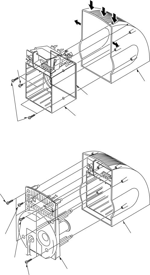
DISASSEMBLY INSTRUCTIONS
1)Remove the four screws (BVT2+3-20). (1)
2)Remove the screw (VFTT+3-6). (2)
3)CABI, INNER and CABI, FRONT are difficult to remove because they are coated with silicon. Therefore, remove the CABI, INNER by pressing the top panel of CABI, FRONT until it is distorted. (3)
2VFTT+3-6
1 BVT2+3-20
3
3
3
CABI, FRONT
Silicon coating area
CABI, INNER
1)Remove the six screws (BVT2+3-20). (1)
2)Remove the screw (BV2+3-8). (2)
3)Remove the two screws (BV2+3-10). (3)
4)Remove MOUNT CABI REAR ASSY from CABI, FRONT. (4)
1 BVT2+3-20
2 BVT2+3-8 |
CABI, FRONT |
3 BV2+3-10
MOUNT CABI REAR ASSY
1 BVT2+3-20
3

ELECTRICAL MAIN PARTS LIST
REF. NO |
PART NO. |
KANRI |
DESCRIPTION |
|
|
|
|
NO. |
|
IC |
|
|
|
|
|
87-001-629-110 |
IC,LA4630 |
|
|
|
87-A20-754-010 |
IC,BA4558N-DX |
||
|
8Z-YP5-607-010 |
IC,UDA1321T |
||
|
87-A21-195-080 |
IC,RE5RE33AA |
||
TRANSISTOR |
|
|
|
|
|
89-420-612-010 |
TR,2SD2061 (2W) |
||
|
89-318-155-080 |
TR,2SC1815 (0.4W) |
||
DIODE |
|
|
|
|
|
87-017-933-080 |
ZENER,MTZJ10D |
||
|
87-020-465-080 |
DIODE,1SS133 (110MA) |
||
|
87-070-178-090 |
DIODE,1N5402-BD54 |
||
MAIN C.B |
|
|
|
|
C1 |
87-018-131-080 |
CAP, CER 1000P-50V |
||
C2 |
87-018-131-080 |
CAP, CER 1000P-50V |
||
C5 |
87-010-405-080 |
CAP, ELECT 10-50V |
||
C6 |
87-010-405-080 |
CAP, ELECT 10-50V |
||
C7 |
87-010-404-080 |
CAP, ELECT 4.7-50V |
||
C8 |
87-010-404-080 |
CAP, ELECT 4.7-50V |
||
C9 |
87-010-401-080 |
CAP, ELECT 1-50V |
||
C10 |
87-010-401-080 |
CAP, ELECT 1-50V |
||
C11 |
87-018-132-080 |
CAP, CER 2200P-16V |
||
C12 |
87-018-132-080 |
CAP, CER 2200P-16V |
||
C14 |
87-010-404-080 |
CAP, ELECT 4.7-50V |
||
C15 |
87-010-404-080 |
CAP, ELECT 4.7-50V |
||
C16 |
87-010-235-080 |
CAP,E 470-16 SME |
||
C17 |
87-010-112-080 |
CAP, ELECT 100-16V |
||
C18 |
87-018-131-080 |
CAP, CER 1000P-50V |
||
C27 |
87-010-101-080 |
CAP, ELECT 220-16 |
||
C28 |
87-010-101-080 |
CAP, ELECT 220-16 |
||
C29 |
87-010-405-080 |
CAP, ELECT 10-50V |
||
C30 |
87-010-497-080 |
CAP,E 4.7-35 5L |
||
C31 |
87-010-490-080 |
CAP,E 0.1-50 |
||
C32 |
87-010-260-080 |
CAP, ELECT 47-25V |
||
C33 |
87-010-405-080 |
CAP, ELECT 10-50V |
||
C36 |
87-010-400-080 |
CAP, ELECT 0.47-50V |
||
C37 |
87-010-405-080 |
CAP, ELECT 10-50V |
||
C38 |
87-018-209-080 |
CAP, CER 0.1-50V |
||
C39 |
87-018-209-080 |
CAP, CER 0.1-50V |
||
C40 |
87-018-209-080 |
CAP, CER 0.1-50V |
||
C41 |
87-018-209-080 |
CAP, CER 0.1-50V |
||
C42 |
87-A10-638-090 |
CAP,E 4700-25 UTES |
||
C43 |
87-010-405-080 |
CAP, ELECT 10-50V |
||
C44 |
87-010-235-080 |
CAP,E 470-16 SME |
||
C45 |
87-010-112-080 |
CAP, ELECT 100-16V |
||
C46 |
87-018-131-080 |
CAP, CER 1000P-50V |
||
C47 |
87-018-205-080 |
CAP, CERA-SOL 0.022 |
||
CN2 |
84-722-632-010 |
CONN,2P H |
|
|
D3 |
86-SP2-630-080 |
153-DLTL4231,LED 3 GREEN |
||
HL1 |
87-009-311-010 |
CONN 5P 51048 |
||
J1 |
87-YP6-609-010 |
JACK,3.5 BLK ST |
||
J3 |
87-YP6-608-010 |
TERMINAL,SPKR 4P |
||
!PR1 |
87-A90-091-080 |
|
PROTECTOR,2A 491 |
|
!PR2 |
87-A90-764-080 |
|
PROTECTOR,1.25A 60V491 |
|
R49 |
87-029-167-060 |
RES,FUSE 10-1/4W J |
||
VR1 |
87-YP6-627-010 |
VR,RTRY 10KAX2 H J-N-NW |
||
VR2 |
87-YP6-628-010 |
VR,RTRY 20KBX1 H J-N-NW |
||
W2 |
8Z-YP6-607-010 |
F-CABLE,5P 2 MAIN |
||
REF. NO |
PART NO. |
KANRI |
DESCRIPTION |
|
|
NO. |
|
USB C.B |
|
|
|
C202 87-010-190-080
C203 87-010-314-080
C204 87-010-314-080
C205 87-010-178-080
C206 87-010-311-080
C207 87-010-149-080
C208 87-010-553-040
C209 87-010-196-080
C210 87-010-196-080
C211 87-010-553-040
C212 87-010-196-080
C213 87-010-196-080
C214 87-010-196-080
C215 87-010-196-080
C216 87-010-196-080
C217 87-010-196-080
C218 87-010-497-040
C219 87-010-196-080
C220 87-010-497-040
C221 87-010-497-040
C222 87-010-178-080
C223 87-010-178-080
C224 87-010-196-080
C225 87-010-196-080 CN201 87-009-272-010
HL202 87-009-273-010 L201 87-A91-164-010 L202 87-003-142-080 L203 87-A50-182-080 L204 87-A50-182-080
L205 87-A50-182-080
W203 8Z-YP6-606-010
X201 8Z-YP5-608-010
JACK C.B
J2 87-A60-853-010
SW C.B
S201 87-YP5-626-010
POWER C.B
!87-033-213-080
!82-304-743-010
C101 87-018-209-080
C102 87-018-209-080
C103 87-018-209-080
C104 87-018-209-080 CN101 84-722-632-010 !F101 87-035-488-010 !PT101 87-YP6-610-010
S CHIP F 0.01
C-CAP,S 22P-50V
C-CAP,S 22P-50V
CHIP CAP 1000P
CAP 12P
C-CAP,S 5P-50 CH CAP,E 47-16
CHIP CAPACITOR,0.1-25 CHIP CAPACITOR,0.1-25 CAP,E 47-16
CHIP CAPACITOR,0.1-25 CHIP CAPACITOR,0.1-25 CHIP CAPACITOR,0.1-25 CHIP CAPACITOR,0.1-25 CHIP CAPACITOR,0.1-25
CHIP CAPACITOR,0.1-25 CAP,E 4.7-35 GAS CHIP CAPACITOR,0.1-25 CAP,E 4.7-35 GAS CAP,E 4.7-35 GAS
CHIP CAP 1000P
CHIP CAP 1000P
CHIP CAPACITOR,0.1-25 CHIP CAPACITOR,0.1-25 CONN,4P H 52151
CONN,5P H 52151 FLTR,ZJY-M4A COIL,3.3UH LAL02 C-COIL,3216 BLM31A601S C-COIL,3216 BLM31A601S
C-COIL,3216 BLM31A601S F-CABLE,5P 2 JACK VIB,48MHZ XTAL
JACK,USB-B
SW,PUSH 1-1-1 SY16-52-3
CLAMP, FUSE
TERMINAL, 1P
CAP, CER 0.1-50V
CAP, CER 0.1-50V
CAP, CER 0.1-50V
CAP, CER 0.1-50V CONN,2P H FUSE,3.15A 125V D UL PT,U
4

IC BLOCK DIAGRAM
IC, UDA1321T
•Regarding connectors, they are not stocked as they are not the initial order items.
The connectors are available after they are supplied from connector manufacturers upon the order is received.
 CHIP RESISTOR PART CODE
Chip Resistor Part Coding
8 8
A
Figure
Resistor Code
Value of resistor
Chip resistor
Wattage |
Type |
Tolerance |
Symbol |
Dimensions (mm) |
|
: A |
||
Form |
L |
W |
t |
Resistor Code : A |
||||
1/16W |
1005 |
5% |
CJ |
|
1.0 |
0.5 |
0.35 |
104 |
1/16W |
1608 |
5% |
CJ |
L |
1.6 |
0.8 |
0.45 |
108 |
t |
||||||||
1/10W |
2125 |
5% |
CJ |
W |
2 |
1.25 |
0.45 |
118 |
1/8W |
3216 |
5% |
CJ |
|
3.2 |
1.6 |
0.55 |
128 |
TRANSISTOR ILLUSTRATION
ECB |
BCE |
2SC1815 |
2SD2061 |
5 |
6 |
 Loading...