

Page 1

TP-VS805
Y
SERVICE MANUAL
CASSETTE RECORDER BASIC TAPE MECHANISM : 6ZM-2 M1NF
This Service Manual is the "Revision Publishing" and replaces "Simple Manual"
TP-VS805(Y), (S/M Code No. 09-006-435-1T1).
S/M Code No. 09-007-435-1R2
REVISION
DATA
Page 2

SPECIFICATIONS
Track system: 2 tracks 1 channel, monaural
Frequency response: 250-8000 Hz (4.8 cm/sec) EIAJ
Microphone: Electret condenser microphone (monaural)
Maximum output: 280 mW (EIAJ/DC)
Input jack: EXT MIC jack (monaural mini-jack) (1)
Output jack: EARPHONE jack (monaural mini-jack) (1)
Other jack: DC 3 V jack
Speaker: Diameter 36 mm, 8 ohms
Recording system: DC bias
Erasing system: DC erasure
Recording speed: Approx. 4.8 cm/sec. with the REC MODE switch set to NORMAL
Approx. 2.4 cm/sec. with the REC MODE switch set to EXTENDED
Power source: DC 3V using two R6 (size AA) dry cell batteries
AC house current using the AC adaptor (Aiwa AC-D302)
Battery life: Battery EIAJ Recording EIAJ 10 mW
Manganese batteries (R6P) Approx. 8.5 hours Approx. 6 hours
Alkaline batteries (LR6) Approx. 20 hours Approx. 15 hours
Maximum outside
dimensions (W x H x D): 109.3 (W) x 30.1 (H) x 79.8 (D) mm (excluding projecting parts and controls) (43/8 x 13/
Weight: Approx.190.8 g (6.7 oz) (excluding batteries)
Design and specifications are subject to change without notice.
ACCESSORIES / PACKAGE LIST
x 31/4 in)
16
REF.NO.
1 8A-HT2-851-010 1B COVER,SLIDE S<D>
2 8A-HT2-908-010 OE IB,D<D>
2 8A-HT2-905-010 IB,Y(EGF)S<Y>
2 8A-HT2-907-010 IB,Y(PHNCZ)S<Y>
2 8A-HT2-906-010 IB,Y(SID)S<Y>
3 87-PD3-050-010 1B STRAP,HAND
4 8A-HT2-026-010 1H RC UNIT,MIC/REMOTE<D>
4 8A-HT2-027-010 RC UNIT,MIC/REMOTE Y<Y>
PART NO.
KANRI
NO.
DESCRIPTION
-2-
Page 3

ELECTRICAL MAIN PARTS LIST
REF. NO.
IC
87-A21-657-080 1E C-IC,AN7086S
87-A21-658-010 1H C-IC,TC9318FB-061
87-A21-566-040 1A C-IC,S-80820ANNP
87-A20-532-140 1D C-IC,LB1977M-TLM
TRANSISTOR
87-026-429-040 0E C-TR,RN2311
87-026-414-080 0E C-TR RN1307
89-508-804-080 1A CHIP FET 2SK880Y
87-026-418-080 0E TR,RN1311 (0.1W)
87-026-411-080 0E C-TR RN1304
89-327-125-080 0E CHIP TRANSISTOR 2SC2712GR
89-341-165-080 0E CHIP TRANSISTOR 2SC4116GR
89-113-625-080 0E TR,2SA1362GR
89-341-164-080 0E CHIP-TRANSISTOR,2SC4116 Y
89-333-266-080 0E C-TR,2SC3326B
87-A30-184-070 0E C-FET,2SJ106Y
87-A30-179-010 1B FET,2SJ107GR
89-115-864-080 0E CHIP TRANSISTOR 2SA1586Y
DIODE
87-001-165-080 0E DIODE,1SS300 (100MA)
87-017-799-080 0E C-DIODE,1SS352
87-001-167-080 0E DIODE,1SS302 (100MA)
87-A40-822-040 0E C-DIODE,CRS01
MAIN C.B
C101 87-016-317-080 0E C-CAP,TN 2.2-6.3
C102 87-016-317-080 0E C-CAP,TN 2.2-6.3
C104 87-012-283-080 0E C-CAP,U 5600P-50 B
C105 87-010-787-080 0E CAP, U 0.022-25
C106 87-016-317-080 0E C-CAP,TN 2.2-6.3
C107 87-A10-952-080 0E C-CAP,TN 22-4 M A MCM
C108 87-010-746-080 1A CAP, TANTAL 10-4
C109 87-010-673-080 0E CAP, ELECT 100-2
C110 87-016-431-080 0E C-CAP,E 220-4 5.5N
C111 87-010-788-080 0E C-CAP,U 0.033-2.5F
C112 87-010-746-080 1A CAP, TANTAL 10-4
C113 87-016-396-080 0E C-CAP,U 0.22-16F
C114 87-016-396-080 0E C-CAP,U 0.22-16F
C115 87-012-286-080 0E CAP, U 0.01-25
C116 87-016-562-080 0E C-CAP,TN 4.7-10 SV A
C117 87-016-317-080 0E C-CAP,TN 2.2-6.3
C118 87-016-350-040 0E CAP ELECT 470-4 M 5L MA
C119 87-A10-703-080 1A C-CAP,TN 47-2.5 M A
C120 87-010-502-040 0E CAP ELECT GAS 100/4
C121 87-A10-703-080 1A C-CAP,TN 47-2.5 M A
C122 87-010-831-080 0E C-CAP,U,0.1-16F
C123 87-012-335-080 0E C-CAP,U 270P-50 SL
C131 87-010-788-080 0E C-CAP,U 0.033-25 Z F
C132 87-A21-319-010 0E C-CAP,U 0.1-25 K B
C133 87-010-503-040 0E CAP,E 220-4 GAS
C134 87-010-505-080 0E CA, CHIP TANTALUM 1-16
C135 87-010-746-080 1A CAP, TANTAL 10-4
C137 87-012-335-080 0E C-CAP,U 270P-50 SL
C138 87-012-274-080 0E CHIP CAP,U 1000P-50B
C151 87-010-502-040 0E CAP ELECT GAS 100/4
C152 87-A10-263-080 C-CAP,U 0.1-16ZF<Y>
C152 87-010-831-080 0E C-CAP,U,0.1-16F<D>
C201 87-010-831-080 0E C-CAP,U,0.1-16F
C202 87-010-831-080 0E C-CAP,U,0.1-16F
C203 87-012-174-080 0E CAP CHIP CERA SS 12P CHJ
C204 87-012-176-080 0E CAP 15P
C205 87-A10-706-080 0E C-CAP,U 0.33U-16 F Z
C206 87-010-831-080 0E C-CAP,U,0.1-16F
C207 87-010-831-080 0E C-CAP,U,0.1-16F
PART NO. DESCRIPTION
KANRI
NO.
DESCRIPTION
REF. NO.
C208 87-010-831-080 0E C-CAP,U,0.1-16F
C209 87-A10-262-080 0E C-CAP,U 1-10 ZF
C210 87-010-831-080 0E C-CAP,U,0.1-16F
C213 87-A10-262-080 0E C-CAP,U 1-10 ZF
C303 87-A10-504-080 0E C-CAP,U 0.047-16 K B
C304 87-A10-504-080 0E C-CAP,U 0.047-16 K B
C305 87-A10-504-080 0E C-CAP,U 0.047-16 K B
C306 87-A10-828-080 0E C-CAP,U 0.33-6.3 K B
C308 87-A10-263-080 C-CAP,U 0.1-16ZF<Y>
C308 87-010-831-080 0E C-CAP,U,0.1-16F<D>
C309 87-A10-827-080 0E C-CAP,U 0.47-6.3 K B
C310 87-A10-504-080 0E C-CAP,U 0.047-16 K B
C401 87-010-831-080 0E C-CAP,U,0.1-16F
C402 87-010-831-080 0E C-CAP,U,0.1-16F
C403 87-016-396-080 0E C-CAP,U 0.22-16F
C501 87-010-503-040 0E CAP,E 220-4 GAS
C503 87-010-502-040 0E CAP ELECT GAS 100/4
CN201 87-A61-155-080 1B C-CONN,30P H XF2H-3015-1
FC201 8A-HT2-612-010 1B PWB,FLEX MAIN
J101 84-TM1-640-010 1B JACK,3.5 HSJ1494-02
J102 87-A61-032-010 1A JACK,3.5 BLK ST W/SW HSJ1494
J501 87-A60-849-010 0E JACK,DC DIA 2.75 BLK
PS201 87-A90-440-010 1A SNSR,PHOTO GP2S24N2-B
S131 87-036-379-180 0E C-SW,SL1-1-2 SS350
S151 87-036-379-180 0E C-SW,SL1-1-2 SS350
S201 87-A91-457-080 1C C-SW,SL 1-1-3 SS-350-A13B-C-T
S202 87-A91-421-010 1A SW,LEAF 6ZM-2(H)
S203 87-A90-361-010 1A SW,PUSH SPPB51-H11.3
S204 87-A91-365-080 1A C-SW,PUSH 1-1-1 SPVG21
S205 87-HJ3-608-010 1B SW,LEAF REC ASSY
S206 87-HJ3-608-010 1B SW,LEAF REC ASSY
SFR301 87-A91-653-040 0E C-SFR,K 33K H RH03AEC
SFR302 87-A91-797-040 0E C-SFR,10K B RH03AEC14X
TH301 87-A90-477-080 0E C-THMS,157-502-53002-TP
TH302 87-A90-477-080 0E C-THMS,157-502-53002-TP
VR101 87-024-655-010 1B VR,20KC DIA14
VR301 87-A91-822-010 1A VR,RTRY 10KB H XV081PH1NCC-305
X201 87-A70-187-010 1B VIB,XTAL 75KHZ CFV206
SWITCH C.B
C701 87-016-396-080 0E C-CAP,U 0.22-16F
CN701 87-A61-155-080 1B C-CONN,30P H XF2H-3015-1
D701 87-A91-355-040 0E C-LED,BR1112H-TR-RED
LCD701 8A-HT2-604-010 1B LCD,AHT-2
MIC701 82-TP3-609-010 1A ECM,KUB2823
S701 87-A90-665-280 0E C-SW,TACT LS7A2M
S702 87-A90-665-280 0E C-SW,TACT LS7A2M
S703 87-A90-665-280 0E C-SW,TACT LS7A2M
S704 87-A90-665-280 0E C-SW,TACT LS7A2M
S705 87-A90-665-280 0E C-SW,TACT LS7A2M
S706 87-036-203-180 1A C-SW,SL1-1-3 SSSS81
S707 87-A90-665-280 0E C-SW,TACT LS7A2M
S708 87-A90-665-280 0E C-SW,TACT LS7A2M
S709 87-036-379-180 0E C-SW,SL1-1-2 SS350
S710 87-036-379-180 0E C-SW,SL1-1-2 SS350
SP701 87-A91-821-010 1D SPKR,36 8OHM 0.8W 36L8B8W
RP HEAD FLEX C.B
E HEAD FLEX C.B
PART NO.
KANRI
NO.
-3-
Page 4
TRANSISTOR ILLUSTRATION
C
B
E
RN2311
RN1307
RN1304
RN1311
2SA1586Y
2SA1362GR
2SC2712GR
2SC3326B
2SC4116GR
2SC4116Y
S
D
2SK880Y
2SJ106Y
G
D G S
2SJ107GR
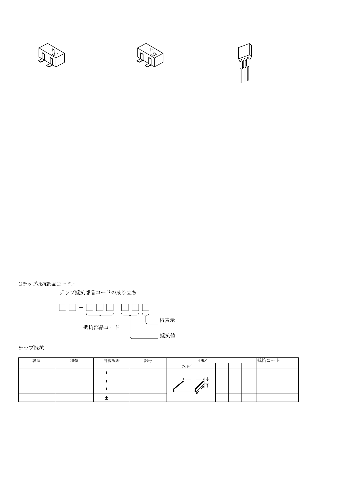
CHIP RESISTOR PART CODE
Chip Resistor Part Coding
88
A
Resistor Code
Chip resistor
Wattage Type Tolerance
1/16W 1005 5% CJ
1/16W
1/10W
1/8W
1608
2125
3216
5%
5%
5%
Symbol
CJ
CJ
CJ
Figure
Value of resistor
Form
L
Dimensions (mm)
t
W
0.55
Resistor Code
108
118
128
LW t
1.0 0.5 0.35 104
1.6 0.8 0.45
2 1.25 0.45
3.2
1.6
: A
: A
-4-
Page 5
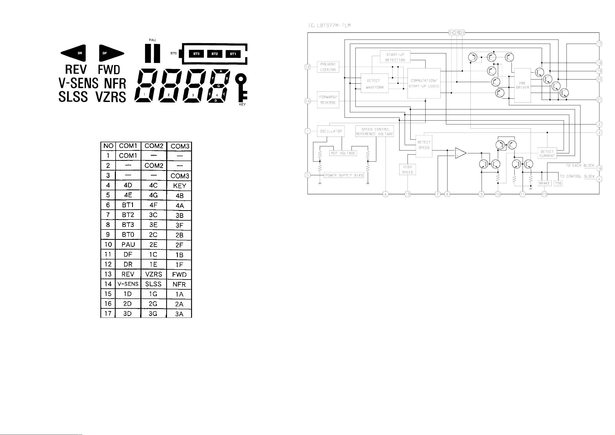
LCD DISPLAY
LCD, AHT-2
IC BLOCK DIAGRAM
-5-
Page 6

WIRING-1 (MAIN / RP HEAD FLEX / E HEAD FLEX)
-6-
Page 7

WIRING-2 (SWITCH)
-7-
Page 8

SCHEMATIC DIAGRAM (MAIN / SWITCH / RP HEAD FLEX / E HEAD FLEX)
-8-
Page 9

ADJUSTMENT
1. Tape Speed (4.8 cm/s) Adjustment 1
Settings : Test tape : TTA-100 (TAPE CENTER)
Test point : PHONES JACK (J102)
Adjustment location : SFR301
PAUSE : OFF
REC MODE SW : NORM (4.8 cm/s)
VOLUME : Maximum
TAPE SPEED : Normal (Speed volume center)
Method : Play back the test tape and adjust SFR301 for 3000 Hz
± 10 Hz (FWD). Then confirm that the speed at the
reverse side is FWD speed ± 45 Hz (REV). Then the
confirm wow is less than 0.55 %.
2. Tape Speed (2.4 cm/s) Adjustment 2
Settings : Test tape : TTA-160 (TAPE CENTER)
(6 kHz tape)
Test point : PHONES JACK (J102)
Adjustment location : SFR302
PAUSE : OFF
REC MODE SW : EXT (2.4 cm/s)
VOLUME : Maximum
TAPE SPEED : Normal (Speed volume center)
Method : Play back the test tape and adjust SFR302 for 3000Hz ±
10 Hz. Then the confirm wow is less than 1.0%.
-9-
Page 10

IC DESCRIPTION
IC, TC9318FB-061
Pin No. Pin Name I/O Description
1 ~ 3 COM1 ~ COM3 O LCD driver common.
4 ~ 18 S1 ~ S15 O LCD driver output.
19 S16/KR7 O LCD driver output/Key return.
20 ~26 S17/KR6 ~ S23/KR0 O LCD driver output (not used)/Key matrix timing output.
27 ~ 30 K0 ~ K3 I Key matrix input.
31 MOT ON O Motor activation control. H : ON L : OFF.
32 MOT HI O Motor speed control. H : HI L : LO.
33 MOT DIR O Motor rotate direction control. H : CCW L : CW.
34 MOT BRAKE O Motor brake control. H : ON L : OFF.
35 LOAD CTL O Battery capacity check signal output. H : ON.
36 4.8/2.4 O Tape speed control. H : 4.8 L : 2.4.
37 F/R CTL O FWD/REV control. H : FWD L : REV.
38 P/R CTL O Record/Playback power control. H : PLAY L : REC.
39 TIMING SW I Mecha status detection switch input.
40 EJECT SW I Mecha EJECT detection switch input.
41 STOP CTL O AMP power control signal output. H : ON L : OFF.
42 L.V.STOP I Reduction voltage detection signal input. L : Reduce voltage.
43 KEY IN I Main key input.
44 NC I Not connected.
45 SLSS O SLSS control signal output. H : SLSS disable L : SLSS enable.
46 VZRS O VZRS control signal output. H : VZRS disable L : VZRS enable.
47 P-MUTE O Mute signal output. H : ON L : OFF.
48 TEST I TEST mode control input. (connected to ground)
49 P-SNSR I Photo sensor signal input.
50 SLSS PAUSE I SLSS PAUSE signal input. H : OFF L : ON.
51 S-MUTE O Mute signal output. H : ON L : OFF.
52 NC O Not connected.
53 GND – Connected to ground.
54 ~ 55 NC I Not connected.
56 VDD – Power supply.
57 RESET I System reset signal input.
58 XOUT
59 XIN – Crystal oscillator connection terminal.
60 VXT
61 VLCD – Reference voltage for LCD drive.
62 ~ 63 C1 ~ C2 – Voltage booster for LCD drive.
64 VEE – 1.5V fixed power supply for LCD drive.
-10-
Page 11

IC, LB1977M-TLM
Pin No. Pin Name I/O Description
1 OSC – Oscillation terminal for activate.
2 COM O Comparator voltage for detection output waveform.
3VSI
4 GND – Connected to ground.
5 S/S I Start/Stop terminal.
6 VREF – Reference voltage (0.9V).
7 IN+ I Non reverse for differential AMP.
8 VSP O Output for output waveform's wave height detection.
9 OUT O Differential AMP output.
10 RI – Current feedback resistor connection terminal.
11 FC – Frequency response adjustment terminal.
12 LB – Prevent motor locking when activating motor (connected to ground through a capacitor).
13 HS – Hi speed (1.5 times speed as normal). (connected to ground)
14 DR I Forward/reverse rotate direction.
15 BRAKE I Brake terminal. (Brake : MC OFF and U, V, W OUT ON)
Detect speed and voltage comparison for current feedback circuit. (Connected to motor com
terminal)
16 VCC – Power supply.
17 MC O Drive terminal for external PNP transistor.
18 U OUT O Phase U output.
19 V OUT O Phase V output.
20 W OUT O Phase W output.
21 P-GND – Ground for output transistor and pre-driver
22 WB – 3 differential AMP phase W base terminal.
23 VB – 3 differential AMP phase V base terminal.
24 UB – 3 differential AMP phase U base terminal.
.
-11-
Page 12

MECHANICAL EXPLODED VIEW 1 / 1
1
2
3
4
7
5
25
27
6ZM-2
26
A
10
11
J
E
22
H23
J
28
E
I
18
LCD
19
H
24
29
12
B
B
13
14
15
C
C
B
SH,PWB
6
8
9
A
16
17
PWB,
FLEX
P.C.B
C
30
35
32
33
40
H
G
38
39
F
F
39
34
P.C.B
H
36
37
G
31
21
20
D
C
TP-S90 TP-VS805
(FileName:EXP.EPS)
2000/6/16
-12-
Page 13

MECHANICAL PARTS LIST 1 / 1
1 8A-HT2-019-010 PANEL,MIC
2 8A-HT2-024-010 HLDR,MIC
3 8A-HT2-204-010 COVER, MIC
4 87-A91-877-010 MIC,ECM 0B0-081N-0B
5 8A-HT2-010-010 PANEL,FRONT Y
6 8A-HT2-008-010 WINDOW,CASS
7 8A-HT2-013-010 KNOB,SL MODE/MIC
8 8A-HT2-002-010 LID,CASS Y
9 8A-HT2-015-010 KNOB,SL REC
10 8A-HT2-018-010 BTN,REPEAT
11 8A-HT2-016-010 BTN,ST/PL/PA
12 8A-HT2-025-010 BTN,RESET
13 8A-HT2-017-010 BTN,FF/REW
14 8A-HT2-020-010 LENS,LED
15 8A-HT2-021-010 BTN,REC
16 8A-HT2-212-010 SPR,REC
17 87-A91-821-010 SPKR,36 8OHM 0.8W 36L8B8W
18 8A-HT2-205-010 HLDR,LCD
19 8A-HT2-206-010 CONN,RUBBER LCD
20 8A-HT2-201-010 HLDR,CASS
21 88-HJ3-203-010 SPR-P,CLICK
22 8A-HT2-004-010 FRAME,CENTER Y
23 87-HR6-219-010 SPR-P,POP UP
24 8A-HT2-203-010 HLDR,PWB
25 88-HJ3-208-010 NUT, FRONT
26 8A-HT2-011-010 KNOB,SL OPEN
27 8A-HT2-210-010 PLATE,LOCK
28 8A-HT2-211-010 SPR,EJECT
29 88-HJ3-205-010 SPR-P,CASS
30 87-HJ3-608-010 SW,LEAF REC ASSY
31 8A-HT2-202-010 PLATE,HINGE
32 8A-HT2-007-010 LID,BATT
33 8A-HT2-208-010 BAT-CONTACT,(+)HINGE
34 8A-HT2-213-010 SHAFT,BATT
35 8A-HT2-207-010 BAT-CONTACT,(-)SPR
36 8A-HT2-006-010 CABI,REAR Y
37 8A-HT2-012-010 KNOB,SL SLSS/VZRS
38 8A-HT2-014-010 KNOB,SL HOLD
39 8A-HT2-214-010 FOOT,RUBBER
40 8A-HT2-209-010 HLDR,DCJACK
A 87-264-505-310 SCREW,V+1.4-2.5
B 87-264-503-310 SCREW V+1.4-2
C 87-067-732-010 TAPPING SCREW, VT1.4-3
D 87-263-500-010 SCREW V+1.4-1.4
E 87-HK5-235-010 S-SCREW,1.4-0.6-2.5
F 87-067-768-010 VT2+1.7-7
G 87-264-508-310 SCREW,V+1.4-3.5
H 87-067-535-010 S-SCREW,VT+1.4-3.5 WHT HL
I 88-HK5-228-010 S-SCREW,+1.4-2 CR
J 87-078-137-010 S-SCREW,+1.4-1 SWCH/CR NLOCK
-13-
Page 14

TAPE MECHANISM EXPLODED VIEW 1 / 1
E HEAD FLEX C.B
RP HEAD FLEX C.B
41
50
51
SH,1.2-2.9-0.25SL
1
8
13
B
B
52
A
6
E
2
3
4
d
6
43
10
42
5
7
9
b
c
a
SH,1.2-2.9-0.25SL
43
11
49
40
c
b
e
d
f
34
38
SHAFT
CAPSTAN
a
35
24
D
16
H
39
W1.76-4-0.3
15
W-L,1.31-3-0.2
20
23
22
40
44
G
54
G
W1.57-3-0.3
e
20
21
22
25
17
W0.8-3.0-1.25
SHAFT CAPSTAN
26
45
12
19
30
E
28
27
29
14
D
31
32
F
38
f
48
46
47
33
C
37
F
36
F
18
-14-
Page 15

TAPE MECHANISM PARTS LIST 1 / 1
39 86-ZM2-292-010 1A FLY WHL,R ASSY
48 86-ZM2-291-010 1A FLY WHL,L ASSY
1 86-ZM2-255-010 0E SPR-T,PIN BACK L
2 86-ZM2-286-410 0E GUIDE,TAPE REC
3 86-ZM2-220-210 0E SPR-T,HEAD
4 86-ZM2-285-210 0E LEVER,HEAD REC
5 86-ZM2-347-010 0E LEVER,MS EJECT
6 86-ZM2-226-110 0E ROLLER ASSY,PINCH
7 86-ZM2-254-010 0E SPR-T,PIN BACK
8 86-ZM2-230-110 0E SPR-T,PINCH L
9 86-ZM2-229-110 0E SPR-T,PINCH R
10 86-ZM2-240-110 0E CAP,REEL
11 86-ZM2-234-110 0E SHAFT,REEL R
12 86-ZM2-251-310 0E SHAFT,GEAR B
13 86-ZM2-361-110 1C CHAS ASSY,OUT-SERT P10
14 86-ZM2-268-310 0E SHAFT,PULLEY BELT 2
15 86-ZM2-232-310 0E LEVER,REEL R
16 86-ZM2-306-010 0E SPR-C,BT 2
17 86-ZM2-243-310 0E SPR-C,BT
18 86-ZM2-329-210 0E BELT,P5
19 86-ZM2-209-310 0E GEAR,B
20 86-ZM2-238-710 0E GEAR,FF
21 86-ZM2-245-510 0E SPR-C,SLIP L
22 86-ZM2-237-010 0E GEAR,PLAY
23 86-ZM2-241-410 0E SPR-C,SLIP R
24 86-ZM2-272-010 0E LEVER,SW P 8.4
25 86-ZM2-236-510 0E CAP,SLIP
26 86-ZM2-235-210 0E SHAFT,REEL L
27 86-ZM2-223-310 0E LEVER,PIN UP L
28 86-ZM2-233-310 0E LEVER,REEL L
29 86-ZM2-208-310 0E GEAR,A
30 86-ZM2-217-210 0E SPR-E,CAM L
31 86-ZM2-216-510 0E LEVER,CAM L
32 86-ZM2-276-010 0E PULLEY,COUPLER
33 86-ZM2-212-310 0E SHAFT,FR
34 86-ZM2-214-510 0E LEVER,CAM R
35 86-ZM2-215-210 0E SPR-E,CAM R
36 86-ZM2-222-410 0E LEVER,PIN UP R
37 86-ZM2-218-410 0E LEVER,HEAD UP
38 86-ZM2-221-010 0E CLR,BRG N
40 86-ZM2-239-010 0E FELT,
41 86-ZM2-225-310 0E ARM,PINCH L
42 86-ZM2-224-210 0E ARM,PINCH R
43 86-ZM2-283-210 0E CAP,SHAFT
44 86-ZM2-275-310 0E CAP,SLIP R
45 86-ZM2-210-710 0E LEVER,FR
46 86-ZM2-211-210 0E GEAR,FR
47 86-ZM2-213-210 0E SPR-C,FR
49 86-ZM2-282-010 0E SH,AUTO 2
50 86-ZM2-342-110 1B LEVER ASSY,EJECT
51 86-ZM2-349-010 0E SPR-E,EJECT
52 8A-HT2-609-010 2A HEAD, ASSY AHT-2
53 86-ZM2-326-210 1C HEAD ASSY,EH 6ZM-2 R2
54 M8-6ZS-393-000 1H ABL-63 D
A 86-ZM2-338-010 0E W-L,1.47-2.4-0.125 W/ADH
B 86-ZM2-296-110 0E S-SCREW,+1.4-8.45
C 87-067-516-010 0E PW,3-1.58-0.25,SLIT
D 87-067-860-010 0E PW,3-0.95-0.4
E 86-ZM2-364-010 0E W-L,1.47-2.4-0.188 W/ADH 0.05
F 86-ZM2-319-010 0E W-L,0.95-3-0.35
G 88-HK5-228-010 0E S-SCREW,+1.4-2 CR
H 86-ZM2-278-010 0E W-P,1.36-4-0.2 SLT
I 87-261-500-310 0E SCREW V+1.4-1.4 (BK)
-15-
Page 16

211, IKENOHATA 1CHOME, TAITO-KU, TOKYO 110, JAPAN TEL:03 (3827) 3111
Printed in Singapore2000058 912204 0251431
 Loading...