

Page 1
MULTI-BAND RADIO STEREO
CASSETTE RECORDER
MDDELTPR-94DEE,uK
AIW~
(SERVICE MANUAL]
Type
Circuitry
Power source
Output
Powr consumption
Frequency response
Speakers 120 mmq,x2,
Multiband (FM/SW/MW/LW)
radio stereo cassette recorder
38 transistors, 24 diodes, 5 ICs,
1 LEO
Batteries, OC 9V(UM-1 x 6)
AC 110-120V/220-240
(switchable)
Car battery
5 W maximum (2.5 W+2.5 W)
12W
Normal
tape:
CrO,
tape :
Tape Recorder Section
Built-in microphones
Tape speed
Recording system
Erasing system
Recording time
Signal to noise ratio
Wow and flutter
Electret condenser microphones
4.8 cm/sec
AC bias
AC erase
90 minutes (C-90 cassette,
directions)
55 dB
0.09% (WRMS)
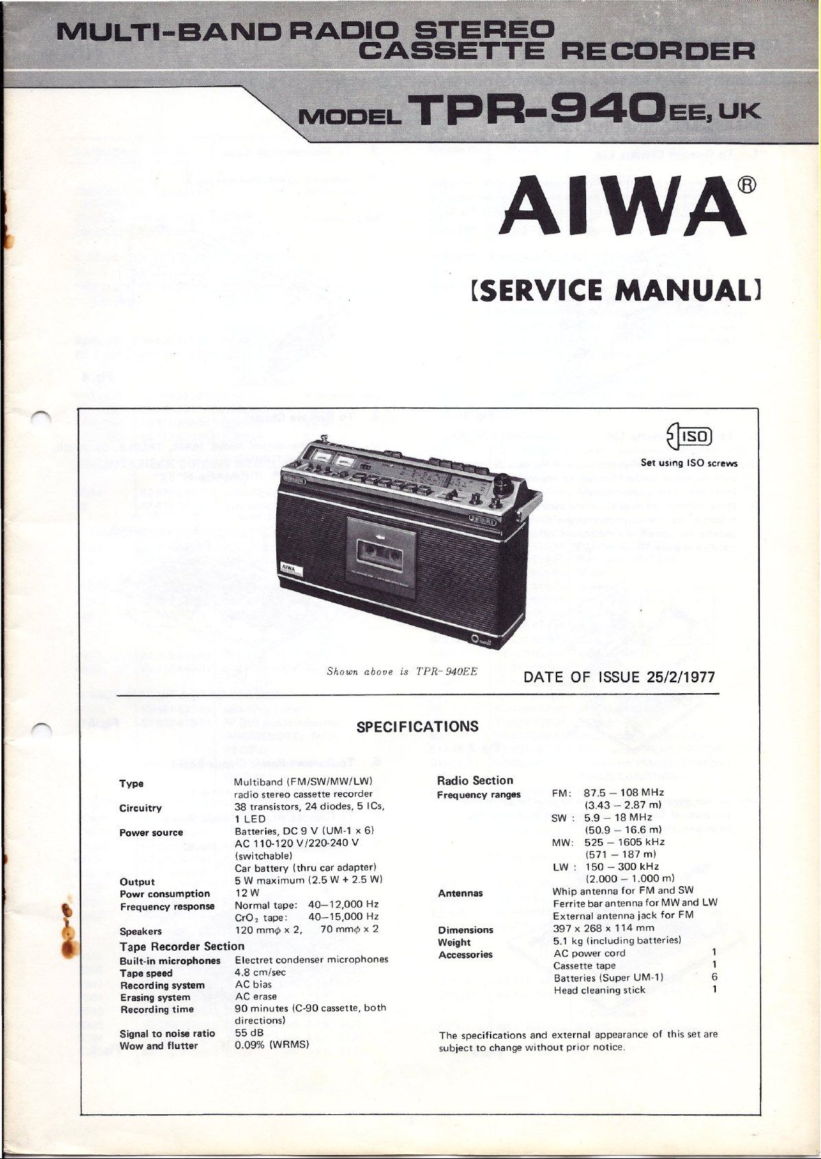
Shown above is TPR- 940EE
SPECIFICATIONS
V
(thru
car
adapter)
40-12,000 Hz
40-15,000 Hz
70 mrno
x
both
2
Set using ISO screws
DATE OF ISSUE 25/2/1977
Radio Section
Freq uency ranges
Antennas
Dimensions
Weight
Accessor ies
The specifications and external appearance of this set are
subject to change without prior notice.
FM: 87.5-108MHz
(3.43 - 2.87 rn)
SW: 5.9-18MHz
(50.9 - 16.6
MW: 525 - 1605 kHz
(571 - 187 m)
LW: 150 - 300 kHz
(2.000 - 1.000
Whip antenna for FM and SW
Ferrite bar antenna for MW and LW
External antenna jack for FM
397x268x114 mm
5.1 kg (including
AC power cord
Cassette tape 1
Batteries (Super UM-1) 6
Head cleaning stick
m)
m)
batteries)
Page 2

MODEL TPR-940EE, UK
DISASSEMBLY INSTRUCTIONS
AIWA
1. T0Remove Cassette Lid
1) While pressing hard the arrow-indicated parts (left and right)
in the directions indicated by the respective arrow marks in
figure, pull out the cassettelid for removal. (Refer to Fig. 1)
Fig.1
2. To Install Cassette Lid
1) Refering to figure, align the pawls of the cassettelid properly
with respective guides provided on the mechanism panel and
insert them into guides securely.
2) While pressingthe parts (1) of the cassettelid in the directions
indicated by the respective arrow marks, push the entire
cassette lid toward the mechanism panel until it is securely
installed in place. (Refer to Fig. 2)
3. To Remove Back Cover
1) Remove6 screws. (Refer to Fig. 4)
Fig.4
4. To Remove Chassis
1) Pull out the control knobs. (BASS, TREBLE, BALANCE,
VOLUME and TUNING).
2) Remove 8 screws. (Refer to Fig. 5)
Fig.2
Note: Do not remove or assemblethe cassettelid by force as
the parts of the cassettelid indicated by arrows might
bebroken. (Refer to Fig. 3)
Fig.3 Fig.6
Fig.5
v
5. To Remove Power Circuit Board
1) Remove2 screws. (Refer to Fig. 6)
6. To Remove Rec'/Pb Circuit Board
1) Remove4 screws. (Refer to Fig. 6)
2
Page 3

AIWA
MODEL TPR-940EE, UK
7. To Remove Recorder Chassis
1) Remove3 screws. (Refer to Fig. 7)
8. To Remove Tuner Circuit Board
1) Remove4 screws. (Refer to Fig.
Tuner
8)1
9. To Remove Volume Circuit Board
1) Remove2 nuts. (Refer to Fig.9)
10. To Remove Tone Circuit Board
1) Remove4 screws. (Refer to Fig. 9)
Fig.7
Fig.9
11. To Remove Switch-2 Circuit Board
1) Remove2 screws.(Referto Fig. 10)
Switch-2 Circuit Board
<v.
U(j)3-6
Fig.8
DIAL CORD INSTALLATION
Re'movethe tuner circuit board and perform dial cord installation
asfolIows.
1) Thread.dial cord through points (1) - (11).
2) Install tuner circuit board.
3) Turn tuning shaft counter-clockwise.
4) Set the dial indicator to the dial panelreferencemark. Engage
dial indicator with the cord andlock with cement.
VS(j)3-8
Fig.10
~52~5__
"71':
Align indicator with this mark.
3
Page 4

MO DEL TPR-940EE, UK
ADJUSTMENTS 4. Pinch Pressure
AIWA
MECHANIOAL SECTION
1. Review Timing Adjustment
During review operation, the pinch roller and play idler should
separate either simultaneously, or the pinch roller separates
first.
Adjustment
During play operation, depress the REW button. Adjust by
bending the operating tab forward or rearward to obtain the
abovetiming. (Refer to Fig. 11)
Operating tab
2. Pause Timing Adjustment
In pauseoperation, the pinch roller, play idler and leaf switch
all separate sirnultaneouslv, or the pinch roller separatesfirst.
Adjustment
During play operation, adjust by bending the operating tab
forward or rearward. (Reter to Fig. 12)
Fig.11
290±30g
5. Tape Speed Variation
±2%
Usea standard test tape, TTA-111 (3kHz) or equivalent.
Wow&Flutter
6.
0.08±0.04% (WARMS)
Usea standard test tape, TTA-111 (3kHz) or equivalent.
Takeup Torque
7.
+
5
50 -10 g-cm
8. Fast ForwardiRewind Torque
110±20 g-cm
9. Fast Forward Time
140±10 sec. (at C-60 tape)
10. Rewing Time
110±10 sec. (at C-60 tape)
11. Current Consumption
FWD: 115±25mA
FF: 160±25mA
REW: 215±30mA
(mechanism unit only)
3. Thrust Adjustment
Turn the thrust adjusting screw and adjust
spacing between it and the tlywheel. (Reter to Fig. 13))
tor
0.1 - 0.2mm
v
Fig.12
Fig.13
4
Page 5
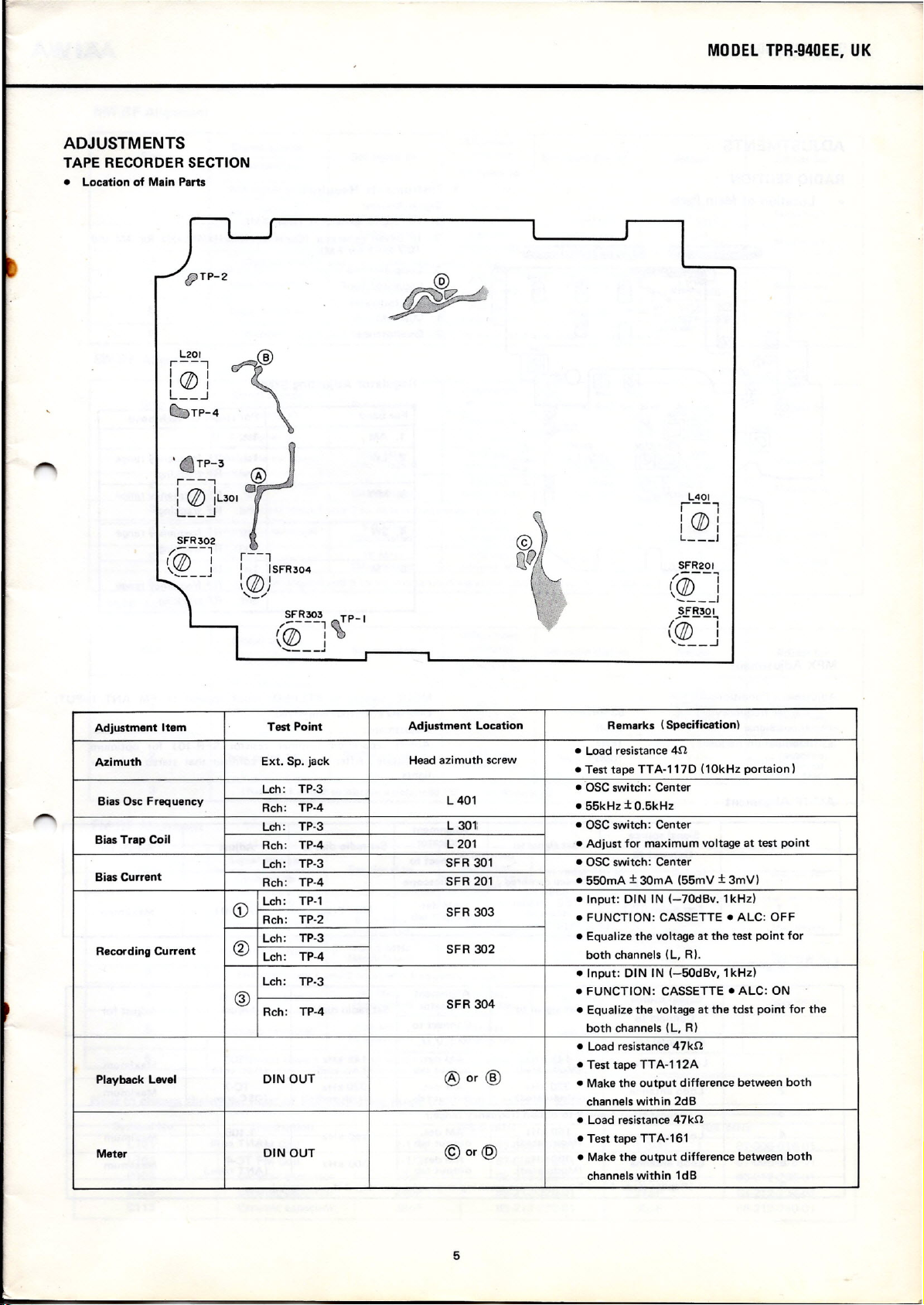
ADJUSTMENTS
TAPE RECORDER SECTION
• Location of Main Parts
L201
r----,
I 171\ I
I \V 1
L__
...l
_TP-4
MOOEL TPR·940EE, UK
\
r--"
i
L__
SFR302
/---1
1171\ I
''!!:!__
Adjustment Item
Azimuth
Bias Osc Frequency
Bias Trap Coil
Bias Current
Recording Current
Playback Level
Meter
(Jj)
-.!
J
iL301
r
r--l
I
1171\
'\VI
,_/
CD
®
®
ISFR304
I
SFR303
(~--i
\\V
......_-_..1
Test Point
Ext. Sp. jaek
TP-3
Leh:
TP-4
Reh:
Lch:
Tp·3
TP-4
Reh:
TP-3
Leh:
Reh: TP-4
Leh: TP-1
TP-2
Reh:
TP-3
Leh:
Leh: TP-4
Leh:
TP-3
TP-4
Reh:
DIN OUT
DIN OUT
L401
---.,
I I
I
(fJ)
I
I
I
L
l
SFR201
/(jf)---'
I, I
____ J
SFR301
~P-I
I
Adjustment Location
Head azimuth serew
L401
L 301: • OSCswiteh: Center
L 201
SFR 301 • OSC switeh: Center
SFR 201
SFR 303
SFR 302
SFR 304
®
or
®
©or@
Remarks (Specification)
• Load resistanee 4n
• Test tape TTA·117D (10kHz portaion l
.OSC switch: Center
• 55kHz±0.5kHz
.• Adjust for maximum voltage at test point
• 550mA±30mA (55mV±3mV)
• Input: DIN IN (-70dBv. 1kHz)
• FUNCTION: CASSETTE • ALC: OFF
• Equalize the voltaqs at the test point for
both ehannels (L, R).
• Input: DIN IN (-50dBv, 1kHz)
• FUNCTION: CASSETTE • ALC: ON
• Equalize the voltage at the tdst point for the
both ehannels (L, R)
• Load resistanee47kn
• Test tape TTA-112A
• Make the output differenee between both
ehannels within 2dB
• Load resistanee47kn
• Test tape TTA-161
• Make the outout differenee between both
ehannels within 1dB
((jf)'---'
\ I
' ...l
5
Page 6
MODEL TPR·940EE, UK
ADJUSTMENTS
AIWA
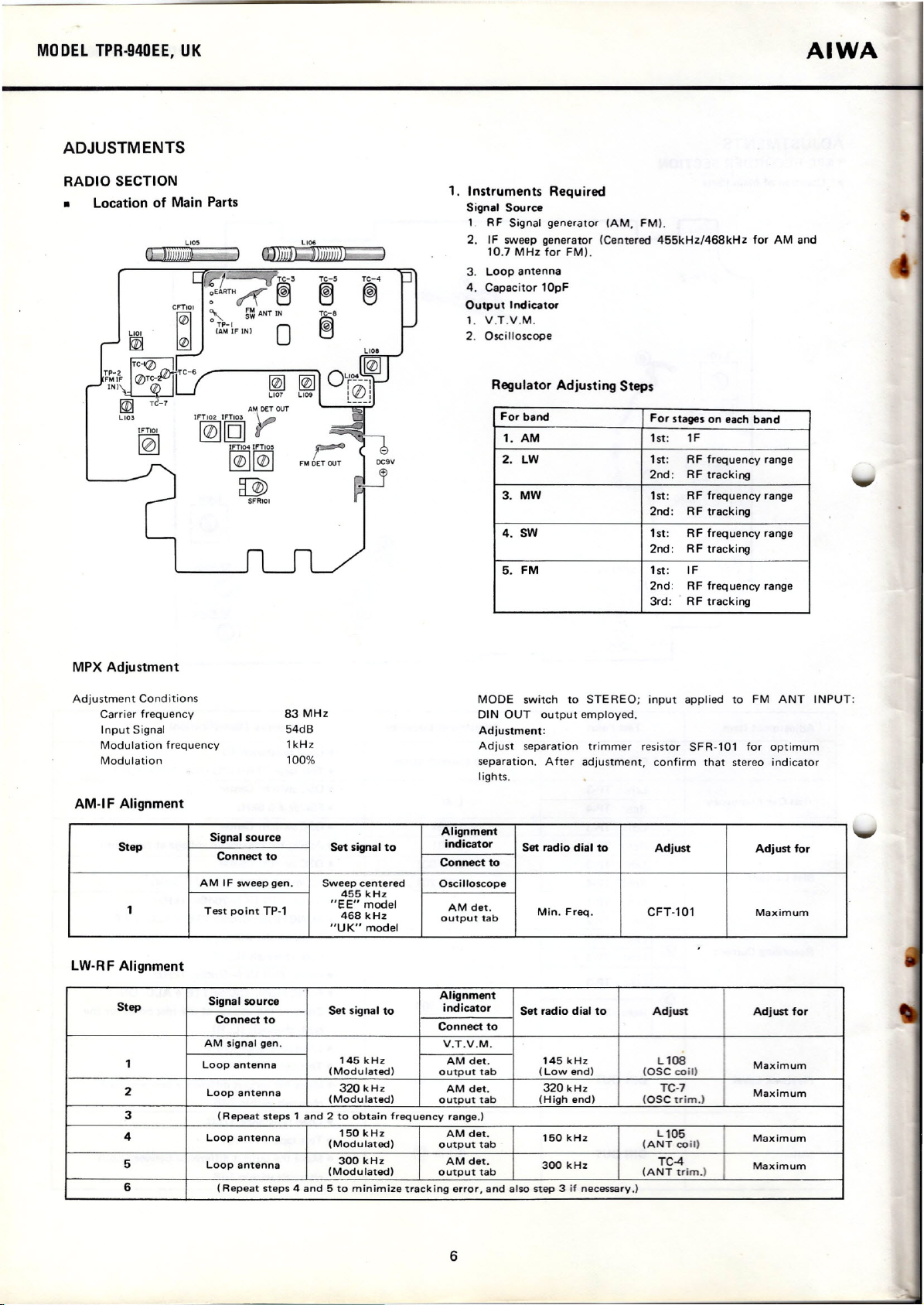
RADIO SECTION
• Location of Main Parts
Ll05
t.tot
~
IFTIOI
IF~I[gJ
[@
AM DET OUT
tr
IFTI04 IfTI05
~~
~
SFRIOI
1. Instruments Required
Signal Source
1 RF Signal generator (AM. FM).
2. IF sweep generator (Centered 455kHz/468kHz for AM and
10.7 MHz for FMl.
3. Loop antenna
4. Capacitor 10pF
Output Indicator
1.
V.T.V.M.
2. Oscilloscope
Regulator Adjusting Steps
For band
1. AM
LW
2.
MW
3.
4. SW 1st: R F frequency range
FM
5.
For stages on each band
1st: 1F
1st:
RF frequency range
2nd: RF tracking
1st: RF frequency range
2nd: RF tracking
2nd: R F tracking
1st:
IF
2nd:
RF freq uency range
3rd: RF tracking
MPX Adjustment
Adjustment Conditions
Carrier frequency
Input Signal
Modulation frequency
Modulation
AM-IF Alignment
Step Set signal to
1
LW-RF Alignment
Step
1
2
3
4
5
6
83 MHz
54dB
1kHz
100%
Signal source
Connect to
AM IF sweepgen.
Test point TP·1
Signal source
Connect to
AM signal gen.
Loop anten na
Loop antenna
(Repeat steps1and 2 to obtain frequency range.)
Loop antenna
Loop antenna
(Repeat steps4and5to minimize tracking error, and also steo3if necessary,)
Sweep centered
455
kHz
"EE" model
468
kHz
"UK" model
Set signal to
145
kHz
(Modu lated)
320 kHz AM det. 320 kHz
(Modulated)
150
kHz
(Modulated)
300
kHz
(Modulated)
MODE switch to STEREO; input applied to FM ANT INPUT:
DIN OUT output employed.
Adjustment:
Adjust separation trimmer resistor SF R-101 for optimum
separation. After adjustment, confirm that stereo indicator
lights.
Alignment
indicator
Connect to
Oscilloscope
AM det.
output tab
Alignment
indicator
Connect to
V.T.V.M.
AM det.
outpur tab
output tab
AM det.
outpur tab
AM det.
output tab
Set radio dial to
Min. Freq.
Set radio dial to
145
kHz Ll08
(Lowend) (aSe coi!)
(High end) (oac trirn.)
150
kHz
300
kHz
Adjust
CFT·l0l
Adjust
TC-7
L105
(ANT co
(ANT trirn.)
it)
TC-4
Adjust for
Maximum
Adjust for
Maximum
Maximum
Maximum
Maximum
6
Page 7
AIWA
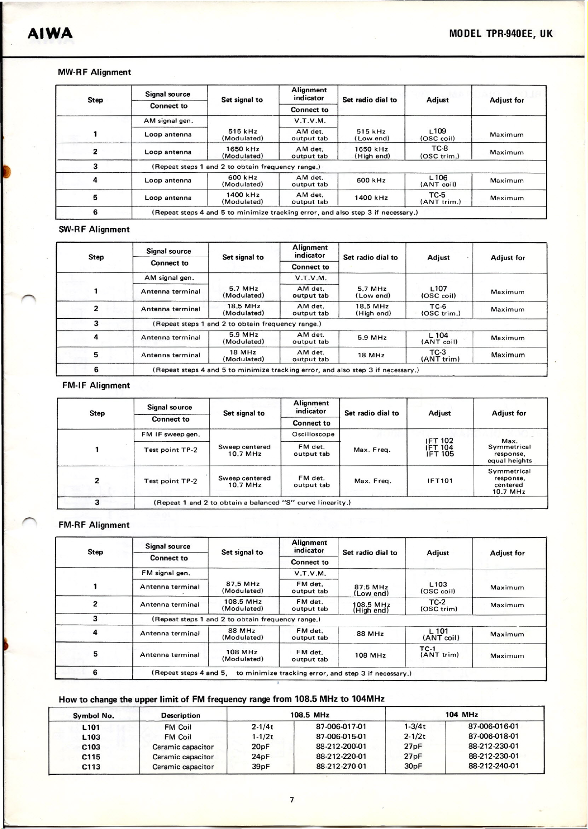
MW-R F Alignment
MODEL TPR-940EE, UK
Step
1 Loop antenna
2
3
4 Loop anten na
5
6
SW-RF Alignment
Step Set signal to
1 Antenna terminal
2
3
4
5
6
FM-I F Alignment
Signal souree
Conneet to
AM signal gen. V.T.V.M.
Loop anten na
(Repeat steps 1 and 2 to obtain frequency range.)
Loop antenna
(Repeat steps 4 and 5 to minimize tracking error, and also step 3 if necessary.)
Signal souree
Conneet to
AM signal gen.
Antenna terminal
(Repeat steps 1 and 2 to obtain frequency range.)
Antenna terminal
Antenna terminal
(Repeat steps 4 and 5 to minimize tracking error, and also step 3 if necessary.)
Set signal to
515kHz
(Modulated)
1650kHz
(Modulated)
600 kHz AM det.
(Modulated) output tab (ANT coil)
1400 kHz AM det.
(Modulated) output tab (ANT trtrn.)
5.7 MHz AM det.
(Modulated)
18.5 MHz
(Modulated)
5.9 MHz
(Modulated)
18 MHz AM det.
(Modulated)
Alignment
indicator
Connect to
AM det. 515 kHz Ll09
output tab
AM det. 1650 kHz
output tab (High end)
Alignment
indicator
Connect to
V.T.V.M.
output tab (Lowend) (OSC coi l)
AM det. 18.5 MHz
output tab (High end) (OSC tr im.)
AM det.
output tab
output tab (ANTtrim)
Set radio dial to
(Lowend)
600 kHz
1400 kHz
Set radio dial to
5.7 MHz Ll07
5.9 MHz
18 MHz
Adjust
(OSC coil)
TC-8
(OSC trim.)
Ll06
TC-5
Adjust Adjust tor
TC-6
L 104
(ANT co
it)
TC-3
Adjust tor
Maximum
Maximum
Maximum
Maximum
Maximum
Maximum
Maximum
Maximum
Step Set signal to
1
2
3
Signal souree
Connect to
FM IF sweep gen.
Test point TP-2
Test point TP-2
(Repeat 1 and 2 to obtain a balanced
FM-RF Alignment
Step Set signal to
1 Antenna terminal
2
3 (Repeat steps 1 and 2 to obtain frequency range.)
4
5
6
Signal souree
Conneet to
FM signal gen.
Antenna terminal
Antenna terminal
Antenna terminal
(Repeat steps 4 and 5,
Alignment
indieator
Connect to
OsciIloscope
Sweep centered FM det.
10.7 MHz output tab
Sweep centered FM det.
10.7 MHz
87.5 MHz FM det.
(Modulated)
108.5 MHz FM det.
(Modulated) outpur tab
88 MHz FM det.
(Modulated)
108 MHz
(Modulated)
to minimize tracking error, and step 3ifnecessarv.)
outpur tab
"5"
curve linearity.)
Alignment
indieator
Conneet to
V.T.V.M.
outpur tab
output tab
FM det.
outpur tab
Set radio dial to Adjust Adjust tor
Max. Freq.
Max. Freq. IFT101
Set radio dial to
87;5 MHz
(Lowend)
108.5 MHz
(High end)
88 MHz
108 MHz
.
1FT 102
1FT 104
1FT 105
Adjust Adjust for
L103
(OSC coil)
TC-2
(OSC tr lrn)
L 101
(ANT coil)
TC-1
(ANT trim)
Symmetrical
response,
equal heights
Symmetrical
response,
centered
10.7 MHz
Maximum
Maximum
Maximum
Maximum
Max.
.-
How to change the upper limit of FM frequency range from 108.5 MHz to 104MHz
Symbol No.
L101
L103
C103
C115
C113
Deseription
FM Coil
FM Coil
Ceramic capacitor
Ceramic capacitor
Ceramic capacitor 39pF
2-1/4t
1-1/2t
20pF
24pF
108.5 MHz
87-006-017-01
87-006-015-01
88-212-200"-01
88-212 -220-0 1
88-212 -270-0 1
7
1-3/4t
2-1/2t
27pF
27pF
30pF
104 MHz
87-006-0 16-01
87-006-018-01
88-212-230-01
88-212-230-01
88-212-240-01
Page 8
MODEL TPR·940EE, UK
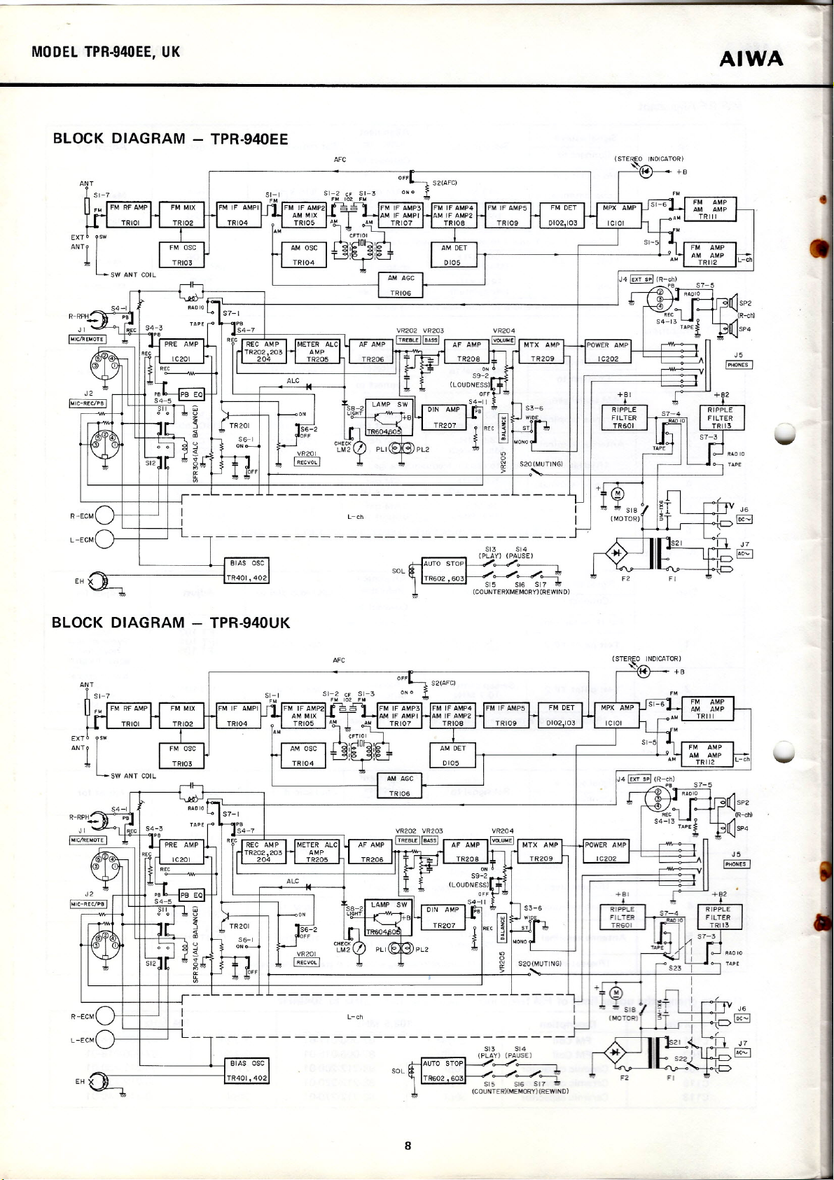
BLOCK DIAGRAM - TPR·940EE
ANT
AIWA
AFC
BLOCK DIAGRAM - TPR·940UK
ANT
L-ch
513 514
(PLAY) (PAUSE)
SOL
AFC
~
~~J"
815 516 S~
(COUNTER){MEMORY) (REWIN 0)
L-ch
513 514
(PLAY) (PAUSE)
SOL
~
~~J"
$15 $16 5:;---'
(GOUNTER)(MENORY){REWINO)
8
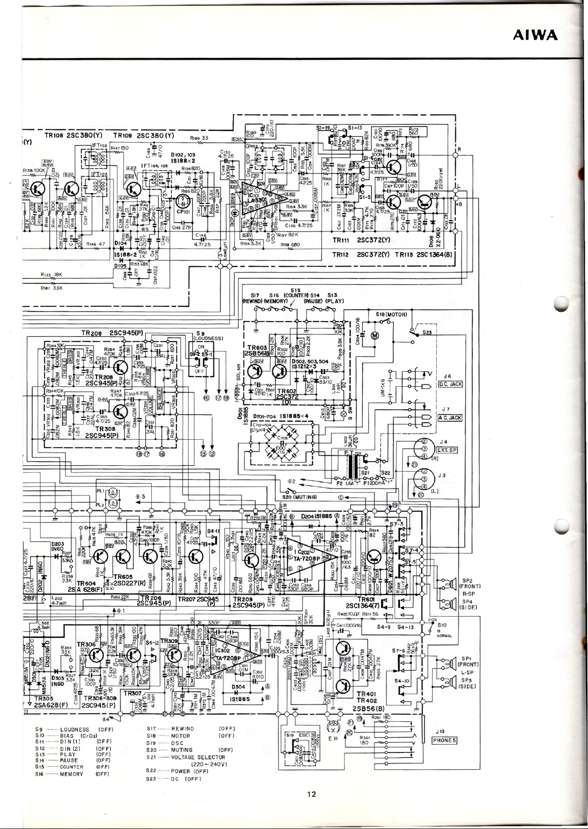
Page 9
AIWA
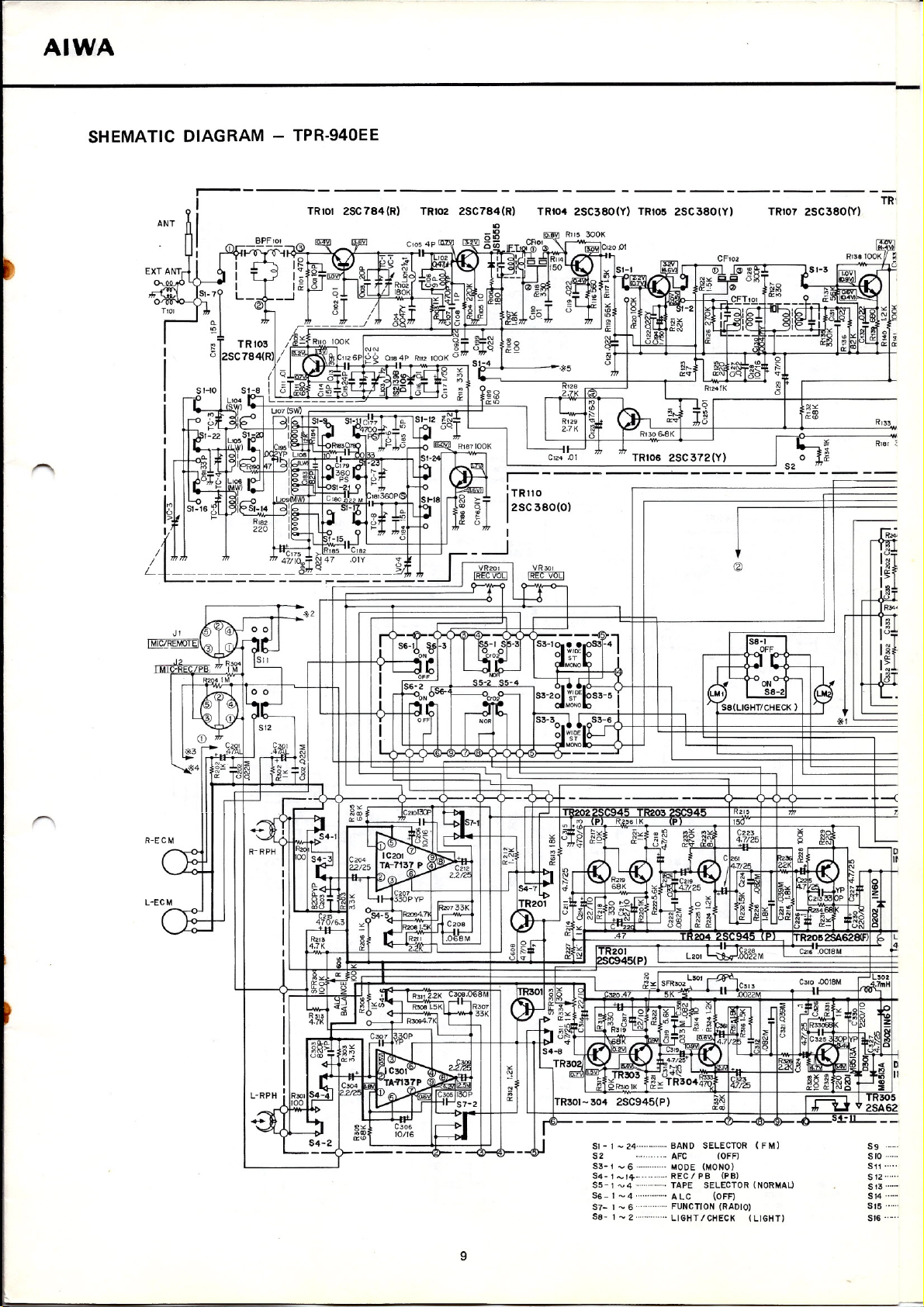
SHEMATIC DIAGRAM - TPR-940EE
ANT
.----
I
I
------------------------------------
TR10l 2SC784(R) TR102 2SC784(R)
TR104 2SC380(Y) TRIOS 2SC380(Y) TR107 2SC380(Y)
TR'
RI81 ~
R-ECM
CE
L-ECM
Clfr-
~~~w
8
1--~!(;::=t!iJ;~o~TI':l~:!~H~
L-RPH
~'rOp;IO.;;.O~
..a ~
~~~ . I
I
L...._,~~
R·;;;,....:.J
I
:7:~ r~'07
I
ß~>- ~~
4- "''''.
I
I
R301
54-2 ~~
'------()-- - - --<)rJ
'~~"'2'2K
Li! ~(/): I R30B
O----f-J
~~O:YJA·7K~
IC301
C304
~~TA.:n37P
22m
J.I I
8'"
C'06
10/16
I
I
2
LSOl ~ L502
Ci'Y:.
SFR302
1 .,
068M
C'l't.
1,5K ••
KI
L
~.~,J!i! '"
(9 2.
~30P '" '''' ~
rr·n-057-2
1'---;'1
l~
~
R'07 R:
33K
-1>'" "'"
r-~3~
$4-8
_TR302j
C\J
N ~
I
I
~Hil ~
TR30I-304 2SC945(P)
il---- -- -
C",o
47
g-:
N OO"N~
l~
I~
0
tl~I.!E~~~&~;~
IQ;IT~ TR303
5R3l01K
51_ 1 _
52 AFC (OFF) 5ro ..
53-
t -
54-1 -14- REC / PB (PB)
55 -
1- 4.. .
56-1 -4" ALC (OFF)
57- 1 - 6" FUNCTlON (RADIO)
58- 1 - 2 LIGHT ICHECK (LIGHT)
5K .OC22M '00'-
~J,g ~
<l>
zs -
§~Y~~i
C319~··
~4;~5~.
N
u<::t,
&=TR3044'~ 47/25
----<?---<Hl>--O--~±:ll....---,
24·
BAND 5ELECTOR (F M) 59
6 MODE (MONO) 511 .
TAPE 5ELECTOR (NORMALJ
lc313
I'"''
r".... ~;;
I~ ili
::!:
_~T ~
",~l
l~
C323
.;!~ I,J,
III .~ '"
I~~
C310·Q01eM J7mH
0
~d ~
~tt~~K
~N~N
-IV ~
~iii ~ ;;\
CD~re00
&1§ ~ ~~ ~
:~j
0~
TR305
'U 2SA62
512"
513
514 .
515 .
516 .....
--(
u
ro
in
11
9
Page 10
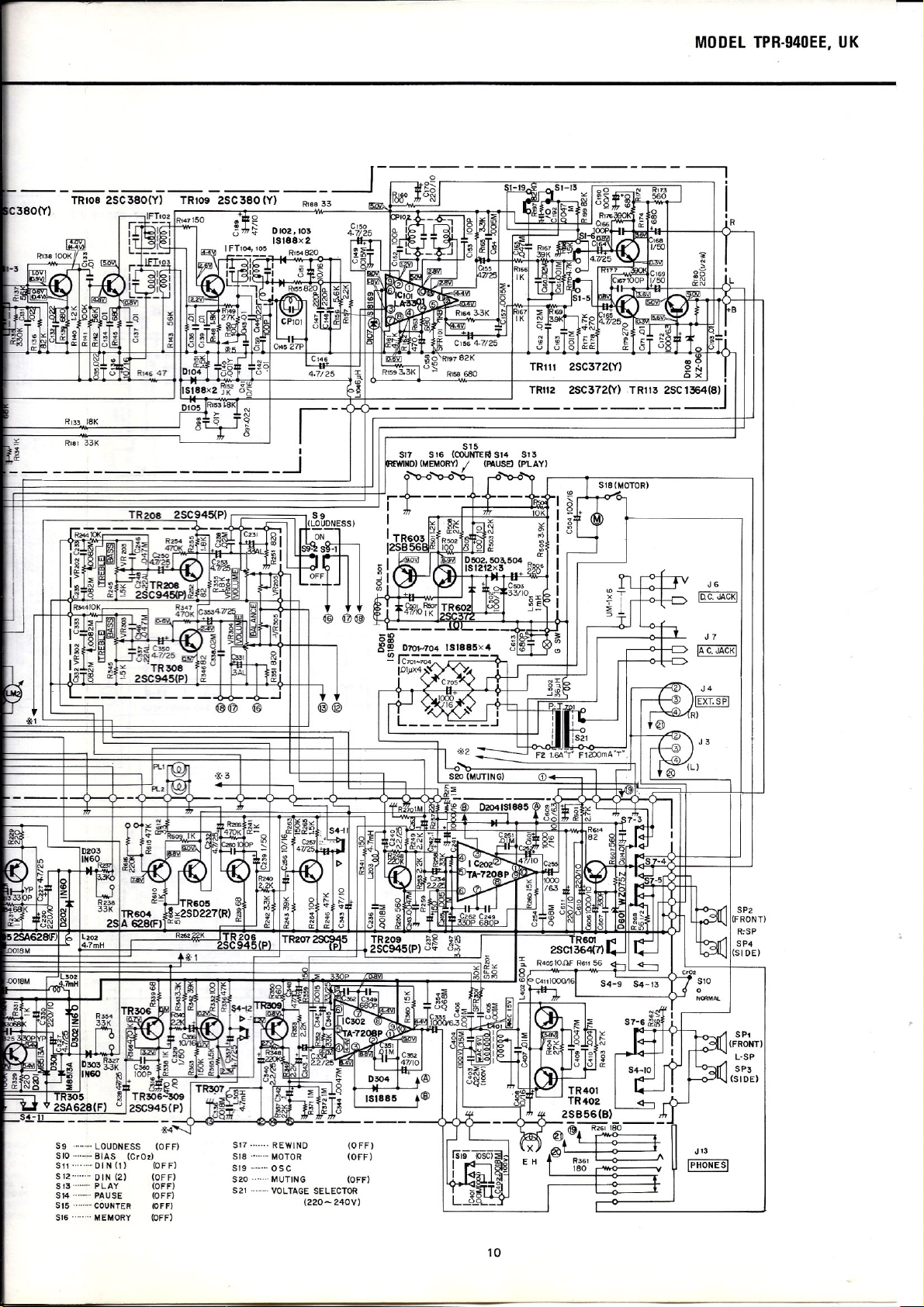
MODEL TPR-940EE, UK
RI33 J8K
~ I
~ -.J
RISI 33K
-
----
TR112 2SC372(Y) TRl13 2SC 1364(SIJ
----------------------
I
J
7
IAc.JACKI
S9 ,.. LOUONESS (OFF)
SIO , BIAS (CrO.)
S" ,·OIN(ll (OFF)
S'2 OIN (2) (OFF)
S
'3"
PLAY (OFF)
S14 , PAUSE (OFF)
S15' '''COUNTER (OFF)
S'6 .. MEMORY (OFF)
S'7 REWINO
SIB ..MOTOR
SI9 ...•... OSC
S20 MUTING
S21 VOLTAGE SELECTOR
(220- 240V)
(OFF)
(OFF)
(OFF)
J
.3
IPHONESI
10
Page 11
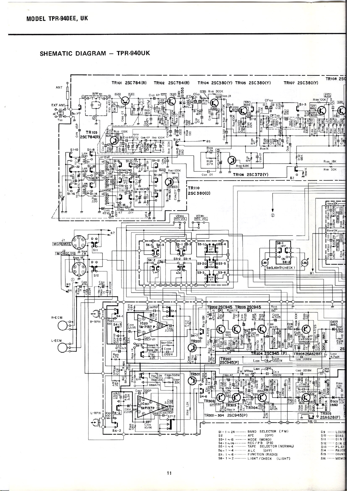
MODEL TPR-940EE, UK
SH EMATIC DIAG RAM - TPR-940U K
r--------
I
ANT
TRlol 2SC784(R) TRI02 2SC784(R) TR104 2SC380(Y) TR105 2SC 380(Y) TR107 2SC380(Y)
I
R-ECM
SI - 1 - 24 BAND SELECTOR (F M)
S2 AFC (OFF)
S3- 1 - 6· ... MODE (MONO)
S4- 1 _14-·- . REC / PB (PB)
S5- 1 -4 TAPE SELECTOR (NORMAU
S6-1-4···············ALC (OFF)
S7- 1 -
6·
SB- 1
-2··············
FUNCTION (RADIO)
LIGHT/CHECK (LIGHT)
S9 LOUD
S/O BIAS
SII DI N (
S
12·······DIN (
SI3·········PLAY
SI4·········PAUS
515 COUN
S/6 MEM
11
Page 12
IIY)
AIWA
R'33 leK
Rial 33K
____________ .-J
TRI12 2SC372(Y) TR113 2SC1364(8)J
-
---------------------------
1
I
1
I
I
I
I
i
J6
ilIlC. JACKI
I
I
I
J
7
IIAc..lACKl
________ J
I
59 LOUDNESS (OFF)
510 ·.. BIAS (CrO.)
SII' "DIN(ll (OFF)
S12' "DIN(2) (OFF)
SI3 · PlAY (OFF)
S!4 PAUSE (OFF)
S15' COUNTER 10FFI
SI6 MEMORY (OFF)
517 REWINO
518" .. MOTOR
SI9 .... ·0SC
S20 MUTING (OFF)
S21 VOl TAGE SElECTOR
S22 POWER (OFF)
S23 OC (OFF)
1220- 240V)
(OFF)
(OFF)
S?2
(FRONT)
R,S?
SP4
(SI DE)
L·S?
SP3
(SIDE)
J 13
I?HONESI
12
Page 13

AIWA
WIRING 1 - TPR-940EE
E.H
PLl
(METER)
PL2
(DIAL)
BLU
BLU
BLK
RN
RG
RED
(TAPE SELE
BLU
55
o
o
BATTERY BOX
e
S21
VOLTAGE)
(
SELECTOR
RED
PUL
~ ~ 4 WHT BLK
P.C.a-A{"~;;~=i==i$S:=ij====t=t~LtEK=f==t===
CD-
RED BlU
RED
GRN
P.C;B-G(VOWME CIRCUIT BOARD) '-- _
BRN
PUL
GRY
BLK
P.
13
Page 14

MODEL TPR-940EE, UK
PIN-A
YEl
P.C.B-E
(REC/PB CIRCUIT BOARD)
ORG
14
Page 15

MODEL TPR-940EE, UK
WIRING 1 - TPR-940UK
E.H
(METER)
PLl
o
RED
P.G.B-G(VOLUMECIRCUITBOARD) \
15
'!I
Page 16

AIWA
.)
YEL
P.CB-E
(REC/PB CIRCUIT BOARD)
(FRONT) (SIDE)
16
Page 17

AIWA
WIRING 2
MODEL TPR·940EE, UK
:u
rn
"
I
o
r
rn
o
("")
;;;
("")
c
-;
~
o
'"
."
<
("")
r
Ci
<1>
~
~
m
»
'"
»
:z
-;
@
."
o
Co
I
rn
17
Page 18

~
3
-
~
SOL 501
MECHA
EARTH
I-
:r
~
BlK
SI3
(PLAY)
YEl
BlK
::.:::
:::;)
~
w
w
~
~
a:
~
...•
w
Cl
Cl
::!!:
M
C!J
2
a:
s:
SI7
( REWIND)
SI8
(MOTOR)
S20
(MUTING)
CON-A
(5
GRN
WH
ORG
RED
BlK
BlK
GRY
ORG
ORG
RED
Z
Ir
<.')
BlU
BlK
P.C.B-M
(AUTO STOP CIRCUIT BOARD)
BlU
SI6
(MEMORY)
BlU
co
SI4
(PAUSE)
GRN
YEl
G SWITCH
C)
Ir
o
-
Page 19

AIWA
TUNER CIRCUIT BOARD
MODEL TPR-940EE, UK
19
Page 20

eS:
~
-
eS:
o
N
:::.:::
::::l
w
w
=
o::r
~
ci:
Q.
I-
-I
w
c
c
::2:
c
a:
«
0
al
I-
.
::::I
U
a:
U
al
c,
U
-
W
a:
Page 21

AIWA
VOLUME CIRCUIT BOARD
TONE CIRCUIT BOARD
21
Page 22

I
C 8 E
B-€I:
E C B
MODEL TPR·940EE, UK.
WA
part
O.
,
•
:
2SA628
~
+
M8513A
~
+
1N60
1S188
151555
151885
2S856
~
t
WZ075
XZ060
2SC784
2SC380
2SC372
t
+
1S1212
2SC 945
2SC1364
2S0227
~
1
f
152139
1,11. Composite amplifier
m.
Ooubler V. Lamp driver
LA-3301
N.
Stereo decoder
~ I
VVVVVVVV
<D®G)@G)®0@@
TA-7137
22
Page 23

AI~
MODEL TPR-940EE, UK
EXPLODED VIEW-1
47
2
3
25-~
10
27b
41
2
23
Page 24

AIWA
MECHANICAL PARTS
PARTS LIST
Ret. No.
1-45
Part No.
09-017-289-01
1-45 09-017 -290-0 1 Cabinet Assembly - "UK" model
1-25
1-1
1-2
1-3
1-4
1-5
1-6
1-7
1-8
1-9
1-10
1-11
1-12
1-13
1-14
1-15
1-16
1-17
1-18
1-19
1-20
1-21
1-22 87-223-095-01
1-23
1-24
1-25
09-017-291-01 Main caseass'y
82-479-074-01
82-461-048-01
82-479-099-01
82-461-348-01 Himeron cloth, ECM
82-276-023-01
82-461-649-01 Name
82-479-103-01 Name plate, AIWA badge
82-461-363-01 Himeron cloth, Caseproper TPR-930 1
82-461-367-01
87-084-040-01
93-464-154-01
87-084-060-01 Nylon rivet 5<1> 1
82-443-229-01
82-461-344-01
82-461-366-0 1 Feit, Carrying handle
82-461-324-01 Pressureplate spring, Carrying handle TPR-930 1
82-461-303-01
87-073-006-01
82-461-353-01
82-461-053-01 Carrying handle
82-461-054-0'- Metal fitting, Carrying handle
87-490-095-01
820422-251-01
87-341-095-01 UTl+3-8
Part No.
Changed to Model
Description
Cabinet Assembly - "EE" model
(Main case ass'y + Panel ass'y +
Back cover ass'y + Battery room
lid ass'y)
(Main case ass'y + Panel ass'y +
Back cover ass'y + Battery room
lid ass'y)
Caseproper ass'y
Decorative plate, Front
Name plate, ECM
Label, Tape indicator
plata.Phones
Plate spring, Cassette-up
Nylon rivet 5<1> 1
Cushion 3
Himeron
Dust screen cloth, Speaker
Pressureplate, Carrying handle
Steel ball 3<1> 1
Actuating plate, Carrying handle
P +3-8
VWS +3-8
Poly slider washer
cloth,
Band selector TPR-206 1
• *
mark in this part list shows exclusive part
(which is used) for only Model TPR-940.
Common
*
TPR-930
*
TPR-930
TPR-930
*
TPR-930
TPR-930
TPR-930 1
TPR-930 1
TPR-930 1
TPR-930 1
TPR-930
Q'ty
1
2
2
2
1
1
1
1
2
2
2
2
2
1
26"-33
26"-33
1-26
1-27a 82-479-098-01
1-27b
1-28
1-29
1-30
1-31
1-32
1-33
34"-43
34"-43
1-34
1-35
1-36 82-461-623-01
1-37
1-38
1-39
1-40
1-41
1-42a
1-42b
1-43
09-017-292-01
09-017-293-01
82-479-068-01
82-476-046-01
82-479-060-01
82-479-071-01
82-479-011-01
82-479-097-01
82-461-302-01
87-341-073-01
09-017-294-01
09-017-295-01
82-479-077-01
82-461-346-01
82-409-248-01
82-461-347-01
82-412-243-01
93-464-1 54-01
87-084-040-0 1
82-479-051-01
82-479-052-01
82-463-084-01
Panel ass'y - EE model only
Panel ass'y - UK model only
Panel, Top
Name plate, Top (EE model only)
Name plate, Top (UK model only) 1
Button, Light (UK model only)
Himeron
Window, Tuning dial
Name plate, REC
Holder, Top panel
UT1+ 2.6 - 6
Back cover ass'y - EE model only
Back cover ass'y - UK model only
Back cover
Dust screen cloth R, Back
Shield paper TPR-930 1
M cushion A
Dust screen cloth L, Back cover
Ribbon, Battery
Cushion, Battery 2
Nylon rivet 5<1>
Name plate, Spec. (EE model only)
Name plate, Spec. (UK model only)
Name plate, Blind 1
cloth,
Top panel
cover-
*
*
*
*
*
*
TPR-930
*
TPR-930
TPR-930 1
*
*
1
1
1
1
1
1
2
1
1
1
1
1
2
1
1
24
Page 25

AIWA
MODEL TPR-940EE, UK
Ref. No. Part No.
44-45 09-017-296-01
1-44 82-479-079-01 Battery room lid
1-45
4&-53
1-46
1-47
1-48
1-49
1-50
1-51
1-52
1-53
1-54
1-55
1-56
1-57
Ref. No.
1-101 87-263-095-01
1·102
1-103 87-223-073-01 P + 2.6·6 2
82-416-260-01
09-017-297-01
82-461-006-01
82-479-082-01 Name plate, Cassette lid
82-461-319-01 Cushion, Cassette, Iid
82-370-361-01
82-429-260-01
82-461-396-01
82-461-379-01
82-461-360-01
82-479-007-01 Slide knob, Control
82-479-041-01
82-479-258-01
82-479-085-01 Tuning knob ass'y
Part No.
V+3-8 1
87-263-108-01 V +3·50 2
Part No.
Changed to
Description
Battery room lid ass'y
Cushion, Battery room Iid
Cassette lid ass'y
Cassette lid
Rubber cushion, Cassette lid
Slide plate, Cassette lid
Plate spring B, Cassette lid
Pressure spring, Cassette lid
Spring, Slide plate
Volume knob
Spring, Tuning knob
Q'ty
HARDWARE NOMENCLATURE
Description
Ref. No. Part No.
1-104
1-105 87-351-103-01
87-351-097·01
Common
Model
*
TPR-601 1
TPR·930 1
*
TPR-930
TPR-930
TPR-930 2
TPR-930 1
*
*
*
*
Description
VTl + 3-12 2
VTl + 3-25 1
Q'ty
1
1
2
1
1
1
2
2
1
1
Q'ty
V: Pan head screw
U: Binding head screw
Q:
Flat countersunk
head screw
P:
Oval countersunk
head screw
VTl:
Pan head
tapping screw
UTl:
Binding head
tapping screw
QTl:
Flat countersunk
head tapping screw
PTl:
Oval countersunk
head tapping screw
VT2: Pan head
tapping screw
@)~
@QmaD
@[)ma
@~
@~
©a-.
@[)a.
@~
@()e
STE:
STP:
E ring
Powerful stop ring
W: Washer
NW:
Nylon washer
PW: Poly-sIider washer
TW:
WTIE:
N:
LB:
Example:
Tefron washer
Crown washer
Nut
Lug terminal plate
V+3-6
~L<ngthmmm
r:~~\\~li\\IIJ:'O
I<--L---..
c
~
@-~
@
I
@~
~
Diameter in mm
Type of Slot
Type of Head
UT2:
Binding head
tapping screw
VS: Pan head screw
with spring washer
VTF:
Flange and Pan head
tapping screw
@o--
(]mm
@
~~
Q+3-6
~Lo •• th in mm
ad;;J
25
Diameter in mm
Type ofSlot
Type of Head
Page 26

MODEL TPR-940EE, UK
EXPLODED VI EW-2
" >
<
111(EE model)
113(UK
AIWA
rnodel)
EE model only
I
114
\
11'9
6 108
26
Page 27

AIWA
MODEL TPR-940EE, UK
Ret. No.
2-1 82-479-218-01
2-2 87-038-018-01 Terminal plate, Battery
2-3 82-222-036-01 Spring, Battery
2-4
2-5 82-479-262-01
2-6 82-461-315-01 Shaft, Tuning
2-7
2-8 82-479-020-01
2-9
2-10 82-357-487-01
2-11
2-12a
2-12b
2-13
2-14
2-15
2-16
2-17
2-18
2-19 82-479-004-01
2-20
2-21
2-22
2-23 82-461-393-01
2-24 82-461-388-01
2-25
2-26
2-27 82-479-270-01
2-28
2-29
2-30 82-416-299-01
2-31
2-32 82-443-229-01
2-33
2-34
2-35 82-479-028-01
2-36
2-37
Part No.
82-479-261-01 Lever,
82-461-378-01 Plate nut TPR-930
82-416-260-01 M cushion
82-479-063-01
82-461-390-01 HolderA,Speaker
82-461-399-01
87-064-063-01
82-479-222-01
82-479-066-01 Himeron
82-479-006-01 Button, Light
82-479-089-01
82-479-221-01
82-479-092-01
82-479-100-01
82-461-301-01 Holder, Power switch (UK model only)
82-439-276-01 Spring, Switch holder (UK model only)
82-479-064-01 Button, Power (UK model only)
82-479-067-01
93-464-154-01
82-479-247-01
82-461-374-01
82-479-055-01 Board, Tuning dial
82-479-226-01
82-479-263-01
Part No. Common
Changed to
Radio chassis
Plate,
Pointer, Tuning dial
Lead wire holder
Cushion, Speaker
Holder B, Speaker (UK model only)
HolderA,ECM
Holder, Light switch (EE model only)
Blind rubber
Chassis,Volume
Selector knob
Knob, Function
Knob, MODE
Switch lever ass'y (UK model only)
Holder, Switch (UK model only)
Spring, DC switch (UK model only)
Himeron
Cushion
Rubber cushion
Cushion, Meter
Himeron cloth, Band TPR-206
Himeron
Himeron
Cushion
R!T switch
R/T
R/T
Description
switch
switch
cloth A
cloth A
cloth,
Push-button TPR-930
cloth
B
ass'v
0
(EE model only)
(UK model only)
Model
*
*
*
TPR-930
·
TPR-601
·
TPR-930 EE:2
TPR-930 1
*
·
·
·
·
·
*
·
TPR-930
TPR-930
TPR-930
TPR-300
·
·
·
TPR-601
·
·
*
·
*
Q'ty
1
4
2
1
1
1
3
1
1
1
2
UK:1
2
1
1
1
EE:2
UK:1
1
2
1
1
1
1
1
1
1
1
1
1
2
2
1
2
1
1
1
1
Ret. No.
2-101
2-102
2-103
2-104
2-105
2-106
2-107
2-108 87-351-103-0,1
2-109
2-110 87-341-074-01
2-111 87-341-094-01 UTl +3-6
2-112
Part No.
87-263-037-01 V + 2-10
87-253-034-01 V + 3-8
87-253-032-01
87-253-034-0 1 U + 2-5
87-253-070-01 U + 2.6-3
87-253-091-01 U + 3-3
87-253-094-01 U +3-6
87-341-073-01 UTl+ 2.6-6
87-321-074-01 OTl+ 2.6-8
Description
U + 2-3 6
VTl+ 3-25
UTl+ 2.6-8
Q'ty
1
2
4
1
1
2
4
4
3
4
2
27
Ret. No.
2-113
2-114
2-115
2-116
2-117
2-118
2-119
2-120
2-121
2-122
2-123
Part No.
87-321-095-01
87-311-102-01
87-342-094-01
87-510-095-01
87-480-095-01
87-081-242-01
87-081-233-01
87-441-005-01
87-450-411-01
87-450-412-01
87-450-41 3-01
Description
OTl+ 3-8
PTl+ 3-20
UT2+ 3-6
VTF + 3-8
VS + 3-8
W2.6-10-0.5
TW 3-9-0.3
STE-2
LB-1
LB-2
LB-3
Q'ty
1
2
8
2
1
2
1
1
1
1
1
Page 28

MODEL TPR-940EE, UK
AIWA
EXPLODED
VIEW-3
P.C.B-D
15
18
11
@-19
28
115
25
Page 29

AIWA
MODEL TPR-940EE, UK
Ret. No.
3-1
3-2
3-3
3-4
3-5
3-6
3-7
3-8
3-9
3-10
3-11
3-12
3-13
3-14
3-15
3-16
3-17
3-18
3-19
3-20
3-21
3-22
3-23
3-24
3-25
3-26
3-27
Part No.
81-385-014-01
87-096-048-01
82-461-341-01
82-461-300-01
82-461-309-01
82-479-057-01
82-461-371-01
81-175-008-01
81-493-213-01
87-043-036-01
82-479-228-01
82-479-094-01
93-464-154-01
82-461-377-01
82-479-016-01
82-479-044-01
82-479-013-01
82-479-014-01
82-479-015-01
18-384-209-01
82-461-692-01
82-435-212-01
87-038-039-01
82-473-248-01
82-461-669-01
82-461-076-01
87-046-052-01
Part No.
Changed to
Description
Roller
String, Tuning dial
Spring, Dial drum
Holder, Back cover TPR-930
Drum, Tuning dial
Volume knob ass'v
Cushion, Antenna
Holder, Core
Holder, Antenna
Antenna, Whip
Plate
Button, Loudness
Cushion
Joint, Tuning dial
Button, AFC
Button, LW
Button, MW
Button, SW
Button, FM
Holder A, Antenna
Insullation
Cover, Fuse
Wire binder
Spacer, side panel
Holder,
Name plate, Jack
Metal fitting, DIN socket
Jack
paper
board
Common
Model
TPR-930 1
TPR-930
·
TPR-930 1
·
·
TPR-930 1
·
·
·
·
·
TPR-930
TPR-100
AX-7500 1/2
TPR-930 1
TPR-930
Q'ty
3
900mm
1
1
2
1
1
1
1
1
1
1
1
1
1
1
2
1
1
1
1
4
Ret. No.
3-101
3-102
3-103
3-104
3-105
3-106
3-107
3-108
3-109
3-110 87-351-096-01
Part No. Description
87-263-023-01
87-263-071-01
87-253-094-01 U + 3-6
87-233-033-01
87-233-072-01
87-233-073-01 Q + 2.6-6
87-233-074-01 Q + 2.6-8
87-223-073-01 P + 2.6-6 1
87-351-033-01 VT1+ 2-4
Q'ty
V + 1.7-4
V + 2.6-4
Q + 2-4
Q+ 2.6-5 1
VT1+ 3-10 4
Ret. No. Part No.
2
2
2
2
4
4
4
3-111 87-351-097-01
3-112 87-341-074-01
3-113
3-114 87-341-096-01
3-115
3-116
3-117
3-118
3-119 87-391-105-01
3-120
87-341-095-01
87-321-096-01
87-342-073-01
87-480-094-01
87-480-072-01
87-450-414-01
Description Q'ty
VT1+ 3-12 1
UT1+ 2.6-8 2
UT1+ 3-8 4
UT1+ 3-10
QT1+3-10
VT2+ 2.6-6
VS + 3-6
VS + 2.6-5
N2
LB-4
5
3
2
1
1
2
1
29
Page 30

MODEL TPR-940EE, UK
EXPLODED VIEW-4
AIWA
~ ~2~~
19 ~119 111
20
P.C.B-N
~1~~7 -i.~rI07
f-14 ~21
13 122~
~::9
I~:=i
': riO ~:
27 ~~
I
,113,
~ ~r-104 {30 ,107
4U~S18
'I
103
TW CD
!,
I
~~-®
I
~S14
•
i
:i:~:}----24
106,
I
f
I '
I
,106
0'"
30
Page 31

AIWA
MODEL TPR·940EE, UK
Ref. No.
4-1
4-2
4-3
44 82-479-224-01
4-5
4-6
4-7
4-8
4-9
4-10
4-11
4-12
4-13
4-14
4-15
4-16
4-17
4-18
4-19
4-20
4-21
4-22
4-23
4-24
4-25
4-26
4-27
4-28
4-29
4-30
4-31
4-32
4-33
4-34
4-35
4-36
4-37
4-38
4-39
4-40
4-41
4-42
4-43
4-44
4-45
4-46
4-47
Part No.
82-479-243-01
82461-380-01
82·283-343-01
82-479-244-01
82-461-291·01
82-283-227-01
82-371-351-01
82-285-228-01
82-450-405-01
82-432·243-01
82-461-239-01
82-461-334-01
82461-336·01
82-283-294·01
82-461-307·01
82-461-339-01
82-461-624-01
82461-318-01
82-461-276-01
82-461-287-01
82461-372-01
82-233-351-01
82-479·253-01
82-461·290-01
82-461-289·01
82-461-337·01
82·357-487·01
82-461-374-01
87·038-039-01
82-479-256-01
82-461·362-01
82-461-340·01
82-461-297-01
82-461-313·01
82-461-314-01
82-479-234-01
82-479-211-01
82-479-210-01
82-479-008-01
82-479-209-01
82-272-326-01
82-479-268-01
82-479-259-01
87-040-091-01
82-461-308-01
82-461-264-01
Part No.
Changed to
Description
Chassis ass'y
Record·blocking lever ass'y
Spring, FF
Cr02 lever ass'y
Spring, Cr02 lever A
Actuating plate, Brake TPR·930 1
Plate, Brake
Brake shoe
Spring, Brake
Spring, Back tension
Supply reel platform ass'y
Moving chassis ass'y
Spring, Moving chassis TPR·930 1
Spring, Pinch lever
Plate spring, Actuating chassis
Relay pulley A, Counter TPR·930 2
Spring, Head adjuster
Cover, Head
Belt B, Counter
Take-up reel platform ass'y
G switch base ass'y
Pinch lever ass'y
Poly-slider washer
Shaft bearing, Flywheel
Lever, Cassette-u p
Cassette lock plate
Spring, Cassette lock plate
Lead wire holder
Himeron cloth, Push-button
Wire binder
Blind sash
Plate spring, REC kick
Spring, REC change lever
Change lever, REC
Shaft, REC kick lever
Shaft, REC change lever
Spring, Counter
Shaft, Reset button lever
Lever B, Reset button
Button, Counter
Lever A, Reset button
Spring, FR
Spring, ST!MONO
Holder, Reset lever
Counter
Holder, Counter
Counter pulley holder ass'y
0
Common
Model
*
TPR-930
TP-770
O'ty
*
*
TP·770 1
Tp·770
TPR·212
TPR-930 1
TPR·930 1
Tp·770
TPR-930 1
TPR-930
TPR·930
TPR·930 1
TPR·930 1
TPR·930 1
*
TPR-930 1
TPR-930
TPR-930 1
TPR-930 1
*
TPR·930 1
TPR-930 1
TPR-930 1
TPR-930 1
TPR-930 1
*
*
*
*
*
*
*
TPR-930
TPR-930 1
1
1
1
1
1
2
1
1
1
1
1
1
1
1
1
4
1
1
1
1
1
1
1
1
1
1
1
1
Ref. No.
4-101
4-102
4-103
4-104
4-105
4-106
4-107
4-108
4-109
4-110
4-111
4-112
4-113
Part No. Description
87-263-094-01
87-253-033-01
87-351-033-01 VTl+24
87-351-037-01
87-351-073-01
87-351-103-01 VTl + 3-25
87-341-034-01
87-341-093-01
87-341-096-01 UTI +3-10
87-321-073-01 QTl + 2.6-6
87-321-074-01 OTI + 2.6-8
87-342-072-01
87-343-075-01 UT2 + 2.6-6
V +3-6 2
U+24
VT1+ 2-10 2
VT1+ 2.6-6
UT1+ 2-5 4
UT1+ 3-5 1
VT2 + 2.6-5 3
O'ty
Ref. No. Part No.
4-114
1
4
2
3
2
1
2
1
4-115
4-116
4-117
4-118
4-119
4-120
4-121
4-122
4-123
4-124
4-125
4-126 87-433-904-01
31
87-480-034-01
87-480-072-01
87-410-311-01 W2.6-7.5-0.5
87-410-316-01 W3-8-0.8
87-081-286-01
87-081-473-01 PW1.3-3.2-0.25
87-441-003-01 STE-1.5
87:441-005-01 STE-2.0
87-442-003-01
87-450-411-01
87-450-412-01 LB-2
87-450-414-01
Description
VS + 2-5
VS + 2.6-5
W4-10-0.5 1
STP-3
LB-1 1
LB4 1
WTIE3-6
O'ty
5
1
1
1
2
1
4
2
3
1
Page 32

MODEL TPR-940EE, UK
EXPLODED VI EW-5
AIWA
29
f
28
CD
32
Page 33

AIWA
MODEL TPR-940EE, UK
Ret. No.
5-1
5-2
5-3
5-4
5-5
5-6
5-7
5-8
5-9
5-10
5-11
5-12
5-13
5-14
5-15
5-16
5-17 82-461-335-01
5-18
5-19
5-20 82-479-250-01
5-21
5-22
5-23
5-24
5-25
5-26
5-27
5-28 82-479·248-01
5-29 82 ·283-272 -01
5-30 82-461-249-01
5-31
5-32
5-33 82-416-299-01
5-34
3-35
Part No.
82-461·355-01
82-461-269-01
82-283-278-01
82-283-311-01
82-479-227-01
82-479·245·01
82-479-269-01
82-461-320-01
82-461-292'01
82-461·330·01
82-461·252-01
82-461·329-01
82·461-294·01
82·461-342-01
82·461·397-01
82-439·392-01
82-461-293·01
82-461-328-01
82-461·306-01
82·461-317-01
82-461-247-01
82-461·364-01
82-283·233-01
87·038-039·01
87-081·319-01
82·461-374-01
82·461-386-01
87·085-135·01
82-461·327-01
Part No.
Changed to
Description
RF arm ass'y
RF idler ass'y
FR pulley A ass'y
Belt, FR
Cr02 lever B
Spring, Cr02 lever B
Spring, Cr02 lever 0
Counter pulley C ass'y
Lever, Review
Spring, Review lever
Auto-change lever ass'y
Spring, Auto-change lever
Plate, Auto-change
Spring, Auto-change plate
Spring, Play idler
Lock plate
Spring B, Lock plate
Auto-lever
Spring, Auto-lever
Play idler ass'y
Relay pulley B, Counter
Belt A, Counter
FR lever ass'y
Spring, Center shifter
Plate spring, Kick
Wire binder
Tefron washer 2.3tjJ
Flywheel ass'y *
Belt, Main
Flywheel holder ass'y
Himeron cloth,
Holder, Motor
Rubber cushion
Bushing
Spring, Lock plate
Push-button
Common
TPR-930 1
TPR·930 1
TP·770 1
TP-770
TPR·930
TPR-930 1
TPR-930 1
TPR-930 1
TPR·930 1
TPR-930 1
TPR·930
TPR-930
TPR-300 2
TPR·930
TPR-930 1
TPR-930
TPR-930
TPR-930 1
TPR·930 1
TPR-930 1
Tp·770 1
Tp·770 1
TPR-930 1
TPR-930 1
TPR-930
TPR-601 3
TPR·930
Model
*
*
*
*
Q'ty
1
1
1
1
1
1
1
1
1
1
1
1
3
1
1
3
1
Ret. No.
5-101
5-102
5-103
5-104
5-105
5-106
5-107
5-108
5-109
5-110
Part No.
87·263-032-01
87-081-543-01 U +2-9 2
87·341-034·01
87·341-095-01
87-342-071·01
87·342-073-01
87-480-074·01
87-410·311-01 W2.6·7.5·0.5
87-081-242-01 W2.6·10-0.5 2
87-410-314-01
Description
V +2-3 1
UT1+ 2·5 2
UTl +3-8
UT2 + 2.6-4
UT2+ 2.6-6
VS + 2.6-8
W3-8-O.3
Q'ty
Ret. No. Part No.
5·111 87·081-080-01 NW4.1·8·0.2 1
5-112
3
1
7
3
3
3
33
5-113
5-114
5-115
5-116
5-117
5-118
5-119
87-081-036·01 TW2·5·0.2 2
87-081·464·01 PW1.8-5·0.5 1
87-441-003-01
87-441-005-01 STE·2.0 1
87-441·006-01
87-441·008-01
87·442-004-01
87·450-412-01
Description
STE·1.5 6
STE-2.3 1
STE·2.5
STp·4
LB-2
Q'ty
1
1
2
Page 34

MODEL TPR·940EE, UK
ELECTRICAL PARTS
Symbol No.1
Part No.
Description
~ TUNER CIRCUIT BOARD SECTION ~
PCB-A
IC101
TR10l,102, 89·307-842-01
103
TR104,105,
107,108,
109
TR106,111,
112
TRll0
TRl13
0101
0102,103,
104,105
0106
0108
Ll0l
L102
Ll03
L104
Ll07 82-479-669-01
L108
L109
BPF10l
CP10l
CP102
IFT10l,102 87·008-080-01
IFT103
IFT104
IFT105
CF10l,102
CFT10l
CFT10l
VC 1"-'4
TC1,2,6,7
TC3
TC4,5,8
SFR10l
Rl05,183
R188
R123,131,
146,185,
190
Rl08,150,
160
Rl14,147
Rl06
R125,182
R178,179
Rl18,127
Rl0l,162
Rl16,173,
189
Rlll,139,
145,158
163
R154,155,
186
Rl09,124,
134,152
166,167
R140
Rl17,122, 88-188-152-01
151,198
82·479-644-01
87·027-126·01
89-303-804-01
89·303-724-01
89-303-803·01
89·313·648-01
87·027-097-01
88·052·188-11
87-026-049·01
87·027-178-01 Zener diode.XZ060
87·006-017 ·01
81-245-319-01
87-006-015·01
87-005-079·01
82·479·664-01
87-007-057-01
87·030-049-01
87·008-139-01
87-030-025·01
87-008-117-01
87-008-078-01
87-008-135-01
87-008-169-01
87-008-118-01
87-008-152-01
87-011-074-01
87-011-024-01 Trimmer, ATI-53
87-011-021-01
87-021-237-01
88·188-100-01
88-188-330-01 33n
88-188-470-01
88-188-101-01
88-188-151-01
88-188-181-01 180n
88-188-221-01 220n 1/4W
88-188-271-01
88-188-331-01
88-188-471-01
88-188-561-01
88-188-681-01 680n 1/4W
88-188-821-01 820n 1/4W
88-188-102-01
88-188-122-01
Tuner circuit board
IC, LA3301
Transistor, 2SC784( R)
Transistor,2SC380(Y)
Transistor,2SC372(Y)
Transistor,2SC380(O)
Transistor,2SC1364(8)
Diode, IS1555
Diode,IS188(FM)
Diode, IS2139(B)
FM coil, 2-1/4t
Choke coil, 0.47/LH
FM coil, 1·1/2t
Choke coil, 6/LH
SW OSC coil
LW OSC coil
MW OSCcoil
FM band pass filter
Coil,67kHz
MPX unit
FM 1FT
AM 1FT
FM 1FT (Ratio P)
FM 1FT (Ratio S)
Ceramic filter
Ceramic filter trans (EE model only)
Ceramic filter trans (UK model only)
P.V.C.
Trimmer, ATI-54
Semi fixed resistor, 1kn-B
<Resistors>
10n 1/4W
47n 1/4W
100n 1/4W
150n 1/4W
270n
330n 1/4W
470n
560n
lkn
1.2kn
1.5kn
1/4W
1/4W
1/4W
1/4W
1/4W
1/4W
1/4W
1/4W ±5%
±5% ELR
±5% ELR
ELR
±5%
ELR
±5%
±5% ELR
ELR
±5%
±5% ELR
±5% ELR
±5% ELR
±5% ELR
±5% ELR
ELR
±5%
±5% ELR
±5% ELR
±5% ELR
ELR
Symbol No.
Rl07,148,
153
R121,157
R128,129
R159,164,
165
R161,170,
171
Rl56
Rl84
R133
R149
R181
R168,169
Rl19, 13~,
142,143
R132
R136,199
Rll0,120,
138,141,
187
Rl02
Rl04
R126
Rl15
R135
R176,177
Rl72,174
Rl03
R130
Rl12,113
R197
R180
Cl17,158,
168,169,
184
Cl46,l50,
155,156,
164,165
C128,136,
141,151
C129,189,
175
C190
C170 88-333-220-01
Cl72
C123
C179
C181
Cl77
C161,163 88-707-610-01
C149,154, 88- 707 -630-01
157
C178
C160,162
C192 88-717-720-01
C150 88- 717-830-01
Cl02,110, 88-205-810-01
111,116,
120,124,
125,133,
137,138,
142,143,
171,193,
Part No.
88-188-182-01
88-188-222-01
88-188-272-01
88-188-332-01
88-188-472-01
88-188-562-01
88-188-123-01
88-188-183-01
88-188-273-01
88-188-333-01 33kn
88-188-393-01
88-188-563-01
88-188-683-01
88-188-823-01
88-188-104-01
88-188-184-01
88-188-224·01
88-188-274-01
88-188-304-01
88-188·334-01
88-1 88-394-01
88-130-681-01
88-130-102-01
88-130-682-01
88-130-333-01
88-130-823-01
88-140-221-01
88-337-100-01 l/LF
88-336-500-01
88-335-110-01
88-333-510-01
88-333-120-01
88-332-130-01 1000j.LF
87-015-095-01
88-61'7 -450-01
88-617-530-01 360pF
88-617-720-01
88-707-700-01 0.0033j.LF
88-707-800-01 0.012j.LF
Description
1.8kn 1/4W ±5%
2.2kn
2.7kn
3.3kn
4.7kn
5.6kn
12kn
18kn
27kn
39kn
56kn
68kn
82kn
100kn 1/4W ±5%
180kn
220kn
270kn
300kn
330kn
390kn
680n
lkn
6.8kn
33kn
82kn 1/4W
220n
1/4W
1/4W ±5%
1/4W
1/4W ±5%
1/4W
1/4W ±5%
1/4W ±5%
1/4W
1/4W
1/4W
1/4W ±5%
1/4W ±5%
1/4W
1/4W ±5%
1/4W
1/4W ±5%
1/4W
1/4W
1/4W
1/4W
1/4W
1/4W
1/4W ±5%
1/2W
<Capacitors >
50V Electrolytic
4.7/LF
10/LF 16V
47/LF
100/LF
220/LF
0.47j.LF
150pF
4700pF
O.OOlj.LF
0.0015j.LF
0.0047j.LF
0.022j.LF
O.Olj.LF
25V Electrolytic
10V Electrolytic
10V Electro Iyti c
10V Electrolytic
6.3V Electrolytic
Aluminum solid
Styrol
Styrol
Styrol
Mylar
Mylar
Mylar
Mylar
Mylar
Mylar
Mylar
ELR
±5%
ELR
ELR
±5%
ELR
ELR
±5%
ELR
ELR
ELR
±5%
ELR
±5%
ELR
±5%
ELR
ELR
ELR
±5%
ELR
ELR
ELR
±5%
ELR
ELR
±5%
ELR
±5%
ELR
±5%
ELR
±5%
±5%
±5%
±5%
±5%
Electro Iytic
,
34
Page 35

--------------------_._----
AIWA
Symbol No.
Cl09,119,
121,127,
131,132,
135,144,
174,197,
199
Cl06
Cl0l
C114,184 88-212-150-01
Cl03
C145
C113
C152,153,
159,166,
167
C147,148
C126
Cl83
Cl08
C105,118
C185
C112
Cl40
Cl04,130
C134,139,
176,182,
198
C122,196
C195
Cl07
Cl15
~ SWITCH·' CIRCUIT BOARD SECTION ~
PCB-B
Sl,2
Ll04
C173
C191
~ SWITCH·2 CI RCUIT BOARD SECTION ~
PCB·C
PCB-C 82-479-646-01
53
S5,6
58
~ LED CIRCUIT BOARD SECTION ~
PCB-D
0107
~ REC/PB CIRCUIT BOARD SECTION ~
PCB-E
IC201,301
IC202,302
Part No. Oescription
88-205-83Q.Ol
88-212-09Q.Ol
88-212-100-01
88-212-20Q.Ol
88-212-230-01 27pF
88-212 -270.0 1
88-212-410-01 100pF Ceramic
88-212-480-01
88-212-510-01 30QpF
88-212-350-01
88-231-010-01
88-231.Q4Q.0 1
88-213-050-01
88-213-06Q.O 1
88-214-61 Q.Ol
88-214-720-01 0.0047,uF Ceramic
88-214-810-01
88-214-830-01
88-218-65Q.0 1 0.002,uF
88-238-550-01 470pF
88-251-222-01
82-461-651-11 Switch-l
82-461-645-01 Push switch (BAND SELECTOR,
82-422-643-01 SW antenna coil
88-212-150-01 15pF
88-212-250-01
82-479-649-01 Switch-2 circuit board-
87-031-396-01
87-031-37Q.Ol
87-031-392-01
182-479-662-011
87-026-082-01
82-479-645-11
87-027-176-01 IC, TA7137(P)
87-027-165-01 IC, TA7208(P)
0.022,uF Mylar
9pF
10pF
15pF
20pF
39pF
220pF
82pF
lpF
4pF
5pF
6pF
O.OOl,uF Ceramic
O.Ol,uF
0.022,uF
24pF
AFC)
<
Capacitors >
33pF
"EE" model only
Switch-2 circuit board-
"UK" model only
Lever switch (MODE)
Lever switch (TAPE SELECTOR,
ALC)
Slide switch (LIGHT/CHECK)
(UK model only)
LED circuit board
Light emitting
REC/PB circuit board R403,404
Ceramic
Ceramic
Ceramic
Ceramic
Ceramic
Ceramic
Ceramic
Ceramic
Ceramic
Ceramic
Ceramic
Ceramic
Ceramic
Ceramic
Ceramic
Ceramic
Ceramic
Ceramic
circuit board
Ceramic
Ceramic
diode,
S8169
Symbol No.
TR201,202
203,204
206,207
209,301
302,303
304,306
307,309
TR205,305 89-106-285-01
604
TR401,402
TR601
TR605 89-402-275-01
D201,301
0202,203
302,303
D204,304
D601
L201,301
L202,203, 87-005-093-01
302,303
L401 82-418-612-01
L402
54
S7
SFR201,301
3303
SFR302
SFR304
R612
R339 88-188-680-01
R264,332
R215
R229,329
R218,318
R350,607
R206,214,
231,256
306,320
321,331
334
R212,227,
312
R316
R315 88-188-182-01
R236,240, 88-188-222-01
326,340
R601 88-188-272-01
R237,242,
303,327
343
R209
R223,337 88-188-822-01
R217,317 88-188-1 03-01
R613 88-188-183-01
R257,262, 88-188-223-01
357
R207,238,
307,354
R246,615
R608
R219,234,
330
Part No.
89-309-456·01
89-200-562-01
89-313-647·01
87-026-066-01
88-051-06Q.0 1
87-027-083-01
87-027 -146·01
87-003-034·01
82-401-661-01
87-031-322-01
87·031-391-01
87-021-359-01
87-021·466-01
87-021-392-01
88-188-330-01
88-188-101-01
88-188-151-01
88-188-221-01
88-188-331-01
88-188-561-01
88-188-102-01 lkn
88-188-122-01
88-188-152-01
88-188,332-01
88-188·472-01
88-188-273-01
88-188-333-01
88-188-473-01
88-188-513-01
88-188-683-01
MODEL TPR·940EE, UK
Oescription
Transistor, 2SC 945 (P)
Transistor,2SA628(F)
Transistor,2SB56(B)
Transistor,2SC1364(7)
Transistor,2SD227(R)
Diode, M8513A(O)
Diode,IN60
Diode,IS1885
Zener diode WZ-075
Trap coll
Choke
coil,
4.7mH
OSC coil
Choke
ccil,
600,uH
Slide switch (REC/PB)
Lever switch (FUNCTION)
Semi-fixed resistor, 3Okn-B
Semi-fixed resistor, 5kn-B
Semi-fixed resistor, 100kn-B
<
Resistors >
33.11
68.11
100.11
150.11
220.11
330.11
560.11
1.2kn 1/4W
1.5kn 1/4W
1.8kn 1/4W ±5% ELR
2.2kn 1/4W ±5% ELR
2.7kn
2.3kn
4.7kn
8.2kn 1/4W ±5%
10kn 1/4W
18kn
22kn 1/4W ±5%
27kn
33kn
47kn
51kn
68kn
1/4W ±5% ELR
±5%
1/4W
1/4W ±5%
1/4W ±5%
1/4W
1/4W
1/4W
1/4W
1/4W
1/4W
1/4W
1/4W ±5%
1/4W ±5%
1/4W
1/4W
1/4W
1/4W
±5%
±5%
±5%
±5%
±5%
±5%
±5%
±5%
±5%
±5%
±5%
±5%
±5%
±5%
ELR
ELR
ELR
ELR
ELR
ELR
ELR
ELR
ELR
ELR
ELR
ELR
ELR
ELR
ELR
ELR
ELR
ELR
ELR
ELR
ELR
35
Page 36

MODEL TPR-940EE, UK
AIWA
Symbol No. Part No. Descri pti on
R228,328,
606
R263 88-188·154·01
R348,616
R233,333.
R270,271, 88-188·105-01
371,372
R225,314,
325
R611 88·130-560-01
R230
R614 88-130-820-01
R201,301 88-130-101-01
R259,341, 88-130-151-01
359
R250
R220,221,
241,310,
338,609.
610
R224,324 88-130-122-01
R208,232,
265,305, C216,236,
365
R216,226
R211,249,
253,311,
349,353,
R203
R213,309, 88-130-472-01
313
R222,322 88-130-562-01
R260,360
R258,352
R243,342 88-130-393-01
R336
R205,305,
319
R363
R248
R266,366
R268,362
R405
88·188-104-01
88-188-224·01
88-188·474-01
88-130·100-01
88-130-680-01
88-130-561-01
88-130-102-01
88-130-152-01 1.5kS?
88-130-182-01
88-130- 222-01
88-130-332-01
88-130-153-01
88-130-333-01 33kS?
88-130-473-01
88-130-683-01
88-130-154-01
88-130-224-01
88-130-474-01
88-141-560-01
87-029-010-01
100kS?
150kS?
220kS?
470kS?
lMS?
lOS?
56S?
68S?
82S?
100S?
150S?
560S?
lkS?
1.2kS?
l.8kS?
2.2kS?
3.3kS?
4.7kS?
5.6kS?
15kS?
39kS?
47kS?
68kS?
150kS?
220kS?
470kS?
56S?
lOS?
1/4W
1/4W
1/4W
1/4W
1/4W
1/4W
1/4W
1!4W
1/4W
1/4W
.1/4W
1/4W
1/4W
1/4W
1/4W
1/4W
1!4W
1!4W
1/4W
1/4W
1!4W
1!4W
1/4W
1!4W
1/4W
1/4W
1/4W
1/4W
1/2W
1!4W
±5% ELR
±5% ELR
±5% ELR
±5% ELR
±5% ELR
±5%
±5%
±5%
±5%
±5%
±5%
±5%
±5%
±5%
±5%
±5%
±5%
±5%
±5%
±5%
±5%
±5%
±5%
±5%
±5%
±5%
±5%
±5%
±5%
Fuse resistor
Symbol No.
C214,217, 88-333-210-01
314,317
C237,252,
348,352,
608
C230,330, 88-333-220-01
610,611
C316
C606
C609
C215,315 88-332-520·01
C255,335 88·332-130·01
C226,242,
263,326,
342,343
C220,320
C258,358 88-707-840-01
C221 ,321
C208,308 88-707 -860-01
C222,224 88-707-970-01
312,322
C405,406
310,336
C228,313 88-717-660-01
C243,344,
409,410
C251,351,
407
C254,354
C404
C403 88-718-830-01
C245,347
C614
C260,360
C210,305 88-212-430-01 130pF
C262,362, 88-212-520-01 330pF
607
C207,213,
307,325
C249,349
C203,303 88-218-580-01 820pF
~ ECM CIRCUIT BOARD SECTION ~
PCB-F 82-479-655-01
R202,302 88-188-102-01
C201,301 87-015-095-01
C202,302
~ VOLUME CIRCUIT BOARD SECTION ~
PCB-G 82-479-658-01 Volume circuit board
TR208,308 89-309-456-01 Transistor,2SC945(P)
VR204,304 82-461-663-01 Volume (VOLUME)
VR205,305 82-461-611-01 Volume (BALANCE)
R351 88-188-821-01
R254,347
R252,346 88-130-820-01
R251 88-130-821-01
R255,355
C239,329
C204,212,
234,240,
304,309,
334,340
C247,345
C211,218,
219,223,
225,227,
232,257,
261,311,
318,319,
323,324,
327,328,
357,361
C206,256,
306,356,
408
C241,411,
601
88-337-100-01
88-336-200-01
88-336-300-01
88-336-500-01 4.7!LF
88-335-110-01 10!LF
88-335-130-01
l!LF
2.2.uF
3.3!LF
1000!LF
<Capacitors >
Electrolytic
50V
Electrolytic
25V
Electrolytic
25V
Electrolytic
25V
16V Electrolytic
16V Electrolytic
Part No.
22!LF 10V
88-333-510·01
88-333·520·01 470!LF
88-333·130-01
88-332·120·01
87-015-318-01
87-015-321-01
88-707-870-01
88-717-610-01
88-717 -640-0 1
88-717-720-01
88-717-810-01
88-717-860-01
88-718-820-01
88-727-630-01
88-205-810-01
88-212-410-01
88-218-520-01 330pF
88-218-570-01
47!LF
220!LF
1000!LF
100!LF
470!LF
1000!LF
O.l!LF Aluminum solid
0.47!LF
0.033!LF
0.039!LF
0.068!LF
0.082!LF Mylar
O.OOl!LF Mylar
0.0018!LF Mylar
0.0022!LF
0.0047!LF Mylar
O.Ol!LF Mylar
0.068!LF
0.015!LF 100V
0.022!LF 100V
0.0015!LF Mylar
O.Ol!LF Ceramic
100pF
680pF Ceramic
ECM circuit board
<Resistor >
lkS?
<Capacitors >
88-717 -830-01
0.47!LF
0.022!LF
<Resistors >
820S?
88-188-474-01
88-130-182-01
470kS?
82S?
820S?
1.8kS?
Description
Electrolytic
10V Electrolytic
Electrolytic
10V
10V Electrolytic
10V Electrolytic
6.3V Electrolytic
Electro Iytic
6.3V
6.3V Electrolytic
Aluminum solid
Mylar
Mylar
. Mylar
Mylar
Mylar
Mylar
Mylar
Ceramic
Ceramic
Ceramic
Ceramic
Ceramic
±5%
1/4W
1/4W
1/4W
1!4W
1/4W
1!4W
ELR
Aluminum solid
Mylar
±5%
ELR
±5%
ELR
±5%
±5%
±5%
,~
36
Page 37

AIWA
MODEL TPR·940EE, UK
Symbol No.
C250,253,
350,353
C231,331
C238,338
-e
TONE CIRCUIT BOARD SECTION ~
PCB-H 182-479-659-01
VR202,302 82-479-617'{)1
203,303
R245,345
R244,344
C248,337
C233,333
C246,346
C235,332
Part No.
88-336-500-01
87-01 5-094-01
88-717 -830.{) 1
I
88-130-152.{)1!
88-130-103-01
87'{) 15.{)93-01
88-717-750'{)1
88-717-850-01
88-717-970'{)1
<Capacitors
4.7JlF 25V
0.33JlF
0.02JlF
Tone circuit board
Slide volume, 20Kn.-A (TREBLE,
BASS)
< Resistors
1.5kn.
10kn.
< Capacitors
0.22JlF
0.0082JlF
0.047JlF
0.082JlF
Description
>
Electrolytic
Aluminum solid
Mylar
>
±5%
1/4W
±5%
1/4W
>
Aluminum solid
Mylar
Mylar
Mylar
~ LIGHT/CHECK CIRCUIT BOARD SECTION ~
"EE"
model only
PCB-I
S8
82-479-648-01 1 Light/Check circuit board
87-031-371-01 Push switch (LIGHT/CHECK)
~ BIAS CIRCUIT BOARD SECTION ~
PCB-J
S10
182-479-660-01 \ Bias circuit board
82-439-664-01 Slide switch (BIAS)
~ OSC CIRCUIT BOARD SECTION ~
PCB-K
S19
C401
C402
182-479-661-01IOSC circuit board
87-031-287-01 Slide switch (OSC)
< Capacitors
\88-718-610-01\ 0.001JlF 100V Mylar
88-718-640-01 0.0018JlF 100V Mylar
>
~JACK CIRCUIT BOARD SECTION ~
PCB-L
J1,2
J3,4
82-461-677-01
87-032-413-01
87-032-517-01
Jack circuit board
5P DIN socket w/switch
(MIC/REMOTE,
REC/PB)
2P DIN socket w/switch
(EXT SP)
MIC- S9
~ AUTO STOP CIRCUIT BOARD SECTION ~
PCB-M
TR602
TR603
D501
0502,503,
504
L501
L502
R502
R506
R507
R501
R503
R505
R504
R508
82-479-652-01
89-303-723-01
89-200-562-01
87-027-083-0 1 Diode,IS1885
87-027 -025-0 1
87-003'{)41'{) 1
87-003-039-01
88-188-101-01
88-188-221-01
88-188-102-01
88-188-122-01
88-188-222-01
88-188-392-01
88-188-103-01
88-188-273-01
Auto stop circuit board
Transistor, 2SC372
Transistor, 2SB56 (B)
Diode, IS1212
Choke coil, 1mH
Choke coil, 36JlH
< Resistors
100n.
220n.
lkn.
1.2kn.
2.2kn.
3.9kn.
10kn.
27kn.
1/4W
1/4W
1/4W
1/4W
1/4W
1/4W
1/4W
1/4W
(0)
>
±5%
±5%
±5%
±5%
±5%
±5% ELR
±5%
±5%
ELR
ELR
ELR
ELR
ELR
ELR
ELR
Symbol No.
C504
C503
C501
C502,505 88-333-120-01 100JlF
Part No.
< Capacitors
88-335-120-01 100JlF
88-333-310-01 33JlF
88-333-510-01 47JlF 10V
Description
>
16V
10V
10V
~ POWER CIRCUIT BOARD SECTION ~
PCB-N 82-479-651-01
D701~704 87-027-083-01 Diode, IS1885
F1 87-035-079-01
F1
F2 87-035-068-01
F2 87-035-138-01
C705
C701~704 88-205-810-01 0.01JlF
-e
MISCElLANEOUS ~
T701 82-479-668-01
T701 82-479-674-01
RPH
EH
ECM
LM1
LM2
PL1
PL2
M
SOL501
PCB-O 82-461-631-01
SP1,2
SP3,4
VR201,301
Ll05
L106
J5
J6
J7 87-032-434-01
S13,18 87-031-288-01
S14,16,17 82-283-631-01
20
S15
S21
S22
S23
T101
PIN-A
CON-A
R261,361
R204,304
C613 88-212-570-01
87-035-133-01
87-032-323-01
88-335-130-01 1000JlF
87-046-144-01 REC/PB head
87-046-142-01 Erasehead
85-868-018-01
82-479-610-01
82-479-609-01
82-479-615-01
82-479-619-01
82-283-604-61 Motor
82-421-612-01 Solenoid
82-461-287-01 G switch ass'y
82-479-620-11
82-479-621-01
82-479-638-01
82-479-663-01
82-461-641-01
87-032-504-01
82-416-647-01 DC jack
87-031-368-01
87-040-091-01 Counter
87-031-280-01
87-031-342-01
82-461-696-21
87-006-048-01
82-479-672-01
82-479-673-01
82-457-697-01
88-131-181-01
88·131-105-01
Power circuit board
Fuse, 200mA "T" (EE model only)
Fuse, 200mA "T" (UK model only)
Fuse, 1.6A "T" (EE model only)
Fuse, 1.6A "T" (UK model only)
Fuse clamp
< Capacitors
Power transformer (EE model only)
Power transformer (UK model only)
ECM, CMU-9(Y) (R, L)
Level meter (L)
Level meter (R)
Pilot lamp (DIAL)
Pilot lamp (METER)
Rotary circu it board
Speaker (FRONT)
Speaker (SIOE)
Volume (REC)
LW bar antenna coil
MW bar anten na coil
Headphone jack (PHON ES)
AC jack
Push switch (LOUDNESS)
Micro switch (PLAY, MOTOR)
Leaf switch (PAUSE, MEMORY,
REWIND, MUTING)
Slide switch (VOLTAGE
SELECTOR)
Pushswitch (POWER)
(UK model only)
Pushswitch (DC)
(UK model only)
Balun trans
Pin,6P
Connector,6P
DIN antenna socket (EXT ANT
JACK)
< Resistor
180n.
1Mn.
< Capacitor
680pF
>
16V
>
1/4W
1/4W±5%
>
Electrolytic
Electrolytic
Electrolytic
Electrolytic
Electrolytic
Ceramic
±5%
Ceramic
37
Page 38

ACCESSOR IES/PAC KAG E
770225 (1
)-Z
Ref. No. Part No.
1 82-479-853·01 Printed indiv., Packing
2
3
4 87·051-145-01 Poly-vinyl sack [for case)
5 80·291-657-01
6 87·047·039·01 Battery SUM-1 (AG)
7 87·051-135-01
Ba
8b
9 87·051-175-01 Poly-tube A (UK model only)
10 87·056-009-01
11
12a
12b 82·479-907-01
13
14
15 87·056-008-01
82·461-852-01
82·461-853-01 Cushion R, Printed indiv.
87·034-070-01
87·034-841-01
87·051-171·01
82·479·908-01
87·058·024-01
87·056·007-01 Tag, Power supply (UK model only)
Part No.
Changed to
Description
Cushion L, Printed indiv.
Tape cassette DMC·146
Polv-vinvl sack (for AC cord)
AC cord (EE model only)
AC cord (UK model only)
Distributors list
Poly-vinyl sack (for instruction)
Instructions booklet (EE model only)
Instructions booklet (UK model only)
Head cleaning pole ass'y
Label, AC cord
Common
Model
Q'ty
*
TPR·930 1
TPR-930
*
*
1
1
1
1
6
1
1
1
1
1
1
1
1
1
1
1
AIWAco .•
LTD.
Printed in Switzerland
 Loading...