


CXBK-7
Table of contents
 Loading...
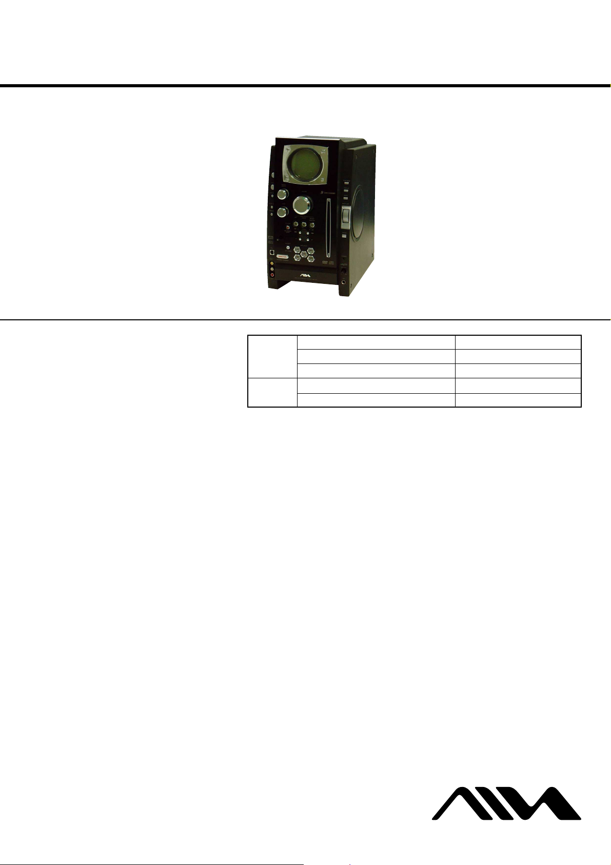
CX-BK7
SERVICE MANUAL
Ver 1.1 2004.02
• CX-BK7 is the amplifier, disc player, tape
deck and tuner section in BMZ-K7D.
This system incorporates Dolby* Digital, Dolby Pro
Logic (II) adaptive matrix surround decoder, and the
DTS** Digital Surround System.
*Manufactured under license from Dolby
Laboratories.
“Dolby”, “Pro Logic” and the double-D symbol are
trademarks of Dolby Laboratories.
**Manufactured under license from Digital Theater
Systems, Inc. “DTS” and “DTS Dig ita l S ur round”
are registered trademarks of Digital Theater
Systems, Inc.
US and foreign patents licensed from Dolby
Laboratories.
DVD
Section
Tape deck
Section
Model Name Using Similar Mechanism NEW
DVD Mechanism Type CDM69DV-DVBU16V
Optical Traverse Unit Name DBU-1
Model Name Using Similar Mechanism NEW
Tape Transport Mechanism Type CMAL1Z241A
SPECIFICATIONS
AEP Model
UK Model
E Model
Australian Model
Amplifier section
The following measured at AC 120, 127, 220, 240 V,
50/60 Hz
Rated Power Output at Stereo mode
Continuous RMS power output (reference)
Front speaker:
Center speaker: 50 watts (8 ohms at 1 kHz,
Surround speaker: 50 watts (8 ohms at 1 kHz,
Inputs
LINE IN AUDIO (phono jacks):
LINE IN VIDEO (phono jack):
MD (AUX) IN (phono jacks):
MIC (phone jack): sensitivity 1 mV,
150 + 150 watts
(6 ohms at 1 kHz, 10%
THD)
10% THD)
10% THD)
voltage 1.1V, impedance
47 kilohms
max. input level 1Vp-p,
unbalanced, Sync
negative, impedance
75 ohms
voltage 1.1V, impedance
47 kilohms
impedance 10 kilohms
Outputs
MD (AUX) OUT (phono jacks):
VIDEO OUT (phono jack):
S-VIDEO OUT (4-pin/mini-DIN jack):
COMPONENT VIDEO OUT:
PHONES (stereo mini jack):
Front spea ker: Use only the supplie d
Surround speaker: Use only the supplied
Center speaker: Use only the supplied
SUB WOOFER OUT: voltage 1 V,
voltage 500 mV,
impedance 4.7 kilohms
max. output level
1 Vp-p, unbalanced, Sync
negative, load impedance
75 ohms
Y: 1 Vp-p, unbalanced,
Sync negative,
C: 0.286 Vp-p, load
impedance 75 ohms
Y: 1 Vp-p, 75 ohm s
B
, PR: 0.7 Vp-p, 75 ohms
P
accepts headphones of
32 ohms or more
speaker SX-BK7
speaker SX-BK7R
speaker SX-BK7C
impedance 1 kilohm
Disc player section
System Compact disc and digital
audio and video system
Laser Semiconductor laser
(DVD: λ=657 nm,
CD: λ=793 nm)
Emission duration:
continuous
Frequency response DVD (PCM 48 kHz):
2 Hz − 22 kHz (±1 dB)
CD: 2 Hz − 20 kHz (±1 dB)
Video color system format
NTSC, PAL
OPTICAL DIGITAL OUT (Euro/UK, Russian models
only)
(Square optical connector jack, rear panel)
Wavelength 660 nm
Tape deck section
Recording system 4-track 2-channel stereo
Frequency response 100 − 10,000 Hz (±3 dB) ,
using Sony TYPE I ca ssette
– Continued on next page –
DVD DECK RECEIVER
9-961-333-02 Sony Corporation
2004B05-1 Home Audio Company
C 2004.02 Published by Sony Engineering Corporation
CX-BK7
Tune r se ction
FM stereo, FM/AM superheterodyne tu ner
FM tuner section
Tuning range
Russian model: 65.0 - 74.0 MHz
Other models: 87.5 -108.0 MHz
Antenna FM lead antenna
Antenna terminals 75 ohm unba la nc e d
Intermediate frequency 10.7 MHz
AM tuner section
Tuning range
Latin American models: 530 − 1,710 kHz
Saudi Arabian model: 531− 1,602 kHz (with the
Other models: 531 − 1,602 kHz (with the
Antenna AM loop antenna
Antenna terminals External antenna terminal
Intermediate frequency 450 kHz
General
Power requirements
Euro/UK, Russian models: 230 V AC, 50/60 Hz
Australian model: 230 − 240 V AC, 50/60 Hz
Saudi Arabian model: 120 − 127 V, 220 V AC,
Other models: 120 V, 220 V or 230 −
Power consumption
Dimensions (w/h/d)
Mass
87.5 - 108.0 MHz
(with the interval set at
10 kHz)
531 − 1,710 kHz
(with the interval set at
9k Hz)
interval set at 9 kH
interval set at 9 kHz)
530 − 1,710 kHz (with the
interval set at 10 kHz)
50/60 Hz
Adjustable with voltage
selector
240 V A C , 50/60 Hz
Adjustable with voltage
selector
250 watts
0.4 watts (in ECO MODE)
Approx. 211 × 379 ×
419 mm
Approx. 10.8 kg
z)
Notes on chip component replacement
•Never reuse a disconnected chip component.
• Notice that the minus side of a tantalum capacitor may be damaged by heat.
Flexible Circuit Board Repairing
•Keep the temperature of the soldering iron around 270 ˚C during repairing.
• Do not touch the soldering iron on the same conductor of the
circuit board (within 3 times).
• Be careful not to apply force on the conductor when soldering
or unsoldering.
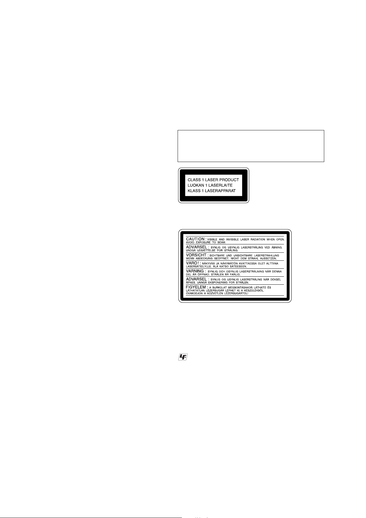
CAUTION
Use of controls or adjustments or performance of procedures
other than those specified herein may result in hazardous radiation exposure.
This appliance is
classified as a CLASS 1
LASER product. This
label is located on the
rear exterior.
The following caution label is located inside the
apparatus.
Design and specifications are subject to change
without notice.
SAFETY-RELATED COMPONENT WARNING!!
COMPONENTS IDENTIFIED BY MARK 0 OR DOTTED
LINE WITH MARK 0 ON THE SCHEMATIC DIAGRAMS
AND IN THE PARTS LIST ARE CRITICAL TO SAFE
OPERATION. REPLACE THESE COMPONENTS WITH
SONY PARTS WHOSE PART NUMBERS APPEAR AS
SHOWN IN THIS MANUAL OR IN SUPPLEMENTS PUBLISHED BY SONY.
UNLEADED SOLDER
Boards requiring use of unleaded solder are printed with the leadfree mark (LF) indicating the solder contains no lead.
(Caution: Some printed circuit boards may not come printed with
the lead free mark due to their particular size)
: LEAD FREE MARK
Unleaded solder has the following characteristics.
• Unleaded solder melts at a temperature about 40 ˚C higher than
ordinary solder.
Ordinary soldering irons can be used but the iron tip has to be
applied to the solder joint for a slightly longer time.
Soldering irons using a temperature regulator should be set to
about 350 ˚C.
Caution: The printed pattern (copper foil) may peel away if the
heated tip is applied for too long, so be careful!
• Strong viscosity
Unleaded solder is more viscou-s (sticky, less prone to flow)
than ordinary solder so use caution not to let solder bridges occur such as on IC pins, etc.
• Usable with ordinary solder
It is best to use only unleaded solder but unleaded solder may
also be added to ordinary solder.
2
CX-BK7
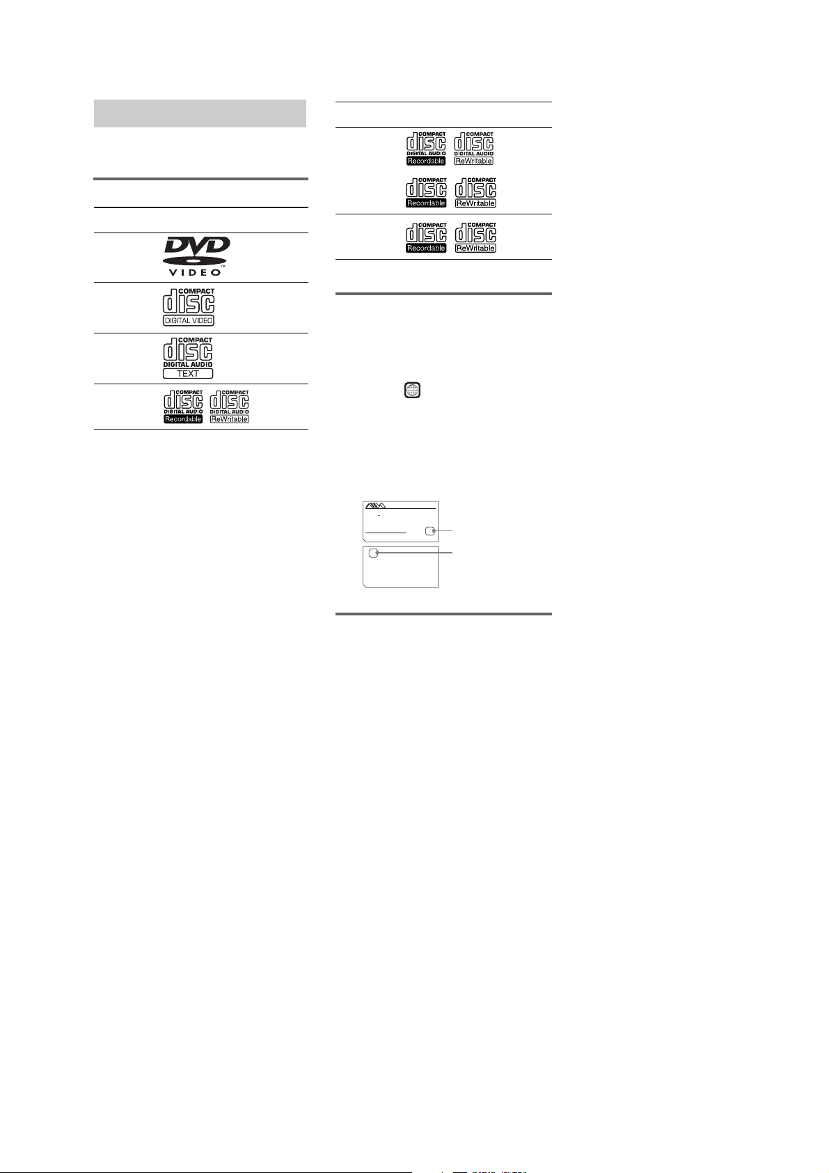
Playable discs
You can play back the following discs on this
system. Other discs cannot be played back.
List of playable discs
Format of
discs
DVD VIDEOs Audio +
VIDEO CDs Audio +
Audio CDs Audio
CD-R/CD-RW
(audio data)
Disc logo Contents
Video
Video
Audio
Format of
discs
CD-R/CD-RW
(MP3 files)
CD-R/CD-RW
(JPEG files)
The “DVD VIDEO” logo is a trademark.
Disc logo Contents
Audio
Video
Region code of DVDs you can
play on this system
Your system has a region code printed on the
back of the unit and will only play DVDs labeled
with identical region code.
DVDs labeled will also be played on this
ALL
system.
If you try to play any other DVD, the message
“Playback prohibited by area limitations.” will
appear on the TV screen. Depending on the
DVD, no region code indication may be labeled
even though playing the DVD is prohibited by
area restrictions.
MODEL NO. CX-BK7
DVD DECK RECEIVER
AC:230V 50/60Hz W
SERIAL NO.AREA
SERIAL NO.
Sony Corporation
X
4-249-187-2 CEL/CEK
Region code
X
(Euro/UK, Russian models)
Region code
(except Euro/UK, Russian
models)
Discs that this system cannot
play
•CD-ROMs (except for extension “.MP3,”
“.JPG,” or “.JPEG”)
•CD-Rs/CD-RWs other than those recorded in
the following formats:
–music CD format
–video CD format
–MP3/JPEG format that conforms to
ISO9660*
Session*
1
Level 1/Level 2, Joliet or Multi
2
•Data part of CD-Extras
•Super Audio CDs
•Progressive JPEG format files cannot be
played on this system.
• DVD-RWs in VR mode (DVD-RWs created
in VR (Video Recording) mode allow the
contents to be programed or edited.)
• DVD-ROMs
• DVD Audio discs
•A DVD with a different region code.
•Audio tracks in MP3PRO format.
•A disc that has a non-standard shape (e.g.,
card, heart).
•A disc with paper or stickers on it.
•A disc that has the adhesive, cellophane tape,
or a sticker still left on it.
*1
ISO9660 Format
The most common international standard for the
logical format of files and folders on a CD-ROM.
There are severa l specification levels. In Leve l 1, file
names must be in the 8.3 format (no more than eight
characters in the name, no more than three characters
in the extension “.MP3” or “.JPG”) and in capital
letters. Folder names can be no longer than eight
characters. There can be no more than eight nested
folder levels. Level 2 sp ecifications allow file names
and folder names up to 31 characters long. Each
folder can have up to 8 trees.
For Joliet in the expansion format (file and folder
names can have up to 64 characters) m ake sure of the
contents of the writing software, etc.
*2
Multi Session
This is a recording method that enables adding of
data using the Trac k-At-Once method. Conventional
CDs begin at a CD control area called the Lead-in
and end at an area called Lead-out. A Multi Session
CD is a CD having multiple sessions, with each
segment from Lead-in to Lead-out regarded as a
single session.
CD-Extra: This format records audio (audio CD
data) on the tracks in se ssion 1 and data on the tracks
in session 2.
3

CX-BK7
Note on playback operations
of DVDs and VIDEO CDs
Some playback operations of DVDs and VIDEO
CDs may be intentionally set by software
producers. Since this system plays DVDs and
VIDEO CDs according to the disc contents the
software producers designed, some playback
features may not be available. Also, refer to the
instructions supplied with the DVDs or VIDEO
CDs.
Copyrights
This product incorporates copyright protection
technology that is protected by U.S. patents and
other intellectual property rights. Use of this
copyright protection technology must be
authorized by Macrovision, and is intended for
home and other limited viewing uses only unless
otherwise authorized by Macrovision. Reverse
engineering or disassembly is prohibited.
Music discs encoded with
copyright prot ec ti on
technologies
This product is designed to playback discs that
conform to the Compact Disc (CD) standard.
Recently, various music discs encoded with
copyright protection technologies are marketed
by some record companies. Please be aware that
among those discs, there are some that do not
conform to the CD standard and may not be
playable by this product.
Cautions when playing a disc
that is recorded in Multi
Session
•This system can play Multi Session CDs when
an MP3 audio track is contained in the first
session. Any subsequent MP3 audio tracks
recorded in later sessions can also be played
back.
•This system can play Multi Session CDs when
a JPEG image file is contained in the first
session. Any subsequent JPEG image files
recorded in later sessions can also be played
back.
•If audio tracks and images in music CD
format or video CD format are recorded in the
first session, only the first session will be
played back.
Notes on discs
•This system can play CD-R/CD-RW discs
edited by the user. However, note that
playback of some discs may not be possible
depending on the recording device used for
recording or the disc condition.
•Discs recorded on CD-R/CD-RW drives may
not be played back because of scratches, dirt,
recording condition or the driver’s
characteristics.
•CD-R and CD-RW discs that have not been
correctly finalized (processing to allow play
by a normal CD player) cannot be played.
•CD-R and CD-RW discs recorded in multisession that have not ended by “closing the
session” are not supported.
•The system may be unable to play MP3/JPEG
format files that do not have the extender
“.MP3,” “.JPG,” or “.JPEG.”
•Attempting to play non-MP3/JPEG format
files that have the extender “.MP3,” “.JPG,”
or “.JPEG” may result in noise or
malfunction. Playback is possible up to 8
levels.
•With formats other than ISO9660 level 1 and
2, folder names or file names may not be
displayed correctly.
•The following discs take a longer time to start
playback:
–a disc recorded with a complicated tree
structure.
–a disc recorded in Multi Session.
–a disc to which data can be added (non-
finalized disc).
•Some CD-Rs, CD-RWs, DVD-Rs or DVDRWs (in video mode) (DVD-RWs created in
video mode have the same format as a DVD
VIDEO) cannot be played on this system
depending upon the recording quality or
physical condition of the disc, or the
characteristics of the recording device.
Furthermore, the disc will not play if it has not
been correctly finalized. For more
information, see the operating instructions for
the recording device.
•A disc recorded in packet write format cannot
be played.
4

TABLE OF CONTENTS
CX-BK7
1. SERVICING NOTES ................................................ 6
2. GENERAL ................................................................... 8
3. DISASSEMBLY
3-1. Disassembly Flow ........................................................... 9
3-2. Panel ................................................................................ 10
3-3. Top Panel Block .............................................................. 10
3-4. Front Panel Assy ............................................................. 11
3-5. Shield Plate...................................................................... 11
3-6. MAIN Board ................................................................... 12
3-7. Rear Cover....................................................................... 12
3-8. Tuner (FM/AM) .............................................................. 13
3-9. SP Board.......................................................................... 13
3-10. ACDC Board, Power Transformer.................................. 14
3-11. FRONT AMP/SUR AMP Board ..................................... 14
3-12. DVD Mechanism Deck (CDM69DV-DVBU16V)......... 15
3-13. Signal Cassette Mechanism ............................................ 15
3-14. Optical Pick-Up Section (DVBU16V) ........................... 16
3-15. Optical Traverse Unit (Service Assy , DBU-1) ............... 16
3-16. SW (1) Board, SW (2) Board, SW (3) Board,
SW (4) Board, Bracket (TOP) Assy ............................... 17
3-17. RELAY Board ................................................................. 17
3-18. Motor (Stocker) Assy (Stocker) (M761) ........................ 18
3-19. Motor (Roller) Assy (Roller) (M781)............................. 18
3-20. Motor (Mode) Assy (Mode) (M771) .............................. 19
3-21. Rubber Roller (Slider) Assy ........................................... 19
3-22. Timing Belt (Front/Rear) ................................................ 20
3-23. Cam (Gear) ...................................................................... 20
3-24. SENSOR Board ............................................................... 21
4. ASSEMBLY
4-1. How to Install the Cam (Eject Lock).............................. 22
4-2. How to Install the Cam (Gear)........................................ 22
4-3. How to Install the Gear (Mode 2)................................... 23
4-4. How to Install the Gear (Mode Cam) ............................. 23
4-5. How to Install the Rotary Encorder (S702),
Gear (Stocker Communication) ...................................... 24
4-6. How to Install the Cam (Stocker U/D) ........................... 24
4-7. How to Install the Stocker Assy ..................................... 25
4-8. Phase Adjustment Between Pinions (Slider)
and Slider-1 to 5 (L/R).................................................... 26
5. TEST MODE.............................................................. 27
6. ELECTRICAL ADJUSTMENTS
DVD Section ................................................................... 37
DECK Section ................................................................. 37
7. DIAGRAMS
7-1. Block Diagram – RF SERVO Section – ......................... 38
7-2. Block Diagram – CHANGER/VIDEO Section – .......... 39
7-3. Block Diagram – TUNER/TAPE/USB Section – .......... 40
7-4. Block Diagram – AMP Section – ................................... 41
7-5. Block Diagram
– PANEL/POWER SUPPLY Section – .......................... 42
7-6. Note for Printed Wiring Boards
and Schematic Diagrams ................................................ 43
7-7. Printed Wiring Board – RF Board – ............................... 44
7-8. Schematic Diagram – RF Board –.................................. 45
7-9. Printed Wiring Boards – CHANGER Section –............. 46
7-10. Schematic Diagram – CHANGER Section – ................. 47
7-11. Printed Wiring Board
– MB03 Board (Side A) –............................................... 48
7-12. Printed Wiring Board
– MB03 Board (Side B) – ............................................... 49
7-13. Schematic Diagram – MB03 Board (1/8) – ................... 50
7-14. Schematic Diagram – MB03 Board (2/8) – ................... 51
7-15. Schematic Diagram – MB03 Board (3/8) – ................... 52
7-16. Schematic Diagram – MB03 Board (4/8) – ................... 53
7-17. Schematic Diagram – MB03 Board (5/8) – ................... 54
7-18. Schematic Diagram – MB03 Board (6/8) – ................... 55
7-19. Schematic Diagram – MB03 Board (7/8) – ................... 56
7-20. Schematic Diagram – MB03 Board (8/8) – ................... 57
7-21. Printed Wiring Board – VIDEO Board – ........................ 58
7-22. Schematic Diagr am – VIDEO Board – .......................... 59
7-23. Printed Wiring Board – DECK Board – ......................... 60
7-24. Schematic Diagram – DECK Board – ............................ 61
7-25. Printed Wiring Board – USB AUX Board –................... 62
7-26. Schematic Diagr am – USB AUX Board –...................... 63
7-27. Printed Wiring Board – MIC Board – ............................ 64
7-28. Schematic Diagram – MIC Board – ............................... 65
7-29. Schematic Diagram – MAIN Board (1/4) – ................... 66
7-30. Schematic Diagram – MAIN Board (2/4) – ................... 67
7-31. Schematic Diagram – MAIN Board (3/4) – ................... 68
7-32. Schematic Diagram – MAIN Board (4/4) – ................... 69
7-33. Printed Wiring Board – MAIN Board – ......................... 70
7-34. Printed Wiring Board – FRONT AMP Board – ............. 71
7-35. Schematic Diagr am – FRONT AMP Board (1/2) – ....... 72
7-36. Schematic Diagr am – FRONT AMP Board (2/2) – ....... 73
7-37. Printed Wiring Board – SURAMP Board – ................... 74
7-38. Schematic Diagram – SURAMP Board – ...................... 75
7-39. Printed Wiring Boards
– HEADPHONE/SP Boards – ........................................ 76
7-40. Schematic Diagrams
– HEADPHONE/SP Boards – ........................................ 77
7-41. Printed Wiring Boards – PANEL Section (1/2) – .......... 78
7-42. Schematic Diagr am – PANEL Section (1/2) –............... 79
7-43. Printed Wiring Boards – PANEL Section (2/2) – .......... 80
7-44. Schematic Diagr am – PANEL Section (2/2) –............... 81
7-45. Printed Wiring Boards
– ACDC Board (Except Saudi Arabia model) –............. 82
7-46. Schematic Diagram
– ACDC Board (Except Saudi Arabia model) –............. 83
7-47. Printed Wiring Board
– ACDC Board (Saudi Arabia model) –......................... 84
7-48. Schematic Diagram
– ACDC Board (Saudi Arabia model) –......................... 85
7-49. Printed Wiring Board – PT96 Board – ........................... 86
7-50. Schematic Diagram – PT96 Board – .............................. 87
7-51. IC Pin Function Description ........................................... 98
8. EXPLODED VIEWS
8-1. Side Panel Section.......................................................... 114
8-2. Top Panel Section...........................................................115
8-3. Front Block-1
(KEY LED RMC/USB AUX Board Section)................ 116
8-4. Front Block-2
(LCD VOL Board Section) ............................................ 117
8-5. Front Block-3
(Cabinet Front Assy Section)......................................... 118
8-6. MAIN/ACDC Board Section .........................................119
8-7. MB03 Board Section...................................................... 120
8-8. Power Transformer Section ........................................... 121
8-9. FR ONT AMP/SUR AMP Board Section....................... 122
8-10. DVD Mechanism Deck Section-1
(CDM69DV-DVBU16V) ............................................... 123
8-11. DVD Mechanism Deck Section-2
(CDM69DV-DVBU16V) ............................................... 124
8-12. DVD Mechanism Deck Section-3
(CDM69DV-DVBU16V) ............................................... 125
8-13. DVD Mechanism Deck Section-4
(CDM69DV-DVBU16V) ............................................... 126
8-14. DVD Mechanism Deck Section-5
(CDM69DV-DVBU16V) ............................................... 127
8-15. DVD Mechanism Deck Section-6
(CDM69DV-DVBU16V) ............................................... 128
8-16. Optical Traverse Unit Section (DVBU16V).................. 129
9. ELECTRICAL PARTS LIST .............................. 130
5
CX-BK7
SECTION 1
SERVICING NOTES
NOTES ON HANDLING THE OPTICAL PICK-UP
BLOCK OR BASE UNIT
The laser diode in the optical pick-up block may suffer electrostatic break-down because of the potential difference generated
by the charged electrostatic load, etc. on clothing and the human
body.
During repair, pay attention to electrostatic break-down and also
use the procedure in the printed matter which is included in the
repair parts.
The flexible board is easily damaged and should be handled with
care.
NOTES ON LASER DIODE EMISSION CHECK
The laser beam on this model is concentrated so as to be focused
on the disc reflective surface by the objective lens in the optical
pick-up block. Therefore, when checking the laser diode emission, observe from more than 30 cm away from the objectiv e lens.
RELEASING THE DISC LOCK
The disc lock function for the antitheft of an demonstration
disc in the store is equipped.
Releasing Procedure :
While pressing the [ENTER] key , press the Z key for 5 seconds.
The message “UNLOCKED” is displayed and the disc is unlocked.
Note: When “LOCKED” is displayed, the disc lock is not released by
turning power on/off with the I/1 key.
• MODEL IDENTIFICATION
– Rear Cover –
PART No.
MODEL PART No.
Chilean and Peruvian models 4-249-187-1
AEP and UK models 4-249-187-2
Mexican model 4-249-187-3
Saudi Arabia model 4-249-187-4
Singapore and Malaysia models 4-249-187-5
Australian model 4-249-187-6
CIS model 4-249-187-7
[]
[]
[]
[]
[]
[]
[]
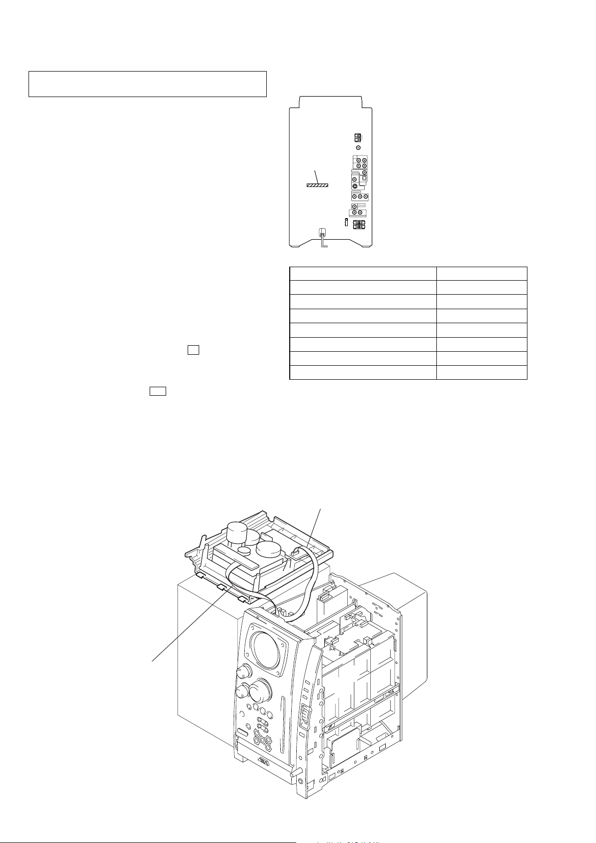
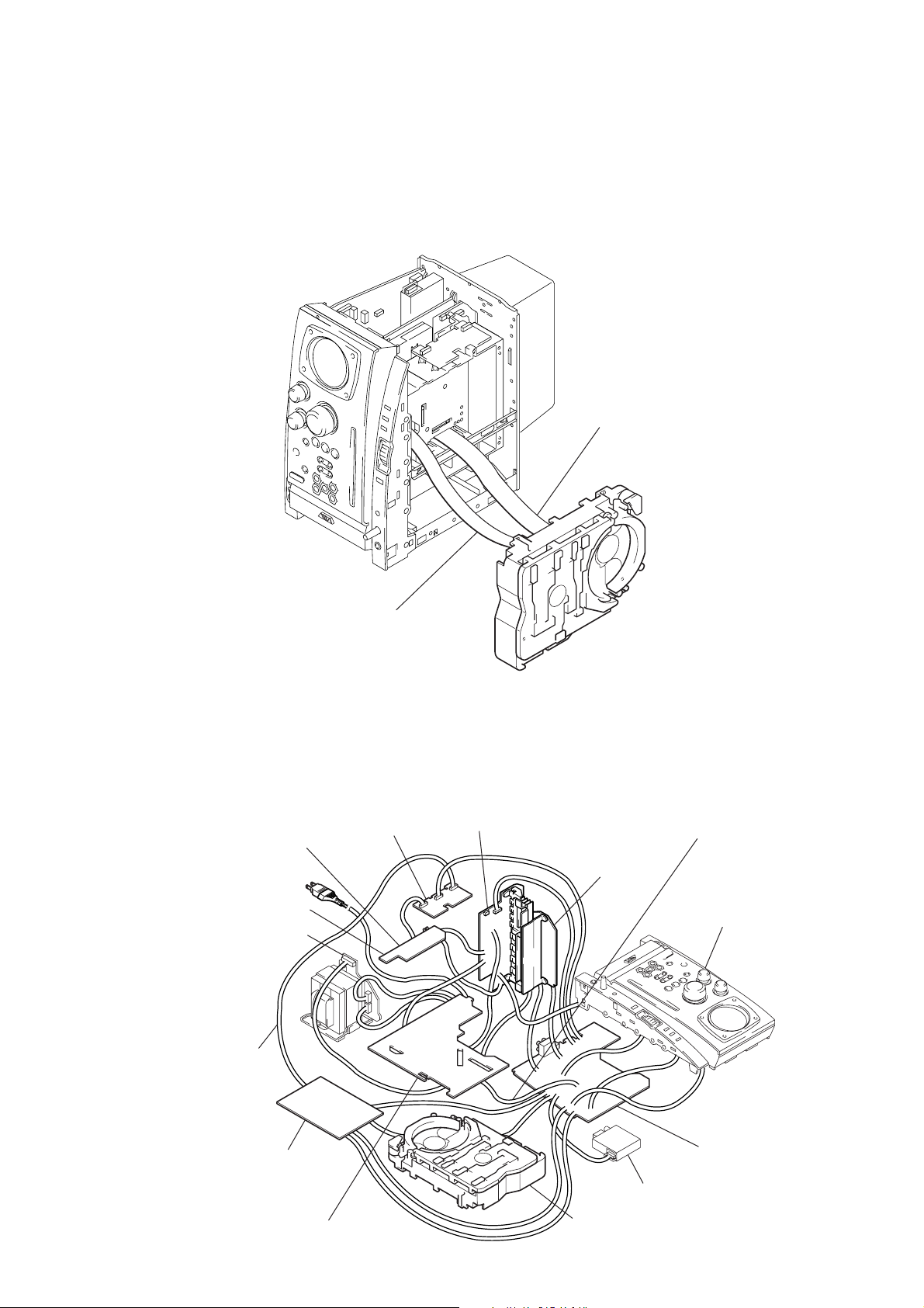
SERVICE POSITION
– Tape mechanism deck –
Connect the wire (flat type) (8 core)
to the main board (CN903) and
the mechanism deck.
Connect the wire (flat type) (11 core)
to the deck board (CN008) and the main board (CN009).
6
CX-BK7
– DVD mechanism deck –
• In checking the DVD mechanism deck section, prepare two extension jigs (Part No. J-2501-103-A: 1mm Pitch, 29 cores, Length
300mm/Part No. J-2501-248-A: 1mm Pitch, 27 cores, Length 300mm).
Note: The DVD mechanism deck of this model is a vertical type and putting it vertically as shown in the figure is the standard position.
When checking signals such as RF waveforms, operate it with the DVD mechanism deck in the standard position as shown below.
Connect the extension jig (J-2501-248-A)
to the relay board (CN201) and
the main board (CN901).
Connect the extension jig (J-2501-103-A)
to the RF board (CN002) and
the MBO3 board (CN501).
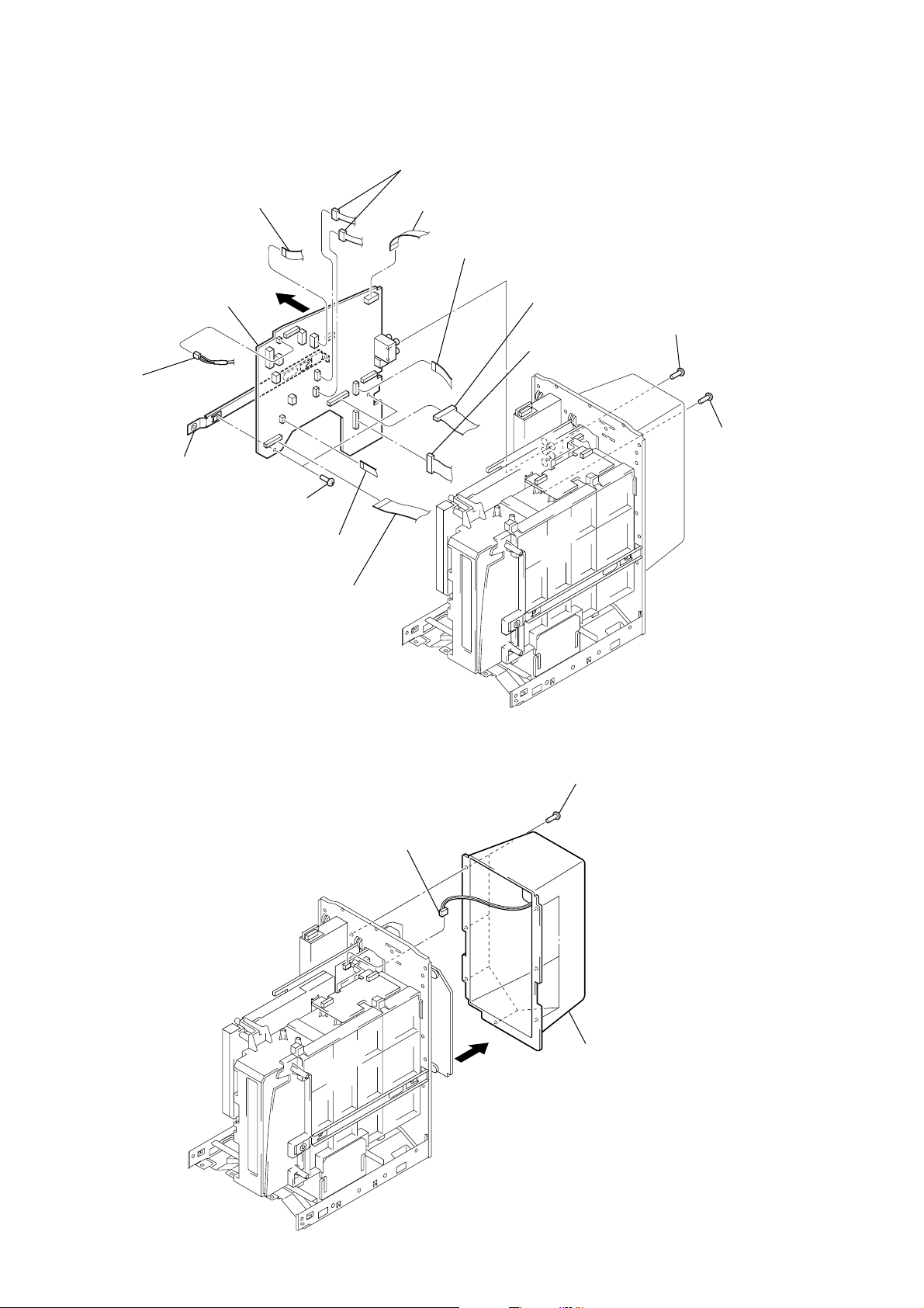
– MAIN board, ACDC board and MB03 board –
• For connecting the DVD mechanism deck, prepare three extension jigs. (Refer to “– DVD mechanism deck –”)
• In checking the MAIN/ACDC/MB03 boards, prepare three e xtension jigs (Part No. J-2501-231-A: 1mm Pitch, 15 cores, Length 300mm/
Part No. J-2501-243-A: 1mm Pitch, 17 cores, Length 300mm/Part No. J-2501-265-A: 4 pin, Length 300mm).
Connect the extension jig
(J-2501-231-A) to the video
board (CN802) and the SP
board (CN312).
SP board
PT96 board
Connect the extension jig
(J-2501-243-A) to the video
board (CN801) and the MB03
board (CN105).
video board
front AMP board
SURAMP board
Connect the extension jig
(J-2501-265-A) to the ACDC
board (CN004) and the main
board (CN007).
front panel section
MB03 board
ACDC board
main board
tuner unit
DVD mechanism deck
7
CX-BK7
SOUND FIELD
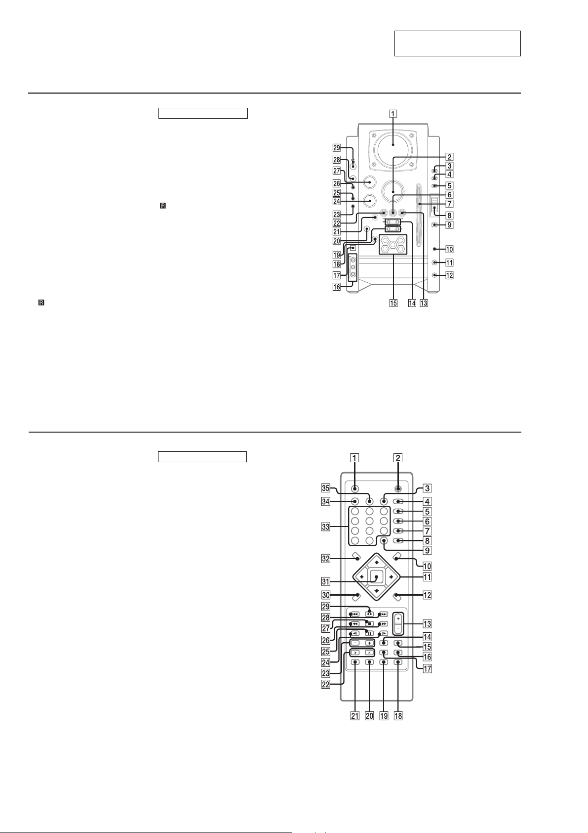
• LOCATION OF CONTROLS
Main unit
1 Display window
2 VOLUME control
3 PLAY MODE
4 DISPLAY
4 RDS
5 MODE
6 TUNER PRESET CLEAR
7 Disc slot
8 MULTI JOG
9 ENTER
q; PHONES jack
qa MIC LEVEL
qs MIC jack
qd SELECT DIRECTION
nN
qf TUNING − ./m
qf TUNING + M/>
qg DISC SELECT
qh LINE IN
qj USB jack
qk Z EJECT/DISC CHANGE
ql ALBUM/PLAY LIST +/−
w;
wa CD SYNC
wa REC PAUSE/START
ws TUNER PRESET SET
wd i-Bass
wf BASS
wg SOUND FIELD
wh TUNER/BAND
wj TREBLE/MIDDLE
wk FUNCTION
wl [/1 (power)
*1
*1
(Remote sensor)
BUTTON DESCRIPTIONS
[/1 (power) wl
X (pause) ws
Z (eject) qk
x (stop) 6
M/> (fast forward/
TUNING +) qf
nN SELECT DIRECTION
qd
./m (rewind/TUNING −)
qf
(Remote sensor) w;
*1
(except Euro/UK models):
DISPLAY
(Euro/UK models):
RDS function
SECTION 2
GENERAL
This section is extracted from
instruction manual.
TREBLE /
MIDDLE
FUNCTION
TUNER/BAND
LINE IN
VIDEO
L
R
AUDIO
VOLUME
BASS
TUNER PRESET
CLEAR
SELECT
SET
DIRECTION
CD SYNC
TUNING
REC PAUSE/
START
ALUBAM/PLAY LIST
Z EJECT
DISC SELECT
1
4
DISC CHANGE
3
2
5
PLAY MODE
DISPLAY
MODE
ENTER
PHONES
MIC LEVEL
MIN
XAM
MIC
Remote control
1 FUNCTION
2 [/1
3 REPEAT
4 SOUND FIELD
5 AUDIO
6 SUBTITLE
7 ANGLE
8 DVD SETUP
9 DISC SKIP
q; DVD MENU
qa M/m/</,
qs DVD DISPLAY
qd VOL +/−
qf FM MODE
qg TUNER/BAND
qh ECHO
qj KARAOKE
qk CLEAR)
ql AMP MENU
w; CLOCK/TIMER SELECT
wa CLOCK/TIMER SET
ws KEY CONTROL
wd ALBUM +/−
wf SLOW −/+
wg X (pause)
wh TUNING −/+
wj x (stop)
wk PRESET −/PREV .
wk PRESET +/NEXT >
wl SELECT bB
e; O RETURN
ea ENTER
es DVD TOP MENU
ed Number buttons
ef DISPLAY
eg PLAY MODE
*
#/2
BUTTON DESCRIPTIONS
[/1 2
x (stop) wj
bB (SELECT) wl
X (pause) wg
M/m/</, qa
m (TUNING −) wh
M (TUNING +) wh
. (PRESET −/PREV) wk
> (PRESET +/NEXT) wk
t (SLOW —) wf
T (SLOW +) wf
#
(KEY CONTROL) ws
2
(KEY CONTROL) ws
*
Switches the active function: DVD,
USB, TAPE, TUNER, VIDEO, MD.
8
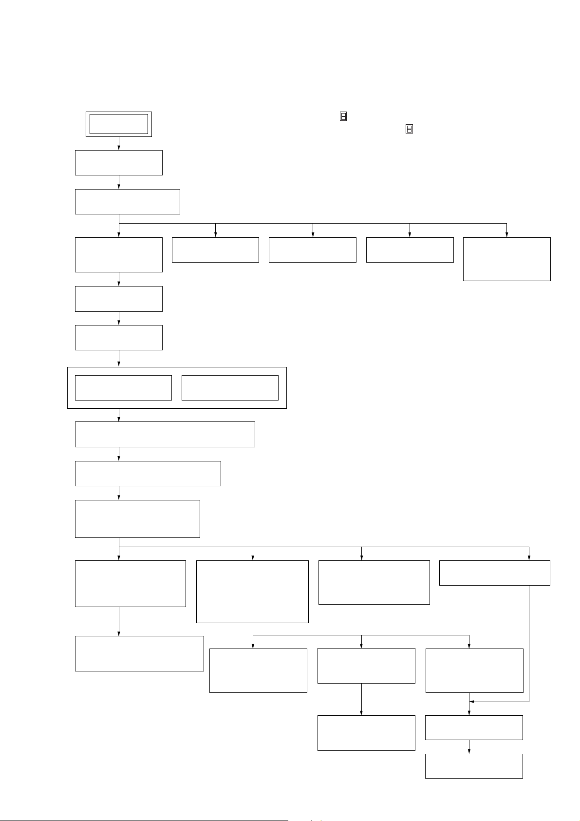
• This set can be disassembled in the order shown below.
3-1. DISASSEMBLY FLOW
CX-BK7
SECTION 3
DISASSEMBLY
SET
3-2. PANEL
(Page 10)
3-3. TOP PANEL BLOCK
(Page 10)
3-4. FRONT PANEL
ASSY
(Page 11)
3-5. SHIELD PLATE
(Page 11)
3-6. MAIN BOARD
(Page 12)
3-8. TUNER (FM/AM)
(Page 13)
Note 1: The process described in can be performed in any order.
Note 2: Without completing the process described in , the next process can not be performed.
Note 3: Tape deck is not loaded in US model.
3-7. REAR COVER
(Page 12)
3-9. SP BOARD
(Page 13)
3-8. TUNER (FM/AM)
(Page 13)
3-9. SP BOARD
(Page 13)
3-13. SIGNAL
CASSETTE
MECHANISM
(Page 15)
3-10. ACDC BOARD, POWER TRANSFORMER
(Page 14)
3-11. FRONT AMP/SURAMP BOARD
(Page 14)
3-12. DVD MECHANISM DECK
(CDM69DV-DVBU16V)
(Page 15)
3-14. OPTICAL PICK-UP
SECTION
(DVBU16V)
(Page 16)
3-15. OPTICAL TRAVERSE UNIT
(SERVICE ASSY, DBU-1)
(Page 16)
3-16. SW (1) BOARD,
SW (2) BOARD,
SW (3) BOARD,
SW (4) BOARD,
BRACKET (TOP) ASSY
(Page 17)
3-19. MOTOR (ROLLER)
ASSY (ROLLER)
(M781)
(Page 18)
3-18. MOTOR (STOCKER)
ASSY (STOCKER)
(M761)
(Page 18)
3-21. RUBBER ROLLER
(SLIDER) ASSY
(Page 19)
3-17. RELAY BOARD
(Page 17)
3-20. MOTOR (MODE)
ASSY (MODE)
(M771)
(Page 19)
3-22. TIMING BELT
(FRONT/REAR)
(Page 20)
3-23. CAM (GEAR)
(Page 20)
3-24. SENSOR BOARD
(Page 21)
9
CX-BK7
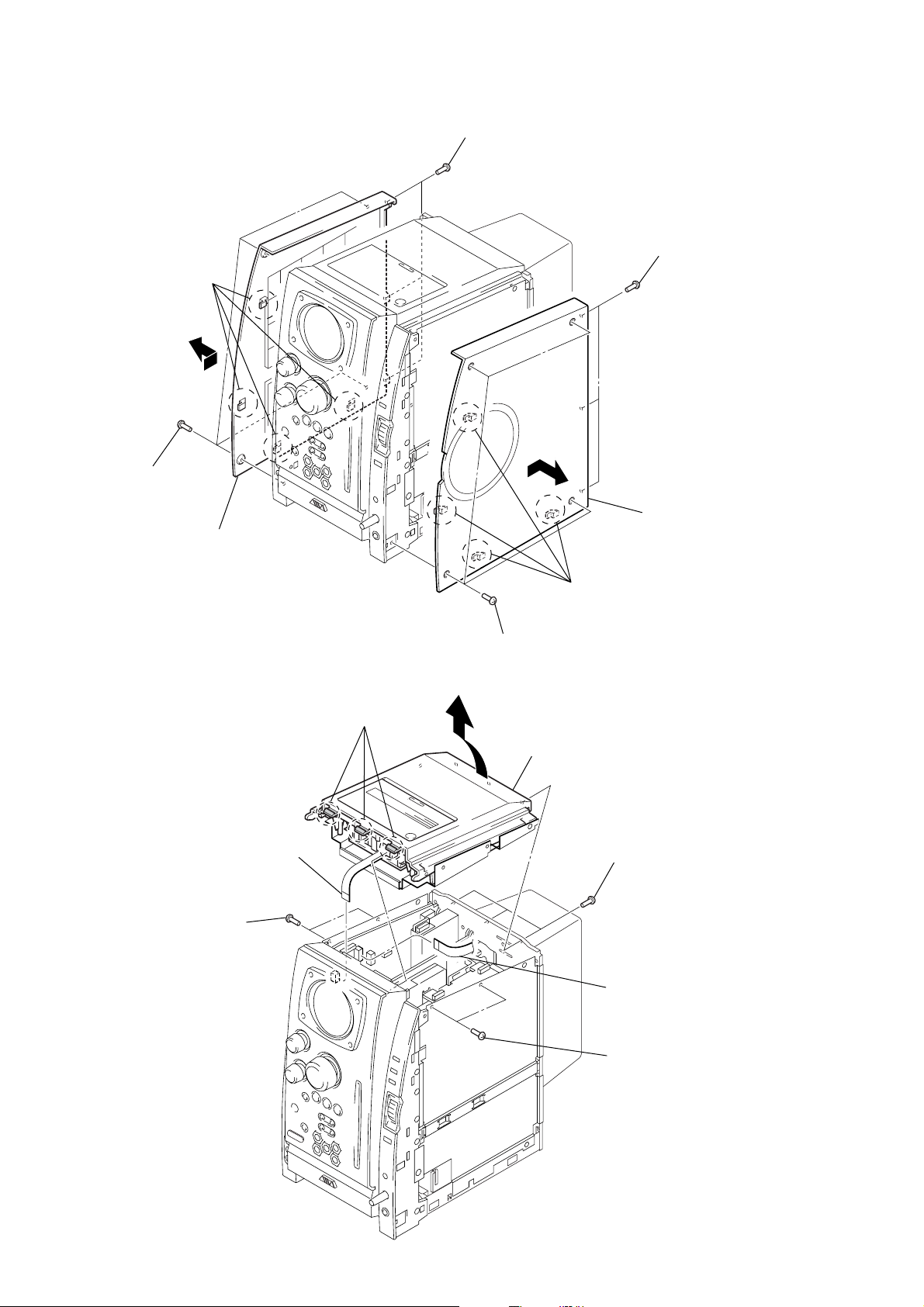
Note: Follow the disassembly procedure in the numerical order given.
3-2. PANEL
3
four claws
4
2
four screws
(BVTP3
×
10)
1
three screws
(BVTP3
×
10)
9
6
three screws
(BVTP3
right panel
0
×
10)
5
panel (left)
3-3. TOP PANEL BLOCK
4
wire (flat type) (8core)
(CN903)
1
two screws
×
(BVTP3
10)
2
three claws
3
7
four screws
(BVTP3
6
8
four claws
×
10)
top panel block
1
5
three screws
(BVTP3
wire (flat type) (11core)
(CN009)
×
10)
10
1
two screws
(BVTP3
×
10)

CX-BK7
)
3-4. FRONT PANEL ASSY
1
q;
front panel assy
6
two screws
(QT2+3-10)
2
wire (flat type) (17core)
(CN004)
wire (flat type) (19core)
(CN905)
8
two claws
9
connector (CN530)
3
wire (flat type) (5core)
(CN503)
4
two lead with connectors
5
five screws
(BVTP3
3-5. SHIELD PLATE
4
left shield plate
3
four screws
(BVTP3
×
10)
×
10)
7
four screws
(QT2+3-10)
2
shield plate (right
1
four screws
(BVTP3 × 10)
11
CX-BK7
)
3-6. MAIN BOARD
2
wire (flat type)
(11core: EXCEPT AEP, UK) (CN509)
(15core: AEP, UK) (CN508)
qf
q;
connector
(CN602)
qg
PC board
holder (main)
main board
qd
5
two screws
(BVTP3
×
6)
9
two connectors
(CN007, CN507)
1
wire (flat type) (11core)
(CN502)
6
wire (flat type) (11core)
(CN501)
7
connector
(CN007)
8
connector
(CN006)
3
two screws
(BVTP3
4
×
10)
screw
(BVTP3
×
10
3-7. REAR COVER
qs
wire (flat type) (7core)
(CN904)
wire (flat type) (27core)
qa
(CN901)
3
connector
(CN303)
1
seven screws
(BVTP3
×
10)
12
2
rear cover
4
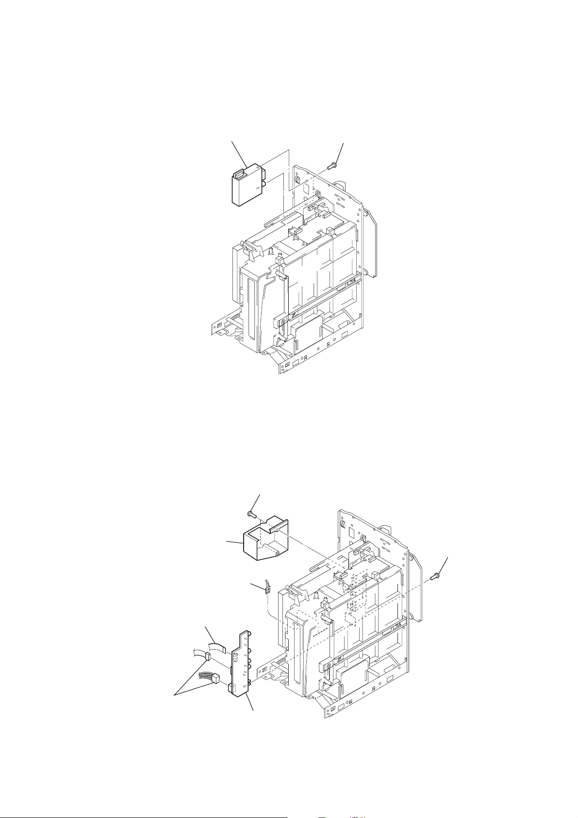
3-8. TUNER (FM/AM)
)
2
tuner (FM/AM)
1
two screws
(BVTP3
CX-BK7
×
8)
3-9. SP BOARD
5
two connectors
(CN503, CN511)
2
condenser cover
3
lead with connector
4
wire (flat type) (15core)
(CN512)
1
two screws
(BVTP3 × 12)
7
SP board
6
seven screws
(BVTP3 × 10
13
CX-BK7
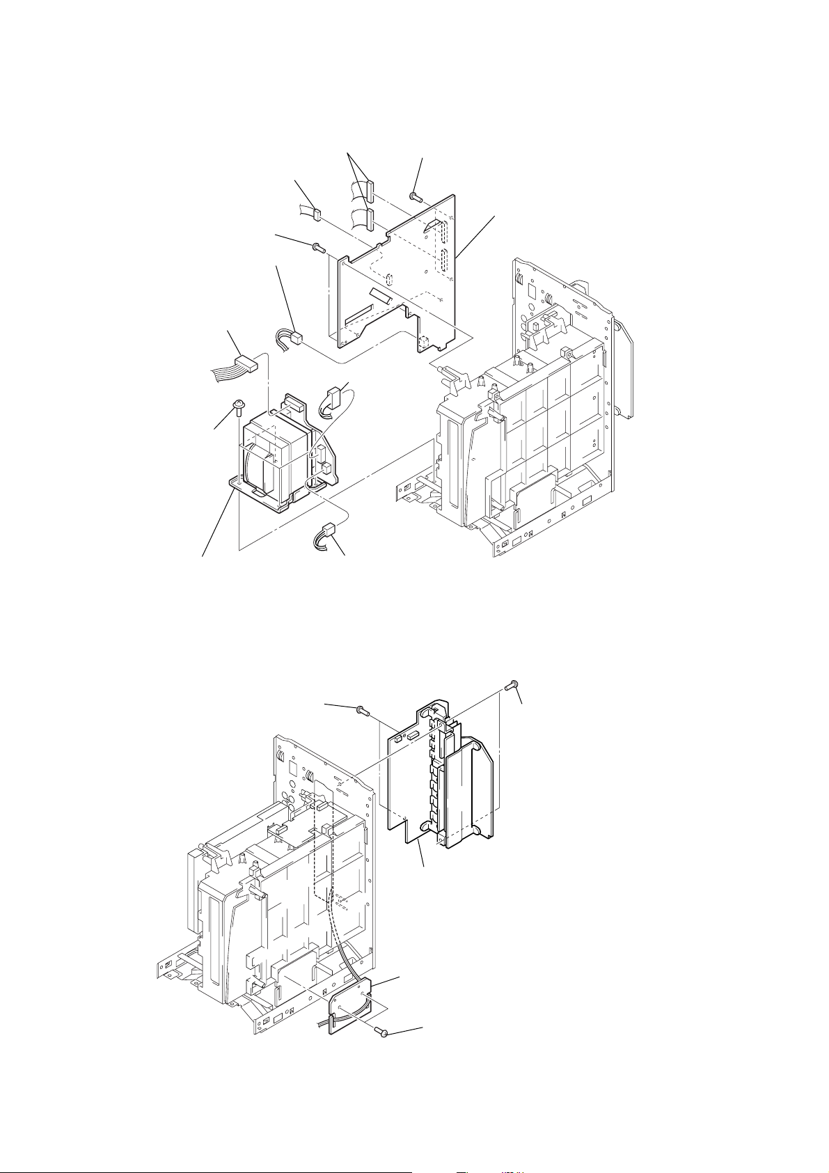
)
3-10. ACDC BOARD, POWER TRANSFORMER
1
two connectors
(CN003, CN005)
2
connector (CN006)
5
9
four screws
(ITC+4-8)
five screws
(BVTP3
3
connector (CN011)
7
connector
(CN014)
×
10)
8
connector
(CN008)
4
two screws
(BVTP3
×
10)
6
ACDC board
0
power transformer
3-11. FRONT AMP/SURAMP BOARD
4
two screws
(BVTP3 × 10)
8
connector
(CN007)
3
5
front AMP/SURAMP board
two screws
(BVTP3 × 10
14
2
CD support board
1
two screws
(BVTP3 × 10)
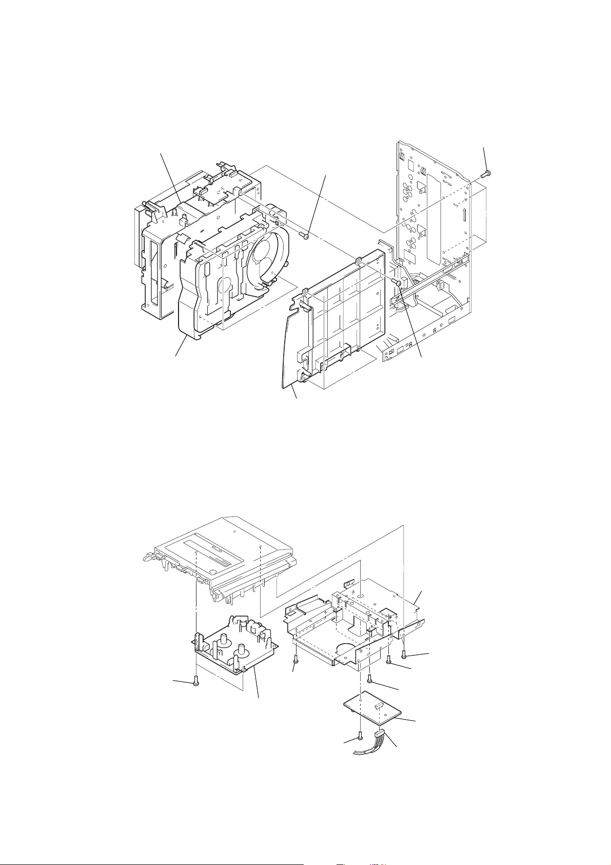
3-12. DVD MECHANISM DECK (CDM69DV-DVBU16V)
)
5
mecanical holder (disk)
4
four screws
(BVTP3
×
10)
1
four screws
(BVTP3
CX-BK7
×
10
6
DVD mechanism deck (CDM69DV-DVBU16V)
3-13. SIGNAL CASSETTE MECHANISM
9
two screws
(BVTP3
×
10)
q;
3
mechanical cover (disk)
7
four screws
(BVTP2.6
signal cassette mechanism
2
screw
(BVTP3
×
10)
2
four screws
(BVTP3
×
10)
8
shield plate (top)
5
five screws (BVTP3 × 10)
3
screw (BVTP3 × 10)
×
8)
6
two screws (BVTP3 × 10)
4
deck board
1
connector
(CN302)
15
CX-BK7
)
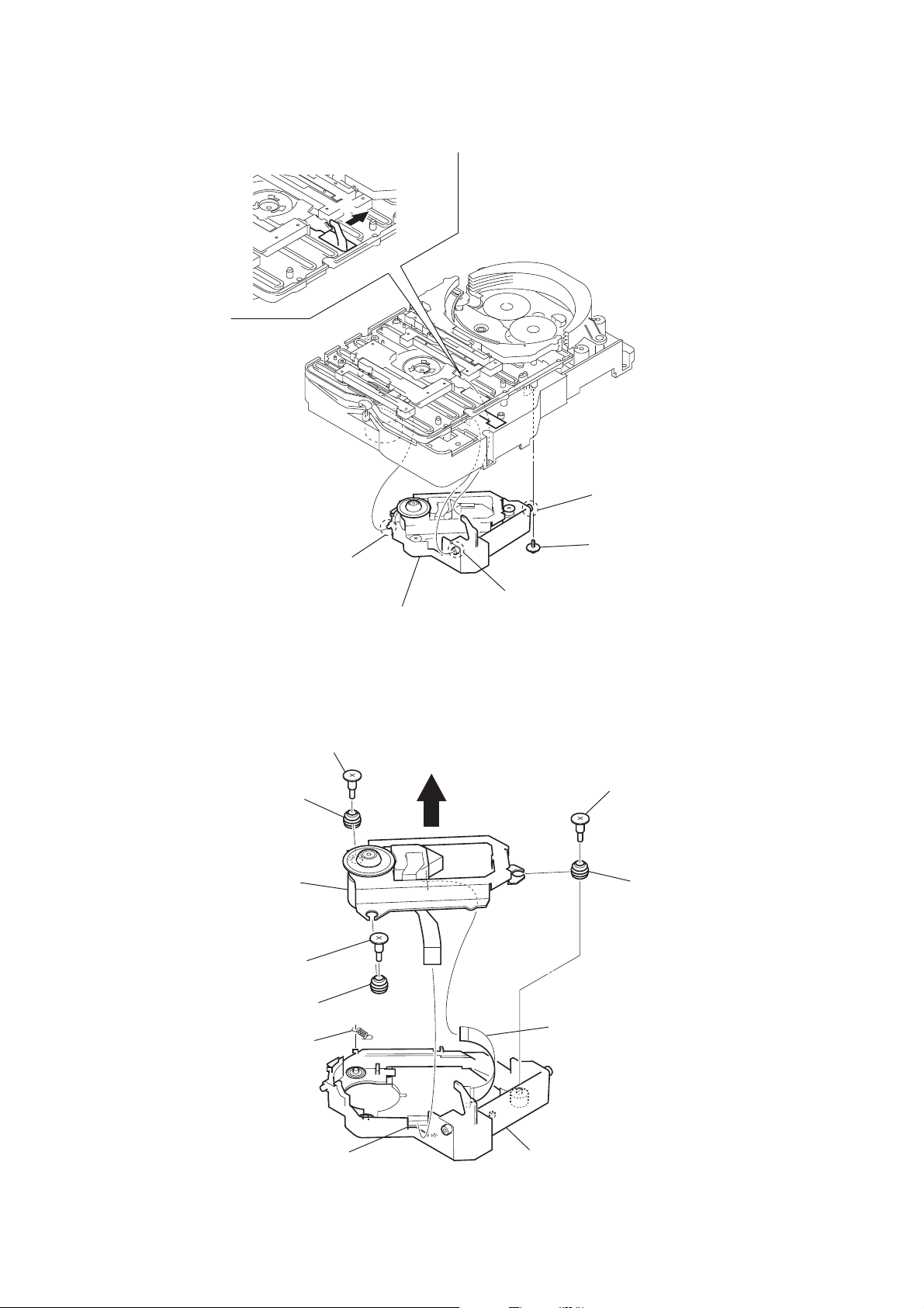
3-14. OPTICAL PICK-UP SECTION (DVBU16V)
2
5
boss
6
optical
pick-up section
(DVBU16V)
3-15. OPTICAL TRAVERSE UNIT (SERVICE ASSY, DBU-1)
1
step screw (M)
8
insulator
5
qa
optical traverse unit (service assy, DBU-1)
4
boss
3
boss
1
screw
(PTPWHM2.6
2
step screw (M)
9
insulator (RB)
16
3
4
tension spring
step screw (M)
q;
insulator
(DBU1)
6
connector
(CN003)
7
flexible board
holder (DBU1) section
CX-BK7
)
)
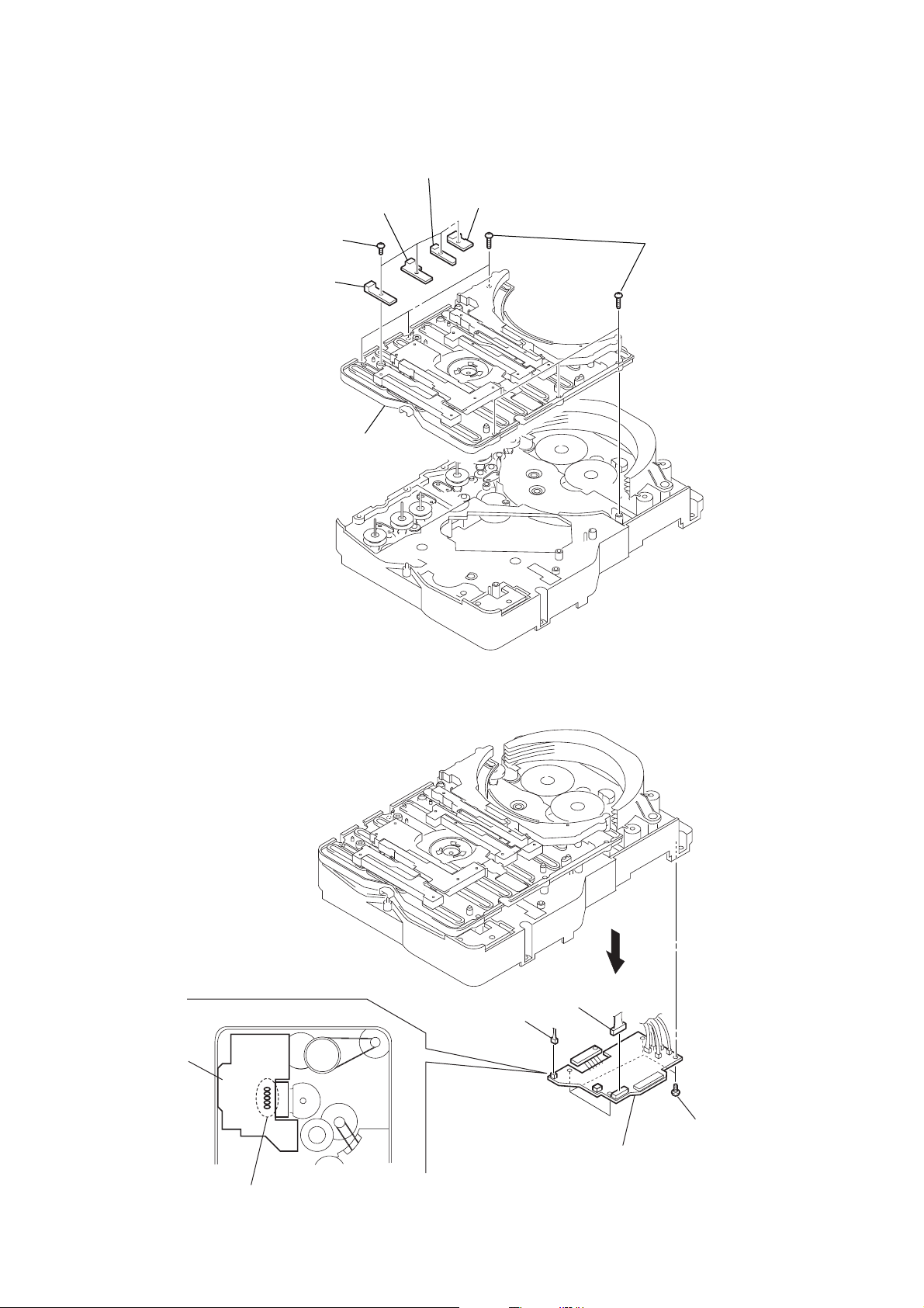
3-16. SW (1) BOARD, SW (2) BOARD, SW (3) BOARD, SW (4) BOARD, BRACKET (TOP) ASSY
4
SW (3) board
5
SW (4) board
6
six screws
(BVTP2.6
×
8
1
four
(BTP2.6
2
SW (1) board
7
3
SW (2) board
screws
×
6)
bracket (top) assy
3-17. RELAY BOARD
relay board
– bottom view –
5
connector
(CN703)
4
connector
(CN710)
3
6
relay board
2
four screws
(BVTP2.6
×
8
1
Remove five solders.
17
CX-BK7
)
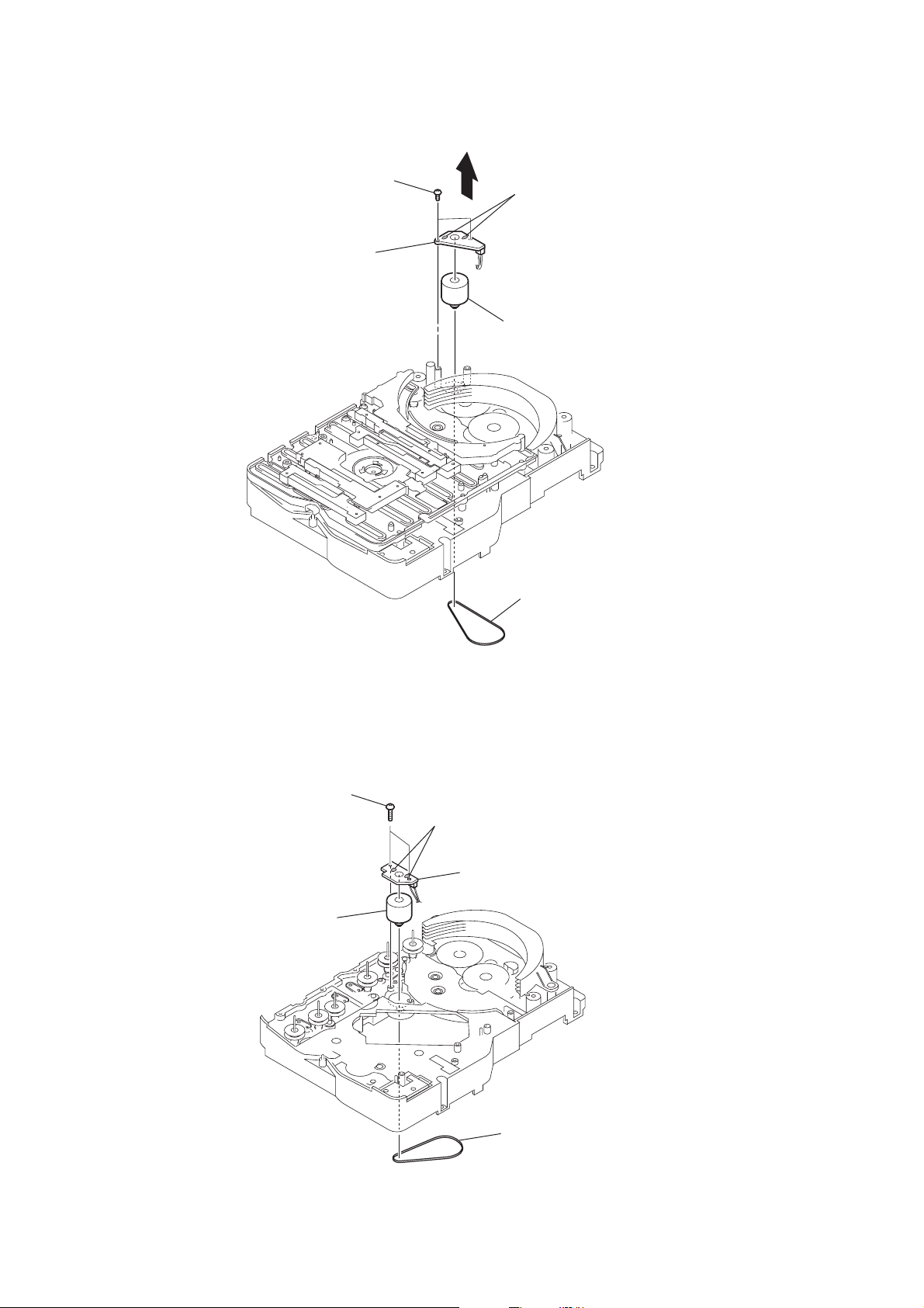
3-18. MOTOR (STOCKER) ASSY (STOCKER) (M761)
3
two screws
(BVTP2.6
5
stocker motor board
×
4
8)
2
Remove two solders.
6
motor (stocker) assy (stocker) (M761)
1
belt (stocker)
3-19. MOTOR (ROLLER) ASSY (ROLLER) (M781)
3
two screws
5
motor (roller) assy
(roller)(M781)
2
Remove two solders.
4
roller motor
1
board
belt (roller V
18
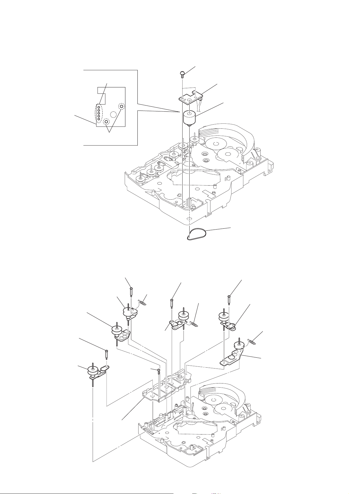
3-20. MOTOR (MODE) ASSY (MODE) (M771)
)
1
Remove five solders
of rotary encoder.
MODE MOTOR
board
2
Remove two solders
of motor (M771)
3
two screws
(BVTP2.6
×
8)
4
mode motor board
6
motor (mode) assy (mode) (M771)
CX-BK7
3-21. RUBBER ROLLER (SLIDER) ASSY
8
step screw
9
tension spring
(slider 2)
7
rubber roller
(slider 1) assy
×
8)
qs
qd
rubber roller
(slider 1) assy
qa
rubber roller
(slider 2) assy
step screw
0
rubber roller
(slider 4) assy
qf
screw
(BVTP2.6
5
step screw
6
tension spring
(base slider 4)
5
belt (mode V)
1
step screw
2
rubber roller
(slider S) assy
3
4
tension spring
(base slider 5
rubber roller
(slider 5) assy
qg
sub chassis
19
CX-BK7
)
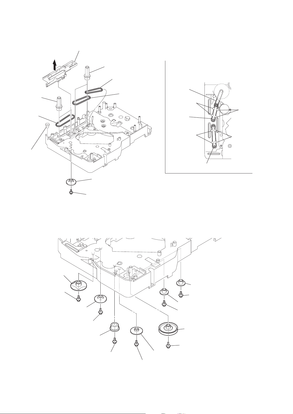
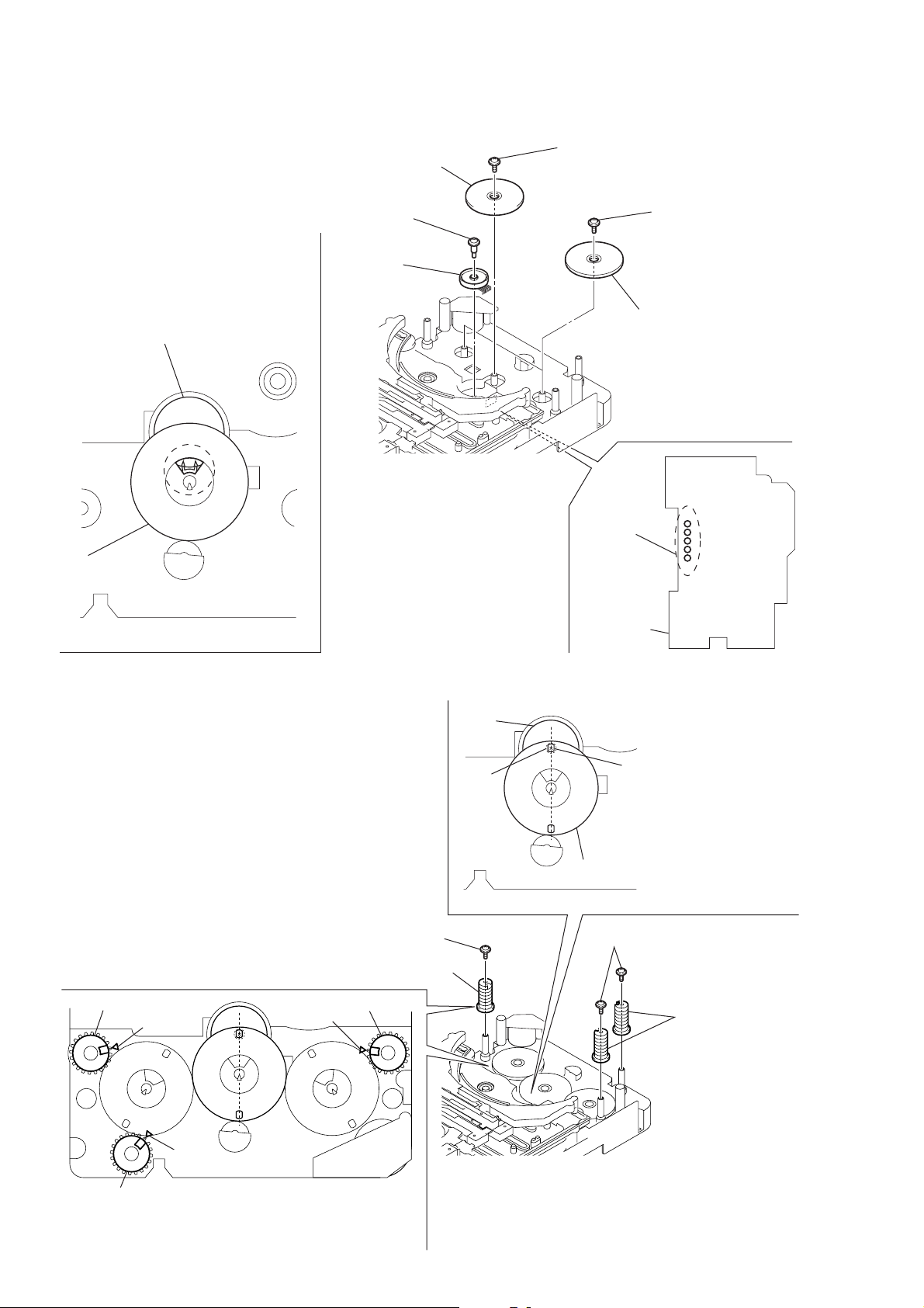
3-22. TIMING BELT (FRONT/REAR)
3
slider (mode cam) assy
5
two gears
(center)
6
timing belt
(front)
7
two gears (center)
8
timing belt (rear)
9
timing belt (rear)
When install three timing belts,
its pass under each claws.
timing belt
(rear)
claw
timing belt
(rear)
claw
4
gear
(timing)
3-23. CAM (GEAR)
qf
cam (gear)
: Note
2
gear (mode cam)
: Note
1
screw
(PTPWH2.6
×
claw
timing belt (front)
Note: Refer to assembly (Section 4)
8)
claw
20
qd
screw
qs
gear(mode cam)
qa
screw
(PTPWH2.6
0
Note: Refer to assembly
(Section 4).
×
8)
gear (mode C)
:Note
9
screw
(PTPWH2.6
6
gear (mode 5)
5
screw (PTPWH2.6 × 8
4
gear (mode 5)
3
screw (PTPWH2.6 × 8)
2
pulley
(mode deceleration)
1
screw(PTPWH2.6 × 8)
8
gear (mode D)
×
8)
7
screw (PTPWH2.6 × 8)
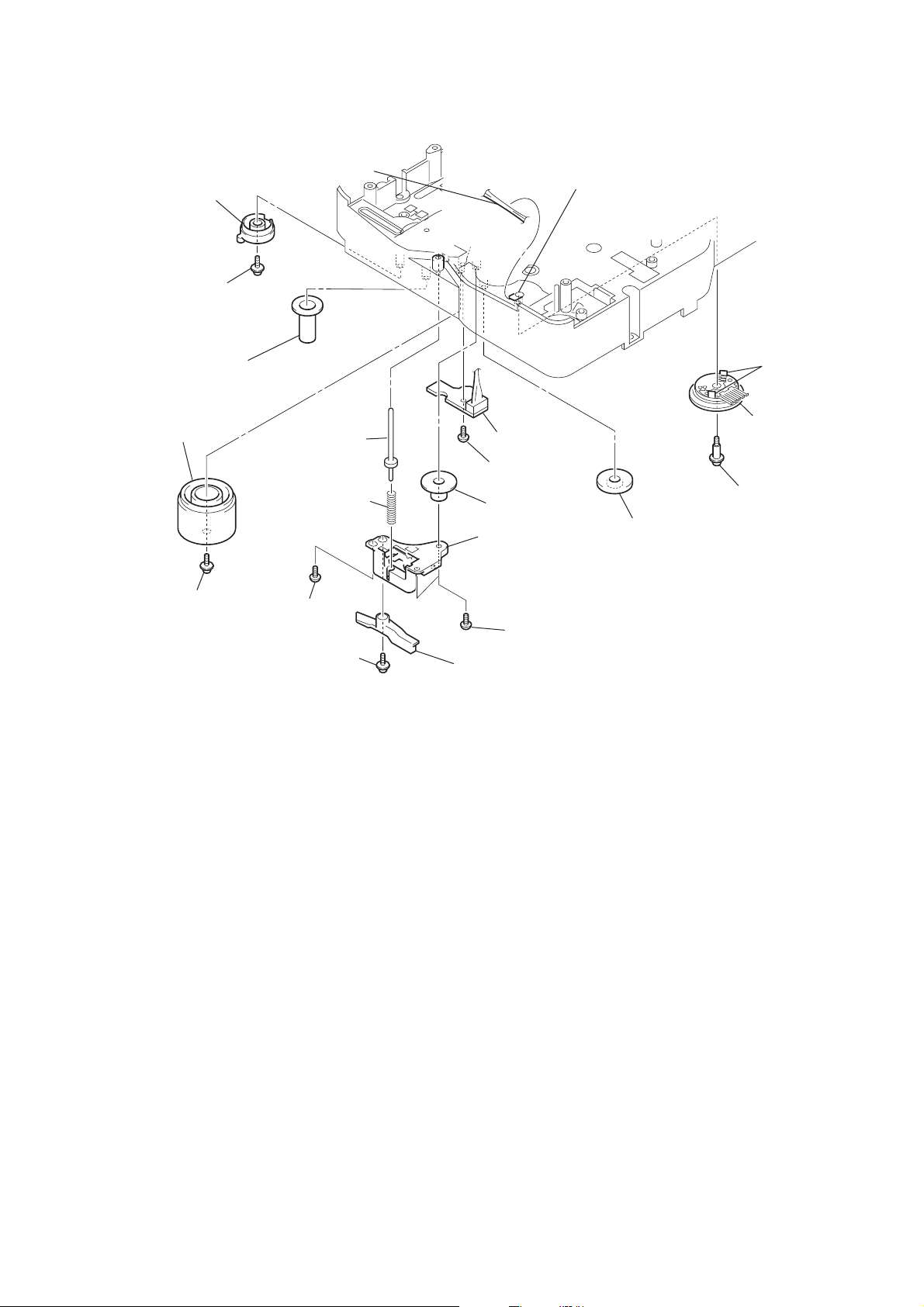
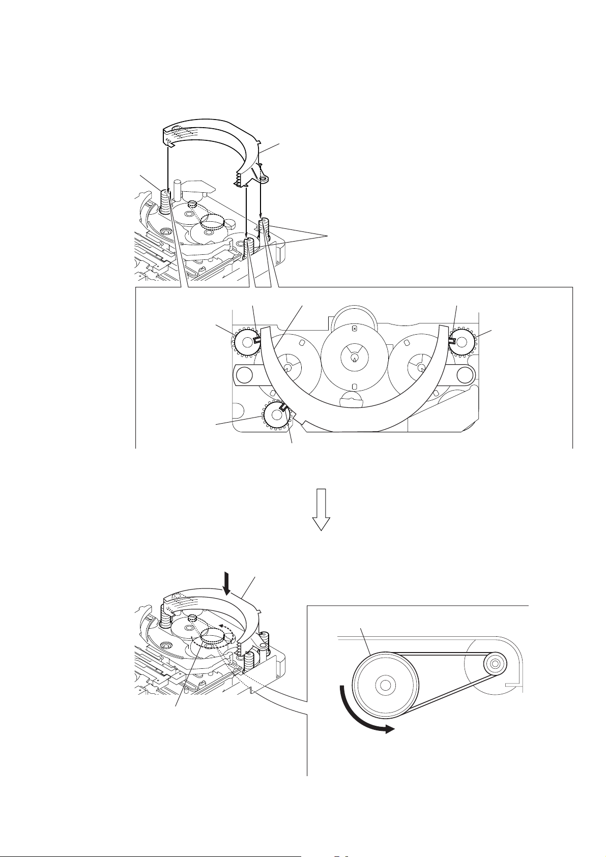
3-24. SENSOR BOARD
ql
harness
qd
gear (eject lock)
q;
cam (eject lock)
: Note
qh
two claws
qj
rotary encoder
(S771)
qf
gear
(mode B)
w;
screw
(BVTP2.6
×
8)
qg
screw
(PTPWH2.6
×
8)
wa
sensor board
8
shaft
(shutter)
7
compression spring
(shutter)
qs
cam (BU U/D)
qa
screw
(PTPWH2.6
×
8)
3
screw
(BVTP2.6
×
8)
1
screw
(PTPWH2.6
×
8)
4
two screws
(BVTP2.6
×
8)
2
lever shutter (A)
5
base (shutter) block
6
gear (mode A)
9
screw
(PTPWH2.6
×
8)
qk
claw
Note: Refer to assembly (Section 4).
CX-BK7
21
CX-BK7
SECTION 4
ASSEMBLY
• This set can be assembled in the order shown below.
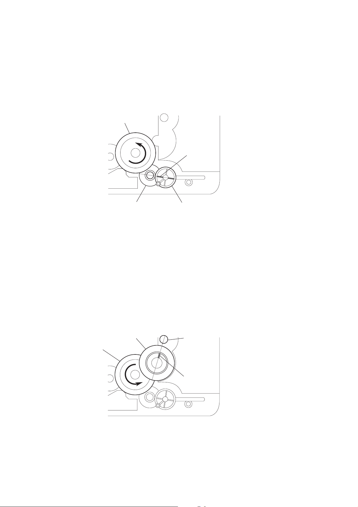
4-1. HOW TO INSTALL THE CAM (EJECT LOCK)
1
Rotate the cam (BU U/D) fully in the direction of arrow.
2
Engage the gear (eject lock) and the gear of the cam (eject lock)
aligning the mark with the center of the gear (eject lock).
cam (BU U/D)
mark
gear (eject lock)
– bottom view • front –
4-2. HOW TO INSTALL THE CAM (GEAR)
1
Check that the cam (BU U/D) can not be rotated in the direction of arrow.
2
Align the mark on the cam (gear) with the boss as shown in the figure
and install the cam (gear).
cam (gear)
cam (BU U/D)
cam (eject lock)
boss
mark
22
– bottom view • front –
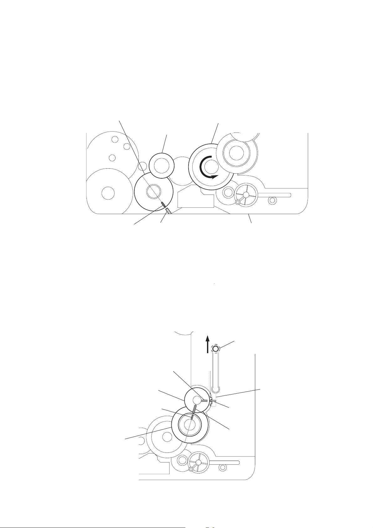
4-3. HOW TO INSTALL THE GEAR (MODE 2)
1
Align the mark on the rotary encoder (S701) with the projection of the assy.
2
Check that the cam (BU U/D) can not be rotated in the direction of arrow.
3
Install the gear (mode 2).
rotary encoder
(S701)
gear
(mode 2)
CX-BK7
cam (BU U/D)
mark projection chassis
– bottom view • front –
4-4. HOW TO INSTALL THE GEAR (MODE CAM)
1
Slide the shaft in the direction of arrow.
2
Align mark A on the gear (mode cam) with mark B on the slider (mode cam) assy,
then install the gear (mode cam).
3
Check that mark C on the gear (mode cam) is in alignment with mark D on the cam (gear).
mark
A
gear (mode cam)
shaft
slider (mode cam) assy
cam (gear)
mark
D
– bottom view • front –
mark
mark
B
C
23
CX-BK7
4-5. HOW TO INSTALL THE ROTARY ENCODER (S702), GEAR (STOCKER COMMUNICATION)
4
Engage the rotary encoder (S702)
and the gear (stocker communication)
as shown below in the figure.
rotary encoder
(S702)
gear
(stocker communication)
3
screw
(PWH2
×
6)
1
rotary encoder
(S702)
5
screw
(PTPWH2.6
×
8)
7
two screws
(PTPWH2.6
6
two gears
(stocker communication)
×
8)
gear
(stocker
communication)
– rear –
4-6. HOW TO INSTALL THE CAM (STOCKER U/D)
3
screw
(PTPWH2.6
2
cam (stocker U/D)
×
rotary encoder
(S702)
screw
8)
2
five
solders
relay board
1
Position the hole on the gear
(stocker communication) on the
screw of the rotary encoder (S702).
gear
(stocker communication)
– rear –
3
hole
two screws
(PTPWH2.6
×
8)
24
cam (stocker U/D)
f
mark
f
mark
cam (stocker U/D)
To install three cams (stocker U/D), align each groove
of the cam (stocker U/D) with each f mark on the
chassis as shown in the figure.
cam (stocker U/D)
f
mark
2
two cams
(stocker U/D)
4-7. HOW TO INSTALL THE STOCKER ASSY
1
Fit three shafts of the stocker assy in respective slits
of the cams (stocker U/D).
CX-BK7
cam (stocker U/D)
cam (stocker U/D)
cam (stocker U/D)
Note: For the location of slits of the cams (stocker U/D),
see 4-6. HOW TO INSTALL CAM (STOCKER U/D).
cam (stocker U/D)
shaft shaftstocker assy
cam (stocker U/D)
shaft
pulley (stocker)
stocker assy
pulley (stocker)
A
2
Making sure that three shafts of the stocker assy fit in
respective slits of the cams (stocker U/D), rotate the
pulley (stocker) in the direction of arrow A by hand to
store the stocker assy.
25
CX-BK7
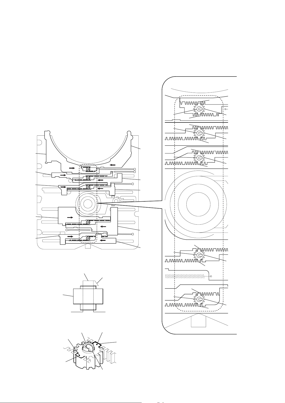
4-8. PHASE ADJUSTMENT BETWEEN PINIONS (SLIDER) AND SLIDER-1 TO 5 (L/R)
As shown in the following figure, adjust the portion A of each slider to the boss with the
1
slider-1 to 5 (L) and the slider-1 to 5 (R) pushed in the arrow directions respectively (see Fig. 1).
2
Paying attention to the up/down direction of the pinion (slider) (see Fig. 2), install each pinion (slider)
so that the portion
Note: Push in the pinion (slider) until the claw of the boss comes out above the pinion (slider) to lock.
B
of each pinion (slider) meshes with the portion A of each slider (see Fig. 3).
A
slider-5 (L)
slider-4 (L)
slider-3 (L)
slider-2 (L)
slider-1 (L)
(Fig. 1)
boss
claw
slider-5 (R)
slider-4 (R)
slider-3 (R)
slider-2 (R)
slider-1 (R)
boss
boss
boss
boss
A
A
A
A
A
A
pinion (slider)
pinion (slider)
A
pinion (slider)
pinion (slider)
26
pinion (slider)
pinion (slider) portion
slider portion
A
B
(Fig. 2)
boss
(Fig. 3)
pinion (slider) portion
slider portion
claw
A
boss
pinion (slider)
A
B
A

SECTION 5
TEST MODE
CX-BK7
[COLD RESET]
• The cold reset clears all data including preset data stored in the
RAM to initial conditions. Execute this mode when returning
the set to the customer.
Procedure:
1. Press the three buttons x , [ENTER], and [FUNCTION]
simultaneously.
2. The fluorescent indicator tube becomes blank for a while, and
the set is reset, then becomes demonstration mode.
[VERSION DISPLAY]
• This mode is used to check the model and software version.
Procedure:
1. Press the I/1 button to turn the power ON.
2. Press two buttons of x and I/1 simultaneously for five
seconds. The model name is displayed, then the software
version is displayed.
[LCD TEST]
• This mode is used to check the liquid crystal display.
Procedure:
1. Press three buttons of x , [MODE], and [FUNCTION]
simultaneously.
2. All segments of liquid crystal display are turned ON.
3. To release from this mode, press the I/1 button.
[TUNER TEST]
• This mode is used to check the change of frequency.
Procedure:
1. Press three buttons of x , [MODE], and [TUNER/BAND]
simultaneously.
2. The message “TUN TEST” is displayed on the liquid crystal
display.
3. Each time
FM frequency.
4. Press the [TUNER/BAND] button to set AM.
5. Each time Y button is pressed, the display changes preset
AM frequency.
Y button is pressed, the display changes preset
[AMP TEST]
• This mode is used to check the function of the amplifier.
Procedure:
1. Press three buttons of x , [MODE], and [i-Bass]
simultaneously.
2. The message “AMP TEST” is displayed on the liquid crystal
display.
3. When the [VOLUME] knob is turned clockwise, the message
“VOLUME MAX” is displayed on the liquid crystal display.
When the [VOLUME] knob is tur ned counterclockwise. The
message “VOLUME 0” is displayed on the liquid crystal
display.
4. Each time the [BASE] or [TREBLE/MIDDLE] knob is turned,
the message “EQ MAX”, “EQ MIN” or “EQ FLAT” is
displayed in this order on the liquid crystal display.
[USB TEST]
• This mode is used to display the status of comunication.
Procedure:
1. Press the I/1 button to turn the power ON.
2. Press the [FUNCTION] button to select “USB”.
3. Press three buttons of x , [PLAY MODE], and [i-Bass]
simultaneously.
4. The message “WINAMP3” is displayed on the liquid crystal
display at first.
[ROBBERY PREVENTION LOCK]
• This mode is used to unable to take sample disc out of set in the
shop.
Procedure:
1. Press the I/1 button to turn the power ON.
2. Press the [FUNCTION] button to select “DVD”.
3. Press two buttons of [ENTER] and Z simultaneously for five
seconds.
4. The message “LOCKED” is displayed on the liquid crystal
display and the disc is locked. (Even if pressing the Z button,
the message “LOCKED” is displayed on the liquid crystal
display and the disc is locked)
5. To release from this mode, press two buttons of [ENTER]
and Z simultaneously for five seconds again.
6. The message “UNLOCKED” is displayed on the liquid crystal
display and the disc is unlocked.
[SHIP MODE]
• This mode moves the optical pick-up to the position durable to
vibration. Use this mode when returning the set to the customer
after repair.
Procedure:
1. Press the I/1 button to turn the power ON.
2. Press the [FUNCTION] button to select “DVD”.
3. Press the x button for five seconds.
4. The message “MECHA LOCK” is displayed on the liquid crystal
display and the ship mode is set, then becomes power off.
[DECK TEST]
• This mode is used to check the tape deck operation.
Procedure:
1. Press the I/1 button to turn the power ON.
2. Press three buttons of
simultaneously.
3. The message “TC TEST” is displayed on the liquid crystal
display.
4. Press the z button to start recording.
5. When the x button is pressed during recording, the tape is
rewound back to the beginning of recording, then playback starts.
z , [MODE], and [FUNCTION]
[REPEAT 5 TIMES CANCEL]
• The number of repeat for DVD playback is 5 times when the
repeat mode is “REPEAT”. This mode enables DVD to repeat
playback for limitless times.
Procedure:
1. Press the I/1 button to turn the power ON.
2. Press the [FUNCTION] button to select “DVD”.
3. Press three buttons of x , [PLAY MODE], and [FUNCTION]
simultaneously.
4. Repeat 5 times limit is canceled.
[AM STEP CHANGE-OVER]
(Except Saudi Arabia model)
•A step of AM channels can be changed ov er between 9 kHz and
10 kHz.
Procedure:
1. Press the I/1 button to turn the power ON.
2. Press the [FUNCTION] button to select “TUNER”.
3. Press two buttons of [TUNER/BAND] and I/1 simultaneously.
27
CX-BK7
[ZIVA DEBUG MODE]
• This mode is used to unable to reset for performing the debug of
ziva.
Procedure:
1. Press the I/1 button to turn the power ON.
2. Press the [FUNCTION] button to select “DVD”.
3. Press three buttons of Y , [PLAY MODE], and [FUNCTION]
simultaneously.
4. Ziva debug mode is set.
[COLOR SYSTEM CHANGE-OVER]
(Saudi Arabia, Singapore, Malaysia and Australian
model)
• This mode is used to changed over color system.
Procedure:
1. Press the I/1 button to turn the power ON.
2. Press the [FUNCTION] button to select “DVD”.
3. Press the I/1 button to turn the power OFF.
4. Press two buttons of X and I/1 simultaneously.
5. The message “COLOR NTSC” or “COLOR P AL” is displayed
on the liquid crystal display, and the color system is changed
over NTSC or PAL.
[DVD POWER MANAGER CHANGE-OVER]
• This mode is used to changed over DVD power ON/OFF for
decreasing of reception noise in the tuner mode.
Procedure:
1. Press the I/1 button to turn the power ON.
2. Press the [FUNCTION] button to select “DVD”.
3. Press the I/1 button to turn the power OFF.
4. Press two buttons of x and I/1 simultaneously.
5. The message “DVD POWER ON” or “DVD POWER OFF”
will be displayed on the liquid crystal display, and DVD power
ON/OFF changed over in the tuner mode.
[COMPULSION INTERLACE]
• This mode is used to changed over video output into interlace.
Procedure:
1. Press the I/1 button to turn the power ON.
2. Press the [FUNCTION] button to select “DVD”.
3. Press two buttons of X and [FUNCTION] simultaneously.
4. Video output is changed over interlace.
[DVD TEST MODE GENERAL DESCRIPTION]
The T est Mode allows you to make dia gnosis and adjustment easily
using the remote commander and monitor TV. The instructions,
diagnostic results, etc. are given on the on-screen display (OSD).
[TEST DISC LIST]
Use the following test disc on test mode.
TDV-520CSO (DVD-SL): PART No. J-2501-236-A
LUV-P01 (CD): PART No. 4-999-032-01
TDV-540C (DVD-DL): PART No. J-2501-235-A
Note: Do not use existing test disc for DVD.
[STARTING DVD TEST MODE]
1. Press the I/1 button to turn the power ON.
2. Press the [FUNCTION] button to select “DVD”.
3. Press the I/1 button to turn the power OFF.
4. Press two buttons of x and [PLAY MODE] simultaneously,
and [VOLUME] knob is turned clockwise.
5. The message “SERVICE IN” is displayed on the liquid crystal display, and the Test Mode Menu is displayed on the monitor screen as follows. (At the bottom of the menu screen, the
model name and revision number are displayed)
Test Mode Menu
0. Syscon Diagnosis
1. Drive Auto Adjustment
2. Drive Manual Operation
3. Mecha Aging
4. Emergency History
5. Mecha Error History
6. Version Information
7. Video Level Adjustment
Exit: POWER Key
Model :BMZ-K7D
Revision :x.xx
6. T o execute each function, select the desired menu and press its
number on the remote commander (RM-Z20016).
7. To release from test mode, press the I/1 button and turn the
power off.
[OPERATING DVD TEST MODE]
0. SYSCON DIAGNOSIS
The same contents as board detail check by serial interface can be
checked from the remote commander operation.
On the Test Mode Menu screen, press [10/0] key on the remote
commander, and the following Check Menu will be displayed.
### Syscon Diagnosis ###
Check Menu
0. Quit
1. All
2. Version
3. EEPROM
4. GPIO
5. SD Bus
6. Video
0-0. Quit
Quit the Syscon Diagnosis and return to the Test Mode Menu.
28

CX-BK7
0-1. All (All items continuous check)
This menu checks all diagnostic items continuously. Normally, all
items are checked successively one after another automatically
unless an error is found, but at a certain item that requires judgment
through a visual check to the result, the following screen is displayed
for the key entry.
• Example display
### Syscon Diagnosis ###
Diag All Check
No.2 Version
2-2. Version
ROM Reversion = X.XX
Press NEXT Key to Continue
Press PREV Key to Repeat
For the ROM check, the check sum calculated by the syscon is
output, and therefore you must compare it with the specified value
for confirmation.
Following the message, press the > button to go to the next item,
or press the . button to repeat the same operation again.
To quit the diagnosis and return to Check Menu screen, press the
[RETURN] key on the remote commander to display Check Menu.
• Error occurred
If an error occurred, the diagnosis is suspended and error is displayed.
Press the
diagnosis, or press the . button to repeat the same check where
an error occurred, or press the > button to continue the check
from the item next to faulty item.
[RETURN] key on the remote commander to quit the
0-2. Version
0-2-2. Version
The revision number of ROM IC204 that the program for
the DVD system processor (IC207) is stored.
(4 digits hexadecimal number)
0-2-3. ROM Check Sum
The revision number of ROM IC204 that the program for
the DVD system processor (IC207) is stored.
0-2-4. Model Type
Model name is displayed. (BMZ-K7D)
0-2-5. Region
Model destination code is displayed. (2 digits number)
0-3. EEPROM Check
0-3-1. Sampling Check
EEPROM check at every 64 words.
It compares read data with write data of each address. When
there are discrepancies between two data, it displays error.
0-3-2. Detail Check
EEPROM check at every 1 word.
It compares read data with write data of each address. When
there are discrepancies between two data, it displays error.
0-4. GP I/O Check
Pull up/down setting check of the DVD system processor (IC207)
pin 150, 151 and 154 (for clock setting port).
0-5. SD Bus Check
SD bus data check between DVD decoder (IC701) and MPEG
decoder (IC207).
0-6. Video Check
Output the color bars for video level adjustment.
General Description of Checking Method
Selecting 2 and subsequent items calls the submenu screen of each
item. And selecting 2 and subsequent items executes respective
menus and outputs the results.
For the contents of each submenu, see “Check Items List” as below.
Check Items List:
0-2. Version
0-2-1. All
0-2-2. Version
0-2-3. ROM Check Sum
0-2-4. Model Type
0-2-5. Region
0-3. EEPROM Check
0-3-1. Sampling Check
0-3-2. Detail Check
0-4. GP I/O Check
0-5. SD Bus Check
0-6. Video Check
29

CX-BK7
1. DRIVE AUTO ADJUSTMENT
On the Test Mode Menu screen, press the [1] key on the remote
commander, and the Adjustment Menu will be displayed.
## Drive Auto Adjustment ##
Adjustment Menu
0. ALL
1. DVD-SL
2. CD
3. DVD-DL
Exit: RETURN
Normally, [10/0] is selected to adjust DVD (single layer), CD and
DVD (dual layer) in this order . But, individual items can be adjusted
for the case where adjustment is suspended due to an error. In this
mode, the adjustment can be made easily through the operation
following the message displayed on the screen.
The disc used for adjustment must be the one specified for
adjustment.
1-0. ALL
Press the [10/0] key on the remote commander, and the servo set
data in EEPROM will be initialized. Then, 1. DVD-SL disc, 2. CD
disc and 3. DVD-DL disc are adjusted in this order.
Each time one disc was adjusted, it is ejected. Replace it with the
specified disc following the message. You can f inish the adjustment
by pressing the
[RETURN] button on the remote commander.
1-1. DVD-SL (single layer)
Press the [1] ke y on the remote commander and insert a DVD single
layer disc following the message. Then the adjustment will be made
through the steps, then adjusted values will be written to the
EEPROM.
DVD Single Layer Disc Adjustment Steps:
1. Sled reset
2. Disc check memory SL
3. Wait 300 msec
4. Set disc type SL
5. LD on
6. Spindle start
7. Wait 1 sec
8. Focus servo on 0
9. Auto track offset adjust
10. CLVA on
11. Wait 500 msec
12. Tracking on
13. Wait 1 sec
14. Sled on
15. Check CLV on
16. Auto focus offset adjust
17. Auto focus gain adjust
18. Auto focus offset adjust
19. EQ boost adjust
20. Auto track gain adjust
21.All servo stop
22.EEP copy loop filter offset
1-2. CD
Press the [2] key on the remote commander and insert a CD disc
following the message. Then the adjustment will be made through
the steps, then adjusted values will be written to the EEPROM.
Note: During adjustment of each disc, the measurement for disc type judg-
ment is made. As automatic adjustment does not judge the disc
type unlike conventional models, take care not to insert wrong type
discs. Also, do not give a shock during adjustment.
CD Adjustment Steps
1. Sled rest
2. Disc check memory CD
3. Wait 500 msec
4. Set disc type CD
5. LD on
6. Spindle start
7. Wait 500 msec
8. Focus servo on 0
9. Auto track offset adjust
10. CLVA on
11. Wait 500 msec
12. Tracking on
13. (TC display start)
14. Wait 1 sec
15. Sled ON
16. Check CLV on
17. Auto focus offset adjust
18. Auto focus gain adjust
19. Auto focus offset adjust
20. EQ boost adjust
21. Auto track gain adjust
22. All servo stop
30
Loading...