

Page 1
WN-5000R
802.11n Wireless Router
User’s Manual
AirLive WN-5000R User’s Manual
0
Page 2

Declaration of Conformity
802.11n Wireless Router
is in conformity with
Clause Description
Electromagnetic compatibility and Radio spectrum Matters (ERM);
Essential requirements under article 3.2 of the R&TTE Directive
Electromagnetic compatibility and Radio spectrum Matters (ERM);
Electromagnetic compatibility(EMC) standard for radio equipment and
HIPERLAN equipment
Generic standard to demonstrate the compliance of low power
Electronic and electrical apparatus with the basic restrictions related
to human exposure to electromagnetic field (10MHz – 300GHz)
-General public
Safety for information technology equipment including electrical
business equipment
Manufacturer/Importer
Position/ Title : Vice President
OvisLink Corp.
5F., NO.6, Lane 130, Min-Chuan Rd.,
Hsin-Tien City, Taipei County, Taiwan
■ EN 300 328 V1.7.1
(2006-05)
Wideband transmission equipment operating in the 2.4GHz ISM band
And using spread spectrum modulation techniques; Part 1:technical
Characteristics and test conditions Part2:Harmonized EN covering
■ EN 301 489-1 V1.5.1
(2004-11)
■ EN 301 489-17 V1.2.1
Services; Part 17:Specific conditions for wideband data and
(2002-08)
■ EN 50371:2002
■ EN 60950-1:2001
■ CE marking
Signature:
Name :
Albert Yeh
Date: 2007/5/9
We, Manufacturer/Importer
Declare that the product
WN-5000R
In accordance with 89/336 EEC-EMC Directive and 1999/5 EC-R & TTE Directive
(Stamp)
Page 3

WN-5000R CE Declaration Statement
Country Declaration Country Declaration
cs
Česky [Czech]
da
Dansk [Danish]
de
Deutsch
[German]
et
Eesti [Estonian]
en
English
es
Español
[Spanish]
el
Ελληνική [Greek]
fr
Français [French]
it
Italiano [Italian]
lv
Latviski [Latvian]
sv
Svenska
[Swedish]
OvisLink Corp. tímto prohlašuje, že tento WN5000R je ve shodě se základními požadavky a
dalšími příslušnými ustanoveními směrnice
1999/5/ES.
Undertegnede OvisLink Corp. erklærer herved,
at følgende udstyr WN-5000Roverholder de
væsentlige krav og øvrige relevante krav i
direktiv 1999/5/EF.
Hiermit erklärt OvisLink Corp., dass sich das
Gerät WN-5000Rin Übereinstimmung mit den
grundlegenden Anforderungen und den übrigen
einschlägigen Bestimmungen der Richtlinie
1999/5/EG befindet.
Käesolevaga kinnitab OvisLink Corp. seadme
WN-5000R vastavust direktiivi 1999/5/EÜ
põhinõuetele ja nimetatud direktiivist tulenevatele
teistele asjakohastele sätetele.
Hereby, OvisLink Corp., declares that this WN5000R is in compliance with the essential
requirements and other relevant provisions of
Directive 1999/5/EC.
Por medio de la presente OvisLink Corp. declara
que el WN-5000Rcumple con los requisitos
esenciales y cualesquiera otras disposiciones
aplicables o exigibles de la Directiva 1999/5/CE.
ΜΕ ΤΗΝ ΠΑΡΟΥΣΑ OvisLink Corp. ΔΗΛΩΝΕΙ
ΟΤΙ WN-5000R ΣΥΜΜΟΡΦΩΝΕΤΑΙ ΠΡΟΣ ΤΙΣ
ΟΥΣΙΩΔΕΙΣ ΑΠΑΙΤΗΣΕΙΣ ΚΑΙ ΤΙΣ ΛΟΙΠΕΣ
ΣΧΕΤΙΚΕΣ ΔΙΑΤΑΞΕΙΣ ΤΗΣ ΟΔΗΓΙΑΣ
1999/5/ΕΚ.
Par la présente OvisLink Corp. déclare que
l'appareil WN-5000R est conforme aux
exigences essentielles et aux autres dispositions
pertinentes de la directive 1999/5/CE
Con la presente OvisLink Corp. dichiara che
questo WN-5000R è conforme ai requisiti
essenziali ed alle altre disposizioni pertinenti
stabilite dalla direttiva 1999/5/CE.
Ar šo OvisLink Corp. deklarē, ka WN-5000R
atbilst Direktīvas 1999/5/EK būtiskajām prasībām
un citiem ar to saistītajiem noteikumiem.
Härmed intygar OvisLink Corp. att denna WN5000R står I överensstämmelse med de
väsentliga egenskapskrav och övriga relevanta
bestämmelser som framgår av direktiv
1999/5/EG.
lt
Lietuvių
[Lithuanian]
nl
Nederlands [Dutch
mt
Malti [Maltese]
hu
Magyar
[Hungarian]
pl
Polski [Polish]
pt
Português
[Portuguese]
sl
Slovensko
[Slovenian]
sk
Slovensky [Slovak]
fi
Suomi [Finnish]
Íslenska [Icelandic]
no
Norsk [Norwegian]
Šiuo OvisLink Corp. deklaruoja, kad šis WN-5000R
atitinka esminius reikalavimus ir kitas 1999/5/EB
Direktyvos nuostatas.
Hierbij verklaart OvisLink Corp. dat het toestel WN5000R in overeenstemming is met de essentiële
eisen en de andere relevante bepalingen van richtlijn
1999/5/EG.
Hawnhekk, OvisLink Corp, jiddikjara li dan WN5000R jikkonforma mal-ħtiġijiet essenzjali u ma
provvedimenti oħrajn relevanti li hemm fid-Dirrettiva
1999/5/EC.
Alulírott, OvisLink Corp nyilatkozom, hogy a WN5000R megfelel a vonatkozó alapvetõ
követelményeknek és az 1999/5/EC irányelv egyéb
elõírásainak.
Niniejszym OvisLink Corp oświadcza, że WN-5000R
jest zgodny z zasadniczymi wymogami oraz
pozostałymi stosownymi postanowieniami Dyrektywy
1999/5/EC.
OvisLink Corp declara que este WN-5000Restá
conforme com os requisitos essenciais e outras
disposições da Directiva 1999/5/CE.
OvisLink Corp izjavlja, da je ta WN-5000R v skladu z
bistvenimi zahtevami in ostalimi relevantnimi določili
direktive 1999/5/ES.
OvisLink Corp týmto vyhlasuje, že WN-5000R spĺňa
základné požiadavky a všetky príslušné ustanovenia
Smernice 1999/5/ES.
OvisLink Corp vakuuttaa täten että WN-5000R
tyyppinen laite on direktiivin 1999/5/EY oleellisten
vaatimusten ja sitä koskevien direktiivin muiden
ehtojen mukainen
Hér með lýsir OvisLink Corp yfir því að WN-5000R er
í samræmi við grunnkröfur og aðrar kröfur, sem
gerðar eru í tilskipun 1999/5/EC.
OvisLink Corp erklærer herved at utstyret WN5000R er i samsvar med de grunnleggende krav og
øvrige relevante krav i direktiv 1999/5/EF.
A copy of the full CE report can be obtained from the following address:
OvisLink Corp.
5F, No.6 Lane 130,
Min-Chuan Rd, Hsin-Tien City,
Taipei, Taiwan, R.O.C.
This equipment may be used in AT, BE, CY, CZ, DK, EE, FI, FR, DE, GR, HU, IE, IT, LV, LT, LU, MT, NL, PL, PT, SK,
SI, ES, SE, GB, IS, LI, NO, CH, BG, RO, TR
Page 4

Federal Communication Commission Interference Statement
This equipment has been tested and found to comply with the limits for a Class B digital device, pursuant to
Part 15 of FCC Rules. These limits are designed to provide reasonable protection against harmful
interference in a residential installation. This equipment generates, uses, and can radiate radio frequency
energy and, if not installed and used in accordance with the instructions, may cause harmful interference to
radio communications. However, there is no guarantee that interference will not occur in a particular
installation. If this equipment does cause harmful interference to radio or television reception, which can be
determined by turning the equipment off and on, the user is encouraged to try to correct the interference by
one or more of the following measures:
1. Reorient or relocate the receiving antenna.
2. Increase the separation between the equipment and receiver.
3. Connect the equipment into an outlet on a circuit different from that to which the receiver is connected.
4. Consult the dealer or an experienced radio technician for help.
FCC Caution
This device and its antenna must not be co-located or operating in conjunction with any other antenna or
transmitter.
This device complies with Part 15 of the FCC Rules. Operation is subject to the following two conditions:
(1) this device may not cause harmful interference, and (2) this device must accept any interference received,
including interference that may cause undesired operation. Any changes or modifications not expressly
approved by the party responsible for compliance could void the authority to operate equipment.
IMPORTANT NOTE: FCC Radiation Exposure Statement:
This equipment complies with FCC radiation exposure limits set forth for an uncontrolled environment. This
equipment should be installed and operated with minimum distance 20cm between the radiator & your body.
This transmitter must not be co-located or operating in conjunction with any other antenna or transmitter.
COPYRIGHT
Copyright © 2007 by OvisLink Corp. All rights reserved. No part of this publication may be reproduced,
transmitted, transcribed, stored in a retrieval system, or translated into any language or computer language, in
any form or by any means, electronic, mechanical, magnetic, optical, chemical, manual or otherwise, without
the prior written permission of OvisLink Corp.
OvisLink Corp. makes no representations or warranties, either expressed or implied, with respect to the
contents hereof and specifically disclaims any warranties, merchantability or fitness for any particular purpose.
Any software described in this manual is sold or licensed "as is". Should the programs prove defective
following their purchase, the buyer (and not this company, its distributor, or its dealer) assumes the entire cost
of all necessary servicing, repair, and any incidental or consequential damages resulting from any defect in
the software. Further, this company reserves the right to revise this publication and to make changes from
time to time in the contents thereof without obligation to notify any person of such revision or changes.
WN-5000R User’s Manual
1
Page 5

Table of Contents
Chapter 1: Product Information .................................................................5
1-1 Introduction and safety information ..................................................................................5
1-2 Safety Information ...............................................................................................................6
1-4 Package Contents ...............................................................................................................7
1-5 Familiar with your new wireless broadband router.........................................................8
Chapter 2: System and Network Setup ...................................................10
2-1 Build network connection .................................................................................................10
2-2 Connecting to wireless broadband router by web browser.........................................11
2-2-1 Windows 95/98/Me IP address setup:................................................................11
2-2-2Windows 2000 IP address setup:.........................................................................12
2-2-3Windows XP IP address setup: ............................................................................14
2-2-4Windows Vista IP address setup:.........................................................................16
2-2-5 Router IP address lookup .....................................................................................18
2-3 Using ‘Quick Setup’...........................................................................................................21
2-3-1 Setup procedure for ‘Cable Modem’:..................................................................23
2-3-2 Setup procedure for ‘Fixed-IP xDSL’: .................................................................24
2-3-3 Setup procedure for ‘PPPoE xDSL’: ...................................................................25
2-3-4 Setup procedure for ‘PPTP xDSL’:......................................................................26
2-3-5 Setup procedure for ‘L2TP xDSL’:.......................................................................28
2-3-6 Setup procedure for ‘L2TP’: .................................................................................28
2-3-7 Setup procedure for ‘Telstra Big Pond’:..............................................................29
2-4 Basic Setup ........................................................................................................................30
2-4-1 Time zone and time auto-synchronization .........................................................30
2-4-2 Change management password..........................................................................31
2-4-3 Remote Management............................................................................................33
2-5 Setup Internet Connection (WAN Setup).......................................................................35
2-5-1 Setup procedure for ‘Dynamic IP’: ......................................................................36
2-5-2 Setup procedure for ‘Static IP’: ............................................................................37
2-5-3 Setup procedure for ‘PPPoE’:..............................................................................38
2-5-4 Setup procedure for ‘PPTP’: ................................................................................39
2-5-5 Setup procedure for ‘L2TP’: .................................................................................41
2-5-6 Setup procedure for ‘Telstra Big Pond’:..............................................................42
2-5-7 Setup procedure for ‘DNS’: ..................................................................................43
2-5-8 Setup procedure for ‘DDNS’: ...............................................................................44
2-6 Wired LAN Configuration .................................................................................................45
2-6-1 LAN IP section:.......................................................................................................46
2-6-2 DHCP Server:.........................................................................................................47
WN-5000R User’s Manual
2
Page 6

2-6-3 Static DHCP Leases Table: ..................................................................................48
2-7 Wireless LAN Configuration.............................................................................................50
2-7-1 Basic Wireless Settings ........................................................................................50
2-7-1-1 Setup procedure for ‘AP’:..........................................................................52
2-7-1-2 Setup procedure for ‘AP Bridge-Point to Point: .....................................53
2-7-1-3 Setup procedure for ‘AP Bridge-Point to Multi-Point’: ..........................54
2-7-1-4 Setup procedure for ‘AP Bridge – WDS’.................................................55
2-7-2 Advanced Wireless Settings.................................................................................56
2-7-3 Wireless Security ...................................................................................................59
2-7-3-1 Disable wireless security...........................................................................59
2-7-3-2 WEP - Wired Equivalent Privacy..............................................................59
2-7-3-3 Wi-Fi Protected Access (WPA):................................................................61
2-7-3-4 WPA RADIUS:.............................................................................................62
2-7-4 Wireless Access Control.......................................................................................63
2-7-5 Wi-Fi Protected Setup (WPS) ..............................................................................65
2-7-6 Security Tips for Wireless Network .....................................................................67
Chapter 3: Advanced Functions ..............................................................68
3-1 Quality of Service (QoS)...................................................................................................68
3-1-1 Basic QoS Settings................................................................................................68
3-1-2 Add a new QoS rule...............................................................................................69
3-2 Network Address Trnaslation (NAT) ...............................................................................72
3-2-1 Basic NAT Settings (Enable or disable NAT function)......................................72
3-2-2 Port Forwarding......................................................................................................73
3-2-3 Virtual Server..........................................................................................................75
3-2-4 Port Mapping for Special Applications................................................................77
3-2-5 UPnP Setting ..........................................................................................................77
3-2-6 ALG Settings ...........................................................................................................77
3-3 Firewall................................................................................................................................79
3-3-1 Access Control .......................................................................................................80
3-3-1-1 Add PC .........................................................................................................83
3-3-2 URL Blocking..........................................................................................................84
3-3-3 DoS Attack Prevention ..........................................................................................86
3-3-3-1 DoS - Advanced Settings..........................................................................88
3-3-4 Demilitarized Zone (DMZ) ....................................................................................89
3-4 System Status ....................................................................................................................91
3-4-1 System information and firmware version..........................................................91
3-4-2 Internet Connection Status ...................................................................................91
3-4-3 Device Status..........................................................................................................92
3-4-4 System Log .............................................................................................................92
WN-5000R User’s Manual
3
Page 7

3-4-5 Security Log............................................................................................................93
3-4-5 Active DHCP client list...........................................................................................94
3-4-6 Statistics ..................................................................................................................94
3-5 Configuration Backup and Restore.................................................................................96
3-6 Firmware Upgrade.............................................................................................................97
3-7 System Reset.....................................................................................................................98
Chapter 4: Appendix .................................................................................99
4-1 Hardware Specification.....................................................................................................99
4-2 Troubleshooting ...............................................................................................................100
4-3 Glossary............................................................................................................................102
WN-5000R User’s Manual
4
Page 8

Chapter 1: Product Information
1-1 Introduction and safety information
Thank you for purchasing this wireless broadband router! This high cost-efficiency router is the best choice for
Small office / Home office users, all computers and network devices can share a single xDSL / cable modem
internet connection at high speed. Easy install procedures allows any computer users to setup a network
environment in very short time - within minutes, even inexperienced. When the number of your computers and
network-enabled devices grow, you can also expand the number of network slot by simple attach a hub or
switch, to extend the scope of your network!
With built-in IEEE 802.11b/g/N wireless network capability, all computers and wireless-enabled network
devices (including PDA, cellular phone, game console, and more!) can connect to this wireless router without
additional cabling. New N wireless capability also gives you the highest speed of wireless experience
ever! With a compatible wireless card installed in your PC, you can transfer file for up to
300Mbps(transfer data rate)! The radio coverage is also doubled, so don’t worry if your office or
house is really big!
Other features of this router including:
• High Internet Access throughput
• Allow multiple users to share a single Internet line
• Supports up to 253 users
• Share a single Cable or xDSL internet connection
• Access private LAN servers from the internet
• Four wired LAN ports (10/100M) and one WAN port (10/100M)
• Provides IEEE 802.11b/g/N wireless LAN capability
• Support DHCP (Server/Client) for easy IP-address setup
• Advanced network and security features like: Special Applications, DMZ, Virtual Servers, Access
Control, Firewall.
• Allow you to monitor the router’s status like: DHCP Client Log, System Log, Security Log and
Device/Connection Status
• Easy to use Web-based GUI for network configuration and management purposes
• Remote management function allows configuration and upgrades from a remote computer (over the
Internet)
• Auto MDI / MDI-X function for all wired Ethernet ports.
WN-5000R User’s Manual
5
Page 9

1-2 Safety Information
In order to keep the safety of users and your properties, please follow the following safety instructions:
1. This router is designed for indoor use only; DO NOT place this router outdoor.
2. DO NOT put this router at or near hot or humid places, like kitchen or bathroom. Also, do not left this router
in the car in summer.
3. DO NOT pull any connected cable with force; disconnect it from the router first.
4. If you want to place this router at high places or hang on the wall, please make sure the router is firmly
secured. Falling from high places would damage the router and its accessories, and warranty will be void.
5. Accessories of this router, like antenna and power supply, are danger to small children under 3 years old.
They may put the small parts in their nose or month and it could cause serious damage to them. KEEP
THIS ROUTER OUT THE REACH OF CHILDREN!
6. The router will become hot when being used for long time (This is normal and is not a malfunction), DO
NOT put this router on paper, cloth, or other flammable materials.
7. There’s no user-serviceable part inside the router. If you found that the router is not working properly,
please contact your dealer of purchase and ask for help. DO NOT disassemble the router, warranty will be
void.
8. If the router falls into water when it’s powered, DO NOT use your hand to pick it up. Switch the electrical
power off before you do anything, or contact an experienced technician for help.
9. If you smell something strange, or even see some smoke coming out from the router or power supply,
remove the power supply or switch the electrical power off immediately, and call dealer of purchase for
help.
1-3 System Requirements
z Internet connection, provided by xDSL or cable modem with a RJ-45 Ethernet port.
z Computer or network devices with wired or wireless network interface card.
z Web browser (Microsoft Internet Explorer 4.0 or above, Netscape Navigator 4.7 or above, Opera
web browser, or Safari web browser).
z An available AC power socket (100 – 240V, 50/60Hz)
WN-5000R User’s Manual
6
Page 10
1-4 Package Contents
Before you starting to use this router, please check if there’s anything missing in the package, and contact
your dealer of purchase to claim for missing items:
□ 802.11N Wireless Router (main body, 1 pcs)……………………..1
□ Quick installation guide (1 pcs) ………………………………… 2
□ User manual CDROM (1 pcs) ………………………………….. 3
□ A/C power adapter (1 pcs) ……………………………………... 4
WN-5000R User’s Manual
7
Page 11

1-5 Familiar with your new wireless broadband router
Front Panel
LED Name Light Status Description
PWR ON Router is switched on and correctly powered
WLAN
WAN
10/100M
WAN
LNK/ACT
10/100M
LAN
LNK/ACT
On Wireless network is switched on or WPS mode is on.
Off Wireless network is switched off
Flashing Wireless LAN activity (transferring data).
On WAN port (Internet) is running at 100Mbps
Off WAN port (Internet) is running at
10Mbps
Flashing WAN activity (transferring data)
On WAN port is connected
Off WAN port is not connected
Flashing WAN activity (transferring data)
On LAN port is running at 100Mbps LAN
Off LAN port is running at 10Mbps
On LAN port is connected
Off LAN port is not connected
Flashing LAN activity (transferring data)
WN-5000R User’s Manual
8
Page 12
Back Panel
Item Name Description
Antenna A to C Antenna A, B, and C
Power Power connector, connects to A/C power adapter
Reset / WPS Reset the router to factory default settings (clear all settings) or start
WPS function. Press this button and hold for 20 seconds to clear all
settings, and press this button for less than 20 seconds to start WPS
function.
1 - 4 Local Area Network (LAN) ports 1 to 4
WAN Wide Area Network (WAN / Internet) port
WN-5000R User’s Manual
9
Page 13
Chapter 2: System and Network Setup
2-1 Build network connection
Please follow the following instruction to build the network connection between your new WIRELESS router
and your computers, network devices:
1. Connect your xDSL / cable modem to the WAN port of router by Ethernet cable.
2. Connect all your computers, network devices (network-enabled consumer devices other than computers,
like game console, or switch / hub) to the LAN port of the router.
3. Connect the A/C power adapter to the wall socket, and then connect it to the ‘Power’ socket of the router.
4. Please check all LEDs on the front panel. ‘PWR’ LED should be steadily on, WAN and LAN LEDs should
be on if the computer / network device connected to the respective port of the router is powered on and
correctly connected. If PWD LED is not on, or any LED you expected is not on, please recheck the cabling,
or jump to ‘4-2 Troubleshooting’ for possible reasons and solution.
WN-5000R User’s Manual
10
Page 14
2-2 Connecting to wireless broadband router by web browser
After the network connection is built, the next step you should do is setup the router with proper network
parameters, so it can work properly in your network environment.
Before you can connect to the router and start configuration procedures, your computer must be able to
get an IP address automatically (use dynamic IP address). If it’s set to use static IP address, or you’re unsure,
please follow the following instructions to configure your computer to use dynamic IP address:
If the operating system of your computer is….
Windows 95/98/Me - please go to section 2-2-1
Windows 2000 - please go to section 2-2-2
Windows XP - please go to section 2-2-3
Windows Vista - please go to section 2-2-4
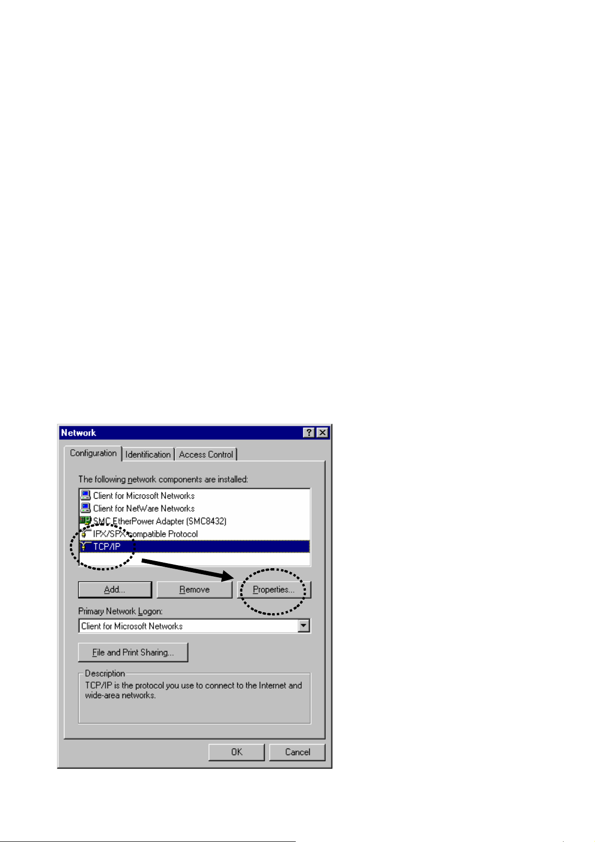
2-2-1 Windows 95/98/Me IP address setup:
1. Click ‘Start’ button (it should be located at lower-left corner of your computer), then click control panel.
Double-click Network icon, and Network window will appear. Select ‘TCP/IP’, then click ‘Properties’.
WN-5000R User’s Manual
11
Page 15
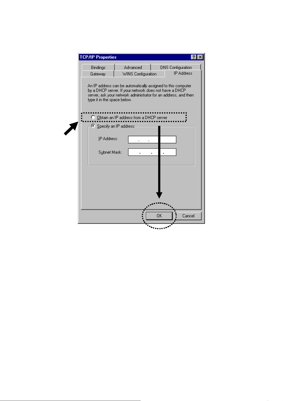
2. Select ‘Obtain an IP address from a DHCP server’, then click ‘OK’.
2-2-2 Windows 2000 IP address setup:
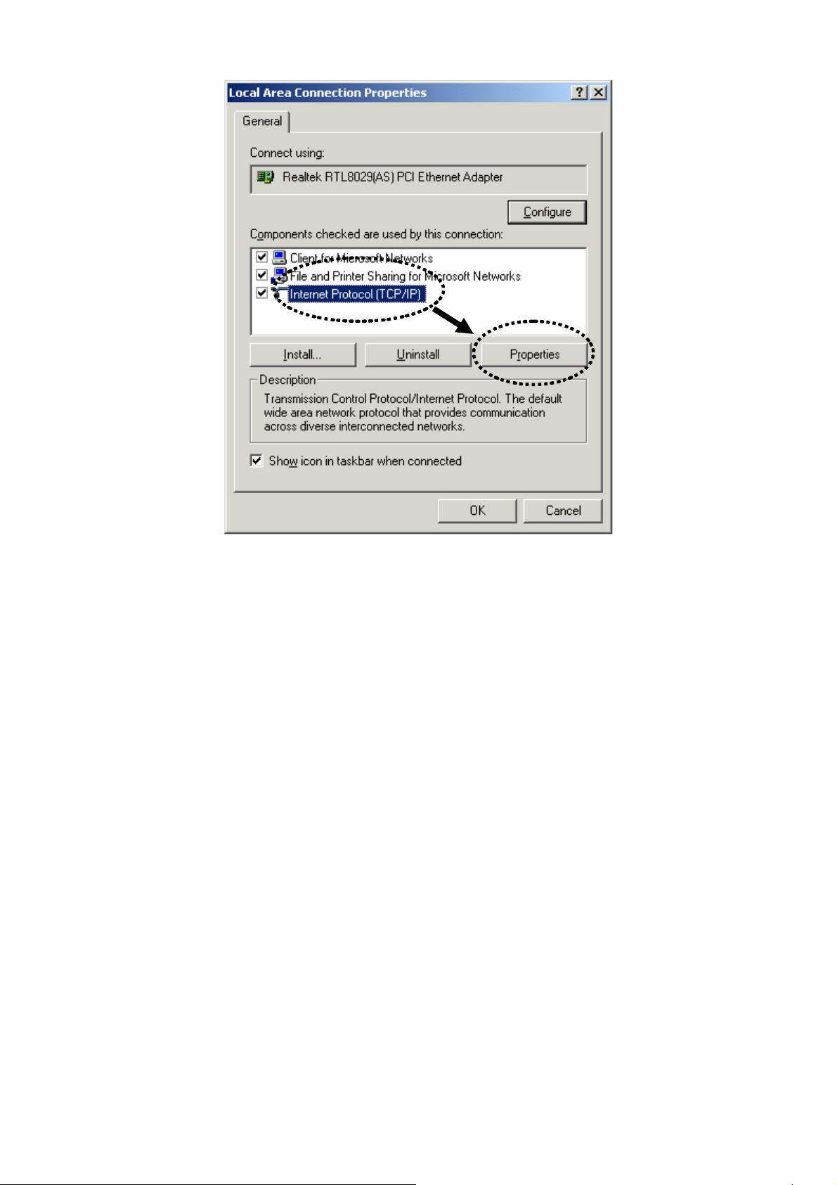
1. Click ‘Start’ button (it should be located at lower-left corner of your computer), then click control panel.
Double-click Network and Dial-up Connections icon, double click Local Area Connection, and Local Area
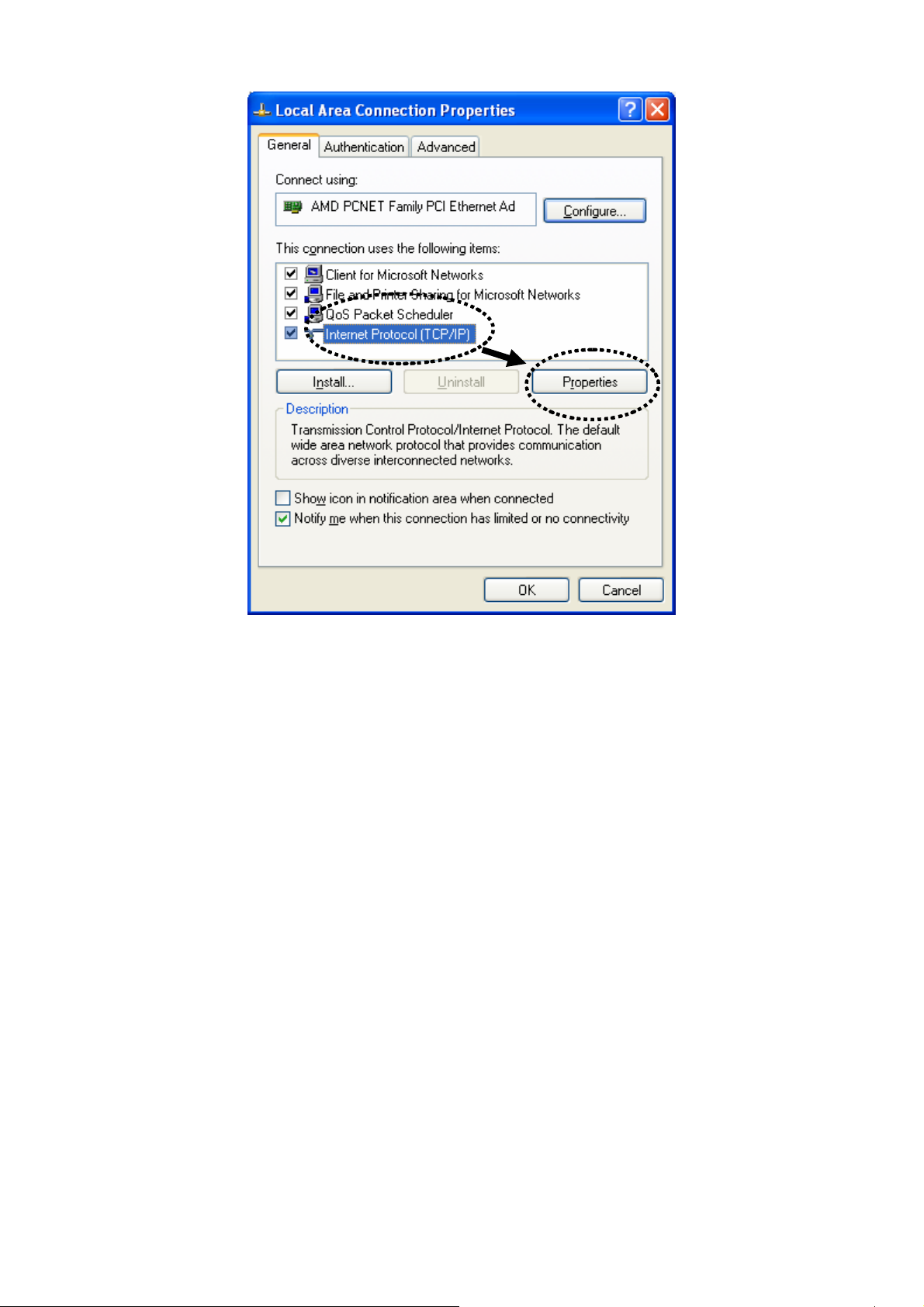
Connection Properties window will appear. Select ‘Internet Protocol (TCP/IP)’, then click ‘Properties’
WN-5000R User’s Manual
12
Page 16
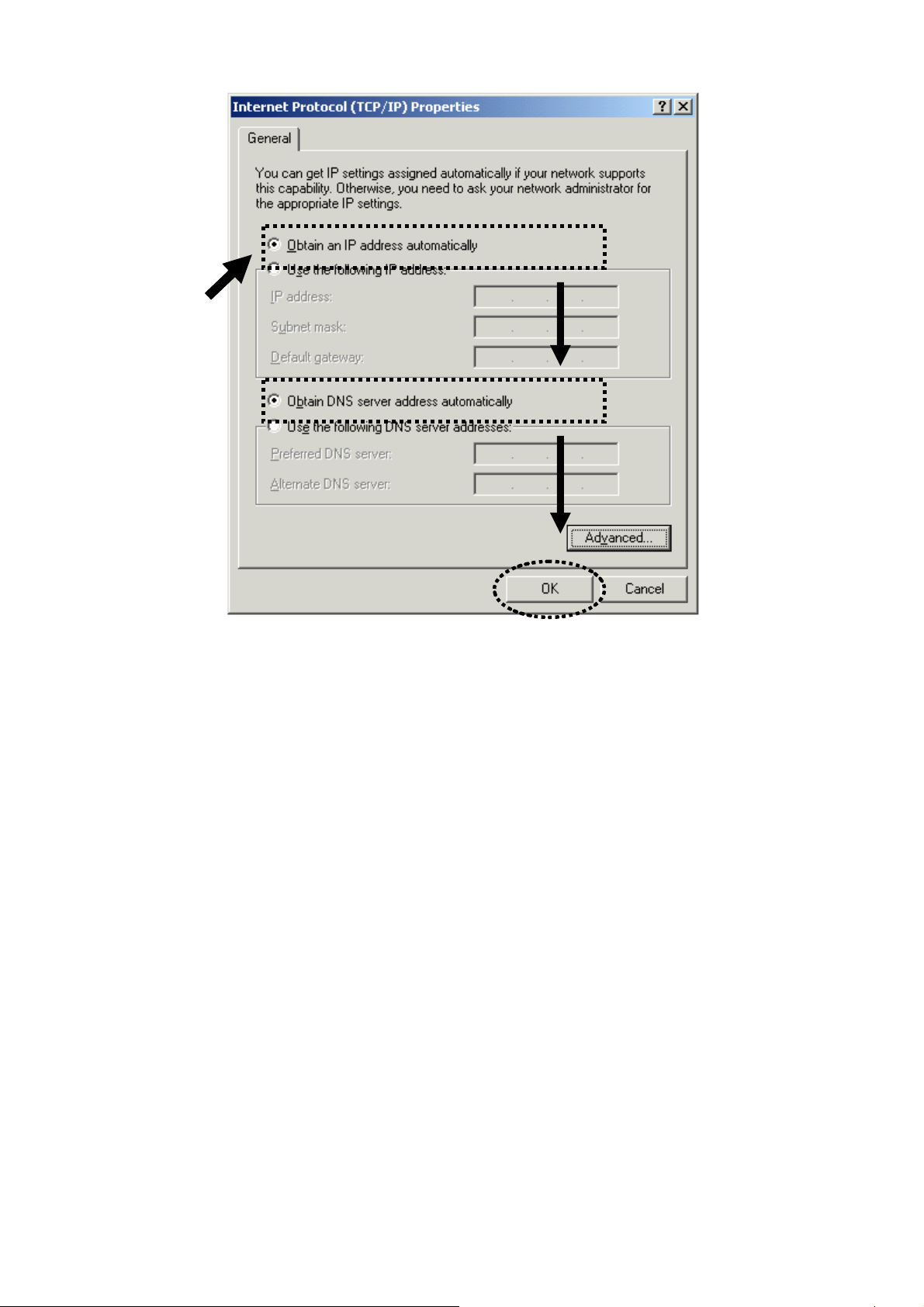
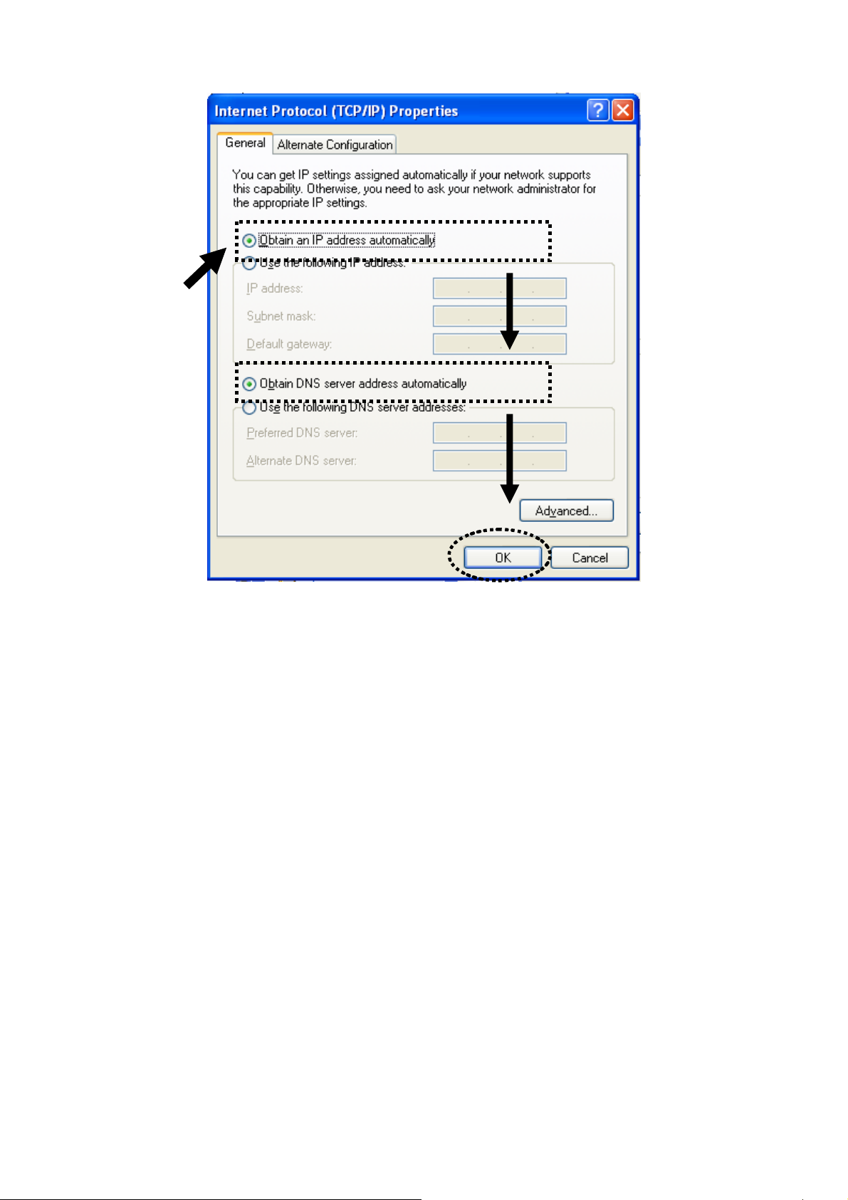
2. Select ‘Obtain an IP address automatically’ and ‘Obtain DNS server address automatically’, then click ‘OK’.
WN-5000R User’s Manual
13
Page 17
2-2-3 Windows XP IP address setup:
1. Click ‘Start’ button (it should be located at lower-left corner of your computer), then click control panel.
Double-click Network and Internet Connections icon, click Network Connections, then double-click Local
Area Connection, Local Area Connection Status window will appear, and then click ‘Properties’
WN-5000R User’s Manual
14
Page 18
2. Select ‘Obtain an IP address automatically’ and ‘Obtain DNS server address automatically’, then click ‘OK’.
WN-5000R User’s Manual
15
Page 19
2-2-4 Windows Vista IP address setup:
1. Click ‘Start’ button (it should be located at lower-left corner of your computer), then click control panel. Click
View Network Status and Tasks, then click Manage Network Connections..Right-click Local Area
Netwrok, then select ‘Properties’. Local Area Conn ection Properties window will appear, select ‘Internet
Protocol Version 4 (TCP / IPv4), and then click ‘Properties’
WN-5000R User’s Manual
16
Page 20

2. Select ‘Obtain an IP address automatically’ and ‘Obtain DNS server address automatically’, then click ‘OK’.
WN-5000R User’s Manual
17
Page 21
2-2-5 Router IP address lookup
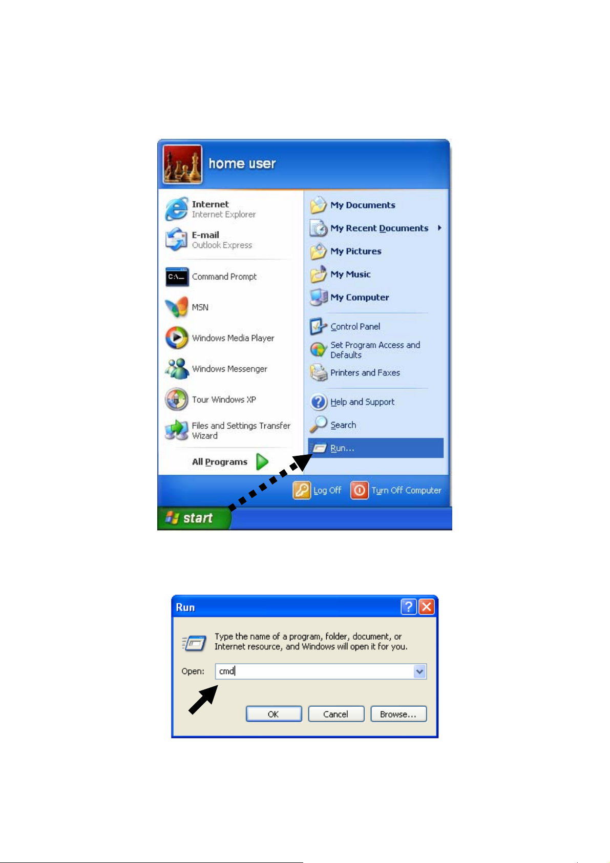
After the IP address setup is complete, please click ‘start’ -> ‘run’ at the bottom-lower corner of your desktop:
Input ‘cmd’, then click ‘OK’
Input ‘ipconfig’, then press ‘Enter’ key. Please check the IP address followed by ‘Default Gateway’ (In this
example, the IP address of router is 192.168.2.1, please note that this value may be dif f erent.)
WN-5000R User’s Manual
18
Page 22
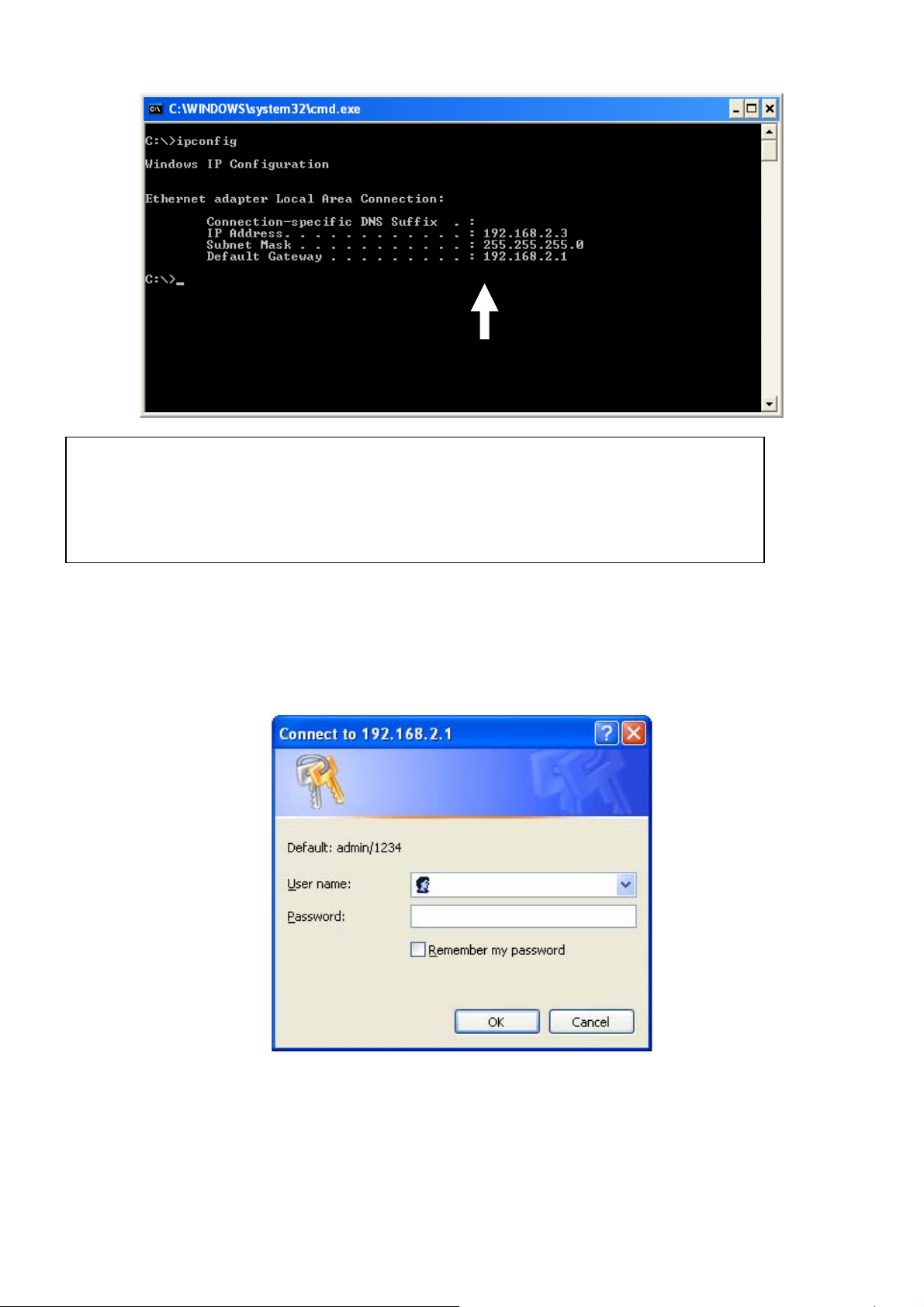
NOTE: If the IP address of Gateway is not displayed, or the address followed by ‘IP Addr ess’
begins with ‘169’, please recheck network connection between your computer and router,
and / or go to the beginning of this chapter, to recheck every step of network setup
procedure.
3. Connect the router’s management interface by web browser
After your computer obtained an IP address from router, please start your web browser, and input the IP
address of router in address bar. The following message should be shown:
Please input user name and password in the field respectively, default user name is ‘admin’, and default
password is ‘1234’, then press ‘OK’ button, and you can see the web management interface of this router:
WN-5000R User’s Manual
19
Page 23
NOTE: If you can’t see the web management interface, and you’re being prompted to
input user name and password again, it means you didn’t input username and
password correctly. Please retype user name and password again. If you’re certain
about the user name and password you type are correct, plea se go to ‘4-2
Troubleshooting’ to perform a factory reset, to set the password back to default
value.
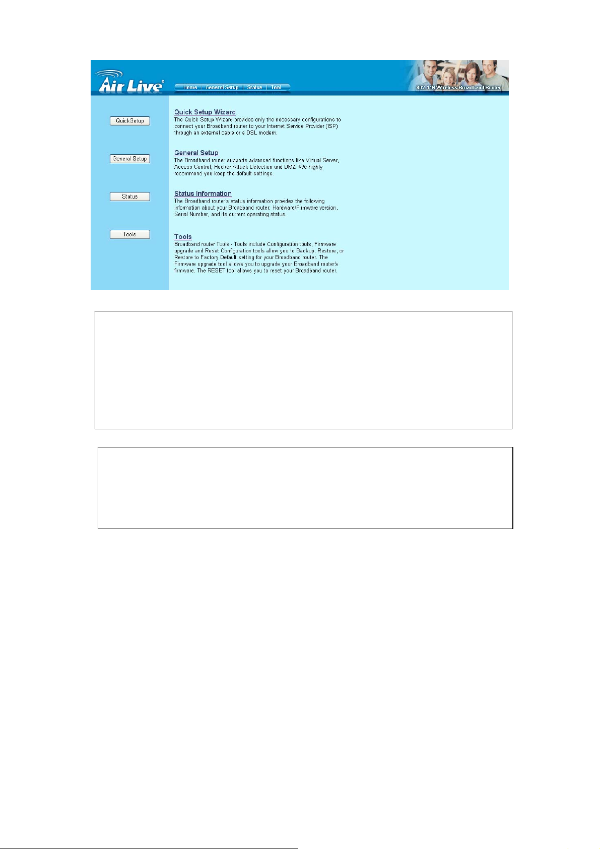
TIP: This page shows the four major setting categories: QuickSetup, Gen eral Setup,
Status, and Tools. You can find the shortcut which leads to these setting categories
at the upper-right corner of every page, and you can jump to another category
directly by clicking the link, and don’t have to go back to the first page.
WN-5000R User’s Manual
20
Page 24
2-3 Using ‘Quick Setup’
This router provides a ‘Quick Setup’ procedure, which will help you to complete all required settings you need
to access the Internet in very short time. Please follow the following instructions to complete the ‘Quick Setup’:
Please go to QuickSetup menu by clicking ‘QuickSetup’ button.
And the following message will be displayed:
1. Set Time Zone
1
2
Here are descriptions of every setup items:
Set Time Please press
Zone (1): will be shown, and you can choose a time zone of the location you live.
Time Server Input the IP address / host name of time server
button, a drop-down list
4
WN-5000R User’s Manual
21
Page 25
Address (2): here
Daylight If the country you live uses daylight saving,
Savings(3): please check ‘Enable Function’ box, and choose the duration of daylight saving.
After you finish with all settings, please click ‘Apply’ (4) button.
NOTE: There are several time servers available on internet:
129.6.15.28 (time-a.nist.gov)
132.163.4.101 (time-a.timefreq.bldrdoc.gov)
131.107.1.10 (time-nw.nist.gov)
If you found that the time of router is incorrect, try another time server.
2. Broadband Type
Please choose the broadband (Internet connection) type you’re using in this page. There are six types of
Internet connection, they are:
Cable Modem - Please go to section 2-3-1
Fixed-IP xDSL - Please go to section 2-3-2
PPPoE xDSL - Please go to section 2-3-3
PPTP xDSL - Please go to section 2-3-4
L2TP xDSL - Please go to section 2-3-5
Telstra Big Pond - Please go to section 2-3-6
WN-5000R User’s Manual
22
Page 26
If you’re not sure, please contact your Internet service provider. A wrong Internet connection type will cause
connection problem, and you will not be able to connect to internet.
If you want to go back to previous step, please press ‘Back’ button on the bottom of this page.
NOTE: Some service providers use ‘DHCP’ (Dynamic Host Configuration Protocol)
to assign IP address to you. In this case, you can choose ‘Cable Modem’ as Internet
connection type, even you’re using another connection type, like xDSL. Also, some
cable modem uses PPPoE, so you can choose ‘PPPoE xDSL’ for such cable modem
connection, even you’re using a cable modem.
2-3-1 Setup procedure for ‘Cable Modem’:
1
2
3
Here are descriptions of every setup items:
Host Name (1): Please input the host name of your computer, this is optional,
and only required if your service provider
asks you to do so.
MAC address (2): Please input MAC address of your computer here, if your service provider only
permits computer with certain MAC address to access internet. If you’re using the
computer which used to connect to Internet via cable modem, you can simply
press ‘Clone Mac address’ button to fill the MAC address field with the MAC
address of your computer.
After you finish with all settings, please click ‘OK’ (3) button; if you want to go back to previous menu, click
‘Back’.
WN-5000R User’s Manual
23
Page 27
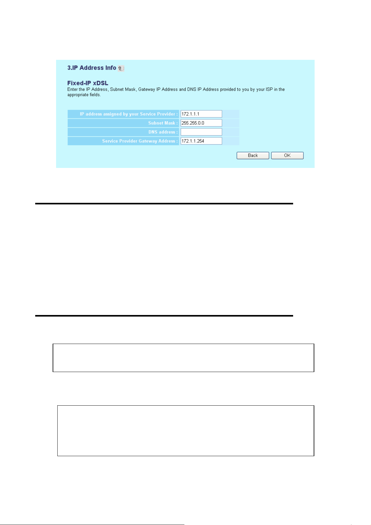
2-3-2 Setup procedure for ‘Fixed-IP xDSL’:
1
2
3
4
5
Here are descriptions of every setup items:
IP address Please input IP address assigned
assigned by your by your service provider.
Service Provider (1):
Subnet Mask (2): Please input subnet mask assigned by your service provider
DNS address (3): Please input the IP address of DNS server provided by your service provider.
Service Provider Please input the IP address of DNS server
Gateway Address (4): provided by your service provider.
You must use the addresses provided by your Internet service provider, wrong
setting value will cause connection problem.
When you finish with all settings, press ‘OK’ (5); if you want to go back to previous menu, click ‘Back’.
WN-5000R User’s Manual
NOTE: You can choose this Internet connection method if your service provider
assigns a fixed IP address (also know as static address) to you, and not using
DHCP or PPPoE protocol. Please contact your service provider for further
information.
24
Page 28
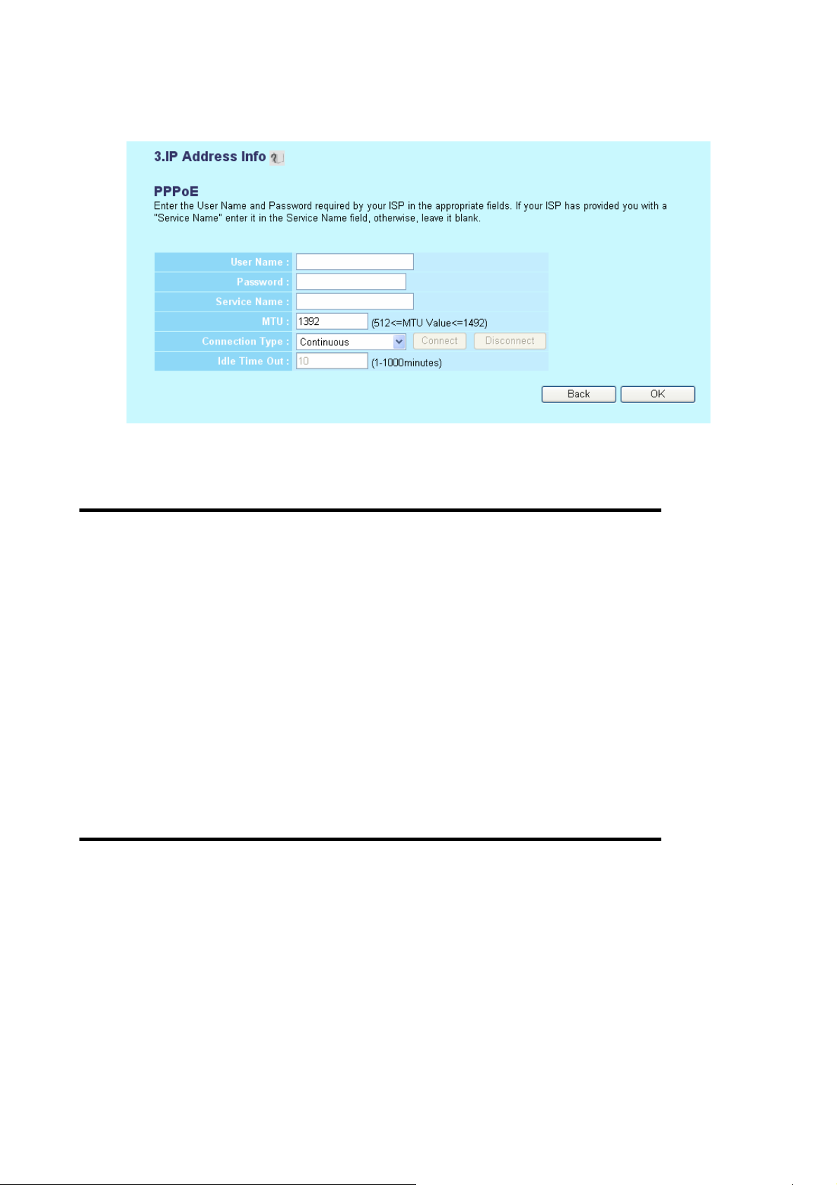
2-3-3 Setup procedure for ‘PPPoE xDSL’:
Here are descriptions of every setup items:
1
2
3
4
5
6
7
User Name (1): Please input user name assigned by your Internet service provider here.
Password (2): Please input the password assigned by your Internet service provider here.
Service Name (3): Please give a name to this Internet service, this is optional
MTU (4): Please input the MTU value of your network connection here. If you don’t know,
you can use default value.
Connection Please select the connection type of Internet
Type (5): connection you wish to use (detailed explanation listed below).
Idle Time Out (6): Please input idle tim e out, (detailed explanation listed below).
When you finish with all settings, please click ‘OK’ (7); if you want to go back to previous menu, click ‘Back’.
WN-5000R User’s Manual
25
Page 29
MTU - Please use default value if you don’t know what it is, or ask your service
provider for a proper value.
Connection Type - There are 3 options: ‘Continuous’ - keep internet connection
alive, do not disconnect, connect on Demand - only connects to Internet when
there’s a connect attempt, and ‘Manual’ - only connects to Internet when ‘Connect’
button on this page is pressed, and disconnects when ‘Disconnect button is
pressed.
Idle Time Out: Specify the time to shutdown internet connect after no in ternet
activity is detected by minute. This option is only available when connection type is
‘Connect on Demand’.
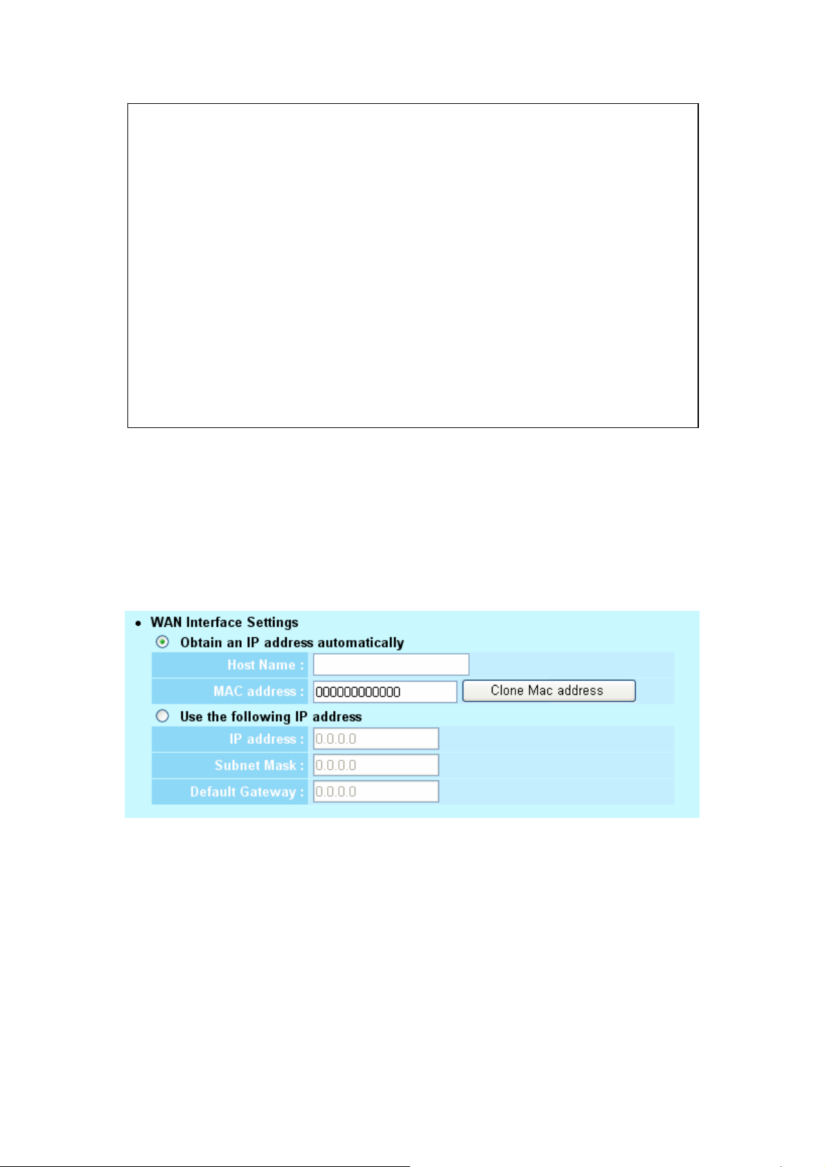
2-3-4 Setup procedure for ‘PPTP xDSL’:
PPTP xDSL requires two kinds of setting: WAN interface setting (setup IP address) and PPTP setting (PPTP
user name and password). Here we start from WAN interface setting:
Select the type of how you obtain IP address from your service provider here. You can choose ‘Obtain an IP
address automatically’ (equal to DHCP, please refer to ‘Cable Modem’ section above), or ‘Use the following IP
address’ (i.e. static IP address).
WAN interface settings must be correctly set, or the Internet connection will fail even those settings of PPTP
settings are correct. Please contact your Internet service provider if you don’t know what you should fill in
these fields.
WN-5000R User’s Manual
26
Page 30
Now please go to PPTP settings section:
1
2
3
4
5
6
7
8
Here are descriptions of every setup items:
User ID (1): Please input user ID (user name) assigned by your Internet service provider here.
Password (2): Please input the password assigned by your Internet service provider here.
PPTP Please input the IP address of PPTP gateway
Gateway (3): assigned by your Internet service provider here.
Connection Please input the connection ID here, this is
ID (4): optional and you can leave it blank.
MTU (5): Please input the MTU value of your network connection here. If you don’t know,
you can use default value.
Connection Please select the connection type of Internet
type (6): connection you wish to use, please refer to last section for detailed descriptions.
Idle Time Please input the idle time out of Internet
Out (7): connection you wish to use, and refer to last section for detailed descriptions.
Setting item ‘BEZEQ-ISRAEL’ is only required to check if you’re using the service provided by BEZEQ
network in Israel.
When you finish with all settings, please click ‘OK (8); if you want to go back to previous menu, click ‘Back’.
WN-5000R User’s Manual
27
Page 31

2-3-5 Setup procedure for ‘L2TP xDSL’:
L2TP is another popular connection method for xDSL and other Internet connection types, and all required
setting items are the same with PPTP connection.
Like PPTP, there are two kinds of required setting, we’ll start from ‘WAN Interface Settings’:
Please select the type of how you obtain IP address from your service provider here. You can choose ‘Obtain
an IP address automatically’ (equal to DHCP, please refer to ‘Cable Modem’ section above), or ‘Use the
following IP address’ (equal to static IP address, please refer to ‘PPPoE xDSL’ section above).
WAN interface settings must be correctly set, or the Internet connection will fail even those settings of PPTP
settings are correct. Please contact your Internet service provider if you don’t know what you should fill in
these fields.
2-3-6 Setup procedure for ‘L2TP’:
1
2
3
4
5
6
Here are descriptions of every setup items:
WN-5000R User’s Manual
28
7
Page 32

User ID (1): Please input user ID (user name) assigned by your Internet
service provider here.
Password (2): Please input the password assigned by your Internet service provider here.
L2TP Gateway (3): Please input the IP address of PPTP gateway assigned by your Internet service
provider here.
MTU (4): Please input the MTU value of your network connection here. If you don’t know,
you can use default value.
Connection Please select the connection type of Internet
type (5): connection you wish to use, please refer to last section for detailed descriptions.
Idle Time Please input the idle time out of Internet
Out (6): connection you wish to use, and refer to last section for detailed descriptions.
When you finish with all settings, please click ‘OK (7); if you want to go back to previous menu, click ‘Back’.
2-3-7 Setup procedure for ‘Telstra Big Pond’:
1
2
3
4
5
This setting only works when you’re using Telstra big pond’s network service in Australia. You need to input:
User Name (1): Please input the user name assigned by Telstra.
WN-5000R User’s Manual
29
Page 33

Password (2): Please input the password assigned by Telstra.
User device login Check this box to choose login
server manually (3): server by yourself.
Login Server (4): Please input the IP address of login server here.
2-4 Basic Setup
In this chapter, you’ll know how to change the time zone, password, and remote management settings. Please
start your web browser and log onto router web management interface, then click ‘General Setup’ button on
the left, or click ‘General Setup’ link at the upper-right corner of web management interface.
2-4-1 Time zone and time auto-synchronization
Please follow the following instructions to set time zone and time auto-synchronization parameters:
Please click ‘System’ menu on the left of web management interface, then click ‘Time Zone’, and the following
message will be displayed on your web browser: Please select time zone at ‘Set time zone’ drop-down list,
and input the IP address or host name of time server. If you want to enable daylight savings setting, please
check ‘Enable Function’ box, and set the duration of daylight setting. When you finish, click ‘Apply’. You’ll see
the following message displayed on web browser:
WN-5000R User’s Manual
30
Page 34

Press ‘Continue’ to save the settings made and back to web management interface; press ‘Apply’ to save the
settings made and restart the router so the settings will take effect after it reboots.
NOTE: You can refer to the instructions given in last chapter: ‘Using Quick Setup’,
for detailed descriptions on time zone settings.
2-4-2 Change management password
Default password of this router is 1234, and it’s displayed on the login prompt when accessed from web
browser. There’s a security risk if you don’t change the default password, since everyone can see it. This is
very important when you have wireless function enabled.
To change password, please follow the following instructions:
Please click ‘System’ menu on the left of web management interface, then click ‘Password Settings’, and the
following message will be displayed on your web browser:
1
2
3
Here are descriptions of every setup items:
Current Please input current password here.
Password (1):
WN-5000R User’s Manual
31
Page 35

New Password (2): Please input new password here.
Confirmed Please input new password here again.
Password (3):
When you finish, click ‘Apply’; If you want to keep original password unchanged, click ‘Cancel’.
If the password you typed in ‘New Password’ (2) and ‘Confirmed Password’ (3) field are not the same, you’ll
see the following message:
Please retype the new password again when you see above message.
It means the content in ‘Current Password’ field is wrong, please click ‘OK’ to go back to previous menu, and
try to input current password again.
If the current and new passwords are correctly entered, after you click ‘Apply’, you’ll be prompted to input your
new password:
WN-5000R User’s Manual
32
Page 36

3
Please use new password to enter web management interface again, and you should be able to login with
new password.
2-4-3 Remote Management
This router does not allow management access from Internet, to prevent possible security risks (especially
when you defined a weak password, or didn’t change default password). However, you can still management
this router from a specific IP address by enabling the ‘Remote Management’ Function.
To do so, please follow the following instructions:
Please click ‘System’ menu on the left of web management interface, then click ‘Remote Management’, and
the following message will be displayed on your web browser:
2
Here are descriptions of every setup items:
Host Address (1): Input the IP address of the remote host you wish to init iate a manag ement access.
Port (2): You can define the port number this router should expect an incoming request. If
you’re providing a web service (default port number is 80), you should try to use
other port number. You can use the default port setting ‘8080’, or something like
‘32245’ or ‘1429’. (Any integer between 1 and 65534)
NOTE: When you want to manage this router from another computer on internet,
you have to input the IP address and port number of this router. If your Internet
service provider assigns you with a static IP address, it will not be a problem; but if
the IP address your service provider assigns to you will vary every time you
establish an internet connection, this will be a problem.
Please either ask your service provider to give you a static IP address, or use
dynamic IP to host name mapping services like DDNS. Please refer to chapter 2-5-8
‘DDNS client’ for details.
WN-5000R User’s Manual
33
Page 37

NOTE: Default port number the web browser will use is ‘80’. If the ‘Port’ setting in
this page is not ‘80’, you have to assign the port number in the address bar of web
browser manually. For example, if the IP address of this router is 1.2.3.4, and the
port number you set is 8888, you have to input following address in the address bar
of web browser:
http://1.2.3.4:8888
WN-5000R User’s Manual
34
Page 38

2-5 Setup Internet Connection (WAN Setup)
Internet connections setup can be done by using ‘Quick Setup’ menu described in chapter 2-3. However, you
can setup WAN connections up by using WAN configuration menu. You can also set advanced functions like
DDNS (Dynamic DNS) here.
To start configuration, please follow the following instructions:
Please click ‘WAN’ menu on the left of web management interface, and the following message will be
displayed on your web browser:
Please select an Internet connection method depend on the type of connection you’re using. You can either
click the connection method on the left (1) or right (2). If you select the connection method on the right, please
click ‘More Configuration’ button after a method is selected.
Dynamic IP - Please go to section 2-5-1
Static IP - Please go to section 2-5-2
PPPoE - Please go to section 2-5-3
PPTP - Please go to section 2-5-4
L2TP - Please go to section 2-5-5
Telstra Big Pond - Please go to section 2-5-6
DNS - Please go to section 2-5-7
DDNS - Please go to section 2-5-8
WN-5000R User’s Manual
35
Page 39

2-5-1 Setup procedure for ‘Dynamic IP’:
1
2
3
Here are descriptions of every setup items:
Host Name (1): Please input host name of your computer, this is optional, and only required if your
service provider asks you to do so.
MAC Address (2): Please input MAC address of your computer, if your service provider only permits
computer with certain MAC address to access inte rnet. If you’re using the
computer which used to connect to Internet via cable modem, you can simply
press ‘Clone Mac address’ button to fill the MAC address field with the MAC
address of your computer,
WN-5000R User’s Manual
36
Page 40

2-5-2 Setup procedure for ‘Static IP’:
Here are descriptions of every setup items:
IP address assigned Please input IP address assigned
by your Service by your service provider.
1
2
3
4
Provider (1):
Subnet Mask (2): Please input subnet mask assign ed by your service provider
Service Provider Please input the IP address of DNS
Gateway Address (3): server provided by your service provider.
WN-5000R User’s Manual
37
Page 41

2-5-3 Setup procedure for ‘PPPoE’:
1
2
3
4
7
User Name (1): Please input user name assigned by your Internet service provider here.
Password (2): Please input the password assigned by your Internet service provider here.
Service Name (3): Please give a name to this Internet service, this is optional
MTU (4): Please input the MTU value of your network connection here. If you don’t know,
you can use default value.
Connection Please select the connection type of Internet
Type (5): connection you wish to use (detailed explanation listed below).
Idle Time Out (6): Please input idle time out, (detailed explanation listed below).
WN-5000R User’s Manual
38
Page 42

2-5-4 Setup procedure for ‘PPTP’:
PPTP requires two kinds of setting: WAN interface setting (setup IP address) and PPTP setting (PPTP user
name and password). Here we start from WAN interface setting:
Select the type of how you obtain IP address from your service provider here. You can choose ‘Obtain an IP
address automatically’ (equal to DHCP, please refer to ‘Cable Modem’ section above), or ‘Use the following IP
address’ (i.e. static IP address)
WAN interface settings must be correctly set, or the Internet connection will fail even those settings of PPTP
settings are correct. Please contact your Internet service provider if you don’t know what you should fill in
these fields.
Now please go to PPTP settings section:
1
3
4
5
6
7
8
Here are descriptions of every setup items:
User ID (1): Please input user ID (user name) assigned by your Internet service provider here.
WN-5000R User’s Manual
39
Page 43

Password (2): Please input the password assigned by your Internet service provider here.
PPTP Gateway (3): Please input the IP address of PPTP gateway assigned by your Internet service
provider here.
Connection ID (4): Please input the connection ID here, this is optional and you can leave it blank.
MTU (5): Please input the MTU value of your network connection here. If you don’t know,
you can use default value.
Connection Please select the connection type of Internet
type (6): connection you wish to use, please refer to last section for detailed descriptions.
Idle Time Out (7): Please input the idle time out of Internet connection you wish to use, and refer to
last section for detailed descriptions.
Setting item ‘BEZEQ-ISRAEL’ is only required to check if you’re using the service provided by BEZEQ
network in Israel.
When you finish with all settings, please click ‘OK (8); if you want to go back to previous menu, click ‘Back’.
WN-5000R User’s Manual
40
Page 44

2-5-5 Setup procedure for ‘L2TP’:
1
2
3
4
6
Here are descriptions of every setup items:
User ID (1): Please input user ID (user name) assigned by your Internet service provider here.
Password (2): Please input the password assigned by your Internet service provider here.
L2TP Please input the IP address of PPTP gateway
Gateway (3): assigned by your Internet service provider here.
MTU (4): Please input the MTU value of your network conne ction here. If you don’ t know, you can
use default value.
Connection Please select the connection type of Internet connection
type (5): you wish to use, please refer to last section for detailed descriptions.
Idle Time Please input the idle time out of Internet connection
Out (6): you wish to use, and refer to last section for detailed descriptions.
When you finish with all settings, please click ‘OK (7); if you want to go back to previous menu, click ‘Back’.
WN-5000R User’s Manual
41
Page 45

2-5-6 Setup procedure for ‘Telstra Big Pond’:
1
2
3
4
5
This setting only works when you’re using Telstra big pond’s network service in Australia. You need to input:
User Name (1): Please input the user name assigned by Telstra.
Password (2): Please input the password assigned by Telstra.
User device login Check this box to choose login server by yourself.
server manually (3):
Login Server (4): Please input the IP address of login server here.
When you finish with all settings, click ‘OK (5); if you want to go back to previous menu, click ‘Back’.
WN-5000R User’s Manual
42
Page 46

2-5-7 Setup procedure for ‘DNS’:
If you select ‘Dynamic IP’ or ‘PPPoE’ as Internet connection method, at least one DNS server’s IP address
should be assigned automatically. However, if you have preferred DNS server, or your service provider didn’t
assign the IP address of DNS server because of any reason, you can input the IP address of DNS server
here.
1
2
Here are descriptions of every setup items:
DNS Address (1): Please input the IP address of DNS server provided by your service provider.
Secondary Please input the IP address of another DNS
DNS Address (2): server provided by your service provider, this is optional.
NOTE: Only IP address can be entered here; DO NOT use the hostname of DNS
server! (i.e. only numeric characters and dots ar e accepted)
10.20.30.40……………………………………………………………… Correct
dns.serviceprovider.com…………………………………………... Incorrect
WN-5000R User’s Manual
43
Page 47

2-5-8 Setup procedure for ‘DDNS’:
DDNS (Dynamic DNS) is a IP-to-Hostname mapping service for those Internet users who don’t have a static
(fixed) IP address. It will be a problem when such user wants to provide services to other users on Internet,
because their IP address will vary every time when connected to Internet, and other user will not be able to
know the IP address they’re using at a certain time.
This router supports DDNS service of following service providers:
DynDNS (
TZO (
Please go to one of DDNS service provider’s webpage listed above, and get a free DDNS account by the
instructions given on their webpage.
http://www.dyndns.org)
http://www.tzo.com)
1
3
4
5
6
Here are descriptions of every setup items:
Dynamic DNS (1): If you want to enable DDNS function, please select ‘Enabled’; otherwise please
select ‘Disabled’.
Provider (2): Select your DDNS service provider here.
Domain Name (3): Input the domain name you’ve obtained from DDNS service provider.
Account / Input account or email of DDNS registration.
E-Mail (4):
Password / Key (5): Input DDNS service password or key.
WN-5000R User’s Manual
44
Page 48

2-6 Wired LAN Configuration
Before all computers using wired Ethernet connection (i.e. those computers connect to this router’s LAN port
1 to 4 by Ethernet cable) can communicate with each other and access internet, they must have a valid IP
address.
There are two ways to assign IP addresses to computers: static IP address (set the IP address for every
computer manually), and dynamic IP address (IP address of computers will be assigned by router
automatically. It’s recommended for most of computers to use dynamic IP address, it will save a lot of time on
setting IP addresses for every computer, especially when there are a lot of computers in your network; for
servers and network devices which will provide services to other computer and users that come from Internet,
static IP address should be used, so other computes can locate the server.
Suggestions on IP address numbering plan:
If you have no idea on how to define an IP address plan for your network, here
are some suggestions.
1. A valid IP address has 4 fields: a.b.c.d, for most of home and company
users, it’s suggested to use 192.168.c.d, where c is an integer between 0
and 254, and d is an integer between 1 and 254. This router is capable to
work with up to 253 clients, so you can set ‘d’ field of IP address of router
as 1 or 254 (or any number between 1 and 254), and pick a number between
0 and 254 for field ‘c’.
2. In most cases, you should use ‘255.255.255.0’ as subnet mask, which
allows up to 253 clients (this also meets router’s capability of working with
up to 253 clients).
3. For all servers and network devices which will provide services to other
people (like Internet service, print service, and file service), they should
use static IP address. Give each of them a unique number between 1 and
253, and maintain a list, so everyone can locate those servers easily.
4. For computers which are not dedicated to provide specific service to
others, they should use dynamic IP address.
If you don’t really understand the descriptions listed above, don’t worry! We
will provide recommended setup values below.
WN-5000R User’s Manual
45
Page 49

Please follow the following instructions to set wired LAN parameters:
Please click ‘LAN’ menu on the left of web management interface, there are three setup groups here: ‘LAN IP’,
‘DHCP Server’, and ‘Static DHCP Leases Table’. Here are setup instructions for each of them:
2-6-1 LAN IP section:
1
2
3
4
Here are descriptions of every setup items:
IP address (1): Please input the IP address of this router.
Subnet Mask (2): Please input subnet mask for this network.
802.1d If you wish to activate 802.1d spanning tree
Spanning Tree (3): function, select ‘Enabled’ for setup item ‘802.1d Spanning Tree’, or set it to
‘Disabled’
DHCP Server (4): If you want to activate DHCP server function of this router, select ‘Enabled’, or set
it to ‘Disabled’.
Recommended Value if you don’t know what to fill:
IP Address: 192.168.1.254
Subnet Mask: 255.255.255.0
802.1d Spanning Tree: Disabled
DHCP Server: Enabled
WN-5000R User’s Manual
46
Page 50

2-6-2 DHCP Server:
1
2
3
4
These settings are only available when ‘DHCP Server’ in ‘LAN IP’ section is ‘Enabled’, and here are
descriptions of every setup items:
Lease Time (1): Please choose a lease time (the duration that every computer can keep a specific
IP address) of every IP address assigned by this router from dropdown menu.
Start IP (2): Please input the start IP address of the IP range.
End IP (3): Please input the end IP address of the IP range.
Domain Name (4): If you wish, you can also optionally input the domain name for your network. This
is optional.
Recommended Value if you don’t know what to fill:
Lease Time: Two Weeks (or ‘Forever’, if you have less than 20 computers)
Start IP: 192.168.1.1
End IP: 192.168.1.200
Domain Name: (leave it blank)
NOTE:
1. The number of the last field (mentioned ‘d’ field) of ‘End IP’ must be greater than
‘Start IP’, and can not the same with router’s IP address.
2. The former three fields of IP address of ‘Start IP’, ‘End IP’, and ‘IP Address of ‘LAN
IP’ section (mentioned ‘a’, ‘b’, and ‘c’ field) should be the same.
3. These settings will affect wireless clients, too.
WN-5000R User’s Manual
47
Page 51

2-6-3 Static DHCP Leases Table:
This function allows you to assign a static IP address to a specific computer forever, so you don’t have to
set the IP address for a computer, and still enjoy the benefit of using DHCP server. Maximum 16 static IP
addresses can be assigned here.
(If you set ‘Lease Time’ to ‘forever’ in ‘DHCP Server’ section, you can also assign an IP address to a
specific computer permanently, however, you will not be able to assign a certain IP address to a specific
computer, since IP addresses will be assigned in random order by this way).
1
2 3 4
Here are descriptions of every setup items:
Enable Static Check this box to enable this function,
DHCP Leases (1): otherwise uncheck it to disable this function.
MAC Address (2): Input the MAC address of the computer or network device (total 12 characters,
with character from 0 to 9, and from a to f, like ‘001122aabbcc’)
IP address (3): Input the IP address you want to assign to this computer or network device
‘Add’ (4): After you inputted MAC address and IP addre ss pai r, click this button to add the
pair to static DHCP leases table.
If you want to remove all characters you just entered, click ‘Clear’.
After you clicked ‘Add’, the MAC address and IP address mapping will be added to ‘Static DHCP Leases
Table’ section.
If you want to delete a specific item, please check the ‘Select’ box of a MAC address and IP address
WN-5000R User’s Manual
48
Page 52

mapping (1), then click ‘Delete Selected’ button (2); if you want to delete all mappings, click ‘Delete All’ (3).
If you want to deselect all mappings, click ‘Reset (4).
WN-5000R User’s Manual
49
Page 53

2-7 Wireless LAN Configuration
If your computer, PDA, game console, or other network devices which is equipped with wireless network
interface, you can you can use the wireless function of this router to let them connect to Internet and share
resources with other computers with wired-LAN connection. You can also use the built-in security functions
to protect your network from being intruded by malicious intruders.
Please follow the following instructions to set wireless parameters:
Please click ‘Wireless’ menu on the left of web management interface, and the following message will be
displayed on your web browser. You must enable wireless function of this router, or the wireless interface of
this router will not function. Please select ‘Enable’ (1), then click ‘Apply’ (2) button.
If you’re coming here because you want to disable wireless function, please select ‘Disable’ (3), then click
‘Apply’ (2) button.
After you click ‘Apply’, the following message will be displayed on your web browser:
Please click ‘Continue’ to back to previous setup menu; to continue on other setup procedures, or click ‘Apply’
to reboot the router so the settings will take effect (Please wait for about 50 seconds while router is rebooting).
2-7-1 Basic Wireless Settings
Please click ‘Wireless’ menu on the left of web management interface, then click ‘Basic Settings’, and the
following message will be displayed on your web browser:
WN-5000R User’s Manual
50
Page 54

1
2
3
4
5
This wireless router can be work in 4 modes:
a. AP: Standard wireless AP (access point).
b. AP Bridge-Point to Point: Connect this router with another wireless router, to expand the scope of network.
c. AP Bridge-Point to Multi-Point: Connect this router with up to four other wireless routers, to expand the
scope of network.
d. AP Bridge-WDS: Connect this router with up to four WDS-capable wireless routers, to expand the scope of
network.
NOTE: For ‘AP Bridge-Point to Point’ and ‘AP Bridge-Point to Multi-Point’ mode,
wireless router is operated in wireless bridge dedicated mode – wireless router is
only used to expand the scope of network, and no wireless clients will be accepted.
If you want to use your wireless router to expand the scope of network, and also
accept wireless clients, please select ‘AP Bridge-WDS’ mode.
Please select a proper operation mode you want to use from ‘Mode’ dropdown menu (1), and continue on
other operation mode specific settings:
AP - Please go to section 2-7-1-1
AP Bridge-Point to Point - Please go to section 2-7-1-2
AP Bridge-Point to Multi Point - Please go to section 2-7-1-3
AP Bridge-WDS - Please go to section 2-7-1-4
WN-5000R User’s Manual
51
Page 55

2-7-1-1 Setup procedure for ‘AP’:
Please select the radio band you want to use from ‘Band’ dropdown menu (2), and the following message will
be displayed:
1
2
3
4
Here are descriptions of every setup items:
Band (2): Please select the radio band from one of following options:
2.4 GHz (B) 2.4GHz band, only allows 802.11b wireless network client to
connect this router (maximum transfer rate 11Mbps).
2.4 GHz (N) 2.4GHz band, only allows 802.11n wireless network client to
connect this router (maximum transfer rate 108**Mbps).
2.4 GHz (B+G) 2.4GHz band, only allows 802.11b and 802.11g wireless
2.4 GHz (G) 2.4GHz band, only allows 802.11g wireless network client to
2.4 GHz (B+G+N) 2.4GHz band, allows 802.11b, 802.11g, and 802.11n wireless
network client to connect this router (maximum transfer rate
11Mbps for 802.11b clients, and maximum 54Mbps for 802.11g
clients).
connect this router (maximum transfer rate 11Mbps).
network client to connect this router (maximum transfer rate
11Mbps for 802.11b clients, maximum 54Mbps for 802.11g
ESSID (3): This is the name of wireless router. You can type any alphanumerical characters
here, maximum 32 characters. ESSID is used to identify your own wireless router
from others when there are other wireless routers in the same area. Default SSID
is ‘default’, it’s recommended to change default ESSID value to the one which is
meaningful to you, like myhome, office_room1, etc.
Channel Number (4): Please select a channel from the dropdo wn list of ‘Channel Number’, available channel
WN-5000R User’s Manual
52
Page 56

numbers are 1 to 13. You can choose any channel number you want to use, and
almost all wireless clients can locate the channel you’re using automatically
without any problem. However, it’s still useful to remember the channel number
you use, some wireless client supports manual channel number select, and this
would help in certain scenario when there is some radio communication problem.
NOTE: If you don’t special reason to limit the type of allowed wireless client, it’s
recommended to choose ‘2.4 GHz (B+G+N) to maximize wireless client
compatibility.
TIPS: You can try to change channel number to another one if you think the data
transfer rate is too slow, or keep having problem while transferring the file over
wireless network. There could be some other wireless routeres using the same
channel, which will disturb the radio communication between wireless client and
the wireless router.
2-7-1-2 Setup procedure for ‘AP Bridge-Point to Point:
In this mode, you can connect your wireless router with another, to combine two access points and expand
the scope of wireless network, and all clients (wired only – AP will not accept wireless clients in this mode) of
two wireless routers will think they’re on the same physical network. This function is very convenient when
you need to connect two networks between two buildings. Here are instructions about how to connect two
wireless routers together:
1
2
3
4
5
WN-5000R User’s Manual
53
Page 57

NOTE: Two wireless routers must use the same mode, band, channel number, and
security setting!
Here are descriptions of every setup items:
Band (2) Select the band you want to use, two wireless routers must use the same setting.
Channel Select the channel you want to use, two wireless
Number (3) routers must use the same setting.
MAC
address (4) Input the MAC address of another wireless router.
Set Click to set security settings for this connection
Security (5) (Plea se go to section ‘2-7-3 Wireless Security’
for detailed instructions).
NOTE: If you didn’t see popup window, please check the web browser or antivirus
program, some of them will block popup window.
2-7-1-3 Setup procedure for ‘AP Bridge-Point to Multi-Point’:
1
2
3
4
5
6
7
8
Here are descriptions of every setup items:
WN-5000R User’s Manual
54
Page 58

Band (2) Select the band you want to use, two wireless routers must use the same setting.
Channel Select the channel you want to use, two wireless
Number (3) routers must use the same setting.
MAC address Input the MAC address of other wireless routers.
1 to 4 (4 - 7)
Set Click to set security settings for this connection
Security (8) (Plea se go to section ‘2-7-3 Wireless Security’
for detailed instructions).
2-7-1-4 Setup procedure for ‘AP Bridge – WDS’
In this mode, you can expand the scope of network by combining up to four other access points together, and
every access point can still accept wireless clients.
1
2
3
4
5
6
7
8
9
Here are descriptions of every setup items:
Band (2) Select the band you want to use, two wireless routers must use the same setting.
WN-5000R User’s Manual
55
Page 59

ESSID (3) Input the ESSID of your wireless router, it can be the same with other wireless
routers for the convenience of roaming, or different with other wireless routers so
you can identify each of them.
Channel Select the channel you want to use, two wireless
Number (4) routers must use the same setting.
MAC address Input the MAC address of other wireless routers.
1 to 4 (5 - 8)
Set Click to set security settings for this connection
Security (9) (Plea se go to section ‘2-7-3 Wireless Security’
for detailed instructions).
2-7-2 Advanced Wireless Settings
This router provides some advanced control of wireless parameters, if you want to configure these settings,
please click ‘Wireless’ menu on the left of web management interface, then click ‘Advanced Settings’, and the
following message will be displayed on your web browser:
1
2
3
4
5
6
7
8
9
WN-5000R User’s Manual
56
10
11
12
13
Page 60

Here are descriptions of every setup items:
Fragment Set the Fragment threshold of wireless radio.
Threshold: Do not modify default value if you don’t know what it is, default value is
2346.
RTS Threshold: Set the RTS threshold of wireless radio. Do not modify default value if you
don’t know what it is, default value is 2347.
Beacon Interval: Set the beacon interval of wireless radio. Do not modify default value if you
don’t know what it is, default value is 100.
DTIM Period: Set the DTIM period of wireless radio. Do not modify default value if you don’t
know what it is, default value is 3.
Data Rate: Set the wireless data transfer rate to a certain value. Since most of wireless
devices will negotiate with each other and pick a proper data transfer rate
automatically, it’s not necessary to change this value unless you know what
will happen after modification.
N Data Rate: Same as above, but only for 802.11n clients.
Channel Width: Set channel width of wireless radio. Do not modify default value if you don’t
know what it is, default setting is ‘Auto 20/40 MHz’.
Preamble Type: Set the type of preamble of wireless radio, Do not modify default value if you
don’t know what it is, default setting is ‘Short Preamble’.
Broadcast ESSID: Decide if the wireless router will broadcast its own ESSID or not. Y ou can hide the
ESSID of your wireless router (set the option to ‘Disable’), so only people those
who know the ESSID of your wireless router can get connected.
CTS Protect: Enabling this setting will reduce the chance of radio signal collisions between
802.11b and 802.11g wireless access points. It’s recommended to set this option
to ‘Auto’ or ‘Always’. However, if you set to ‘None’, your wireless router should be
able to work fine, too.
WN-5000R User’s Manual
57
Page 61

Tx Power: You can set the output power of wireless radio. Unless you’re using this wireless
router in a really big space, you may not have to set output power to 100%. This
will enhance security (malicious / unknown users in distance will not be able
to reach your wireless router).
T urbo Mode: Enhance the data transfer rate of LAN (up to 35Mbps, only for 11g), default value
is ‘Enable’, it’s recommended to set this option to ‘Enable’.
WMM: The short of Wi-Fi MultiMedia, it will enhance
multimedia contents when they’re being transferred over wireless network. If you
don’t know what it is / not sure if you need it, it’s safe to set this option to
‘Enable’, however, default value is ‘Disable’.
the data transfer performance of
WN-5000R User’s Manual
58
Page 62

2-7-3 Wireless Security
It’s very important to set wireless security settings properly! If you don’t, hackers and malicious users
can reach your network and valuable data without your consent and this will cause serious security problem.
To set wireless security settings, Please click ‘Wireless’ menu on the left of web management interface, then
click ‘Security Settings’, then follow the following instructions to set wireless security settings:
Please select an encryption method from ‘Encryption’ dropdown menu, there are four options:
2-7-3-1 Disable wireless security
When you select this mode, data encryption is disabled, and every wireless device in proximity will be able to
connect your wireless router if no other security measure is enabled (like MAC address access control - see
section 2-7-4, or disable ESSID broadcast).
Only use this option when you really want to allow everyone to use your wireless router, and you
don’t care if there’s someone reads the data you transfer over network without your co nsent.
2-7-3-2 WEP - Wired Equivalent Privacy
When you select this mode, the wireless router will use WEP encryption, and the following setup menu will be
shown on your web browser:
1
2
3
4
5
6
9
Here are descriptions of every setup items:
WN-5000R User’s Manual
7
8
10
59
Page 63

Key Length (2): There are two types of WEP key length: 64-bit and 1 28-bit. Using ‘128-bit’ is safer
than ’64-bit’, but will reduce some data transfer perform ance.
Key Format (3): There are two types of key format: ASCII and Hex. When you select a key format,
the number of characters of key will be displayed. For example, if you
select ’64-bit’ as key length, and ‘Hex’ as key format, you’ll see the message at the
right of ‘Key Format’ is ‘Hex (10 characters), which means the length of WEP key
is 10 characters.
Default Tx Key (4): You can set up to four sets of WEP ke y, and you can decide which key is being
used by default here. If you don’t know which one you should use, select ‘Key
1’.
Encryption Key Input WEP key characters here, the number of
1 to 4 (5-8): characters must be the same as the number displayed at ‘Key Format’ field. You
can use any alphanumerical characters (0-9, a-z, and A-Z) if you select ‘ASCII’
key format, and if you select ‘Hex’ as key format, you can use characters 0-9, a-f,
and A-F. You must enter at least one encryption key here, and if you entered
multiple WEP keys, they should not be sam e with each other.
Enable 802.1x Check this box and another sub-menu will appear:
Authentication (9):
11
12
13
RADIUS Server Please input the IP address of radius
IP address (11): server here
RADIUS Server Please input the port number of radius
Port (12): server here.
RADIUS Server Please input the port number of radius
Password (13): password here.
WN-5000R User’s Manual
60
Page 64

TIPS: Some examples of WEP key
(Don’t use those examples; use the one of your own!):
ASCII (5 characters): pilot phone 23561 2Hyux #@xmL
ASCII (13 characters): digitalFAMILY 82Jh26xHy3m&n
Hex (10 characters): 287d2aa732 1152dabc85
Hex (26 characters): 9284bcda8427c9e036f7abcd84
To improve security level, do not use those words which can be found in a
dictionary or too easy to remember! (‘pilot’ and ‘phone’ listed above are bad
examples; just intended to show you how a WEP key look like). Wireless clients will
remember the WEP key, so you only have to input the WEP key on wireless client
once, and it’s worth to use complicated WEP key to improve security level.
2-7-3-3 Wi-Fi Protected Access (WPA):
When you select this mode, the wireless router will use WPA encryption, and the following setup menu will be
shown on your web browser:
1
2
3
4
5
Here are descriptions of every setup items:
WPA Unicast Please select a type of WPA cipher suite.
Cipher Suite (2): Available options are: WPA (TKIP), WPA2 (AES), and WPA2 Mixed. You can
select one of them, but you have to make sure your wireless client support the
cipher you selected.
Pre-shared Select the type of pre-shared key, you
WN-5000R User’s Manual
61
Page 65

Key Format (3): can select Passphrase (8 or more alphanumerical characters, up to 63), or Hex
(64 characters of 0-9, and a-f).
Pre-shared Please input the WPA p assphrase here.
Key (4): It’s not recommended to use a word that can be found in a dictionary due to
security reason.
NOTE: Some wireless clients (especially those manufactured before year 2003) only
support WEP or WPA (TKIA) cipher. A driver upgrade would be needed for those
clients to use WPA and WPA2 encryption.
2-7-3-4 WPA RADIUS:
If you have a RADIUS server, this router can work with it and provide safer wireless authentication.
1
2
3
4
5
6
Here are descriptions of every setup items:
WPA Unicast Please select a type of WPA cipher suite.
Cipher Suite: Available options are: WPA (TKIP), WPA2 (AES), and WPA2 Mixed. You can
select one of them, but you have to make sure your wireless client support the
cipher you selected.
RADIUS Server Please input the IP address of your
IP address (3): Radius authentication server here.
RADIUS Server Please input the port number of your
Port (4): Radius authentication server here. Default setting is 1812.
RADIUS Server Please input the password of your Radius
Password (5): authentication server here.
WN-5000R User’s Manual
62
Page 66

2-7-4 Wireless Access Control
This function will help you to prevent unauthorized users from connecting to your wireless router; only those
wireless devices who have the MAC address you assigned here can gain access to your wireless router. You
can use this function with other security measures described in previous section, to create a safer wireless
environment.
Up to 20 MAC addresses can be assigned by using this function. Please click ‘Wireless’ menu on the left of
web management interface, then click ‘Access Control’, and the following message will be displayed on your
web browser:
1
2 3 4
5
All allowed MAC addresses will be displayed in ‘MAC Address Filtering Table’ (1), and Here are descriptions
of every setup items:
Delete Selected (2): If you want to delete a sp ecific MAC address entry, check the ‘select’ box of the
MAC address you want to delete, then click ‘Delete Selected’ button. (You can
select more than one MAC addresses).
Delete All (3): If you want to delete all MAC addresses listed here, please click ‘ Delete All’ button.
Reset (4): You can also click ‘Reset’ button to unselect all MAC addresses.
Enable Wireless To enforce MAC address filtering,
Access Control (5): you have to check ‘Enable Wireless Access Co ntrol’ . When this item is unchecked,
wireless router will not enforce MAC address filtering of wireless clients.
MAC Address (6): Input the MAC address of your wireless device s here, dash ( - ) or colon ( : ) are not
WN-5000R User’s Manual
63
Page 67

required. (i.e. If the MAC address label of your wireless device indicates
‘aa-bb-cc-dd-ee-ff’ or ‘aa:bb:cc:dd:ee:ff’, just input ‘aabbccddeeff’.
Comment (7): You can input any text here as the comment of this MAC address, like
‘ROOM 2A Computer’ or anything. You can input up to 16 alphanumerical
characters here. This is optional and you can lea ve
it blank, however, it’s recommended to use this field
to write a comment for every MAC addresses as a
memory aid.
Add (8): Click ‘Add’ button to add the MAC address and associated comment to the MAC
address filtering table.
Clear (9): Click ‘Clear’ to remove the value you inputted in MAC address and comment field.
WN-5000R User’s Manual
64
Page 68

2-7-5 Wi-Fi Protected Setup (WPS)
Wi-Fi Protected Setup (WPS) is the simplest way to build connection between wireless network clients and
this wireless router. You don’t have to select encryption mode and input a long encryption passphrase every
time when you need to setup a wireless client, you only have to press a button on wireless client and this
wireless router, and the WPS will do the rest for you.
This wireless router supports two types of WPS: Push-Button Configuration (PBC), and PIN code. If you want
to use PBC, you have to push a specific button on the wireless client to start WPS mode, and switch this
wireless router to WPS mode too. You can push Reset/WPS button of this wireless router, or click ‘Start PBC’
button in the web configuration interface to do this; if you want to use PIN code, you have to know the PIN
code of wireless client and switch it to WPS mode, then provide the PIN code of the wireless client you wish to
connect to this wireless router. The detailed instructions are listed follow:
Please click ‘Wireless’ menu on the left of web management interface, then click ‘WPS’, and the following
message will be displayed on your web browser:
1
Here are descriptions of every setup items:
4
Enable WPS (1) Check this box to enable WPS function, uncheck it
to disable WPS.
Wi-Fi Protected WPS-related system information will be displayed
Setup Information here:
WN-5000R User’s Manual
65
Page 69

(2)
WPS Status: If the wireless security (encryption)
function of this wireless router is properly set, you’ll
see ‘Configured’ message here. If wireless security
function has not been set, you’ll see ‘unConfigured’.
Self PIN code: This is the WPS PIN code of this
wireless router. This code is useful when you need to
build wireless connection by WPS with other
WPS-enabled wireless devices.
SSID: The SSID of this wireless router will be
displayed here.
Authentication Mode: The wireless security
authentication mode of this wireless router will be
displayed here.
Configure Click ‘Start PBC’ to start Push-Button style WPS
via Push Button setup procedure. This wireless router will wait for
(3) WPS requests from wireless clients for 2 minutes.
The ‘WLAN’ LED on the wireless router will be
steady on when this wireless router is waiting for
incoming WPS request.
Configure Please input the PIN code of the wireless client you
via client wish to connect, and click ‘Start PIN’ button.
PinCode (4) The ‘WLAN’ led on the wireless router will be
steady on when this wireless router is waiting for incoming WPS request.
WN-5000R User’s Manual
66
Page 70

2-7-6 Security Tips for Wireless Network
Here are some quick tips to help you improve the security level of your wireless network:
1. Do not use 100% radio output power unless it’s necessary; higher output power means border wireless
coverage, but if you’re not using this wireless router in a really big space, you’ll let your neighbors have
the chance to do something bad to your network. If the wireless router is not far away from your computer,
try to start from 10% Tx Power setting in ‘Advance Settings’ menu, and only raise the Tx Power setting
when it’s required.
2. Never use simple words (like school, apple, computer) as WEP encryption or WPA passphrase.
3. A complicated (the combination of number, alphabet, even symbol, and long enough) WEP key and WPA
passphrase is much safer than simple and short ones. Remember that the wireless client is capable to
keep the key or passphrase for you, so you only have to input the complicated key or passphrase once.
It’s not too trouble but will greatly improve security level.
4. You can hide the ESSID of this router by set ‘Broadcast ESSID’ option to ‘Disable’. Your wireless router
will not be found by other people in proximity if they’re just using the AP scanning function of their wireless
client, and this can reduce the chance of being intruded.
5. Use ‘Access Control’ function described in section 2-7-4, so those people who are not in your list will not
be able to connect to your network.
WN-5000R User’s Manual
67
Page 71

Chapter 3: Advanced Functions
3-1 Quality of Service (QoS)
Quality of service provides an efficient way for computers on the network to share the internet bandwidth with
a promised quality of internet service. Without QoS, all computers and devices on the network will compete
with each other to get internet bandwidth, and some applications which require guaranteed bandwidth (like
video streaming and network telephone) will be affected, therefore an unpleasing result will occur, like the
interruption of video / audio transfer.
With this function, you can limit the maximum bandwidth or give a guaranteed bandwidth for a specific
computer, to avoid said unpleasing result from happening.
3-1-1 Basic QoS Settings
Please follow the following instructions to set QoS parameters:
Please click ‘Qos’ menu on the left of web management interface and the following message will be displayed
on your web browser:
1
2
4
5 6 7 8 9 10 11
12
Here are descriptions of every settings:
Enable QoS (1): Check this box to enable QoS function, unselect this box if you don’t want to
enforce QoS bandwidth limitations.
Total Download You can set the limit of total download
WN-5000R User’s Manual
68
Page 72

Bandwidth (2): bandwid th in kbits. To disable download bandwid th limitation, input ‘0’ here.
Total Upload You can set the limit of total upload
Bandwidth (3): bandwid th in kbits. To disable upload bandwidth limitation, input ‘0’ here.
Current QoS All existing QoS rules will be displayed here.
Table (4):
Add (5): Click ‘add’ button to add a new QoS rule, see section 3-1-2 ‘Add a new QoS rule’
below.
Edit (6): If you want to modify the content of a specific rule, please check the ‘select’ box of
the rule you want to edit, then click ‘Edit’ button. Only one rule should be
selected a time! If you didn’t select a rule before clicking ‘Edit’ button, you’ll be
prompted to add a new rule.
Delete You can delete selected rules by clicking this
Selected (7): button. You can select one or more rules to delete by check the ‘select’ the box of
the rule(s) you want to delete a time. If the QoS table is empty, this button will
be grayed out and can not be clicked.
Delete All (8): By clicking this button, you can delete all rules currently in the QoS table. If the
QoS table is empty, this button will be grayed out and can no t be clicked.
Move Up (9): You can pull up the priority of the QoS rule you selected by clicking this button.
Move Down (10): You can lower the priority of the QoS rule you selected by clicking this button.
Reset (11): If you want to erase all values you just entered. Click ‘Reset’.
3-1-2 Add a new QoS rule
After you click ‘Add’ button in QoS menu, the following message will appear:
WN-5000R User’s Manual
69
Page 73

a
b
c
d
e
f
g
h
i
Here are descriptions of every setup items:
Rule Name (a): Please give a name to this QoS rule (up to 15 alphanumerical characters)
Bandwidth (b): Set the bandwidth limitation of this QoS rule. You have to select the data direction
of this rule (Upload of Download), and the speed of bandwidth limitation in Kbps,
then select the type of QoS: ‘guarantee’ (guaranteed usable bandwid th for this rule)
or ‘max’ (set the maximum bandwidth for the application allowed by this rule).
Local IP Specify the local (source) IP address
Address (c): that will be affected by this rule. Please input the
starting IP addre ss in the left field, and input the end IP address in the right field to
define a range of IP addresses, or just input the IP address in the left field to define
a single IP address.
Local Port Please input the range of local (source)
Range (d): port number that will be affected by this rule. If you want to apply this rule on port
80 to 90, please input ’80-90’; if you want to apply this rule on a single port, just
input the port number, like ‘80’.
Remote IP Specify the remote (destination) IP address
Address: (e): that will be affected by this rule. Please input the starting IP ad dress in the left field,
and input the end IP address in the right field to define a range of IP addresses, or
just input the IP address in the left field to define a single IP address.
Remote Port Please input the range of remote (destination)
WN-5000R User’s Manual
70
Page 74

Range (f): port number that will be affected by this rule. If you want to apply this rule on port
80 to 90, please input ’80-90’; if you want to apply this rule on a single port, just
input the port number, like ‘80’. If the remote (destination) IP address and /or port
number is universal, just leave it blank.
Traffic Type (g): Please select the traffic type of this rule,
available options are None, SMTP, HTTP, POP3, and FTP. You can select a
specific traffic type for this rule, if you want to make this rule as a IP address b ased
rule (apply the limitation on all traffics from / to the specified IP address / port
number), select ‘None’.
Protocol (f): Please select the protocol type of this rule,
available options are TCP and UDP. If you don’t know what protocol your
application uses, please try ‘TCP’ first, and switch to ‘UDP’ if this rule doesn’t
seems to work.
After you finish with all settings, please click ‘save’ button (i), you’ll be brought back to previous menu, and the
rule you just set will appear in current QoS table; if you did anything wrong, you’ll get an error message when
you click ‘Save’ button, please correct your input by the instructions given by the error message.
If you want to erase all values you just entered. Click ‘Reset’
WN-5000R User’s Manual
71
Page 75

3-2 Network Address Trnaslation (NAT)
Network address translations solve the problem if sharing a single IP address to multiple computers. Without
NAT, all computers must be assigned with a valid Internet IP address to get connected to Internet, but Internet
service providers only provide very few IP addresses to every user. Therefore it’s necessary to use NAT
technology to share a single Internet IP address to multiple computers on local network, so everyone can get
connected to Internet.
Please follow the following instructions to set NAT parameters:
3-2-1 Basic NAT Settings (Enable or disable NAT function)
Please click ‘NAT’ menu on the left of web management interface, and the following message will be
displayed on your web browser:
1
2
3
To enable NAT function, please select ‘Enable’ for ‘Enable or disable NAT module function’ (1); to disable,
please select ‘Disable’.
After you made the selection, please click ‘Apply’ button (3), then Please press Apply.
WN-5000R User’s Manual
72
Page 76

3-2-2 Port Forwarding
This function allows you to redirect a single port or consecutive ports of Internet IP address to the same port of
the IP address on local network. The port number(s) of Internet IP address and private IP address (the IP
address on local network) must be the same. If the port number of Internet IP address and private IP address
is different, please use ‘Virtual Server’ function, described in next section.
Please click ‘NAT’ menu on the left of web management interface, then click ‘Port Forwarding’, and the
following message will be displayed on your web browser:
1
2
Here are descriptions of every setup items:
Enable Port Check this box to enable port mapping,
Forwarding (1): and uncheck this box to disable port mapping.
34
Private IP (2): Input the IP address of the computer on local network which provides internet
service.
T y pe (3): Select the type of connection, TCP or UDP. If you’re not sure, please select ‘Both’.
Port Range (4): Input the starting port number in the left field, and input the ending port number in
the right field. If you only want to redirect a single port number, just fill the port
number in the left field.
Comment (5): Please input any text to describe this mapping, up to 16 alphanumerical
characters.
Add (6): Add the mapping to port forwarding table.
WN-5000R User’s Manual
73
Page 77

Reset (7): Remove all inputted values.
Port Forwarding All existing port forwarding mappings will
Table (8): be displayed here.
‘Delete Please select a port forwarding mapping by
Selected’ (9): clicking the ‘Select’ box of the mapping, then click ‘Delete Selected’ button to
remove the mapping. If there’s no existing mapping, th is button will be grayed out.
Delete All (10): Delete all mappings existed in virtual server table.
Reset (11): Unselect all mappings.
After you finish with all settings, please click ‘Apply’ (12) button, then please press Apply.
WN-5000R User’s Manual
74
Page 78

3-2-3 Virtual Server
This function allows you to redirect a port on Internet IP address (on WAN port) to a specified port of an IP
address on local network, so you can setup an Internet service on the computer on local network, without
exposing it on Internet directly. You can also build many sets of port redirection, to provide many different
Internet services on different local computers via a single Internet IP address.
Please click ‘NAT’ menu on the left of web management interface, then click ‘Virtual Server’, and the following
message will be displayed on your web browser:
1
2 3 4 5
6
Here are descriptions of every setup items:
Enable Virtual Check this box to enable virtual server,
Server (1): and uncheck this box to disable virtual server.
Private IP (2): Input the IP address of the computer which
provides Internet service.
Private Port (3): Input the port number of the IP address
which provides Internet service.
T y pe (4): Select the type of connection, TCP or UDP. If you’re not sure, please select ‘Both’.
Public Port (5): Please select the port number of Internet IP address which will be redirected to the
port number of local IP address defined above.
Comment (6): Please input any text to describe this mapping, up to 16 alphanumerical
characters.
WN-5000R User’s Manual
75
Page 79

Add (7): Add the mapping to virtual server table.
Reset (8): Remove all inputted values.
Virtual Server All existing virtual server mappings will be
Table (9): displayed here.
Delete Please select a virtual server mapping by clicking
Selected (10): the ‘Select’ box of the mapping, then clic k ‘Delete Selected’ button to remove the
mapping. If there’s no existing mapping, this button will be grayed ou t.
Delete All (11): Delete all mappings existed in virtual server table.
Reset (12): Unselect all mappings.
After you finish with all settings, please click ‘Apply’ (13) button, then Please press Apply.
WN-5000R User’s Manual
76
Page 80

3-2-4 Port Mapping for Special Applications
Some applications require more than one connection a time; these applications won’t work with simple NAT
rules. In order to make these applications work, you can use this function to let these applications work.
3-2-5 UPnP Setting
This function enables network auto-configuration for peer-to-peer communications, with this function, network
devices will be able to communicate with other devices directly, and learn about information about other
devices. Many network device and applications rely on UPnP function nowadays.
Please click ‘NAT’ menu on the left of web management interface, then click ‘UPnP’, and the following
message will be displayed on your web browser:
There is only one option in this page, please select ‘Enable’ or ‘Disable’ to enable or disable UPnP function,
then click ‘Apply’ button, then Please press Apply.
3-2-6 ALG Settings
Application Layer Gateway (ALG) is a special function of this router. It includes many preset routing rules for
numerous applications which require special support. With these supports, those applications which required
special support will be able to work with NAT architecture.
Please click ‘NAT’ menu on the left of web management interface, then click ‘ALG Settings’, and the following
message will be displayed on your web browser:
WN-5000R User’s Manual
77
Page 81

There are many applications listed here. Please check the box of the special support for applications you
need, and then click ‘Apply’ button.
WN-5000R User’s Manual
78
Page 82

3-3 Firewall
Excepting NAT, this router also provides firewall function to block malicious intruders from accessing your
computers on local network. These functions include inbound attack prevention, and block outbound traffics,
like block URLs which have pre-defined keywords.
Please follow the following instructions to enable or disable firewall function:
Please click ‘Firewall’ menu on the left of web management interface, and the following message will be
displayed on your web browser:
Please select ‘Enable’ or ‘Disable’ to enable or disable firewall function of this router, the click ‘Apply’ button.
WN-5000R User’s Manual
79
Page 83

3-3-1 Access Control
This function allows or denies computers with specific MAC address from connecting to the network; it can
also allow or deny computers with specific IP address, protocol, or port.
Please click ‘Firewall’ menu on the left of web management interface, then click ‘Access Control’, and the
following message will be displayed on your web browser:
1
4 5
2
7 8
Here are descriptions of every setup items:
Enable MAC Check this box to enable MAC address based
3
6
119
Filtering (1): filtering, and please select ‘Deny’ or ‘Allow’ to decide the behavior of MAC filtering table.
If you select deny, all MAC addresses listed in filtering table will be denied from
connecting to the network; if you select allow , only MAC addresses listed in filtering
table will be able to connect to the network, and rejecting all other n etwork devices.
Client PC Please input the MAC address of computer
MAC address (2): or network device here, dash ( - ) or colon ( : ) are not required. (i.e. If the MAC
address label of your wireless device indicates ‘aa-bb-cc-dd-ee-ff’ or
‘aa:bb:cc:dd:ee:ff’, just input ‘aabbccddeeff’
Comment (3): You can input any text here as the comment of this MAC address, like ‘ROOM 2A
WN-5000R User’s Manual
80
Page 84

Computer’ or anything. You can input up to 16 alphanumerical characters here.
This is optional and you can leave it blank, however, it’s recommended to use this
field to write a comment for every MAC addresses as a memory aid.
Add (4): Click ‘Add’ button to add the MAC address and associated comment to the MAC
address filtering table.
Reset (5): Remove all inputted values.
MAC Filtering All existing MAC addresses in filtering table
Table (6): will be listed here.
Delete Selected (7): If you want to delete a sp ecific MAC address entry, check the ‘select’ box of the
MAC address you want to delete, then click ‘Delete Selected’ button. (You can
select more than one MAC addresses).
Delete All (8): If you want to delete all MAC addresses listed here, please click ‘ Delete All’ button.
Reset (9): You can also click ‘Reset’ button to unselect all MAC addresses.
Enable IP Check this box to enable IP address based filtering, and please select ‘Deny’ or
Filtering Table (10): ‘Allow’ to decide the behavior of IP filtering table. If you select deny, all IP addresses
listed in filtering table will be denied from connecting to the network; if you select
allow, only IP addresses listed in filtering table will be able to con nect to the network,
and rejecting all other network devices.
IP Filtering All existing IP addresses in filtering table will be listed here
Table (11): .
Add PC (12): Click this button to add a new IP address to IP filtering t able, up to 20 IP addresses
can be added.
Please refer to section 3-3-1-1 ‘Add PC’ below.
Delete If you want to delete a specific IP address entry,
Selected (13): check the ‘select’ box of the IP address you want to delete, then click ‘Delete
Selected’ button. (You can select more than one IP addresses).
Delete All (14): If you want to delete all IP addresses listed here, please click ‘Delete All’ button.
WN-5000R User’s Manual
81
Page 85

After you finish with all settings, please click ‘Apply’ (15) button, then Please press Apply.
WN-5000R User’s Manual
82
Page 86

3-3-1-1 Add PC
After button is clicked, the following message will be displayed on your web browser:
a
b
d
f
Here are descriptions of every setup items:
Client PC Please input any text to describe this IP
Description (a): address, up to 16 alphanumerical characters.
Client PC IP Please input the starting IP address in the left
WN-5000R User’s Manual
83
c
e
Page 87

address (b): field, and input the end IP address in the right field to define a range of IP
addresses, or just input the IP address in the left field to define a single IP
address.
Client PC Please check all services you want to allow or
Service (c): deny this IP address to use, you can check multiple services.
Protocol (d): If the service you need is not listed above, you can create a new service on your
own. Please select TCP or UDP, if you’re not sure, please select ‘Both’.
Port Range (e): Please input the port range of new service here. If you want to specify port 80 to
90, please input ’80-90’; if you want to apply this rule on a single port, just input the
port number, like ‘80’.
Add (f): When you finish with all settings, please click ‘Add’ to save settings, you’ll be
brought back to previous menu, and the rule you just set will appear in current IP
filtering table.
If you want to remove all settings in this page, click ‘Reset’ button.
3-3-2 URL Blocking
If you want to prevent computers in local network from accessing certain website (like pornography, violence,
or anything you want to block), you can use this function to stop computers in local network from accessing
the site you defined here.
This function is useful for parents and company managers.
Please follow the following instructions to set URL blocking parameters:
Please click ‘Firewall’ menu on the left of web management interface, then click ‘URL Blocking’, and the
following message will be displayed on your web browser:
WN-5000R User’s Manual
84
Page 88

1
3
2
4
5
9
6 7 8
Here are descriptions of every setup items:
Enable URL Check this box to enforce URL Blocking,
Blocking (1): uncheck it to disable URL Blocking.
URL/Keyword (2): Input the URL (host name or IP address of website, like
http://www.blocked-site.com or http://11.22.33.44), or the keyword which is
contained in URL (like pornography, cartoon, stock, or anything).
Add (3): Click ‘Add’ button to add the URL / keyword to the URL / Keyword filtering table.
Reset (4): Click ‘Reset’ to remove the valu e you inputted in URL/Keyword field.
Current URL All existing URL/Keywords in filtering
Blocking Table (5): table will be listed here.
Delete Selected (6): If you want to delete a sp ecific URL/Keyword entry, check the ‘select’ box of the
MAC address you want to delete, then click ‘Delete Selected’ button. (You can
select more than one MAC addresses).
Delete All (7): If you want to delete all URL/Keyword listed here, please click ‘Delete All’ button.
Reset (8): You can also click ‘Reset’ button to unselect all URL/Keywords.
After you finish with all settings, please click ‘Apply’ (9) button, then Please press Apply.
WN-5000R User’s Manual
85
Page 89

3-3-3 DoS Attack Prevention
Denial of Service (DoS) is a common attack measure, by transmitting a great amount of data or request to
your Internet IP address and server, the Internet connection will become very slow, and server may stop
responding because it is not capable to handle too much traffics.
This router has a built-in DoS attack prevention mechanism; when you activate it, the router will stop the DoS
attack for you.
Please follow the following instructions to set DoS prevention parameters:
Please click ‘Firewall’ menu on the left of web management interface, then click ‘DoS’, and the following
message will be displayed on your web browser:
1
2
4
5
6
Here are descriptions of every setup items:
Ping of Death (1): Ping of Death is a special packet, and it will cause certain computer to stop
responding. Check this box and the router will filter this kind of packet out.
Discard Ping Ping is a common and useful tool to know
From WAN (2): the connection status of a specified remote network device, but some malicious
intruder will try to fill your network bandwidth with a lot of PING request data
packet, to make your internet connection become very slow, even unusable.
Check this box and the router will ignore all inbound PING request, but when you
activate this function, you will not be able to ping your own router from internet,
too.
Port Scan (3): Some malicious intruder will try to use a ‘port scanner’ to know how many ports of
your Internet IP address are open, and they can collect a lot of valuable
WN-5000R User’s Manual
86
Page 90

information by doing so. Check this box and the router will block all traffics which
are trying to scan your Internet IP address.
Sync Flood (4): This is another kind of attack, which uses a lot of fake connection request to
consume the memory of your server, and try to make your server become
unusable. Check this box and the router will filter this kind of traffic out.
Advanced Click this button and you can set advanced
Settings (5): settings of the DoS prevention method listed above, please see section 3-3-3-1
‘DoS – Advanced Settings’ below.
After you finish with all settings, please click ‘Apply’ (6) button, then Please press Apply.
WN-5000R User’s Manual
87
Page 91

3-3-3-1 DoS - Advanced Settings
When you click ‘Advanced’ button in DoS menu, the following message will be displayed on your web
browser:
a
b
c
d
Here are descriptions of every setup items:
Ping of Death (a): Set the threshold of when this DoS prevention mechanism will be activated.
Please check the box of Ping of Death, and input the frequency of threshold (how
many packets per second, minute, or hour), you can also input the ‘Burst’ value,
which means when this number of ‘Ping of Death’ packet is received in very short
time, this DoS prevention mechanism will be activated.
Discard Ping Check the box to activate this DoS
From WAN (b): prevention mechanism.
Port Scan (c): Many kind of port scan methods are listed here, please check one or more DoS
attack methods you want to prevent.
Sync Flood (d): Like Ping of Death, you can set the threshold of when this DoS prevention
mechanism will be activated.
e
After you finish with all settings, please click ‘Apply’ (e) button, then please press the Apply.
WN-5000R User’s Manual
88
Page 92

3-3-4 Demilitarized Zone (DMZ)
Demilitarized Zone (DMZ) refers to a special area in your local network. This area resides in local network,
and all computers in this area uses private IP address, too. But these private IP addresses are mapped to a
certain Internet IP address, so other people on Internet can fully access those computers in DMZ.
Please follow the following instructions to set DMZ parameters:
Please click ‘Firewall’ menu on the left of web management interface, then click ‘DMZ’, and the following
message will be displayed on your web browser:
1
23
4
5
6
7 8 9
Here are descriptions of every setup items:
Enable DMZ (1): Check this box to enable DMZ function, uncheck this box to disabl e DMZ fu nction.
Public IP You can select ‘Dynamic IP’ or ‘Static IP’ here.
10
address (2): If you select ‘Dynamic IP’, you have to select an Internet connection session from
dropdown menu; if you select ‘Static IP’, please input the IP address that you want
to map to a specific private IP address.
Client PC IP Please input the private IP address that the
address (3): Internet IP address will be m apped to.
Add (4): Click ‘Add’ button to add the public IP address and associated private IP address
to the DMZ table.
Reset (5): Click ‘Clear’ to remove the value you inputted in Public IP address and Client PC
IP address field.
WN-5000R User’s Manual
89
Page 93

Current All existing public IP address and private IP
DMZ table (6): address mapping will be displayed here.
Delete If you want to delete a specific DMZ entry, check
Selected (7): the ‘select’ box of the DMZ entry you want to delete, then click ‘Delete Selected’
button. (You can select more than one DMZ entries).
Delete All (8): If you want to delete all DMZ entries listed here, please click ‘Delete All’ button.
Reset (9): You can also click ‘Reset’ button to unselect all DMZ entries.
After you finish with all settings, please click ‘Apply’ (10) button, then please press apply.
WN-5000R User’s Manual
90
Page 94

3-4 System Status
The functions described here will provide you with system related information. To enter system status menu,
please either click ‘Status’ link located at the upper-right corner of web management interface, or click ‘Status’
button in main menu.
3-4-1 System information and firmware version
You can use this function to know the system information and firmware version of this router.
Please click ‘Status’ link located at the upper-right corner of web management interface, and the following
message will be displayed on your web browser
3-4-2 Internet Connection Status
You can use this function to know the status of current Internet connection.
Please click ‘Internet Connection’ menu on the left of web management interface, and the following message
will be displayed on your web browser:
NOTE: Information displayed here may vary.
WN-5000R User’s Manual
91
Page 95

This information will vary depending on the connection status.
3-4-3 Device Status
You can use this function to know the status of your router.
Please click ‘Device Status’ menu on the left of web management interface, and the following message will be
displayed on your web browser:
This information will vary depending on the device status.
3-4-4 System Log
All important system events are logged. You can use this function to check the event log of your router.
WN-5000R User’s Manual
92
Page 96

Please click ‘System Log’ menu on the left of web management interface, and the following message will be
displayed on your web browser:
1 2 3
The system events will be displayed in this page, and here are descriptions of every buttons:
Save (1): Save current event log to a text file.
Clear (2): Delete all event logs displayed here.
Refresh (3): Refresh the event log display.
3-4-5 Security Log
All information about network and system security is kept here, and you can use this function to check the
security event log of your router.
Please click ‘Security Log’ menu on the left of web management interface, and the following message will be
displayed on your web browser:
1 2 3
WN-5000R User’s Manual
93
Page 97

The system events will be displayed in this page, and here are descriptions of every buttons:
Save (1): Save current event log to a text file.
Clear (2): Delete all event logs displayed here.
Refresh (3): Refresh the event log display.
3-4-5 Active DHCP client list
If you’re using the DHCP server function of this router, you can use this function to check all active DHCP
leases issued by this router.
Please click ‘Active DHCP client’ menu on the left of web management interface, and the following message
will be displayed on your web browser:
All information about active DHCP leases issued by this router will be displayed here. You can click ‘Refresh’
button to display latest information.
3-4-6 Statistics
You can use this function to check the statistics of wireless, LAN, and WAN interface of this router.
Please click ‘Statistics’ menu on the left of web management interface, and the following message will be
displayed on your web browser:
WN-5000R User’s Manual
94
Page 98

You can click ‘Refresh’ button to display latest information.
WN-5000R User’s Manual
95
Page 99

3-5 Configuration Backup and Restore
You can backup all configurations of this router to a file, so you can make several copied of router
configuration for security reason.
To backup or restore router configuration, please follow the following instructions:
Please click ‘Tool’ located at the upper-right corner of web management interface, then click ‘Configuration
Tools’ on the left of web management interface, then the following message will be displayed on your web
browser:
1
2
3
Here are descriptions of every buttons:
Backup Press ‘Save...’ button, and you’ll be prompted to
Settings (1): download the configuration as a file, default filename is ‘default.bin’, you can
please save it as another filename for different versions, and keep it in a safe
place.
Restore Press ‘Browse…’ to pick a previously-saved
Settings (2): configuration file from your computer, and then click ‘Upload’ to transfer the
configuration file to router. After the configuration is uploaded, the router’s
configuration will be replaced by the file you just uploaded.
Restore to Click this button to remove all settings
Factory Default (3): you made, and restore the configuration of this
router back to factory default settings.
WN-5000R User’s Manual
96
Page 100

3-6 Firmware Upgrade
The system software used by this router is called as ‘firmware’, just like any applications on your computer,
when you replace the old application with a new one, your computer will be equipped with new function. You
can also use this firmware upgrade function to add new functions to your router, even fix the bugs of this
router.
To upgrade firmware, please follow the following instructions:
Please click ‘Tool’ located at the upper-right corner of web management interface, then click ‘Firmware
Upgrade’ on the left of web management interface, then the following message will be displayed on your web
browser:
Please click ‘Next’, and the following message will be displayed:
Click ‘Browse’ button first, you’ll be prompted to provide the filename of firmware upgrade file. Please
download the latest firmware file from our website, and use it to upgrade your router.
WN-5000R User’s Manual
97
 Loading...