

Page 1

802.11a/b/g Wireless Outdoor AP
User’s Manual
WH-5000A
0 AirLive WH-5000A User’ s Manual
Page 2

Declaration of Conformity
is in conformity with
Clause Description
Broadband Radio Access Network(BRAN); 5GHz high
:2003 performance RLAN; Harmonized EN Covering essential
requirements of Article 3.2 of the R&TTE Directive.
Electromagnetic compatibility and Radio spectrum Matters (ERM);
:2004
Essential requirements under article 3.2 of the R&TTE Directive
Electromagnetic compatibility and Radio spectrum Matters (ERM);
:2002 Electromagnetic compatibility(EMC) standard for radio equipment
:2002 HIPERLAN equipment
Limits and methods of measurement of radio disturbance
characteristics of information technology equipment
Information Technology equipment-Immunity characteristics-Limits
And methods of measurement
Product standard to demonstrate the Compliance of radio base
stations and Fixed terminal stations for wireless Telecommunication
System with the Basic restrictions or the reference levels related to
human exposure to radio Frequency electromagnetic fields (110 MHz
Safety for information technology equipment including electrical
business equipment
Manufacturer/Importer
Position/ Title : Vice President
OvisLink Corp.
5F., NO.6, Lane 130, Min-Chuan Rd.,
Hsin-Tien City, Taipei County, Taiwan
AirGuard Wireless Access Point
■ EN 301 893 v1.2.3
■ EN 300 328 V1.6.1
Wideband transmission equipment operating in the 2.4GHz ISM band
And using spread spectrum modulation techniques; Part 1:technical
Characteristics and test conditions Part2:Harmonized EN covering
■ EN 301 489-1 V1.4.1
■ EN 301 489-17 V1.2.1
And services; Part 17:Specific conditions for wideband data and
■ EN 55022: 1998/A1
:2000/A2:2003
■ EN 55024:1998/A1
:2001/A2:2003
■ EN 50385:2002
– 40 GHz ) - General public
■ EN 60950-1:2001/
A11:2004
■ CE marking
Signature:
Name :
Albert Yeh
Date: 2007/2/9
We, Manufacturer/Importer
Declare that the product
WH-5000A
In accordance with 89/336 EEC-EMC Directive and 1999/5 EC-R & TTE Directive
(Stamp)
Page 3

WH-5000A CE Declaration Statement
Country Declaration Country Declaration
cs
Česky [Czech]
da
Dansk [Danish]
de
Deutsch
[German]
et
Eesti [Estonian]
en
English
es
Español
[Spanish]
el
Ελληνική [Greek]
fr
Français [French]
it
Italiano [Italian]
lv
Latviski [Latvian]
sv
Svenska
[Swedish]
OvisLink Corp. tímto prohlašuje, že tento WH5000A je ve shodě se základními požadavky a
dalšími příslušnými ustanoveními směrnice
1999/5/ES.
Undertegnede OvisLink Corp. erklærer herved,
at følgende udstyr WH-5000Aoverholder de
væsentlige krav og øvrige relevante krav i
direktiv 1999/5/EF.
Hiermit erklärt OvisLink Corp., dass sich das
Gerät WH-5000Ain Übereinstimmung mit den
grundlegenden Anforderungen und den übrigen
einschlägigen Bestimmungen der Richtlinie
1999/5/EG befindet.
Käesolevaga kinnitab OvisLink Corp. seadme
WH-5000A vastavust direktiivi 1999/5/EÜ
põhinõuetele ja nimetatud direktiivist tulenevatele
teistele asjakohastele sätetele.
Hereby, OvisLink Corp., declares that this WH5000A is in compliance with the essential
requirements and other relevant provisions of
Directive 1999/5/EC.
Por medio de la presente OvisLink Corp. declara
que el WH-5000Acumple con los requisitos
esenciales y cualesquiera otras disposiciones
aplicables o exigibles de la Directiva 1999/5/CE.
ΜΕ ΤΗΝ ΠΑΡΟΥΣΑ OvisLink Corp. ΔΗΛΩΝΕΙ
ΟΤΙ WH-5000A ΣΥΜΜΟΡΦΩΝΕΤΑΙ ΠΡΟΣ ΤΙΣ
ΟΥΣΙΩΔΕΙΣ ΑΠΑΙΤΗΣΕΙΣ ΚΑΙ ΤΙΣ ΛΟΙΠΕΣ
ΣΧΕΤΙΚΕΣ ΔΙΑΤΑΞΕΙΣ ΤΗΣ ΟΔΗΓΙΑΣ
1999/5/ΕΚ.
Par la présente OvisLink Corp. déclare que
l'appareil WH-5000A est conforme aux
exigences essentielles et aux autres dispositions
pertinentes de la directive 1999/5/CE
Con la presente OvisLink Corp. dichiara che
questo WH-5000A è conforme ai requisiti
essenziali ed alle altre disposizioni pertinenti
stabilite dalla direttiva 1999/5/CE.
Ar šo OvisLink Corp. deklarē, ka WH-5000A
atbilst Direktīvas 1999/5/EK būtiskajām prasībām
un citiem ar to saistītajiem noteikumiem.
Härmed intygar OvisLink Corp. att denna WH5000A står I överensstämmelse med de
väsentliga egenskapskrav och övriga relevanta
bestämmelser som framgår av direktiv
1999/5/EG.
lt
Lietuvių
[Lithuanian]
nl
Nederlands [Dutch
mt
Malti [Maltese]
hu
Magyar
[Hungarian]
pl
Polski [Polish]
pt
Português
[Portuguese]
sl
Slovensko
[Slovenian]
sk
Slovensky [Slovak]
fi
Suomi [Finnish]
Íslenska [Icelandic]
no
Norsk [Norwegian]
Šiuo OvisLink Corp. deklaruoja, kad šis WH-5000A
atitinka esminius reikalavimus ir kitas 1999/5/EB
Direktyvos nuostatas.
Hierbij verklaart OvisLink Corp. dat het toestel WH5000A in overeenstemming is met de essentiële
eisen en de andere relevante bepalingen van richtlijn
1999/5/EG.
Hawnhekk, OvisLink Corp, jiddikjara li dan WH5000A jikkonforma mal-ħtiġijiet essenzjali u ma
provvedimenti oħrajn relevanti li hemm fid-Dirrettiva
1999/5/EC.
Alulírott, OvisLink Corp nyilatkozom, hogy a WH5000A megfelel a vonatkozó alapvetõ
követelményeknek és az 1999/5/EC irányelv egyéb
elõírásainak.
Niniejszym OvisLink Corp oświadcza, że WH-5000A
jest zgodny z zasadniczymi wymogami oraz
pozostałymi stosownymi postanowieniami Dyrektywy
1999/5/EC.
OvisLink Corp declara que este WH-5000Aestá
conforme com os requisitos essenciais e outras
disposições da Directiva 1999/5/CE.
OvisLink Corp izjavlja, da je ta WH-5000A v skladu z
bistvenimi zahtevami in ostalimi relevantnimi določili
direktive 1999/5/ES.
OvisLink Corp týmto vyhlasuje, že WH-5000A spĺňa
základné požiadavky a všetky príslušné ustanovenia
Smernice 1999/5/ES.
OvisLink Corp vakuuttaa täten että WH-5000A
tyyppinen laite on direktiivin 1999/5/EY oleellisten
vaatimusten ja sitä koskevien direktiivin muiden
ehtojen mukainen
Hér með lýsir OvisLink Corp yfir því að WH-5000A er
í samræmi við grunnkröfur og aðrar kröfur, sem
gerðar eru í tilskipun 1999/5/EC.
OvisLink Corp erklærer herved at utstyret WH-5000A
er i samsvar med de grunnleggende krav og øvrige
relevante krav i direktiv 1999/5/EF.
A copy of the full CE report can be obtained from the following address:
OvisLink Corp.
5F, No.6 Lane 130,
Min-Chuan Rd, Hsin-Tien City,
Taipei, Taiwan, R.O.C.
This equipment may be used in AT, BE, CY, CZ, DK, EE, FI, FR, DE, GR, HU, IE, IT, LV, LT, LU, MT, NL, PL, PT, SK,
SI, ES, SE, GB, IS, LI, NO, CH, BG, RO, TR
Page 4

WH-5000A Serials User Guide
Copyright © 2007 OvisLink Corp.. All rights reserved. No part of this documentation may be reproduced in any form
or by any means or to make any derivative work (such as translation, transformation, or adaptation) without written
permission from OvisLink Corp..
Ovislink Corp. reserves the right to revise this documentation and to make changes in content from time to time without
obligation on the part of OvisLink Corp. to provide notification of such revision or change.
OvisLink Corp. provides this documentation without warranty, term or condition of any kind, implied or expressed, including, but
not limited to, the implied warranties, terms, or conditions of merchantability, satisfactory quality, and fitness for a particular
purpose. Ovislink Corp. may make improvements or changes in the product(s) and/or the program(s) described in
this documentation at any time.
If there is any software or removable media described in this documentation, it is furnished under a license agreement included with
the
product as a separate document, in the printed documentation, or on the removable media in a readable file such as license.txt or
the
like. If you are unable to locate a copy of the license, contact OvisLink Corp. and a copy will be provided to you.
UNITED STATES GOVERNMENT LEGEND
If you are a United States Government agency, then this documentation and the product described herein are
provided to you subject to the following:
All technical data and computer software are commercial in nature and developed solely at private expense. Software is delivered
as “Commercial Computer Software” as defined in DFARS 252.227-7014 (June 1995) or as a “commercial item” as
defined in FAR 2.101(a) and as such is provided with only such rights as are provided in OvisLink Corp.’s standard commercial
license
for the software. Technical data is provided with limited rights only as provided in DFAR 252.227-7015 (Nov
1995) or FAR 52.227-14 (June 1987), whichever is applicable. You agree not to remove or deface any portion of any legend
provided on any licensed program or documentation contained in, or delivered to you in conjunction with, this User Guide.
OvisLink Corp. and the OvisLink Corp. logo are registered trademarks.
Windows is a registered trademark of Microsoft Corporation. Any other company and product name mentioned herein is a
trademark
of
the respective company with which they are associated.
EXPORT RESTRICTIONS
This product contains components, software, and/or firmware exported from the United States in accordance with
U. S. export administration regulations. Diversion contrary to U.S. law is prohibited.
1 AirLive WH-5000A User’ s Manual
Page 5

WH-5000A Serials User Guide
Content
Chapter 1: Introduce ....................................................................................................... 5
1.1 Introduce ..............................................................................................................................5
1.2 Wireless Access Point Mode (WAP) ...................................................................................6
1.3 Wireless Bridging Mode (WDS)..........................................................................................6
1.4 Wireless Client Mode (STA) ...............................................................................................7
1.5 Product Features ...................................................................................................................7
1.5.1 Basic Features ...........................................................................................................7
1.5.2 Wireless Features ......................................................................................................8
1.5.3 Security Features .......................................................................................................8
1.6 Radio Characteristic .............................................................................................................9
1.7 LED indicator definition ....................................................................................................10
1.8 Operation Temperature ......................................................................................................10
1.9 Appearance......................................................................................................................... 11
Chapter 2 Start to Configuration .................................................................................. 12
2.1 Before Configuration..........................................................................................................12
2.2 Computer’s IP setting.........................................................................................................13
2.3 Login ..................................................................................................................................13
2.4 Forget username, password and IP.....................................................................................16
Chapter 3: System Configuration................................................................................. 17
3.1 System Configuration – General ........................................................................................17
3.2 System Configuration – Operating Mode ..........................................................................18
3.3 System Configuration – WAN ...........................................................................................18
Chapter 4: Wireless Access Point Configuration ....................................................... 20
4.1 Select Operation Mode.......................................................................................................20
4.2 Wireless Access Point – General .......................................................................................21
4.2.1 MAC address...........................................................................................................21
4.2.2 SSID ........................................................................................................................21
4.2.3 Wireless Mode.........................................................................................................22
4.2.4 Channel Number .....................................................................................................23
4.2.5 TX Power Mode ......................................................................................................25
4.2.6 Advanced Option.....................................................................................................25
4.3 Wireless Access Point – Security.......................................................................................26
4.3.1 Static WEP ..............................................................................................................26
4.3.2 802.11i and WPA ....................................................................................................27
4.4 MAC Address Filtering ......................................................................................................28
4.5 Rogue AP Detection...........................................................................................................29
4.6 Wireless Access Point – Advanced ....................................................................................29
4.6.1 Load Balancing .......................................................................................................29
4.6.2 Publicly Secure Packet Forwarding ........................................................................30
4.7 DHCP Server......................................................................................................................30
4.8 Monitoring Reports ............................................................................................................30
2 AirLive WH-5000A User’ s Manual
Page 6

WH-5000A Serials User Guide
Chapter 5: Wireless Bridge Configuration .................................................................. 31
5.1 Select Operation Mode.......................................................................................................32
5.2 Wireless Bridge – General .................................................................................................32
5.3 Wireless Bridge – Radio ....................................................................................................33
5.4 Wireless Bridge – Encryption ............................................................................................34
5.5 Point-to-Point Bridge Setup Guide ....................................................................................35
5.6 Point-to-Multipoint Bridge Setup Guide............................................................................37
5.7 Repeater Bridge Setup Guide .............................................................................................38
Chapter 6: Wireless Access Client Configuration ...................................................... 39
6.1 Wireless Bridge – General .................................................................................................39
6.2 Wireless Client – Encryption .............................................................................................40
6.2.1 Open ........................................................................................................................40
6.2.1 Shared......................................................................................................................41
6.2.2 WPA-PSK/WPA2-PSK...........................................................................................41
6.2.3 WPA-EAP-TLS/WPA2-EAP-TLS .........................................................................42
Chapter 7: Service Settings Menu................................................................................ 44
7.1 DHCP server ......................................................................................................................44
7.2 SNMP Agent ......................................................................................................................45
Chapter 8: User Management Menu............................................................................. 46
8.1 List All Users .....................................................................................................................46
8.2 Add New User ....................................................................................................................47
Chapter 9: Monitoring/Reports Menu .......................................................................... 48
9.1 System Status .....................................................................................................................48
9.2 Bridging Status ...................................................................................................................49
9.3 Bridge Site Map .................................................................................................................49
9.4 Wireless Clients .................................................................................................................50
9.5 Adjacent AP list .................................................................................................................50
9.6 DHCP Client List ...............................................................................................................50
Chapter 10: Logs ........................................................................................................... 52
10.1 System Log.......................................................................................................................52
10.2 Web Access Log...............................................................................................................53
Chapter 11: System Administration Menu .................................................................. 53
Chapter 11: System Administration Menu .................................................................. 54
11.1 System Upgrade ...............................................................................................................54
11.1.1 Firmware Upgrade.................................................................................................54
11.1.2 Location Configuration Upgrade ..........................................................................55
11.2 Factory Default.................................................................................................................56
11.3 Remote Logging ...............................................................................................................56
11.4 Reboot ..............................................................................................................................57
11.5 Utilities .............................................................................................................................57
3 AirLive WH-5000A User’ s Manual
Page 7

WH-5000A Serials User Guide
Chapter 12: Reset and Rest to Factory Default Setting ............................................. 58
Chapter 13: Technical Support .................................................................................... 59
4 AirLive WH-5000A User’ s Manual
Page 8

WH-5000A Serials User Guide
Chapter 1: Introduce
1.1 Introduce
The AirLive WH-5000A is a Secure IEEE 802.11 a/b/g Wireless LAN device and supports three different
operating modes:
`
`
`
The WH-5000A is designed as a high security wireless network device. They are with the following
cryptographic modules: WEP (64,128or 152 bits),
CCMP
for the bridging mode; and HTTPS/TLS for secure web communication. Moreover, the WH-5000A provides
the wireless client MAC address filtering, Rogue AP detection to protect your wireless network.
With support of 802.11 a/b/g standards, the WH-5000A works at 2.4GHz (802.11b/g) and
5GHz (802.11a). Besides with 54Mbps transmit data rate of 802.11 a/g and 11Mbps transmit data rate of
802.11b, the WH-5000A also provides Super G / Turbo A function. (Turbo A mode doesn’t support
at ETSI domain region.) the
802.11g Super and 802.11a Turbo technologies provide speed and throughput of more than double standard
wireless LAN technologies in networking products. The Maximum link speed available is 108Mbps and the
typical
depending on application demand and network environment.
The others features are AP load balance, AP layer 2 isolation and Bridge Site Map.
(128 bits)
maximum end-user throughput ranges from approximately 40Mbps to 60+Mbps,
Wireless Access Point (WAP)
Wireless Client (STA), and
Wireless Bridge (WDS)
WPA (TKIP) or WPA2 (AES) in AP mode, and AES-
following figure illustrates a wireless system using the WH-5000A in al three
The
modes.
5 AirLive WH-5000A User’ s Manual
Page 9

WH-5000A Serials User Guide
1.2 Wireless Access Point Mode (WAP)
In the wireless access point mode, you can use the AirLive WH-5000A to connect wireless
communication devices together to create a wireless network. The AirLive WH-5000A is usually
connected to a wired network and can relay data between devices on each side. In Wireless Access Point
(WAP) mode the WAN interface has to con- nect to a backbone Ethernet switch in order to operate
normally. It bridges the backbone Ethernet network and wireless interface. The following diagram is an
example of WAP mode network topology.
There is numerous security methods
provided
including WEP, WPA (TKIP and
AES-CCM) and WPA2 (TKIP
and AES-CCM) are
The
supports
EAP-TLS,
protocols.
in
AirLive WH-5000A
EAP-MD5, EAP-TTLS,
PEAP,
this
mode,
available.
also
EAP-SIM
1.3 Wireless Bridging Mode (WDS)
In Wireless Bridging (WDS) mode the WAN interface may or may not need to connect to
a backbone Ethernet switch. It depends on needs of infrastructure network. The Wireless
Bridging Mode function extends the network from an existing wired network easily without altering the
network topology.
The following diagram is an example of WDS mode network topology.
This type of infrastructure is
decentralized.
needs only transmit as far as the next
node. Nodes act as repeaters
to transmit data from nearby nodes
to peers that are too far away to
reach, resulting in a
that can span large distances.
In bridging mode,
the AirLive WH-5000A
supports AES-CCM for security
As
each node
network
6 AirLive WH-5000A User’ s Manual
Page 10
WH-5000A Serials User Guide
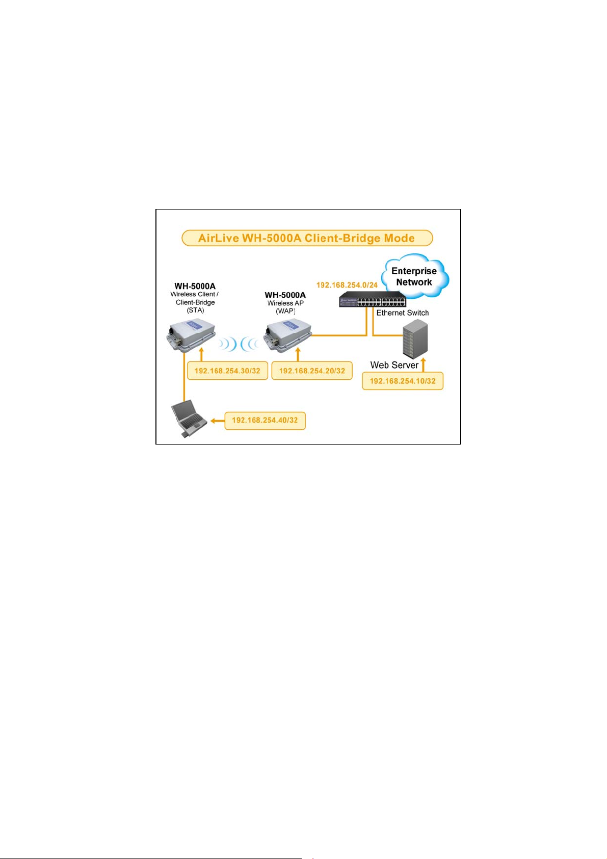
1.4 Wireless Client Mode (STA)
The AirLive WH-5000A can operate as a client device that communicates with a wireless access
point. It supports
802.11a/b/g bands. In Wireless Client mode, the WAN interface is NOT design for a
backbone network connection. It is the interface for computer connected to it. The following diagram an
example of WDS mode network topology.
There is numerous security methods provided in this mode, including WEP, WPA (TKIP and AES-CCM) and
WPA2 (TKIP and AES-CCM) are available.
1.5 Product Features
1.5.1 Basic Features
`
Single Radio Module
-
Support 802.11 a/b/g
-
Support Super G and Turbo A mode
(2.4GHz / 5GHz Band)
`
Multifunction functions:
-
Wireless Access Point (WAP)
-
Wireless Bride (WDS)
`
-
Point to Point
`
Point to Multi-Point
Wireless Client (STA) (default mode)
7 AirLive WH-5000A User’ s Manual
Page 11

1.5.2 Wireless Features
`
AP
- Disable SSID broadcast
-
MAC address filtering (MAC address Authentication)
-
Wireless client information (MAC address, Signal Strength, Transmit rate) list
-
Adjacent AP list
-
Rogue AP detection
-
Load Balancing
-
Layer 2 isolation
-
Support SNMP V1/ V2/ V3
`
Bridge
`
1.5.3 Security Features
`
`
`
`
- Point-to-Point and Point-to-Multi Point Bridge
- Bridge site map
- Adjustable ACK timing
Radio
- Support IEEE 802.11a/b/g
- Adjustable Radio Power
- Automatically optimal channel selection in 2.4GHz frequency band
Configuration through HTTPS/TLS secure web
AP
- WEP: (64-bit, 128-bit and 152-bit)
- WPA
n
Pre-shared key
n
TKIP/AES-CCMP
- WPA2 (802.11i)
- MAC based authentication (MAC address filtering)
- In band Rouge AP detection
Bridge
- AES-CCMP for wireless (128 bits)
Client
- WEP: (64-bit, 128-bit and 152-bit)
- WPA
n
Pre-shared key
n
TKIP/AES-CCMP
- WPA2 (802.11i)
WH-5000A Serials User Guide
8 AirLive WH-5000A User’ s Manual
Page 12

1.6 Radio Characteristic
`
802.11b
- Frequency band:
- Data Rate:
- Modulation:
- Transmit Output Power (Typical):
n
American (FCC): 2.412 ~ 2.462GHz (11 channels)
n
Europe (ETSI): 2.412 ~ 2.472GHz (13 channels)
n
1, 2, 5.5, 11Mbps
`
Direct Sequence Spread Spectrum (DSSS)
n
Differential Binary Phase Shift Keying (DBPSK) at 1 Mbps
n
Differential Quadrature Phase Shift Keying (DQPSK) at 2Mbps
n
Complementary Code Keying (CCK) at 5.5 and 11 Mbps
n
18 dBm for all rates
Note: Maximum power setting will vary according to individual country regulations.
!
- Receive Sensitivity (Typical):
n
-93dBm at 1Mbps
n
-88dBm at 11Mbps
`
802.11g
- Frequency band:
`
American (FCC): 2.412 ~ 2.462GHz (11 channels)
`
Europe (ETSI): 2.412 ~ 2.462GHz (13 channels)
- Data rate:
`
`
- Modulation:
`
`
`
`
`
6, 9, 12, 18, 24, 36,48, 54 Mbps
72, 96, 108 Mbps (Super G mode)
Orthogonal Frequency Divisional Multiplexing (OFDM)
BPSK at 6 and 9 Mbps
QPSK at 12 and 18 Mbps
16-quadrature amplitude modulation (QAM) at 24 and 36Mbps
64-QAM at 48 and 54Mbps
- Transmit Output Power (Typical):
`
18 dBm at 6 ~ 24Mbps
`
18 dBm at 36Mbps
`
17 dBm at 48Mbps
`
16 dBm at 54Mbps
WH-5000A Serials User Guide
Note: Maximum power setting will vary according to individual country regulations.
!
- Receive Sensitivity (Typical):
n
-89dBm at 6Mbps
n
-73dBm at 48Mbps
n
-70dBm at 54Mbps
9 AirLive WH-5000A User’ s Manual
Page 13

WH-5000A Serials User Guide
`
802.11a
- Frequency band
`
5.25 ~ 5.35GHz/5.725 ~ 5.825GHz
Note: Frequency band setting will vary according to individual country regulations.
!
- Data rate:
`
`
- Modulation:
`
`
`
`
`
- Transmit Output Power (Typical):
`
`
`
`
!
- Receive Sensitivity (Typical):
n
n
n
6, 9, 12, 18, 24, 36,48, 54 Mbps
72, 96, 108 Mbps (Super A mode)
Orthogonal Frequency Divisional Multiplexing (OFDM)
BPSK at 6 and 9 Mbps
QPSK at 12 and 18 Mbps
16-quadrature amplitude modulation (QAM) at 24 and 36Mbps
64-QAM at 48 and 54Mbps
18 dBm at 6 ~ 24Mbps
16 dBm at 36Mbps
15 dBm at 48Mbps
14 dBm at 54Mbps
Note: Maximum power setting will vary according to individual country regulations.
-84dBm at 6Mbps
-70dBm at 48Mbps
-68dBm at 54Mbps
1.7 LED indicator definition
Power
WAN
WLAN
LED
If this light is on, the unit is on;
If
it is
If this light is on, the unit is connected to network
If it is off, the unit does not have an active connection to network
The light is on for indicate the WLAN is active.
The light is blinking to indicates data transmission
1. LED blink slowly (every 1 second): there is a connection and signal quality is poor
2. LED blink fast: there is a connection, and the signal quality is good
3. LED steady: there is connection, and the signal quality is excellent
1.8 Operation Temperature
`
0 degree ~ 50 degree C
not on, the unit is off
Description
10 AirLive WH-5000A User’s Manual
Page 14

1.9 Appearance
`
RJ45 x1
`
SMA antenna connector x1
`
Reset Button
`
LED indictor x3 – Power, WAN, WLAN
`
DC IN jack
WH-5000A Serials User Guide
11 AirLive WH-5000A User’s Manual
Page 15

WH-5000A Serials User Guide
Chapter 2 Start to Configuration
The manual deals only and specifically with the single WH-5000A device as a unit. The purpose of this
chapter is the description of the device and its identifiable parts so that the user is sufficiently familiar to
interact with th e physical unit. Preliminary setup information provided below is intended for information and
instruction of the wireless LAN system administration personnel.
It is intended, and is the philosophy of the manufacturer, that the user not be required to open the individual
Any maintenance required is limited to the external enclosure surface, cable connections and to the
unit.
management
software only. A failed unit should be returned to the manufacturer for maintenance.
2.1 Before Configuration
The WH-5000A is designed to be attached to the wall at appropriate locations. To complete the
configuration, you should have at least the following components:
`
PCs with one of the following operation systems installed: Windows NT 4.0, Windows
2000 or
`
`
`
Windows XP;
A compatible IEEE 802.11a/b/g PC card or device for each computer that you wish to wirelessly
to
connect
your wireless network;
Access to one laptop or PC with an Ethernet card and cable that can be used to complete the initial
of
configuration
the unit;
A Web browser program, such as Microsoft Internet Explorer 5.5 or later, or Netscape 6.2 or later,
installed on the PC or laptop you will be using to configure the Access Point
After prepare above components, you may need the following information to login configure web pages:
`
Default IP address of the AirLive WH-5000A (192.168.254.254)
`
Default Username and Password are:
-
Username: airlive
-
Password: airlive
`
The appropriate encryption key.
If you need to change WH-5000A IP later, you may need following information:
`
IP address – a list of IP addresses available on the organization's LAN that are available to be used
`
IP address – a list of IP addresses available on the organization's LAN that are available to be used
assignment to the AirLive WH-5000A
for
`
Subnet Mask for the LAN
`
DNS IP address
If you need to use bridge mode or MAC address filtering function, you may need following information:
`
The MAC addresses of all the wireless cards that will be used to access the AirLive WH-5000A
network of access points
12 AirLive WH-5000A User’s Manual
Page 16
WH-5000A Serials User Guide
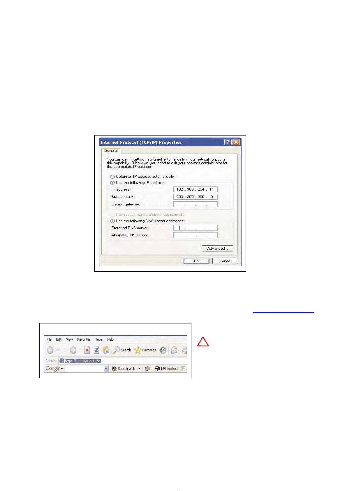
2.2 Computer’s IP setting
Plug one end of a CAT5 Ethernet cable to the RJ45 connector of the WH-5000A and the
other end to the Ethernet port on your computer. In order to connect properly to the AirLive WH-5000A
on the WAN port, the TCP/IP parameters on your laptop/PC must be set to a static IP address. Go to
your network connection settings and modify your laptop/PC’s LAN connection TCP/IP properties.
Set the IP address and subnet mask. The IP address can be in the range of 192.168.254.xxx, where xxx can be
from 2 to 199.
Now you can open a browser and connect to the AirLive WH-5000A to begin configuring the unit.
2.3 Login
On your computer, pull up a browser window and put the default URL https://192.168.254.254
for the WH-5000A in the address line.
!
The Login window appears.
Be sure that you use the https prefix,
not
Note:
http
13 AirLive WH-5000A User’s Manual
Page 17

WH-5000A Serials User Guide
It will be asked for your User Name and Password. The default User Name is "
"
airlive" to
give full access for setup configuration. The ID and Password are case sensitive.
airlive"
with the password
The default ID and Password initially installs and configures the AirLive WH-5000A after which the password
should be changed from the default password.
!
1.
2.
3.
14 AirLive WH-5000A User’s Manual
Note:
If
your login session is in-active for more than 10 minutes, then you will have to re-authenticate your
identity.
If
re-authenticate, your account will be locked.
Please refer to Chapter 8 to get more detail information. The username list in Crypto Officer
Role group is the only role that can unlock locked account. Once the account has been locked,
use the username and password
web
status. If an account is locked, it will show a status of "
Then, click the “
show status as "
the login username does not list in Crypto Officer Role group and then three times you fail to
There are two kind of user roles for WH-5000A, crypto officer and administrator.
page.
of
Clicking
unlock “button at the end of the user entry to unlock it. Other none-lock accounts
Active"
Admin
and reason "
User Management—List,
Norma
Crypto
l".
Officer
Locked"
Role
to
all Users screen displays account
and a reason of "
log
in
configuration
bad passwd".
Page 18

WH-5000A Serials User Guide
If the login username and password are correct, the following figure will be showed.
The default operation mode is Client mode.
can select Wireless Access Point
You
or Wireless Bridge mode at System
–
Configuration
to
AP or
Bridge mode
Operation mode to switch
15 AirLive WH-5000A User’s Manual
Page 19

WH-5000A Serials User Guide
2.4 Forget username, password and IP
How can you do if you had changed username, password and IP but you forget it? You can find there is a
button at front plane. Press this button over 8 seconds, the unit will go back as factory default setting.
Reset
username and password will back to “
The
and
operation mode as Client Mode.
airlive”
and “
airlive”,
and the IP will be back to 192.168.254.254
16 AirLive WH-5000A User’s Manual
Page 20

WH-5000A Serials User Guide
Chapter 3: System Configuration
The chapter describes how to do System Configuration. If you don’t know how to enter configuration screen,
2
chapter
There are three options under System Configuration:
• General
• Operating Mode
• WAN
describes how to do it.
Each screen is described in detail in the following subsections.
3.1 System Configuration – General
Click the entry on the left hand navigation panel for enter System Configuration -General.
to the System Configuration – General page.
This screen lists the software version number for your WH-5000A and allows you to set the Host Name
and
This directs you
Domain Name as well as establish
system date and time.
`
Description:
`
Host and Domain Name: Both
set at
the
`
System Time: You can manual
key in
the
WH-5000A
is
keep date and time data. It can
keep system date and time data for
5 days.
with RTC chip to
!
Note: The Crypto Officer is the only
system date must be set to a date after 01/01/2005.
user who can set the date and time. The
`
Login Banner: You can modify the terms and conditions login banner on the login screen. The default is
"This device is for authorized use only. Any unauthorized use of this product is prohibited."
When
you are satisfied with your changes, click Apply.
17 AirLive WH-5000A User’s Manual
Page 21

WH-5000A Serials User Guide
3.2 System Configuration – Operating Mode
Click the entry on the left hand navigation panel for System Configuration – Operating Mode.
you
to
the System Configuration – Operating page.
Select the radio of Wireless Access
Point, Wireless Bridging or Wireless Client to
switch
WH-5000A to AP, Bridge or Client
mode and press Apply button.
This screen allows you to set the
operating mode to Wireless Access
Point, Wireless Bridge or Wireless
Client mode. You only need to visit this
page if you will be changing modes. Note
that if you change modes your configuration
will be lost.
This directs
3.3 System Configuration – WAN
Click the entry on the left hand navigation panel for System Configuration – WAN.
System Configuration – WAN page.
This directs you to the
`
Static IP
The default setting of WAN port IP is “Specify
static
a
input
IP
the information that the AP
address”.
You
need
requires in order to allow the WH5000A
access to the wired LAN. This
will be the IP address, Subnet Mask,
Default
Gateway, and, where needed,
DNS1 and 2. The default WAN port value is
IP Address: 192.168.254.254,
Subnet
Default
Mask: 255.255.255.0,
Gateway: 192.168.254.1.
Static IP
!
Note: After changing the network address you will no longer be able to access the above configuration
page with the default IP address. You will have to change the browser URL to reflect the new IP
address and log in again.
18 AirLive WH-5000A User’s Manual
Page 22

WH-5000A Serials User Guide
`
Dynamic IP
You also can choose “Using DHCP to get an IP address”. By this way, the WH-5000A will get an IP address
from
DHCP server.
!
Apply. To
Dynamic IP
Note: If DHCP is selected, a new IP address would be given to the AirLive WH-5000A unit after clicking
log into to unit and keep setting it up, the new IP address needs to be obtained
from your
Network Administrator. There are two ways to obtain the new IP address:
1.
setting up WAN using DHCP to obtain new IP address. Remote logging allows you to
forward the syslog data from each machine to a central remote logging server. Thus, you
can get new IP from logging server. Please refer to Chapter 11.3 to get more detail
information.
Using WH-5000A embedded Remote Logging function. Set up “Remote Logging” before
2.
Using “Wireless Node Discovering Tool” that is provided by Ovislink and put in CD-ROM.
This program will discover the IP of Ovislink AP products. Please refer to Appendix B to
understand how to install it.
Click Apply to accept changes.
19 AirLive WH-5000A User’s Manual
Page 23

WH-5000A Serials User Guide
Chapter 4: Wireless Access Point Configuration
This chapter describes the items about set up AP function. Those items are under the Wireless Access Point
Configuration
Please
The following screens are available in AP mode:
• Wireless Access Point
• Service Settings
• Monitoring/Reports
4.1 Select Operation Mode
The default operation mode is Client mode. You can select Wireless Access Point mode at System
Configuration – Operation mode to switch to AP mode.
Click the entry on the left hand navigation panel for System Configuration – Operation Mode.
menu. If you don’t know how to enter configuration screen, chapter 2 describes how to do it.
keep in mind that you need click Apply to save all settings.
– General
– Security
– MAC Address Filtering
– Rogue AP Detection
– Advanced
– DHCP Server
– Wireless Clients
– Adjacent AP List
– DHCP Client List
This directs
to
you
the System Configuration – Operation Mode. Select the radio of Wireless Access Point and press
Apply button. The device will
Be reboot and then
change the operation
function.
Note that if you change
modes your configuration will be
lost.
mode as AP
20 AirLive WH-5000A User’s Manual
Page 24

WH-5000A Serials User Guide
4.2 Wireless Access Point – General
Click the entry on the left hand navigation panel for Wireless Access Point – General.
the
Wireless Access Point – General page.
There are five options under Wireless Access Point:
`
General
`
Security
`
MAC Address Filtering
`
Rogue AP Detection
`
Advanced
This directs you to
Those setup items allow your computer’s WLAN Card to communicate with the access point.
4.2.1 MAC address
The MAC address list here is AP’s wireless interface.
4.2.2 SSID
If you will be using an SSID for a wireless LAN, enter it here and in the setup of each wireless client. This
nomenclature
has to be set on the AP and each wireless device in order for them to communicate.
21 AirLive WH-5000A User’s Manual
Page 25

WH-5000A Serials User Guide
4.2.3 Wireless Mode
Select the wireless mode from the drop-down list. You can choose 802.11b, 802.11g,
802.11g Super,
802.11b/g Mixed, 802.11a or 802.11a Turbo
`
802.11b:
The 802.11b will accommodate legacy
system and support 1, 2, 5.5 and 11Mbps data
rate.
`
802.11g:
The 802.11g support data rates up to 54Mbps (6,
9,
2.4GHz frequency band by using the
802.11a OFDM techniques.
limits
only 802.11g clients. If you make sure
all of WLAN devices are 802.11g clients,
then you can chooses 802.11g mode to gain a
higher performance.
`
802.11b/g Mixed
12,
use
18,
24,
to
36,
48,
54Mbps)
This
at
mode
those WLANs that have
The 802.11b/g Mixed allows you to use both 802.11b and 802.11g clients. At
this mode, all transmissions will be at the highest data rates available if the environment is with only
802.11g devices. However, if an 802.11b device links to this network, the header information needs
to back down to
802.11b rates for all of 802.11g and 802.11b devices. It will little slow down the network throughput.
`
802.11g Super
The 802.11g Super mode can support data rate up to 108Mbps (72, 96, 108 Mbps). Although you can
gain
a
highest data rate, you need to use this function carefully because it occupies large bandwidth
may corrupt the adjacent channels’ radio signal.
and
!
Note: Super G’s channel bonding feature can significantly degrade the performance of neighboring
2.4GHz WLANs. Moreover, Super G doesn’t check to see if 11b or 11g standardcompliant devices
`
802.11a
are in range before using its non-standard techniques.
The 802.11a mode can support data rate up to 54Mbps (6, 9, 12, 18, 24, 36, 48, 54Mbps) at 5GHz
frequency
over the
band. The use of 5-GHz frequency band provides some distinct advantages
2.4GHz band. In addition to providing a greater amount of bandwidth and non-overlapping channels for
transmission,
in the 2.4GHz band (Bluetooth, cordless telephone, microwave ovens, and so on)
the 5-GHz band has less potential interference because lots of wireless device working
`
802.11a Turbo
The 802.11a Turbo mode can support data rate up to 108Mbps (72, 96, 108 Mbps).
22 AirLive WH-5000A User’s Manual
Page 26

WH-5000A Serials User Guide
4.2.4 Channel Number
The channel number is a means of assigning frequency that device uses it to transmit/receive data. Before
setting the channel in 2.4GHz band, you had better to use the optimal channel function to detect the
you
environment’s
`
Optimal channel
When the device runs on 2.4GHz band, you can use the
“optimal channel” to figure out which channel is the best
for using. Clicking on the button “
one
channel”
enter
this function, the WH-5000A detects the
environment’s radio signal at each channel and
show them at this screen. This action does not
select the channel for you but shows you what
will most probably be channel selected if you
leave the following dropdown menu at Yes.
radio signal and choose the best one for using.
, a popup screen will display the choices. After
Select the optimal
`
Auto
When channel number set up as Auto, the WH-5000A will select the optimal channel at boot up
`
802.11b, 802.11g and 802.11b/g Mixed mode
There are 11 (13 for ETSI) channel numbers that may be assigned. Because the 802.11b signal bandwidth
is 22MHz, there are 3 non-overlapping channels for 802.11b at 2.4GHz ISM band.
To reduce the interference problem, you may be able to establish up to 3 wireless networks at the same
area. If you need establish 3 wireless networks, you may assign channel number 1 to the first wireless
network. Then the channel 6 will be better for second wireless networks and channel 11 will be the third one.
airlive
23 AirLive WH-5000A User’s Manual
Page 27

WH-5000A Serials User Guide
`
802.11g Super
The 802.11g Super mode occupies larger frequency bandwidth. To avoid interfere another wireless network
operation;
it is
fixed at channel 6.
airlive
`
802.11a
The frequency band of IEEE 802.11a will vary according to individual country regulations. The
following picture shows the channel at 5GHz frequency band that WH-5000A supports at 802.11a mode.
`
802.11a Turbo
The following picture shows the channel at 5GHz frequency band that WH-5000A supports at 802.11a
Turbo mode.
airlive
airlive
24 AirLive WH-5000A User’s Manual
Page 28

WH-5000A Serials User Guide
4.2.5 TX Power Mode
The Tx Power Mode let you can set
the radio power as you wanted. It defaults to Auto,
giving the larger range of radio transmission
available under normal conditions. As an
option, the AP’s cover range can be limited by
setting the TX Power Mode to Fixed and
choosing from 1~8 for fixed power level (1
being the shortest distance.) Finally, if you want to
prevent any radio frequency transmission, set Tx
Pwr Mode to off.
4.2.6 Advanced Option
There are a number of advanced options described in the following chart:
Advanced Options
Item
Beacon interval 0 ~ 4095
beacon
is
RTS Threshold 0 ~ 3000
boundary.
DTIM
Basic Rate
Preamble
Broadcast SSID Enabled/Disabled When disabled, the AP hides the SSID in outgoing beacon frames
Parameter
1~65535 The number of beacon intervals between successive Delivery Traffic
Identification
802.11b
1 and 2 Mbps
1, 2, 5.5 and 11Mbps
802.11a, 802.11g, 802.11b/g mixed
1 and 2 Mbps 1, 2,
5.5 , 6 , 11, 12, and
24 Mbps
Short/Long
Preamble
The
frequency
transmitted by AP
The number of bytes used for the RTS/CTS handshake
When a packet size is greater than the RTS threshold, the RTS/CTS
handshaking is performed
Maps (DTIMs). This feature is used for Power Save Mode
The basic rates used and reported by the AP. The
highest rate
specified
transmitting broadcast/multicast and management frames
The basic rates used and reported by the AP. The
highest rate
specified
transmitting broadcast/multicast and management frames
Specifies whether frames are transmitted with the Short or
Long
Preamble.
and client can not obtain the SSID through passive scanning.
Also, when it is disable, the AP doesn’t send probe
responses to probe requests with unspecified SSIDs.
in
is
is
the
the
Description
milliseconds
rate
rate
that
that
in
the
the
which
the
AP
AP
uses
uses
802.11
when
when
25 AirLive WH-5000A User’s Manual
Page 29

WH-5000A Serials User Guide
4.3 Wireless Access Point – Security
Click the entry on the left hand navigation panel for Wireless Access Point – Security.
Wireless Access Point – Security page.
the
proceed to BYPASS mode?” Click OK to enter BYPASS mode with no encryption setting.
This directs you to
The WH-5000A will display a default factory
setting of no encryption, but fore security reasons will
not communicate to any clients unless the encryptions set
by administrator. You must select the wireless
encryption that you want to use and click Apply. If
want to leave the encryption set to No Encryption,
chooses “None” and clicks Apply.
dialog box will ask “are you sure you want
to
you
A popup
4.3.1 Static WEP
WEP (Wired Equivalent Privacy) was originally designed to provide the same level of security for wireless
as
LANs
some
access
Shared Key,
appropriate. ".
That same WEP key must also be set on each wireless clients those are to become part
of the wireless network. For greater security, set authentication type to “shared Key, and if "shared
key" is accepted, then each wireless device must also be coded for "shared key”.
that of a wired LAN but is not now state-of-the-art. But the use of WEP encryption can still provides
measure of security. WEP relies on the use of identical static keys deployed on client stations and
points. In WEP, you can set the Authentication Type for Open System,
`
Key Generator:
or
Open/Shared.
Select 64.bit, 128bit or 152.bit encryption and enter the WEP key as
The “Key generator” function generates
the appropriate length automatically. The key is initially shown in plain text so the user
has the opportunity to copy the key. Once the Key is applied, there
displayed
in plain text.
a
randomized encryption key of
is no
longer
26 AirLive WH-5000A User’s Manual
Page 30

WH-5000A Serials User Guide
4.3.2 802.11i and WPA
`
WPA
WPA (Wi-Fi Protected Access) was designed to enable use of wireless legacy systems employing
WEP
while improving security. WPA uses improved data encryption through the Temporal Key Integrity Protocol
(TKIP) ensures that the keys haven’t been tampered with. In addition, user authentication is enabled using
Extensible Authentication Protocol (EAP).
the
For enhanced security, you can enable IEEE 802.1x authentication, which provides authenticated access to
802.11 wireless networks. IEEE 802.1x authentication minimizes wireless network security risks, such as
unauthorized
centralized
access to network resources and eavesdropping. It provides user and computer identification,
authentication, and dynamic key management. The support that IEEE 802.1x
provides for Extensible Authentication Protocol (EAP) security types allows you to use authentication
methods such as smart cards and certificates .Using 802.1x function, you need to install a separate
certification system, such
as Radius Server, for key management and authentication requires and each client must have been issued
authentication certificate.
an
- Pre-Share Key or 802.1x:
If you don’t have Radius Server, selecting pre-shared key. Simply input up to 63
character
/numeric /hexadecimals in the Passphrase field. If your clients use WPA-TKIP select TKIP as
encryption
type. If your clients use WPA-AES, select AES-CCMP.
If you have installed Radius Servers, select WPA 802.1x and input the Radius Server setting.
- TKIP or AES-CCMP:
TKIP
scrambles
hashing algorithm
integrity-checking
keys
using
a
and, by adding an
feature,
ensures
that the keys haven't been tampered with.
The TKIP improves security
especially
for legacy hardware whose implement
WEP encryption engine.
The AES-CCMP is a stronger encryption
algorithm
support
can
wireless
for newer hardware. If the clients
this new encryption algorithm, you
use it to enhance the security of
network.
27 AirLive WH-5000A User’s Manual
Page 31

WH-5000A Serials User Guide
`
802.11i (WPA2)
The IEEE 802.11i is a new standard that enhances the 802.11 MAC security and authentication by stronger
encryption,
Wi-Fi Alliance base on the IEEE 802.11i and runs a certification program that grants the WPA2 brand
the
based
Besides the Pre-authentication function, setting WP A2 is most same as WPA,
authentication, and key management. The WPA2 and 802.11i are virtually identical. The WPA2 is
on
equipment’s support of the important feature of 802.11i.
- Pre-authentication
Enable pre-authentication to allow a client to authenticate in advance with the AP
before the client is associated with it. Allowing the AP to pre-authenticate a client decreases
the transition time when a client roams between APs.
Once you have selected the options you will use, click Apply to save all setting.
4.4 MAC Address Filtering
Click the entry on the left hand navigation panel for Wireless Access Point – MAC Address Filtering.
directs
you to the Wireless Access Point – MAC Address Filtering page.
The factory default for MAC Address filtering is Disabled. If
also
set the toggle for Filter Type. This works as follows:
`
If Filtering is enabled and Filter Type is
“
Deny AII Except Those Listed
Below
”, only those
with the authorized MAC addresses will
be able to communicate with the AP. In
this case, input the MAC addresses of all
the PC cards that will be authorized to
access this AP.
`
If Filtering is enabled and Filter Type is
“
Allow AII Except Those Listed Below
those
devices with a MAC address
which has been entered in the MAC Address
listing will NOT be able to communicate
with the AP.In this case, navigate to the
report: Wireless Clients and copy the MAC
address of any wireless Client that you want
to exclude from communication with the AP
and input those MAC Addresses to the MAC
Address list.
devices equipped
This
you enable MAC Address filtering, you should
”,
28 AirLive WH-5000A User’s Manual
Page 32

WH-5000A Serials User Guide
4.5 Rogue AP Detection
Click the entry on the left hand navigation panel for
Wireless Access Point – Rouge AP
Detection
. This directs you to the Wireless
Access Point – Rouge AP Detection page.
This function allows the network administrator
to detect
rogue
in
AP detection and enter the MAC Address of
band
rogue
AP.
each AP in the network that you want the AP being
configured to accept as trusted AP (You may add up
to 20 APs). Enter an email address for notification of
any rogue or non- trusted APs when WH-5000A
find it. You can
also select the following filter options.
Enable
`
SSID Filter: Check the SSID option to only
send rogue APs that match the AP's SSID or wireless bridge's SSID.
`
Channel Filter: Check the channel filter option to only send rogue APs that match the AP's channel or
the
wireless bridge's channel.
`
If both options are checked, only APs that match both the SSID and channel are sent.
The Adjacent AP lists under Monitoring/Reports on the navigation menu, will detail any APs’ information.
4.6 Wireless Access Point – Advanced
Click the entry on the left hand navigation panel for Wireless Access Point – Advanced.
the
Wireless Access Point – Advanced page. The Advanced page allows you to enable or
disable load balancing and Layer 2 Isolation.
4.6.1 Load Balancing
Load balancing is enabled by default to distribute
efficiently among network servers so that no
traffic
individual
two
room,
APs,
server is overburdened. For example, if
APs with similar settings are in a conference
depending on the location of the
all wireless clients could potentially
associate with the same AP, leaving the
other AP unused. Load balancing
to evenly
both APs.
distribute
the wireless clients on
attempts
This directs you to
29 AirLive WH-5000A User’s Manual
Page 33

WH-5000A Serials User Guide
4.6.2 Publicly Secure Packet Forwarding
The Publicly Secure Packet Forwarding selection item is the Layer 2 Isolation function. Layer 2 isolation
prevents
wireless clients that associate with the same AP from communication with each other.
4.7 DHCP Server
If you will be suing DHCP Server function, click the entry on the left hand navigation panel for Services
Setting
DHCP
–
SNMP Server.
server writes at Section 7.1.
This directs you to the Services Setting – SNMP page. The detail description of
4.8 Monitoring Reports
If you want to understand some information about WLAN status, the entry on the left hand navigation panel
for
Monitoring/Reports
AP
List
and
Monitoring/Reports – DHCP Client List may provide that information to you.
The detail description of DHCP server writes at Section 9.4 (Wireless Clients), Section 9.5 (Adjacent AP
List) and Section 9.6 (DHCP Client List).
–
Wireless
Clients,
Monitoring/Reports
–
Adjacent
30 AirLive WH-5000A User’s Manual
Page 34

WH-5000A Serials User Guide
Chapter 5: Wireless Bridge Configuration
Wireless bridging is used to set up an independent wireless bridge connection. Since
wireless bridging provides a mechanism for AP to collaborate, it is possible to extend the
basic service set (BSS) of a standalone AP and to connect two separate LANs without installing my
cabling. The WH-5000A model support manual bridge function. The manual bridging function in the WH5000A
allows you to set a number of alternate bridging configurations.
`
Point-to-Point bridging of two Ethernet Links
`
Point-to-Multipoint bridging of several Ethernet links
`
Repeater mode
The following screens are available in Bridge mode:
• Wireless Bridge
– General
– Radio
– Encryption
31 AirLive WH-5000A User’s Manual
Page 35

WH-5000A Serials User Guide
5.1 Select Operation Mode
The default operation mode is Client mode. You can select Wireless Access Bridge mode at
System
Configuration – Operation mode.
Click the entry on the left hand navigation panel
System Configuration – Operation
for
Mode
. Select the radio of Wireless Bridging
and press
Apply button. The device will be
reboot and then change the operation mode as
Bridge function.
Note that if you change modes your configuration will be lost.
5.2 Wireless Bridge – General
Click the entry on the left hand navigation panel for Wireless Bridge - General.
the
Wireless Access Point – Bridging page.
`
Signal strength LED MAC:
Signal strength LED MAC allows you
set up
the
LED
to indicate the received bridge
signal strength
SS
(Signal
Strength)
This directs you to
(RSSI, Received Signal Strength Indication)
remote device the.
of
When you
key in the BSSID at “Add
remote’sAP BSSID/Note”
section and
click “Add”, this BSSID will be indicated
here. Choosing the
BSSID that you want to know the received signal strength, the SS LED will indicate
the signal
strength by different flicker frequency. If you don’t wish to display any connection signal, select “
Assigned”.
You need click “
Apply”
after you change this value.
32 AirLive WH-5000A User’s Manual
Not
Page 36

WH-5000A Serials User Guide
`
Spanning Tree Protocol (STP) 802.1d:
It should be enabled if there is any possibility that a bridging loop could occur. If you are certain that
there
is no
possibility that a bridging loop will occur, you can disable Spanning
Tree Protocol, because the bridge will be more efficient (faster) without it. However, if not sure,
the safest solution is to enable Spanning Tree Protocol.
`
Remote AP’s MAC Address
This section list the remote bridge’s information, port number, signal strength and note. Moreover, if
you
don’t want to link with some remote bridges, click the check box at the left side of port number
confirm by clicking “Delete”.
and
5.3 Wireless Bridge – Radio
Click the entry on the left hand navigation panel for Wireless Bridge - Radio.
you to the Wireless Access Point – Radio page.
`
MAC Address:
This is the MAC Address for WLAN card and as BSSID for the bridge devices at the other end that
want
to
link with this unit. The Wireless Bridging uses the BSSID for purposes of
establishing contact.
`
Wireless Mode:
Support 802.11 b/g Mixed, 802.11g Super, 802.11a and 802.11a turbo
`
Tx Rates:
When set to AUTO, the unit attempts to select the optimal rate for the channel. If a fixed rate is used,
unit will only transmit at that rate.
the
`
Channel No:
The channel number is a means of an assigning frequency that device uses it to transmit/receive
data.
The channel number should be same as the one using on the devices those will be bridge
together.
This directs
33 AirLive WH-5000A User’s Manual
Page 37

WH-5000A Serials User Guide
`
Tx Pwr Mode:
It is same as AP, support Off, Fix and Auto modes. At Fix mode, there are 5 signal levels you can
(1
select
set
`
Propagation Distance
This parameter relates to adjust the timing of
WLAN MAC. To make sure the radio signal can reach
to the device at other end, set the distance
based on the distance between this bridge and
furthest bridge that is connected to it
`
RTS Threshold
This function uses for the RTS/CTS handshake boundary. When a packet size is greater than
the RTS
threshold, the RTS/CTS handshaking is performed
being the smallest power level). If you want to prevent any radio frequency transmission,
Tx
Pwr Mode to off.
`
Add Remote’s AP BSSID/Note for manual bridging
The BSSID corresponds to that bridge’s MAC address. The Wireless Bridging uses the BSSID for
of
purposes
with
colons. Data entry is not case sensitive. You may also enter a note that defines the location of
remote bridge. Then click Add to accept.
the
establishing contact. You need to enter the BSSID of remote bridge, enter hexadecimal
5.4 Wireless Bridge – Encryption
Click the entry on the left hand navigation panel for Wireless Bridge -
Encryption
Point
.
This
– Encryption page.
directs you to the Wireless Access
This page is used to configure static encryption keys for the wireless
On
bridge.
(No
Data
Encryption) or Static AES-CCM (128 bit). The
this
screen,
you
“Key generator” function generates a
randomized
encryption key of the
appropriate length automatically. You can use
this function to get a randomized key
number from one device and use it to all
of other devices those are
bridge
network. The encryption key that
on
the
you use on this screen must be the
same for any bridge connect to
yourbridging
n
communication
etwork in order for
to
occur.
can
either
same
select
None
34 AirLive WH-5000A User’s Manual
Page 38

WH-5000A Serials User Guide
5.5 Point-to-Point Bridge Setup Guide
A point-to-point link is a direct connection between tow, and only two, locations or nodes.
For the two bridges that are to be linked to communicate properly, they have to be set up with compatible
in
commands
`
`
`
`
`
setup screens. Below is the list
Channel number:
- The bridges must have the same channel number.
- The channel number doesn’t be same as using for AP.
Wireless Mode:
- Choose 802.11g for high data rate
- Choose 802.11b for high transmit distance
Spanning Tree Protocol (802.1d):
- Enable, if there is any possibility of a bridging loop, or
- Disable, if there is no possibility of bridging loop to gain higher efficient
Bridge signal strength LED port:
- Set up the SS LED map to which remote bridge
BSSID:
- Entering remote bridge’s MAC address at the BSSID field of “Add remote AP’s BSSID/Note”
section.
may
clock
`
Encryption:
- Setting Encryption type: Off or Static AES Key
Although it is option item, entering a note that defines the location of the remote bridge
be
helpful for your management lots of remote bridges. After you key in BSSID and Note,
the “Add” to list this item at “Remote AP’s MAC Address” section.
- Each bridge must have the same encryption type. And if using Static AES Key, the key of each
must be the same.
bridge
Click Apply to accept your changes
The following Table describes the basic attributes for the network topology illustrate at above picture.
35 AirLive WH-5000A User’s Manual
Page 39

WH-5000A Serials User Guide
Table: Point to Multi Point Configuration table
Direction
Wireless Bridge - General
Spanning Tree Protocol
Wireless Bridge - Radio
Propagation distance
Wireless Bridge – Encryption
Encryption
Bridge 1
Bridge Mode
Channel
Wireless Mode
TX Power
BSSID
Bridge 1
Manual Bridge
Enable
(or Disable if no bridging loop)
4
802.11g (for high data rate)
Auto
Select appropriate value
Add Bridge 2 BSSID
(MAC address)
Select appropriate Key type and
Key.
Must be the same key
as Bridge
2
Bridge 2
Bridge 2
Manual Bridge
Enable
(or Disable if no bridging loop)
4
802.11g (for high data rate)
Auto
Select appropriate value
Add Bridge 1 BSSID
(MAC address)
Select appropriate Key type
and Key.
key
as Bridge 1
Must be the same
36 AirLive WH-5000A User’s Manual
Page 40

WH-5000A Serials User Guide
5.6 Point-to-Multipoint Bridge Setup Guide
A Point-to-Multipoint configuration allows you to set up three or more WH-5000A in
bridging mode and accomplish bridging between 3 or more locations wirelessly.
Same as Point-to-Point Bridge Setup procedure, you need to set up with compatible commands in setup
screens.
and
Using above picture as a example, Bridge 1 must contain all of the other’s BSSID, while Bridge 2
3
must contain Bridge 1’s BSSID.
The following Table describes the basic attributes for the network topology illustrate at above picture.
Table: Point to Multi Point Configuration table
Direction
Wireless Bridge - General
Bridge Mode
Spanning Tree Protocol
Wireless Bridge - Radio
Wireless Mode
Propagation distance
Channel
TX Power
BSSID
Wireless Bridge – Encryption
Encryption
Manual Bridge
Enable
(or Disable if no bridging loop)
4
802.11g (for high data rate)
Auto
Select appropriate value
Add Bridge 2 BSSID
(MAC address)
Select appropriate Key type and
Key.
as Bridge
Bridge 1
Must be the same key
2
Bridge 2~3
Manual Bridge
Enable
(or Disable if no bridging loop)
4
802.11g (for high data rate)
Auto
Select appropriate value
Add Bridge 1 BSSID
(MAC address)
Select appropriate Key type
and Key.
key
as Bridge 1
Must be the same
The above recommended setup requires only Bridge 1 to be set in point-to-multipoint mode. It is possible to
set all bridges in point-to-multipoint mode, in which case, each bridge would have to contain the BSSID for
each
of
the other bridges and Spanning Tree Protocol must be enabled.
37 AirLive WH-5000A User’s Manual
Page 41

WH-5000A Serials User Guide
5.7 Repeater Bridge Setup Guide
A repeater setup can be used to extend the wireless signal from one bridge connected to an Ethernet LAN
wirelessly so that another bridge can control a wireless LAN at a distance.
The following Table describes the basic attributes for the network topology illustrate at above picture.
Table: Repeater Configuration table
Direction
Wireless Configuration - General
Bridge Mode
Spanning Tree Protocol
Wireless Bridge - Radio
Propagation distance
Wireless Configuration – Bridging Encryption
Encryption
Channel
Wireless Mode
TX Power
BSSID
Bridge 1
Manual Bridge
Enable
(Disable if no loop)
4
802.11g (for high data
rate)
Auto
Appropriate value
Add Bridge2’s BSSID
(MAC address)
Select appropriate
Key
Key. Must
same key as Bridge 2
type
be
Bridge 2
Manual Bridge
Enable
Disable if no loop)
4
802.11g (for high data
rate)
Auto
Appropriate value
Add Bridge1’s and 3’s
BSSID(MAC address)
Select
Key
and
the
Key. Must
same key as Bridge 1
appropriate
type
be
Bridge 3
Manual Bridge
Enable
Disable if no loop)
4
802.11g (for high data
rate)
Auto
Appropriate value
Add Bridge2’s BSSID
(MAC address)
Select
Key
and
the
Key. Must
same key as Bridge 1
appropriate
type
be
and
the
38 AirLive WH-5000A User’s Manual
Page 42

WH-5000A Serials User Guide
Chapter 6: Wireless Access Client Configuration
This chapter describes the items about set up Wireless Access Client function. Those items are under the
Wireless
describes
There are two options under System Configuration:
6.1 Wireless Bridge – General
Click the entry on the left hand navigation panel for Wireless Client – General.
The
The bundle Status function
let you easy
link status. You can click
Refresh at Status Section
after WH-5000A link with AP,
and then you can get link
status information.
39 AirLive WH-5000A User’s Manual
Access Point Configuration menu. If you don’t know how to enter configuration screen, chapter 2
how to do it. Please keep in mind that you need click Apply to save all settings.
• General
• Encryption
This directs you to this page.
procedure of how to set up WH-5000A to link with AP lists as following.
1. Operation mode:
Click the entry on the left hand navigation panel for System Configuration – Operation mode.
operation mode as “
the
2. SSID:
Wireless Client”
and click Apply button.
This nomenclature of SSID has to be same as the one on the access point which WH-5000A want to
link with. The bundle Site Survey function can help you discover the APs in your environment and
choose a one to link with. To do Site Survey, click the Scan at Site Survey section.
3. Wireless Mode:
Select the wireless mode from the drop-down list. You can choose from the following options:
•
802.11b
•
802.11g
•
802.11g Super
•
802.11a
• 802.11a Turbo
4. Click Connect button.
to
understand
Select
Page 43

WH-5000A Serials User Guide
6.2 Wireless Client – Encryption
Click the entry on the left hand navigation panel for Wireless Client – Encryption.
Wireless
important
There are six options under System Configuration:
Client – Encryption page. This is used to configure the security for the wireless client. This is an
page to set up to ensure that your client is working correctly.
• Open (WEP)
• Shared (WEP)
`
WPA-PSK
`
WPA-EAP-TLS
`
WPA2-PSK
`
WPA2-EAP-TLS
This directs you to the
6.2.1 Open
This is one of WEP Authentication Type. Select None, 64-bit, 128-bit or 152 - it encryption and enter the
WEP
wireless
`
Key Generator: The “Key generator” function generates a randomized encryption key of the appropriate
key. That same WEP key must also be set on each wireless clients/AP those are to become part of the
network.
length
automatically. The key is initially shown in plain text so the
user has the opportunity to copy the key. Once the Key is applied, there is no
longer displayed in plain text.
40 AirLive WH-5000A User’s Manual
Page 44

WH-5000A Serials User Guide
6.2.1 Shared
This is one of WEP Authentication Type. Select 64.bit, 128bit or 152.bit encryption and enter the WEP key.
same WEP key must also be set on each wireless clients/AP those are to become part of the wireless
That
network.
If
the "shared” mode is selected, each wireless device must also be as "shared” mode.
6.2.2 WPA-PSK/WPA2-PSK
If the AP that WH-5000A client
mode will link with uses
WPA PSK or WPA2
function
network hasn’t installed Radius
Server, you need to select WPAPSK
Simply input up to 63
character/numeric/hexadecimals
in the Passphrase field. If the
AP uses WPA-TKIP select
TKIP as encryption type. If
the AP uses WPA-AES, select
AES-CCM.
and
or
WPA2-PSK mode.
your wireless
PSK
41 AirLive WH-5000A User’s Manual
Page 45

WH-5000A Serials User Guide
6.2.3 WPA-EAP-TLS/WPA2-EAP-TLS
The 802.1x system uses a Radius
Server
separate
authentication.
Extensible
security types allows you to use
methods such as smart cards and certificates.
WH-5000A
types.
for key management and a
certification system for
The IEEE 802.1x provides
Authentication Protocol
provides
EAP-TLS
authentication
security
(EAP)
If your wireless network have installed
Radius
WH-5000A client mode will link with uses
WPA 802.1x or WPA2 802.1x function,
Servers
and
the
you need to select WPA-EAP-TLS or WPA2-EAP-TLS.
AP
that
There are two items, Certificates and Encryption, have to be selected in order to have successful 802.1x
authentication.
e
Certificates:
They are listed as following:
To set up WPA-EAP-TLS/WPA2-EAP-TLS function, you need to get “Certification file” from certification
If
system.
you have it, then click “
Load New Certification” to
load it. The following picture appears after
click “Load New Certification”.
you
-
unsigned
is part of a public
scheme. The most common
variety
standard. Normally an
includes
authority (CA) which vouches for
correctness of the data
a
a
public
key
key infrastructure
is based on the ISO X.509
X.509
a
digital signature from a certificate
certificate. This
pem
extension.
file
certificate and
commercial
certificate
contained
should
in
have
42 AirLive WH-5000A User’s Manual
Page 46

WH-5000A Serials User Guide
-
Client Certificate:
Click
`
should have a der extension.
-
Private Key: A private key is an encryption/decryption key known only to the party or parties that
exchange
users
-
Private Key Password: Private key password encrypts your certificate's private key.
-
Login Name: Enter your user name into the Login name field. This is the name that is presented to
the
form, domain\user_name.
it is stored in the authentication database. See your network administrator for the required format.
“Update Certs”
Encryption:
Select one of encryption methods: TKIP and AES-CCM for encryption of wireless
communication between wireless client and wireless access point
secret messages. In traditional secret key cryptography, a key would be shared by the
so
that each could encrypt and decrypt messages. This file should have a pem extension.
network when you authenticate. If you authenticate against a Windows Active Directory, use the
The user certificate is generated by a trusted certificate authority (CA). This file
Otherwise, use a login name that matches the form of the user name as
button after assigning all information.
43 AirLive WH-5000A User’s Manual
Page 47

WH-5000A Serials User Guide
Chapter 7: Service Settings Menu
This chapter describes the items about Service Setting. If you don’t know how to enter configuration screen,
2
chapter
keep
Click the entry on the left hand navigation panel for Service Setting.
7.1 DHCP server
Click the entry on the left hand navigation panel for Service Setting – DHCP Server.
DHCP server page.
This page allows configuration of the DHCP server function. The DHCP server function, accessible only from
the
The default factory setting for the DHCP server function is enabled. You can disable the
describes how to do it. Please keep in mind that you need click Apply to save all settings. Please
in
mind that you need click Apply to save all settings.
This directs you to this page.
This directs you to the
Local LAN port, is used for initial configuration of the management function.
DHCP server function, if you wish. You can also set the range of address to be assigned.
WNS server: The WNS (Windows Internet Naming Service) server is used for name resolution. It is similar
in function to DNS. It allows you to search for resources by computer name instead of IP address
Lease period is for the DHCP server function. The lease times you can select are: 1 hour, 2 hours, 1 day, 2
days, or 1 week.
44 AirLive WH-5000A User’s Manual
Page 48

WH-5000A Serials User Guide
7.2 SNMP Agent
Click the entry on the left hand navigation panel for Service Setting – SNMP Agent.
SNMP Agent page.
This directs you to the
The SNMP collects and
information
system.
for use in a network management
The
agent software module translates the device
management
interpretation
usually
computer.
information into a common form for
by
the SNMP manager,
resides on a
In the current release, the SNMP agent module
support
SNMPv1,
SNMPv3. It also implements warmStart,
linkDown, linkUp, and
SNMP
configuration consists of several
fields, which are explained below:
`
Community:
The Community field for Get (Read Only), Set (Read & Write), and Trap is simply
the SNMP
terminology for “password” for those functions.
stores
management
WH-5000A integrated SNMP
which
network
administrator’s
SNMPv2C
authentication.
and
The
`
Source:
The IP address or name where the information is obtained.
`
Access Control:
Define the level of management interaction permitted.
If using SNMPv3, enter a username (minimum of eight characters), authentication type with key and data
encryption
setup.
type with a key. This configuration information will also need to be entered in your MIB manager
45 AirLive WH-5000A User’s Manual
Page 49

WH-5000A Serials User Guide
Chapter 8: User Management Menu
This chapter describes the items about User Management page. If you don’t know how to enter configuration
screen,
There are two user roles for WH-5000A, crypto officer and administrator.
chapter 2 describes how to do it.
`
Crypto Officer: The user of crypto officer role has the highest authority to set up all of functions of
WH-5000A.
`
Administrator: The user of administrator role has most of right to set up WH-5000A; however, they
can not set up the encryption function.
The WH-5000A default username is airlive (password is airlive)
you initial the configuration job.
There are two options under Admin User Management:
•
List All Users
– Edit User
•
Add New Users
Each screen is described in detail in the following subsections.
8.1 List All Users
Click the entry on the left hand navigation panel for User Management – List All Users.
this
page.
The List All Users page simply
lists all Cyrpto Officer and Administrator
accounts configured for the unit.
You can edit or delete users from this
screen.
If
you
click
on
Edit,
the
Management – Edit User Screen appears. On this screen you can edit the user ID, Password, role and note
fields.
46 AirLive WH-5000A User’s Manual
Admin
User
and its role is crypto officer role to allow
This directs you to
Page 50

WH-5000A Serials User Guide
8.2 Add New User
Click the entry on the left hand navigation panel for User Management – Add New User.
this
page.
The Add New User screen allows you to
add new Crypto
assigning
The password can not be less than 8 characters.
After you key in user ID, password, and choose Role,
click Add to add this new user.
and confirming the password for each.
Officer
or
Administrators,
This directs you to
47 AirLive WH-5000A User’s Manual
Page 51

WH-5000A Serials User Guide
Chapter 9: Monitoring/Reports Menu
This chapter describes the items about Monitor/Reports page. If you don’t know how to enter configuration
screen,
chapter 2 describes how to do it.
There are three options under Montioring/Reprots when the operation mode is Wireless
Bridging and
Wireless Client
`
`
`
System Status
Bridging Status
Bridging Site Map
There are three options under Montioring/Reprots when the operation mode is Wireless
Bridging and
Wireless Client
`
`
`
`
`
`
System Status
Bridging Status
Bridging Site Map
Wireless Clients
Adjacent AP List
DHCP Client List
9.1 System Status
Click the entry on the left hand navigation panel for Monitor/Reports – System status.
this
page. This screen displays the status of the WH-5000A device and network interface details and the
routing table.
There are also some pop-up informational menus on this screen that give detailed information about CPU,
PCI,
Interrupts, Process and Interfaces.
This directs you to
48 AirLive WH-5000A User’s Manual
Page 52

9.2 Bridging Status
WH-5000A Serials User Guide
Click
the
entry
on
panel
for
Monitor/Reports –Bridging Status.
screen displays the Ethernet Port STP status, wireless port
STP status, and wireless bridging information.
the
left
hand
navigation
This
9.3 Bridge Site Map
Click the entry on the left hand navigation panel for Monitor/Reports – Bridge Site Map.
This screen displays the graphology of Bridges Network topology with some useful information – IP, Signal
Strength and so on.
The map shows the network layer-2 topology. APs that are part of another network are not displayed in the
The root STP node is always on top and the nodes of the hierarchy are displayed below it. Wired links
map.
double dotted lines and wireless links are single dotted lines. This map does not update dynamically. You
are
press the Update button to refresh the map.
must
49 AirLive WH-5000A User’s Manual
Page 53

WH-5000A Serials User Guide
9.4 Wireless Clients
Click the entry on the left hand navigation panel for Monitor/Reports – Wireless Client.
This screen displays the MAC address of all wireless clients and their signal strength and transmit rate.
9.5 Adjacent AP list
Click the entry on the left hand navigation panel for Monitor/Reports – Adjacent AP List.
This screen displays the detected APs, BSSID(MAC address), SSID, Channel, Signal Strength,
Operation Type, Age and WEP status.
These APs are detected by the AP's wireless card. The lists of APs are only within the band that can be seen
a
particular channel. For example, if the AP is on channel 1, it will display APs on channels 1-3.
from
If you select the check box next to any AP shown, the AP will thereafter be accepted by the AirLive WH-
as
5000A
a trusted AP.
9.6 DHCP Client List
Click the entry on the left hand navigation panel for Monitor/Reports – DHCP Client List.
This directs you
50 AirLive WH-5000A User’s Manual
Page 54

to this page.
WH-5000A Serials User Guide
The DHCP client list displays all clients currently connected to the WH-5000A via DHCP server, including
their
hostnames, IP addresses, and MAC addresses.
The DHCP Client list constantly collects entries. To remove entries from the list, check mark the Revoke
Entry selection and click Remove to confirm the action.
51 AirLive WH-5000A User’s Manual
Page 55

WH-5000A Serials User Guide
Chapter 10: Logs
This chapter describes the items about Monitor/Reports page. If you don’t know how to enter configuration
screen, chapter 2 describes how to do it.
There are two logs, system log and web access log, available for viewing and exporting.
10.1 System Log
Click the entry on the left hand navigation panel for Logs – System Log.
The
system
are
messages documenting functions performed internal to system, based on the system’s
functionality. Generally, the network administrator would only use this information if trained as or
working with a field engineer or as information provide to technical support. The system log will continue
to accumulate listing. If you wish to export listings, use the Export button.
log
display
system-facility-messages
with
This directs you to this page.
date
and
time
stamp.
There
52 AirLive WH-5000A User’s Manual
Page 56

WH-5000A Serials User Guide
10.2 Web Access Log
Click the entry on the left hand navigation panel for Logs – Web Access Log to enter this page.
This screen displays system facility messages with date and time stamp for any actions
involving web access. For example, this log records when you set encryption mode, change operating
mode, etc., using the web browser. It establishes a running record regarding what actions were performed
and by whom. The Web Access Log will continue to accumulate listing. If you wish to export listings, use the
Export button.
53 AirLive WH-5000A User’s Manual
Page 57

WH-5000A Serials User Guide
Chapter 11: System Administration Menu
This chapter describes the items about System Administration page. If you don’t know
how to enter configuration screen, chapter 4 describes how to do it.
There are five options under System Administration:
`
System Upgrade
-
-
`
Factory Default
`
Remote Logging
`
Reboot
`
Utilities
Firmware Upgrade
Local Configuration Upgrade
11.1 System Upgrade
Click the entry on the left hand navigation panel for System Administration – System Upgrade to enter
this
page. It provides the ability to upload to the WH-5000A device’s firmware as they become available.
When a new upgrade file becomes available, you can do a firmware upgrade from the Firmware Upgrade
window.
There is also a configuration file transfer option which allows the system configuration file from one AP to be
transferred
that
are
transfers.
to
another AP, in order to minimize the administration of the APs. Only configuration parameters
can be shared between APs are downloaded in the configuration file. WAN IP address and hostname
not transferred in the configuration file. Click on the Local Configuration Upgrade tab to perform file
Only the Crypto Officer role can access this function.
11.1.1 Firmware Upgrade
On the System Administration – System Upgrade screen, the Firmware Upgrade tab is the default view.
browse and select the firmware file to be uploaded. Click on the Upload Firmware button.
Click
54 AirLive WH-5000A User’s Manual
Page 58

WH-5000A Serials User Guide
11.1.2 Location Configuration Upgrade
On the System Administration – System Upgrade screen, click on the Local Configuration Upgrade tab
to upload and download configuration files to APs connected to the network.
To upload a configuration file, select the file using the browse button and enter the passphrase for that file.
passphrase protects the file from unauthorized users. It prevents unauthorized user from applying the
The
system
downloading the system configuration file to a local computer, the use must enter a passphrase to protect
the file. Before the system configuration file can be uploaded onto another WH-5000A, the passphrase
must be entered on the remote WH-5000A.
The configuration file can be tagged with a 12 character tag to keep track of the configuration file as it is
transfer
configuration file to an unauthorized AP to gain access to the network. Before
to
other AirLive WH-5000A devices.
55 AirLive WH-5000A User’s Manual
Page 59

WH-5000A Serials User Guide
11.2 Factory Default
Click the entry on the left hand navigation panel for System Administration – Factory Default to enter this
page.
The “
Restore”
settings.
button is a fallback troubleshooting function that should only be use to reset system to original
Only the Crypto Officer role has access to the Restore button.
11.3 Remote Logging
Click the entry on the left hand navigation panel for System Administration – Remote Logging to enter
page.
this
Remote logging allows you to forward the syslog data from each machine to a central remote logging server.
In the WH-5000A, this function uses the syslogd daemon. You can find more information
about syslogd by searching for “syslogd” in an Internet search engine (such as Google®) to find a versin
compatible with your operation system.
If you enable Remote logging, input a System Log Server IP Address and System Log Server Port, click
Apply to accept these values.
56 AirLive WH-5000A User’s Manual
Page 60

WH-5000A Serials User Guide
11.4 Reboot
Click the entry on the left hand navigation panel for System Administration – Reboot to enter this page.
The
Reboot utility allows you to reboot the WH-5000A without changing any preset functionality. Both
Crypto Officer and Administrator roles have access to this function.
11.5 Utilities
Click the entry on the left hand navigation panel for System Administration – Utilities to enter this page.
This
screen gives you ready access to two useful utilities: Ping and Trace route. Simply enter the IP address
or hostname you wish to ping or trace route and click either the Ping or Traceroute button, as appropriate.
57 AirLive WH-5000A User’s Manual
Page 61

WH-5000A Serials User Guide
Chapter 12: Reset and Rest to Factory Default Setting
The WH-5000A is with two kind of reset behavior. One is reset system without changing any preset
functionality and the other one is reset system to factory default settings that will change any preset
functionality. There are two ways to do reset function. One is by enter configure screen (introduce at
chapter 11.2 and chapter
11.4) and another way is done by press reset button at the front panel of case. The behaviors of reset button
are as below:
`
No action: if press button less than 3 seconds
`
Reset system: if press button between 3 ~ 8 seconds
`
Reset to Factory Default setting: if press button longer than 8 seconds
58 AirLive WH-5000A User’s Manual
Page 62

WH-5000A Serials User Guide
Chapter 13: Technical Support
Manufacturer’s Statement
The WH-5000A is provided with warranty. It is not desired or expected that the user
open the device. If malfunction is experienced and all external causes are eliminated, the user
should return the unit to the manufacturer and replace it with a functioning unit.
If you are experiencing trouble with this unit, the point of contact is: your
manufacturer or sales representative.
Radio Frequency Interference Requirements
This device has been tested and found to comply with the limits for a Class B digital device, pursuant to Part
15 of the Federal Communications Commission’s Rules and Regulations. These limits are
designed to provide reasonable protection against harmful interference when the equipment is operated in
a commercial environment. This equipment generates, uses, and can radiate radio frequency energy and,
if not installed and
harmful
likely to cause harmful interference in which case the user will be required to correct the interference at his
own expense-
Installation should be accomplished using the authorized cables and/or connectors provided with the device
or available from the manufacturer/distributor for use with this device. Changes or
modifications not expressly approved by the manufacturer or party responsible for this FCC compliance
could void the user authority to operate thee equipment.
interference
used
to
Channel Separation and WLAN Cards
There are two WLAN cards in this device. One is used for the Access Point function; the other is used for the
Bridge.
have
installations.
Channel Separation is required to reduce interference between the AP and Bridge WLAN cards. We
found that assigning 11 to the AP and 4to the Bridge has given the optimum channel separation in test
59 AirLive WH-5000A User’s Manual
in
radio communications. Operation of this equipment in a residential area is
accordance
with
the
instruction
manual,
may
came
 Loading...