


TB-10T
Table of contents
 Loading...
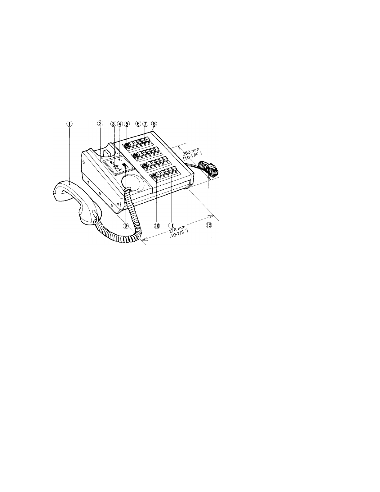
0 AlPHONE
INTERNAL TELEPHONE SYSTEM
832883 0 7 88 ®
MODELS: TB-1 OT (lO-call master)
TB-20T (20-call master)
- INSTRUCTIONS
NAMES AND FUNCTIONS
1. Handset
2. Power lamp
3. Power switch
4. Communication lamp
5. OFF (Cancel) button
6. Selector button
7. Annunciator lamp
8. Terminal block (on back of cabinet)
9. Tone volume control (on panel)
10. Selection lamp
11. Directory card
12. AC plug
FEATURES
1. Tone & lamp anunciation on calling.
2. Telephone sub station with automatic call in.
3. Door station & adaptor available.
4. Warning tone to indicate master has not been cleared.
5. Two msaters per system.
6. Various combinations of conversation:
7. Wall-mountable master station.
8. Call extension speaker available.
9. One paging zone in lieu of one sub station may be installed.
A. Master to master
B. Master to sub
C. Sub to sub through master
D. One master to sub of second master
SPECIFICATIONS
* POWER SOURCE:
* POWER CONSUMPTION:
* CAPACITY:
* WIRING:
* PAGING:
ACllOV, AC 120V, AC 125V, AC220V, AC240V, 50/60Hz.
5.0W maximum
10 & 20 station masters
20 & 40 station additional selectors
2 conductors per sub (Non-polarized), 3 conductors between masters
5 conductors to additional selector (using the included connector)
3 conductors to door station adaptor (2 common and 1 individual)
2 conductors from door station adaptor to door station (Non-polarized)
Use PA-T paging adaptor in conjunction with AlPHONE standard Paging
Amplifier Models: PG-lOB, PG-30B or PG-60B (PG-lOA, PG-30A or PG-60A in
North America) and speakers.
BEFORE YOU INSTALL AND OPERATE THE EQUIPMENT - Prohibitions and precautions-
* Operation;
1. DO NOT HOLD HOOK SWITCH DOWN WHILE PICKING UP HANDSET. THE CALL
TONE SOUNDS THRU THE HANDSET RECEIVER ELEMENT AND COULD CAUSE
HEARING DAMAGE.
* Installation;
1. DO NOT CONNECT ANY TERMINAL ON ANY UNIT TO AC POWER LINES.
2. Be sure to remove plug of power supply from AC outlet before you open the unit or make
wiring connections.
3. Avoid running the connecting wires thru doors, windows or between furniture, which may
pinch and disconnected the wires.
4. The intercom equipment must be installed in as dry and dust-free environment as possible.
* Maintenance;
1. Clean your intercom equipment with a soft cloth dampened with neutral household cleanser.
Never use thinner nor benzine, etc.
2. Do not splash water on the door station by hose, etc.
NEVER
NEVER
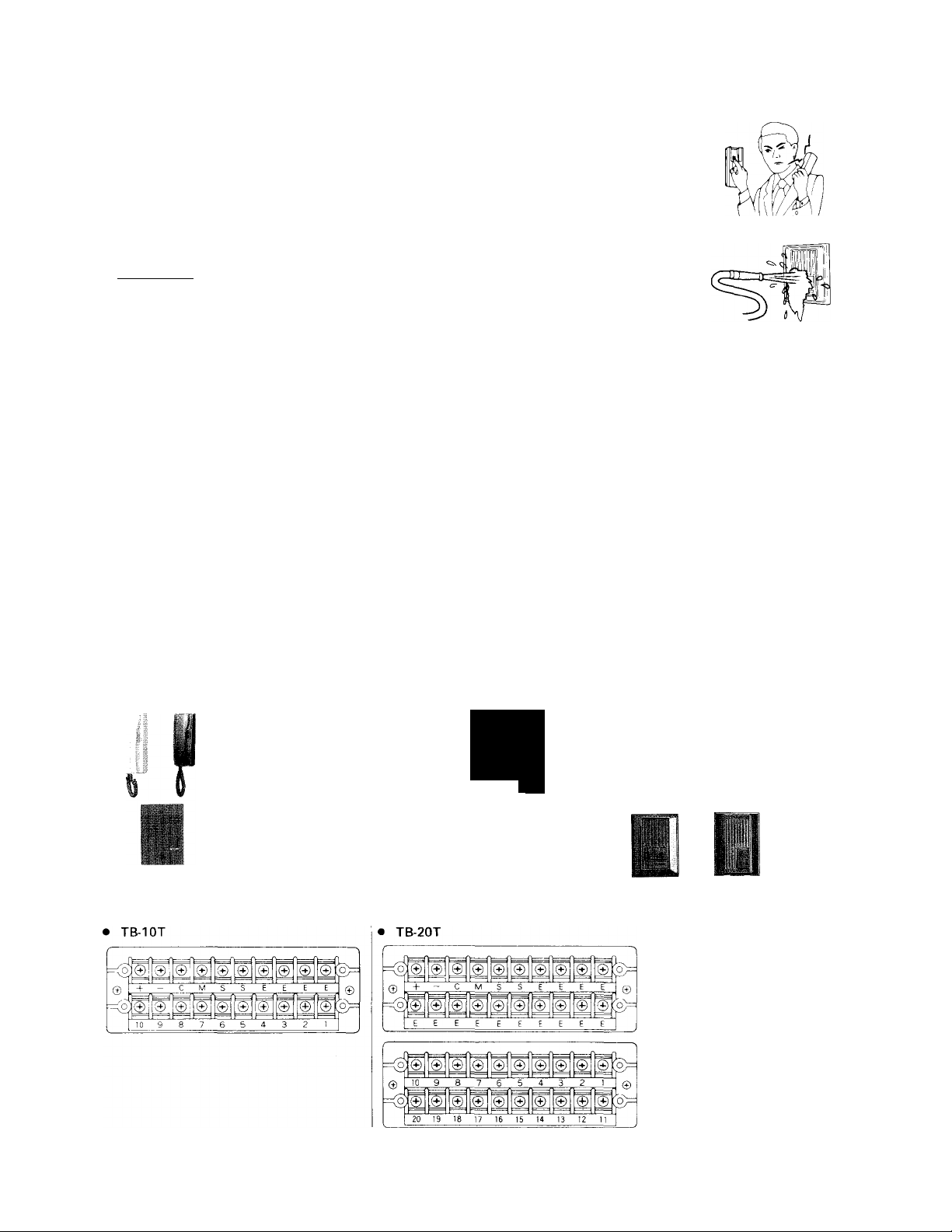
COMPONENTS AVAILABLE FOR USE IN THE TB-T SYSTEM
j
TB-IOT; 10-call master.
PA-T: Paging adaptor.
Connects TB-T master
to a paging system and
background music system.
TB-20T: 20-call master.
TB-20AS: ,4dd-on selector for 20
additional sub stations.
¡0^
TB-TO.AS: .Add-on selector for 40
additional sub stations.
■ Door stations;
All weather resistant type. LED mounted on each cover.
TB-RC: Substation.
TB-RC (R): Sub station with
red case.
ICR-1: Call extension.
ACTUAL TERMINAL LOCATIONS
The master station terminal block is located on back of the cabinet.
Q
IC-DC
lliilli
IC-FY
PG-lOA, PG-30A, PG-60A:
UL «&. CSA LISTED paging amplifier,
low, 30W, 60W (for North America only).
PG-10B,PG-30B, PG-60B:
Standard paging amplifier. lOW, 30W, 60W.
SP-3N.A: Ceiling mount speaker.
Install with or without NBZ-M
square frame.
DB-TS: Door station adaptor
(required for each door station)
ill '■I
IC-NA IC-RA
IC-DA-R
ID-DA
Ij— (JO)] for connecting
IC-KA 1C-JA
ID-NC
sub station
e:
NOTE; For connecting master station and additional selector, joint each connector on
back of the cabinet.
-2-
CJ j for connecting
master station
(M' '
.. for connecting call
extension speaker
.. for power supply to
the door station adaptor
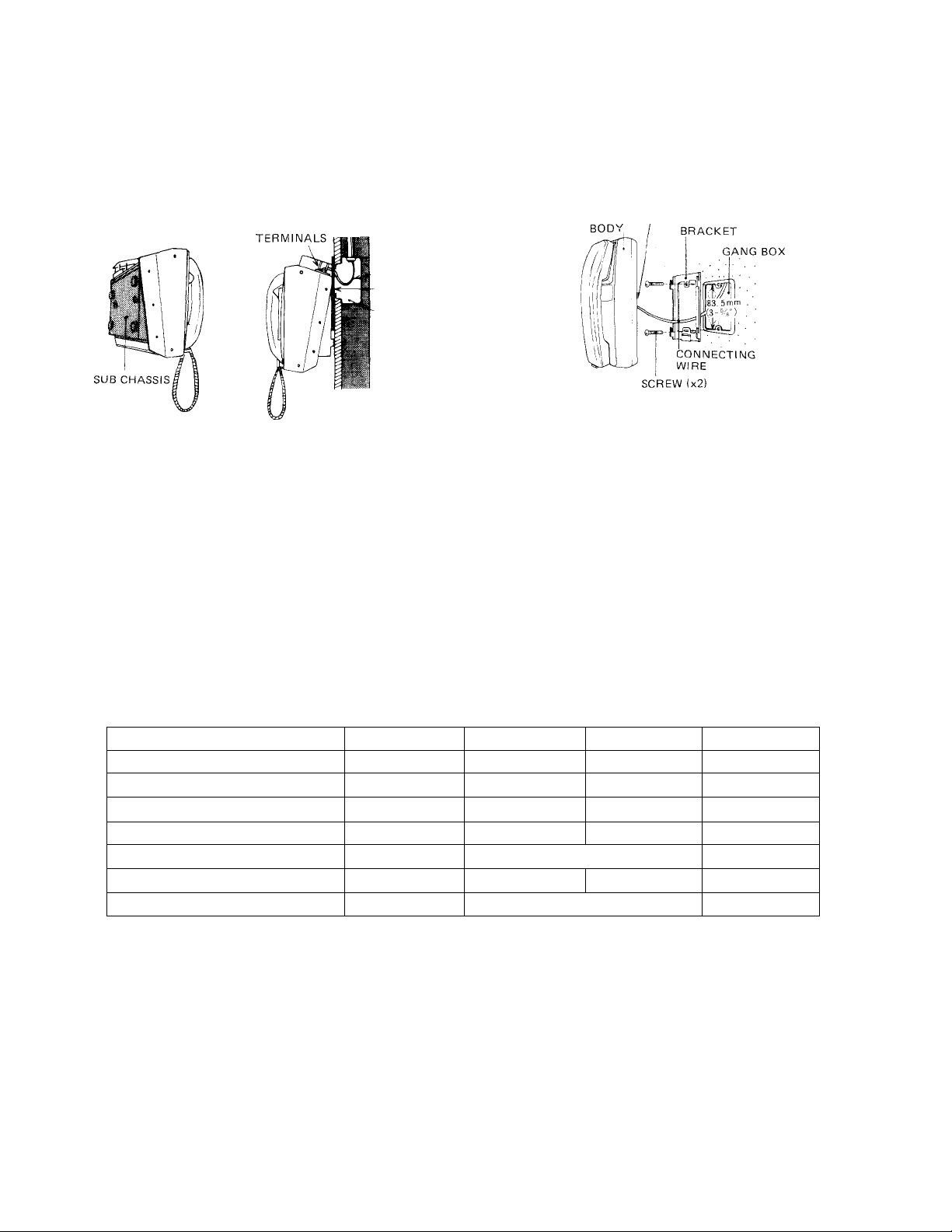
WALL MOUNTING INSTALLATION
MASTER STATION: (1) When wall mounting, install
sub chassis upside down. (2) When mounting to a gang
box, use sub plate (available from Aiphone) as shown in
SUB STATION: Attach the mounting bracket to wall or
gang box.
the figure.
NOTE: Sub chassis must be ALWAYS used for heat
TERMINALS
radiation.
CONNECTING
WIRE
SUB PLATE
GANG BOX
WRING
Layout your system in advance. Determine the location of each station and wiring to each. Two conductors are
required from a master to each sub station under control of that master. Three conudctors are required between the two
masters. Door station adaptor DB-TS should be located as near master as possible. Three conductors are required to DB-TS.
* Connect a single pair of wires (non-polarized) to TB-RC phone, and to numbered station terminals on master
station which you wish to call.
* Adjust call tone volume as desired on the panel of master.
* Do not common one side of pair at any other point than at master. Doing so will affect proper operation of your
system. Refer to the connection diagrams.
* Extend a single pair of wires from terminals: S, S on master to ICR-1, extension call speaker in places where you
wish to receive a call besides at master.
Refer to the chart below and select the proper size wire for your needs.
Master to sub
Master to master
DB-TS to door station
Master to sub
Master to master
DB-TS to door station
24 AWG
750’
400'
300'
0.5 mm
230 m
120 m
90 m
22 AWG 20 AWG
1,300'
650'
500'
0.65 mm 0.8 mm
400 m 600 m
200 m
150 m
After installation of a master and one sub station, we recommend that the system be turned on and
tested for proper operation. The system should further be tested after the addition of each five stations.
INSTALLATION OF DOOR STATION
1. Terminal N indicates the number to which door will announce.
2. DB-TS should be mounted so as to keep wiring to the master as short as possible.
3. Mount door station to wall or gang box as desired.
4. Connect terminals 1 and 2 on DB-TS to door station. Wiring is non-polarized.
5. Connect terminals -i- and — to master station. Observe polarity.
NOTE: DB-TS can not be connected to additional selector.
18 AWG
2,000'
3,000'
1,000' 1,600'
750'
1,200'
1.0 mm
900 m
300 m 480 m
230 m 360 m
Loading...